Hydraulic circulation system for in situ remediation of ... - IAHS
Hydraulic circulation system for in situ remediation of ... - IAHS
Hydraulic circulation system for in situ remediation of ... - IAHS

You also want an ePaper? Increase the reach of your titles
YUMPU automatically turns print PDFs into web optimized ePapers that Google loves.
INTRODUCTION<br />
Hydrvlcgical, ChemkdandBtok^alPmccttes<strong>of</strong> Transfonnatwn and Transport <strong>of</strong> ConUmûu<strong>in</strong>ts <strong>in</strong> Aquatic<br />
Environments (Proceed<strong>in</strong>gs <strong>of</strong> the Rostov-on-Don Symposium, May 1993). <strong>IAHS</strong> Publ. no. 219, 1994. 347<br />
<strong>Hydraulic</strong> <strong>circulation</strong> <strong>system</strong> <strong>for</strong> <strong>in</strong> <strong>situ</strong> <strong>remediation</strong> <strong>of</strong><br />
strippable contam<strong>in</strong>ants and <strong>in</strong> <strong>situ</strong> bioreclamation<br />
(GZB/UVB method)<br />
B. HERRLING & J. STAMM<br />
Institute <strong>of</strong> Hydromechanics, University <strong>of</strong> Karlsruhe, Kaiserstrasse 12,<br />
D-7500 Karlsruhe, Germany<br />
Abstract Vertical <strong>circulation</strong> flows around special screened wells,<br />
which have been used <strong>for</strong> physical (stripp<strong>in</strong>g) or biological <strong>in</strong> <strong>situ</strong><br />
aquifer <strong>remediation</strong>, are discussed. Further, these recirculat<strong>in</strong>g <strong>system</strong>s<br />
can be comb<strong>in</strong>ed with any appropriate on-site <strong>remediation</strong> which<br />
<strong>in</strong>volves extraction and re-<strong>in</strong>filtration <strong>in</strong>to the same well. Design<br />
diagrams are presented and the advantages <strong>of</strong> these flow <strong>system</strong>s are<br />
discussed.<br />
An <strong>in</strong> <strong>situ</strong> <strong>remediation</strong> method us<strong>in</strong>g vertical <strong>circulation</strong> flows around wells with two<br />
screen sections <strong>in</strong> one aquifer, so called "Groundwater Circulation Wells" (German:<br />
Grundwasser-Zirkulations-Brunnen, abbreviation: GZB), has become <strong>in</strong>creas<strong>in</strong>gly<br />
important <strong>for</strong> aquifer <strong>remediation</strong>. Orig<strong>in</strong>ally this idea was used only <strong>for</strong> <strong>in</strong>-<strong>situ</strong><br />
<strong>remediation</strong> <strong>of</strong> aquifers from volatile contam<strong>in</strong>ants <strong>in</strong> so called "Vacuum Vaporizer<br />
Wells" (German: Unterdruck-Verdampfer-Brunnen, abbreviation: UVB) (Herd<strong>in</strong>g et<br />
ah, 1991, 1992). For both the GZB and the UVB, special wells with two screen<br />
sections are employed, one at the aquifer bottom and one at the groundwater surface<br />
or below an aquitard. With<strong>in</strong> the well the groundwater is moved vertically. The<br />
contam<strong>in</strong>ated water enters the well at the bottom and the stripped or treated water<br />
leaves at the top or vice versa. An area <strong>of</strong> vertical flow <strong>circulation</strong> is created near the<br />
well. All the technologies described <strong>in</strong> this paper have been patented by IEG mbH,<br />
D-7410 Reutl<strong>in</strong>gen, Germany.<br />
IN SITU REMEDIATION TECHNIQUES<br />
Physical <strong>remediation</strong> by <strong>in</strong> <strong>situ</strong> stripp<strong>in</strong>g<br />
At numerous sites <strong>in</strong> Germany, and more recently <strong>in</strong> the United States, the UVB<br />
technique have been used <strong>for</strong> <strong>in</strong> <strong>situ</strong> groundwater <strong>remediation</strong> where the subsurface is<br />
contam<strong>in</strong>ated by volatile substances, e.g. volatile chlor<strong>in</strong>ated hydrocarbons, BTEX.<br />
As an alternative to conventional hydraulic redevelopment measures (pump<strong>in</strong>g, <strong>of</strong>f-site<br />
clean<strong>in</strong>g and <strong>in</strong>filtration <strong>of</strong> groundwater), the contam<strong>in</strong>ated groundwater is stripped by<br />
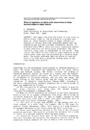
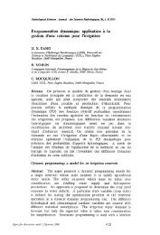
air under slight vacuum <strong>in</strong> the UVB (Fig. 1(a)). Often the well is used <strong>for</strong> vapour
348 B. Herd<strong>in</strong>g & J. Stamm<br />
activated carbon<br />
filter<br />
«•":";•"• filterg'ravel seal<strong>in</strong>g material<br />
(b)<br />
'."••••<br />
I -pipe<br />
,cover with open<strong>in</strong>gs<br />
<strong>for</strong> supply pipes<br />
work<strong>in</strong>g water level<br />
, rest<strong>in</strong>g water level<br />
with device <strong>for</strong><br />
addition <strong>of</strong> nutrients and/or<br />
electron acceptors<br />
-pump generat<strong>in</strong>g the<br />
<strong>circulation</strong> <strong>system</strong><br />
^separation plate<br />
extensive groundwater<br />
<strong>circulation</strong><br />
«4r<br />
borehole fill<strong>in</strong><br />
f i Iter gravel seal<strong>in</strong>g material<br />
aquifer bottom aquifer bottom<br />
Fig. 1 (a) Physical <strong>remediation</strong> by <strong>in</strong> <strong>situ</strong> stripp<strong>in</strong>g us<strong>in</strong>g a vacuum vaporizer well<br />
(UVB), (b) biological <strong>in</strong> <strong>situ</strong> <strong>remediation</strong> us<strong>in</strong>g a groundwater <strong>circulation</strong> well (GZB).<br />
extraction at the same time. The contam<strong>in</strong>ated air is cleaned employ<strong>in</strong>g activated<br />
carbon or <strong>in</strong> the case <strong>of</strong> suitable contam<strong>in</strong>ants by us<strong>in</strong>g bi<strong>of</strong>ilters. Details <strong>of</strong> the UVB<br />
technique have been reported (Herrl<strong>in</strong>g et al., 1991, 1992).<br />
The upper closed part <strong>of</strong> the well is ma<strong>in</strong>ta<strong>in</strong>ed below atmospheric pressure by a<br />
ventilator. This lifts the water level with<strong>in</strong> the well cas<strong>in</strong>g. The fresh air <strong>for</strong> the upper<br />
part <strong>of</strong> the well cas<strong>in</strong>g is <strong>in</strong>troduced through a fresh air pipe: the upper end is open<br />
to the atmosphere, and the lower end term<strong>in</strong>ates <strong>in</strong> a p<strong>in</strong>hole plate. The height <strong>of</strong> the<br />
p<strong>in</strong>hole plate is adjusted such that the water pressure is lower there than the<br />
atmospheric pressure. There<strong>for</strong>e, the fresh air is drawn <strong>in</strong>to the <strong>system</strong>. The reach<br />
between the p<strong>in</strong>hole plate and the water surface <strong>in</strong> the well cas<strong>in</strong>g is the stripp<strong>in</strong>g<br />
zone, <strong>in</strong> which an air bubble flow develops. The ris<strong>in</strong>g air bubbles produce a pump<br />
effect, which moves the water up and causes a suction effect at the well bottom. In<br />
recent wells, a separat<strong>in</strong>g plate and an additional pump (Fig. 1(a)) are used to<br />
re<strong>in</strong><strong>for</strong>ce the pump<strong>in</strong>g effect <strong>of</strong> the air bubbles. Additionally, soil gas is drawn from<br />
the surround<strong>in</strong>g contam<strong>in</strong>ated unsaturated zone at many sites. Stripped air and possibly<br />
soil gas are transported through the ventilator and across activated carbon, onto which<br />
the contam<strong>in</strong>ants are adsorbed. Thus, only clean air escapes <strong>in</strong>to the atmosphere. One<br />
well should be used to remediate only one aquifer (phreatic or conf<strong>in</strong>ed) and should<br />
not connect different aquifers.<br />
The clean<strong>in</strong>g effect <strong>of</strong> the well is based on reduced pressure, which re<strong>in</strong><strong>for</strong>ces the<br />
volatilization <strong>of</strong> contam<strong>in</strong>ants from the water and, as a result <strong>of</strong> the air <strong>in</strong>termix<strong>in</strong>g,<br />
their transfer to the considerable surface area <strong>of</strong> the air bubbles. The permanent<br />
vibration caused by the air bubbles also helps the volatilization process. This vibration<br />
is transmitted as compression and shear waves <strong>in</strong>to sediment and fluid and presumably
<strong>Hydraulic</strong> <strong>circulation</strong> <strong>system</strong> <strong>for</strong> <strong>remediation</strong> and bioreclamation 349<br />
<strong>in</strong>fluences the mobility <strong>of</strong> the contam<strong>in</strong>ants, even outside the well. The<br />
upward-stream<strong>in</strong>g, stripped groundwater leaves the well cas<strong>in</strong>g through the upper<br />
screen section near the water table, which is lifted <strong>in</strong> a phreatic aquifer by the<br />
pump<strong>in</strong>g process expla<strong>in</strong>ed above and the reduced pressure. It then returns through the<br />
aquifer <strong>in</strong> an extensive <strong>circulation</strong> to the well bottom. In this way, the groundwater<br />
surround<strong>in</strong>g the well is also remediated. The artificial groundwater <strong>circulation</strong><br />
determ<strong>in</strong>es the sphere <strong>of</strong> <strong>in</strong>fluence <strong>of</strong> a well and is overlapped with the natural<br />
groundwater flow (as described below).<br />
In the case <strong>of</strong> DNAPL contam<strong>in</strong>ation, the UVB is operated upwardly as <strong>in</strong><br />
Fig. 1(a). In the case <strong>of</strong> LNAPL, the contam<strong>in</strong>ated water enters the well through the<br />
upper screen, is treated there by <strong>in</strong> <strong>situ</strong> stripp<strong>in</strong>g, and leaves the well through the<br />
lower screen.<br />
In <strong>situ</strong> bio<strong>remediation</strong><br />
When the groundwater is contam<strong>in</strong>ated by non-volatile substances, but which are<br />
suitable <strong>for</strong> bio<strong>remediation</strong>, the extensive <strong>circulation</strong> flow around the GZB (see<br />
Fig. 1(b)) can be used to distribute nutrients and/or electron acceptors throughout the<br />
unsaturated zone. Any water-soluble substance can be added <strong>in</strong> measured quantities<br />
while the groundwater passes the well cas<strong>in</strong>g. In this case the aquifer itself is used as<br />
a bioreactor. Alternately, a special bioreactor or other technologies have been <strong>in</strong>stalled<br />
with<strong>in</strong> the well cas<strong>in</strong>g between the lower and upper screen <strong>in</strong> case <strong>of</strong> special
350 B. Herrl<strong>in</strong>g & J. Stamm<br />
contam<strong>in</strong>ants (Fig. 2(a)). Of course, the latter <strong>in</strong> <strong>situ</strong> techniques can be directly<br />
comb<strong>in</strong>ed with the <strong>in</strong> <strong>situ</strong> stripp<strong>in</strong>g <strong>for</strong> mixed contam<strong>in</strong>ants, or <strong>for</strong> elim<strong>in</strong>at<strong>in</strong>g the<br />
biogas (e.g. C02, N2) from the groundwater <strong>in</strong> the <strong>circulation</strong>. Elim<strong>in</strong>at<strong>in</strong>g C02 also<br />
prevents undesirable Ph drops. In <strong>situ</strong> stripp<strong>in</strong>g is most suitable <strong>for</strong> the complete<br />
mix<strong>in</strong>g <strong>of</strong> added nutrients with the groundwater.<br />
When oxygen is needed <strong>for</strong> bio<strong>remediation</strong>, e.g. <strong>for</strong> hydrocarbons, 02 saturation<br />
is atta<strong>in</strong>ed <strong>in</strong>expensively by <strong>in</strong> <strong>situ</strong> stripp<strong>in</strong>g with air (Fig. 1(a)). When the discharge<br />
through the well cas<strong>in</strong>g is <strong>in</strong>creased, the quantity <strong>of</strong> captured groundwater flow<strong>in</strong>g<br />
from upstream grows more slowly (Fig. 6(d)). It rema<strong>in</strong>s constant when several wells<br />
are <strong>in</strong> one l<strong>in</strong>e, normal to the natural groundwater flow. Thus, by <strong>in</strong>tensify<strong>in</strong>g the<br />
<strong>circulation</strong> flow around the UVB relative to the captured contam<strong>in</strong>ated groundwater,<br />
the quantity <strong>of</strong> 02 transferred to the contam<strong>in</strong>ated water can be considerably <strong>in</strong>creased.<br />
ON-SITE REMEDIATION USING A GZB<br />
When any on-site <strong>remediation</strong> technique is appropriate, e.g. <strong>for</strong> the elim<strong>in</strong>ation <strong>of</strong><br />
dissolved heavy metals from the groundwater, the vertical <strong>circulation</strong> flow <strong>of</strong> a GZB<br />
can be utilized to advantage. The groundwater enter<strong>in</strong>g the well is pumped above<br />
ground, treated, and <strong>in</strong>filtrated <strong>in</strong> the same well us<strong>in</strong>g the other well screen<br />
(Fig. 2(b)).<br />
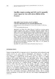
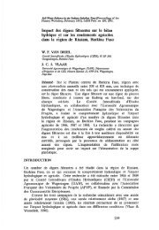
Furthermore, follow<strong>in</strong>g these ideas, the GZB can be also used as a pump or<br />
<strong>in</strong>filtration well <strong>for</strong> standard on-site <strong>remediation</strong>s. In this case a partial discharge<br />
withdrawal or <strong>in</strong>filtration is taken from or added to the total discharge through the well<br />
cas<strong>in</strong>g (Fig. 3). There is a special ratio between the total well discharge and the<br />
extracted or <strong>in</strong>filtrated quantity <strong>of</strong> water that allows to extract or to <strong>in</strong>filtrate water<br />
without any change <strong>of</strong> head at the top <strong>of</strong> the well. This ratio has been derived<br />
numerically <strong>for</strong> conf<strong>in</strong>ed aquifer conditions. Of course, at some distance from the<br />
well, a smooth deviation from the rest<strong>in</strong>g groundwater head will be found. However,<br />
<strong>in</strong> the case <strong>of</strong> low well capacity, cont<strong>in</strong>uous pump<strong>in</strong>g can be realized at a higher rate.<br />
Infiltration can be carried out <strong>for</strong> a much greater quantity even <strong>for</strong> a small distance<br />
between the surface and the groundwater table. Furthermore, dur<strong>in</strong>g the pump<br />
operation, the turbulent mix<strong>in</strong>g <strong>of</strong> air and water <strong>in</strong> the filter gravel <strong>of</strong> the well, which<br />
<strong>of</strong>ten causes unwanted precipitation, can be avoided.<br />
NUMERICAL-MODELLING INVESTIGATIONS<br />
Flow <strong>system</strong>s <strong>of</strong> a GZB or UVB without extraction or <strong>in</strong>filtration<br />
The vertical <strong>circulation</strong> flow around the GZB and UVB has been a matter <strong>of</strong><br />
cont<strong>in</strong>u<strong>in</strong>g numerical-modell<strong>in</strong>g <strong>in</strong>vestigations (Herrl<strong>in</strong>g & Stamm, 1992). Up to now<br />
this has been achieved only <strong>for</strong> conf<strong>in</strong>ed aquifer conditions, which permits the<br />
superposition <strong>of</strong> the flow fields <strong>of</strong> different wells and the natural groundwater flow;<br />
the local reduced pressure field (<strong>in</strong> case <strong>of</strong> a UVB) is neglected.<br />
Further, density effects are ignored; only steady-state conditions are taken <strong>in</strong>to<br />
account and, <strong>for</strong> estimat<strong>in</strong>g the capture zone, only convective transport is considered.
<strong>Hydraulic</strong> <strong>circulation</strong> <strong>system</strong> <strong>for</strong> <strong>remediation</strong> and bioreclamation 351<br />
cv-ii<br />
-QF<br />
i valve<br />
rest<strong>in</strong>g water level<br />
7<br />
work<strong>in</strong>g water level<br />
separation plate<br />
pump<br />
groundwater <strong>circulation</strong><br />
borehole fill<strong>in</strong>g :<br />
0>)<br />
"vs'ww: 7/xws/<br />
Q = 0I + Qc<br />
work<strong>in</strong>g water level<br />
rest<strong>in</strong>g water level<br />
separation plate<br />
groundwater <strong>circulation</strong><br />
/ borehole fill<strong>in</strong>g:<br />
.* 'f Q "••.••.• filter gravel seal<strong>in</strong>g material &•; filter gravel seal<strong>in</strong>g material<br />
:.-i<br />
^aquifer bottom \iquifer bottom<br />
Fig. 3 Groundwater <strong>circulation</strong> wells (GZB) <strong>for</strong> (a) extraction and (b) <strong>in</strong>filtration <strong>of</strong><br />
water.<br />
The general character <strong>of</strong> the vertical <strong>circulation</strong> flow is demonstrated <strong>in</strong> Fig. 4. In a<br />
vertical longitud<strong>in</strong>al section parallel to the natural groundwater flow, streaml<strong>in</strong>es mark<br />
the flow around two upward pump<strong>in</strong>g GZB, their separation be<strong>in</strong>g made equal to the<br />
distance between stagnation po<strong>in</strong>t and well axis. The strong vertical <strong>circulation</strong> flow<br />
especially between the wells, which is extremely beneficial <strong>in</strong> a highly polluted area<br />
near the contam<strong>in</strong>ation source, is evident.<br />
Figure 5 presents a view <strong>of</strong> the numerically calculated separat<strong>in</strong>g stream surfaces<br />
<strong>of</strong> n<strong>in</strong>e water bodies <strong>in</strong> relation with the flow around three GZBs. They are positioned<br />
at a maximum distance normal to the natural groundwater flow so that no water can<br />
pass between the wells without hav<strong>in</strong>g been treated. With the contam<strong>in</strong>ated<br />
groundwater flow<strong>in</strong>g from the left the follow<strong>in</strong>g salient features can be clearly seen:<br />
the separat<strong>in</strong>g stream surfaces <strong>of</strong> the contam<strong>in</strong>ated water captured by the three GZB<br />
(left), the surfaces <strong>of</strong> the water bodies hav<strong>in</strong>g been treated and circulat<strong>in</strong>g around the<br />
wells (centre), and <strong>of</strong> the treated water flow<strong>in</strong>g downstream (right).<br />
GZB GZB<br />
Fig. 4 Streaml<strong>in</strong>es around two GZBs demonstrated <strong>in</strong> a vertical longitud<strong>in</strong>al section<br />
parallel to the natural groundwater flow.
352 B. Herrl<strong>in</strong>g & J. Stamm<br />
(a) (b)<br />
Fig. 5 Separat<strong>in</strong>g stream surfaces <strong>of</strong> the different water bodies <strong>in</strong> the outside flow <strong>of</strong><br />
a GZB: captured, circulat<strong>in</strong>g, and flow<strong>in</strong>g downstream water <strong>in</strong> (a) a real <strong>situ</strong>ation,<br />
and (b) water bodies separated <strong>for</strong> clarification.<br />
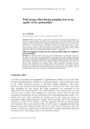
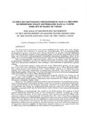
At most <strong>remediation</strong> sites, a natural groundwater flow exists. Figure 6 shows<br />
numerical results represented <strong>in</strong> dimensionless <strong>for</strong>m <strong>for</strong> the design <strong>of</strong> GZB or UVB<br />
<strong>in</strong>stallations under these conditions. In Fig. 6(a), the horizontal distance (S) <strong>of</strong> the<br />
stagnation po<strong>in</strong>t from the well axis is described. The ratio SI H is dependent on the<br />
parameters QI(H 2 v), KH/KV, and a/H. Q denotes the vertical discharge through one<br />
well, H the aquifer thickness, v the natural Darcy velocity at the site, a the length <strong>of</strong><br />
the upper or lower screen section, and KH and Kv the horizontal and vertical hydraulic<br />
conductivities. The location <strong>of</strong> the stagnation po<strong>in</strong>t is highly sensitive to the anisotropy<br />
<strong>of</strong> the aquifer.<br />
The results <strong>of</strong> Fig. 6(b)-(d) have been calculated <strong>for</strong> an upstream distance <strong>of</strong> 5H<br />
from the well and <strong>for</strong> a constant ratio <strong>of</strong> a/H = 0.25. The results are discussed <strong>for</strong><br />
wells that pump upward. The widths BT and BB <strong>of</strong> the upstream zone, measured at the<br />
aquifer top and bottom, are shown <strong>in</strong> Fig. 6(b). The ratios Bj/H and BB/H are aga<strong>in</strong><br />
dependent on the ratios Q/(H 2 v), KH/KV, and a/H. For small values <strong>of</strong> Q/(H 2 v), the<br />
upper part <strong>of</strong> the capture zone does not reach the top <strong>of</strong> the aquifer. This implies that<br />
<strong>for</strong> remediat<strong>in</strong>g a plume, a m<strong>in</strong>imum well discharge (0 is required. Aga<strong>in</strong>, the results<br />
are quite sensitive to the degree <strong>of</strong> the anisotropy.<br />
When remediat<strong>in</strong>g a wide contam<strong>in</strong>ation plume, several wells are used <strong>in</strong> a l<strong>in</strong>e<br />
normal to the direction <strong>of</strong> the natural groundwater flow. The length (D) denotes the<br />
maximum well distance at which the contam<strong>in</strong>ated groundwater cannot pass between<br />
the wells without be<strong>in</strong>g cleaned or treated. The ratio D/H is dependent on the same<br />
parameters as be<strong>for</strong>e (Fig. 6(c)). When a plume <strong>of</strong> width Wis to be cleaned, the<br />
number («) <strong>of</strong> well <strong>in</strong>stallations can be estimated by:<br />
n = (W - BT)ID + 1<br />
When a plume is remediated, the contam<strong>in</strong>ated water <strong>of</strong> quantity Q0, flow<strong>in</strong>g <strong>in</strong>to the<br />
capture zone <strong>of</strong> a s<strong>in</strong>gle well from upstream, is diluted with water that has already<br />
flowed through the well and circulates around it. Thus, the contam<strong>in</strong>ant concentration
(c)<br />
<strong>Hydraulic</strong> <strong>circulation</strong> <strong>system</strong> <strong>for</strong> <strong>remediation</strong> and bioreclamation 353<br />
(a)<br />
5 10 15 20 25 30 35 40 45 50 -S- 5 10 15 20 25 30 35 40 45 50 Q<br />
5 10 15 20 25 30 35 40 45 50 Q<br />
(b)<br />
(d)<br />
Qo -<br />
-<br />
07 •<br />
0.6 -<br />
OS -<br />
0.4 -<br />
0.3 -<br />
02-<br />
0.1<br />
-I<br />
-I \\<br />
- \ \ \<br />
\ ^ "<br />
SL: = 0.25<br />
H<br />
KH<br />
Kv<br />
:^r—10<br />
—— 5<br />
— • — 1<br />
0 - 1 I I 1 1<br />
0 5 10 15 20 25 30 35 40 45 50 Q<br />
Fig. 6 (a) Distances (S) <strong>of</strong> the stagnation po<strong>in</strong>t from the well axis, (b) widths (BT) and<br />
(Bg) <strong>of</strong> the upstream capture zone at the aquifer top and bottom, (c) maximum well<br />
distance (D) at which the contam<strong>in</strong>ated groundwater cannot pass between the wells<br />
without be<strong>in</strong>g treated, (d) upstream discharge (Q0) <strong>in</strong> the capture zone, which is<br />
diluted with the circulat<strong>in</strong>g water to the total well discharge (0.<br />
<strong>of</strong> the water with<strong>in</strong> the well cas<strong>in</strong>g will be lower than <strong>in</strong> the upstream plume; near a<br />
contam<strong>in</strong>ation source, the <strong>situ</strong>ation is reversed.<br />
Figure 6(d) illustrates the portion Q0 <strong>of</strong> the total well discharge Q. The ratio Q0/Q<br />
is aga<strong>in</strong> dependent on the same parameters as the widths <strong>of</strong> the upstream capture zone.<br />
The sphere <strong>of</strong> <strong>in</strong>fluence <strong>of</strong> the <strong>circulation</strong> around a GZB, at sites with natural<br />
groundwater flow, is <strong>of</strong> special <strong>in</strong>terest. In the direction <strong>of</strong> natural groundwater flow,<br />
this sphere has a maximum expansion <strong>of</strong> S (see Fig. 6(a)) to the upstream and<br />
downstream sides. Normal to this direction, the maximum radius <strong>of</strong> the sphere <strong>of</strong><br />
<strong>circulation</strong> is approximated by (BB + 5r)/4 (Fig. 6(b))and <strong>in</strong> the case <strong>of</strong> several wells
354 B. Herrl<strong>in</strong>g & J. Stamm<br />
<strong>in</strong> one l<strong>in</strong>e by D/2 (Fig. 6(c)). Figure 6 can be used <strong>for</strong> the design <strong>of</strong> one GZB or a<br />
GZB field when the parameters KjjIKy and QI{H 2 v) can be estimated, and where Q<br />
depends on the well size and on the additional pump. For an irregular well field, a<br />
layered aquifer, or special critical cases, additional numerical calculations can be<br />
per<strong>for</strong>med.<br />
Flow <strong>system</strong> <strong>of</strong> a GZB with groundwater extraction or <strong>in</strong>filtration<br />
Presently, numerical results are only available <strong>for</strong> the case <strong>of</strong> absence <strong>of</strong> natural<br />
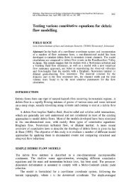
groundwater flow and <strong>for</strong> conf<strong>in</strong>ed aquifer conditions. When a GZB (Fig. 3(a))is used<br />
to split the vertical well discharge (Q), pumped from the lower screen section, <strong>in</strong>to an<br />
extracted quantity (QE) and an amount (Qc), <strong>in</strong>filtrated <strong>in</strong> the upper screen section and<br />
generat<strong>in</strong>g the <strong>circulation</strong> flow around the well, it is possible to avoid any change <strong>of</strong><br />
heads at the well top <strong>for</strong> a special ratio <strong>of</strong> QE/QC. This ratio is only dependent on<br />
KfjIKy and a/H. Figure 7(a) demonstrates <strong>for</strong> a/h — 0.25, QE can be about two to<br />
three times <strong>of</strong> Qc depend<strong>in</strong>g on the aquifer anisotropy.<br />
For this special ratio <strong>of</strong> QEIQC, the decrease <strong>of</strong> the head at the well bottom (no<br />
change <strong>of</strong> the heads at the well top) is —Ah (Fig. 7(b)). In a dimensionless<br />
description, Ah/H is dependent on the parameters QE/(H 2 KH), K^KV, and a/H<br />
(Fig. 7(b): a/H = 0.25). An important check <strong>of</strong> cavitation below the packer can be<br />
carried out us<strong>in</strong>g this diagram.<br />
In the case <strong>of</strong> <strong>in</strong>filtration <strong>of</strong> a quantity (£>7) <strong>in</strong> a GZB (Fig. 3(b)), the ratio Q}IQC<br />
can be taken from the diagram <strong>of</strong> Fig. 7(a) as well, when no change <strong>of</strong> heads is<br />
demanded at the well top. In this case, Q leaves the GZB through the lower screen and<br />
Qc enters the well through the upper screen. The <strong>in</strong>crease <strong>of</strong> head Ah at the well<br />
bottom can be estimated from Fig. 7(b).<br />
At some distance (r) from the well axis, a maximum head deviation (j) from the<br />
rest<strong>in</strong>g water level will result at the aquifer top. The dimensionless parameter r/H is<br />
dependent on K^KV and a/H, and f/H (negative <strong>for</strong> groundwater extraction and<br />
positive <strong>for</strong> <strong>in</strong>filtration) depends on QE/(H 2 KH), Kjj/Ky and a/H. Figures 7(c) and 7(d)<br />
present results <strong>for</strong> a/H = 0.25.<br />
ADVANTAGES OF A GZB AND UVB<br />
The technologies presented, <strong>in</strong> particular the vertical <strong>circulation</strong> flow, <strong>of</strong>fer many<br />
advantages, especially when compared with a standard pump and treat <strong>system</strong>. In<br />
addition to the advantages expla<strong>in</strong>ed above, these are:<br />
(a) For wells operat<strong>in</strong>g upward, no lower<strong>in</strong>g <strong>of</strong> the heads appears;<br />
(b) even at low well capacity, <strong>remediation</strong> operation is cont<strong>in</strong>uous;<br />
(c) less permeable, horizontal layers are penetrated vertically;<br />
(d) the <strong>remediation</strong> <strong>of</strong> the groundwater takes place down to the aquifer bottom;<br />
(e) the groundwater flow regime is <strong>in</strong>fluenced only locally <strong>in</strong> case <strong>of</strong> no partial<br />
discharge withdrawal or <strong>in</strong>filtration;<br />
(f) <strong>in</strong> a closed air <strong>circulation</strong> <strong>of</strong> a UVB unwanted pH <strong>in</strong>creases and the <strong>in</strong>volved<br />
precipitation process can be avoided;
a<br />
a<br />
o<br />
a<br />
a<br />
(a)<br />
3.5<br />
(c)<br />
Li<br />
0.6<br />
0.4<br />
<strong>Hydraulic</strong> <strong>circulation</strong> <strong>system</strong> <strong>for</strong> <strong>remediation</strong> and bioreclamation 355<br />
a / H = 0.25<br />
4 6<br />
a / H = 0.25<br />
Ki i / Kv<br />
4 6<br />
Kl, / Kv<br />
y<br />
(b)<br />
0.1 0.2 0.3<br />
Q,:/(H 2 K„) , Q,/(H 2 KH)<br />
0.1 0.2 0.3<br />
Q,;/(H 2 K„) , Q./fHX)<br />
Fig. 7 (a) Ratio QEIQC and 2/ôc f° r no h^d change at the well top, (b) head<br />
changes Ah at the well bottom, (c) distance r from the well axis with maximum head<br />
deviation/, and (d) maximum head deviation/.<br />
(g) the presented <strong>in</strong> <strong>situ</strong> technology avoids waste-water discharge and groundwater<br />
extraction.<br />
Acknowledgements The authors gratefully acknowledge IEG mbH, D-7410 Reutl<strong>in</strong>gen<br />
(Germany), <strong>for</strong> f<strong>in</strong>ancially support<strong>in</strong>g these <strong>in</strong>vestigations. Further, B. Bernhardt, IEG<br />
mbH, <strong>in</strong>ventor and patent holder <strong>of</strong> the GZB and UVB method, and E. J. Alesi, IEG
356<br />
B. Herrl<strong>in</strong>g & J. Stamm<br />
Technologies Corp., Charlotte, North Carol<strong>in</strong>a 28217 (USA), are thanked <strong>for</strong> many<br />
helpful discussions.<br />
REFERENCES<br />
Herrl<strong>in</strong>g, B., Stamm, J. & Buermann, W. (1991) <strong>Hydraulic</strong> <strong>circulation</strong> <strong>system</strong> <strong>for</strong> <strong>in</strong> <strong>situ</strong> bioreclamation and/or <strong>in</strong><br />
<strong>situ</strong> <strong>remediation</strong> <strong>of</strong> strippable contam<strong>in</strong>ation. In: In <strong>situ</strong> Bioreclamation, Applications and Investigations <strong>for</strong><br />
Hydrocarbon and Contam<strong>in</strong>ated Site Remediation (ed. by E. H<strong>in</strong>chee & R. F. Olfenbuttel), 173-195.<br />
Butterworth-He<strong>in</strong>emann, Boston.<br />
Herrl<strong>in</strong>g, B. & Stamm, J. (1992) Numerical results <strong>of</strong> calculated 3D vertical <strong>circulation</strong> flows around wells with<br />
two screen sectiorts <strong>for</strong> <strong>in</strong> <strong>situ</strong> aquifer <strong>remediation</strong>. In: Computational Methods <strong>in</strong> Water Resources, IX, vol.<br />
1: Numerical Methods <strong>in</strong> Water Resources (ed. by T. F. Russell et al), 483-492. Elsevier Applied Science,<br />
London.<br />
Herrl<strong>in</strong>g, B., Stamm, J., Alesi, E. J. &Br<strong>in</strong>nel, P. (1992) Vacuum vaporizer wells (UVB) <strong>for</strong> <strong>in</strong> <strong>situ</strong> <strong>remediation</strong><br />
<strong>of</strong> volatile and strippable contam<strong>in</strong>ants <strong>in</strong> the unsaturated and saturated zone. In: Proc. Symp. on Soil Vent<strong>in</strong>g<br />
(April-May 1991, Houston, Texas), 203-228. US EPA/600/R-92/174.