Induction hardening of complex geometry and geared parts - eldec
Induction hardening of complex geometry and geared parts - eldec
Induction hardening of complex geometry and geared parts - eldec

You also want an ePaper? Increase the reach of your titles
YUMPU automatically turns print PDFs into web optimized ePapers that Google loves.
International Magazine for Industrial Furnaces<br />
Heat Treatment & Equipment<br />
www.heatprocessing-online.com<br />
10 th - 12 th October 2012<br />
Wiesbaden, Germany<br />
03 I 2012<br />
ISSN 1611-616X<br />
Vulkan-Verlag<br />
Read all about the<br />
HEAT TREATMENT CONGRESS 2012<br />
Visit us in Hall 9 / Booth 905<br />
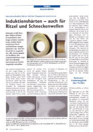
<strong>Induction</strong> <strong>hardening</strong> <strong>of</strong> <strong>complex</strong><br />
<strong>geometry</strong> <strong>and</strong> <strong>geared</strong> <strong>parts</strong><br />
by Fabio Biasutti, Christian Krause, Sergio Lupi<br />
High-efficiency quenching <strong>and</strong><br />
tempering plants based on<br />
comprehensive process expertise<br />
LOI Thermprocess GmbH - Tenova Iron & Steel Division<br />
Am Lichtbogen 29 - 45141 Essen / Germany<br />
Phone +49 (0)201 1891.1 - Fax +49 (0)201 1891.321<br />
info@loi-italimpianti.de - www.loi-italimpianti.com<br />
HK 2012<br />
Visit us: Härtereikolloquium 2012<br />
Oct 10-12, Wiesbaden, Germany<br />
NEW: Hall 9, Booth 911<br />
Tenova S.p.A., LOI Italimpianti<br />
Via Albareto 31 - 16153 Genoa Sestri Ponente / Italy<br />
Phone +39 010 6054807 - Fax +39 010 6054741<br />
info@loi-italimpianti.it - www.tenovagroup.com<br />
Published in heat processing 3/2012 - Vulkan Verlag GmbH Essen (Germany)<br />
Visit us: Ankiros 2012<br />
Sep 13-16, Istanbul, Turkey<br />
Booth H6-C130
REPORTS <strong>Induction</strong> Technology<br />
<strong>Induction</strong> <strong>hardening</strong> <strong>of</strong> <strong>complex</strong><br />
<strong>geometry</strong> <strong>and</strong> <strong>geared</strong> <strong>parts</strong><br />
by Fabio Biasutti, Christian Krause, Sergio Lupi<br />
Mechanical gear <strong>parts</strong> for automotive or aeronautical industry are highly stressed toothed workpieces, which need to be<br />
heat treated in order to improve their mechanical properties. Up to now the most common heat treatment technology<br />
is carburizing. This method permits to achieve strength <strong>and</strong> wear resistance but cannot be integrated in a production<br />
line. Moreover, the carburizing process takes several hours <strong>and</strong> the workpiece must be completed heated up to the<br />
austenization temperature, resulting in extensive deformation. The induction contour <strong>hardening</strong> process is an alternative<br />
to carburizing. The purpose <strong>of</strong> this paper is to present the induction contour <strong>hardening</strong> process with particular reference<br />
to <strong>geared</strong> <strong>parts</strong>. In the paper are first recalled the basic laws <strong>of</strong> induction heating <strong>and</strong> is given an historical overview <strong>of</strong><br />
the induction <strong>hardening</strong> process <strong>of</strong> gears. <strong>Induction</strong> <strong>hardening</strong> involves electromagnetic <strong>and</strong> metallurgical phenomena,<br />
which are described in the third <strong>and</strong> fourth paragraph. Some practical industrial applications <strong>of</strong> the induction <strong>hardening</strong><br />
are presented in the fifth paragraph.<br />
BASICS OF INDUCTION HEATING<br />
The induction <strong>hardening</strong> process consists <strong>of</strong> two steps:<br />
�rst the heating above the austenization temperature <strong>of</strong><br />
the surface layer that has to be hardened, <strong>and</strong> second the<br />
quenching below a de�ned temperature (martensite �nish<br />
or room temperature).<br />
The heating is performed by electromagnetic induction, in<br />
which are involved di�erent physical phenomena <strong>and</strong> laws, i.e.:<br />
Electromagnetic<br />
<strong>Induction</strong><br />
Electromagnetic<br />
�eld distribution<br />
Conversion <strong>of</strong> electromagnetic<br />
energy into heat<br />
Temperature �eld<br />
distribution<br />
Faraday, Neumann,<br />
Lenz laws<br />
Maxwell laws<br />
Joule law<br />
Fourier equation<br />
With reference to the system <strong>of</strong> Fig. 1, in which an alternative<br />
current I �ows in the exciting coil <strong>and</strong> produces<br />
a magnetic �ux Ф variable in time, according to the law<br />
<strong>of</strong> the electromagnetic induction an e.m.f. is induced in<br />
every closed path inside the work piece. This e.m.f. causes<br />
induced currents Ik (eddy or Foucault currents) to �ow<br />
within the mass <strong>of</strong> the body which, in turn, generates<br />
power according to the Joule’s law, thus heating the body.<br />
Like the coil current, the induced currents Ik also produce<br />
an alternating magnetic �eld which, in accordance<br />
with Lenz’s principle, is in opposition to the exciting �eld.<br />
The two �elds are superimposed, <strong>and</strong> the result is a radial<br />
reduction <strong>of</strong> the magnetic �eld towards the inside <strong>of</strong> the<br />
work piece <strong>and</strong> the outside <strong>of</strong> the inductor. This is known<br />
as “skin e�ect”, because the resulting induced current <strong>and</strong><br />
power density distributions (the heating sources) are not<br />
uniform inside the work piece <strong>and</strong> concentrate in a surface<br />
(or “skin”) layer.<br />
This surface layer has radial dimensions comparable with<br />
the so called “penetration depth”, given by:<br />
2 ρ<br />
mm][<br />
2π<br />
f µ<br />
60 heat processing 3-2012<br />
δ =<br />
0<br />
with: ρ - resistivity [Ωm]; μ0 = 4 π ·10 -7 - magnetic permeability<br />
<strong>of</strong> vacuum [H/m]; m - relative magnetic permeability;<br />
f – frequency <strong>of</strong> the inductor <strong>and</strong> workpiece currents [Hz].<br />
The heating sources cause the heating <strong>of</strong> the workpiece,<br />
<strong>and</strong> the temperature increase follows the law <strong>of</strong> thermal<br />
conduction (Fourier equation).<br />
HISTORICAL OVERVIEW<br />
Since the beginning <strong>of</strong> the development <strong>of</strong> induction heating,<br />
the induction <strong>hardening</strong> <strong>of</strong> gears has been at the attention<br />
<strong>of</strong> researchers <strong>and</strong> engineers because <strong>of</strong> the advantages <strong>of</strong><br />
(1)
3-2012 heat processing<br />
Fig. 1:<br />
Sketch <strong>of</strong> the inductor coilwork<br />
piece system: a current<br />
I [A] � owing in the coil produces<br />
a magnetic � ux Ф [Wb]<br />
which induces eddy currents<br />
Ik [A] in the work piece.<br />
Fig. 2:<br />
Classi� cation <strong>of</strong> the di� erent<br />
spin <strong>hardening</strong> methods [14]<br />
this technique, such as short heating times, strict process<br />
control, low distortion <strong>of</strong> the heat treated <strong>parts</strong>. An historical<br />
document is, in this sense, the patent US1687656 <strong>of</strong> Brown<br />
[1] as much as the work <strong>of</strong> Hogel [2] in 1938 <strong>and</strong> the work <strong>of</strong><br />
Vologdin [3] 1939. In the 1940s many researches <strong>and</strong> publications<br />
related to the improvement <strong>of</strong> the gear <strong>hardening</strong> were<br />
developed in several countries around the world [15]. It was<br />
found relatively early that the best service properties could be<br />
obtained by a hardness layer more or less uniform along all the<br />
surface <strong>of</strong> the gear, following its contour (“contour <strong>hardening</strong>”).<br />
At the end <strong>of</strong> the 40 s the basic in� uence <strong>of</strong> the main<br />
process parameters was known <strong>and</strong> the main results were<br />
available, e.g. in the book <strong>of</strong> pr<strong>of</strong>. V. Vologdin; examples <strong>of</strong><br />
the in� uence <strong>of</strong> frequency <strong>and</strong> heating time on the <strong>hardening</strong><br />
pattern are reported in the 2 nd edition <strong>of</strong> this book [4].<br />
But the industrial application <strong>of</strong> the process to mass<br />
production took place only later, � rst for the needs <strong>of</strong> the<br />
military production during the II World War <strong>and</strong> then for<br />
the development <strong>of</strong> the automotive industry, starting from<br />
the beginning <strong>of</strong> the 50 s.<br />
The di� erent techniques developed for contour <strong>hardening</strong><br />
<strong>of</strong> gears are summarised in the scheme <strong>of</strong> Fig. 2.<br />
The � rst technique proposed <strong>and</strong> used for gear contour<br />
<strong>hardening</strong> is the “single frequency” one, i.e. the simultaneous<br />
<strong>hardening</strong> <strong>of</strong> the whole contour with an inductor<br />
encircling the gear, excited with current at a convenient<br />
optimal frequency. It corresponds to the process cycle<br />
<strong>of</strong> Fig. 3 left.<br />
But since the beginning it was clear that, for obtaining<br />
comparable penetration depths in gear regions characterised<br />
by very di� erent geometrical dimensions (i.e. the teeth<br />
<strong>and</strong> the part <strong>of</strong> the gear below the roots, as schematically<br />
shown in Fig. 4a, it would be useful to use two di� erent<br />
frequency values.<br />
<strong>Induction</strong> Technology REPORTS<br />
The optimal single frequency represents therefore a<br />
compromise, which gives relatively good results for modules<br />
between 4 <strong>and</strong> 10, if used in connection with high<br />
power densities <strong>and</strong> short heating times, as shown in Fig.<br />
4b which gives the process parameters suggested in [9].<br />
For these modules, frequencies up to 30 kHz can be<br />
used in practice. But for gears with module lower than<br />
3 to 4 mm, peak power densities above 5 to 6 kW/cm 2 ,<br />
heating times <strong>of</strong> few hundreds <strong>of</strong> milliseconds <strong>and</strong><br />
frequencies in the range <strong>of</strong> few hundreds kHz are required.<br />
Additional � exibility in the selection <strong>of</strong> the single frequency<br />
process parameters may be achieved by a preheating<br />
stage at lower power, followed by one or more pulses;<br />
this technique, so called also “Pulsing Single Frequency”,<br />
allows to exp<strong>and</strong> the possibility to achieve results close to<br />
contour <strong>hardening</strong> for di� erent gears.<br />
As shown in Fig. 3 right, the process comprises a preheat<br />
stage with a reduced power to approximately 500 to<br />
750 º C (dependent on the material), a soaking stage, <strong>and</strong><br />
a short � nal heating to the <strong>hardening</strong> temperature with<br />
higher speci� c power, followed by the quenching <strong>and</strong> a<br />
� nal low-power heating stage for tempering [12].<br />
To overcome the limits <strong>of</strong> the single frequency technique,<br />
dual frequency processes have been proposed since<br />
the middle <strong>of</strong> the 20 th century [5,6,8].<br />
In these processes (named “Pulsing dual-frequency processes”)<br />
two frequencies are applied separately in sequence<br />
to the same work piece for realizing the heating cycle <strong>of</strong><br />
Fig. 5: pre-heat is accomplished in the � rst step <strong>of</strong> the heating<br />
cycle by applying a low power density at MF (usually in<br />
the range 3 to 10 kHz), while during the � nal heating stage,<br />
which is much shorter than the � rst one, a high power<br />
density at HF is used for contour <strong>hardening</strong>. The selection<br />
<strong>of</strong> suitable values <strong>of</strong> the frequency <strong>of</strong> the � nal pulse, in the<br />
61
REPORTS <strong>Induction</strong> Technology<br />
range 30 to 450 kHz - depending on the type <strong>of</strong> gear, its<br />
size <strong>and</strong> material – <strong>and</strong> the heating time allows to obtain<br />
the desired contour hardened depth.<br />
The MF <strong>and</strong> HF frequency converters can be connected<br />
to two di� erent coils which are spatially separated, as<br />
shown in Fig. 6.<br />
The dual frequency process can also be carried out without<br />
transferring the gear wheel from one inductor into<br />
another. In this case the inductor is made in the form <strong>of</strong><br />
two half rings connected to a MF transformer <strong>and</strong> a HF<br />
transformer, as shown in Fig. 7. A limit <strong>of</strong> this technique is<br />
the time required for switching the power from one generator<br />
to the other.<br />
As in the single frequency process, the heating cycle<br />
can comprise a pre-quenching <strong>and</strong> tempering stage <strong>of</strong><br />
the tooth area before the actual <strong>hardening</strong> step; this stage<br />
Fig. 3: Single-frequency <strong>hardening</strong> processes [12] Fig. 4a: Schematic <strong>of</strong> a gear highlighting two di� erent<br />
geometrical dimension;<br />
Fig. 4b: Process parameters suggested for single shot <strong>hardening</strong><br />
[average surface speci� c power; heating time;<br />
frequency]<br />
is used for improving the � nal metallurgical results also<br />
when the prior microstructure <strong>of</strong> the steel is not particularly<br />
suitable for <strong>hardening</strong>.<br />
Though the “Simultaneous Dual Frequency” (SDF) process<br />
is a still emerging technique, it has been already successfully<br />
introduced in the automotive, airspace <strong>and</strong> other<br />
industries. This technique also uses both medium frequency<br />
<strong>and</strong> high frequency currents, but they � ow simultaneously<br />
in the same coil.<br />
The idea <strong>of</strong> this process is also very old, since it was<br />
patented in 1948 in USA by J. Jordan, General Electric<br />
Company [5]. According to this patent, medium <strong>and</strong> high<br />
frequency currents were supplied to the same inductor by<br />
two power supplies, such as spark or tube generators for<br />
HF <strong>and</strong> motor-generators for MF. The power supplies were<br />
connected in parallel via a system <strong>of</strong> � lters.<br />
Fig. 5: Pulsing dual-frequency cycle [11] Fig. 6: Inverters connected to separate<br />
coils for pulsing dual- frequency<br />
process [11]<br />
Fig. 7: Dual frequency scheme using one coil <strong>and</strong> two inverters [11]<br />
62 heat processing 3-2012
However at that time there were no e�ective generators<br />
producing simultaneously two signi�cantly di�erent<br />
frequencies with su�cient power. The situation changed<br />
later with the development <strong>of</strong> solid state generators in the<br />
range 20 to 300 kHz, which have made possible to improve<br />
the dual-frequency <strong>hardening</strong> process <strong>and</strong>, in particular,<br />
to avoid the need for switching frequencies, supplying<br />
simultaneously a single inductor with medium <strong>and</strong> high<br />
frequency energy.<br />
The frequency mixture at the inductor current consists<br />
<strong>of</strong> a high-frequency oscillation superimposed to a fundamental<br />
medium frequency, as shown in the example<br />
<strong>of</strong> Fig. 8.<br />
TECHNOLOGY<br />
The <strong>hardening</strong> treatment <strong>of</strong> steel <strong>parts</strong>, gears in particular,<br />
is performed in order to improve their mechanical<br />
properties. Sometimes it is required to improve only the<br />
wear resistance <strong>and</strong> the contact fatigue strength, other<br />
times the goal can be to increase the compressive residual<br />
stress in a sub-surface layer <strong>of</strong> the workpiece, to the end<br />
<strong>of</strong> increasing the applicable load on the mechanical component,<br />
maintaining or reducing its volume <strong>and</strong> weight<br />
(economical savings).<br />
The work <strong>of</strong> Sigwart [7] has shown, from a qualitative<br />
point <strong>of</strong> view, how the compressive residual stress <strong>and</strong> the<br />
hardness pattern are related, <strong>and</strong> that higher values <strong>of</strong> the<br />
compressive residual stress can be achieved with contour<br />
true <strong>hardening</strong> <strong>of</strong> the gear.<br />
Such contour <strong>hardening</strong> pattern is achievable by thermo-chemical<br />
processes like carburizing, nitro-carburizing,<br />
nitriding or pure thermal processes like �ame, laser, electron<br />
beam or electromagnetic induction heating.<br />
In the thermo-chemical processes the whole volume <strong>of</strong><br />
the work piece has to be heated during several hours in an<br />
oven, with consequent waste <strong>of</strong> energy <strong>and</strong> high distortion<br />
levels <strong>of</strong> the component.<br />
Among the thermal process, induction heating is interesting<br />
from the economical <strong>and</strong> technological point <strong>of</strong><br />
view, in particular for <strong>hardening</strong> <strong>geared</strong> work pieces with<br />
modules between 1.5 <strong>and</strong> 5 [10]. This technology allows on<br />
one side to achieve contour <strong>hardening</strong> <strong>of</strong> the component<br />
in order to improve its mechanical properties, on the other<br />
h<strong>and</strong> to concentrate the heating sources directly into the<br />
outer surface layer to be hardened.<br />
The possibility <strong>of</strong> concentrating the heating sources<br />
where they are needed, implies a reduction <strong>of</strong> the heating<br />
times <strong>and</strong> leads to a minimal distortion produced<br />
by the heat treatment, thus allowing to reduce/eliminate<br />
expensive post-treatment hard machining. A comparison<br />
between gas carburizing <strong>and</strong> induction contour <strong>hardening</strong><br />
is presented, for automotive industry, in the work <strong>of</strong> Jenhert<br />
[16] <strong>and</strong> for aeronautical industry by Jones [19].<br />
3-2012 heat processing<br />
<strong>Induction</strong> Technology REPORTS<br />
Process<br />
This paragraph highlights the electromagnetic phenomena<br />
relevant for the induction <strong>hardening</strong> process. The <strong>geared</strong><br />
steel workpiece to be treated is placed inside or in front the<br />
inductor coil where an alternating current �ows (Fig. 9).<br />
As previously mentioned, the depth <strong>of</strong> the outer layer, in<br />
which the induced currents <strong>and</strong> practically all the induced<br />
power concentrate, has a dimension comparable with the<br />
so-called skin depth d (eqn. 1), which as a consequence<br />
– due to the short heating time which prevents heat di�usion<br />
– can be considered the parameter that de�nes how<br />
deep will be the heated layer.<br />
For a cylindrical workpiece the coupling distance between<br />
coil <strong>and</strong> work piece is constant along the circumference<br />
<strong>and</strong> it is possible to control the depth <strong>of</strong> the heated<br />
layer <strong>and</strong> its hardness only by choosing suitable values <strong>of</strong><br />
frequency, heating time <strong>and</strong> power density.<br />
The achievement <strong>of</strong> a uniform hardness pattern is much<br />
more complicated in case <strong>of</strong> mechanical workpieces having<br />
an irregular or <strong>complex</strong> contour such as pinions, gears,<br />
toothed racks <strong>and</strong> screws. In fact, in the case <strong>of</strong> toothed<br />
mechanical <strong>parts</strong>, the root area does not have the same<br />
good coupling with the inductor as the tips; moreover,<br />
roots <strong>and</strong> teeth are characterized by very di�erent surface<br />
areas <strong>and</strong> thermal capacities. Therefore it is di�cult to induce<br />
the proper amount <strong>of</strong> energy into the gear roots <strong>and</strong><br />
teeth, required for obtaining a uniform heated layer, which<br />
in turn is strongly a�ected by the frequency <strong>of</strong> the exciting<br />
current <strong>and</strong> the <strong>geometry</strong> <strong>of</strong> the inductor.<br />
Influence <strong>of</strong> the frequency on the skin depth<br />
In the work <strong>of</strong> Slukhotsky [9] is presented a parameter m is<br />
de�ned as follows, for characterising the induction heating<br />
<strong>of</strong> cylindrical workpieces:<br />
D<br />
m =<br />
2δ<br />
(2)<br />
where D is the diameter <strong>and</strong> δ is the skin depth.<br />
This parameter, describing the current <strong>and</strong> power distribution<br />
inside the workpiece, depends on its geometrical<br />
dimensions <strong>and</strong> the applied frequency. It is known that, in<br />
order to achieve a good energy transfer from the coil to<br />
the workpiece, relatively high values <strong>of</strong> m are necessary. As<br />
published by Di Pieri [29] <strong>and</strong> showed in Fig. 4a, two different<br />
geometrical dimensions R1 <strong>and</strong> R2 characterise the<br />
gear; since R1 is much smaller than R2, in order to achieve<br />
a good energy transfer m1 <strong>and</strong> m 2 should be both high<br />
enough, thus δ1 should be much smaller than δ2 or f1<br />
much higher than f2.<br />
If we consider the two regions independent one from<br />
the other, it is easy to underst<strong>and</strong> that two independent<br />
frequencies would lead to an optimum energy transfer<br />
between the coil <strong>and</strong> these two regions.<br />
63
REPORTS <strong>Induction</strong> Technology<br />
Fig. 8: Shape <strong>of</strong> the inductor supply voltage with HF<br />
superimposed on MF<br />
Fig. 9: Section <strong>of</strong> the coil – work piece system<br />
Fig. 10 left: Heating e� ect <strong>of</strong> MF frequency current in the teeth <strong>of</strong> a<br />
gear (A: coil current, B: induced currents path, C: heating<br />
zone, D: tooth dimension) [28]<br />
Fig. 10 right: Heating e� ect <strong>of</strong> HF frequency current in the teeth <strong>of</strong> a gear<br />
(A: coil current, B: heating zone, C: induced currents path) [28]<br />
Fig. 11: Hardness patterns achieved with di� erent applied power<br />
density <strong>and</strong> constant energy; A) 3 kW/cm 2 , B) 5 kW/cm 2 , C)<br />
8kW/cm 2 . The values <strong>of</strong> the “contour” parameter are respectively<br />
A) 47 %, B) 67 % <strong>and</strong> C) 88.3 %.<br />
Fig. 10 left, Fig. 10 right illustrate the heating e� ect<br />
<strong>of</strong> medium frequency MF (left) <strong>and</strong> high frequency HF<br />
(right) currents in gears with module between 1.5 <strong>and</strong> 5.<br />
As schematically shown in the � gures, the current direction<br />
in the coil is normal to the teeth axis, while the induced<br />
current will � ow in the opposite direction within a layer δ<br />
that depends on the frequency (eqn. 1).<br />
Heating Time<br />
The heating time is a fundamental parameter which determines<br />
the <strong>hardening</strong> result. If the heating process is not short<br />
enough, the heat will be transmitted from the surface layer<br />
to the core <strong>of</strong> the tooth, resulting in the through <strong>hardening</strong><br />
<strong>of</strong> the teeth. The smaller is the gear module the shorter as to<br />
be the heating time, so that for gears <strong>of</strong> module between 1.5<br />
<strong>and</strong> 5, the heating times should not be longer than 250 ms.<br />
Heating a mechanical part to the austenization temperature<br />
means to transfer a certain amount <strong>of</strong> energy. If short<br />
heating times are needed, as a consequence high power<br />
densities must be applied.<br />
Infl uence <strong>of</strong> the power density on the hardness<br />
pattern<br />
The applied power density has a strong in� uence on the<br />
“quality” <strong>of</strong> the hardness contour, as shown by the experimental<br />
results <strong>of</strong> Fig. 11, obtained on the same gear with<br />
3, 5, <strong>and</strong> 8 kW/cm 2 [20].<br />
The higher is the power density the better is the quality<br />
<strong>of</strong> the contour hardness pattern, which can be evaluated<br />
through the “contour parameter” C% [20], de� ned as:<br />
TH − SHDT + SHDR<br />
%C =<br />
TH<br />
64 heat processing 3-2012<br />
* 100<br />
where: TH - height <strong>of</strong> the teeth, SHDT - hardness depth in<br />
the tooth tip <strong>and</strong> SHDR - hardness depth in the tooth root.<br />
Ring <strong>and</strong> proximity e� ects<br />
If we consider a straight electrical conductor, like a copper<br />
tube, where an alternating current � ows, it is well know that<br />
the current distribution in the conductor cross-section is<br />
generally not homogeneous <strong>and</strong> it concentrates on the<br />
external surface layer due to the skin e� ect.<br />
In case <strong>of</strong> two adjacent current � owing conductors, the<br />
current distribution in their cross-sections will depend also<br />
on the distance between the conductors <strong>and</strong> the currents<br />
directions. If the currents have opposite directions, the<br />
currents will concentrate towards the adjacent surfaces<br />
<strong>and</strong> vice versa (proximity e� ect).<br />
If we consider � nally a bent conductor, e.g. a turn <strong>of</strong> a<br />
circular inductor coil, again the distribution <strong>of</strong> the current will<br />
be non-uniform in the cross section <strong>of</strong> the conductor. In fact,<br />
the magnetic � eld intensity is considerably higher in the inner<br />
(3)
space <strong>of</strong> the coil turn, this will give rise to a concentration <strong>of</strong><br />
the current towards the inner coil cross section, <strong>and</strong> the current<br />
will � ow through the lowest impedance path (ring e� ect).<br />
In an induction heating system, where the work piece<br />
is encircled by the inductor coil, both ring-e� ect <strong>and</strong> proximity<br />
e� ect will take place: in particular, since the induced<br />
currents have a direction opposite to the coil current, in<br />
the work piece they will be concentrated in the outer layer<br />
while in the coil conductor in the internal one .<br />
On the contrary, if the surface to be hardened is the<br />
internal diameter <strong>of</strong> the work piece <strong>and</strong> the inductor coil is<br />
internal to it, the current in the coil conductor will distributed<br />
both on the external layer <strong>of</strong> the cross-section (due to proximity<br />
e� ect between coil <strong>and</strong> work piece) <strong>and</strong> the internal<br />
one (due to the ring e� ect). In this case the coil e� ciency<br />
would be drastically reduced because <strong>of</strong> the lower coupling<br />
between the inductor current <strong>and</strong> load; for this reason the<br />
coils for <strong>hardening</strong> the inside diameter <strong>of</strong> a workpiece (ID)<br />
should always be equipped with � eld concentrators.<br />
This e� ect depends on the frequency <strong>of</strong> the applied<br />
current; in particular, the lower is the frequency, the more<br />
prominent it is. This means that for <strong>hardening</strong> ID, high<br />
frequency currents must be preferred.<br />
An analogous phenomenon arise in case <strong>of</strong> <strong>hardening</strong><br />
bevel gears or similar workpieces, where the conductor <strong>of</strong><br />
the inductor coil is bent to a circular form <strong>and</strong> the inductor is<br />
placed in front <strong>of</strong> the work piece (Fig. 12, left). Here again,<br />
due to the simultaneous ring- <strong>and</strong> proximity-e� ects, the distribution<br />
<strong>of</strong> the current will be non-uniform in the cross section<br />
<strong>of</strong> the coil conductor. The e� ect will be more evident in case<br />
<strong>of</strong> medium frequency supply, <strong>and</strong> the <strong>hardening</strong> results will<br />
be di� erent in the outside diameter (OD) <strong>and</strong> inside diameter<br />
(ID) cases. The choice <strong>of</strong> a suitable variable distance between<br />
coil <strong>and</strong> work piece along the coil cross section (Fig. 12, right)<br />
allows to control the heating pattern in both cases.<br />
End <strong>and</strong> Edge e� ect<br />
The end e� ect is a phenomenon present in the <strong>hardening</strong><br />
inductors, due to their <strong>geometry</strong>, where, usually, the coil<br />
diameter is much larger than its axial length. Inside such coils<br />
the lines <strong>of</strong> the electromagnetic � eld are non uniform in the<br />
axial direction; in particular, at the coil ends the lines are not<br />
anymore straight <strong>and</strong> this leads to an axial variation <strong>of</strong> the<br />
induced power density. This e� ect can lead to the reduction<br />
<strong>of</strong> the heating <strong>of</strong> the workpiece near the ends <strong>of</strong> the coil.<br />
At the workpiece edges another e� ect takes place,<br />
which is known as “edge e� ect”. In these regions the work<br />
piece is in� uenced at the same time by the longitudinal<br />
component <strong>of</strong> the magnetic � eld along the axial direction<br />
<strong>and</strong> by the radial magnetic � eld component on the edge<br />
surface. This leads to an increase <strong>of</strong> the induced power<br />
density at the workpiece corner.<br />
The experience has shown that the above e� ects<br />
3-2012 heat processing<br />
<strong>Induction</strong> Technology REPORTS<br />
depend on the choice <strong>of</strong> the process parameters, i.e. frequency,<br />
power density <strong>and</strong> coil <strong>geometry</strong>, which in turn<br />
strongly in� uence the � nal <strong>hardening</strong> pattern.<br />
Uniform heating along the axial length <strong>of</strong> a gear can<br />
be achieved by the use <strong>of</strong> magnetic � ux concentrators,<br />
placed at the top <strong>and</strong> bottom <strong>of</strong> the work piece. They<br />
allow to achieve a quite uniform <strong>hardening</strong> pattern along<br />
the axial direction while, without them, the root edges<br />
tend to be overheated. When the use <strong>of</strong> this solution is<br />
not possible, excellent results along the axial length <strong>of</strong><br />
the gear can be achieved by the use <strong>of</strong> the SDF® process,<br />
through a suitable coil design <strong>and</strong> applying high power<br />
density levels [17, 18, 20].<br />
Fig. 13: Iron-Carbon-Diagram [26]<br />
Fig. 12:<br />
Typical heating pattern:<br />
left – with constant gap<br />
between inductor <strong>and</strong><br />
workpiece; right - with<br />
variable coupling distance<br />
between work<br />
piece <strong>and</strong> coil [27]<br />
65
REPORTS <strong>Induction</strong> Technology<br />
METALLURGICAL ASPECTS<br />
<strong>Induction</strong> <strong>hardening</strong> is based on the martensitic transformation<br />
<strong>of</strong> steels <strong>and</strong> cast irons. The possibility <strong>of</strong> the<br />
martensitic <strong>hardening</strong> <strong>of</strong> steel is due to the allotropy <strong>of</strong><br />
iron. At room temperature iron has a cubic body centred<br />
lattice, called ferrite. At a temperature <strong>of</strong> 911 °C a solid state<br />
transformation starts <strong>and</strong> the lattice transforms to a cubic<br />
face centred structure, austenite. In the cubic face centred<br />
lattice 100 times more carbon is soluble compared to the<br />
cubic body centred lattice. Fig. 13 presents the iron-carbon<br />
diagram [26].<br />
For the martensitic transformation it is necessary to<br />
heat the alloy up to the austenising temperature, in order<br />
to solute the carbon in the cubic face centred lattice, holding<br />
it at a this temperature for a time long enough for<br />
completetion <strong>of</strong> the formation <strong>of</strong> austenite. In case that a<br />
fast cooling follows, the solid state transformation into the<br />
cubic body centred lattice takes place without di�usion <strong>of</strong><br />
carbon <strong>and</strong> the hard martensitic structure with a tetragonal<br />
distorted cubic body centred lattice is created.<br />
There is one principle necessary to underst<strong>and</strong> to increase<br />
hardness <strong>of</strong> metals. A higher hardness always occurs<br />
because <strong>of</strong> a restraint or limitation <strong>of</strong> the movement <strong>of</strong> dislocations<br />
during a mechanical load. By the heat treatment<br />
we can change the microstructure in a way that limits the<br />
movement <strong>of</strong> dislocations. Thus there are di�erent mechanisms<br />
in steels that can lead to an increase <strong>of</strong> hardness.<br />
The mechanism that leads to limit the dislocation movements<br />
are:<br />
■ Formation <strong>of</strong> a tetragonal distorted cubic body centred<br />
lattice (martensite)<br />
■ Grain re�nement<br />
■ Precipitations (depends on dimension <strong>and</strong> distribution)<br />
■ Increase <strong>of</strong> density <strong>of</strong> dislocations.<br />
The data <strong>of</strong> hardenability <strong>of</strong> induction hardenable materials<br />
in most cases are published for a full martensitic structure,<br />
where during heating nearly all the carbon is solved<br />
in the austenite. In some cases, when the austenitization<br />
times are short, the cooling rates are high <strong>and</strong> the carbon<br />
is not completely solved in the austenite, it is possible to<br />
reach an increase <strong>of</strong> hardness (up to 2 or 3 HRC). This increase<br />
occurs, in addition to the contribution <strong>of</strong> martensite, if<br />
a re�nement <strong>of</strong> grains takes place (shorter heating times<br />
leads to a �ne grained austenite <strong>and</strong> with a fast cooling<br />
rate to a �ne grained martensite) <strong>and</strong>, additionally, if some<br />
carbides are retained. This phenomenon is sometimes<br />
described as “super <strong>hardening</strong> e�ect” [31].<br />
The two main requirements to realize a martensitic<br />
<strong>hardening</strong> process are the austenitic transformation <strong>and</strong><br />
the right carbon content. For induction surface <strong>hardening</strong><br />
processes normally carbon contents between 0.3 <strong>and</strong> 0.6<br />
weight percent are used.<br />
The solid state transformations as well as the solution<br />
<strong>of</strong> the carbon in the austenite are processes controlled by<br />
di�usion. We can activate these processes by the heating<br />
to a speci�c temperature <strong>and</strong>, like all di�usion processes,<br />
they need a de�ned holding time, which also depends<br />
on temperature. The temperature acts like a mainspring.<br />
Within speci�c limits we can use higher temperature to<br />
shorten the time necessary to complete the transformation<br />
into austenite <strong>and</strong> to solve the carbon in the cubic face<br />
centred lattice. Formation <strong>of</strong> austenite is a function <strong>of</strong> the<br />
starting microstructure. Austenite starts to form ferrite/<br />
cementite interfaces. To continue the austenite formation,<br />
cementite dissolves <strong>and</strong> supplies the carbon (via di�usion)<br />
to the austenite/ferrite interface in order to activate the<br />
transformation from low carbon ferrite to austenite [25].<br />
Heating times for induction gear <strong>hardening</strong> are between<br />
100 ms <strong>and</strong> 3s; in some cases more, by the use <strong>of</strong> preheating.<br />
Short heating times can in the worst case scenario lead<br />
to incomplete martensitic transformation. This depends on:<br />
■ Chemical composition / Bond <strong>of</strong> carbon at room temperature<br />
■ Starting microstructure / Dispersion <strong>of</strong> carbon<br />
■ Austenitization temperature<br />
■ Heating rate / time.<br />
Counteractive measures are [22]:<br />
■ Higher austenising temperature<br />
■ Focus the sources <strong>of</strong> heat into the critical area<br />
■ Preheating<br />
■ Use <strong>of</strong> di�erent material <strong>and</strong>/or initial microstructure.<br />
A bene�t <strong>of</strong> induction <strong>hardening</strong> is that the heat sources<br />
are located inside the part itself. It is not necessary to bring<br />
in the heat from outside. Moreover, the use <strong>of</strong> di�erent<br />
frequencies gives the possibility to focus the heat sources<br />
into the critical area. Skin e�ect <strong>and</strong> the dependence <strong>of</strong><br />
the induced heat sources from the relative coil-workpiece<br />
position are thereby crucial factors <strong>of</strong> in�uence.<br />
If the carbides are �ne distributed in the material, the distance<br />
to cover the di�usion processes is shorter. Thus �ne<br />
grained microstructures with �ne distributed carbides are<br />
the most suitable materials for short austenitisation times.<br />
Also the stability <strong>of</strong> the bond <strong>of</strong> carbon plays a major role.<br />
The higher the stability the higher energies <strong>and</strong> temperatures<br />
are necessary to dissolve the carbides [21].<br />
Depending on the <strong>geometry</strong> <strong>of</strong> the tooth <strong>of</strong> the gear,<br />
temperature di�erences occur from the �anks to the tooth<br />
axis <strong>and</strong> from the tip to the root [20]. As a consequence,<br />
this leads to di�erent microstructures in the heat treated<br />
gear. In many cases the reached austenitisation temperature<br />
in the tip is lower then in the root; in these cases, a<br />
short preheating time with high frequency power leads<br />
to a higher temperature, specially in the tooth tip, <strong>and</strong><br />
66 heat processing 3-2012
therewith to a more homogeneous austenite <strong>and</strong> � nally<br />
to a better transformation into martensite.<br />
An important fact is that, during a correct induction surface<br />
<strong>hardening</strong>, the mechanical properties <strong>of</strong> the core will<br />
not be a� ected. This means that the required core properties<br />
<strong>of</strong> the mechanical <strong>parts</strong> (i.e. hardness <strong>and</strong> core strength)<br />
must be already reached before the part are heat treated.<br />
In Fig. 14 is shown a typical hardness pro� le, from the<br />
surface to the core, after a successful induction surface<br />
<strong>hardening</strong> process.<br />
Some important factors can in� uence the shape <strong>of</strong> the<br />
hardness pro� le. These factors <strong>and</strong> the characteristics on<br />
which, in turn, they have in� uence are:<br />
Austenitization time <strong>and</strong> temperature:<br />
■ surface hardness in terms <strong>of</strong> grain size, carbon distribution<br />
<strong>and</strong> carbon bond<br />
■ width (b) <strong>of</strong> the transition zone<br />
■ width (c) <strong>of</strong> over tempered zone<br />
■ hardness collapse (d) in over tempered zone<br />
Starting microstructure:<br />
■ core hardness<br />
■ hardness collapse (d) in over tempered zone<br />
Carbon content:<br />
■ level <strong>of</strong> surface- <strong>and</strong> core hardness<br />
Fraction <strong>and</strong> content <strong>of</strong> alloys:<br />
■ hardenability<br />
Cooling rate:<br />
■ width (b) <strong>of</strong> the transition zone<br />
■ level <strong>of</strong> surface hardness<br />
■ width (c) <strong>of</strong> over tempered zone<br />
■ hardness collapse (d) in over tempered zone<br />
Fig. 14: Hardening pro� le after induction surface <strong>hardening</strong><br />
3-2012 heat processing<br />
<strong>Induction</strong> Technology REPORTS<br />
Therefore the hardness pro� le depends on material<br />
starting microstructure as well as heating <strong>and</strong> cooling parameters.<br />
This means that the design <strong>of</strong> the heat treatment<br />
process has a big in� uence on the � nal hardness pattern.<br />
All the above described factors/parameters determine<br />
also the residual stress after heat treatment. In most cases<br />
a compressive residual stress on the surface is desired after<br />
the heat treatment <strong>of</strong> <strong>geared</strong> <strong>parts</strong> [7]. A small hardness<br />
penetration depth <strong>and</strong> a low cooling rate give bene� ts<br />
for reaching high compressive residual stresses. Therefore<br />
it is important that the cooling rate is as high as possible<br />
to form the necessary amount <strong>of</strong> martensite. However, it is<br />
di� cult to foresee the amount <strong>of</strong> residual stress after <strong>hardening</strong>,<br />
since this amount depends also on the workpiece<br />
<strong>geometry</strong> <strong>and</strong> the residual stresses before heat treatment.<br />
Thus the whole process chain, for one speci� c workpiece,<br />
leads to a speci� c pattern <strong>of</strong> � nal residual stress.<br />
In most cases a tempering process is done after <strong>hardening</strong><br />
to give more ductility to the material. Tempering <strong>of</strong><br />
steel is a di� usion process. In the martensite the carbon is<br />
trapped in the cubic body centred lattice. If we heat up the<br />
martensite the di� usion <strong>of</strong> carbon is activated.<br />
The tempering process is composed <strong>of</strong> � ve stages, described<br />
in the reference [23]. In each stage de� nite transformation<br />
processes are activated as a function <strong>of</strong> temperature.<br />
In the � rst tempering stage, from 100 to 150 °C, the precipitation<br />
<strong>of</strong> ε-carbides Fe 2C begins for carbon content over 0.2 %.<br />
According to [23], the second stage (150 to 300 °C) is<br />
characterised by transformation from retained austenite<br />
in bainite or martensite.<br />
The third tempering stage (325 to 400 °C) is denoted<br />
by the precipitation <strong>of</strong> cementite (Fe 3C) <strong>and</strong> the disappearance<br />
<strong>of</strong> carbide Fe 2C. The fourth stage, above 400 °C, is<br />
characterised by the recovery <strong>and</strong> recrystallisation <strong>of</strong> the<br />
martensitic microstructure, where defects such as vacancies<br />
<strong>and</strong> dislocations are removed.<br />
Fig. 15:<br />
Worm gear true contour<br />
surface hardened with total<br />
power 566 kW <strong>and</strong> heating<br />
time 0.35 s<br />
Fig. 16:<br />
Bevel gear true contour surface<br />
hardened with total power 580kW<br />
<strong>and</strong> heating time 0.2 s [30]<br />
67
REPORTS <strong>Induction</strong> Technology<br />
In the �fth tempering stage special carbides develop in<br />
high-alloy steels above 450 °C. The temperature at which<br />
the Ostwald ripening occurs is reported at approx. 500 °C.<br />
All these stages can be found, during tempering <strong>of</strong><br />
the steels used in the induction <strong>hardening</strong> <strong>of</strong> gears. They<br />
occur at di�erent temperature ranges for each material,<br />
in dependence <strong>of</strong> its chemical composition. An example<br />
<strong>of</strong> the tempering process on microscopic scale, for the<br />
42CrMo4 steel, is described in [24].<br />
Tempering is a di�usion process, which is controlled<br />
by temperature <strong>and</strong> time. That means that it is possible,<br />
within speci�c limits, to compensate temperature by time<br />
<strong>and</strong> time by temperature in order to reach the desired<br />
material requirements. For low alloyed carbon steels the<br />
temperature is the mainspring [25], time plays a secondary<br />
role. The more alloyed is the material, the more the time<br />
has in�uence on the tempering result. Thus tempering with<br />
short heating times can lead to the desired results also by<br />
using induction heating. The authors <strong>of</strong> [25] suggest the<br />
use <strong>of</strong> heating rates not exceeding 50 K/s.<br />
APPLICATIONS<br />
In this paragraph are presented some practical applications<br />
<strong>of</strong> induction contour <strong>hardening</strong> <strong>of</strong> <strong>geared</strong> <strong>parts</strong>. As explained<br />
in the historical overview, the idea to contour harden<br />
<strong>geared</strong> <strong>parts</strong> by mean <strong>of</strong> induction is not new, since from<br />
the beginning <strong>of</strong> induction industrial application <strong>hardening</strong><br />
<strong>of</strong> gears was a main topic.<br />
The range <strong>of</strong> application <strong>of</strong> induction <strong>hardening</strong> has<br />
being increasing during the last 15 years due to developments<br />
in power electronic components. In particular, the<br />
development <strong>of</strong> solid state generators, which can deliver<br />
a higher power level <strong>and</strong> two di�erent frequencies to the<br />
same coil, allows today to harden by induction <strong>parts</strong>, which<br />
were carburized before. Typical power densities for these<br />
processes are in the range 5 to 15 kW/cm².<br />
In this paragraph some examples are discussed were<br />
the heat treatment has been switched from carburizing<br />
to induction or were this change is an actual topic. Why<br />
changing the kind <strong>of</strong> heat treatment?<br />
Advantages <strong>of</strong> induction surface <strong>hardening</strong> are:<br />
■ one piece control, i.e. the possibility to follow <strong>and</strong> monitor<br />
the heat treatment <strong>of</strong> each single workpiece,<br />
■ intelligent use <strong>of</strong> the energy, since the heating sources<br />
are only placed were they are need,<br />
■ low distortion,<br />
■ repeatability, since the process parameters are the same<br />
for each work piece both during the heating (i.e. not<br />
depending on the position in the carburizing oven) <strong>and</strong><br />
the quenching,<br />
■ increase <strong>of</strong> productivity, due to heating times shorter<br />
than one second, with consequent reduction <strong>of</strong> the<br />
total cycle time.<br />
Another very important factor, that increases the utility<br />
<strong>of</strong> induction technology, is the possibility to have a full<br />
automated process. The process parameters, like transferred<br />
energy, input current <strong>and</strong> power, can be monitored<br />
<strong>and</strong>/or regulated by the generator controller.<br />
The evaluation <strong>of</strong> the advantages is speci�c for every<br />
application. It has to be determined if it is possible to<br />
achieve a cost reduction in the heat treatment process<br />
<strong>and</strong>/or in the whole process chain, maintaining<br />
or improving the quality st<strong>and</strong>ards <strong>of</strong> the produced<br />
workpieces.<br />
A typical workpiece that can be conveniently heat treated<br />
by induction is worm gear (Fig. 15). By the simultaneous<br />
dual frequency process it is possible to reach a<br />
contour true austenitisation <strong>and</strong> therewith a contour true<br />
<strong>hardening</strong> pattern. These <strong>parts</strong> can be hardened in single<br />
shot operation under rotation inside a coil that induces<br />
currents in the workpiece �owing at 90 degrees to the<br />
teeth direction.<br />
Another interesting example <strong>of</strong> application is the contour<br />
induction <strong>hardening</strong> <strong>of</strong> the bevel gear shown in Fig. 16.<br />
By using <strong>of</strong> `single shot` simultaneous dual frequency<br />
induction <strong>hardening</strong> minimal distortion <strong>of</strong> the workpiece<br />
was achieved. This bevel gear processed by SDF was<br />
compared with a case hardened bevel gear in terms <strong>of</strong><br />
distortion. <strong>Induction</strong> <strong>hardening</strong> allows much closer control<br />
<strong>of</strong> surface distortion (less distortion) than conventional<br />
carburizing, as explained in [19], this implies a signi�cant<br />
reduction <strong>of</strong> production costs.<br />
Another new �eld <strong>of</strong> application <strong>of</strong> induction <strong>hardening</strong><br />
is the treatment <strong>of</strong> ring gears <strong>and</strong> pinions used in<br />
the automotive industry. Fig. 17 shows an induction<br />
hardened ring gear. Major savings in the process chain are<br />
due to the energy costs <strong>and</strong> reduced distortion. The lower<br />
distortion leads to a signi�cant shorter lapping process <strong>of</strong><br />
the induction hardened workpiece. The economical <strong>and</strong><br />
heat treatment quality comparison between the induction<br />
<strong>hardening</strong> <strong>and</strong> the carburizing processes has been<br />
presented in paper [16].<br />
Up to now, steering <strong>parts</strong> - in particular steering pinions<br />
<strong>and</strong> steering racks - are induction hardened by a<br />
scanning process using low power density. This process<br />
is well known but has some drawbacks since it gives rise<br />
to the through <strong>hardening</strong> <strong>of</strong> the teeth, resulting in high<br />
mechanical distortion. An actual topic is the <strong>hardening</strong> <strong>of</strong><br />
these <strong>parts</strong> by a `single shot` process, using simultaneous<br />
dual frequency <strong>and</strong> a high power density (5 to 15 kW/<br />
cm²). Fig. 18 presents a <strong>hardening</strong> example heated by<br />
the SDF process, with 500 kW power <strong>and</strong> 200 ms heating<br />
time. The switching to the `single shot` process leads<br />
to the reduction <strong>of</strong> the mechanical distortion <strong>and</strong> the<br />
consequent lowering <strong>of</strong> the heat treatment <strong>and</strong> whole<br />
process chain costs.<br />
68 heat processing 3-2012
Fig. 17: Ring gear contour true surface hardened with<br />
total power 1.5 kW <strong>and</strong> heating time 0.4 s [16]<br />
CONCLUSION<br />
This paper describes state <strong>of</strong> the art <strong>of</strong> induction <strong>hardening</strong><br />
<strong>of</strong> <strong>complex</strong> <strong>geometry</strong> <strong>and</strong> <strong>geared</strong> <strong>parts</strong>. The electromagnetic<br />
<strong>and</strong> metallurgical aspects which are involved in the<br />
induction <strong>hardening</strong> process have been highlighted. In<br />
particular has been pointed out the advantages <strong>of</strong> using<br />
the simultaneous dual frequency process combined with<br />
high power densities applied to the workpiece.<br />
LITERATURE<br />
[1] Brown W.J.: Patent USA n. 1 687 656, �led July 1926<br />
[2] Hogel L.: <strong>Induction</strong> <strong>hardening</strong> cuts distortion in worm gears,<br />
Steel 103, 57, 1938<br />
[3] Volgdin V.P.: Method <strong>of</strong> surface gear <strong>hardening</strong> by means <strong>of</strong><br />
induction, Patent USA n. 61 405, �led Sept. 1939<br />
[4] Vologdin V.P.: Surface induction <strong>hardening</strong>, 1st ed.: Metallurgizdat,<br />
Moskow-Leningrad, 236 pp., 1939; 2nd ed.: Oborongiz,<br />
Moskow, 291 pp., 1947, (in Russian)<br />
[5] Jordan J.: Patent USA n. 2 444 259, June 29, 1948<br />
[6] Knolwlton H.B., Kincaid H.F.: <strong>Induction</strong>-<strong>hardening</strong> gears, Soc.<br />
Autom. Eng. Quart. Trans, 4, n.1, 1950<br />
[7] Sigwart H.: Direkthärtung von Zahnrädern., HTM J. Heat<br />
Treatm. Mat., 12 (1958), 9-22<br />
[8] Reboux J.: Die Zhanradober�aechenhaertung, eine typische<br />
Anwendung der Induktions erwaermung, Deut. Elektrotechnik,<br />
11, 375, 1957<br />
[9] Slukhotsky A.E., Ryskin S.E.: Inductors for induction heating,<br />
Ed. Energhia, Leningrad, pp.263, 1974, (in Russian)<br />
[10] Schwenk W.: Simultaneous Dual-Frequency <strong>Induction</strong> Hardening,<br />
Heat treating Progress, April/May 2003,35 - 38<br />
[11] Rudnev V., Loveless D., Cook R., Black M.:”H<strong>and</strong>book <strong>of</strong> <strong>Induction</strong><br />
Heating”, Ed. Marcel Dekker, Inc., New York, 2003, 777<br />
pp., ISBN: 0-8247-0848-2<br />
[12] Rudnev V., Loveless D., Cook R., Black M.: ”<strong>Induction</strong> Hardening<br />
<strong>of</strong> Gears: a Review”, Heat Treatment <strong>of</strong> Metals, Wolfson<br />
Heat Treatment Centre, Aston University, UK, Part 1: 97-103<br />
(2003); Part 2: 11-15 (2004)<br />
3-2012 heat processing<br />
<strong>Induction</strong> Technology REPORTS<br />
Fig. 18: Steering pinion contour true surface hardened with<br />
total power 500 kW <strong>and</strong> heating time 0.25 s<br />
[13] Wrona E.: Numerische Simulation des Erwärmungsprozesses<br />
für das induktive R<strong>and</strong>schithärten komplexer Geometrien,<br />
Ed. Cuvillier- Verlag, Göttingen (Germany), 2005<br />
[14] Stiele H., Marquis F.:”An Overview <strong>of</strong> inductive gear spin <strong>hardening</strong>”,<br />
Conf. Proc. <strong>of</strong> HES-07 – Heating by Electromagnetic<br />
Sources, Padua (Italy), June 19-22, 2007, 183-190, ISBN<br />
88-86281-92-7<br />
[15] Mühlbauer A.: History <strong>of</strong> induction heating <strong>and</strong> melting, Ed.<br />
Vulkan-Verlag GmbH, Essen (Germany), 2008, pp.202, ISBN<br />
978-3-8027-2946-1<br />
[16] Jenhert H., Peter H.-J.: Einsatzhärten vs. Induktionshärten,<br />
HTM J. Heat Treatm. Mat., 64, 2 (2009), pp 72 – 79<br />
[17] Ulferts A., Nacke.: B Improvements in induction <strong>hardening</strong> by<br />
adapted �eld guiding. 54th international scienti�c colloquium<br />
IWK 2009, Ilmenau, September 7-11, pp.<br />
[18] Schwenk W., Nacke B., Ulferts A., Häußler A., Biasutti F.: Härteeinrichtung,<br />
Patent DE102008021306A, (2009).<br />
[19] Jones K.T., Newsome M.R., Carter M.D.: Gas carburizing vs.<br />
contour induction <strong>hardening</strong> in bevel gears, Gear Solutions, 1<br />
(2010), 213 - 233<br />
[20] Biasutti F., Krause C.: Experimental investigation <strong>of</strong> process<br />
parameters in�uence on contour induction <strong>hardening</strong> <strong>of</strong><br />
gears, Conf. Proc. <strong>of</strong> HES-10 Heating by Electromagnetic Sources,<br />
May 18-21, 2010, Padua (Italy), 189-199, ISBN 978-88-<br />
89884-13-3<br />
[21] W.C. Roberts-Austen, Fourth Report to Alloys Research Committee,<br />
Proceedings, Istitution <strong>of</strong> Mechanical Engineers, 1897<br />
[22] Ch. Krause, R. Springer, F. Biasutti, G. Gershteyn, Fr.-W. Bach:<br />
Mikrostrukturelle Untersuchungen an r<strong>and</strong>schichthärtbarem<br />
Stahl Cf53 nach induktiven Hoschgeschwindigkeitsaustenitisierung<br />
mit anschließendem Abschrecken, HTM J. Heat<br />
Treatm. Mat. 65 (2010) 2, S. 96 - 100<br />
[23] Hrsg. Dahl, W.,. Eigenschaften und Anwendung der Stähle,<br />
Verlag der Augustinus Buchh<strong>and</strong>lung, 5. Au�age, Aachen<br />
1998<br />
[24] Christian Krause 1 | Ronald Springer 1 | Gregory Gershteyn 1 |<br />
Wlodzimierz Dudzinski 2 | Friedrich-Wilhelm Bach 1In-situ<br />
high temperature microstructural analysis during tempering<br />
<strong>of</strong> 42CrMo4 using transmission electron microscopy;<br />
Appeared in International Journal <strong>of</strong> Materials Research<br />
2009/07, Page 991-1000.<br />
69
REPORTS <strong>Induction</strong> Technology<br />
[25] Crafts, W.; Lamont, J.L.: Härtbarkeit und Auswahl von Stählen.<br />
Springer Verlag, 1954<br />
[26] Krauss,G.: Steels: Processing, Structure, <strong>and</strong> Performance von<br />
George Krauss von A S M Intl (Oh) (Gebundene Ausgabe -30.<br />
August 2005<br />
[27] Benkowski, Induktionserwärmung.5. Au� age Verlag Technik<br />
GmbH Berlin<br />
[28] W. Schwenk, H.-J. Peter. Application for surface induction<br />
<strong>hardening</strong> using Simultaneous Dual Frequency <strong>Induction</strong><br />
Heat Treating. Elektorwärme international Heft 1/2002-März.<br />
Page 14<br />
[29] Di Pieri, C. Moderni impianti di riscaldamento ad induzione.<br />
Vol.LXXV – N.12 – Dicembre 1988 – L´elettrotecnica. Page 1186<br />
[30] Schwenk, M. Substitution/replacement <strong>of</strong> case hardened<br />
gearbox components in the automotive as well as airplane<br />
industry through contour true induction <strong>hardening</strong>, Conf.<br />
Proc. <strong>of</strong> HES-07 Heating by Electromagnetic Sources, June<br />
19-22, 2007, Padua (Italy), 175-182, ISBN 88-89884-07-X<br />
[31] L.C.F. Canale, C.R. Brooks, T.R. Watkins, <strong>and</strong> V. Rudnev. E� ect<br />
<strong>of</strong> prior microstructure on the hardness <strong>and</strong> residual stress<br />
distribution in induction hardened steel, Proc. SAE Intl. O� -<br />
Highway Cong.,Las Vegas, Nev. March 19-21, 2002<br />
23 – 26 OCTOBER 2012<br />
DÜSSELD ORF, GERMANY<br />
MEET THE WORLD OF<br />
GLASS AND SOLAR<br />
CHECK IN NOW:<br />
AUTHORS<br />
Dipl.-Ing. Fabio Biasutti<br />
<strong>eldec</strong> Schwenk <strong>Induction</strong> GmbH<br />
Dorstetten, Germany<br />
Tel.: +49 (0)7443/ 9649 20<br />
fabio.biasutti@<strong>eldec</strong>.de<br />
Dr.-Ing. Christian Krause<br />
<strong>eldec</strong> Schwenk <strong>Induction</strong> GmbH<br />
Dorstetten, Germany<br />
Tel.: +49 (0)7443/ 9649 73<br />
christian.krause@<strong>eldec</strong>.de<br />
Pr<strong>of</strong>. Eng. Sergio Lupi<br />
University <strong>of</strong> Padova<br />
Dept. <strong>of</strong> Industrial Engineering<br />
Padova, Italy<br />
Tel.: +39 (0)49/ 827 7506<br />
sergio.lupi@unipd.it<br />
www.glasstec.de/2130<br />
Messe Düsseldorf GmbH<br />
Postfach 1010 06<br />
40001 Düsseldorf<br />
www.solarpeq.de/2130<br />
70<br />
Germany<br />
Tel. +49 +49 (0)2 11/45 60-01<br />
Fax +49 +49 (0)2 11/45 60-6 68<br />
heat processing 3-2012<br />
www.messe-duesseldorf.de