MUELLER Vibrators EN - ThyssenKrupp Bautechnik
MUELLER Vibrators EN - ThyssenKrupp Bautechnik
MUELLER Vibrators EN - ThyssenKrupp Bautechnik

Create successful ePaper yourself
Turn your PDF publications into a flip-book with our unique Google optimized e-Paper software.
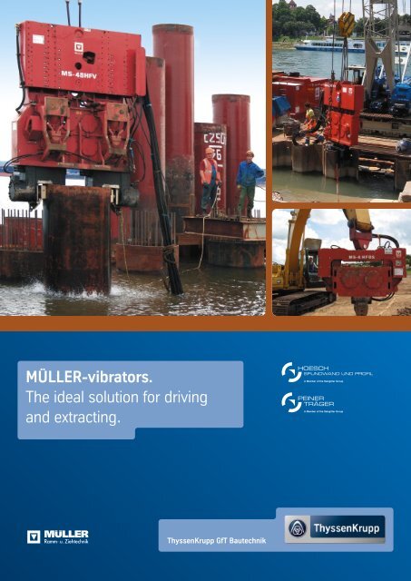
MÜLLER-vibrators.<br />
The ideal solution for driving<br />
and extracting.<br />
<strong>ThyssenKrupp</strong> GfT <strong>Bautechnik</strong><br />
HOESCH<br />
SPUNDWAND UND PROFIL<br />
PEINER<br />
TRÄGER
02 | 03 Contents.<br />
Integrated services.<br />
MÜLLER vibrators.<br />
MÜLLER excavator-mounted vibrators.<br />
MÜLLER leader-mounted vibrators. MÜLLER drill drives.<br />
MÜLLER power packs and control system.<br />
MÜLLER clamping devices and safety grippers.<br />
MS – EDGR. (MÜLLER System – Electronic Data Geological Report).<br />
Special equipment.<br />
3<br />
4 - 13<br />
14 - 16<br />
17<br />
18<br />
19<br />
20 - 21<br />
22 - 23
Integrated services.<br />
For driving and extracting.<br />
Using the right machinery and equipment is the key to cost-effective pile driving and<br />
extracting. As an integrated supplier we provide not only the piling materials but also the<br />
required hardware to meet all technical and environmental requirements.<br />
Machines for port and civil engineering solutions.<br />
<strong>ThyssenKrupp</strong> GfT <strong>Bautechnik</strong> has many years of experience in all areas of<br />
port and special civil engineering.<br />
Our specialists operate around the world, applying the very latest methods and<br />
technologies. They analyze all relevant parameters to determine the ideal machines<br />
for customer projects and thus ensure the highest levels of cost-efficiency.<br />
Our strengths. Our philosophy.<br />
Tailored, project-oriented solutions<br />
Specialist applications advice<br />
Worldwide availability of our machinery<br />
Recognized reliable service<br />
High-quality products<br />
Our service in detail.<br />
Sheet piling and sheet pile structures as system solutions for securing excavations<br />
and for use in port and canal construction projects. Steel piles as foundations for<br />
port and bridge structures, industrial buildings and high-rises.<br />
Driving, extracting, drilling and impacting equipment, quiet and powerful, even in<br />
extreme conditions, therefore particularly kind to the environment.<br />
�<br />
Anchor equipment for all soils and rock for the highest possible safety standards.<br />
�<br />
Interchangeable modular elements for the reliable securing of trenches and shafts.<br />
Trench sheeting sections, strong frame and trench box systems, lightweight aluminum<br />
trench boxes and trench struts.<br />
Flood protection: permanent TKR glass wall system, sheet pile walls and temporary<br />
TKR aluminum stop log system, fold-up systems, structures for waterproofing doors<br />
and windows.<br />
Construction machinery and equipment such as hydraulic hammers, demolition cutters,<br />
pipe pullers, cutters, compressors, soil compactors and sand removal equipment.<br />
System solutions from a single source. For us, that means making<br />
our success your success to guarantee high customer satisfaction.
04 | 05 MÜLLER vibrators.<br />
Specialists for driving and extracting technology.<br />
Driving and extracting are central construction tasks. Customer requirements in this<br />
area are rightly high as in addition to the project-related technical conditions, aspects<br />
such as cost efficiency and environmental impact play an important part.<br />
!<br />
Our strengths – your advantages.<br />
We offer:<br />
24-hour emergency service<br />
24-hour spare part service<br />
The principle of vibratory pile driving. Advantages of MÜLLER vibrators.<br />
Vibratory pile driving is based on the principle of<br />
converting the soil to a quasi-fluid state. This is<br />
achieved by vibrating the pile as it impacts the soil.<br />
Surface friction on the pile is reduced significantly<br />
by the vibrations, permitting rapid rates of penetration.<br />
For the correct selection of a vibrator, parameters<br />
such as soil condition, piling weight, length and<br />
shape, and the pile driving location playing a major<br />
role.<br />
Centrifugal force and eccentric moment are fundamental<br />
parameters for classifying an application.<br />
Together they overcome the friction between pile<br />
and soil.<br />
and lots more.<br />
MÜLLER vibrators meet high quality requirements.<br />
They are user-friendly, low-maintenance and longlasting.<br />
For almost every application there is a tailored<br />
solution, including free-riding systems, excavator-mounted<br />
vibrators and leader-mounted units.<br />
Compared with other techniques, MÜLLER machines<br />
are low on noise emissions and vibrations.<br />
The heart of each vibrator is the exciter block. It is<br />
fitted with counter-rotating eccentrics mounted in<br />
pairs in special heavy-duty bearings. A spring<br />
suspension unit located at the head of the vibrator<br />
absorbs the vibrations generated in the exciter<br />
block, isolating them from the carrier.<br />
MÜLLER vibrators with resonance-free starting and<br />
infinitely variable amplitude as well as “two-in-one”<br />
vibrators with stepwise variable eccentric moment<br />
and frequency offer advantages in that they can be<br />
adapted to suit different working conditions.
The<br />
M = G . r<br />
ideal combination.<br />
Proven vibrators with state-of-the-art technology.<br />
MÜLLER vibrators have a proven track record in civil engineering stretching back more than<br />
50 years. As leading-edge vibratory products they meet all market requirements. Suitable<br />
for a wide range of applications, their reliability and constant development make them a<br />
relevant market factor.<br />
How MÜLLER vibrators work.<br />
MÜLLER vibrators with fixed eccentric moment (H series).<br />
The vibrators are fitted with eccentrics which generate a fixed eccentric<br />
moment. For continuous use or use in extreme climatic conditions,<br />
vibrators can be equipped with a forced lubrication system including<br />
oil cooling (H3 series).<br />
High-frequency MÜLLER “two in one” vibrators with stepwise<br />
variable eccentric moment (HHF series).<br />
The vibrators in the HHF series are suitable for a broad range of applications.<br />
The eccentric moment can be increased or reduced in steps<br />
by adding/removing additional weights, allowing one vibrator to<br />
achieve different amplitudes and frequencies. Very high eccentric<br />
moments of up to 190 kgm can be generated.<br />
Principle of resonance-free starting and stopping.<br />
Vibrator<br />
with variable<br />
eccentric<br />
moment<br />
Vibrator<br />
with fixed<br />
eccentric<br />
moment<br />
2000<br />
1000<br />
0<br />
Ground vibration<br />
Ground vibration<br />
Frequency<br />
Starting phase<br />
Resonance frequencies<br />
Excess vibration<br />
Operating time<br />
Driving / extracting time<br />
Total operating cycle time<br />
High-frequency MÜLLER vibrators with variable eccentric<br />
moment (HFV series)<br />
When starting these vibrators, the eccentrics are arranged in such as<br />
way as to mutually balance out the centrifugal forces they generate<br />
and thus prevent any vibration. Once the required frequency has<br />
been reached, the eccentrics are turned counter to each other so<br />
that the centrifugal forces act in the same direction and generate<br />
vibration. This makes it possible to avoid passing through the resonance<br />
frequency of the soil (approx. 10 to 25 Hz depending on soil<br />
type) during starting and stopping.<br />
Resonance frequencies<br />
Stopping<br />
t<br />
t<br />
t<br />
The operating cycle can be broken down into<br />
three phases: the starting phase, the working<br />
phase and the stopping phase. The starting<br />
and stopping phases are similar in terms of<br />
vibration propagation in the soil. With a nonvariable<br />
eccentric moment, the machine<br />
passes through the soil's resonant frequency<br />
during starting and stopping.<br />
This causes the ground around the driving<br />
area to oscillate and reinforces the vibrations.<br />
This is represented by vibration peaks. If the<br />
arrangement of the eccentrics is varied during<br />
starting and stopping, the counter-rotating<br />
eccentrics balance each other out, eliminating<br />
the resonance. The settings of the eccentrics<br />
are changed when a target frequency is<br />
reached. Vibrations are only transferred into<br />
the soil by the pile during the working phase.<br />
The difference between the natural frequency<br />
range of the soil and that of the vibrator is so<br />
great that the transfer of vibrations is minimized.<br />
The spring suspension unit is activated<br />
and absorbs the vibrations that could be<br />
transferred to the carrier.
06 | 07 Ensuring top performance.<br />
Parameters, equipment selection and operating principle.<br />
Choosing the right equipment is key to the economic and technical success of any vibration<br />
driving job. Parameters such as the size and drive output of the vibrator must be matched to<br />
the length and weight of the pile and the soil conditions.<br />
Vibrator selection. Important details.<br />
The graphic below provides help in determining the required centrifugal<br />
force or in selecting the right vibrator based on soil conditions, pile<br />
weight and driving depth. Mark a point on the left-hand side of the<br />
table representing the maximum driving depth, and another point on<br />
the right-hand side marking the maximum pile weight.<br />
At the point where this line crosses the soil data line for your project,<br />
draw a vertical line to the vibrator models. This provides an overview<br />
of the units which can be considered for your requirements. This<br />
service offers an orientation guide; however, selections should always<br />
be confirmed by specialists.<br />
To determine the exact model, we can offer competent advice taking<br />
account of site-specific, geological and technical requirements.<br />
Model<br />
5<br />
10<br />
15<br />
20<br />
25<br />
30<br />
35<br />
40<br />
45<br />
50<br />
MS-10 HFV 16 HFV MS-24 HFV MS-32 HFV MS-48 HFV<br />
MS-5 HFBV MS-25 H2/H3<br />
MS-10/17 HF (B)<br />
200<br />
400<br />
600<br />
MS-25 HHF<br />
MS-50 H2/H3<br />
Key vibration technology data.<br />
Choosing the right vibrator for the job mainly depends on pile size,<br />
driving depth and soil conditions. The greater the driving depth and<br />
the harder or more compact the soil, the higher the centrifugal force<br />
and amplitude required. Centrifugal force and amplitude need to be<br />
high enough to overcome the surface friction and tip resistance<br />
between the pile and the surrounding soil. Key vibrator data in this<br />
context are shown in the following descriptions and formulae.<br />
MS-62 HFV<br />
MS-50 HHF MS-100 HHF<br />
For high-frequency vibrator applications, the centrifugal forces<br />
determined in this way should be 30% higher.<br />
Use of additional aids such as flushing pipes or preparatory drilling<br />
can significantly increase the driving performance of a vibrator.<br />
800 1000 1200 1400 1600 1800 2000 2200 2400 2600 2800 3000 3200 3400 3600 3800 4000<br />
G<br />
loose soil<br />
very dense soil (clay)<br />
dense soil<br />
medium-dense soil<br />
MS-120 HHF MS-200 HHF<br />
Centrifugal force kN Centrifugal force kN<br />
Driving depth [m]<br />
Example<br />
Weight of double pile: 3.0 t<br />
Driving depth: 17 m<br />
Vibrator selected for mediumdense<br />
soil = MS-50 HHF<br />
1<br />
r<br />
2<br />
3<br />
4<br />
5<br />
6<br />
7<br />
8<br />
9<br />
10<br />
11<br />
12<br />
Pile weight [t]
Key vibration technology data.<br />
Eccentric moment<br />
M [kgm] The eccentric moment is the meas-<br />
.<br />
M = G r<br />
Speed (frequency) n [rpm]<br />
.<br />
2<br />
F = M w<br />
Operating principle of Müller vibrators (typical design).<br />
Power pack Diesel-hydraulic<br />
ure of unbalance. As a determining<br />
factor for amplitude it is a key<br />
parameter for driving operations.<br />
The speed dictates the vibration frequency of the system. The vibrations are<br />
transferred via the pile to the surrounding soil, significantly reducing the surface<br />
friction between pile and soil. High frequencies counter the unwanted spread of<br />
vibrations in the soil.<br />
Centrifugal force<br />
F [N]<br />
G<br />
r<br />
F = M (p . n<br />
)<br />
30<br />
2<br />
The centrifugal force must be high enough to<br />
overcome surface friction between pile and soil.<br />
Centrifugal force plays a major part in reducing<br />
surface friction and provides impact force to<br />
overcome tip resistance.<br />
Remote control<br />
Elastic hose bracket<br />
Hydraulic power hoses<br />
Total amplitude S [m]<br />
S = 2s =<br />
.<br />
2 Mstat<br />
Gdyn<br />
[kgm]<br />
[kg]<br />
Together with centrifugal force, amplitude is a measure of driving performance. A large<br />
“stroke” and high “impact force” ensure good driving progress. When driving and<br />
extracting in cohesive soils, the elastic connection between pile and soil can only be<br />
broken if the amplitude is high enough.<br />
2<br />
Acceleration a [m/sec ]<br />
2<br />
a s w<br />
=<br />
.<br />
with<br />
w = p . n<br />
30<br />
Transmission of the pile acceleration to the surrounding soil causes the displacement<br />
of the particle structure and reduces particle friction and soil resistance.<br />
Acceleration is indicated as the ratio of acceleration to gravity:<br />
w = a<br />
g<br />
This ratio corresponds to:<br />
The value can lie between 10 and 30.<br />
Drive output P [kW]<br />
h<br />
F . 10<br />
=<br />
Gdyn<br />
The drive unit must be powerful enough to generate the moment needed to maintain<br />
the centrifugal force of the vibrator, even in difficult ground. The drive output should<br />
be 2 kW per 10 kN centrifugal force.<br />
Suspension<br />
Vibration isolator<br />
(spring suspension unit)<br />
Motor<br />
Eccentric<br />
Exciter block<br />
Hydraulic<br />
clamping<br />
device<br />
Pile<br />
-1<br />
Gdyn
08 | 09<br />
Vibrator<br />
Centrifugal force<br />
Eccentric moment<br />
Speed<br />
Frequency<br />
Pulling force<br />
Weight (dynamic)<br />
Weight (total)<br />
Amplitude<br />
Displacement<br />
Pressure<br />
Power consumption<br />
Dimensions<br />
Power pack<br />
Single clamping device<br />
Double clamping device<br />
Müller vibrators.<br />
H series with fixed eccentric moment.<br />
The vibrators in this series are extremely robust and suitable for<br />
driving in loose to medium-dense soils. The “stretched” base plate<br />
in particular is ideal for driving and extracting pipes for in-situ<br />
concrete piles. The clamping devices on the base plate can be<br />
steplessly adjusted to allow a simple changeover to different pipe<br />
diameters on site.<br />
Fixed eccentric moment.<br />
Centrifugal force<br />
F<br />
F (max.)<br />
M stat<br />
n (max.)<br />
f (max.)<br />
F pull (max.)<br />
without clamping device<br />
without clamping device<br />
without clamping device/pile<br />
Q Motor (max.)<br />
p (max.)<br />
p (max.)<br />
Length L<br />
Width B<br />
Height H<br />
Throat T<br />
Type<br />
alternative Type<br />
Type<br />
alternative Type<br />
F limit<br />
kN<br />
kgm<br />
rpm<br />
Hz<br />
kN<br />
kg<br />
kg<br />
mm<br />
l/min<br />
bar<br />
kW<br />
mm<br />
mm<br />
mm<br />
mm<br />
MS-A<br />
MS-U<br />
MS-U<br />
MS-U<br />
MS-U<br />
MS-25 H2<br />
774<br />
25<br />
1680<br />
28.0<br />
400<br />
1930<br />
3200<br />
25.9<br />
425<br />
350<br />
248<br />
2200<br />
681<br />
1685<br />
402<br />
260<br />
100<br />
150<br />
2 x 54<br />
MS-25 H3<br />
774<br />
25<br />
1680<br />
28.0<br />
400<br />
2550<br />
3600<br />
19.6<br />
425<br />
350<br />
248<br />
2200<br />
777<br />
1745<br />
402<br />
260<br />
100<br />
150<br />
2 x 54<br />
MS-35 H3<br />
834<br />
32.5<br />
1530<br />
25.5<br />
400<br />
2660<br />
3600<br />
24.4<br />
463<br />
350<br />
270<br />
2200<br />
777<br />
1745<br />
402<br />
260<br />
100<br />
150<br />
54<br />
2 x 90/100<br />
MS-50 H2<br />
1430<br />
50<br />
1615<br />
26.9<br />
500<br />
3340<br />
6300<br />
29.9<br />
719<br />
350<br />
419<br />
2600<br />
696<br />
2035<br />
450<br />
420<br />
180<br />
150<br />
2 x 90<br />
2 x 100<br />
MS-50 H3<br />
1430<br />
50<br />
1615<br />
26.9<br />
500<br />
3820<br />
8050<br />
26.2<br />
719<br />
350<br />
419<br />
2800<br />
722<br />
2105<br />
490<br />
420<br />
180<br />
-<br />
2 x 90<br />
2 x 100<br />
n limit<br />
n<br />
speed<br />
MS-65 H3<br />
1670<br />
65<br />
1530<br />
25.5<br />
500<br />
4200<br />
8200<br />
31.0<br />
680<br />
350<br />
397<br />
2800<br />
737<br />
2105<br />
520<br />
420<br />
200<br />
250<br />
100
Driving of 2.65 m diameter pipes weighing<br />
100 to 160 tons for Germany's first offshore<br />
wind project. To ensure verticality, the first<br />
meters were driven with an MS-200 HHF and<br />
a special bracket to which the clamps were<br />
mounted. The pipe was sunk to final depth<br />
with a hydraulic hammer. Vibratory driving<br />
can be used for a wide variety of wind<br />
turbine foundation designs.<br />
MÜLLER vibrators in action.<br />
Project alpha ventus.<br />
Pioneering achievement on the high seas.<br />
Source: Alpha Ventus Press picture
10 | 11<br />
alpha ventus.<br />
A world first: electricity from wind power on the high seas.<br />
Wind farms have been set up in shallow waters around the coasts<br />
of Denmark, Sweden, the Netherlands and Great Britain. But the<br />
first German wind farm, “alpha ventus”, is being built in 30 m of<br />
water some 45 km north of the island of Borkum.<br />
This marks the beginning of a new era in wind energy. The 12 turbines<br />
of this wind farm, each with an output of 5 MW, will eventually supply<br />
electricity for about 50,000 people. The first wind turbine was completed<br />
on 15 July 2010. The intention is to install about 10,000 MW of<br />
power in German waters by 2020 ‒ up to 25 000 MW in total. The<br />
offshore wind turbines are connected to a transformer station at the<br />
south-east corner of the wind farm, from where a 16 cm underwater<br />
cable connects them to the onshore electricity grid.<br />
Facts & figures.<br />
Client<br />
EWE, E.ON, Vattenfall<br />
Detailed engineering design<br />
DOTI GmbH<br />
Contractor<br />
Multibrid GmbH<br />
The construction of the alpha ventus wind farm represents a whole new,<br />
daring chapter for the energy sector.<br />
Plant<br />
MS-200 HHF<br />
Centrifugal force 4,000 kN<br />
Eccentric moment 190 kgm<br />
with incremental moment adjustment<br />
Piles<br />
Length 40.00 m<br />
Weight approx. 110 to<br />
Diameter 2.650 m<br />
Driving depth approx. 10 m by vibration<br />
Driving to design depth impact-driving with<br />
hydraulic hammer<br />
A challenge for people and materials.<br />
Just the dimensions alone are staggering: The hub of each turbine is<br />
90 m above sea level. And added to that is another 30 m below water,<br />
down to the seabed. Including the rotor blades, the total height of a<br />
wind turbine is about 155 m, almost as high as Cologne Cathedral. In<br />
the North Sea wind speeds can reach 90 kmh, and in such weather<br />
huge waves are normal. Wind and weather dictate timetables and<br />
place great demands on crews and equipment.<br />
The extreme ambient conditions were a constant concern during the<br />
planning of the alpha ventus project ‒ for both the construction and<br />
service phases. Therefore, meteorologists, with the help of satellites,<br />
observe and analyse the weather situation constantly during the<br />
construction work. Before the project started, the <strong>ThyssenKrupp</strong> GfT<br />
Tiefbautechnik installation personnel from Alsfeld had to undergo the<br />
safety training for work on offshore platforms and are now available<br />
for all projects concerned with wind power installations.<br />
The customer benefited because that meant 24-hour on-site services<br />
– necessary in order to complete the project within the very small time<br />
slot allocated.
AV1<br />
Precision work between storms and waves: vibration technology.<br />
Wind farms require secure foundations which place high demands on dimensional accuracy and other<br />
factors. Deployment under difficult weather conditions at sea, deployment underwater and relatively<br />
low-noise plant are just some of the advantages of vibration technology. More than 60 wind turbines<br />
are planned for the North Sea alone in the coming years. The good properties of steel make it an<br />
ideal material for building such installations.<br />
The alpha ventus transformer station is founded on four tubular steel piles which support a tubular<br />
steel tower. In this project the piles were vibratory driven down to a depth of 10 m with an MS-200<br />
HHF vibrator. Final driving of the piles was carried out with a hydraulic hammer in order to be able<br />
to calculate the load-bearing capacity. This was the first time that vibration technology had been<br />
used successfully in an offshore project. To achieve this pioneering performance, <strong>ThyssenKrupp</strong> GfT<br />
Tiefbautechnik tapped its vast stock of knowledge gained from recent projects involving underwater<br />
foundations for port facilities.<br />
The foundation to the alpha ventus transformer station makes use of four tubular steel piles, each<br />
approx. 40 m long and weighing up to 110 t. The subsoil here consists of dense to very dense sand<br />
strata. The combination of vibration and impact-driving enabled several conditions to be fulfilled. After<br />
detaching the transport apparatus, the vibrator could be supported directly on the steel pile, thus<br />
holding and aligning it. A mounting bracket with two clamp grips was used to transfer the force of the<br />
vibrator to the pile. Consequently, neither a costly and elaborate guiding frame nor an apparatus for<br />
suspending the pile were necessary.<br />
That in turn saved space on the already very congested installation platform and the vertical alignment<br />
of the pile could be achieved with simple means. A pile-mounted vibrator results in simple<br />
vertical installation, an optimum, fast driving time and extremely good economics, too.<br />
The amount of steel used in a wind turbine structure is about 1000 t, which corresponds to the weight<br />
of 200 fully grown elephants or 22 railway carriages! The rotor catches the wind from an area roughly<br />
equal to one-and-a-half football pitches. At maximum r.p.m., the tips of the rotor blades are cutting<br />
through the air at almost 320 kmh! It is quite obvious that anchoring this installation securely to the<br />
seabed is a major challenge. Once the transformer station had been constructed, six wind turbines<br />
were erected on foundations comprising so-called tripods – frameworks anchored to the seabed by<br />
means of steel piles. In this project three piles were driven into the seabed per tripod with the help of<br />
MÜLLER vibration technology. The tubular steel piles weigh approx. 130‒160 t each – even heavier<br />
than those below the transformer station.<br />
Germany is among the leaders in terms of worldwide sales of renewable energy (wind turbines and<br />
photovoltaic systems in operation). Renewable energy now accounts for about 10% of total energy<br />
requirements in Germany, and just over 15% of the electricity consumption. Some 280,000 people<br />
are employed in the manufacture of wind turbines and solar power installations, in biomass or<br />
geothermal energy power plants. This industry is evolving into an important growth sector of the<br />
German economy.<br />
Source: Alpha Ventus Press picture
12 | 13 Müller “two in one” vibrators.<br />
HHF series with stepwise variable eccentric<br />
moment – two in one.<br />
Vibrator<br />
Centrifugal force<br />
Eccentric moment<br />
Steps<br />
Speed steps<br />
Frequency steps<br />
Pulling force<br />
Weight (dynamic)<br />
Weight (total)<br />
Amplitude<br />
Displacement<br />
Pressure<br />
Power consumption<br />
Dimensions<br />
Power pack<br />
Single clamping device<br />
Double clamping device<br />
*Combination for increased performance<br />
The vibrator can be adapted quickly to different soil conditions by a simple system of<br />
adding or removing weights, allowing the eccentric moment to be varied. For example, if<br />
high frequency is required for work in loose sand, the additional weights can be removed<br />
simply on site to achieve high frequencies with the same centrifugal force.<br />
F (max.) kN<br />
M stat (max.) kgm<br />
kgm<br />
n (max.) rpm<br />
f (max.) Hz<br />
F pull (max.) kN<br />
without clamping device kg<br />
without clamping device kg<br />
without clamping device/pile mm<br />
Q Motor (max.) l/min<br />
p (max.) bar<br />
P (max.) kW<br />
Length L mm<br />
Width B mm<br />
Height H mm<br />
Throat T mm<br />
MS-A<br />
MS-U<br />
alternative MS-U<br />
MS-U<br />
alternative MS-U<br />
Stepwise variable moment.<br />
F<br />
Centrifugal force F limit<br />
MS-25 HHF<br />
750<br />
25<br />
12/15/20/25<br />
2170/2113/1830/1637<br />
39.3/35.2/30.5/27.3<br />
280<br />
2900<br />
3700<br />
8.3/10.3/13.8/17.2<br />
470<br />
350<br />
274<br />
1800<br />
813<br />
1885<br />
360<br />
260<br />
90<br />
100<br />
2 x 54<br />
2 x 70<br />
MS-50 HHF<br />
420 570*<br />
180<br />
200<br />
2 x 90<br />
2 x 100<br />
MS-100 HHF<br />
2 x 150<br />
2 x 180<br />
MS-120 HHF<br />
2 x 180<br />
M stat >M stat >M stat >M stat<br />
n limit<br />
n<br />
speed<br />
MS-200 HHF<br />
1500<br />
2500<br />
3003<br />
4000<br />
50<br />
100<br />
116<br />
190<br />
24/30/40/50 48/60/80/100 80/94/110/116 (98)/110/115/190<br />
2362/2113/1830/1637 2160/1920/1670/1500 1850/1700/1570/1536 (1800)/1800/1560/1371<br />
39.3/35.2/30.5/27.3 36/32/27.8/25 30.9/28.3/26.2/25.6 30/26/22.9<br />
500<br />
600<br />
1200<br />
1200<br />
4500<br />
7700<br />
8900<br />
11750<br />
6100<br />
10900<br />
15500<br />
18500<br />
10.7/13.3/17.8/22.2 12.5/15.6/20.8/26.0 18.0/21.1/24.7/26.1 16.7/18.7/25.5/32.4<br />
610 964<br />
1045 1286<br />
989 1150 1534 1435 1680<br />
350<br />
350<br />
350<br />
350<br />
356 562<br />
610 750<br />
577 671 895 837 980<br />
2260<br />
2410<br />
2300<br />
2300<br />
888<br />
843<br />
1200<br />
1430<br />
2465<br />
3235<br />
4135<br />
4170<br />
350<br />
660<br />
832<br />
832<br />
700 840*<br />
840 1050*<br />
840 1050*<br />
360<br />
360<br />
2 x 250
Vibrator<br />
Centrifugal force<br />
Eccentric moment<br />
Speed<br />
Frequency<br />
Pulling force<br />
Weight (dynamic)<br />
Weight (total)<br />
Amplitude<br />
Power consumption<br />
Displacement<br />
Pressure<br />
Dimensions<br />
Power pack<br />
Single clamping device<br />
Double clamping device<br />
*Combination for increased performance<br />
F = 100 %<br />
F = 75 %<br />
F = 0 %<br />
MÜLLER vibrators.<br />
HFV series with variable frequency and amplitude for resonancefree<br />
starting and stopping.<br />
The need to avoid vibration and noise emissions e.g. on inner-city sites is becoming<br />
increasingly important. Our range of state-of-the-art variable vibrators with resonance-free<br />
starting and stopping was designed specially for this. These machines deliver exceptional<br />
performance while minimizing noise and vibrations. They allow frequency and amplitude to<br />
be matched optimally to the soil conditions. The precision programmable controller enables<br />
several functions to be combined and carried out with just one command. The controller<br />
can also be set so that frequency does not fall below a preselected level.<br />
F (max.)<br />
M stat (variable)<br />
n (max.)<br />
f (max.)<br />
F pull (max.)<br />
without clamping device<br />
without clamping device<br />
without clamping device/pile<br />
P (max.)<br />
Q Motor (max.)<br />
p (max.)<br />
Length L<br />
Width B<br />
Height H<br />
Throat T<br />
Type<br />
alternativ<br />
Type<br />
alternativ<br />
kN<br />
kgm<br />
rpm<br />
Hz<br />
kN<br />
kg<br />
kg<br />
mm<br />
kW<br />
l/min<br />
bar<br />
mm<br />
mm<br />
mm<br />
mm<br />
MS-A...V<br />
MS-U<br />
MS-U<br />
MS-U<br />
MS-U<br />
Variable eccentric moment.<br />
Centrifugal force<br />
F<br />
MS-10 HFV<br />
610<br />
0 – 10<br />
2358<br />
39.3<br />
180<br />
1700<br />
2300<br />
11.8<br />
147 203<br />
253 348<br />
350<br />
1635<br />
732<br />
1530<br />
330<br />
170 260*<br />
MS-U 72<br />
MS-U 100<br />
2 x 54<br />
2 x 70<br />
MS-16 HFV<br />
968<br />
0 – 16<br />
2350<br />
39.2<br />
300<br />
2600<br />
3500<br />
12.3<br />
220 294<br />
378 504<br />
350<br />
1930<br />
757<br />
2010<br />
350<br />
260 420*<br />
MS-U 150<br />
2 x 70<br />
2 x 90<br />
F limit<br />
MS-20 HFV<br />
1230<br />
0 – 19.5<br />
2400<br />
40.0<br />
300<br />
2530<br />
3600<br />
15.4<br />
413<br />
708<br />
350<br />
2080<br />
782<br />
2060<br />
350<br />
420<br />
MS-U 150<br />
2 x 90<br />
2 x 100<br />
MS-24 HFV<br />
1480<br />
0 – 24<br />
2350<br />
39.2<br />
400<br />
2900<br />
5050<br />
16.5<br />
404 551<br />
693 945<br />
350<br />
1920<br />
893<br />
2145<br />
451<br />
420 570*<br />
MS-U 180<br />
2 x 90<br />
2 x 100<br />
MS 28 HFV<br />
1473<br />
0 – 28<br />
2190<br />
36.5<br />
500<br />
3120<br />
5320<br />
18.0<br />
428 514<br />
734 880<br />
350<br />
1920<br />
893<br />
2240<br />
451<br />
420 570*<br />
MS-U 180<br />
2 x 90<br />
2 x 100<br />
Variable speed gears<br />
MS-32 HFV<br />
1980<br />
0 – 32<br />
2375<br />
39.6<br />
600<br />
4850<br />
7250<br />
13.2<br />
570 685<br />
1045 1175<br />
350<br />
2371<br />
800<br />
2455<br />
345<br />
570 700*<br />
MS-U 250<br />
2 x 150<br />
NEW!<br />
MS-40 HFV<br />
2006<br />
0 – 39.2<br />
2160<br />
36.0<br />
600<br />
4870<br />
7280<br />
16.1<br />
630 756<br />
1080 1296<br />
350<br />
2371<br />
880<br />
2455<br />
345<br />
700 840*<br />
MS-U 250<br />
2 x 150<br />
2 x 180<br />
MS-48 HFV<br />
2960<br />
0 – 48<br />
2350<br />
39.0<br />
600<br />
6520<br />
9700<br />
14.7<br />
682 823<br />
1170 1410<br />
350<br />
2371<br />
1123<br />
2525<br />
860<br />
700 840*<br />
MS-U 360<br />
2 x 180<br />
n limit<br />
MS-62 HFV<br />
2998<br />
0 – 62<br />
2100<br />
35.0<br />
800<br />
6805<br />
11165<br />
18.2<br />
980 735<br />
1680 1260<br />
350<br />
2371<br />
1180<br />
2525<br />
860<br />
1050<br />
MS-U 360<br />
2 x 180<br />
n<br />
speed
14 | 15 MÜLLER excavator-mounted vibrators.<br />
Powerful, compact, user-friendly and reliable.<br />
w = a<br />
g<br />
Excavator-mounted vibrators can be used to perform general driving,<br />
extracting and compacting work (MS-2 HFB to MS-7 HFB). With a<br />
modified clamp arrangement the vibrators MS-4 HFB, MS-6 HFB and<br />
MS-7 HFB are suitable for pipe driving. Jobs in vibration-sensitive or<br />
inner-city areas are carried out reliably with the vibrators MS-5 HFBV<br />
and MS-8 HFBV, which feature resonance-free starting and stopping.<br />
The MS-1 HFB was specially designed for installing plastic sheet piles,<br />
wooden piles and lightweight sections. The high-performance vibrators<br />
MS-9 HFB and MS-17 HFB are needed for jobs in heavy soils.<br />
Excavator-mounted vibrators are<br />
fitted to the excavator stick by<br />
means of a connecting fork. We<br />
offer forks matched to your excavator.<br />
A rotary joint allows easy<br />
alignment of the vibrator with the<br />
piling. The high-strength push<br />
head allows additional forces to<br />
be applied from the excavator to<br />
the vibrator, boosting driving performance.<br />
The vibrator is operated<br />
by the excavator “tilt stick”<br />
control.<br />
The vibrator is connected to the<br />
boom's hydraulic connections by<br />
two hoses. A third hose, the leak<br />
Vibratory pile driving is based on the principle of reducing the cohesion of soils through<br />
vibration, effectively fluidizing the soil. When the soil is in this condition, installing the piling<br />
requires only little force. The dead weight of the piling and the applied force are enough to<br />
drive the piling to the required depth quickly, quietly and efficiently. The same applies when<br />
extracting the piling. The required pulling force is minimized due to the reduced friction. The<br />
link between the piling and the vibrator is the clamping device, which forms a firm connec-<br />
tion and releases it again after driving.<br />
Applications. Selection.<br />
Mounting and operation.<br />
oil line, completes the simple hydraulic<br />
connection. Integrated in<br />
the vibrator is a control system<br />
that ensures that when the control<br />
lever in the excavator is swung<br />
out a clamp grips the pile firmly<br />
and then holds the clamping force<br />
constant at the required level. A<br />
governor limits rpm to the maximum<br />
allowed level – irrespective<br />
of the oil flow supplied by the excavator<br />
– and thus ensures longer<br />
vibrator life.<br />
Choosing the right vibrator for a job depends on soil conditions, the<br />
type of pile and the driving depth. The vibrator also has to be matched<br />
to the excavator (oil flow, pressure). If the excavator cannot supply<br />
enough power, the vibrators can be driven by separate MÜLLER<br />
hydraulic power packs. The vibrator is controlled conveniently by the<br />
excavator operator via remote control (cable or radio).<br />
The advantages at a glance.<br />
�Extremely low height allows driving of long piles<br />
�High push/pull forces increase driving performance<br />
�All vibrators are fitted with a safety circuit<br />
�All clamps can be rotated 90° to allow face working<br />
�Double clamping devices can be fitted for pipe driving<br />
�Simple mounting with three hoses<br />
�User-friendly design with one-lever operation<br />
�Long life<br />
An overview of the most common excavator types with their<br />
performance data and recommended vibrators is available online<br />
as a PDF file (www.thyssenkrupp-gft-tiefbautechnik.com).<br />
This service offers an orientation guide; however, selections should<br />
always be confirmed by specialists.
Type<br />
MÜLLER excavator-mounted vibrators.<br />
Overview of technical data.<br />
Centrifugal force<br />
F (max.)<br />
Eccentric moment<br />
M stat (max.)<br />
Frequency<br />
f (max.)<br />
Speed<br />
n (max.)<br />
Pulling force<br />
F pull (max.)<br />
Push down<br />
F push (max.)<br />
Power consumption<br />
Total weight (incl. clamping device)<br />
Dyn. weight (incl. clamping device)<br />
P (max.)<br />
Amplitude<br />
Displacement<br />
Length<br />
Width<br />
Height, incl. clamping device<br />
Width at throat<br />
Standard clamping device<br />
Recommended power pack<br />
Type<br />
Q Motor (max.)<br />
L<br />
B<br />
H<br />
T<br />
Centrifugal force<br />
F (max.)<br />
Eccentric moment<br />
M stat (max.)<br />
Frequency<br />
f (max.)<br />
Speed<br />
n (max.)<br />
Pulling force<br />
F pull (max.)<br />
Push down<br />
F push (max.)<br />
Power consumption<br />
Total weight (incl. clamping device)<br />
Dyn. weight (incl. clamping device)<br />
P (max.)<br />
Amplitude<br />
Displacement<br />
Length<br />
Width<br />
Height, incl. clamping device<br />
Width at throat<br />
Standard clamping device<br />
Recommended power pack<br />
Q Motor (max.)<br />
L<br />
B<br />
H<br />
T<br />
*Option: with three or five connecting hoses<br />
kN<br />
kgm<br />
Hz<br />
rpm<br />
kN<br />
kN<br />
kW<br />
kg<br />
kg<br />
mm<br />
l/min<br />
mm<br />
mm<br />
mm<br />
mm<br />
MS-U...<br />
MS-A...V<br />
kN<br />
kgm<br />
Hz<br />
rpm<br />
kN<br />
kN<br />
kW<br />
kg<br />
kg<br />
mm<br />
l/min<br />
mm<br />
mm<br />
mm<br />
mm<br />
MS-U...<br />
MS-A...V<br />
MS-1 HFB<br />
90<br />
0.7<br />
56<br />
3360<br />
34<br />
34<br />
60<br />
350<br />
230<br />
6.1<br />
102<br />
761<br />
472<br />
761<br />
230<br />
MS-U 12<br />
MS-17 HFB<br />
604<br />
17<br />
30<br />
1800<br />
140<br />
170<br />
158<br />
2208<br />
1453<br />
23.4<br />
270<br />
1386<br />
917<br />
1036<br />
340<br />
MS-U 72<br />
MS-A 170<br />
MS-2 HFB<br />
245<br />
2.2<br />
53.1<br />
3185<br />
60<br />
40<br />
61<br />
815<br />
570<br />
7.7<br />
105<br />
1024<br />
623<br />
1024<br />
260<br />
MS-U 40<br />
MS-5 HFBV*<br />
400<br />
0 - 5<br />
45<br />
2700<br />
120<br />
80<br />
95<br />
1580<br />
1130<br />
8.8<br />
162<br />
1423<br />
706<br />
1498<br />
440<br />
MS-U 60<br />
MS-A 110 V<br />
MS-3 HFB<br />
296<br />
3<br />
50<br />
3000<br />
60<br />
40<br />
70<br />
830<br />
585<br />
10.3<br />
120<br />
1024<br />
623<br />
1024<br />
260<br />
MS-U 40<br />
MS-8 HFBV*<br />
585<br />
0 - 8<br />
43<br />
2580<br />
150<br />
150<br />
165<br />
1815<br />
1295<br />
12.4<br />
283<br />
1460<br />
758<br />
1583<br />
409<br />
MS-U 72<br />
MS-A 170 V<br />
MS-4 HFB<br />
374<br />
4.2<br />
47.5<br />
2850<br />
120<br />
80<br />
100<br />
1230<br />
940<br />
8.9<br />
171<br />
1174<br />
742<br />
1249<br />
340<br />
MS-U 60<br />
MS-A 110<br />
MS-4 HFBS<br />
378<br />
4.2<br />
47.5<br />
2850<br />
120<br />
80<br />
100<br />
1360<br />
1110<br />
7.7<br />
171<br />
1175<br />
697<br />
1250<br />
–<br />
MS-U 60<br />
MS-A 110<br />
MS-6 HFB<br />
464<br />
6.5<br />
42.5<br />
2550<br />
120<br />
80<br />
119<br />
1240<br />
950<br />
13.7<br />
204<br />
1174<br />
742<br />
1249<br />
340<br />
MS-U 60<br />
MS-A 110<br />
MS-6 HFBS<br />
464<br />
6.5<br />
42.5<br />
2550<br />
120<br />
80<br />
119<br />
1370<br />
1120<br />
11.6<br />
204<br />
1175<br />
697<br />
1250<br />
–<br />
MS-U 60<br />
MS-A 110<br />
MS-7 HFB<br />
604<br />
7<br />
46.7<br />
2800<br />
150<br />
80<br />
130<br />
1300<br />
950<br />
14.7<br />
224<br />
1174<br />
742<br />
1249<br />
340<br />
MS-U 72<br />
MS-A 170<br />
MS-9 HFB<br />
606<br />
8.5<br />
42.5<br />
2550<br />
150<br />
80<br />
133<br />
1380<br />
990<br />
17.2<br />
229<br />
1174<br />
742<br />
1249<br />
340<br />
MS-7 HFBS<br />
604<br />
7<br />
46.7<br />
2800<br />
150<br />
80<br />
130<br />
1380<br />
1130<br />
12.4<br />
224<br />
1175<br />
697<br />
1250<br />
–<br />
MS-U 72<br />
MS-A 110<br />
MS-U 72<br />
MS-A 170
16 | 17<br />
MÜLLER excavator-mounted vibrators.<br />
Products for special uses.<br />
The variable-moment excavator-mounted vibrators MS-5 HFBV and MS-8 HFBV with resonance-<br />
free starting and stopping are designed primarily for inner-city use and particularly vibration-<br />
sensitive projects. To adjust the eccentrics for resonance-free starting and stopping, a further<br />
excavator function, “rotate grab”, is necessary in addition to “tilt stick”.<br />
For this, the vibrator is connected to the excavator<br />
stick with two additional hoses.<br />
The patented control system on the variablemoment<br />
vibrators of the series HFBV3 allows<br />
a simple hydraulic connection with three hoses<br />
and simplified “one-lever operation” from the<br />
excavator, similar to conventional vibrators.<br />
The MS-1 HFB was developed specifically for<br />
installing plastic sheets and piles.<br />
Its applications lie in the construction of waterfront<br />
structures and jetties. It can be used to<br />
install wood and very small piles, soil nails and<br />
reinforcement cages for cast-in-situ piles.<br />
The MS-1 HFB can be mounted on mini or<br />
compact excavators upward of an installed rating<br />
of approx. 54 HP.<br />
Gsoil
Type<br />
Torque<br />
Speed<br />
Oil pressure<br />
Displacement<br />
Diameter<br />
Diameter<br />
Drill depth<br />
Drill depth<br />
Auger connection<br />
Weight<br />
*Options available on request<br />
MÜLLER leader-mounted vibrators.<br />
For attachment to leaders.<br />
MÜLLER drill drives.<br />
Various mounting options.<br />
D<br />
L<br />
SW<br />
MÜLLER leader-mounted vibrators in combination with proven variable moment control are<br />
ideal for driving and extracting steel sections such as pipes, sheet piles and beams and for use<br />
in foundation work such as the construction of compacted gravel or sand piles etc.<br />
They are slim enough to drive and extract small single piles and to work in tight conditions.<br />
Resonance-free starting and stopping protects both the surrounding area and the carrier from<br />
damaging vibrations and emissions.<br />
Type<br />
Centrifugal force<br />
Eccentric moment<br />
Speed<br />
Frequency<br />
Pulling force<br />
Total weight<br />
Dimensions<br />
Drilling equipment for mounting in vibrator clamping devices.<br />
Standard clamping device<br />
Low-noise, vibration-free drill drives from MÜLLER<br />
are available in three different mounting versions:<br />
Selecting the right drilling method allows pressurerelief<br />
and preparatory drilling to be carried out quickly<br />
and cost-efficiently, particularly in very dense soil.<br />
(max.)<br />
(max.)<br />
(max.)<br />
(max.)<br />
smallest drilling diameter<br />
largest drilling diameter<br />
with smallest drilling diameter (max.)<br />
with largest drilling diameter (max.)<br />
Standard distance across flats*<br />
without auger/without stand approx.<br />
on the guide slide of a leader<br />
in the clamp of a vibrator<br />
on the stick of an excavator<br />
Attachment to leader slide = 1<br />
Clamping in vibrator clamp = 2<br />
Connection to excavator stick = 3<br />
da Nm<br />
rpm<br />
bar<br />
l/min<br />
mm<br />
mm<br />
m<br />
m<br />
mm<br />
kg<br />
F (max.)<br />
M stat<br />
n (max.)<br />
f (max.)<br />
F pull (max.)<br />
incl. clamping device<br />
Height (incl. clamping device) H<br />
Throat T<br />
*The operating pressure for all leader-mounted vibrators is max. 350 bar.<br />
RHA 101<br />
RHA 102<br />
RHA 103<br />
1000<br />
125<br />
300<br />
260<br />
200<br />
700<br />
20<br />
4<br />
70<br />
300<br />
RHA 141<br />
RHA 142<br />
RHA 143<br />
1400<br />
115<br />
300<br />
350<br />
200<br />
900<br />
25<br />
4<br />
70<br />
360<br />
kN<br />
kgm<br />
rpm<br />
Hz<br />
kN<br />
kg<br />
mm<br />
mm<br />
MS-U<br />
MS-16 HFMV<br />
986<br />
0 - 16<br />
2376<br />
39.5<br />
180<br />
3980<br />
1710<br />
455<br />
150<br />
RHA 201<br />
RHA 202<br />
RHA 203<br />
2000<br />
110<br />
300<br />
460<br />
400<br />
1200<br />
14<br />
2<br />
80<br />
440<br />
RHA 281<br />
RHA 283<br />
2800<br />
100<br />
300<br />
600<br />
400<br />
1400<br />
16<br />
2<br />
100<br />
600<br />
MS-20 HFMV<br />
1160<br />
0 - 20<br />
2340<br />
38.4<br />
180<br />
4110<br />
1710<br />
455<br />
150<br />
RHA 401<br />
RHA 403<br />
4000<br />
70<br />
300<br />
600<br />
400<br />
1600<br />
20<br />
2<br />
120<br />
760
18 | 19 MÜLLER power packs and control system.<br />
Power supply: economical and ecological.<br />
Power packs<br />
Diesel motor<br />
Exhaust certification<br />
Exhaust certification<br />
Power<br />
Speed<br />
Hydraulics<br />
Feed rate<br />
Operating pressure<br />
Fuel tank capacity<br />
Hydraulic tank capacity<br />
Weight without fuel<br />
Dimensions:<br />
The energy supply to the vibrators is not only important from an economic point of view.<br />
Increasingly, questions of ecological compatibility are coming to the fore, e.g. energy<br />
efficiency and pollution through noise and CO emissions.<br />
2<br />
P (max.)<br />
n (max.)<br />
Q (max.)<br />
p (max.)<br />
Length L<br />
Width B<br />
Height H<br />
*optionally with variable amplitude<br />
ATAAC<br />
EU / EPA<br />
kW<br />
rpm<br />
l/min<br />
bar<br />
l<br />
l<br />
kg<br />
mm<br />
mm<br />
mm<br />
MS-A 110 (V)*<br />
CAT<br />
C 4.4<br />
IIIA / Tier 3<br />
106<br />
2200<br />
270<br />
380<br />
400<br />
250<br />
4000<br />
3000<br />
1400<br />
2100<br />
B<br />
MS-A 170 (V)*<br />
CAT<br />
C 6.6<br />
IIIA / Tier 3<br />
168<br />
2200<br />
310<br />
380<br />
400<br />
250<br />
4000<br />
3000<br />
1400<br />
2100<br />
H<br />
L<br />
The hydraulic vibrators are powered by power packs, in<br />
which diesel engine-driven hydraulic pumps deliver a flow<br />
of pressurized oil to the hydraulic motors on the vibrator.<br />
All power packs are silenced and are controlled by a specially<br />
adapted programmable controller and constantly monitored<br />
during operation.<br />
The vibrator is operated via a cable remote control, or optionally<br />
by radio remote control. The operating parameters of the<br />
vibrator can be monitored via an online connection. Should a<br />
problem occur, our experts can analyze the operating parameters<br />
and provide immediate assistance by phone.<br />
MS-A 260 (V)* MS-A 420 (V)* MS-A 570 (V)* MS-A 700 (V)* MS-A 840 (V)* MS-A 1050 (V)*<br />
CAT<br />
C 9<br />
IIIA / Tier 3<br />
261<br />
2200<br />
525<br />
380<br />
550<br />
250<br />
5000<br />
3700<br />
1490<br />
2340<br />
CAT<br />
C 15<br />
IIIA / Tier 3<br />
433<br />
2000<br />
740<br />
380<br />
900<br />
280<br />
6200<br />
4250<br />
1700<br />
2435<br />
CAT<br />
C 18<br />
IIA / Tier 2<br />
571<br />
1800<br />
1050<br />
380<br />
1050<br />
440<br />
8500<br />
4750<br />
2000<br />
2360<br />
2 x CAT<br />
C 13<br />
IIIA / Tier 3<br />
708<br />
2100<br />
1180<br />
380<br />
1400<br />
500<br />
10300<br />
4800<br />
2200<br />
2430<br />
2 x CAT<br />
C 15<br />
IIIA / Tier 3<br />
866<br />
2100<br />
1480<br />
380<br />
2200<br />
600<br />
12500<br />
5300<br />
2400<br />
2570<br />
2 x CAT<br />
C 18<br />
IIIA / Tier 3<br />
1044<br />
2100<br />
1680<br />
380<br />
2200<br />
600<br />
13500<br />
5300<br />
2400<br />
2570
MÜLLER clamping devices and safety grippers.<br />
Vibration-proof connections.<br />
The clamping device connects the vibrator with the pile. It has a clamping piston<br />
which creates a firm connection for driving and then releases the pile when it is in<br />
place. All clamps can be rotated 90° to allow face working.<br />
Arrangement of clamps MÜLLER safety grippers.<br />
as single clamping devices, double clamps<br />
for U- and Z-type sheet piles, I-beams<br />
and pipes. Special clamping devices are<br />
available for special applications, e.g.<br />
for wooden piles, concrete piles,<br />
small-diameter pipes.<br />
The clamping devices provide a vibration-proof<br />
connection between piles, beams and pipes and the<br />
vibrator. The clamping force (kN) of the clamping<br />
devices must be at least 1.2 times higher than the<br />
centrifugal force (kN).<br />
All MÜLLER vibrators can be fitted with a variety of<br />
adapter plates to allow numerous different clamping<br />
device arrangements. Special clamping devices are<br />
also available for driving double piles and pipes.<br />
Type<br />
MS-U<br />
f<br />
Clamping devices.<br />
12*<br />
40*<br />
54**<br />
60*<br />
70**<br />
72*<br />
90**<br />
100**<br />
/ 150* **<br />
/ 180*<br />
**<br />
200*<br />
/ 250*<br />
**<br />
360*<br />
Clamping<br />
force<br />
US ton<br />
122<br />
370<br />
540<br />
600<br />
700<br />
720<br />
900<br />
1000<br />
1500<br />
1800<br />
2000<br />
2500<br />
3600<br />
g<br />
h<br />
d<br />
i(max.)<br />
a<br />
c<br />
a<br />
225<br />
508<br />
650<br />
600<br />
770<br />
600<br />
770<br />
751<br />
890<br />
954<br />
1010<br />
1340<br />
1255<br />
c<br />
195<br />
260<br />
270<br />
320<br />
340<br />
320<br />
340<br />
345<br />
340<br />
390<br />
380<br />
400<br />
460<br />
k<br />
d<br />
195<br />
475<br />
515<br />
480<br />
580<br />
480<br />
580<br />
610<br />
640<br />
745<br />
880<br />
870<br />
1180<br />
Dimensions<br />
in<br />
f<br />
223<br />
285<br />
690<br />
350<br />
525<br />
350<br />
525<br />
530<br />
550<br />
592<br />
800<br />
840<br />
950<br />
Available in different sizes, the<br />
safety grippers are the ideal<br />
solution for quick pile pick-up.<br />
They guarantee simple and<br />
safe working when uprighting<br />
sheet piles and other steel<br />
sections.<br />
g<br />
95<br />
175<br />
200<br />
220<br />
290<br />
220<br />
290<br />
275<br />
320<br />
325<br />
430<br />
410<br />
520<br />
h<br />
―<br />
―<br />
730<br />
―<br />
780<br />
―<br />
780<br />
780<br />
780<br />
780<br />
―<br />
1150<br />
―<br />
* for direct bolting ** shiftable on clamping bar *** IPB 300 possible with special equipment<br />
b<br />
Type<br />
SSZ-3B<br />
SSZ-4B<br />
SSZ-5B<br />
Pulling force<br />
30 kN<br />
40 kN<br />
50 kN<br />
X – bracket<br />
Special design for driving<br />
large-diameter, heavy pipes.<br />
MS-KX 320 / MS-200 H<br />
Ø 1500 mm Ø 3200 mm<br />
i. max.<br />
15<br />
40<br />
22<br />
40<br />
36<br />
40<br />
28<br />
50<br />
45<br />
80<br />
48<br />
63<br />
80<br />
IPBmin<br />
120<br />
120<br />
180<br />
140<br />
180<br />
140<br />
180<br />
280<br />
320***<br />
320***<br />
450<br />
450<br />
400<br />
Weight<br />
15 kg<br />
24 kg<br />
26 kg<br />
Weight<br />
Ibs<br />
50<br />
190<br />
440<br />
260<br />
615<br />
260<br />
620<br />
680<br />
770<br />
1250<br />
1600<br />
2400<br />
3130
20 | 21 MS – EDGR. (MÜLLER System – Electronic Data Geological Report).<br />
Computer-aided recording of installation data during pile<br />
driving and extraction.<br />
Recording the installation parameters – such as frequency, pressure, depth – when driving<br />
piles with vibratory hammers has become extremely important in specialized civil engineering.<br />
This data acquisition provides a reliable, fast and simple method of revealing unforeseeable<br />
deviations from the design parameters, e.g. obstructions and changes in the anticipated<br />
subsoil conditions.<br />
How does the system work?<br />
a serial port (cable)<br />
the GSM network<br />
the ISDN network<br />
Advantages of electronic data acquisition:<br />
or via a GPRS internet connection<br />
Optimum system compatibility – electronic data acquisition<br />
and vibration unit direct from the manufacturer<br />
No loss of data<br />
Online data retrieval. What data can be viewed?<br />
Regardless of the form of computer-aided<br />
connection, i.e. via the internet, phone line<br />
or manual cable connection, the following<br />
parameters are displayed:<br />
The MS EDGR system is integrated in the power pack control unit.<br />
Using a computer, the user can retrieve the data via<br />
Owing to clients' varying needs and differences in the output formats,<br />
the data can be transmitted in a variety of formats.<br />
Precise parameter acquisition – also beyond the standard values<br />
Simplified data log output<br />
Remote diagnostics<br />
Permanent monitoring of operating parameters<br />
Automatic vibrator control for compliance with DIN 4150 values<br />
Possibility of logging parameters exceeding the standard values<br />
Power pack management Installation parameters<br />
1.0 1.0 1.0 1.0 1.0<br />
�Engine speed<br />
�Engine temperature<br />
�Gear oil temperature<br />
�Hydraulic oil temperature<br />
�Hydraulic oil level<br />
�Diesel tank level<br />
�Operating pressure<br />
�Internal voltage<br />
�Hydraulic pump filling pressure<br />
�<br />
�<br />
�<br />
�<br />
�Vibrator frequency<br />
�Unbalance position (on adjustable vibrators)<br />
�Amplitude<br />
�Driving depth<br />
�Geophone x/y/z axes<br />
�3 analog inputs<br />
This logging facility allows all the necessary data to be stored per project within<br />
the broad range of applications. For instance, it is possible to show vibration<br />
propagation in an inner-city location. During the driving of a thin diaphragm wall,<br />
data such as the quantity of injected material and injection pressure can be<br />
recorded, thus simplifying logging.
Controlled pile driving depending on vibration propagation.<br />
Measurement of vibration propagation<br />
The ability to measure vibration propagation enables frequency to be controlled in accordance with the requirements of DIN 4150 and the<br />
effects of vibration on adjacent buildings to be avoided. For vibrators (excavator-mounted units) that do not require a power pack, compliance<br />
with specified requirements can be monitored by means of a visual display on a separately installed measuring box with warning lights.<br />
Pile<br />
Soil interaction<br />
PILE<br />
Data management.<br />
Example of a civil engineering<br />
data log with 10 parameters<br />
Operating pressure<br />
Frequency<br />
Amplitude<br />
Depth<br />
Vibration in x/y/z directions<br />
Further channels for<br />
the acquisition of:<br />
Vibration source<br />
Energy transmission<br />
Vibrator Pile<br />
Vs<br />
pressure of the injected material<br />
quantity of injected material<br />
or the like<br />
t<br />
1.0 1.0 1.0 1.0<br />
Greater flexibility thanks to mobile data transfer.<br />
Updating of measured data with<br />
a specially set-up server.<br />
The data can be retrieved from any location via the<br />
internet and, with suitable software, with the usual<br />
standard of data security. The data can be converted<br />
into the formats required for the application.<br />
Vs<br />
Data log output at the click of a mouse<br />
t<br />
Foundation Soil<br />
Interaction<br />
Vs<br />
Vs<br />
Vs<br />
Automatic data sorting<br />
Collected data sorted according<br />
to project and category<br />
Automatic generation of<br />
folders per work day<br />
No need to search for data<br />
Diagnosis of identifiable faults by means of data transfer.<br />
In addition to contacting our skilled and experienced technicians<br />
by phone, remote diagnosis is also possible.<br />
The following can be identified,<br />
for example:<br />
Contaminated filters or coolers<br />
Filling levels of fuels/fluids<br />
Operational history<br />
t<br />
t<br />
t
Load plate<br />
Steel plate<br />
22 | 23 Special equipment.<br />
Custom solutions.<br />
Slab track e.g.<br />
“Rheda”<br />
<strong>ThyssenKrupp</strong> GfT Tiefbautechnik is a competent partner for special vibration technology<br />
applications. Our experts in geotechnical and soil engineering, machine design, control<br />
technology and electronics are available to support you at all times in the planning and<br />
execution of your projects.<br />
Vibrator Isolator Leader<br />
Clamp Carrier<br />
e.g.<br />
Thin diaphragm wall.<br />
Thin diaphragm walls are an economical way of providing vertical sealing in hydraulic and<br />
foundation engineering. This method is mainly used in dikes, dams, landfills and to contain<br />
subsoil contamination.<br />
To produce a thin diaphragm wall, a steel beam with a wider bottom end is driven into the<br />
ground to be sealed using a MÜLLER vibrator. The steel beam is equipped with flushing or<br />
slurry pipes. In this way, the gap created and part of the surrounding soil is filled/mixed with<br />
slurry. A roughly 50 cm deep flow trench in the narrow wall axis takes up excess slurry and<br />
compensates for slurry losses.<br />
By vibration driving the steel beam with an overlap, a narrow sealing element is created.<br />
Depending on the soil quality, wall depths of up to 30 meters are possible.<br />
©<br />
DYSTAFIT .<br />
5-fold clamping unit.<br />
Successful market entry with a newly<br />
developed adapter plate for five clamping<br />
units: The adapter plate makes it<br />
possible to arrange five clamping plates<br />
on a radius and so clamp and drive 5<br />
straight-web sections simultaneously. It<br />
has now been successfully used in India<br />
to construct 70 flat cells – an efficient<br />
way to counter buckling of the section.<br />
©<br />
Thanks to the patented “Dystafit ” system, necessary ground improvement and rehabilitation<br />
measures can now be assessed much more effectively. Load cycles are simulated<br />
©<br />
to predict the stability of ground susceptible to settling, sinking or shifting. Dystafit can<br />
also be used to test the effects of increased speeds on train lines.
MÜLLER vibration driving technology – eco-friendly.<br />
Soundproofing in action.<br />
The enclosure significantly reduces noise emissions<br />
�<br />
Special access openings allow maintenance and servicing without removing the sound hood<br />
The enclosure also serves as an added desirable weight on the spring suspension unit<br />
The enclosure facilitates easy handling and transportation<br />
MS-BDE – New electronic unit collects operating data in vibro pile driving.<br />
Measures, stores and displays operating data: Date, operating time, max.<br />
operating temperature<br />
Suitable for units without an operating hours counter – e.g. excavator-mounted vibrators<br />
Support in complying with maintenance intervals – for equipment owners and hire companies<br />
Easy to fit and use<br />
Joint development by <strong>ThyssenKrupp</strong> GfT Tiefbautechnik GmbH and a renowned<br />
research institute<br />
Suitable for all makes<br />
MÜLLER vibrator MS-32 HFV – for soil compaction.<br />
Compaction with a special compacting plate in combination with<br />
MÜLLER vibrator MS-32 HFV<br />
Variable from 0 – 40 Hz<br />
Integrated sensors for speed measurement and angle recognition<br />
during compaction<br />
Modified for continuous operation and underwater use<br />
Licensed for 10° gradient in all directions<br />
Automatic compacting cycle (start, compact, stop)<br />
Driven by MÜLLER power pack<br />
Option of radio remote control with display of amplitude and<br />
eccentric moment<br />
Option of visualization via MS-EDGR and webTK<br />
Wood pile<br />
clamping device.<br />
MÜLLER clamping unit MS-U 160 S – New clamping system.<br />
�Developed and designed by <strong>ThyssenKrupp</strong> GfT Tiefbautechnik GmbH, Alsfeld<br />
�Allows driving and extracting of very small diameter thin-wall pipes<br />
�Allows use of very small diameter pipes (d = approx. 120 mm – depending on wall thickness and length)<br />
�Allows clamping of coated pipes without damaging the coating<br />
Stick extension<br />
(“swan neck”)<br />
to increase<br />
usable piling length<br />
Adapter plate/double<br />
clamping devices.<br />
for pipe driving<br />
Intermediate plate<br />
PAT<strong>EN</strong>T P<strong>EN</strong>DING<br />
Connecting fork<br />
for reliable and convenient<br />
connection to your excavator
Export<br />
<strong>ThyssenKrupp</strong> Allee 1 · 45143 Essen · Germany<br />
Phone +49 201 844-563861 · Fax +49 201 844-563974<br />
export-bautechnik@thyssenkrupp.com<br />
Eastern Europe<br />
<strong>ThyssenKrupp</strong> Allee 1 · 45143 Essen · Germany<br />
Phone +49 201 844-562703 · Fax +49 201 844-563730<br />
osteuropa-bautechnik@thyssenkrupp.com<br />
www.spundwand.com<br />
www.peiner-traeger.com<br />
Represented by:<br />
Piling sections<br />
Driving and extracting equipment<br />
Anchor equipment<br />
Trench shoring equipment<br />
Flood protection<br />
<strong>ThyssenKrupp</strong> GfT <strong>Bautechnik</strong> GmbH<br />
P.O. Box 10 22 53 · 45022 Essen · Germany<br />
<strong>ThyssenKrupp</strong> Allee 1 · 45143 Essen · Germany<br />
Phone +49 201 844-562313 · Fax +49 201 844-562333<br />
www.thyssenkrupp-bautechnik.com · bautechnik@thyssenkrupp.com<br />
<strong>ThyssenKrupp</strong> GfT Tiefbautechnik GmbH<br />
Alte Liederbacher Straße 6 · 36304 Alsfeld · Germany<br />
Phone: +49 6631 781-131/132 · Fax: +49 6631 781-130<br />
tiefbautechnik@thyssenkrupp.com<br />
Service Hotline:<br />
Spare Part Service:<br />
24 Hours Hotline:<br />
+49 6631 781-122<br />
+49 6631 781-126<br />
+49 170 6326650<br />
www.thyssenkrupp-gft-tiefbautechnik.com<br />
All details contained in this brochure are non-binding. We reserve the right to make changes.<br />
Reproduction, even of extracts, is permitted only with our consent.<br />
TKBT • 05/2011 • <strong>EN</strong>G