OPS300 User Manual (PDF) - Analog Way
OPS300 User Manual (PDF) - Analog Way
OPS300 User Manual (PDF) - Analog Way
- TAGS
- manual
- analog
- analogway.com

Create successful ePaper yourself
Turn your PDF publications into a flip-book with our unique Google optimized e-Paper software.
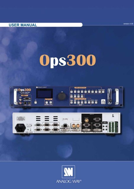
USER MANUAL<br />
Ops300<br />
version 4.00
THANK YOU<br />
Thank you for choosing <strong>Analog</strong> <strong>Way</strong>. By following these simple steps, you will be able to operate<br />
the powerful <strong>OPS300</strong>.<br />
TABLE OF CONTENTS<br />
INTRODUCTION<br />
HARDWARE INSTALLATION<br />
1-1. <strong>OPS300</strong> OPERATING MODES<br />
Mixer Mode<br />
Matrix Mode<br />
1-2. USEFUL TERMS AND DEFINITIONS<br />
2-1. SAFETY INSTRUCTION<br />
2-2. UNPACKING AND INSPECTION<br />
2-3. RACKMOUNT INFORMATION<br />
2-4. CABLE & ADAPTOR INFORMATION<br />
2-5. HARDWARE SPECIFICATIONS<br />
Input specifications<br />
Output specifications<br />
Communication specifications<br />
Environmental specifications<br />
Pin outs<br />
HDCP compliance<br />
CONNECTING THE <strong>OPS300</strong> 20<br />
3-1. CONNECTING THE <strong>OPS300</strong><br />
3-2. THE <strong>OPS300</strong> REAR PANEL<br />
Overview<br />
Inputs #1 to #8<br />
DVI Inputs #1 - #2<br />
SD/HD-SDI Inputs #1 - #2<br />
Preview Outputs<br />
Main Outputs<br />
1<br />
4<br />
4<br />
5<br />
6<br />
6<br />
11<br />
11<br />
11<br />
12<br />
20<br />
21<br />
1
2<br />
OPERATING THE <strong>OPS300</strong> 25<br />
4-1. THE <strong>OPS300</strong> FRONT PANEL 25<br />
Overview<br />
On/Off button<br />
Menu screen<br />
Menu scroll knob<br />
Control section<br />
Layer selection section<br />
Take button<br />
Input selection section<br />
Freeze button<br />
Audio-Video input 8<br />
T-Bar<br />
Effect selection button<br />
Preset selection button<br />
4-2. THE <strong>OPS300</strong> MENU<br />
Menu navigation<br />
Home menu<br />
4-3. WORKING WITH THE <strong>OPS300</strong><br />
Operating modes<br />
Reseting default values<br />
<strong>OPS300</strong> color codes<br />
• A- Settings in Mixer Mode<br />
• B- Settings in Native Matrix Mode<br />
Source input selection<br />
Input selection settings<br />
Source output selection<br />
Output selection settings<br />
Working with Layers<br />
Working with Native Matirx Mode<br />
Working with Cut, Fade or Transitions<br />
Capturing still frames<br />
Working with frames<br />
Capturing logos<br />
Memorizing logos<br />
Working with logos<br />
Layer transitions & effects<br />
Creating presets<br />
Working with presets<br />
Working with audio<br />
Working with preset layouts<br />
Audio configuration<br />
HOME MENU 53<br />
REMOTE CONTROL SOFTWARE 61<br />
5-1. THE <strong>OPS300</strong> RCS<br />
RCS presentation<br />
How to use the RCS<br />
Software installation<br />
Software overview<br />
Serial connection<br />
Ethernet connection<br />
28<br />
29<br />
61
5-2. WORKING WITH THE RCS<br />
Operating Mode<br />
Source input configuration<br />
Source output configuration<br />
Working with PIPs<br />
PIP Configuration<br />
Working with Frames<br />
Memorizing Frames<br />
Working with Logos<br />
Memorizing Logos<br />
Layer transitions & effects<br />
Creating Presets<br />
Working with Presets<br />
Working with Audio<br />
Audio configuration<br />
OPTIONAL REMOTE CONTROL SYSTEMS 70<br />
EXAMPLES AND TIPS<br />
6-1. Axion2 - Ref. ARC200<br />
6-2. Orchestra - Ref. ORC50<br />
6-3. TRK-800 - Ref. TRK-800<br />
6-4. RK-300 - Ref. RK-300<br />
7-1. ABOUT EXAMPLES<br />
7-2. EXAMPLES<br />
7-3. EXTERNAL PROGRAMMING<br />
WARRANTY AND SERVICES INFORMATION<br />
8-1. ANALOG WAY LIMITED WARRANTY<br />
8-2. SERVICES AND RMA<br />
CONTACT INFORMATION 76<br />
HOW TO CONTACT US<br />
INFORMATION ON DISPOSAL<br />
64<br />
70<br />
71<br />
72<br />
72<br />
72<br />
74<br />
75<br />
75<br />
75<br />
76<br />
76<br />
3
4<br />
INTRODUCTION<br />
1-1. THE <strong>OPS300</strong> OPERATING MODES<br />
Before you start setting up your <strong>OPS300</strong> for the first time, be sure you know what you actually want to do with<br />
it. The <strong>OPS300</strong> offers a choice of two operating modes, which results in a versatile video production tool for<br />
live event staging and fixed installation applications.<br />
* NOTE * : We recommend resetting the device to its default values every time you set up your shows or<br />
events (see the “Operating The <strong>OPS300</strong>” chapter, p25).<br />
MIXER MODE<br />
This mode allows for a single <strong>OPS300</strong> to seamlessly switch and blend any of its 12 analog/digital inputs with<br />
any other of the inputs, add PIP, titling or logo insertion to the live frame, while previewing your every move<br />
before going live, to avoid embarrassing errors on your main screen. The Mixer mode is the <strong>OPS300</strong> native<br />
mode, and with no less than 6 layers (of which 3 live layers). The <strong>OPS300</strong> with the Video output allows to<br />
have a full Main screen for recording or broadcasting.<br />
MATRIX MODE<br />
This mode turns your <strong>OPS300</strong> into a true 12x2 scaled matrix, while preserving seamless switching capabilities.<br />
Output #1 and #2 can be set to different resolutions and rates. Switching between any of the inputs can be<br />
done with the various effects (Cut, Fade, Slides…) and synchronized on both outputs.<br />
* NOTE * This mode leads the following restrictions: no PIPs, no logos and no frames.
1-2. USEFUL TERMS AND DEFINITIONS<br />
BACKGROUND: a Background is a source, typically originating from a computer. <strong>OPS300</strong> enables you to<br />
work with live or still (frame) background sources - visually in back of all other sources.<br />
LAYER: a Layer is an image display element (such as a PIP window, Key, Logo(s) or Background) that has<br />
an associated visual priority — either in front (or in back) of another layer.<br />
The <strong>OPS300</strong> can simultaneously view no less than 6 layers (3 video or live layers,<br />
1 frame layer or background and 2 logo layers).<br />
<strong>OPS300</strong> can insert up to 2 PIPs on a live background, plus 2 logos.<br />
LOGO2<br />
LOGO1<br />
PIP2<br />
PIP1<br />
Background Live<br />
Background Frame<br />
LAYER HIERARCHY<br />
PIP: a PIP (Picture In Picture), is a picture, typically of reduced size, which is positioned over another<br />
background image or PIP. PIPs can be reduced, enlarged and bordered. PIPs can overlap, depending on<br />
their visual priority.<br />
<strong>OPS300</strong> allows for Dynamic PIP on the opening and closing of the sequence, vertically or horizontally. A<br />
“flying” PIP is also possible over the screen with vertical, horizontal or diagonal animation. A PIP is considered<br />
as a live layer.<br />
FRAME: a Frame is a full screen image which is selected from one of the eight still frames which you can<br />
capture with the <strong>OPS300</strong>. A Frame can be flash captured from any video or computer source plugged into<br />
the machine (8 max).<br />
LOGO: a Logo is a partiel screen image that can be flash captured from any Video or Computer source, by<br />
keying or image cut-out. <strong>OPS300</strong> can record up to 8 still logos. They can be positioned anywhere on the<br />
screen. An animated logo is also available on the eighth input.<br />
KEYING: a Key is an electronic process whereby an image is electronically superimposed over another<br />
source or background, by cutting out either a color (Chroma Key), or its brightness or luminance levels (Luma<br />
Key). Keys are typically used for titles, logos and special effects. <strong>OPS300</strong> allows to use a live source with<br />
green or blue background and to key it over any other live input.<br />
5
6<br />
HARDWARE INSTALLATION<br />
2-1. SAFETY INSTRUCTION<br />
CAUTION:<br />
All of the safety and operating instructions should be read before the product is operated and should be<br />
maintained for further reference. Please follow all the warnings regarding this product and its operating<br />
instructions.<br />
• WARNING: To prevent the risk of electric shock and fire, do not expose this device to rain, humidity,<br />
intense heat sources (such as heaters and direct sunlight). Slots and openings in the device are provided<br />
for ventilation and to avoid overheating. Make sure the device is never placed near a textile surface that<br />
could block the openings. Also keep away from excessive dust, vibrations and shocks.<br />
• POWER: Only use the power supply indicated on the device of the power source. Devices equipped with<br />
a grounding plug should only be used with a grounding type outlet. In no way should this grounding be<br />
modified, avoided or suppressed.<br />
• POWER CORD: The device is equipped with a main switch (On (I) /Off (O)). The Switch ON and OFF is<br />
initiated by the main switch.<br />
Caution: The power cord is the only way to totaly disconnect the equipment from the main power.<br />
Apply the following guidelines:<br />
- The equipment connected to the network must have a release system easily<br />
accessible and located outside the unit.<br />
- Unplug the power cord, do not pull on the power cord but always on the plug itself.<br />
- The outlet should always be near the device and easily accessible.<br />
- Power supply cords should be routed so that they are not likely to be walked on or<br />
pinched by items placed upon or against them.<br />
If the power supply cord is damaged, unplug the device. Using the device with a damaged power supply cord<br />
may expose your device to electric shocks or other hazards. Verify the condition of the power supply cords<br />
once in a while. Contact your dealer or service center for replacement if damaged.<br />
• CONNECTIONS: All inputs and outputs (except for the power input) are TBTS defined under EN60950.<br />
• SERVICING: Do not attempt to service this product yourself by opening or removing covers and screws<br />
since it may expose your device to electric shocks or other hazards. Refer all problems to qualified<br />
service personnel.<br />
• OPENINGS: Never push objects of any kind into this product through the openings. If liquids have been<br />
spilled or objects have fallen into the device, unplug it immediately and have it checked by a qualified<br />
technician.
INSTRUCTIONS DE SECURITE<br />
Afin de mieux comprendre le fonctionnement de cet appareil nous vous conseillons de bien lire toutes les<br />
consignes de sécurité et de fonctionnement de l’appareil avant utilisation. Conservez les instructions de<br />
sécurité et de fonctionnement afin de pouvoir les consulter ultérieurement. Respectez toutes les consignes<br />
marquées dans la documentation, sur le produit et sur ce document.<br />
• ATTENTION: Afin de prévenir tout risque de choc électrique et d’incendie, ne pas exposer cet appareil à<br />
la pluie, à l’humidité et aux sources de chaleur intense.<br />
• INSTALLATION: Veillez à assurer une circulation d’air suffisante pour éviter toute surchauffe à l’intérieur<br />
de l’appareil. Ne placez pas l’appareil sur ou à proximité d’une surface textile susceptible d’obstruer<br />
les orifices de ventilation. N’installez pas l’appareil à proximité de sources de chaleur comme un<br />
radiateur ou une poche d’air chaud, ni dans un endroit exposé au rayonnement solaire direct, à des<br />
poussières excessives, à des vibrations ou à des chocs mécaniques. Ceci pourrait provoquer un mauvais<br />
fonctionnement et un accident.<br />
• ALIMENTATION: Ne faire fonctionner l’appareil qu’avec la source d’alimentation indiquée sur l’appareil.<br />
Les appareils doivent être obligatoirement connectés sur une source équipée d’une mise à la terre efficace.<br />
En aucun cas cette liaison de terre ne devra être modifiée, contournée ou supprimée.<br />
• CORDON D’ALIMENTATION: Les appareils sont équipés d’un interrupteur général (Marche I / Arrêt O),<br />
la mise en tension et la mise hors tension se fait en actionnant cet interrupteur général.<br />
Attention : le cordon d’alimentation constitue le seul moyen de débrancher l’appareil totalement de<br />
l’alimentation secteur. Pour être certain que l’appareil n’est plus alimenté, ce cordon doit être débranché<br />
de la prise murale.<br />
Appliquer les consignes suivantes:<br />
- Le matériel relié à demeure au réseau, doit avoir un dispositif de sectionnement facilement accessible<br />
qui doit être incorporé à l’extérieur de l’appareil.<br />
- Débrancher le cordon d’alimentation de la prise murale si vous prévoyez de ne pas utiliser l’appareil<br />
pendant quelques jours ou plus.<br />
- Pour débrancher le cordon, tirez-le par la fiche. Ne tirez jamais sur le cordon proprement dit.<br />
- La prise d’alimentation doit se trouver à proximité de l’appareil et être aisément accessible.<br />
- Ne laissez pas tomber le cordon d’alimentation et ne posez pas d’objets lourds dessus.<br />
Si le cordon d’alimentation est endommagé, débranchez-le immédiatement de la prise murale. Il est<br />
dangereux de faire fonctionner un appareil avec un cordon endommagé; un câble abîmé peut provoquer un<br />
risque d’incendie ou un choc électrique. Vérifiez le câble d’alimentation de temps en temps. Contactez votre<br />
revendeur ou le service après-vente pour un remplacement.<br />
• CONNEXIONS: Toutes les entrées et sorties (exceptée l’entrée secteur) sont de type TBTS (Très Basse<br />
Tension de Sécurité) définies selon EN 60950.<br />
• RÉPARATION ET MAINTENANCE: L’utilisateur ne doit en aucun cas essayer de procéder aux opérations<br />
de dépannage, car l’ouverture des appareils par retrait des capots ou de toutes autres pièces constituant<br />
les boîtiers ainsi que le dévissage des vis apparentes à l’extérieur, risquent d’exposer l’utilisateur à des<br />
chocs électriques ou autres dangers. Contactez le service après-vente, votre revendeur ou s’adresser à<br />
un personnel qualifié uniquement.<br />
• OUVERTURES ET ORIFICES: Les appareils peuvent comporter des ouvertures (aération, fentes, etc...),<br />
veuillez ne jamais y introduire d’objets et ne jamais obstruer ses ouvertures. Si un liquide ou un objet<br />
pénètre à l’intérieur de l’appareil, débranchez immédiatement l’appareil et faites-le contrôler par un<br />
personnel qualifié avant de le remettre en service.<br />
7
8<br />
INSTRUZIONI DI SECUREZZA<br />
Allo scopo di capire meglio il funzionamento di questa apparecchiatura vi consigliamo di leggere bene<br />
tutti i consigli di sicurezza e di funzionamento prima dell’utilizzo. Conservare le istruzioni di sicurezza e di<br />
funzionamento al fine di poterle consultare ulteriormente. Seguire tutti i consigli indicati su questo manuale<br />
e sull’apparecchiatura.<br />
• ATTENZIONE: Al fine di prevenire qualsiasi rischio di shock elettrico e d’incendio, non esporre<br />
l’apparecchiatura a pioggia, umidità e a sorgenti di eccessivo calore.<br />
• INSTALLAZIONE: Assicuratevi che vi sia una sufficiente circolazione d’aria per evitare qualsiasi<br />
surriscaldamento all’interno dell’apparecchiatura. Non collocare l’apparecchiatura in prossimità o su<br />
superfici tessili suscettibili di ostruire il funzionamento della ventilazione. Non installate l’apparecchiatura<br />
in prossimità di sorgenti di calore come un radiatore o una fuoruscita d’aria calda, né in un posto esposto<br />
direttamente ai raggi del sole, a polvere eccessiva, a vibrazioni o a shock meccanici. Ció potrebbe<br />
provocare un erroneo funzionamento e un incidente.<br />
• ALIMENTAZIONE: Far funzionare l’apparecchiatura solo con la sorgente d’alimentazione indicata<br />
sull’apparecchiatura. Le apparecchiature queste devono essere obbligatoriamente collegate su una<br />
sorgente fornita di una efficiente messa a terra. In nessun caso questo collegamento potrà essere<br />
modificato, sostituito o eliminato.<br />
• CAVO DI ALIMENTAZIONE: Gli apparecchi con un interrutore (commutatore) generale<br />
(Accesso I : Speuto 0), accendere ou spagnere l’apparecchio si fa usando l’interrutore.<br />
Attenzione: il cavo di alimentazione è il solo modo di disconnettere l’apparecchio dell’alimentazione. Per<br />
assicurarsi che totalemente l’apparecchio non è più collegato, il cavo deve essere disconesso della presa<br />
murale.<br />
Seguire le instruzioni seguenti:<br />
- Il materiale collegato a residenza alla rete, deve avere un dispositivo di sezionamento facile da<br />
raggiongere eche deve essere inserito all’esterno del apparecchio.<br />
- Disconnettere l’apparecchiatura dalla presa murale se si prevede di non utilizzarla per qualche giorno.<br />
- Per disconnettere il cavo tirare facendo forza sul connettore.<br />
- La presa d’alimentazione deve trovarsi in prossimità dell’apparecchiatura ed essere facilmente<br />
accessibile.<br />
- Non far cadere il cavo di alimentazione né appoggiarci sopra degli oggetti pesanti.<br />
Se il cavo di alimentazione é danneggiato, spegnere immediatamente l’apparecchiatura.<br />
E’ pericoloso far funzionare questa apparecchiatura con un cavo di alimentazione danneggiato, un cavo<br />
graffiato puó provocare un rischio di incendio o uno shock elettrico. Verificare il cavo di alimentazione<br />
spesso. Contattare il vostro rivenditore o il servizio assistenza per una sostituzione.<br />
• CONNESSIONE: Tutti gli ingressi e le uscite (eccetto l’alimentazione) sono di tipo TBTS definite secondo<br />
EN 60950.<br />
• RIPARAZIONI E ASSISTENZA: L’utilizzatore non deve in nessun caso cercare di riparare l’apparecchiatura,<br />
poiché con l’apertura del coperchio metallico o di qualsiasi altro pezzo costituente la scatola metallica,<br />
nonché svitare le viti che appaiono esteriormente, poiché ció puó provocare all’utilizzatore un rischio di<br />
shock elettrico o altri rischi.<br />
• APERTURE DI VENTILAZIONE: Le apparecchiature possono comportare delle aperture di ventilazione,<br />
si prega di non introdurre mai oggetti o ostruire le sue fessure. Se un liquido o un oggetto penetra<br />
all’interno dell’apparecchiatura, disconnetterla e farla controllare da personale qualificato prima di<br />
rimetterla in servizio.
SICHERHEITSHINWEISE<br />
Um den Betrieb dieses Geräts zu verstehen, raten wir Ihnen vor der Inbetriebnahme alle Sicherheits<br />
und Betriebsanweisungen genau zu lesen. Diese Sicherheits- und Betriebsanweisungen für einen<br />
späteren Gebrauch sicher aufbewahren. Alle in den Unterlagen, an dem Gerät und hier angegebenen<br />
Sicherheitsanweisungen einhalten.<br />
• ACHTUNG: um jegliches Risiko eines Stromschlags oder Feuers zu vermeiden, das Gerät nicht Regen,<br />
Feuchtigkeit oder intensiven Wärmequellen aussetzen.<br />
• EINBAU: Eine ausreichende Luftzufuhr sicherstellen, um jegliche Überhitzung im Gerät zu vermeiden.<br />
Das Gerät nicht auf und in Nähe von Textiloberflächen, die Belüftungsöffnungen verschließen können,<br />
aufstellen. Das Gerät nicht in Nähe von Wärmequellen, wie z.B. Heizkörper oder Warmluftkappe,<br />
aufstellen und es nicht dem direkten Sonnenlicht, übermäßigem Staub, Vibrationen oder mechanischen<br />
Stößen aussetzen. Dies kann zu Betriebsstörungen und Unfällen führen.<br />
• STROMVERSORGUNG: Das Gerät nur mit der auf dem Gerät bezeichnete Stromquelle betreiben. Gerät<br />
mit geerdeter Hauptstromversorgung muss an eine Stromquelle mit effizienter Erdung angeschlossen<br />
werden. Diese Erdung darf auf keinen Fall geändert, umgangen oder entfernt werden.<br />
• NETZKABEL: Da die Geräte über einen Hauptschalter (An I/ Aus 0) verfügen, erfolgt die Stromversorgung<br />
und -unterbrechung über diesen Hauptschalter.<br />
Achtung: Das Netzkabel stellt die einzige Möglichkeit dar, das Gerät vollständig vom Netzanschluss<br />
zu trennen. Um sicherzustellen, dass das Gerät nicht mehr versorgt wird, muss dieses Kabel aus der<br />
Netzsteckdose ausgesteckt werden.<br />
Bitte beachten Sie die folgenden Hinweise:<br />
- Wenn Geräte dauerhaft am Netz bleiben, müssen sie über eine leicht zugängliche Trennvorrichtung<br />
verfügen, die außen am Gerät angebracht sein muss.<br />
- Das Kabel mittels dem Stecker herausziehen. Niemals am Stromkabel selbst ziehen.<br />
- Die Steckdose muß sich in der Nähe des Geräts befinden und leicht zugänglich sein.<br />
- Das Stromkabel nicht fallen lassen und keine schweren Gegenstände auf es stellen.<br />
Wenn das Stromkabel beschädigt ist, das Gerät sofort abschalten. Es ist gefährlich das Gerät mit einem<br />
beschädigten Stromkabel zu betreiben; ein abgenutztes Kabel kann zu einem Feuer oder Stromschlag<br />
führen. Das Stromkabel regelmäßig untersuchen. Für den Ersatz, wenden Sie sich an Ihren Verkäufer<br />
oder Kundendienststelle.<br />
• ANSCHLÜSSE: Bei allen Ein- und Ausgängen (außer der Stromversorgung) handelt es sich, gemäß EN<br />
60950, um Sicherheits Kleinspannunganschlüsse.<br />
• REPARATUR UND WARTUNG: Der Benutzer darf keinesfalls versuchen das Gerät selbst zu reparieren,<br />
die Öffnung des Geräts durch Abnahme der Abdeckhaube oder jeglichen anderen Teils des Gehäuses<br />
sowie die Entfernung von außen sichtbaren Schrauben zu Stromschlägen oder anderen Gefahren für den<br />
Benutzer führen kann. Wenden Sie sich an Ihren Verkäufer, Ihre Kundendienststelle oder an qualifizierte<br />
Fachkräfte.<br />
• ÖFFNUNGEN UND MUNDUNGEN: Die Geräte können über Öffnungen verfügen (Belüftung, Schlitze,<br />
usw.). Niemals Gegenstände in die Öffnungen einführen oder die Öffnungen verschließen. Wenn eine<br />
Flüssigkeit oder ein Gegenstand in das Gerät gelangt, den Stecker herausziehen und es vor einer neuen<br />
Inbetriebnahme von qualifiziertem Fachpersonal überprüfen lassen.<br />
9
10<br />
INSTRUCCIONES DE SEGURIDAD<br />
Para comprender mejor el funcionamiento de este aparato, le recomendamos que le acuidadosamente todas<br />
las consignas de seguridad y de funcionamiento del aparato antes de usarlo. Conserve las instrucciones de<br />
seguridad y de funcionamiento para que pueda consultarlas posteriormente. Respete todas las consignas<br />
indicadas en la documentación, relacionadas con el producto y este documento.<br />
• CUIDADO: Para prevenir cualquier riesgo de choque eléctrico y de incendio, no exponga este aparato a<br />
la lluvia, a la humedad ni a fuentes de calorintensas.<br />
• INSTALACIÓN: Cerciórese de que haya una circulación de aire suficiente para evitar cualquier<br />
sobrecalentamiento al interior del aparato. No coloque el aparato cerca ni sobre una superficie textil que<br />
pudiera obstruir los orificios de ventilación. No instale el aparato cerca de fuentes de calor como radiador<br />
o boca de aire caliente, ni en un lugar expuesto a los rayos solares directos o al polvo excesivo, a las<br />
vibraciones o a los choques mecánicos. Esto podría provocar su mal funcionamiento o un accidente.<br />
• ALIMENTACIÓN: Ponga a funcionar el aparato únicamente con la fuente de alimentación que se indica<br />
en el aparato. Los aparatos deben estar conectados obligatoriamente a una fuente equipada con una<br />
puesta a tierra eficaz. Por ningún motivo este enlace de tierra deberá ser modificado, cambiado o<br />
suprimido.<br />
• CABLE DE ALIMENTACIÓN: Los equipos incluyan interruptor general de alimentación (Encender I /<br />
Apagar 0), la puesta en marcha o desconexión se realiza por medio de este interruptor.<br />
El cable de alimentación constituye el único medio de desconectar el aparato totalmente de la red eléctrica.<br />
Para estar seguro de que el aparato no está más alimentado, este cable debe de ser desconectado de la<br />
toma de corriente.<br />
Aplicar las siguientes consignas:<br />
- El material conectado a residencia a la red informática, debe de tener un dispositivo de seccionamiento<br />
fácilmente accesible que debe de ser incorporado al exterior del aparato.<br />
- Desconectar el aparato del enchufe mural si no piensa utilizarlo durante varios días.<br />
- Para desconectar el cable, tire de la clavija. No tire nunca del cable propiamente dicho.<br />
- El enchufe de alimentación debe estar cerca del aparato y ser de fácil acceso.<br />
- No deje caer el cable de alimentación ni coloque objetos pesados encima de él.<br />
Si el cable de alimentación sufriera algún daño, ponga el aparato inmediatamente fuera de tensión. Es peligroso<br />
hacer funcionar este aparato con un cable averiado, ya que un cable dañado puede provocar un incendio o un<br />
choque eléctrico. Verifique el estado del cable de alimentación de vez en cuando. Póngase en contacto con<br />
su distribuidor o con el servicio de posventa si necesita cambiarlo.<br />
• CONEXIONES: Todas las entradas y salidas (excepto la entrada del sector) son de tipo TBTS (Muy Baja<br />
Tensión de Seguridad) definidas según EN 60950<br />
• REPARACIÓN Y MANTENIMIENTO: Por ningún motivo, el usuario deberá tratar de efectuar operaciones<br />
de reparación, ya que si abre los aparatos retirando el capó o cualquier otra pieza que forma parte de<br />
las cajas o si destornilla los tornillos aparentes exteriores, existe el riesgo de producirse una explosión,<br />
choques eléctricos o cualquier otro incidente. Contacte el servicio de posventa, a su distribuidor o dirigirse<br />
con personal cualificado únicamente.<br />
• ABERTURAS Y ORIFICIOS: Los aparatos pueden contener aberturas (aireación, ranuras, etc.). No<br />
introduzca allí ningún objeto ni obstruya nunca estas aberturas. Si un líquido o un objeto penetra al<br />
interior del aparato, desconéctelo y hágalo revisar por personal cualificado antes de ponerlo nuevamente<br />
en servicio.
2-2. UNPACKING AND INSPECTION<br />
1 x <strong>OPS300</strong><br />
1 x Power supply cord<br />
2 x DVI male to HD15 female and DVI female cable<br />
1 x HD15 to 5 BNC cable<br />
1 x Ethernet cross cable (for device update)<br />
1 x DB9 to 4 BNC cable + mini-Din 4 (video out)<br />
1 x Set of 3 audio 10 pin screw terminals<br />
1 x RCS - Remote Control Software *<br />
1 x <strong>User</strong> <strong>Manual</strong> (<strong>PDF</strong> version) *<br />
1 x Quick Start Guide (<strong>PDF</strong> version) *<br />
* Download on our website: www.analogway.com<br />
2-3. RACKMOUNT INFORMATION<br />
Tabletop mounting: The <strong>OPS300</strong> can be used directly on a table, the unit is equipped with 4 handy anti-slip<br />
rubber feet.<br />
Rack mounting: The <strong>OPS300</strong> is compatible with a 19” enclosure. Please follow the instructions below to<br />
install the device in a 19” rack.<br />
Place the device in your rack. Attach the device to the rack by using 4 screws through the front panel holes<br />
(screws not included).<br />
Rear fixing is also recommended, in particular for permanent installations. The <strong>OPS300</strong> is equipped with drill<br />
holes designed for compatibility with most rackmount braces.<br />
Connect all of the cables of the device and attach them to the rack with the help of tie wraps.<br />
IMPORTANT:<br />
- The openings in the side and rear panels of the device are for cooling. Do not cover these openings to<br />
avoid cutting air circulation.<br />
- Be sure that no weight in excess of 2 kg (4.4 Lbs.) is added onto the <strong>OPS300</strong>.<br />
- The maximum ambient operating temperature should not exceed 40°C (104°F).<br />
- The rack and all mounted equipment in it must be reliably grounded according to national and/or local<br />
electrical standards.<br />
!<br />
Dismantling front handles of the device could invalidate warranty on after sales services of your<br />
<strong>OPS300</strong>. It is strongly advised to avoid using front handles as rests for your <strong>OPS300</strong>, they are<br />
designed for manipulation purposes only.<br />
If required, front handles of the device can be dismantled, but with caution.The original screws removed<br />
must not be reintroduced to their location without handles in place. Substancial damages can occur,<br />
including risk of electric shock from the main voltage. Only M4x12mm screws can be used. They are<br />
supplied with the unit.<br />
2-4. CABLE AND ADAPTOR INFORMATION<br />
WARNING !<br />
If required, front handles of the device can be dismantled,<br />
but with caution.<br />
The original screws removed must not be reintroduced to<br />
their location without handles in place.<br />
Substantial damages can occur, including risk of electric<br />
shock from the mains voltage.<br />
Only M4x12mm screws can be used.<br />
(They are supplied with the unit)<br />
A large choice of cables and adaptors are compatible with the <strong>OPS300</strong>. To find which are to be used in<br />
your setup, please refer to the Hardware Specifications chapter. Please contact your distributor for a list of<br />
available cables and connectors for your <strong>OPS300</strong>.<br />
11
12<br />
2-5. HARDWARE SPECIFICATIONS<br />
Input specifications<br />
• ANALOG COMPUTER:<br />
Connectors: Inputs #1 to #5: female HD15.<br />
Inputs #6 & #7: female DVI-I (analog pins).<br />
Input #8: female HD15.<br />
Line frequency: Up to 130 kHz (165 MHz Max pixel rate).<br />
Resolution: Up to 1600x1200 @ 165Mhz, 1920x1200px<br />
(RB, Max V size: 1200px, Max H size 2048px).<br />
Sync. types: RGBHV, RGB/S, RGsB (Sync On Green).<br />
Levels: R, G, B = 0.7 Vp/p.<br />
H & V Sync = TTL<br />
Composite Sync = TTL and 0.3 V (negative).<br />
SOG (Sync On Green) = 0.3 V.<br />
Impedance: R, G, B = 75 ohms.<br />
H = 75 ohms or Hi-Z.<br />
V = Hi-Z.<br />
• RGB/S - RGsB VIDEO:<br />
Connectors: Inputs #1 to #5: female HD15.<br />
Inputs #6 & #7: female DVI-I (analog pins).<br />
Input #8: female HD15.<br />
Frequency: 15.625 kHz - 50 Hz (625 lines).<br />
15.734 kHz - 60 Hz (525 lines).<br />
Levels: R, G, B = 0.7 Vp/p.<br />
SYNC. = 0.3 Vp/p or TTL (negative).<br />
Impedance: RGB = 75 ohms.<br />
SYNC. = 75 ohms or Hi-Z.<br />
• COMPONENT:<br />
Connectors: Inputs #1 to #5: female HD15.<br />
Inputs #6 & #7: female DVI-I (analog pins).<br />
Input #8: female HD15.<br />
Frequency: 15.625 kHz - 50 Hz (625 lines).<br />
15.734 kHz - 60 Hz (525 lines).<br />
Levels: Y = 1 Vp/p (0.7 V Luma + 0.3 V Sync.).<br />
Cr / Pr & Cb / Pb = 0.7 Vp/p.<br />
Impedance: 75 ohms.<br />
• HDTV - HD-YUV:<br />
Connectors : Inputs #1 to #5: female HD15.<br />
Inputs #6 & #7: female DVI-I (analog pins).<br />
Input #8: female HD15.<br />
Formats : 720p/576p (60Hz), 1080i (50/60Hz), EDTV.<br />
Levels : Y = 1 Vp/p (0.7 V + sync.).<br />
Cr / Pr & Cb / Pb = 1 Vp/p (0.7 V + sync.).<br />
Sync. : Tri-level: ±0.3V (positive/negative).<br />
Bi-level: 0.3V (negative).<br />
Impedance: 75 ohms.<br />
or
• S.VIDEO:<br />
Connectors: Inputs #1 to #5: female HD15.<br />
Inputs #6 & #7: female DVI-I (analog pins).<br />
Input #8: female HD15 + 4-pin MiniDin.<br />
Standard: PAL/SECAM: 15.625 kHz - 50Hz - 625 lines.<br />
NTSC (3.58 - 4.43 MHz): 15.734 kHz/60Hz/525 lines.<br />
Levels: Y = 1 Vp/p (0.7 V Luma + 0.3 V Sync.).<br />
C = 0.3 Vp/p (Chroma Burst).<br />
Impedance: 75 ohms.<br />
• COMPOSITE VIDEO:<br />
Connectors: Inputs #1 to #5: female HD15.<br />
Inputs #6 & #7: female DVI-I (analog pins).<br />
Input #8: female HD15 + RCA.<br />
Standard: PAL / SECAM: 15.625 kHz - 50 Hz - 625 lines.<br />
NTSC (3.58 - 4.43 MHz): 15.734 kHz - 60 Hz - 525 lines.<br />
Level: 1 Vp/p (0.7 V Luma + 0.3 V Sync.).<br />
Impedance: 75 ohms.<br />
• DVI (Digital Video Interface):<br />
Connector: DVI Inputs #1 & #2: female DVI-I (digital pins).<br />
Line frequency: Up to 130 kHz (165 MHz Max pixel rate).<br />
Format: Digital Visual Interface (DVI)-TMDS single link.<br />
Resolution: Up to 1600x1200 @ 165Mhz, 1920x1200px<br />
(RB, Max V size: 1200px, Max H size 2048px).<br />
• SD-SDI:<br />
Connector: SDI Inputs #1 & #2: female BNC.<br />
Formats: SMPE 259M-C<br />
Data rate: 270 Mbps serial digital.<br />
Impedance: 75 ohms.<br />
• HD-SDI:<br />
Connector: SDI Inputs #1 to #2: female BNC.<br />
Formats: 720p @ 50, 59.94 & 60 Hz.<br />
1035i @ 50, 59.94 & 60 Hz.<br />
1080i @ 50, 59.94 & 60 Hz.<br />
1080p @ 23.97, 24, 25, 29.97, 30 & 60 Hz.<br />
1080sF @ 50, 59.94 & 60 Hz.<br />
Data rate: 1.54 Gbps serial digital - SMPTE 292M.<br />
2.97 Gbps serial digital - SMPTE 424M (3G-SDI).<br />
Impedance: 75 ohms.<br />
• AUDIO INPUT:<br />
Connectors: Balanced or unbalanced mono/stereo inputs<br />
(or 10-pin MCO male connector or 3,5mm Jack).<br />
Inputs #1 & #4: 3,5mm Jack Stereo Connector input<br />
(unbalanced connection).<br />
Inputs #5 to #6 and DVI #1 to DVI #2<br />
(or 10-pin MCO male connector) (Unbalanced connection).<br />
Input #5 LEFT<br />
RIGHT<br />
GROUND(S)<br />
Input #6 LEFT<br />
RIGHT<br />
DVI 1<br />
DVI 2<br />
LEFT<br />
RIGHT<br />
GROUND(S)<br />
LEFT<br />
RIGHT<br />
RIGHT (ring)<br />
GROUND<br />
LEFT (tip)<br />
3.5 mm JACK connector<br />
UNBALANCED<br />
5<br />
6<br />
DVI1<br />
DVI 2<br />
L<br />
R<br />
L<br />
R<br />
L<br />
R<br />
L<br />
R<br />
13
14<br />
Inputs #7 and AUX (or 10-pin MCO male connector)<br />
(Balanced connection).<br />
• ANALOG OUTPUTS<br />
Connector: Outputs #1 (Main) & #2 (Preview): female HD15, DVI-I (analog pins).<br />
Resolutions:<br />
Output specifications<br />
Format Ratio Available Refresh Rates Reduced Blanking<br />
640 x 480 4 : 3 50Hz 60Hz 72Hz 75Hz<br />
800 x 600 4 : 3 50Hz 60Hz 72Hz 75Hz<br />
848 x 480 16 : 9 50Hz 60Hz 72Hz 75Hz<br />
1024 x 768 4 : 3 50Hz 60Hz 72Hz 75Hz<br />
1280 x 720 16 : 9 50Hz 60Hz<br />
1280 x 768 15 : 9 50Hz 60Hz 72Hz 75Hz<br />
1280 x 800 16 : 10 50Hz 60Hz 72Hz 75Hz<br />
1280 x 1024 5 : 4 50Hz 60Hz 72Hz 75Hz<br />
1360 x 768 16 : 9 50Hz 60Hz 72Hz 75Hz<br />
1366 x 800 15 : 9 50Hz 60Hz 72Hz 75Hz<br />
1400 x 1050 4 : 3 50Hz 60Hz 72Hz 75Hz<br />
1440 x 900 16 : 10 50Hz 60Hz 72Hz 75Hz<br />
1600 x 1200 4 : 3 50Hz 60Hz<br />
1680 x 1050 16 : 10 50Hz 60Hz<br />
1920 x 1080 16 : 9 50Hz 60Hz 72Hz 75Hz YES<br />
1920 x 1080 B 16 : 9 50Hz 60Hz YES<br />
1920 x 1080 C 16 : 9 50Hz 60Hz YES<br />
1920 x 1080 HD 16 : 9 50Hz 60Hz YES<br />
1920 x 1200 16 : 10 50Hz 60Hz YES<br />
2048 x 1080 19 : 10 50Hz 60Hz YES<br />
Signals: RGBHV, RGBS and RGsB.<br />
Levels: R, G, B = 0.7 Vp/p.<br />
Sync.: Separate H & V = TTL (negative).<br />
Composite = TTL (negative).<br />
SOG = 0.3 Vp/p (negative).<br />
Impedance: R, G, B = 75 ohms.<br />
Input #5<br />
Input #6<br />
DVI 1<br />
DVI 2<br />
LEFT<br />
RIGHT<br />
GROUND(S)<br />
LEFT<br />
RIGHT<br />
LEFT<br />
RIGHT<br />
GROUND(S)<br />
LEFT<br />
RIGHT<br />
UNBALANCED<br />
5<br />
6<br />
DVI 1<br />
DVI 2<br />
L<br />
R<br />
L<br />
R<br />
L<br />
R<br />
L<br />
R
• DVI (Digital Video Interface) OUTPUTS<br />
Connector: Outputs #1 (Main) & #2 (Preview): female DVI-I (digital pins).<br />
Signal: Digital Visual Interface (DVI)-TMDS single link.<br />
Resolutions:<br />
Format Ratio Refresh Rate Reduced Blanking<br />
640 x 480 4 : 3 50Hz 60Hz 72Hz 75Hz<br />
800 x 600 4 : 3 50Hz 60Hz 72Hz 75Hz<br />
848 x 480 16 : 9 50Hz 60Hz 72Hz 75Hz<br />
1024 x 768 4 : 3 50Hz 60Hz 72Hz 75Hz<br />
1280 x 720 16 : 9 50Hz 60Hz<br />
1280 x 768 15 : 9 50Hz 60Hz 72Hz 75Hz<br />
1280 x 800 16 : 10 50Hz 60Hz 72Hz 75Hz<br />
1280 x 1024 5 : 4 50Hz 60Hz 72Hz 75Hz<br />
1360 x 768 16 : 9 50Hz 60Hz 72Hz 75Hz<br />
1366 x 800 15 : 9 50Hz 60Hz 72Hz 75Hz<br />
1400 x 1050 4 : 3 50Hz 60Hz 72Hz 75Hz<br />
1440 x 900 16 : 10 50Hz 60Hz 72Hz 75Hz<br />
1600 x 1200 4 : 3 50Hz 60Hz<br />
1680 x 1050 16 : 10 50Hz 60Hz<br />
1920 x 1080 16 : 9 50Hz 60Hz 72Hz 75Hz YES<br />
1920 x 1080 B 16 : 9 50Hz 60Hz YES<br />
1920 x 1080 C 16 : 9 50Hz 60Hz YES<br />
1920 x 1080 HD 16 : 9 50Hz 60Hz YES<br />
1920 x 1200 16 : 10 50Hz 60Hz YES<br />
2048 x 1080 19 : 10 50Hz 60Hz YES<br />
• AUDIO OUTPUT<br />
Connector: Output #1 (Main) and #2 (Prelist):<br />
2 Balanced or unbalanced mono/stereo<br />
outputs (on 10-pin MCO male connector).<br />
Vo max: Unbalanced = +15dBu (at 300Ω load).<br />
Balanced = +21dBu (at 600Ω load).<br />
Zo = 600Ω balanced.<br />
Zo = 300Ω unbalanced.<br />
G = 0 dB nominal.<br />
Outputs #1 to #2: Balanced & unbalanced connection<br />
4<br />
L+<br />
L-<br />
L+<br />
L-<br />
GROUND(S)<br />
R+<br />
R+<br />
R-<br />
R-<br />
L+<br />
L-<br />
L+<br />
L-<br />
GROUND(S)<br />
R+<br />
R+<br />
R-<br />
R-<br />
BALANCED<br />
15
16<br />
The video output generates a SDI signal in which is embedded only one stereo audio stream.<br />
• VIDEO OUT<br />
Settings Availability<br />
Gain Yes: from -∞ to +18dB<br />
Balanced Audio Left and Right<br />
Auxiliary Input Mixing Yes<br />
Adjusting Audio Delay Yes: from 0 to 80ms (Automatic or <strong>Manual</strong>)<br />
Connector: 1 x female BNC<br />
SD-SDI: Female BNC.<br />
Formats: SMPTE 259M-C.<br />
Data rate : 270 Mbps serial digital.<br />
Impedance: 75 ohms.<br />
HD-SDI: Female BNC.<br />
Formats: 720p @ 50, 59.94 & 60 Hz.<br />
1035i @ 59.94 & 60 Hz.<br />
1080i @ 50, 59.94 & 60 Hz.<br />
1080p @ 23.97, 24, 25, 29.97, 30 & 60 Hz.<br />
1080sF @ 50, 59.94 & 60 Hz.<br />
Data rate: 1.54 Gbps serial digital - SMPTE 292M.<br />
2.97 Gbps serial digital - SMPTE 424M (3G-SDI).<br />
Connector: 1 x female DB9<br />
(This connection must be used with the cable supplied in the packaging: DB9 to 4 BNC<br />
cable + mini-4Din).<br />
Formats: SDTV PAL & NTSC<br />
Signals: Component: Red, green and blue wires<br />
S-Video: Mini-4Din (white and black wires)<br />
Composite: Grey wire<br />
Impedence: 75 ohms<br />
Cable reference for spare part: #10120<br />
Communication specifications<br />
• COMMUNICATION PORTS<br />
REMOTE RS232<br />
Connector: DB 9 female.<br />
Protocol: RS-232.<br />
Data Rate: 9600 Bauds, 8 data bits, 1 stop bit, no parity bit, no flow control<br />
by default.<br />
DTR & RTS needed for upgrade.<br />
• LAN<br />
Connector: RJ45.<br />
Protocol: TCP (Transmission Control Protocol) or UDP<br />
(<strong>User</strong> Datagram Protocol).<br />
Ethernet: Base 10/100.
Environmental specifications<br />
Dimensions: W 482 x D 330 x H 88 mm<br />
19”W x 13”D x 3.50”H<br />
Weight: 5 kg / 11 lbs<br />
(Compatible with a Standard 19” rack, Height = 2 U)<br />
Cooling air flow from right side to left side.<br />
Max ambient operating temperature: < 40°C (< 104°F).<br />
Operating temperature: 0 to +40°C / +32°F to +104°F<br />
Storage temperature: -25 to +85°C / -13°F to +185°F<br />
Operating humidity: 10 to 80% (non condensing)<br />
Input voltage range: 100-240 VAC, 50/60 Hz<br />
Typical consumption: 90 W<br />
CE Compliancy, test following:<br />
- EN 55022: 2006 / A1: 2007,<br />
- EN 55024: 1998 / A1: 2001 / A2: 2003,<br />
- EN 61000-3-2: 2006,<br />
- EN 61000-3-3: 1995 / A1: 2001 / A2: 2005.<br />
Safety, test following:<br />
- IEC 60950-1: 2005,<br />
- UL 60950-1: 2007,<br />
- CAN/CSA-C22.2 NO. 60950-1.<br />
Power supply: IEC/EN/UL/CSA 60950-1, internal, autoswitching<br />
Mechanical (in carton): Vibration: IEC60068-2-64<br />
Free fall: IEC60068-2-32, RoHS, WEEE<br />
17
18<br />
Pinouts<br />
• VGA<br />
STANDARD VGA<br />
1- Red 6- Red Return 11- ID Bit 0<br />
2- Green 7- Green Return 12- ID Bit 1<br />
3- Blue 8- Blue Return 13- H Sync<br />
4- ID Bit 2 9- No Pin 14- V Sync<br />
5- Test (Gnd) 10- Sync Return 15- ID Bit 3<br />
• DIGITAL VISUAL INTERFACE DVI<br />
Pin<br />
1- TMDS Data 2- 7- DDC Data 13- Not used 19- TMDS Data 0 Shield<br />
2- TMDS Data 2+ 8- <strong>Analog</strong> Vertical Sync 14- +5V (Power) 20- Not used<br />
3- TMDS Data 2 Shield 9- TMDS Data 1- 15- Ground for (+5V) 21- Not used<br />
4- Not used 10- TMDS Data 1+ 16- Hot Plug Detect. 22- TMDS Clock Shield<br />
5- Not used 11- TMDS Data 1 Shield 17- TMDS Data 0- 23- TMDS Clock +<br />
6- DDC Clock 12- Not used 18- TMDS Data 0+ 24- TMDS Clock-<br />
C1- <strong>Analog</strong> Red Video (or Cr/Pr or C) C4- <strong>Analog</strong> Horizontal Sync (or Composite Sync)<br />
C2- <strong>Analog</strong> Green Video (or Y or Composite Video) C5- <strong>Analog</strong> Common Ground Return<br />
C3- <strong>Analog</strong> Blue Video (or Cb/Pb)<br />
DDC = Display Data Channel<br />
TMDS = Transition Minimized differential signal<br />
• RS-232 CONNECTOR<br />
Pin<br />
1- NC 6- NC<br />
2- Transmit data to PC (Tx1) 7- NC<br />
3- Transmit data from PC (Rx1) 8- NC (or +12V. dc)<br />
4- Receive data from display unit (Rx2) 9- Transmit data to display unit (Tx2)<br />
5- Ground<br />
• S-VIDEO (Y/C) CONNECTOR - 4-pin Mini Din<br />
Pin<br />
1- Y Ground 2- C Ground 3- Y Signal 4- C Signal<br />
• VESA DDC (Inputs #1, #2 and #8)<br />
Pin<br />
1- Red 6- Red Return 11- ID Bit<br />
2- Green 7- Green Return 12- Bi-directional data (SDA)<br />
3- Blue 8- Blue Return 13- H Sync<br />
4- ID Bit 2 0 9- DDC+5 Volt supply 14- V Sync<br />
5- Test 10- Sync Return 15- Data Clock (SCL)<br />
• Video Out (SD/HDTV) (Specific Wiring)<br />
Pin<br />
1<br />
Ground (red, green, blue, composite)<br />
2<br />
3 Red (R-Y)<br />
4 Green (Y)<br />
5 Blue (B-Y)<br />
6 Y (S.VIDEO)<br />
7 COMPOSITE VIDEO<br />
8 Ground (Y+C)<br />
9 C (S.VIDEO)
HDCP compliance<br />
If you want to use HDCP content from your sources, be sure pluging HDCP compliant screens or projectors.<br />
If it’s not the case, the output image could be disabled.<br />
When displaying HDCP protected sources on non HDCP compliant equipment, the following message will be<br />
displayed on the device VFD screen:<br />
“Due to HDCP content, non HDCP screens cannot display protected sources”<br />
Your screen will go to black without displaying the HDCP input image, or partially layer out non HDCP content.<br />
Concerning the DVI inputs, a specific feature allows enable/disable the HDCP receiver for the input chosen.<br />
It can be very useful especially when using a Mac:<br />
Input Menu > DVI# > HDCP detection<br />
The output status can provides you all information about the output in real time.<br />
This feature is particularly needed when HDCP is used with long cable to be sure that the communication is<br />
well handled.<br />
To summarize all HDCP status, please see in the Control Menu --> HDCP Summary.<br />
!<br />
NOTE: as part of our policy of continuous improvement, <strong>Analog</strong> <strong>Way</strong> reserves the right to make<br />
design and specification changes for product improvements without prior notice. The performance<br />
specification figures indicated are nominal values of production units. There may be some deviations<br />
from these values in individual units.<br />
19
20<br />
CONNECTING THE <strong>OPS300</strong><br />
3-1. CONNECTING THE <strong>OPS300</strong><br />
The <strong>OPS300</strong> can be set up with up to 12 different sources, and will drive up to 2 digital DVI-D sources, 2 SD-<br />
SDI sources and 8 analog computer/video sources simultaneously. The versatility of the <strong>OPS300</strong> will allow<br />
for almost any event configuration and cater for all your projection needs.<br />
The intuitive rear panel of the <strong>OPS300</strong> will let you set up for the first time quickly and easily. Here is an<br />
example of a typical <strong>OPS300</strong> setup.<br />
STAGE<br />
Sources<br />
ANNUAL SALES REPORT<br />
TITLE 1<br />
LIVE BACKGROUND<br />
Main out<br />
Computer<br />
(Live Background) Laptop<br />
HD-Cam<br />
(PIP 1)<br />
(Background Frame)<br />
PIP 2 PIP 1<br />
HD-Cam<br />
(PIP 2)<br />
Laptop<br />
(PIP 1)<br />
Preview out<br />
Laptop<br />
(PIP 2)<br />
Preview<br />
Monitor<br />
DVD/BluRay<br />
(Live Background)
3-2. THE <strong>OPS300</strong> REAR PANEL<br />
Overview<br />
The <strong>OPS300</strong> rear panel is equipped with 11 universal digital and analog inputs. Inputs #1 through #5 (3) are<br />
universal analog inputs. Inputs #6 & #7 share a DVI-D signal and a universal analog signal (plug the shipped<br />
<strong>Analog</strong> <strong>Way</strong> DVI/HD15 adaptor cable to use DVI-D and analog signals simultaneously).<br />
The Main and Preview (6) outputs will allow for the <strong>OPS300</strong> high resolution digital and analog signals to be<br />
viewed on screen and/or on a preview monitor (see also Output Specifications in this chapter).<br />
The extra Video Out card installed on the <strong>OPS300</strong>, can be used for recording, broadcasting or previewing<br />
purposes in a wide range of formats for maximum compatibility with industry viewing or recording equipment.<br />
Finally, the audio in and output card will let users trigger audio with any source, accurately balance or tweak<br />
sound sources and outputs.<br />
1 : AC outlet and ON/OFF switch<br />
2 : IP-LAN connector<br />
3 : Universal <strong>Analog</strong> inputs<br />
4 : DVI-I Input (DVI-D + <strong>Analog</strong>)<br />
5 : HD-SDI inputs<br />
6 : Main and Preview outputs<br />
7 : SD-HD/SDI output<br />
8 : SD/HDTV output<br />
9 : Audio inputs<br />
10 : Audio outputs<br />
11 : RS232 connector<br />
11 2 5 7 8<br />
1 3 4 6 9 10<br />
21
22<br />
Inputs #1 to #8<br />
UNIVERSAL COMPUTER & VIDEO INPUTS<br />
Universal Inputs accept computer sources (RGBHV, RGBS,<br />
and RGsB (SOG) signals), standard TV/VIDEO sources<br />
(Composite video, S.VIDEO), Component video (YUV, RGBS<br />
& RGsB (SOG)), and HDTV sources (480p, 720p & 1080i).<br />
HD15: 1 x Universal <strong>Analog</strong> input on female HD15 connector.<br />
COMPUTER SOURCES:<br />
The device accepts the following computer signals: RGBHV,<br />
RGB/S, and RGsB on inputs #1 to #8.<br />
COMPOSITE VIDEO SOURCES:<br />
The Composite Video signal, usually called COMPOSITE or<br />
VIDEO, is available on most video equipment (VCR, DVD,<br />
CAMCORDER…), but is also the lowest in picture quality.<br />
The video standard of this signal can be NTSC, PAL or<br />
SECAM. The signal is transmitted on a single coaxial cable,<br />
and is connected to the video equipment with an HD15<br />
connector.<br />
For inputs #1 to #5: connect a 1 x BNC from your composite<br />
source, to the HD15 input of the device.<br />
For input #8: connect 1 x BNC from your composite source,<br />
to the composite RCA input of the device.<br />
S.VIDEO SOURCES:<br />
The S.VIDEO signal, also called Y/C, HI-8, or S.VHS, is<br />
available on DVD players and high quality VCRs (S.VHS).<br />
The S.VIDEO signal in which the Luminance (Y) and<br />
Chrominance (C) information are separately transmitted,<br />
gives a higher quality picture than the Composite video<br />
signal. The S.VIDEO connector is usually a 4-pin Mini-DIN<br />
connector also called Oshiden connector.<br />
For inputs #1 to #5: connect a 2 x BNC from your S.VIDEO,<br />
Y (G/Y) & C (R/R-Y), to the HD15 input of the device.<br />
For input #8: connect a 2 x BNC from your S.VIDEO, Y (G/Y)<br />
& C (R/R-Y), to a 4-pin mini DIN cable, or to the HD15 input<br />
of the device.<br />
R<br />
G<br />
Composite Source<br />
R<br />
G B S<br />
RGBS Source<br />
<strong>Analog</strong> Computer Sources<br />
G<br />
S.Video Source
COMPONENT VIDEO SOURCES:<br />
The Component Video signal, also called YUV (Y, Pr, Pb)<br />
or BETACAM is widely used in broadcasting and is<br />
available on high-quality DVD players. The COMPONENT<br />
signal is transmitted with 3 coaxial cables, and also has<br />
a better quality picture than COMPOSITE and S.VIDEO<br />
signals. The COMPONENT connectors are usually RCA<br />
(x3), or BNC (x3).For inputs #5 to #8: connect a HD15 to<br />
3 x BNC cable between the HD15 connector of the device<br />
and your Component source.<br />
RGBS VIDEO SOURCES:<br />
This signal is widely used in broadcasting and is available<br />
on European DVD player. The RGB/S signal is transmitted<br />
with 4 coaxial cables, and also has a better picture quality<br />
than COMPOSITE and S.VIDEO signals. The RGB/S<br />
connectors are usually BNC connectors for Broadcasting<br />
equipment, and SCART connector for DVD players.<br />
For inputs #1 to #5 and #8: connect a HD15 to 4 x BNC<br />
cable between the HD15 connector of the device and your<br />
RGB/S source.<br />
DVI Inputs #1 - #2<br />
DVI AND ANALOG SOURCES:<br />
DVI Inputs #1- #2 on the <strong>OPS300</strong> accept up to 2 live sources<br />
in Digital format.<br />
DVI-I: 1 x digital (DVI) and 1 x analog input on<br />
female DVI-I universal connector.<br />
SD/HD-SDI Inputs #1 - #2<br />
SD/HD-SDI SOURCES:<br />
SD/HD-SDI Inputs #1- #2 on the <strong>OPS300</strong> accept up to 2 live<br />
sources in Digital formats.<br />
SD/HD-SDI: 1 x digital input on female BNC connector.<br />
Preview Outputs<br />
PREVIEW OUTPUT:<br />
ANALOG: 1 x analog output for the main display<br />
device on female HD15 connector.<br />
DIGITAL/ANALOG: 1 x main output on female DVI-I<br />
connector (simultaneous analog and<br />
digital).<br />
R<br />
R<br />
G B<br />
Component (YUV) Source<br />
G B S<br />
RGBS Source<br />
DVI-D<br />
Digital & <strong>Analog</strong> Computer Sources<br />
BNC<br />
HD/SDI Source<br />
23
24<br />
MAIN OUTPUT:<br />
ANALOG: 1x analog output for the main display device on female HD15<br />
connector.<br />
DIGITAL/ANALOG: 1x main output on female DVI-I connector<br />
(simultaneous analog and digital).<br />
VIDEO OUTPUT:<br />
Video Output card provides SD or HDTV formats in various signals and<br />
connectors from Composite Video to HD SDI. This output can be used to<br />
record your show by outputting the same content as the Main output in Mixer<br />
Mode, or a choice between output #1 or #2 in Matrix Mode (see also <strong>OPS300</strong><br />
Modes, p.4).<br />
AUDIO SWITCHER:<br />
Main Outputs<br />
Audio Stereo Switcher card features 12 inputs and 2 outputs. An additional<br />
auxiliary input can be mixed with any other input. Master Volume and<br />
individual input level can be adjusted. Each input and output offers balanced<br />
or unbalanced connections. It should be noted that the management of the<br />
audio output follows the selection of video layers. Two modes are available:<br />
Top Follow or Breakaway. In Top Follow Mode, the audio follows the topmost<br />
video layer (after having pressed [TAKE]). In Breakaway Mode, it is the<br />
selected audio layer input that is permanently diffused.
OPERATING THE <strong>OPS300</strong><br />
4-1. THE <strong>OPS300</strong> FRONT PANEL<br />
Overview<br />
The highly intuitive front panel of the <strong>OPS300</strong> was designed by <strong>Analog</strong> <strong>Way</strong> engineers to simply and quickly<br />
meet all of your event needs. Within minutes, you will be able to enjoy its full potential and easily parameter<br />
most of its functions, without having to be an expert audio-visual engineer, leaving room for what is most<br />
important to our users: concentrating on their event.<br />
The <strong>OPS300</strong> front panel is comprised of several sections, each carefully labelled and self explanatory,<br />
corresponding to all the machine’s versatile functions.<br />
1 : Standby button<br />
2 : Menu screen<br />
3 : Menu scroll knob<br />
4 : Control section<br />
5 : Layer Selection section<br />
6 : Input Selection section<br />
7 : Freeze button<br />
8 : Audio-Video input 8<br />
9 : Take button<br />
10 : T-Bar<br />
11 : Effect selection button<br />
12 : Preset selection button<br />
8<br />
1<br />
2 3<br />
6 7<br />
4<br />
5<br />
11 12<br />
9<br />
10<br />
25
26<br />
On/Off button<br />
The [STANDBY] button allows users to put the <strong>OPS300</strong> into sleep<br />
mode, and startup again. The [STANDBY] button does not replace<br />
the ON/OFF switch at the rear of the unit, and is implemented<br />
essentially for ease-of-use in rackmount situations.<br />
--> Hold for 3 seconds for stand-by mode<br />
Menu screen<br />
The Menu Screen of the <strong>OPS300</strong> is the visual interface to your<br />
<strong>OPS300</strong> menu. It gives users a constant indication of available menu<br />
options, parameters of any selected object, system information, and<br />
everything you need to know to control the device.<br />
Menu scroll knob<br />
The Menu scroll knob allows users to quickly scroll through menu<br />
items and increase or decrease any modifiable value in the <strong>OPS300</strong><br />
menu. Simply scroll to the desired menu item, and press the [ENTER]<br />
button to confirm your choice.<br />
Control section<br />
The [EXIT/MENU] and the [ENTER] button in the Control section of<br />
the <strong>OPS300</strong>, allow users to respectively enter and exit the <strong>OPS300</strong><br />
menu, and confirm selected menu items.<br />
Layer selection section<br />
The Layer Selection section allows to select which type of layer to<br />
work with:<br />
• Background Frame (non-positionable, non-resizable static background),<br />
• Background Live (positionable, resizable animated background),<br />
• PIP (positionable, sizable floating window),<br />
• Logo (positionable, key sensitive layer).<br />
Take button<br />
The <strong>OPS300</strong> [TAKE] button allows to switch from Preview to Main<br />
outputs. By pressing the [TAKE] button, what you have setup on your<br />
preview screen will be transitioned to the Main output display.
Input selection section<br />
The Input Selection section allows to select<br />
which input (#1 to #12) to display in a selected<br />
layer. Select one of 12 simultaneous inputs, (8<br />
analog inputs, 2 DVI-D inputs, 2 SDI inputs) by<br />
simply pressing one of the Input buttons.<br />
The [BLACK] button allows users to remove layer content on screen.<br />
Freeze button<br />
The [FREEZE] button of the <strong>OPS300</strong> allows users to freeze the<br />
Main output current display or the active input, depending on the<br />
freeze mode: FREEZE ALL or freeze the current selected input<br />
INPUT FREEZE.<br />
Audio-Video input 8<br />
The handy front panel Audio-Video Input 8 lets users quickly access<br />
an extra universal analog input source, without the hastle of recabling<br />
the <strong>OPS300</strong> rear panel, or for quick source changes during<br />
a show or presentation.<br />
T-Bar<br />
The <strong>OPS300</strong> T-Bar allows to switch from Preview to Main outputs<br />
manually, and as gradually as you wish. By sliding the T-Bar, what<br />
you have setup on your preview screen will go live on the Main<br />
output display at the same speed as you slide it.<br />
Effect selection button<br />
The <strong>OPS300</strong> [EFFECT] selection button is the shortcut to the current<br />
layer.<br />
Preset selection button<br />
The <strong>OPS300</strong> [PRESET] selection button allows you to instantly<br />
recall a saved preset.<br />
27
28<br />
4-2. THE <strong>OPS300</strong> MENU<br />
Menu navigation<br />
To access the <strong>OPS300</strong> menu, press the [EXIT/MENU] button in the control section (4). To highlight items in<br />
the menu which will appear on the VFD screen (2), turn the scroll knob (3) left or right to the desired menu<br />
item. When you have reached the desired menu item, press the [ENTER] button in the control section (4) to<br />
access that menu function. Pressing the [ENTER] button when a selection has been made sets the value to<br />
that selection in the <strong>OPS300</strong> memory. When all settings have been made, press the [EXIT/MENU] button to<br />
exit sub-menus and return to the main menu.<br />
* IMPORTANT * : simply selecting a menu item will not set it to that value. Be sure to press the [ENTER]<br />
button when parametering the menu items.<br />
Home menu<br />
1<br />
2 3<br />
4<br />
Pressing the [MENU] button in the menu section of the <strong>OPS300</strong>, will display and give you access to the<br />
following items on the menu VFD screen:<br />
- MODE: select to choose which mode the <strong>OPS300</strong> will work (in Mixer or Matrix see <strong>OPS300</strong> Modes p.4).<br />
- INPUT: select to configure the 12 individual input types and resolutions.<br />
- MAIN OUT: in Mixer Mode, select to set the output types and resolutions of the Main output.<br />
- OUTPUT 1: in Matrix Mode, select to set the output types and resolutions of Output 1.<br />
- PREVIEW OUT: in Mixer Mode, select to set the output types and resolutions of the Preview output.<br />
- OUTPUT 2: in Matrix Mode, select to set the output types and resolutions of Output 2.<br />
- VIDEO OUT: select to configure Video output card settings.<br />
- PRESET: select to store and use presets.<br />
- IMAGE: select to change source image settings of an input.<br />
- KEYING/TITLING: select to access keying and titling controls and parameters when video layer is selected.<br />
- LAYER: select to adjust layer size, position, border, transparency or transitions.<br />
- LOGO/FRAME: select to store (record) and manage logos and frames into the <strong>OPS300</strong>.<br />
- AUDIO: select to access all audio input and output parameters.<br />
- CONTROL: select to access device software information, LAN settings, reset factory settings, amongst<br />
other user oriented functions.
4-3. WORKING WITH THE <strong>OPS300</strong><br />
Operating modes<br />
The <strong>OPS300</strong> offers 2 modes to work from: the Mixer Mode, which is the <strong>OPS300</strong> default mode and the Matrix<br />
Mode, which turns your <strong>OPS300</strong> into a true 12 x 2 scaled matrix with numerous effects.<br />
* NOTE * : the <strong>OPS300</strong> will only let you work on your preview screen (direct access to main screen is locked).<br />
In Matrix mode, the <strong>OPS300</strong> loses the use of layers, PIPs and logos.<br />
To choose which mode the <strong>OPS300</strong> will work in, press the [EXIT/MENU] button and select Mode in the menu<br />
by rotating the scroll knob. Then press the [ENTER] button to enter the Mode sub-menu. Select the desired<br />
mode by rotating the scroll knob, and press the [ENTER] button to confirm your choice. Press the [EXIT/<br />
MENU] button to return to the main menu.<br />
Reseting default values<br />
It is strongly recommended resetting all of the default values of your <strong>OPS300</strong> unit before setting up your<br />
shows and events. To do so, press the [EXIT/MENU] button and select Control in the menu by rotating the<br />
corresponding knob. Then press the [ENTER] button to enter the Control sub-menu. Select Default Values<br />
by rotating the scroll knob, and press the [ENTER] button to enter your choice to restart your <strong>OPS300</strong> with its<br />
factory settings. This operation should take approximately 30 seconds.<br />
<strong>OPS300</strong> color codes<br />
<strong>Analog</strong> <strong>Way</strong> engineers have developed a handy, user friendly way of identifying machine status on the front<br />
panel, via the use of color codes on the buttons of the machine. All new <strong>Analog</strong> <strong>Way</strong> machines use the same<br />
codes, for quick recognition of the status of any device of the range, at any given time.<br />
For the <strong>OPS300</strong>, button color codes are as follow:<br />
- Sources on the Main output are indicated in red when active,<br />
- Sources on the Preview output are indicated in green when active,<br />
- Buttons in the layer section turn red or green, depending on whether the selected layer is active in<br />
respectively the Main or Preview window,<br />
- Menu buttons are indicated in green,<br />
- Selecting a button with an available source or function will cause that button to blink green on the<br />
preview, or red once it is on the Main output,<br />
- TAKE button reacts as follows:<br />
• If take function is available, the button will appear in green.<br />
• When the take function is active, it will light up red.<br />
Solid red:<br />
Solid green:<br />
Dim green:<br />
#1 = Source, Layer or Window is on Main<br />
#2 = Freeze enable<br />
#1 = Source or Layer is on Preview<br />
#2 = Function available for modification<br />
#3 = Current output on Matrix Mode<br />
Button available for selection<br />
Blinking red:<br />
Blinking green:<br />
Dim red:<br />
Active Layer or Source for modification on Main<br />
Active Layer or Source for modification on Preview<br />
Stand-by button<br />
29
30<br />
Source Input selection<br />
Input selection settings<br />
To set up your inputs:<br />
A- SETTINGS IN MIXER MODE<br />
Plug your sources thanks to the 8 universal inputs, 2 DVI-I Inputs or 2 SDI inputs.<br />
Don’t forget that the 2 DVI-I inputs can be used with DVI-D computer sources (DVI#1 & DVI#2) but also with<br />
a DVI-I adaptor for analog sources too (source #5 & #6) shipped with your unit.<br />
Be sure that all connectors are firmly attached using all available locking screws.<br />
Input menu → Auto settings<br />
You can also do it manually on each input# using the [ENTER] and the Knob button and set up the inputs<br />
type one by one.<br />
You can also check your actual input configuration using the config status:<br />
Input menu → Config Status<br />
You can find several settings for each input (some settings are specific to some signal type):<br />
- Type: to set up your input type (Computer, Video etc..)<br />
- Enabled/disabled: to enable/disable input#<br />
- Audio input: to set up the audio regarding the input<br />
- H sync. load: to change the load of the Sync. signal (Hi-Z, 75 ohms)<br />
- EDID: to set up the EDID in terms of resolution and rate<br />
- Status: to summarize the input status<br />
Concerning the DVI inputs, a specific feature allows enable/disable the HDCP receiver for the input chosen.<br />
It can be very useful especially using a Mac:<br />
Input menu → DVI # → HDCP detection<br />
* NOTE * : the input status is available at any time in status input menu and can give you information about<br />
format rate and HDCP.<br />
If you have any trouble to detect source, please check the Input status and see if the unit is receiving a source<br />
or not.<br />
Input Sync. Loss Function<br />
The Input Sync. Loss function allows to display a source in case of sync loss of the selected input. To set up<br />
the Sync. Loss function:<br />
Menu → Control → Sync. Loss → Press Input#<br />
The selected input must be activated to be visible in case of sync loss.
Source output selection<br />
Once your inputs all have been configured, the output settings of the <strong>OPS300</strong> must be set according to the<br />
machines plugged on your <strong>OPS300</strong> main and preview outputs (video projector, preview monitor...).<br />
* NOTE *: if you want to use HDCP content from your sources, be sure to attach HDCP compliant screens<br />
or projectors. If it’s not the case, the output image could be disabled.<br />
Output selection settings<br />
To set up the output, go in the Main Output or Preview Output menu and choose first the adapted format/<br />
resolution, and then the appropriate rate for your screens by using the knob button and the [ENTER] button.<br />
Main Output → Output Format → Output rate<br />
Use the native resolution of your screens/projectors in order to obtain the best image quality. In the Preview<br />
Output menu, you can also match the output configuration the Main Output to the Preview Output by checking<br />
the case Sync w/Out 1. It allows you to set up your outputs via the output 1 menu.<br />
Preview output → Sync w/Out 1<br />
Some other settings are available too:<br />
- Output sync. polarity.<br />
- Gamma: use this feature to set up the output Gamma.<br />
- Flicker Filter (Video Out only): apply a flicker filter on your video output.<br />
- <strong>Analog</strong> type: set up the type of synchronisation of your <strong>Analog</strong> output.<br />
- DVI type: set up the type of color space of your Digital output.<br />
- HDCP detection: set up to enable/disable the HDCP detection on the output.<br />
- Background color: add a background color in place of the default black one.<br />
- Test pattern: use test pattern on Main or Preview screen to configure your projectors.<br />
*All changes have to be validated by pressing the [ENTER] button in order to be saved*<br />
* NOTE *: the output status can provide you all information about the output in real time. This feature is<br />
particularly needed when HDCP is used with long cable to be sure that the communication is well handled.<br />
Video Out<br />
The Video Out allows you the same settings as other outputs with some additional specific options:<br />
- Sharpness: set up the sharpness on the video out image.<br />
- Flicker Filter: apply a flicker filter on your video output to eliminate flickering.<br />
- Under/Over Scan: perform an automatic zoom on the output.<br />
- Adjust: allow you to setup the video out image in H, V position and H, V size.<br />
- Connection: allow you to choose between several output pattern.<br />
In Matrix mode, the menu “Connection Mode” appears. It allows you to choose recording Output #1 or #2.<br />
The Output menu also allows you to generate test patterns. The test patterns are available through the<br />
Output menu and let you quickly and reliably setup your projectors.<br />
1. In the menu section, press the [EXIT/MENU] button and select Output in the menu by rotating the<br />
corresponding knob. Then press the [ENTER] button to enter the Output sub-menu.<br />
2. In the Output sub-menu, select the Test Pattern menu, then select the output (Main or Preview)<br />
on which you want the test pattern to appear by rotating the scroll knob. Press the [ENTER] button<br />
to enter the Test Pattern menu. Choose the test pattern you wish to use in the Test Pattern menu by<br />
rotating the scroll knob, and press [ENTER]. The chosen test pattern will immediately appear on the<br />
selected screen(s).<br />
3. Press the [EXIT/MENU] button twice to return to the main menu.<br />
* NOTE *: be sure to turn the test pattern off to display your sources again.<br />
31
32<br />
Working with Layers<br />
To attach a source to a layer, press the Layer button, press the Source# you want to attach.<br />
Ex: [BACKGROUND LIVE ]→ Source #4<br />
The source number 4 will be displayed in the Background live.<br />
Press [TAKE] to view the result on the Main screen.<br />
To delete a Layer from the Preview screen:<br />
Press Layers # → Press [BLACK] button<br />
Press [TAKE] to view the result on the Main screen.<br />
To delete every Layers on your Preview screen:<br />
Hold the [BLACK] button briefly<br />
Press [TAKE] to view the result on the Main screen.<br />
To freeze a layer: Select a Layer → Press [FREEZE] button<br />
Working with Layers Functions<br />
Once a source is attached to a layer, you will have access to some layer settings in the Layer menu or directly<br />
by pressing the layer button.<br />
The settings available depend on the layer selected:<br />
- Layer adjusts: set up layer size and position.<br />
- Layer zoom: set up layer zoom size and position.<br />
- Size Template: set up your layer in predefined size template.<br />
- Transparency: adjust the Layer transparency.<br />
- Border: choose the border and adjust its properties.<br />
- Opening and Closing effect: adjust the Open/Close effect type and duration.<br />
- Smooth move: enable/disable smooth move.<br />
- Status: get the selected layer status.<br />
*All changes have to be validated by pressing the [OK] button in order to be saved*<br />
Settings available:<br />
Press [TAKE] to view the result on the main screen.<br />
Settings Background Live / PIP#1 PIP#2 PIP#3<br />
Position YES YES YES<br />
Size YES YES YES<br />
Zoom YES YES YES<br />
Transparency YES YES YES<br />
Border YES YES YES<br />
Opening effects YES YES YES<br />
Closing effects YES YES YES<br />
Smooth Move YES YES YES<br />
H Flip / V Flip NO NO NO
Even the Logo and Frame buttons can access to their own settings, but a source # has to be affected too.<br />
The Main output can displayed simultaneously up to 6 layers stacked from bottom to top as follows:<br />
- The Background Frame: One stored frame selected from 8 available,<br />
- The Background Live/ PIP#1: One source selected from 12 inputs available,<br />
- The PIP#2: One source selected from 12 inputs available,<br />
- The PIP#3: One source selected from 12 inputs available,<br />
- The Logo#1: One stored Logo selected from 8 available,<br />
- The Logo#2: One stored Logo selected from 8 available.<br />
Opening transitions and closing Live Layers<br />
When transitioning live layers, depending on how many scalers are in use, the <strong>OPS300</strong> [TAKE] function will act in<br />
one of 3 different ways when transitioning the Next Preset (Preview) to the Current Preset (Main):<br />
• TAKE 1- shot: Case #1<br />
- There are enough scalers for making a transition<br />
- All inputs are locked on to scalers<br />
- There are no contraints for closing before the [TAKE]<br />
- All opening and closing transitions can be performed simultaneously.<br />
• TAKE 2- shot: Case #2<br />
- There are enough scalers for making a transition<br />
- All inputs are locked on to scalers before the [TAKE]<br />
- There are no constraints for closing during the [TAKE]<br />
- All the necessary closing transitions are performed to free occupied scalers and then the <strong>OPS300</strong> performs all<br />
openings.<br />
• TAKE sequenced- shot: Case #3<br />
- There are not enough scalers for making a transition<br />
- All inputs are not locked on to scalers<br />
- All the necessary closing transitions are performed to free occupied scalers. The <strong>OPS300</strong> locks on to new<br />
sources and performs all openings.<br />
Working with PIPs<br />
A PIP is used as a layer. Please report to WORKING WITH LAYERS section.<br />
1 PIP + Live Background 2 PIPs + Live Background 3 PIPs + Still Background<br />
33
34<br />
PIP adjustment menu<br />
To have access to the PIP adjustment menu, a source has to be affected to your PIP:<br />
Press PIP# button → Press source #<br />
Once a source is attached to PIP, you can have access to the PIP adjustment Menu:<br />
Press PIP # button<br />
Press [TAKE] to view the result on the main screen.<br />
PIP configuration<br />
All the settings and shortcuts available for layers are available for PIPs. Please refer to “Working with Layer”<br />
and “Working on Layer functions” sections.<br />
PIPs as Layers<br />
A PIP is considered as a layer and has the same properties. All of the same manipulations are possible.<br />
PIPs with Transitions & Borders<br />
Transitions:<br />
All the settings are available in the Layer Menu after pressing the selected PIP.<br />
The transition effects have a shortcut on the front panel too.<br />
To Use it: Press the selected layer ([Background Live], [PIP #1] or [PIP #2]) → Press the [EFFECT] button<br />
The effect will be immediately attached to the selected PIP.<br />
Concerning the <strong>User</strong> 1 and <strong>User</strong> 2 button, they have to be set up before in the Control Menu-->Prog. Keys<br />
Fade<br />
- Adjustable pre-timed fades or manual<br />
transition with T-Bar<br />
- Fade between any input, computer or video<br />
- Adjustable cross-fading duration<br />
Slide<br />
Wipe<br />
- Sliding of video or computer images during the transition<br />
- Horizontal: from/to left, -or- vertical: from/to up, down<br />
- Numerous wipes can be selected horizontal and vertical, from<br />
the center or outside, in circle, Zoom in and out<br />
- Horizontal: from left, center -or- vertical: from up, down, center,<br />
or corner<br />
& corner ‘A’ comes back on Preview if<br />
the Preset Toggle function is<br />
activated.
Border:<br />
The border has to be setting up in the Layer Menu:<br />
Press PIP# button → go in border menu → select and set your border with colour and size<br />
Press Take to view the result on the main screen.<br />
Layer transitions & effects<br />
No border Color border<br />
The <strong>OPS300</strong> offers a wide variety of transitions between the scenes you create for your shows and events. It<br />
allows for live recall of 4 user presets, each of which you can edit at any given time.<br />
1. Whether catering for complex event setups, or putting together intricate shows, your <strong>OPS300</strong> will<br />
also deliver some of what you could expect from a dedicated mixer, along with its switcher and scaler<br />
capabilities.<br />
2. In the Layer Selection section, press the [PIP1] button. The button will start blinking. On your Preview<br />
screen, [PIP1] will appear as a color rectangle. The parameters of the layer will automatically appear on<br />
your <strong>OPS300</strong> VFD menu screen.<br />
3. In the Layer Menu, make the position, size, border and transparency settings you like, then select Opening<br />
Effect in the layer options, press the [ENTER] button and select Type. Select Slide Left - Right for example,<br />
and press the [ENTER] button to confirm. Navigate to Duration in the Opening Effect sub-menu, and set<br />
the duration of your effect by rotating the SCROLL knob and pressing [ENTER].<br />
Repeat the procedure in the Closing Effect sub-menu to determine the way your layer will close. Try Slide<br />
From Left - Right for the closing type with a duration of 1.5 seconds for example.<br />
35
36<br />
Working with Frames<br />
It is possible to store up to 8 frames in the <strong>OPS300</strong> non volatile memory. Frames are mainly used<br />
as backgrounds in a typical show or event setup, and can be recorded from any of the <strong>OPS300</strong>’<br />
12 sources and called back at the press of a single button. To use a frame, be sure first that it is well saved,<br />
then:<br />
Press [BACKGROUND FRAME] button → Press the source button (#1 to #12) of the source<br />
memorized → Press the [TAKE] button to display<br />
* NOTE * : Frames may be used only one at a time and can be placed only in the background Frame layer.<br />
Opening transitions & closing Still Layers (Logos or Frames)<br />
When transitioning still layers, depending on how many scalers are in use, the <strong>OPS300</strong> [TAKE] function will<br />
act in one of 2 different ways when transitioning the Next Preset (Preview) to the Current Preset (Main):<br />
• TAKE shot: #1<br />
- All still frames make an opening and closing phase.<br />
- All sources of the same layer are completely different between the Current Preset and the Next Preset. The<br />
opening and closing effects of the Layer are set to Cut.<br />
• TAKE shot: #2<br />
Capturing still Frames<br />
To capture a frame, display the exact content you want to save on one of your outputs, at the exact resolution,<br />
you can use the [FREEZE] button if you want. Then follow this step:<br />
Logos/Frames menu → record Frame menu→ Frame #<br />
Choose the frame number slot and wait until the unit to finish saving. Your frame is now saved and you can<br />
use it through the [BACKGROUND FRAME] button.<br />
The capture of frames can be done only under the following conditions:<br />
- the unit can be in Mixer Mode,<br />
- the capture can be done the Main output or the Preview output,<br />
- the disappearance of frames on the Preview and Main output is normal.<br />
A frame captures the state of the specified output at the main output resolution, and must be recalled using the same<br />
output resolution. Resizing or other image manipulation of the captured frame is not possible.<br />
Attempting to use a Frame at a different resolution will result in a partial Frame display or a Frame which does not fill<br />
the step.<br />
The captured output is outlined by a white border and includes the pixels beneath the white border.<br />
The Frame/Logo can be memorized from Output #1 or #2. To record a Frame/Logo, please refer to the chapter<br />
“Capturing still Frame/Logo” in the Mixer mode.<br />
To use a Frame/Logo, refer to “Working with Frame/Logo”.<br />
As a source, each frame/logo can be used by both outputs, you just have to select the correct matrix# button first.<br />
- One of the Layer makes a change of source which be not in Cut.<br />
- The opening and closing phases can be done with different effects.<br />
- The still frame appears and disappears of the layer with the following effects: Cut, Fade, Slide or Wipe.
Frame setup menu<br />
In the frame setup menu, you have the possibility to save a frame, and the possibility to erase a stored frame:<br />
Logos/Frames menu → save Frame → Frame #<br />
Frames as Layer<br />
The background frame is considered as a layer and has some settings available:<br />
Transparency, Opening/Closing effect, Smooth move and Status.<br />
Those settings have to be used as Layer settings.<br />
Logos/Frames menu → Erase → Frame #<br />
Press [BACKGROUND FRAME] button to have access to the Layer menu settings.<br />
You can change frame or delete frame on the preview screen using the same way the layers do:<br />
Delete: Press [BACKGROUND FRAME] button → Press [BLACK]<br />
Change: Press [BACKGROUND FRAME] button → Press another Frame #<br />
Press [TAKE] to view the result on the main screen.<br />
37
38<br />
Capturing Logos<br />
To capture a Logo, display the exact content you want to save on the main screen, you can use the [FREEZE]<br />
button if you want. Then follow these steps:<br />
Logos/Frames menu → Record Logo menu → Set up your logo → Store menu → logo#<br />
To set up your logo you have several features available:<br />
- Position / Size Adjustment<br />
- Keying type<br />
- Luma / Chroma key<br />
- Cut out color.<br />
Select the logo number you want to save and wait until the unit finish saving. Your logo is now saved and you<br />
can use it through the background logo button.<br />
You can save up to 8 logos with the <strong>OPS300</strong>.<br />
The capture of logos can be done only with the following conditions:<br />
- The unit can be in Mixer Mode or Matrix Mode,<br />
- The capture can be done on the Main output or the Preview output (selected source),<br />
- The disappearance of logos on the Preview and Main output is normal.<br />
The logos are captured with the same size as is visible on the Main output without any form of adjustments.<br />
If zooming is required resize the PIP or use the layer or input zoom.<br />
A logo captures the state of the defined area on the specified output at the Main output resolution, and must<br />
be recalled using the same output resolution. Resizing or other image manipulation of the captured logo is<br />
not possible.<br />
The capture zone is outlined by a white rectangle and includes the pixels beneath the white border. The noncaptured<br />
area is reduced in brightness.<br />
Logo capture is limited in the number of pixels being captured. When the logo capture area is resized,<br />
extending the horizontal size may reduce the vertical size to compensate.<br />
Logos can also be captured and displayed with transparent areas. By adjusting the keyer in the logo capture<br />
menu, the portions of the captured area can be keyed away and captured as transparent.<br />
The menu “Cut out color” can help display which portions of the image will be captured as tranparent.<br />
* NOTE *: The cut out color is only a visual tool to help identify the transparent areas of the logo. These<br />
colored regions will not be captured but later displayed as transparent area.<br />
* NOTE *: Capturing a “Logo” is limited to a small percentage of the output resolution. To capture and<br />
display a full screen image, use the still “Frame”.
Memorizing logos in the <strong>OPS300</strong><br />
1. In the Input Selection section, press the source button (#1 to #12) of the source you wish to record as a<br />
logo. The source button will start blinking.<br />
2. Select the Logos/Frames menu by scrolling through the menu with the scroll knob, then pressing the<br />
[ENTER] button.<br />
3. Select Record Logos in the Logos/Frames menu by rotating the scroll knob, then pressing [ENTER]. A<br />
small white rectangle will appear on your main display, indicating the logo that will be captured.<br />
4. Adjust logo size, position, and fine tune key attributes by rotating the scroll knob and pressing [ENTER]<br />
to memorize logo settings.<br />
5. Select an empty logo memory (empty logos are indicated in the sub-menu) to store the logo into. Press<br />
the [ENTER] button. The <strong>OPS300</strong> will display a progress status bar on the VFD screen.<br />
Logos setup menu<br />
In the Logos/Frames menu, the logos can be deleted in the Erase menu:<br />
Working with Logos<br />
Logos as Layer<br />
Logos/Frames menu → Erase menu → Select Logo#<br />
A Logo can be manipulated through the front panel. On the front panel, the logo# are associated to the input#<br />
respectively. To assign a logo# to the logo layer:<br />
Press [LOGO] Layer button → Press Input#<br />
Logos #1 to #6 are available directly by the input # button on the front panel. For logo #7 and #8, you have to<br />
use shift button first:<br />
Press [LOGO#1] Layer button → Press Shift button → Press Input#<br />
(For logo #7 or #8 use Shift then Input # button)<br />
You can change logos or delete logos on the preview screen using the same way the layers do:<br />
Clear: Press [LOGO (#1 or #2)] button → Press [BLACK]<br />
Change: Press [LOGO(#1 or #2)] button → Press another Input#<br />
Logos are under the Layer rules, you will have direct access to settings by pressing the Logo Layer button.<br />
You have 2 logos layer buttons available.<br />
You can use the Pos/Size/Zoom adjustment button and the [EFFECT] button from the front panel too.<br />
39
40<br />
Creating Presets<br />
The <strong>OPS300</strong> allows the creation of user defined presets very easily. Any setup you have configured on<br />
screen, can be stored into one of the 4 available user presets.<br />
1. After having configured Layers, PIP transitions, logos... on your screen (see ‘Working with the <strong>OPS300</strong>’),<br />
go to the Preset menu by pressing the [EXIT/MENU] button, and select Preset by rotating the scroll knob.<br />
Then, press the [ENTER] button to enter the Preset sub-menu. Choose Preset Copy by scrolling with the<br />
corresponding knob, and press the [ENTER] button to access the sub-menu.<br />
2. In the sub-menu, choose Save From Main or Save From Preview to determine which screen you want to<br />
memorize the preset from, then set the preset memory (#1 to #4) you wish to use as your “<strong>User</strong> Preset”<br />
(by default, the <strong>OPS300</strong> will choose the next available preset in the <strong>OPS300</strong> memory).<br />
3. By pressing the [ENTER] button, the <strong>OPS300</strong> will ask you to confirm. Select Yes, your screen is memorized<br />
as a preset.<br />
In Mixer Mode: In the preset Menu, some already existing preset are available in the preset layout menu.<br />
Choose your layout with associated PIPs and TAKE it to the main to see the result.<br />
You can at any time memorize those presets in one of the preset memory buttons.<br />
Working with Presets<br />
The four user presets of the <strong>OPS300</strong> can be recalled at any stage during your show or event.<br />
1. Press the [PRESET] button, then press one of the four first Input Selection section buttons to choose which<br />
memory (#1 to #4) you wish to use. The preset will be displayed on your preview screen.<br />
2. Once you have selected your preset, simply press the [TAKE] button to view the result on your main<br />
screen.<br />
Working with Audio<br />
The <strong>OPS300</strong> allows to work with up to 10 stereo inputs, 1 auxiliary input, and 2 stereo embedded SDI audio<br />
inputs (via the SDI BNC connectors), all accessible via the Audio menu of the <strong>OPS300</strong>, and which can be<br />
assigned to one or both of the 2 independant symetrical/asymetrical outputs of the device.<br />
Working with Preset Layouts<br />
On the <strong>OPS300</strong>, a list of pre-saved preset layouts can be recalled at any time:<br />
1. Go in the “Preset Menu” and choose “Preset Layouts”<br />
2. Now you have access to a list of 12 layouts. Select the desired pattern and press OK to apply this<br />
pattern to your current preview.<br />
3. Press [TAKE] to see the result on the main output.
Audio configuration<br />
To configure audio settings of the <strong>OPS300</strong>, plug all audio inputs into the device, and navigate to the Audio<br />
menu.<br />
1. Choose the Audio mode, Break Away or Top Layer Follow, which you wish the audio to work in.<br />
* NOTE * : the Break Away mode will route the selected audio source, while the Top Layer Follow mode will<br />
route audio from the topmost active layer of the <strong>OPS300</strong>.<br />
2. Select Source Settings from the Audio Menu to select the audio source you wish to work with, then set<br />
levels and left/right balance for each input.<br />
3. Select Auxiliary Settings to determine level and balance of the auxiliary input.<br />
* NOTE * : the auxiliary input is combined with the currently selected input.<br />
4. In Mixer Mode, select the Main Output Menu to determine main audio output level, balance and delay<br />
settings, or to mute main audio output.<br />
* NOTE * : in Matrix Mode, all output parameters can be assigned separately to outputs #1 and #2.<br />
5. In Mixer Mode, select Audio Prelist, from the Audio menu, to determine pre-listen audio output level,<br />
balance and delay settings, for each audio input, or to mute Prelist audio output.<br />
* NOTE * : in Matrix Mode, select Out1 Prelist or Out2 Prelist from the Audio menu to set audio pre-listen<br />
output parameters.<br />
6. Select Delay Mode, to determine how the <strong>OPS300</strong> deals with audio delay. Select Auto Adjust to let the<br />
<strong>OPS300</strong> determine audio output delay. Select <strong>Manual</strong> Adjust to determine audio delay manually.<br />
* NOTE * : selecting <strong>Manual</strong> Adjust will give access to audio delay value (in milliseconds) of the Main and<br />
Prelist audio output Menus.<br />
Special Features<br />
Dynamic Fit (automatically activates the Transparent Background)<br />
- Dynamic & Automatic adjustment of the PIP to fit the source image borders (Black Stripe).<br />
PIP<br />
- Automatic adjustment of the PIP (Ratio) to fit the source image borders during a transition.<br />
41
42<br />
Transparent Background<br />
- Transparent Background allows you to remove the black band on sources in the background live layer in<br />
order to display behind a background frame or background color.<br />
Background Frame<br />
Image Live<br />
Smooth Move effect<br />
- Smooth Move PIP control the acceleration of the PIP. The time can be different between the opening and<br />
closing PIP.<br />
Preview ID<br />
- The function disables all the display of information in Preview Mode. The colorful frames and numbers<br />
with the same color are disable. To set up your Preview Id:<br />
Menu → Control → Preview Id
Working with DSK (Chroma / Luma key)<br />
- <strong>OPS300</strong> allows to use a live source with green or blue (or any color) background and to key it over another<br />
live input.<br />
- Background is removed and replaced by another source.<br />
- Title can be keyed (DSK) on <strong>Analog</strong> or Digital Sources.<br />
To use Keying, first select a source in the desired layer:<br />
Layer button --> source number button<br />
Then in the main menu, select the Keying/Titling menu.<br />
You now have several choices to key your sources. The Luma Key and the Chroma Key based on the Luma<br />
pixel values and the Chroma pixel values and for both an additional Titling menu which can be useful to<br />
choose the transparency value of your keying.<br />
Keying/Titling menu -> Type menu -> Select your keying type<br />
Once your keying mode is selected, the <strong>OPS300</strong> provides you some keying advance setting:<br />
For Luma Key:<br />
Luma Keying is used to key from a particular luminous intensity. It produces a hard edged key based<br />
on intensity, which is most suitable for titling effects. You can choose to key things that are extremely<br />
dark or extremely bright and keep everything in between, or invert to key only things that are of a medium<br />
intensity.<br />
The black and white levels define where to begin the keying. In the range 0 to 255, 0 represents no<br />
luminance, or black and 255 represents full luminance, or white.<br />
- Level Black: As the Black Level is changed from 0 to 255, things that are black are first keyed out,<br />
followed by dark grey, then light grey, and so forth, until the entire picture is keyed out at 255.<br />
- Level White: As the White Level is changed from 255 to 0, things that are white are first keyed out,<br />
followed by light grey, then dark grey, and so forth, until the entire picture is keyed out at 0.<br />
Non-Inverted Mode<br />
+ =><br />
Keyed Away Visible Picture<br />
Keyed Away<br />
Black level<br />
White level<br />
43
44<br />
For Chroma Key:<br />
Chroma Keying is used to key from a particular color. It produces a soft-edged key which is most suitable for<br />
moving images and “weatherman” style applications.<br />
Color grabber:<br />
Select Chroma Key menu -> Select Color grabber menu<br />
Using a crosshair, you can select a particular hue based on what is on screen. Once you have adjusted the<br />
crosshairs to a desired position, press set/enter to capture the color value at that instant. You can then adjust<br />
the other parameters such as Tolerance to further refine your key.<br />
<strong>Manual</strong> Setting:<br />
Select Chroma Key menu -> <strong>Manual</strong> Settings menu<br />
R,G,B:<br />
These controls allow you to manually select a hue, defined by its Red, Green, and Blue values as you<br />
can find in Windows (Paint software).<br />
Tolerance:<br />
The Tolerance parameter allows you to expand your key color selection to include colors which are<br />
similar to the selected value. A tolerance of 1 will select only the desired hue, whereas a tolerance of<br />
255 will select nearly all hues.<br />
Black Level:<br />
This option permits adjustment of the luminance levels of the keyed hue. The Black Level is the luminance<br />
lower bound. Colors in the selected hue range with a luminance brighter than the Black Level<br />
but darker than the White Level will be considered part of the key.<br />
White Level:<br />
This option permits adjustment of the luminance levels of the keyed hue. The White Level is the luminance<br />
lower bound. Colors in the selected hue range with a luminance brighter than the Black Level<br />
but darker than the White Level will be considered part of the key.<br />
Titling alpha:<br />
If you have selected one of the two Titling mode, the titling menu appears.<br />
This option places a transparent black backdrop behind the entire layer to which the key is applied. This<br />
effect is useful for using bright titles on bright backgrounds, such as clouds.<br />
Invert keying:<br />
By default, this mode is disabled. When this mode is activated, the key selection will remain on screen, and<br />
all other portions of the image will be keyed away. For example, you would see the green screen behind the<br />
actor, while the actor would be keyed away.
<strong>OPS300</strong> Motion Correction<br />
This item gives information about the new “Motion correction” setting added in the <strong>OPS300</strong> device.<br />
- Aim of the “Motion Correction” setting:<br />
The aim of the “motion correction” setting is to correct a “comb effect” sometime visible on <strong>OPS300</strong> device.<br />
From the front panel, a new setting has been added in the Menu/Image/Advanced section.<br />
- Typical case:<br />
The “comb effect” appears only with moving interlaced input pictures, with<br />
vertical scaling, more with medium contrasted images and mainly with interlaced<br />
output format.<br />
The default value of this setting is 0 for standard motion correction, and can be increased up to 100 for fullmotion<br />
correction.<br />
The correct level must be adjusted according to the image, preferably not at maximum, in the following<br />
examples around 80 or 90.<br />
- Examples:<br />
Here is an example of a worst case scenario, using an analog HD-YUV input signal from an HD camera running<br />
in 1080i 50Hz, split in two layers side by side (with and without correction), displayed in interlaced 1080i<br />
50Hz frame locked on the input, with a few scaling.<br />
The camera is panning over a medium contrasted scene as viewed here:<br />
This panned scene is viewed here:<br />
Another typical case is viewed here:<br />
45
46<br />
<strong>OPS300</strong> Aspect Ratio<br />
From the Menu select the following Aspect options.<br />
Select first the Aspect In then Adjust the Aspect Out.<br />
Aspect In<br />
Provides aspect ratio adjustments for the content of the image. Affects the raster size of content provided to<br />
the signal processing chain.<br />
NATIVE *<br />
No adjustment.<br />
LETTER BOX 1.78<br />
Adds black bars to image to create a 1.78 image from a 4:3 signal. Useful when you have 16:9 content that<br />
appears correctly in the correct aspect ratio when viewed within a 4:3 format (ie. 1.78 letterboxed DVD).<br />
LETTER BOX 2.35<br />
Adds black bars to image to create a 2.35 image from a 4:3 signal. Useful when you have 2.35 content that<br />
appears correctly in the correct aspect ratio when viewed within a 4:3 format (ie. 2.35 letterboxed DVD).<br />
PILLAR BOX<br />
Adds black bars on sides to create a 4:3 image from a 16:9 signal. Useful when you have 4:3 content with<br />
black bars on the sides in a 16:9 signal.<br />
ANAMORPHIC<br />
Adds black bars to image to create a 1.78 image from a 4:3 signal, and stretches horizontally, while compressing<br />
image vertically to fit. Useful when you have 16:9 content that is horizontally squashed when viewed<br />
within a 4:3 signal (ie. anamorphic wide screen DVD).<br />
Aspect Out<br />
Provides aspect ratio adjustments for frame in which the image will be displayed.<br />
1:1<br />
No scaling or resizing of any kind is done. Aspect ratio preserved.<br />
CENTERED<br />
The image is scaled until it fits vertically or horizontally, whichever keeps the entire image visible. Aspect ratio<br />
preserved, but black bars will be added if necessary.<br />
FULL SCREEN *<br />
The image fits Horizontally and Vertically of the incoming raster ot the output raster. This will compromised<br />
the aspect ratio.<br />
CROPPED<br />
The image is scaled until it fits vertically or horizontally, whichever eliminates all black bars. Aspect ratio preserved,<br />
but some content will be cropped out of the raster (offscreen).<br />
* default settings
<strong>OPS300</strong> Force to 4/3<br />
From the Image Menu<br />
The Force to 4/3 capability allows you to give a 4/3 aspect Ratio to a SDTV Input, this allows you to keep<br />
the ratio of a PAL input (ie) shown on a SDTV PAL Output.<br />
The image will be scaled to fit a 4/3 aspect Ratio.<br />
The Force to 4/3 setting will not affect an image in a «Fullscreen» aspect Out.<br />
The Force to 4/3 setting will react as an Image Setting (will be recalled each time the input is shown).<br />
PAL<br />
Input<br />
NTSC<br />
Input<br />
768<br />
4/3<br />
640<br />
4/3<br />
576<br />
480<br />
720<br />
5/4<br />
720<br />
3/2<br />
576<br />
sampling Force to 4/3<br />
480<br />
768<br />
4/3<br />
640<br />
4/3<br />
576<br />
480<br />
47
48<br />
Using the Control Menu<br />
In the Control Menu, you will find all setup which cannot be classified in the image, layer, input or output<br />
menu.<br />
Version: it indicates the actual software version of the <strong>OPS300</strong>.<br />
it can help if you need to contact our technical support team.<br />
RS232/LAN: choose your connection type when controling by a R.C.S or an external program.<br />
LAN SETUP: in this menu, you can adjust every settings reluted in the network<br />
HDCP Summary: show all HDCP Inputs/Outputs Status<br />
Sync. Loss: see p.30<br />
Auto Lock: enable/disable the source selection when no-synch are detected<br />
Auto Take: allow the unit to take by itself as soon as it detects a change (source, layer, position...)<br />
Preset Toggle: enable this feature to put you last program on your preview after a TAKE<br />
UT Bar: enable/disable the virtual T-Bar (it will appear in the Main Preview)<br />
Transparent Bkngd: see p.42<br />
Dynamic Fit: see p.41<br />
Preview Id: see p.42<br />
Freeze mode: choose between 2 modes: Single Layer Freeze Mode or All Layers Freeze Mode<br />
Key Locking: enable to lock a part or all your front panel<br />
LCD Brightness: adjust the LCD Brightness<br />
Key Brightness: adjust the Key Brightness<br />
Standby: parameters for the standby mode<br />
Layer parameters: allow you to reset at the original size/position all layers<br />
Erase Memories: erase all image settings: blanckings, colors...<br />
Default values: put every internal values to factory default (except Ethernet values).
Source Input selection<br />
Same as MIXER Mode.<br />
Input selection settings<br />
Same as MIXER Mode.<br />
Source output selection<br />
B- SETTINGS IN NATIVE MATRIX MODE<br />
Same as MIXER Mode.<br />
* NOTE *: if you want to use HDCP content from your sources, be sure to plug HDCP compliant screens or<br />
projectors. If it’s not the case, the output image could be disabled.<br />
Output selection settings<br />
To set up the outputs, go in the Output #1 or Output #2 menu and choose first the appropriate format/resolution<br />
and then the adapted rate for your screens by using the knob button and the [ENTER] button.<br />
Output# → Output Format → Output rate<br />
You can also in the Output #2 menu, synchronise all the changes from the Output #1 to the Output #2 by<br />
checking the case Synch w/Out 1. It allows you to set up both outputs at the same time.<br />
Output #2 → Synch w/Out 1<br />
Try to use the native resolution of your screens/projectors in order to obtain the best image quality.<br />
* NOTE *: The output status can provide you all information about the output in real time. This feature is<br />
particularly needed when HDCP is used thanks to the HDCP status.<br />
*All changes have to be validated by pressing the [OK] button in order to be saved*<br />
49
50<br />
Video Out<br />
In Native Matrix mode, the menu “connection mode” allows you to choose recording Output #1 or Output #2.<br />
Display Mode Presentation Availability<br />
Output #1<br />
Menu→ Video Out → Connection →<br />
Output #1<br />
Output #2<br />
Menu→ Video Out → Connection →<br />
Output #2<br />
Working with Layers<br />
Same as MIXER Mode.<br />
Settings Background Live & Frame<br />
(Output #1 & Output #2)<br />
Position NO<br />
Size NO<br />
Zoom YES<br />
Transparency YES<br />
Border NO<br />
Opening effects YES<br />
Closing effects YES<br />
Smooth move YES<br />
H Flip / V Flip NO<br />
OUT #1<br />
OUT #2<br />
YES<br />
YES
Working with Native Matrix Mode<br />
To activate the Native Matrix Mode:<br />
Mode Menu → Native Matrix mode menu<br />
You’ll find all menus from the Mixer Mode in the main menu except some specific matrix function added.<br />
To work with Native Matrix Mode, you have to use the Matrix # buttons first.<br />
For instance, if you want to put the Frame #1 on the Output #1 and the Live source #3 on the output #2:<br />
Press Matrix #1 button → Press Background Frame button → Press input #1<br />
Press Matrix #2 button → Press Background live button → Press input #3<br />
Press [TAKE] to view the result on both screens<br />
Don’t forget to press the correct Matrix # button before pressing the Layer selection button, in order to be sure<br />
doing the manipulation on the correct output.<br />
Working with Cut, Fade or Transitions<br />
All the transitions (Cut, Fade or Transitions) are available in the Native Matrix Mode. Although the Matrix<br />
Mode is activated, you will be able to perform powerful transition effects seamlessly.<br />
1 background live on each output → 2 scalers used → 2 seamless transitions<br />
The background Frame and the Logos are not considered as live layers and are not counted as using a scaler.<br />
Output selection settings<br />
Same as Mixer Mode (Preview is replaced by output #2 in this case)<br />
Same as Mixer Mode<br />
Capturing Still Frames<br />
Same as Mixer Mode.<br />
Working with Frames<br />
51
52<br />
Capturing logos<br />
Same as Mixer Mode.<br />
Memorizing logos<br />
Same as Mixer Mode.<br />
Same as Mixer Mode.<br />
Same as Mixer Mode.<br />
Working with logos<br />
Layer transitions & effects<br />
Same as Mixer Mode.<br />
Same as Mixer Mode<br />
Same as Mixer Mode<br />
Same as Mixer Mode<br />
Creating Presets<br />
Working with Presets<br />
Working with Audio<br />
Audio configuration
HOME MENU<br />
[MAIN]<br />
Format : 1920 x 1080<br />
Rate : 50Hz<br />
Lock : internal<br />
MIXER MODE<br />
MAIN PREVIEW<br />
---------+----------------+-------------<br />
Logo2 | Logo #2 | Logo #8<br />
Logo1 | Logo #1 | Logo #7<br />
Pip2 | SDI 2 | SDI 1<br />
Pip1 | DVI 1 | DVI 2<br />
Live | Input 1 | Input 8<br />
Frame | Frame 1 | Frame 8<br />
MATRIX MODE<br />
[OUT 1]<br />
Format : 1920 x 1080<br />
Rate : 50Hz<br />
Lock : internal<br />
| OUT 1 | OUT 2<br />
---------+--------------+----------<br />
Live | Input 1 | SDI 2<br />
[OUT 2]<br />
Format : 1920 x 1080<br />
Rate : 50Hz<br />
Lock : internal<br />
53
54<br />
MODE<br />
INPUT<br />
Mixer Mode<br />
Matrix Mode<br />
Config status<br />
Autoset all<br />
Synchronized<br />
Input 1 <strong>Analog</strong><br />
Input 2 <strong>Analog</strong><br />
Input 3 <strong>Analog</strong><br />
Input 4 <strong>Analog</strong><br />
Input 5 <strong>Analog</strong><br />
Input 6 <strong>Analog</strong><br />
Input 7 <strong>Analog</strong><br />
Input 8 <strong>Analog</strong><br />
DVI 1<br />
DVI 2<br />
SDI 1<br />
SDI 2<br />
(i1) displayed when plug is not SDI<br />
(i2) displayed when type is analog video<br />
(i3) displayed when plug is analog<br />
(i4) displayed for input ln1, ln2, ln8, DVI1<br />
& DVI2<br />
<strong>Analog</strong> group 1<br />
<strong>Analog</strong> group 2<br />
<strong>Analog</strong> group 3<br />
Type (i11)<br />
Autoset (L1)<br />
Enabled<br />
Audio input<br />
VCR Mode<br />
HDCP Enable (i10)<br />
H sync load (i3)<br />
EDID (i4)<br />
Status<br />
(i10) displayed when plug is not DVI-D<br />
(i11) displayed when plug is analog<br />
Input 1<br />
Input 2<br />
Input 3<br />
Input 4<br />
Input 5<br />
Input 6<br />
Input 7<br />
Input 8<br />
SDTV Composite (i11)<br />
SDTV Y/C (i11)<br />
SD/ED/HD RGBS (i11)<br />
SD/ED/HD RGsB (i11)<br />
SD/ED/HD YUV (i11)<br />
Computer SOG (i11)<br />
Computer HV/C (i11)<br />
Computer RW (i11)<br />
Computer 0-255 (i10)<br />
Computer 16-235 (i10)<br />
DVI video RGB (i10)<br />
DVI video YUV (i10)<br />
None<br />
Audio Input 1<br />
Audio Input 2<br />
Audio Input 3<br />
Audio Input 4<br />
Audio Input 5<br />
Audio Input 6<br />
Audio DVI 1<br />
Audio DVI 2<br />
Audio SDI 1<br />
Audio SDI 2<br />
Hi-Z<br />
75 Ohms<br />
Edit EDID<br />
Auto<br />
NTSC<br />
PAL<br />
PAL_M<br />
Left<br />
Right<br />
640x480<br />
852x480<br />
800x600<br />
1280x720<br />
1024x768<br />
1280x768<br />
1360x768<br />
1200x800<br />
1366x800<br />
1440x900<br />
1280x960<br />
1280x1024<br />
1364x1024<br />
1400x1050<br />
1680x1050<br />
1920x1080<br />
2048x1080<br />
1600x1200<br />
1920x1200<br />
Group A - Ch 1<br />
Group A - Ch 2<br />
Group A - Ch 3<br />
Group A - Ch 4<br />
Group B - Ch 1<br />
Group B - Ch 2<br />
Group B - Ch 3<br />
Group B - Ch 4<br />
Group C - Ch 1<br />
Group C - Ch 2<br />
Group C - Ch 3<br />
Group C - Ch 4<br />
Group D - Ch 1<br />
Group D - Ch 2<br />
Group D - Ch 3<br />
Group D - Ch 4<br />
50Hz<br />
60Hz<br />
72Hz<br />
75Hz<br />
85Hz
MAIN OUT (A1)<br />
OUTPUT 1 (A2)<br />
PREVIEW OUT (A1)<br />
OUTPUT 2 (A2)<br />
Sync w/OUT 1 (o1)<br />
Output status<br />
(A1) displayed in Mixer & Quadravision Mode<br />
(A2) displayed in Matrix Mode<br />
Output format<br />
Output rate<br />
Out Sync Polarity<br />
Gamma<br />
Flicker filter (o4)<br />
<strong>Analog</strong> Type<br />
DVI Type<br />
HDCP Detection<br />
Bkgd Color<br />
Test Pattern<br />
640x480 4/3<br />
800x600 4/3<br />
848x480 16/9<br />
1024x768 4/3<br />
1280x720 16/9<br />
1280x768 15/9<br />
1280x800 16/10<br />
1280x1024 5/4<br />
1360x768 16/9<br />
1366x800 15/9<br />
1400x1050 4/3<br />
1440x900 16/10<br />
1600x1200 4/3<br />
1680x1050 16/10<br />
1920x1080 16/9<br />
1920x1080 HD<br />
1920x1080 B<br />
1920x1080 C<br />
1920x1200 16/9<br />
2048x1080 19/10<br />
Internal ref<br />
Follow x 1/2<br />
Follow x 1<br />
Follow x 2<br />
Follow x 3<br />
H-, V-<br />
H-, V+<br />
H+, V-<br />
H+, V+<br />
RGB HV<br />
RGBS<br />
RGsB (SOG)<br />
YUV<br />
RGB full (0-255)<br />
RGB (16-235)<br />
YUV<br />
Disabled<br />
Automatic<br />
Predefined color<br />
Hue<br />
Saturation<br />
luma<br />
OFF<br />
V Grey scale<br />
H Grey scale<br />
V Color bar<br />
H Color bar<br />
Grid<br />
SMPTE<br />
Burst (o3)<br />
Centering<br />
(o1) only for Preview out/Output2<br />
(o2) depending on output format<br />
(o3) computer & HDTV only<br />
(o4) Interlaced output only<br />
23.97 Hz (o2)<br />
25 Hz (o2)<br />
30 Hz (o2)<br />
59.94 Hz (o2)<br />
72 Hz (o2)<br />
24 Hz<br />
Frame lock from<br />
(o2)<br />
29.97 Hz (o2)<br />
50 Hz (o2)<br />
60 Hz (o2)<br />
75 Hz (o2)<br />
Input 1 <strong>Analog</strong><br />
Input 2 <strong>Analog</strong><br />
Input 3 <strong>Analog</strong><br />
Input 4 <strong>Analog</strong><br />
Input 5 <strong>Analog</strong><br />
Input 6 <strong>Analog</strong><br />
Input 7 <strong>Analog</strong><br />
Input 8 <strong>Analog</strong><br />
DVI 1<br />
DVI 2<br />
SDI 1<br />
SDI 2<br />
Video out<br />
55
56<br />
VIDEO OUT<br />
PRESET LAYOUT<br />
Connection<br />
Output status<br />
Output format<br />
Pos/Size adjust<br />
Gamma<br />
Flicker Filter<br />
Sharpness<br />
Under/Overscan<br />
Test Pattern<br />
Main/Output 1<br />
Preview/Output 2<br />
SDTV PAL<br />
SDTV NTSC<br />
EDTV 480p<br />
EDTV 576p<br />
HDTV 720p<br />
HDTV 1035i<br />
HDTV 1080i<br />
HDTV 1080p<br />
HDTV 1080 sF<br />
Output rate 23.97 Hz (o2)<br />
25 Hz (o2)<br />
30 Hz (o2)<br />
60 Hz (o2)<br />
50 Hz (o2)<br />
24 Hz (o2)<br />
29.97 Hz (o2)<br />
59.94 Hz (o2)<br />
Preset mgmt (p1)<br />
Preset Layouts (p2)<br />
Step Back<br />
Save Preset<br />
Load Preset<br />
H Pos<br />
V Pos<br />
H Size<br />
V Size<br />
OFF<br />
V Grey scale<br />
H Grey scale<br />
V Color bar<br />
H Color bar<br />
Grid<br />
SMPTE<br />
Burst (o3)<br />
Centering<br />
Both Outputs<br />
Current Output<br />
Output 1<br />
Output 2<br />
Default<br />
Bkgnd + TL Pip<br />
Bkgnd + TR Pip<br />
Bkgnd + BL Pip<br />
Bkgnd + BR Pip<br />
2 Pip H split<br />
2 Pip V split<br />
1L + 2 H split<br />
1R + 2 H split<br />
1T + 2 V split<br />
1B + 2 V split<br />
3 H Pip<br />
3 diag Pip<br />
Save from<br />
Save to<br />
Save from<br />
Save to<br />
(o1) available in near future<br />
(o2) according to output format<br />
(p1) available only on Matrix Mode<br />
(p2) available only on Matrix Mode<br />
Main<br />
Preview<br />
Memory 1<br />
Memory 2<br />
Memory 3<br />
Memory 4<br />
Main<br />
Preview<br />
Memory 1<br />
Memory 2<br />
Memory 3<br />
Memory 4
IMAGE (A3) Auto Centering (R1)<br />
(A3) displayed when an input<br />
is active<br />
Blanking Adjust (R2)<br />
Cropping (R2)<br />
Optimize (R1)<br />
Under/Over (R3)<br />
Aspect IN<br />
Aspect OUT<br />
Colorimetry<br />
Advanced (R10)<br />
2:2 Pulldown (R7)<br />
3:2 Pulldown (R8)<br />
Force 4:3<br />
Reset settings<br />
(R9)<br />
KEYING/TITLING (A4) Type<br />
Lumakey (t1)<br />
Chromakey (t2)<br />
Titling alpha (t3)<br />
Invert keying (t4)<br />
H position<br />
V position<br />
H size<br />
V size...<br />
H position<br />
V position<br />
H size<br />
V size...<br />
Phase<br />
H Total<br />
Underscan<br />
Overscan<br />
Native<br />
LetterBox_1_78<br />
LetterBox_2_35<br />
Anamorphic<br />
Pillar Box<br />
Full screen<br />
Centered<br />
Cropped<br />
1-1<br />
Brightness<br />
Contrast<br />
Color<br />
Hue (R6)<br />
Component Level (R2)<br />
Motion Correct. (R11)<br />
None<br />
Lumakey<br />
Chromakey<br />
Lumakey+Titling<br />
Chromakey+Titling<br />
Level Black<br />
Level White<br />
Color grabber<br />
<strong>Manual</strong> setting<br />
(R1) <strong>Analog</strong> Computer Input<br />
(R2) <strong>Analog</strong> Input<br />
(R3) Video Input<br />
(R4) EDTV/HDTV Input<br />
(R5) RGB or YUV or YC or CV<br />
(R6) NTSC Input<br />
(R7) Interlaced 50 Hz<br />
(R8) Interlaced 60 Hz<br />
(R9) SDTV<br />
(R10) <strong>Analog</strong> input or interlaced signal<br />
(R11) Interlaced signal<br />
Red Level (R5)<br />
Green Level (R5)<br />
Blue Level (R5)<br />
H position<br />
V position<br />
Tolerance<br />
Level Black<br />
Level White<br />
Red key<br />
Green key<br />
Blue key<br />
Tolerance<br />
Level Black<br />
Level White<br />
(t1) only displayed for Type = Luma Key or LumaKey+Titling<br />
(t2) only displayed for Type = Chroma Key or ChromaKey+Titling<br />
(t3) only displayed for Type = LumaKey +Titling or ChromaKey+Titling<br />
(t4) only displayed for Type = different from<br />
57
58<br />
LAYER (A3) Layer adjust (b1)<br />
Layer zoom (b3)<br />
Size templates (b3)<br />
Transparency<br />
Border (b3)<br />
Smooth Move<br />
Status<br />
H Pos<br />
V Pos<br />
HV Pos<br />
HV Size (b2)<br />
H Size (b2)<br />
V Size (b2)<br />
H Pos<br />
V Pos<br />
H Size<br />
V Size<br />
Style<br />
Adjust<br />
Opening effect Type<br />
Closing effect<br />
Full Screen<br />
3/4 Full Screen<br />
2/3 Full Screen<br />
1/2 Full Screen<br />
1/3 Full Screen<br />
1/4 Full Screen<br />
Direction<br />
Duration<br />
Type<br />
Direction<br />
Duration<br />
(b1) Not available for Background Frame & Live<br />
(b2) Not available for Logos<br />
(b3) Not available for Frames & logos<br />
None<br />
Edge<br />
H Size<br />
V Size<br />
Transparency<br />
Color<br />
Clean Cut (b3)<br />
Cut<br />
Fade<br />
Slide<br />
Wipe<br />
Top to Bottom (b4)<br />
From Bottom Left Corner (b4)<br />
Right to Left (b4)<br />
Horizontal from Center (b5)<br />
From Top Left Corner (b4)<br />
From Top Right Corner (b4)<br />
Left to Right (b4)<br />
Vertical from Center (b5)<br />
From Bottom Right Corner (b4)<br />
HV From Center (b5<br />
Bottom to Top (b4)<br />
Clean Cut (b3)<br />
Cut<br />
Fade<br />
Slide<br />
Wipe<br />
Top to Bottom (b4)<br />
To Bottom Left Corner (b4)<br />
Right to Left (b4)<br />
Horizontal to Center (b5)<br />
To Top Left Corner (b4)<br />
To Top Right Corner (b4)<br />
Left to Right (b4)<br />
Vertical to Center (b5)<br />
To Bottom Right Corner (b4)<br />
HV to Center (b5<br />
Bottom to Top (b4)
LOGO/FRAME Record Frames Frame 1<br />
Frame 2 (Empty) (lf1)<br />
AUDIO<br />
Record Logos<br />
Frame 3<br />
Frame 5 (Empty) (lf1)<br />
Frame 4<br />
Frame 6 (Empty) (lf1)<br />
Frame 7<br />
Frame 8<br />
Position / Size Adjust<br />
Keying type<br />
Luma key (lf4)<br />
Chroma key (lf4)<br />
Cut out color (lf5)<br />
Store<br />
Erase Frame 1 (lf3)<br />
Mode<br />
Source settings<br />
Aux. setting<br />
Audio Main (m1)<br />
Audio Out 1 (m2)<br />
Audio Out 2 (m2)<br />
OUT1 Prelist (m2)<br />
OUT2 Prelist (m2)<br />
Frame 4 (lf3)<br />
Frame 8 (lf3)<br />
Logo 2 (lf3)<br />
Frame 3 (lf3)<br />
Frame 7 (lf3)<br />
Logo 1 (lf3)<br />
Logo 8 (lf3)<br />
Breack away<br />
TopLayer follow<br />
Input 1<br />
Input 2<br />
Input 3<br />
Input 4<br />
Input 5<br />
Input 6<br />
Input 7<br />
Input 8<br />
DVI 1<br />
DVI 2<br />
SDI 1<br />
SDI 2<br />
Level<br />
Balance<br />
Master Mute<br />
Master Volume<br />
Stereo<br />
Audio Delay<br />
(lf1) Empty if slot is free for a Frame<br />
(lf2) Empty if slot is free for a logo<br />
(lf3) Displays only list of valid Frames and Logos<br />
(lf4) Displays only for animated Logo<br />
(lf5) Displays according to keying type chosen<br />
H pos<br />
V pos<br />
H size<br />
V size<br />
None<br />
Luma<br />
Chroma<br />
Level black<br />
Level white<br />
Color Grabber<br />
<strong>Manual</strong> setting<br />
Cut out black<br />
Cut out white<br />
Logo 1<br />
Logo 2<br />
Logo 3 (empty) (lf2)<br />
Logo 5 (empty) (lf2)<br />
Logo 7 (empty) (lf2)<br />
Logo 4 (empty) (lf2)<br />
Logo 6 (empty) (lf2)<br />
Logo 8<br />
Level<br />
Balance<br />
(m1) Available only on Mixer Mode<br />
(m2) Available only on Matrix Mode<br />
H Position<br />
V Position<br />
Tolerance<br />
Level Black<br />
Level White<br />
Red Key<br />
Greeen Key<br />
Blue key<br />
Tolerance<br />
Level Black<br />
Level White<br />
Source None<br />
Level<br />
Input 1<br />
Input 2<br />
Input 3<br />
Input 4<br />
Input 5<br />
Input 6<br />
Input 7<br />
Input 8<br />
DVI 1<br />
DVI 2<br />
SDI 1<br />
SDI 2<br />
Balance<br />
59
60<br />
CONTROL<br />
Audio Prelist (m1)<br />
Delay Mode<br />
Versions<br />
(L1) UDP only<br />
(L2) Confirmation asked<br />
(L3) Only for <strong>User</strong> 1 & <strong>User</strong> 2<br />
(L4) Visible if Sync. Loss is activated<br />
RS232/LAN<br />
LAN setup<br />
Sync. loss<br />
Auto LOCK<br />
Auto TAKE<br />
Preset Toggle<br />
TBar enable<br />
Transp. Backgr<br />
Dynamic Fit<br />
Preview ID<br />
Freeze mode<br />
Key locking<br />
LCD brightness<br />
Key brightness<br />
Standby<br />
Reset Layers<br />
Erase Memories (L3)<br />
Default values (L3)<br />
Master Mute<br />
Master Volume<br />
Stereo<br />
Source<br />
Aux. Mute<br />
Audio Delay<br />
Auto Adjust<br />
<strong>Manual</strong> Adjust<br />
Vers.: 0.42 BETA<br />
l1=xxxx l2=xxxx<br />
l3=xxxx l4=xxxx<br />
0=xxxx<br />
MM K=xxxx<br />
MF K=xxxx<br />
CA V=xxxx<br />
FA V=xxxx<br />
TH V=xxxx<br />
CS V=xxxx<br />
RS232<br />
LAN<br />
TCP<br />
UDP<br />
Enabled<br />
Input 2 (L3)<br />
Input 4 (L3)<br />
Input 6 (L3)<br />
Input 8 (L3)<br />
SDI 1 (L3)<br />
Input 1 (L3)<br />
Input 3 (L3)<br />
Input 5 (L3)<br />
Input 7 (L3)<br />
DVI 2 (L3)<br />
DVI 1 (L3)<br />
SDI 2 (L3)<br />
Input freeze<br />
Freeze all<br />
All<br />
Menus<br />
Baud rate<br />
Set message ON<br />
Set message OFF<br />
Clear message ON<br />
Clear message OFF<br />
Standby<br />
None<br />
Input 1<br />
Input 2<br />
Input 3<br />
Input 4<br />
Input 5<br />
Input 6<br />
Input 7<br />
Input 8<br />
DVI 1<br />
DVI 2<br />
SDI 1<br />
SDI 2<br />
Remote address (L1)<br />
Device address...<br />
Gateway address...<br />
Device port...<br />
Remote port<br />
Netmask...<br />
(L1)<br />
Default setup (L2)<br />
Level<br />
Balance
REMOTE CONTROL SOFTWARE<br />
5-1. THE <strong>OPS300</strong> RCS<br />
RCS presentation<br />
The RCS is a powerful tool to exploit all the features of your <strong>OPS300</strong> at distance. By LAN or RS-232, you will<br />
be able to do exactly the same manipulations as you could do from the front panel. <strong>User</strong>-Friendly and easyto-use,<br />
you will very quickly be able to manipulate the RCS tool.<br />
How to use the RCS ?<br />
You have to install the software on a Computer and have a LAN board or RS-232 link to use the RCS. After<br />
the installation, launch the program and proceed to the network establishment.<br />
Software installation<br />
1. Connect you on www.analogway.com.<br />
2. In the menu, select [Technical Support] menu, then click on [Remote Control Software], select the name<br />
of your device and click on [Download].<br />
3. Click on [Open with] or [Register the file], select the .exe file.<br />
4. Follow the Windows installation instructions.<br />
61
62<br />
The RCS software for your <strong>OPS300</strong> is composed of several easily identified sections.<br />
The tabs menu (1) allows you to navigate through the equivalent of the <strong>OPS300</strong> front panel menu items (see<br />
also “The <strong>OPS300</strong> Menu” p.28).<br />
The green window of the RCS (2) represents your Preview window and can be used to parameter sources,<br />
frames, layers and logos directly by clicking on the corresponding button, then navigating through the different<br />
available tabs. The red window of the RCS (3) represents your Main window, and can also be used much like<br />
the front panel of the <strong>OPS300</strong>. Create user presets directly in the RCS main window, by clicking on one of<br />
the four available Preset icons (4) and setting up your preset in the Preview window.<br />
Clear unwanted steps with the clear button (5), reload a fresh copy of your screen via the Reload Main<br />
button (6), make smooth takes directly with your mouse or trackpad with the virtual T-bar (7). The Take<br />
button (9) will allow you to view any changes made to your preview screen on your main screen, <strong>Analog</strong> <strong>Way</strong><br />
engineers have even implemented a Stepback button (8) to quickly return to your previous setup in case of a<br />
manipulation error (recall of Preset before Take).<br />
The status section (10) allows for easy monitoring of the connection status.<br />
4<br />
5<br />
6<br />
Software overview<br />
1<br />
2<br />
10<br />
The RCS software for your <strong>OPS300</strong> can be viewed as the software version of the <strong>OPS300</strong> front panel menu<br />
section. It allows you to quickly access all of the <strong>OPS300</strong> functions via a single page interface, and easily edit<br />
your settings directly from your laptop or PC.<br />
Before starting with the RCS software, you must establish a connection from your laptop to the <strong>OPS300</strong> you<br />
wish to run.<br />
3<br />
7<br />
9<br />
8
Serial connection<br />
1. Connect a RS-232 cable between the<br />
<strong>OPS300</strong> and your PC, then power on your<br />
devices.<br />
2. Click on the RCS program file on your PC to<br />
run the software.<br />
3. Click on the “Connections” tab and select<br />
RS-232 as the connection type. In the dropdown<br />
menu, select the COM port number<br />
corresponding to the connected device<br />
(default is Port Com 1).<br />
4. Click apply, and wait for devices to<br />
synchronize. The RCS will display the following connection message: “Device Connected”.<br />
5. Click on the “Connections” tab to return to the main screen.<br />
Ethernet connection<br />
1. Connect a crossed RJ45 cable between the <strong>OPS300</strong> and your PC, then power on your devices. Use a<br />
straight RJ45 cable if connecting through a network switcher.<br />
2. Click on the RCS program file on your PC to run the software.<br />
3. Click on the “Connections” tab and select LAN as the connection type.<br />
4. In the “Remote Address” field, enter the IP address of the <strong>OPS300</strong> you wish to control (see also “Working<br />
with the <strong>OPS300</strong>”).<br />
5. In the “Remote Port” field, enter the remote port number of the <strong>OPS300</strong> you wish to control (see also<br />
“Working with the <strong>OPS300</strong>”, p. 29).<br />
6. Click Apply, and wait for devices to synchronize. The RCS will display a connection message.<br />
7. Click on the “Connections” tab to return to the main screen.<br />
63
64<br />
5-2. WORKING WITH THE RCS<br />
Operating Mode<br />
To choose the operating mode you want your<br />
<strong>OPS300</strong> to work in, simply click the “Mode” tab,<br />
then select the desired mode by clicking on one<br />
of the two mode buttons (Mixer or Sync Matrix).<br />
* NOTE * : for further details on different modes,<br />
restrictions and settings, please refer to the<br />
“Working with the <strong>OPS300</strong>” chapter, p.29, and<br />
the “Home Menu” chapter, p.28.<br />
Source input configuration<br />
Once your <strong>OPS300</strong> is wired up to your PC, the<br />
first step in properly configuring your machine is<br />
to individually select and parameter your inputs.<br />
1. Click on the “Inputs” tab of the RCS.<br />
2. In the Plug column of the “Input” page, select<br />
the plug type by clicking the appropriate<br />
field.<br />
3. Activate the input in the Enabled column if it<br />
is not.<br />
4. In the scroll-down menu of the Type column,<br />
select the signal type connected to that plug.<br />
5. Repeat steps 2 to 4 for all sources connected<br />
to the rear panel of your <strong>OPS300</strong>.<br />
6. Click on the “Inputs” tab to return to the main screen.<br />
* NOTE * : autosetting mode allows an easy setup of sources. Sometimes problems might appears with<br />
analog or HDCP sources.
Source output configuration<br />
1. Click on the “Outputs” tab of the RCS.<br />
2. Select the type of plug which is connected to<br />
outputs #1 & #2 of your <strong>OPS300</strong> by clicking<br />
in the appropriate field in <strong>Analog</strong> Type or DVI<br />
Type for both Main and Preview outputs.<br />
3. Select the appropriate output format and<br />
output rate.<br />
4. Click on the “Outputs” tab to return to the<br />
main screen.<br />
The Output menu also allows you to<br />
generate test patterns. The test patterns<br />
available through the Output menu let you<br />
quickly and reliably setup your projectors.<br />
* NOTE * : be sure to turn the test pattern off to display your sources again.<br />
Working with PIPs<br />
The <strong>OPS300</strong> allows users to manipulate 2 PIPs (Picture In Picture) which you can move, size, crop or zoom,<br />
apply transparency or transitions to.<br />
65
66<br />
PIP configuration<br />
1. Click on the Image tab of the RCS interface.<br />
The empty Image screen will appear on<br />
screen.<br />
2. By clicking on the drop-down menu<br />
in the Preview section, situated<br />
next to the layer you wish to use<br />
as a PIP, you will access the image<br />
parameters of the PIP source you select<br />
(#1 to #12)<br />
3. Set the desired PIP attributes (size,<br />
position, zoom, border, transparency...).<br />
4. Click on the Image tab to return to the main<br />
screen.<br />
Working with Frames<br />
It is possible to store up to 8 frames in the<br />
<strong>OPS300</strong> non volatile memory. Frames are<br />
mainly used as backgrounds in a typical show<br />
or event setup, and can be recorded from any<br />
of the 8 <strong>OPS300</strong> sources and called back at<br />
the click of a single button.<br />
* NOTE * : to memorize a frame, select an<br />
input, and take it to the Main screen. Once the<br />
frame is displayed on your Main output, it is<br />
then possible to store it to the <strong>OPS300</strong> non<br />
volatile memory.<br />
* NOTE * : frames may be used only one at<br />
a time. A frame may not be used as a Live<br />
Background.
Memorizing Frames<br />
1. In the Input Selection section, click on the<br />
[SOURCE] button (#1 to #12) of the source<br />
you wish to record as a frame.<br />
2. Click on the Logos/Frames tab of the RCS<br />
interface. Then click on the [RECORD<br />
FRAME] button.<br />
3. Click on the field next to the first free Frame<br />
to select it.<br />
4. Click on the [ENTER] button.<br />
Working with Logos<br />
It is possible to store up to 8 logos in the <strong>OPS300</strong> non volatile memory. Logos work in much the same way<br />
as frames, and can be recorded from any of the <strong>OPS300</strong>’ 12 sources.<br />
Logos have more attributes than frames. They can be sized, positionned, but also keyed via color cutout<br />
selection or Luma Key.<br />
Memorizing Logos<br />
1. In the Input Selection section, click on the<br />
source button (#1 to #12) of the source<br />
you wish to record as a logo.<br />
2. In the Logos/Frames tab, click on Record<br />
Logo, then select an empty logo memory<br />
slot (#1 to #8) to record your logo into.<br />
3. Adjust position, size and keying attributes<br />
for your logo.<br />
4. Click Execute to record your logo into the<br />
selected memory slot. The <strong>OPS300</strong> RCS<br />
will display a progress bar while recording<br />
the logo.<br />
5. In the Input Selection section, click the<br />
LOGO1 button, and select logo number (#1 to #8) you wish to use. Your logo will appear on the preview<br />
screen above any existing layer on screen.<br />
6. Click the [TAKE] button. Your logo will appear on the main display.<br />
67
68<br />
Layer transitions & effects<br />
The <strong>OPS300</strong> offers a wide variety of transitions<br />
between the scenes you create for your shows<br />
and events. It allows for live recall of 4 user<br />
presets, each of which you can edit at any given<br />
time.<br />
1. In the Layer Selection section, click on the<br />
[PIP1] button. On your Preview screen,<br />
PIP1 will appear as a color rectangle. The<br />
parameters of the layer will automatically<br />
appear in the RCS Preview section.<br />
2. At the bottom of the Preview section, click on<br />
the Transition tab, then select the transition<br />
type from the left dropdown menu, and the<br />
effect behaviour from the right dropdown<br />
menu.<br />
3. Determine effect duration by sliding the duration bar left (shorter) or right (longer), or by manually setting<br />
the value in the duration value box.<br />
4. Repeat the procedure in the Closing Effect tab to determine the way your layer will close.<br />
Creating Presets<br />
The <strong>OPS300</strong> allows the creation of user<br />
defined presets very easily. Any setup you have<br />
configured on screen, can be stored into one of<br />
the 4 available user presets.<br />
1. After having configured layers, PIP<br />
transitions, logos... on your screen (see<br />
“Working with the RCS” chapter, p. 64), click<br />
on one of the four available Preset buttons.<br />
2. In the dropdown menu, choose Save From<br />
Main or Save From Preview to determine<br />
which screen you want to memorize the<br />
preset from.<br />
3. Click on the [TAKE] button to view your<br />
preset on the Main screen.
Working with Presets<br />
The four <strong>OPS300</strong> user presets can be called<br />
back at any stage during your show or event.<br />
1. Click on one of the four available Preset<br />
buttons to choose which memory you wish<br />
to use. Select Load to Preview from the<br />
dropdown menu, your preset will appear on<br />
the Preview screen.<br />
2. Once you have selected your preset, simply<br />
click on the [TAKE] button to view the result<br />
on your Main screen.<br />
Working with Audio<br />
The <strong>OPS300</strong> allows to work with up to 10 stereo inputs, 1 auxiliary input, and 2 embedded SDI audio inputs<br />
(via the SDI BNC connectors), all accessible via the Audio menu of the <strong>OPS300</strong>, and which can be affected<br />
to one or both of the 2 independent symetrical/asymetrical outputs of the device.<br />
Audio configuration<br />
To configure audio settings of the <strong>OPS300</strong>, plug<br />
all audio inputs into the device, and click on the<br />
Audio tab of the RCS home page.<br />
1. Set the Main audio output level and delay<br />
(accessible only if Delay Mode is set to<br />
<strong>Manual</strong> Adjust), or click on the [MUTE]<br />
button to mute Main audio output.<br />
2. Repeat step 2 for the Prelist audio output.<br />
3. Individual source settings (level and<br />
balance) for each audio input can be<br />
configured in the right hand section of the<br />
Audio tab.<br />
69
70<br />
OPTIONAL REMOTE CONTROL SYSTEMS<br />
6-1. Axion2<br />
6-2. Orchestra<br />
Orchestra: The Orchestra is an ergonomic and<br />
reliable remote controller for rental & staging/multivenues<br />
at an optimal price/performance ratio. It<br />
controls simultaneously up to 6 screens in a single<br />
or multiple display configuration.<br />
Axion2: The Axion2 is an ergonomic and<br />
reliable remote controller for rental & staging/<br />
multi-venues at an optimal price/performance<br />
ratio. It controls simultaneously up to 6 screens<br />
in a single or multiple display configuration. The<br />
Axion2 integrates a offline mode for setup the<br />
devices not connected. A sequences mode is<br />
also available for automatic recall of presets.
6-3. TRK-800<br />
TRK-800: Triple Remote Keypad designed to control up to 3 units.<br />
6-4. RK-300<br />
> Very <strong>User</strong>-friendly Remote<br />
Control Keypad<br />
> Controls different Switchers<br />
> Mini Joystick for easy element<br />
control<br />
> Ethernet LAN RJ45 connector<br />
for easy connection<br />
> Large VFD display offering<br />
high contrast menu.<br />
> Powerful High End Remote<br />
Controller<br />
> Controls up to 3 different switchers<br />
> Mini Joystick for easy element<br />
control<br />
> Ethernet LAN RJ45 connector for<br />
easy connection<br />
> Double Large VFD display<br />
offering high contrast menu and<br />
status.<br />
RK-300: Remote Control Keypad designed to control <strong>Analog</strong> <strong>Way</strong>’s new Seamless Switchers<br />
NOTE: for further information concerning our optional remote controllers, please connect to our website on:<br />
www.analogway.com<br />
71
72<br />
EXAMPLES AND TIPS<br />
7-1. ABOUT EXAMPLES<br />
Examples are intended to make the use of the <strong>OPS300</strong> as easy as possible, by providing visual help in setting<br />
up your equipment. In an effort to make the use of our machines the most pleasant experience possible, the<br />
<strong>Analog</strong> <strong>Way</strong> team is constantly aiming to create easy to follow examples, update information, and furnish our<br />
website with useful user information.<br />
Please check on www.analogway.com<br />
7-2. EXAMPLES<br />
EXAMPLE #1<br />
SOURCES<br />
TYPICAL SCREEN PRESENTATION USING<br />
<strong>OPS300</strong> (in Mixer Mode)
EXAMPLE #2<br />
SOURCES<br />
DOUBLE SCREEN PRESENTATION USING<br />
<strong>OPS300</strong> (in Matrix Mode)<br />
73
74<br />
7-3. EXTERNAL PROGRAMMING<br />
If you need to use your own Software Control program from a<br />
PC or automation, the device allows communication through an<br />
ASCII code protocol. All commands can be found on our website:<br />
www.analogway.com<br />
All <strong>Analog</strong> <strong>Way</strong> products equipped with an RS232 input are<br />
compatible with Crestron, AMX, Medialon, and most major control<br />
systems. TCP/IP control ports are also available on most <strong>Analog</strong><br />
<strong>Way</strong> products, as standard or as options.<br />
To control an <strong>OPS300</strong> product with an External Remote Controller<br />
(PC Software Control - Touch Pad Controller…) follow the indications<br />
below:<br />
1. First establish an RS-232 communication between the Remote<br />
Control Software and the <strong>OPS300</strong>, in order to setup the LAN<br />
parameters of the product.<br />
2. In the “Control” - “<strong>OPS300</strong> LAN Setup” menu, configure the<br />
connection of the <strong>OPS300</strong> product in UDP mode and setup the Local<br />
and Remote Addresses as well as the Local and Remote Ports in<br />
concordance with your Network.<br />
3. Configure the TCP/IP address of your External Remote Controller.<br />
In example: 192.168.000.001<br />
4. Setup the UDP connection of your External Remote Controller in<br />
concordance with your Network.<br />
In example on the Remote Software in the “Control” - “RS232/LAN<br />
Setup” - “LAN/Setup” menu.<br />
5. Setup the LAN parameters in UDP mode in the “Console” - “LAN<br />
Setup” menu.<br />
In example: RK Address: 192.168.000.002<br />
Remote Address: 192.168.000.010<br />
Gateway Address: 192.168.000.001<br />
RK Port: 10500<br />
Remote Port: 10500<br />
Netmask: 255.255.255.000<br />
6. Select the LAN communication port in the remote controller<br />
console - “RS232/LAN port” menu.<br />
7. You can now control your <strong>OPS300</strong> product with an External<br />
Remote Controller.
WARRANTY<br />
8-1. ANALOG WAY LIMITED WARRANTY<br />
All <strong>Analog</strong> <strong>Way</strong> products have a 3 year warranty on parts and labor, back to factory. This warranty does not<br />
include faults resulting from user negligence, special modifications, electrical surges, abuse (drop/crush),<br />
and/or other unusual damage.<br />
8-2. SERVICES AND RMA<br />
In the unlikely event that a product is required to return for repair, please call the regional Maintenance<br />
center / Customer Service, and ask to receive a Return Material Authorization number (RMA). Three regional<br />
maintenance centers are available depending on your location. See map below for information on which<br />
regional maintenance center you depend on.<br />
RMA Conditions:<br />
1. Prior to returning any item, you must receive a Return Material Authorization (RMA) number.<br />
2. All RMA numbers must appear on the return-shipping label.<br />
3. All shipping and insurance charges on all RMAs must be prepaid by the customer.<br />
North & South America<br />
<strong>Analog</strong> <strong>Way</strong> Inc.<br />
299 Broadway, Suite1620<br />
New York, NY 10007<br />
United States of America<br />
Europe, Middle East and Africa<br />
<strong>Analog</strong> <strong>Way</strong> SAS<br />
33 rue du Saule Trapu<br />
Parc du Moulin<br />
91300 Massy - FRANCE<br />
Asia - Pacific<br />
<strong>Analog</strong> <strong>Way</strong> Pte Ltd.<br />
No 10 Ubi Crescent<br />
#03-05 Ubi Techpark Lobby A<br />
Singapore 408564<br />
75
76<br />
CONTACT INFORMATION<br />
HOW TO CONTACT US<br />
<strong>Analog</strong> <strong>Way</strong> SAS<br />
33 rue du Saule Trapu<br />
Parc du Moulin<br />
91300 Massy<br />
France<br />
Tel.: +33 1 64 47 16 03<br />
Fax: +33 1 64 47 14 73<br />
saleseuro@analogway.com<br />
<strong>Analog</strong> <strong>Way</strong> Inc.<br />
299 Broadway, Suite 1620<br />
New York, NY 10007<br />
United States of America<br />
Tel.: +1 212 269 1902<br />
Fax. +1 212 269 1943<br />
salesusa@analogway.com<br />
<strong>Analog</strong> <strong>Way</strong> Pte Ltd.<br />
No. 10 Ubi Crescent<br />
#03-05 Ubi Techpark Lobby A<br />
Singapore 408564<br />
Tel.: +65 6292 5800<br />
Fax: +65 6292 5205<br />
sales@analogwayasia.com<br />
For more documentation, general information, or simply to keep up to date with new releases and upcoming <strong>Analog</strong> <strong>Way</strong><br />
products, please log on to www.analogway.com.<br />
Before calling your regional maintenance center, please gather the following information:<br />
- Serial number of the unit<br />
- Firmware version (look in: CONTROL MENU/VERSIONS)<br />
- Model reference (<strong>OPS300</strong>)<br />
- Description of failure<br />
INFORMATION ON UNIT DISPOSAL<br />
In the European Union:<br />
If the product is used for business purposes and you want to discard it:<br />
Please contact your <strong>Analog</strong> <strong>Way</strong> dealer who will inform you about returning of the product. You might be charged for<br />
the costs arising from returning and recycling.<br />
For Spain:<br />
Please contact the established collection system or your local authority for take-back of your used product.<br />
In other countries outside the EU:<br />
If you wish to discard of this product, please contact your local authorities and ask for the correct method of disposal.
Designs and specifications are subject to change without notice<br />
The illustrations and screens described in this manual may be exaggerated or simplified for easy<br />
recognition and may be slightly different from the actual unit.<br />
ANALOG WAY SAS<br />
33 rue du Saule Trapu<br />
Parc du Moulin<br />
91300 Massy - France<br />
Version: 4.00 - 28/12/2011<br />
Code: 140105