Insulated Powder Composites Brochure.QXD (Page 3) - GKN
Insulated Powder Composites Brochure.QXD (Page 3) - GKN
Insulated Powder Composites Brochure.QXD (Page 3) - GKN

Create successful ePaper yourself
Turn your PDF publications into a flip-book with our unique Google optimized e-Paper software.
HOEGANAES<br />
INSULATED POWDER COMPOSITES<br />
CHARACTERISTICS AND ELECTROMAGNETIC<br />
APPLICATION GUIDELINES
HOEGANAES<br />
INSULATED POWDER COMPOSITES<br />
INTRODUCTION<br />
The molecular field theory was developed nearly<br />
100 years ago. At that time, it was explained that<br />
groups of iron atoms are magnetized in one<br />
direction with equal groups of atoms magnetized<br />
in the opposite direction, thus fully compensating<br />
each other with zero net magnetic moment.<br />
These groups of atoms are referred to as<br />
magnetic domains. In a given iron powder<br />
particle, there are a substantial number of<br />
domains all arranged in a way to give a zero<br />
magnetic moment. Extremely fine particles can<br />
potentially represent single domain structures.<br />
Lodestone happens to be a natural, single domain<br />
iron ore (magnetite), which exhibits intrinsic<br />
permanent magnet characteristics. Its discovery<br />
had a significant impact on the history of the<br />
world. The development of <strong>Insulated</strong> <strong>Powder</strong><br />
<strong>Composites</strong> represents the next step toward<br />
further advancement in soft magnetic material<br />
systems!<br />
BENEFITS OF THE POWDER<br />
METALLURGY PROCESS<br />
• Net Shape Capability<br />
• Complex Shapes<br />
• Engineered Materials<br />
• High Production Rates<br />
• Tolerance Control<br />
• Good Surface Finish<br />
BENEFITS OF INSULATED<br />
POWDER MATERIALS<br />
• Isotropic magnetic structure permits<br />
3-dimensional magnetic<br />
flux path capability<br />
• Easily shaped into complex<br />
configurations using<br />
conventional powder<br />
metallurgy compaction<br />
process<br />
• Similar magnetic saturation<br />
induction values to wrought<br />
steel laminations<br />
• Low inherent eddy current<br />
losses associated with the<br />
dielectric polymer coating<br />
• Flexibility to engineer<br />
performance characteristics<br />
to satisfy application<br />
requirements<br />
• Preferred alternative to<br />
laminations for new electric<br />
motor designs
APPLICATIONS CHART<br />
For switching actuators and ignition coils, fuel injectors,<br />
motor applications<br />
Resistivity Strength Induction B Permeability<br />
microohm-meter<br />
(MPa) 10 kA/m (T) Max<br />
Ancorlam >50 90 1.47 470<br />
Ancorlam HR >1300 60 1.52 400<br />
Ancorlam 2HR* >475 90 1.64 610<br />
For higher frequency applications, power electronics<br />
Resistivity Strength Induction B Permeability<br />
microohm-meter<br />
(MPa) 10 kA/m (T) Max<br />
Ancorlam 2FHR >1300 60 1.51 360<br />
Ancorlam HR >1300 60 1.51 400<br />
For motor applications requiring high induction and<br />
permeability, actuators, frequencies up to 400 Hz<br />
Resistivity Strength Induction B Permeability<br />
microohm-meter<br />
(MPa) 10 kA/m (T) Max<br />
Ancorlam 2 50 50 1.60 550<br />
Ancorlam 2HR* 475 90 1.64 610<br />
*Density of 7.6 g/cm 3<br />
Grade modification is possible to meet application<br />
specific properties<br />
CONVERSIONS / CALCULATIONS<br />
1 Tesla = Gauss X 10 -4<br />
1 Tesla = 1 Weber per meter 2<br />
1 Gauss = 1 Maxwell per cm 2<br />
Amp-Turns per meter = Oersteds x 79.5 (1 Amp-Turn per meter = 0.0125 Oe)<br />
Tesla/Meter = Gauss x 1.26 10 -6<br />
Amp-Turns Oersted<br />
Frequency =<br />
rpm x Number of Poles (rotating electrical devices)<br />
120<br />
Inductance = L = 4πµA<br />
N 2 I<br />
L = Inductance (mH)<br />
µ = Permeability<br />
A = Cross-sectional area (cm 2 )<br />
I = Path length (cm)<br />
N = Number of turns<br />
POWDER METALLURGY<br />
PROCESSES FOR<br />
ELECTROMAGNETIC GRADES<br />
Composite Production:<br />
Admix Metal <strong>Powder</strong>, Additives,<br />
Coating Materials<br />
Press Ready<br />
<strong>Insulated</strong> <strong>Powder</strong> Composite<br />
Material<br />
Cold or Warm Compaction<br />
Optional<br />
Secondary Curing or Stress<br />
Relieving<br />
Optional Finishing Processes:<br />
Machining<br />
Polymer Impregnation<br />
Plating<br />
Finished Electromagnetic<br />
Component<br />
100µm<br />
Microstructure illustrating insulative coating
HOEGANAES<br />
INSULATED POWDER COMPOSITES<br />
Iron powders exposed to a magnetic field<br />
gradually begin to realign the individual<br />
domains by slowly orienting themselves toward<br />
the direction of the applied magnetic field.<br />
When the magnetic field is switched off, the<br />
domains remain partially oriented in the original<br />
magnetic direction. Zero magnetism is realized<br />
when the reverse field equals the coercive<br />
force. With further increases in the reverse field,<br />
the domains revert to the new direction.<br />
The field required to reverse the domain<br />
depends upon the crystalline symmetry and<br />
anisotropic properties. This energy is very small<br />
in the case of a soft magnetic material, and<br />
considerably greater for a hard magnetic<br />
material, i.e., types that maintain high<br />
remanence, typically referred to as permanent<br />
magnets.<br />
The most commonly used soft magnetic<br />
material involves electrical steel laminations for<br />
low frequency (60 – 200 Hz) applications.<br />
Low-end performance materials include<br />
cold-rolled, motor lamination steels, whereas<br />
intermediate to high-end characteristics are<br />
achieved with silicon-iron, or oriented steels.<br />
Laminations are prevalent because of existing<br />
design familiarity, relatively low costs and<br />
adequate magnetic performance. Nevertheless,<br />
the limited two-dimensional flux path capability<br />
and relatively low energy efficiency at higher<br />
operating frequency make them undesirable for<br />
new electric motor designs.<br />
INSULATED POWDER COMPOSITES<br />
The introduction of uniformly coated iron<br />
particles providing a three-dimensional<br />
distributed air gap with an isotropic flux path,<br />
allows designers to reconsider conventional<br />
topology restrictions typical of steel<br />
laminations. Along with the benefits of PM net<br />
shape manufacturing capability, insulated<br />
composite materials exhibit inherently low<br />
eddy current losses even when subjected to<br />
operating frequencies exceeding 400 Hz.<br />
Composite manufacturing flexibility provides<br />
the ability to engineer soft magnetic<br />
characteristics to suit specific application<br />
requirements. Incorporating different iron<br />
powder size distributions, and coating types to<br />
increase resistivity, various attributes can be<br />
manipulated to enhance the material’s<br />
permeability, structural density or core-loss<br />
characteristics.<br />
Coupling new electrical device design<br />
topologies with insulated powder composites<br />
and high-energy permanent magnets provides<br />
the necessary performance enhancements<br />
along with concurrent improvements in<br />
component efficiency, packaging and simplified<br />
manufacturing processes. The additional<br />
magnetizing force (mmf) of the permanent<br />
magnet compensates for the lower permeability<br />
of the soft magnetic composite grades.<br />
The complementary materials and new designs<br />
provide greater performance and enhanced<br />
efficiency, with the ability to reduce<br />
manufacturing costs and component<br />
package size.<br />
Applications for these magnetic materials<br />
include high-efficiency electric motors,<br />
high-frequency transformers, and unique<br />
electrical components. The electrical design<br />
engineer has three-dimensional shape-making<br />
flexibility plus the high material utilization<br />
inherent with the PM process. Design flexibility<br />
is enhanced further by the ability to bond<br />
together small segments to form larger, more<br />
complex shapes.
INSULATED POWDER COMPOSITE PERFORMANCE<br />
AncorLam<br />
AncorLam HR<br />
AncorLam 2F HR<br />
Compacting pressure (MPa) 830 830 830 830 830<br />
<strong>Powder</strong> temp. ( o C) RT RT RT RT RT<br />
Tool temp. ( o C) 80 80 80 80 80<br />
Curing temp. ( o C) >300 >300 >300 >300 >300<br />
Cured density 7.47 7.45 7.6 7.43 7.5<br />
Induction B @ 10 kA/m (T) 1.47 1.52 1.64 1.5 1.6<br />
Permeability at 60 Hz 470 370 610 360 550<br />
Resistivity, micro-ohm-meter >50 >1300 >500 >1300 >50<br />
Coercive field strength (A/m) 300 270 246 280 245<br />
Strength (MPa) 90 60 90 60 40<br />
Core-loss @ 1T (watts/kg)<br />
AncorLam 2 HR<br />
60 Hz 9 7.6 6.6 7.3 9<br />
100 Hz 15 13 11.2 13.5 15<br />
200 Hz 31 27 24 27 31<br />
400 Hz 67 53 52 54 67<br />
1000 Hz - 147 172 146 245<br />
AncorLam 2<br />
All properties improve with higher compaction pressures(density), especially induction, permeability and core-loss.<br />
<strong>Insulated</strong> <strong>Powder</strong> Composite manufacturing flexibility provides the ability to engineer soft<br />
magnetic characteristics to suit specific application requirements. Incorporating different iron<br />
powder size distributions and coating types to increase bulk resistivity various attributes can be<br />
manipulated to enhance the material’s structural density, induction, permeability or core-loss<br />
characteristics.<br />
Grade modification is possible to meet application specific properties.
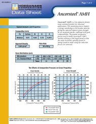
AncorLam ®<br />
Induction in Tesla<br />
AncorLam ® is a high performance insulated powder material suitable for a variety of soft magnetic<br />
applications. Specific applications include switching actuators and ignition coils, fuel injectors, and<br />
motor applications.<br />
AncorLam ® consists of high purity iron powder with a specialized coating/lubricant system that<br />
minimizes hysteresis and eddy current losses over a range of frequencies. This material is provided<br />
as a press-ready premix for warm or cold die compaction.<br />
AncorLam is a lower cost option giving good balance between Core Loss and Induction.<br />
Performance of AncorLam ® at 7.45 g/cm 3<br />
Induction at 40 kA/m (T) 1.90<br />
Induction at 10 kA/m (T) 1.47<br />
Maximum permeability 470<br />
Coercive field strength (A/m) 300<br />
Core-loss at 400 Hz, 1T, W/kg 67<br />
Core-loss 1 kHz, 1T, W/kg —<br />
Green density (g/cm3 ) 7.47<br />
Cured strength (MPa) 90<br />
Resistivity micro-ohm-meter >50<br />
Apparent density (g/cm3 ) 2.85-3.10<br />
Hall flow (s/50 g) 32 max<br />
HYSTERESIS LOOP<br />
AncorLam<br />
2.5<br />
2<br />
1.5<br />
1<br />
0.5<br />
0<br />
-5000 -4000 -3000 -2000 -1000 0 1000 2000 3000 4000 5000<br />
-0.5<br />
-1<br />
-1.5<br />
-2<br />
-2.5<br />
Applied Field in A/m
AncorLam ® (continued)<br />
Core-loss in Watts/kg<br />
Core-loss in Watts/kg<br />
10000<br />
1000<br />
100<br />
0.1<br />
0.01<br />
500<br />
450<br />
400<br />
350<br />
300<br />
250<br />
200<br />
150<br />
100<br />
50<br />
10<br />
1<br />
CORE-LOSS VS. INDUCTION<br />
60 Hz, 100 Hz, 200 Hz, 400 Hz, 1k Hz, 5k Hz, 10 kHz<br />
0.001<br />
0.001 0.01 0.1<br />
Induction in Tesla<br />
1 10<br />
PERMEABILITY VS. INDUCTION, FREQUENCY<br />
60 Hz, 100 Hz, 200 Hz, 400 Hz, 1000 Hz, 5000 Hz<br />
5000 Hz<br />
10 kHz<br />
0<br />
0 0.2 0.4 0.6 0.8 1 1.2 1.4 1.6 1.8 2<br />
60 Hz<br />
Induction in Tesla<br />
60 Hz<br />
10 kHz<br />
5 kHz<br />
1 kHz<br />
400 Hz<br />
200 Hz<br />
100 Hz<br />
60 Hz
AncorLam ® HR<br />
Induction in Tesla<br />
AncorLam ® HR has a constant permeability over a wide frequency range providing a lower cost<br />
option for high frequency applications.<br />
AncorLam ® HR consists of high purity iron powder with a specialized coating/lubricant system that<br />
minimizes hysteresis and eddy current losses over a range of frequencies. This material is provided<br />
as a press ready premix for warm or cold die compaction.<br />
Performance of AncorLam ® HR at 7.45 g/cm 3<br />
Induction at 40 kA/m (T) 1.90<br />
Induction at 10 kA/m (T) 1.52<br />
Maximum permeability 370<br />
Coercive field strength (A/m) 270<br />
Core-loss at 400 Hz, 1T, W/kg 53<br />
Core-loss 1 kHz, 1T, W/kg 147<br />
Green density (g/cm3 ) 7.45<br />
Cured strength (MPa) 60<br />
Resistivity micro-ohm-meter >1300<br />
Apparent density (g/cm3 ) 2.85-3.10<br />
Hall flow (s/50 g) 32 max<br />
HYSTERESIS LOOP<br />
AncorLam HR<br />
2.5<br />
2<br />
1.5<br />
1<br />
0.5<br />
0<br />
-5000 -4000 -3000 -2000 -1000 0 1000 2000 3000 4000 5000<br />
-0.5<br />
-1<br />
-1.5<br />
-2<br />
-2.5<br />
Applied Field in A/m
AncorLam ® HR (continued)<br />
Core-loss in Watts/kg<br />
Permeability<br />
10000<br />
1000<br />
400<br />
350<br />
300<br />
250<br />
200<br />
150<br />
100<br />
50<br />
100<br />
0<br />
10<br />
0.0001<br />
1<br />
0.1<br />
0.01<br />
0.001<br />
CORE-LOSS AT VARIOUS FREQUENCIES AND INDUCTION<br />
60 Hz, 100 Hz, 200 Hz, 400 Hz, 1000 Hz, 5000 Hz, 10000 Hz<br />
0.001 0.01 0.1 1 10<br />
PERMEABILITY AT VARIOUS FREQUENCIES<br />
60 Hz, 100 Hz, 200 Hz, 400 Hz, 1000 Hz, 5000 Hz, 10000 Hz<br />
10000 Hz<br />
Induction in Tesla<br />
0 0.4 0.8 1.2 1.6 2<br />
Induction in Tesla<br />
60 Hz<br />
10 kHz<br />
5 kHz<br />
1 kHz<br />
400 Hz<br />
200 Hz<br />
100 Hz<br />
60 Hz
AncorLam ® 2HR<br />
Induction in Tesla<br />
AncorLam ® 2 HR is bested suited for motor and actuator applications. Providing good induction and<br />
permeability for applications up to 1000 HZ.<br />
AncorLam ® 2 HR consists of high purity iron powder with a specialized coating/lubricant system that<br />
increase permeability while limiting losses. This material is provided as a press ready premix for<br />
warm or cold die compaction.<br />
Performance of AncorLam ® 2HR<br />
Induction at 40 kA/m (T) 2.02*<br />
Induction at 10 kA/m (T) 1.64*<br />
Maximum permeability 610*<br />
Coercive field strength (A/m) 246*<br />
Core-loss at 400 Hz, 1T, W/kg 52*<br />
Core-loss 1 kHz, 1T, W/kg 172*<br />
Green density (g/cm3 ) 7.60*<br />
Cured strength (MPa) 90*<br />
Resistivity micro-ohm-meter >475*<br />
Apparent density (g/cm3 ) 2.85-3.10*<br />
Hall flow (s/50 g)<br />
* Density is 7.6 g.cm<br />
32 max*<br />
3<br />
HYSTERESIS LOOP<br />
AncorLam 2HR*(7.6 DENSITY)<br />
2.5<br />
2<br />
1.5<br />
1<br />
0.5<br />
0<br />
-10000 -8000 -6000 -4000 -2000 0 2000 4000 6000 8000 10000<br />
-0.5<br />
-1<br />
-1.5<br />
-2<br />
-2.5<br />
Applied Field in A/m
AncorLam ® 2HR (continued)<br />
Core-loss in Watts/kg<br />
Permeability<br />
10000<br />
1000<br />
100<br />
10<br />
1<br />
0.1<br />
0.01<br />
0.001<br />
700<br />
600<br />
500<br />
400<br />
300<br />
200<br />
100<br />
0<br />
CORE-LOSS VS INDUCTION (7.6 DENSITY)<br />
60 Hz, 100 Hz, 200 Hz, 400 Hz, 1000 Hz, 5000 Hz, 10000 Hz<br />
0.0001<br />
0.01 0.1 1 10<br />
Induction in Tesla<br />
PERMEABILITY VS INDUCTION (7.6 DENSITY)<br />
60 Hz, 100 Hz, 400 Hz, 1000 Hz, 5000 Hz, 10000 Hz<br />
60 Hz<br />
10 kHz<br />
0 0.5 1 1.5 2 2.5<br />
Induction in Tesla<br />
10 kHz<br />
5 kHz<br />
1 kHz<br />
400 Hz<br />
200 Hz<br />
100 Hz<br />
60 Hz
AncorLam ® 2FHR<br />
Induction in Tesla<br />
AncorLam ® 2FHR is targeted and engineered for higher frequency applications up to 31 Khz.<br />
AncorLam ® 2FHR consists of high purity iron powder with a specialized coating/lubricant system that<br />
minimizes hysteresis and eddy current losses over a range of frequencies. This material is provided<br />
as a press ready premix for warm or cold die compaction.<br />
Performance of Ancorlam ® 2FHR at 7.45 g/cm 3<br />
Induction at 40 kA/m (T) 1.90<br />
Induction at 10 kA/m (T) 1.50<br />
Maximum permeability 360<br />
Coercive field strength (A/m) 300<br />
Core-loss at 400Hz, 1T, W/kg 54<br />
Core-loss 1kHz, 1T, W/kg 146<br />
Green density (g/cm3 ) 7.43<br />
Cured strength (MPa) 60<br />
Resistivity micro-ohm-meter >1300<br />
Apparent density (g/cm3 ) 2.85-3.10<br />
Hall flow (s/50 g) 32 max<br />
HYSTERESIS LOOP<br />
AncorLam 2FHR<br />
2.5<br />
2<br />
1.5<br />
1<br />
0.5<br />
0<br />
-5000 -4000 -3000 -2000 -1000 0 1000 2000 3000 4000 5000<br />
-0.5<br />
-1<br />
-1.5<br />
-2<br />
-2.5<br />
Applied Field in A/m
AncorLam ® 2FHR (continued)<br />
Core-loss in Watts/kg<br />
Permeability<br />
10000<br />
1000<br />
100<br />
10<br />
1<br />
0.1<br />
0.01<br />
400<br />
350<br />
300<br />
250<br />
200<br />
150<br />
100<br />
50<br />
0<br />
CORE-LOSS AT VARIOUS FREQUENCIES<br />
60 Hz, 100 Hz, 200 Hz, 400 Hz, 1000 Hz, 5000 Hz, 10000 Hz<br />
0.001<br />
0.001 0.01 0.1 1 10<br />
PERMEABILITY AT VARIOUS FREQUENCIES AND INDUCTION<br />
60 Hz, 100 Hz, 200 Hz, 400 Hz, 1000 Hz, 5000 Hz, 10000 Hz<br />
10000 Hz<br />
Induction in Tesla<br />
0 0.4 0.8 1.2 1.6 2<br />
Induction in Tesla<br />
60 Hz<br />
10 kHz<br />
5 kHz<br />
1 kHz<br />
400 Hz<br />
200 Hz<br />
100 Hz<br />
60 Hz
AncorLam ® 2<br />
AncorLam ® 2 is a high performance insulated powder material suitable for a variety of soft magnetic<br />
applications that require high permeability. Used for applications up to 400 HZ.<br />
Performance of AncorLam ® 2 at 7.45 g/cm 3<br />
Induction at 40 kA/m (T) 1.95<br />
Induction at 10 kA/m (T) 1.60<br />
Maximum permeability 550<br />
Coercive field strength (A/m) 245<br />
Core-loss at 400 Hz, 1T, W/kg 67<br />
Core-loss 1 kHz, 1T, W/kg 245<br />
Green density (g/cm3 ) 7.49<br />
Cured strength (MPa) 40<br />
Resistivity micro-ohm-meter >50<br />
Apparent density (g/cm3 ) 2.85-3.10<br />
Hall flow (s/50 g) 32 max<br />
Induction in Tesla<br />
DC HYSTERESIS LOOP<br />
AncorLam 2<br />
2.5<br />
2<br />
1.5<br />
1<br />
0.5<br />
0<br />
-5000 -4000 -3000 -2000 -1000 0 1000 2000 3000 4000 5000<br />
-0.5<br />
-1<br />
-1.5<br />
Applied Field in A/m<br />
-2<br />
-2.5<br />
Applied Field in A/m
AncorLam ® 2 (continued)<br />
Core-loss in Watts/kg<br />
Permeability<br />
10000<br />
1000<br />
600<br />
500<br />
400<br />
300<br />
200<br />
100<br />
100<br />
10<br />
1<br />
0.1<br />
0.01<br />
CORE-LOSS AT VARIOUS FREQUENCIES<br />
60 Hz, 100 Hz, 200 Hz, 400 Hz, 1000 Hz, 5000 Hz, 10000 Hz<br />
0.001<br />
0.001 0.01 0.1 1 10<br />
AC PERMEABILITY<br />
60 Hz, 100 Hz, 200 Hz, 400 Hz, 1000 Hz, 5000 Hz, 10000 Hz<br />
10000 Hz<br />
Induction in Tesla<br />
0<br />
0 0.5 1 1.5 2 2.5<br />
60 Hz<br />
Induction in Tesla<br />
10 kHz<br />
5 kHz<br />
1 kHz<br />
400 Hz<br />
200 Hz<br />
100 Hz<br />
60 Hz
RELEVANCE OF MATERIAL CHARACTERISTICS ON END-USE<br />
PERFORMANCE FOR ELECTROMAGNETIC DEVICES<br />
Permeability Influences the output power of<br />
the electrical device. Wrought lamination stacks<br />
represent two-dimensional values typically<br />
ranging between 1500 and 5000, whereas the<br />
isotropic IP grades approach ~500 permeability.<br />
Some conversions may necessitate higher input<br />
current to achieve similar flux density. However,<br />
3-dimensional flux paths provide greater design<br />
and performance flexibility. In addition, use of<br />
high-energy permanent magnet materials can<br />
compensate for the lower permeability of the<br />
soft magnetic composite grades.<br />
Induction Influences the ultimate torque<br />
capability of rotating machines. Lower values<br />
can be offset by increasing the backing section<br />
(material mass), while maintaining optimal<br />
component packaging associated with<br />
optimized end-winding and slot fill.<br />
Strength In some instances, components must<br />
withstand rotational forces, stresses associated<br />
with press fitting or compression joining, and<br />
have sufficient strength to accommodate the<br />
copper winding process during assembly.<br />
Appropriate polymer types and process<br />
conditions permit adequate strength to support<br />
application requirements.<br />
AC Frequency Preferred applications involve<br />
operating conditions of 200 Hz electrical<br />
frequency. This utilizes the benefits associated<br />
with the inherently low eddy current losses of<br />
I.P. materials.<br />
Core-Loss The two primary components of<br />
core-loss include eddy current and hysteresis<br />
losses. Greater core-loss values generally<br />
increase operating temperatures, which leads to<br />
additional losses. Lower loss values translate<br />
into greater electrical efficiencies. Losses can be<br />
minimized with proper particle coating, binder<br />
combinations and stress relief.<br />
Processing Conditions Various options exist<br />
depending upon the binder and/or lubricant<br />
combinations. Warm compaction, with or<br />
without powder heating, or conventional<br />
compaction can be used for a variety of<br />
applications.<br />
Base Iron Chemical composition and particle<br />
size, along with component density, can be<br />
manipulated to enhance specific magnetic<br />
performance characteristics.<br />
Curing Temperature A secondary thermal<br />
treatment enhances the binder strength and<br />
helps minimize internal stress promoting<br />
recovery of the iron powder crystal structure.<br />
Temperature optimization is required to limit<br />
internal stresses without destroying the binder<br />
characteristics.
MAGNETIC TERMINOLOGY<br />
Induction (B) is the magnetic flux per unit area,<br />
measured in Gauss. Sometimes referred to as<br />
flux density. This characteristic has a direct<br />
relationship with component density.<br />
Permeability (µ) essentially indicates the ease<br />
with which a material can be magnetized or its<br />
magnetic sensitivity – represents a ratio of flux<br />
density to magnetizing force.<br />
Coercive Field Strength (Hc ) is the<br />
demagnetizing force necessary to restore the<br />
magnetic induction to zero.<br />
Eddy Current Loss is the primary component<br />
of high frequency loss. Generally associated<br />
with electrical currents that create an opposing<br />
force to the magnetic flux when exposed to AC<br />
fields. Higher resistivity values are beneficial in<br />
minimizing eddy current losses.<br />
Hysteresis Loss represents the primary loss<br />
factor at lower frequency, and is primarily<br />
attributed to magnetic friction in the core. Wider<br />
and taller B-H loop areas generally represent<br />
greater hysteresis loss for a given material.<br />
Intrinsic Saturation is the point at which all the<br />
domains in the magnetic material become<br />
oriented in the same direction as the applied<br />
field energy.<br />
Magnetizing Force (H) is the applied energy to<br />
induce magnetic flux, measured in Oersteds.<br />
Hysteresis Curve is the measurement technique<br />
representing the closed circuit of a magnetic<br />
material subjected to positive and negative<br />
magnetizing forces – graphically represents<br />
the material’s magnetic characterization,<br />
i.e., saturation, residual induction and coercive<br />
field strength.<br />
Soft Magnetic components have the ability to<br />
both store or strengthen magnetic energy and<br />
allow for easy conversion back into electrical<br />
energy - often utilized to strengthen the<br />
magnetic flux of an electric device as a core<br />
product.<br />
Hard Magnets represent greater coercivity<br />
levels and are difficult to demagnetize, typically<br />
referred to as permanent magnets and<br />
represent a broad B-H curve band-width<br />
(>M.M.F.).<br />
Air Gap represents a low permeability gap<br />
(air space) in the flux path of a magnetic circuit,<br />
generally undesirable for energy transfer –<br />
however, can be beneficial to increase the<br />
ability to store energy in a core.<br />
Reluctance essentially represents magnetic<br />
circuit “resistance,” which is inversely<br />
proportional to permeability and directly<br />
proportional to magnetic circuit length.<br />
Ferrites are combinations of iron oxides with<br />
Mn, Zn, Ni used when high permeability and<br />
low eddy current losses are desirable, generally<br />
exhibit low saturation induction – generally used<br />
for high frequency 10 KHz to 1 GHz applications.<br />
Laminations are low carbon steel or silicon-iron<br />
grades made in thin strips with insulation<br />
coating positioned between layered stacks,<br />
extensively used in low 60 Hz electric motor<br />
applications because of low cost and design<br />
familiarity.<br />
Iron <strong>Powder</strong> Cores share some characteristics<br />
with <strong>Insulated</strong> <strong>Powder</strong> grades. They are<br />
primarily used for energy storage, transformers<br />
and inductors in various consumer products.<br />
Q Factor is a means of determining the<br />
effectiveness of an iron core – represents a ratio<br />
of the increase in effective inductance to the<br />
increase in the equivalent resistance of the<br />
magnetic circuit: Q = I / R (I= increase in test<br />
coil inductance, R = core-losses).<br />
Hysteresis curve<br />
representative<br />
of a soft magnet<br />
material
Hoeganaes Corporation<br />
1001 Taylors Lane<br />
Cinnaminson, NJ 08077-2017<br />
Phone: 856.829.2220 • Fax: 856.786.2574<br />
www.hoeganaes.com<br />
© 2010 Hoeganaes Corp. All Rights Reserved. Form HEG-750-P