industry relay - Elesta Elektrotechnik AG
industry relay - Elesta Elektrotechnik AG
industry relay - Elesta Elektrotechnik AG

You also want an ePaper? Increase the reach of your titles
YUMPU automatically turns print PDFs into web optimized ePapers that Google loves.
<strong>Elesta</strong> <strong>Elektrotechnik</strong> <strong>AG</strong> <strong>industry</strong> <strong>relay</strong>s and accessories<br />
edition 2003
technical data has been fully checked, but accuracy of printed matter not guaranteed<br />
2 Catalog 2002 e / 04.03<br />
table of contents<br />
SKR-<strong>industry</strong> <strong>relay</strong> 4<br />
SKR-screw socket with accessories 14<br />
SFR-<strong>industry</strong> <strong>relay</strong> 16<br />
SFR-screw socket with accessories 27<br />
LR-power <strong>relay</strong> 28<br />
FR-miniature <strong>relay</strong> 34<br />
PR-PCB <strong>relay</strong> 42<br />
MR-special <strong>relay</strong> 48
product range<br />
SKR line<br />
- <strong>industry</strong> <strong>relay</strong><br />
- standard 10 A<br />
- plug-in <strong>relay</strong> 2-pole<br />
- plug-in <strong>relay</strong> 3-pole<br />
FR line<br />
- miniature <strong>relay</strong> 4 A<br />
- PCB version<br />
- PCB <strong>relay</strong> 6 A<br />
- forcibly actuated<br />
- PCB version<br />
- double contact<br />
SFR line<br />
FR line socket LR line<br />
- <strong>industry</strong> <strong>relay</strong><br />
- standard 5 A<br />
- plug-in <strong>relay</strong> 4-pole<br />
- matching FR line - power <strong>relay</strong><br />
PR line MR line<br />
- universal <strong>relay</strong><br />
- soldering version<br />
- plug-in version 8-pole<br />
- plug-in version 11-pole<br />
- high impedance, sensitive coil<br />
catalog 2002 e / 04.03 3
the universal <strong>relay</strong> SKR<br />
The strengths of the SKR <strong>industry</strong><br />
<strong>relay</strong> lie in the mature and thoughtout<br />
construction.<br />
Over-average contact safety and life<br />
time, electrical and mechanical status<br />
indication as well as the unsurpassed<br />
construction from only six<br />
assemblies makes the <strong>relay</strong> to the<br />
excellent power switch.<br />
features<br />
• simple construction<br />
• high contact load<br />
• contact spring in Beryllium<br />
bronze<br />
• safe wire diameter<br />
• long life time<br />
• large coil room<br />
4 catalog 2002 e / 04.03<br />
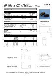
SKR - <strong>industry</strong> <strong>relay</strong><br />
the time module STM the socket<br />
8 adjustable functions and 8 selectable<br />
time ranges: these are the<br />
special features of the time module<br />
STM. With only one version of the<br />
module all essential features as<br />
operating voltage, functions and<br />
time ranges are adjustable.<br />
The result: a simple and cost-effective<br />
warehousing.<br />
• electrical or mechanical status<br />
indication<br />
• integrated manual actuation<br />
• simple installation<br />
• indelible scheme on socket or<br />
cover following international<br />
standards<br />
Simple to handle screw-terminal<br />
and clear, rich in contrast labeled<br />
clamp identification, are the base<br />
for a problemles use.<br />
The ZKE/ZKX sockets permit a rapid<br />
and secure installation.<br />
The separated inputs and outputs<br />
are located at one level. There is<br />
also the possibility to plug a time<br />
module STM or other additional<br />
modules together with the SKR<br />
<strong>relay</strong>.<br />
applications<br />
• mostly used where a timedependent<br />
event must be<br />
headed<br />
• switch panel making<br />
• machine <strong>industry</strong><br />
• illuminations<br />
• locking of functions<br />
• gate control<br />
• machine control
type number key<br />
SKR 115 A ... 024VDC<br />
order samples<br />
manual actuation<br />
position indication<br />
free wheel diode<br />
LED display<br />
coil voltage<br />
VDC = direct current<br />
VAC = alternating current<br />
standard voltage<br />
VAC: 024, 115, 230 V<br />
VDC: 024, 110<br />
options<br />
D=double contact (AgCuNi)<br />
L = electrical position indication<br />
F = free wheel diode<br />
FL= free wheel diode and<br />
electrical position indication<br />
B = without manual actuation<br />
T = push-button actuation<br />
C = current coil<br />
<strong>relay</strong> version<br />
SKR 085 A<br />
SKR 115 A<br />
SKR 122 A<br />
A = mechanical position indication<br />
standard: manual actuation<br />
• • SKR085 A VDC/AC SKR115 A VDC/AC SKR122 A VDC/AC<br />
• • • SKR085 AF VDC SKR115 AF VDC SKR122 AF VDC<br />
• • • SKR085 AL VDC/AC SKR115 AL VDC/AC SKR122 AL VDC/AC<br />
• • • • SKR085 AFL VDC SKR115 AFL VDC SKR122 AFL VDC<br />
catalog 2002 e / 04.03 5
order numbers<br />
serial version SKR 085 A ...<br />
VDC/AC<br />
with mechanical position indication<br />
options<br />
electrical<br />
position indication SKR 085 L ..<br />
with free wheel diode SKR 085 F ..<br />
electrical<br />
position indication<br />
with free wheel diode SKR 085 FL ..<br />
double contact SKR 085 D ..<br />
without manual<br />
actuation SKR 085 B ..<br />
push-button actuation SKR 085 T ..<br />
current coil SKR 085 C ..<br />
(combinations with mechanical and electrical position<br />
indication and free-wheel diode are possible)<br />
accessories<br />
plug-in socket ZVE 8<br />
ZKE 088<br />
metal clamp ZKR 008<br />
6 catalog 2002 e / 04.03<br />
SKR085 - <strong>industry</strong> <strong>relay</strong>, 8-pole<br />
Industry <strong>relay</strong> with two change-over<br />
contacts in different versions.<br />
contact specifications<br />
contact material AgCuNi<br />
contact type single contact<br />
nominal switching capacity 250 VAC 10 A AC1 2500 VA<br />
440 VAC 4 A AC1<br />
electric life expectancy app. 700'000 operations<br />
250 VAC, 10 A, AC1 (360 operations/h)<br />
inrush current max. 40 A for 200 ms<br />
switching current range 50 mA to 10 A<br />
switching power range 0,3 VA(W) to 2500 VA<br />
general data<br />
mechanic life expectancy > 10 8 operations<br />
mechanical switching frequency 20 Hz<br />
pull-in time 12 ms at DC / 3-10 ms at AC<br />
release time 3,5 ms at DC / 2-15 ms at AC<br />
bounce time normally open contact 3,5 ms at DC / 3-6 ms at AC<br />
bounce time break contact 9 ms at DC / 6-11 ms at AC<br />
shock resistance AK: > 10 g<br />
vibration resistance 10-55 Hz, AK: 10 g, RK: 3 g<br />
test voltage, coil/contact 2500 Veff<br />
test voltage, open contact 1500 Veff<br />
insulation resistance 10 12 Ohm<br />
weight app. 80 g<br />
installation situation any<br />
ambient temperature max. +70 °C<br />
protection standard IP 40<br />
tests, instructions<br />
certificates UL, CSA, VDE<br />
insulation group VDE 0110 / group C 250 VAC
14<br />
A1<br />
3<br />
2<br />
dimensions<br />
coil specifications<br />
12 22<br />
4 5<br />
11<br />
circuit diagram<br />
UB nominal voltage<br />
UN rated voltage<br />
3,0<br />
2,5<br />
2,0<br />
1,5<br />
1,0<br />
0,5<br />
1<br />
8<br />
21<br />
6<br />
7<br />
24<br />
A2<br />
energizing voltage range<br />
2<br />
1<br />
0 20 40 60 70<br />
ambient temperature °C<br />
DC-<strong>relay</strong><br />
AC-<strong>relay</strong><br />
- single <strong>relay</strong>, no heat concentration<br />
by surrounding components with<br />
self-heating.<br />
- on time 100%<br />
1) max. energizing voltage without<br />
contact load<br />
2) min. energizing voltage (guaranteed<br />
value), without operation in advance.<br />
35 48<br />
standard coils for direct current (other voltages on enquiry)<br />
13<br />
10<br />
rated pull-in reset nominal resistance<br />
voltage voltage voltage current Ohm tolerance<br />
VDC at 20 °C at 20 °C mA at 20 °C %<br />
12 9,6 ≥ 0,6 104 115 +/-10<br />
24 19,2 ≥ 1,2 50,0 480 +/-10<br />
48 38,4 ≥ 2,4 25,9 1850 +/-10<br />
110 88,0 ≥ 5,5 12,2 9'000 +/-15<br />
220 176,0 ≥ 11 7,58 29'000 +/-15<br />
standard coils for alternated current (other voltages on enquiry)<br />
VAC<br />
12 9,6 ≥ 0,6 211 13,3 +/-10<br />
24 19,2 ≥ 1,2 104 52 +/-10<br />
48 38,4 ≥ 2,4 55 240 +/-10<br />
110 88,0 ≥ 5,5 23 1'120 +/-10<br />
220 176 ≥ 11,0 12,0 4'450 +/-10<br />
230 184 ≥ 11,5 11,5 5'600 +/-10<br />
35<br />
catalog 2002 e / 04.03 7
order numbers<br />
serial version SKR 115 A ...<br />
VDC/AC<br />
with mechanical position indication<br />
options<br />
electrical<br />
position indication SKR 115 L ..<br />
with free wheel diode SKR 115 F ..<br />
electrical<br />
position indication<br />
with free wheel diode SKR 115 FL ..<br />
double contact SKR 115 D ..<br />
without manual<br />
actuation SKR 115 B ..<br />
push-button actuation SKR 115 T ..<br />
current coil SKR 115 C ..<br />
(combinations with mechanical and electrical position<br />
indication and free-wheel diode are possible)<br />
accessories<br />
plug-in socket ZVE 11<br />
ZKE 118<br />
ZKX 118<br />
time module STM 100<br />
metal clamp ZKR 008<br />
8 catalog 2002 e / 04.03<br />
SKR115 - <strong>industry</strong> <strong>relay</strong>, 11-pole<br />
Industry <strong>relay</strong> with three changeover<br />
contacts in different versions<br />
contact specifications<br />
contact material AgCuNi<br />
contact type single contact<br />
nominal switching capacity 250 VAC 10 A AC1 2500 VA<br />
440 VAC 4 A AC1<br />
electric life expectancy app. 700'000 operations<br />
250 VAC, 10 A, AC1 (360 operations/h)<br />
max. inrush current 40 A for 200 ms<br />
switching current range 50 mA to 10 A<br />
switching power range 0,3 VA to 2500 VA<br />
general data<br />
mechanic life expectancy > 10 8 operations<br />
mechanical switching frequency 20 Hz<br />
pull-in time 12 ms at DC / 3-10 ms at AC<br />
release time 3,5 ms at DC / 2-15 ms at AC<br />
bounce time normally open contact 3,5 ms at DC / 3-6 ms at AC<br />
bounce time break contact 9 ms at DC / 6-11 ms at AC<br />
shock resistance AK: > 10 g<br />
vibration resistance 10-55 Hz, AK: 10 g, RK: 3 g<br />
test voltage, coil/contact 2500 Veff<br />
test voltage, open contact 1500 Veff<br />
insulation resistance 10 12 Ohm<br />
weight app. 80 g<br />
installation situation any<br />
ambient temperature max. +70 °C<br />
protection standard IP 40<br />
tests, instructions<br />
certificates UL, CSA, VDE<br />
insulation group VDE 0110 / group C 250 VAC
22<br />
12 32<br />
4<br />
8<br />
dimensions<br />
coil specifications<br />
5<br />
21<br />
6<br />
3<br />
9<br />
14<br />
34<br />
2<br />
10<br />
A1<br />
1 11<br />
A2<br />
11 31<br />
circuit diagram<br />
UB nominal voltage<br />
UN rated voltage<br />
3,0<br />
2,5<br />
2,0<br />
1,5<br />
1,0<br />
0,5<br />
2<br />
1<br />
- single <strong>relay</strong>, no heat concentration<br />
by surrounding components with<br />
self-heating.<br />
- on time 100%<br />
1) max. energizing voltage without<br />
contact load<br />
2) min. energizing voltage (guaranteed<br />
value), without operation in advance.<br />
7<br />
24<br />
energizing voltage range<br />
0 20 40 60 70<br />
ambient temperature °C<br />
DC-<strong>relay</strong><br />
AC-<strong>relay</strong><br />
35 48<br />
standard coils for direct current (other voltages on enquiry)<br />
13<br />
10<br />
rated pull-in reset nominal resistance<br />
voltage voltage voltage current Ohm tolerance<br />
VDC at 20 °C at 20 °C mA at 20 °C %<br />
12 9,6 ≥ 0,6 104 115 +/-10<br />
24 19,2 ≥ 1,2 50,0 480 +/-10<br />
48 38,4 ≥ 2,4 25,9 1850 +/-10<br />
110 88,0 ≥ 5,5 12,2 9'000 +/-15<br />
220 176,0 ≥ 11 7,58 29'000 +/-15<br />
standard coils for alternated current (other voltages on enquiry)<br />
VAC<br />
12 9,6 ≥ 0,6 211 13,3 +/-10<br />
24 19,2 ≥ 1,2 104 52 +/-10<br />
48 38,4 ≥ 2,4 55 240 +/-10<br />
110 88,0 ≥ 5,5 23 1'120 +/-10<br />
220 176 ≥ 11,0 12,0 4'450 +/-10<br />
230 184 ≥ 11,5 11,5 5'600 +/-10<br />
35<br />
catalog 2002 e / 04.03 9
order numbers<br />
serial version SKR 122 A ...<br />
VDC/AC<br />
with mechanical position indication<br />
options<br />
electrical<br />
position indication SKR 122 L ..<br />
with free wheel diode SKR 122 F ..<br />
electrical<br />
position indication<br />
with free wheel diode SKR 22 FL ..<br />
double contact SKR 122 D ..<br />
without manual<br />
actuation SKR 122 B ..<br />
push-button actuation SKR 122 T ..<br />
current coil SKR 122 C ..<br />
(combinations with mechanical and electrical position<br />
indication and free-wheel diode are possible)<br />
accessories<br />
PCB socket ZKR 003<br />
metal clamp ZKR 008<br />
10 catalog 2002 e / 04.03<br />
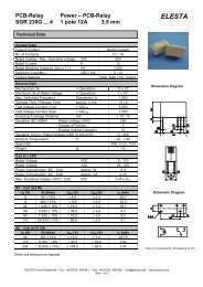
SKR122 - <strong>industry</strong> <strong>relay</strong>, PCB version<br />
Industry <strong>relay</strong> with three changeover<br />
contacts in different versions<br />
contact specifications<br />
contact material AgCuNi<br />
contact type single contact<br />
nominal switching capacity 250 VAC 10 A AC1 2500 VA<br />
440 VAC 4 A AC1<br />
electric life expectancy app. 700'000 operations<br />
250 VAC, 10 A, AC1 (360 operations/h)<br />
max. inrush current 40 A for 200 ms<br />
switching current range 50 mA to 10 A<br />
switching power range 0,3 VA to 2500 VA<br />
general data<br />
mechanic life expectancy > 10 8 operations<br />
mechanical switching frequency 20 Hz<br />
pull-in time 12 ms at DC / 3-10 ms at AC<br />
release time 3,5 ms at DC / 2-15 ms at AC<br />
bounce time normally open contact 3,5 ms at DC / 3-6 ms at AC<br />
bounce time break contact 9 ms at DC / 6-11 ms at AC<br />
shock resistance AK: > 10 g<br />
vibration resistance 10-55 Hz, AK: 10 g, RK: 3 g<br />
test voltage, coil/contact 2500 Veff<br />
test voltage, open contact 1500 Veff<br />
insulation resistance 10 12 Ohm<br />
weight app. 80 g<br />
installation situation any<br />
ambient temperature max. +70 °C<br />
tests, instructions<br />
certificates UL, CSA, VDE<br />
insulation group VDE 0110 / group C 250 VAC
a<br />
12 22 32<br />
14 24 34<br />
11 21 31<br />
circuit diagram<br />
dimensions<br />
coil specifications<br />
UB nominal voltage<br />
UN rated voltage<br />
3,0<br />
2,5<br />
2,0<br />
1,5<br />
1,0<br />
0,5<br />
b<br />
energizing voltage range<br />
2<br />
1<br />
0 20 40 60 70<br />
ambient temperature °C<br />
DC-<strong>relay</strong><br />
AC-<strong>relay</strong><br />
- single <strong>relay</strong>, no heat concentration<br />
by surrounding components with<br />
self-heating.<br />
- on time 100%<br />
1) max. energizing voltage without<br />
contact load<br />
2) min. energizing voltage (guaranteed<br />
value), without operation in advance.<br />
10,16 10,16<br />
12<br />
1,3 ±0,1<br />
25,4<br />
35<br />
37<br />
25,4<br />
1,2 x 0,8<br />
5,08<br />
7,62<br />
10,16<br />
48<br />
6<br />
5,08<br />
7,62<br />
30,48<br />
30,48<br />
38,5<br />
drilling plan (view on solder side)<br />
standard coils for direct current (other voltages on enquiry)<br />
35<br />
rated pull-in reset nominal resistance<br />
voltage voltage voltage current Ohm tolerance<br />
VDC at 20 °C at 20 °C mA at 20 °C %<br />
12 9,6 ≥ 0,6 104 115 +/-10<br />
24 19,2 ≥ 1,2 50,0 480 +/-10<br />
48 38,4 ≥ 2,4 25,9 1850 +/-10<br />
110 88,0 ≥ 5,5 12,2 9'000 +/-15<br />
220 176,0 ≥ 11 7,58 29'000 +/-15<br />
standard coils for alternated current (other voltages on enquiry)<br />
VAC<br />
12 9,6 ≥ 0,6 211 13,3 +/-10<br />
24 19,2 ≥ 1,2 104 52 +/-10<br />
48 38,4 ≥ 2,4 55 240 +/-10<br />
110 88,0 ≥ 5,5 23 1'120 +/-10<br />
220 176 ≥ 11,0 12,0 4'450 +/-10<br />
230 184 ≥ 11,5 11,5 5'600 +/-10<br />
catalog 2002 e / 04.03<br />
11
AgCuNi single contact<br />
current (A)<br />
number of operations<br />
10<br />
8<br />
6<br />
4<br />
3<br />
2<br />
1<br />
0,8<br />
0,6<br />
0,4<br />
0,3<br />
0,2<br />
load limit curve for DC<br />
0,1<br />
0 50 100 150 200 250<br />
voltage (VDC)<br />
1) inductive load, L/R 40 ms<br />
2) resitive load<br />
8<br />
7<br />
6<br />
5<br />
4<br />
3<br />
2<br />
106 1 2<br />
contact life time<br />
12 catalog 2002 e / 04.03<br />
1<br />
3 4 5 6 7 8<br />
2<br />
9 10 A<br />
switching current (A)<br />
- AC load cos phi 1 (AC1)<br />
- 250 VAC 50 Hz 360 operations/h<br />
AgCuNi double contact<br />
current (A)<br />
number of operations<br />
10<br />
8<br />
6<br />
4<br />
3<br />
2<br />
1<br />
0,8<br />
0,6<br />
0,4<br />
0,3<br />
0,2<br />
load limit curve for DC<br />
1<br />
0,1<br />
0 50 100 150 200 250<br />
voltage (VDC)<br />
1) inductive load, L/R 40 ms<br />
2) resitive load<br />
8<br />
7<br />
6<br />
5<br />
4<br />
3<br />
2<br />
105 1 2<br />
contact life time<br />
3 4 5 6 7 8<br />
switching current (A)<br />
- AC load cos phi 1 (AC1)<br />
- 250 VAC 50 Hz 360 operations/h<br />
2<br />
SKR-contact specifications<br />
data valid for <strong>relay</strong> SKR 085<br />
SKR 115<br />
SKR 122<br />
contact material AgCuNi (Ag1,88 Ni0,12)<br />
contact type single contact<br />
nominal switching capacity 250 VAC 10 A AC1 2500 VA<br />
440 VAC 4 A AC1 1600 VA<br />
electric life expectancy app. 700'000 operations<br />
250 VAC 10 A AC1 (360 operations/h)<br />
max. inrush current 40 A for 20 ms<br />
switching current range 30 mA to 10 A<br />
switching power range 0,18 VA to 2500 VA<br />
contact resistance 20 mΩ<br />
data valid for <strong>relay</strong> SKR 085D<br />
SKR 115D<br />
SKR 122D<br />
contact material AgCuNi (Ag1,88 Ni0,12)<br />
contact type double contact<br />
nominal switching capacity 250 VAC 6 A AC1 1500 VA<br />
electric life expectancy app. 150'000 operations<br />
250 VAC 6 A AC1 (360 operations/h)<br />
max. inrush current 15 A für 20 ms<br />
switching current range 10 mA to 6 A<br />
switching power range 0,06 VA to 1500 VA<br />
contact resistance 10 mΩ
ZKR-PCB socket with accessories<br />
order numbers<br />
ZKR 003<br />
accessories<br />
metal clamp<br />
ZKR 008<br />
dimensions<br />
3,5<br />
37 5,4<br />
ZKR 003 matching to SKR 122<br />
general data<br />
nominal data max. 10 A 400 V<br />
test voltage 2000 Veff<br />
contact spring material Ms improved<br />
fixing soldering pin 1 x M3<br />
creeping resistance CTI 250<br />
weight app. 7 g<br />
installation situation any<br />
ambient temperature -40 to +85 °C<br />
number of poles 11-pole<br />
protection standard IP 30<br />
tests, instructions<br />
certificates UL, CSA<br />
insulation group VDE 0110 / group C 250 VAC<br />
1,0x0,3<br />
11<br />
38,5<br />
drilling plan<br />
2,5 / 2,54<br />
10,16<br />
1,3<br />
25,4<br />
37<br />
10,16<br />
view from solder side<br />
7,62 5,08<br />
catalog 2002 e / 04.03<br />
30,48<br />
38,5<br />
13
socket<br />
data<br />
data<br />
14 catalog 2002 e / 04.03<br />
ZVE8 ZKE088<br />
nominal data 400 VAC 10 A 400 VAC 10 A<br />
dimensions (L x B x H) [mm] 57 x 38 x 28,5 75 x 38 x 26<br />
ambient temperature [°C] -40 to +85 -40 to +85<br />
accessories<br />
plug-in modules E...<br />
time module STM 100<br />
metal clamp ZKR008 ZKR008<br />
ZVE11 ZKX118 ZKE118<br />
nominal data 400 VAC 10 A 400 VAC 10 A 400 VAC 10 A<br />
dimensions (L x B x H) [mm] 57 x 38 x 28,5 62 x 38 x 26 75 x 38 x 26<br />
ambient temperature [°C] -40 to +85 -40 to +85 -40 to +85<br />
accessories<br />
SKR-screw socket with accessories<br />
plug-in modules E...<br />
time modules STM 100<br />
metal clamp ZKR008 ZKR008 ZKR008<br />
tests, instructions<br />
certificates UL, CSA<br />
insulation group VDE 0110 / group C 250 VAC
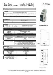
time modules<br />
STM 100<br />
general data<br />
plug-in modules<br />
E...<br />
data<br />
compatible to socket ZKE088/118<br />
function programmable<br />
time range 0,05s - 240h<br />
rated voltage 24 - 240 VDC/VAC<br />
time range 8 ranges: 1s, 10s, 1m, 10m, 1h, 10h, 1d, 10d<br />
time adjustment variable, 5% - 100% of the time range<br />
time function 8 functions, selectable by DIP switches<br />
display green LED for ON-status, blinking at time delay<br />
dimensions B x H x T = 35 x 46,7 x 10,3 mm (without clamp)<br />
weight app. 14 g<br />
permissible ambient temperature -25 to +55 °C<br />
nominal voltage 24V to 240V AC (-15%...+10%) , 24V to 250V DC (-15%...+10%)<br />
frequency 48 Hz to 63 Hz<br />
max. power consumption 24V AC/DC: 70mW , 240V AC/DC: 700mW<br />
min. impulse time (B1) AC: 50ms, DC: 30 ms<br />
min. pause time (B1) AC&DC: 100ms at 25°C, AC&DC: 140ms at 55°C<br />
pull-in delay AC: max. 40ms, DC: 20ms<br />
reset time delay AC&DC: max. 100ms at 25°C, AC&DC: max. 140ms at 55°C<br />
control voltage 24V: min. 80% of supply voltage<br />
230V: min. 95% of supply voltage<br />
time delay after power loss max. 10ms<br />
start-up time 60ms<br />
re-readiness time max. 100ms at 25°C, max. 150ms at 55°C<br />
reset at UN ≤ 10Veff<br />
precision at the scale stops ±0,5%<br />
repeatability
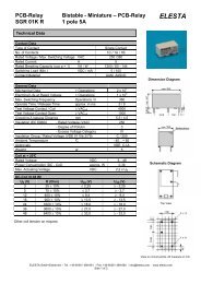
the SFR-<strong>industry</strong> <strong>relay</strong><br />
SFR <strong>industry</strong> <strong>relay</strong>s are the ideal <strong>relay</strong>s<br />
for control systems.<br />
features<br />
• large contacts (ø 3 mm)<br />
• extraordinary life time<br />
• mechanical lever integrated in the<br />
cover<br />
16 catalog 2002 e / 04.03<br />
SFR - <strong>industry</strong> <strong>relay</strong><br />
A simple construction guarantees the<br />
safety of these <strong>relay</strong>s. The large contact<br />
rivet (ø 3 mm) guarantees the extraordinary<br />
life time.<br />
• large separating walls between the<br />
contacts guarantees high creeping<br />
and leakage distance<br />
• mechanical position indication<br />
• complete accessory<br />
• all <strong>relay</strong>s are 100% computer tested<br />
An ideal product for control systems in<br />
combination with the socket program<br />
and the accessories.<br />
applications<br />
• switch panel making<br />
• machine and plant <strong>industry</strong><br />
• switching between functions
type number key<br />
SFR 143 A 024VDC<br />
order samples<br />
manual actuation<br />
position indication<br />
free wheel diode<br />
LED display<br />
coil voltages<br />
024 VAC 024 VDC<br />
115 VAC 110 VDC<br />
230 VAC<br />
(other voltage ranges on enquiry)<br />
option<br />
A = mechanical position indication<br />
F = free wheel diode<br />
L = electrical position indication<br />
<strong>relay</strong> version<br />
SFR 142/082 PCB version<br />
SFR 143/083 plug-in version<br />
standard: manual actuation<br />
• • SFR082 A VDC/AC SFR 142 A VDC/AC SFR 083 A VDC/AC SFR 143 A VDC/AC<br />
• • • SFR082 AF VDC SFR 142 AF VDC SFR 083 AF VDC SFR 143 AF VDC<br />
• • • SFR082 AL VDC/AC SFR 142 AL VDC/AC SFR 083 AL VDC/AC SFR 143 AL VDC/AC<br />
• • • • SFR082 AFL VDC SFR 142 AFL VDC SFR 083 AFL VDC SFR 143 AFL VDC<br />
catalog 2002 e / 04.03 17
order numbers<br />
SFR 143 A ..VDC/AC<br />
option<br />
electrical position indication<br />
SFR 143 AL ..VDC/AC ....<br />
accessories<br />
screw socket ES15/4N<br />
18 catalog 2002 e / 04.03<br />
SFR - Industry <strong>relay</strong>, 4-pole<br />
number of contacts 4 WK<br />
switching current range 50 mA to 5 A<br />
inrush current 15 A<br />
specialities mechanical position indication<br />
mechanical actuation with lever<br />
contact specifications<br />
contact material AgCuNi<br />
contact type single contact<br />
nominal switching capacity 250 VAC 5 A AC1 1250 VA<br />
440 VAC 4 A AC1<br />
electric life expectancy app. 200'000 operations<br />
250 VAC, 5 A, AC1 (360 operations/h)<br />
max. inrush current 15 A for 20 ms<br />
switching current range 50 mA to 5 A<br />
switching power range 0,3 VA to 1760 VA<br />
general data<br />
mechanic life expectancy 10 x 10 6 operations<br />
mechanical switching frequency 20 Hz<br />
pull-in time 8 ms at DC / 3-9 ms at AC<br />
release time 3,5 ms at DC / 4-12 ms at AC<br />
bounce time normally open contact 3,0 ms at DC / 1-8 ms at AC<br />
bounce time break contact 8 ms at DC / 9-16 ms at AC<br />
shock resistance AK: > 10 g<br />
test voltage, coil/contact 2000 Veff<br />
test voltage, set of contacts/set of contacts 2000 Veff<br />
test voltage, open contact 1000 Veff<br />
insulation resistance 250 MΩ<br />
creeping resistance CTI 250<br />
weight app. 34 g<br />
installation situation any<br />
ambient temperature -40 to +70 °C<br />
protection standard IP 40<br />
tests, instructions<br />
certificates VDE<br />
insulation group VDE 0110 / group C 250 VAC
1 2 3 4<br />
5 6 7 8<br />
9 10 11 12<br />
13 14<br />
circuit diagram<br />
dimensions<br />
coil specifications<br />
UB nominal voltage<br />
UN rated voltage<br />
3,0<br />
2,5<br />
2,0<br />
1,5<br />
1,0<br />
0,5<br />
energizing voltage range<br />
2<br />
1<br />
0 20 40 60 80 100<br />
ambient temperature °C<br />
DC-<strong>relay</strong><br />
AC-<strong>relay</strong><br />
- single <strong>relay</strong>, no heat concentration by<br />
surrounding components with self-heating.<br />
- on time 100%<br />
1) max. energizing voltage without contact<br />
load<br />
2) min. energizing voltage (guaranteed value),<br />
without operation in advance.<br />
35<br />
3,4<br />
4,55<br />
4,05<br />
6,35<br />
28,7<br />
standard coils for direct current (other voltages on enquiry)<br />
rated pull-in reset nominal resistance<br />
voltage voltage voltage current Ohm tolerance<br />
VDC at 20 °C at 20 °C mA at 20 °C %<br />
12 9,0 ≥ 0,6 70,60 170 +/-10<br />
24 18,0 ≥ 1,2 37,21 645 +/-10<br />
48 36,0 ≥ 2,4 18,46 2'600 +/-10<br />
110 82,5 ≥ 5,5 8,33 13'200 +/-15<br />
standard coils for alternated current (other voltages on enquiry)<br />
VAC<br />
7,4<br />
0,5<br />
6,35<br />
3,65<br />
20,5<br />
= = =<br />
2<br />
13,2 3,65<br />
12 9,0 ≥ 1,8 105,3 39 +/-10<br />
24 18,0 ≥ 3,6 51,6 165 +/-10<br />
48 36,0 ≥ 7,2 26,0 650 +/-10<br />
110 82,5 ≥ 16,5 12,9 3'500 +/-10<br />
230 172,5 ≥ 34,5 5,9 15'000 +/-15<br />
catalog 2002 e / 04.03 19
order numbers<br />
SFR 083 A ..VDC/AC<br />
options<br />
electrical position indication<br />
SFR 083 AL ..VDC/AC ....<br />
accessories<br />
screw socket ES15/2<br />
20 catalog 2002 e / 04.03<br />
SFR - <strong>industry</strong> <strong>relay</strong>, 2-pole<br />
number of contacts 2 WK<br />
switching current range 50 mA to 5 A<br />
inrush current 15 A<br />
specialities mechanical position indication<br />
mechanical actuation with lever<br />
contact specifications<br />
contact material AgCuNi<br />
contact type single contact<br />
nominal switching capacitiy 250 VAC 5 A AC1 1250 VA<br />
440 VAC 4 A AC1<br />
electric life expectancy app. 200'000 operations<br />
250 VAC, 5 A, AC1 (360 operations/h)<br />
max. inrush current 15 A for 20 ms<br />
switching current range 50 mA to 5 A<br />
switching power range 0,3 VA to 1760 VA<br />
general data<br />
mechanic life expectancy 10 x 10 6 operations<br />
mechanical switching frequency 20 Hz<br />
pull-in time 8 ms at DC / 3-9 ms at AC<br />
release time 3,5 ms at DC / 4-12 ms at AC<br />
bounce time normally open contact 3,0 ms at DC / 1-8 ms at AC<br />
bounce time break contact 8 ms at DC / 9-16 ms at AC<br />
shock resistance AK: > 10 g<br />
test voltage, coil/contact 2000 Veff<br />
test voltage, set of contacts/set of contacts 2000 Veff<br />
test voltage, open contact 1000 Veff<br />
insulation resistance 250 MΩ<br />
creeping resistance CTI 250<br />
weight app. 34 g<br />
installation situation any<br />
ambient temperature -40 to +70 °C<br />
protection standard IP 40<br />
tests, instructions<br />
certificates VDE<br />
insultions group VDE 0110 / group C 250 VAC
1<br />
5<br />
9<br />
12<br />
13 14<br />
circuit diagram<br />
dimensions<br />
coil specifications<br />
UB nominal voltage<br />
UN rated voltage<br />
3,0<br />
2,5<br />
2,0<br />
1,5<br />
1,0<br />
0,5<br />
4<br />
8<br />
energizing voltage range<br />
2<br />
1<br />
0 20 40 60 80 100<br />
ambient temperature °C<br />
DC-<strong>relay</strong><br />
AC-<strong>relay</strong><br />
- single <strong>relay</strong>, no heat concentration by<br />
surrounding components with self-heating.<br />
- on time 100%<br />
1) max. energizing voltage without contact<br />
load<br />
2) min. energizing voltage (guaranteed value),<br />
without operation in advance.<br />
35<br />
3,4<br />
4,55<br />
4,05<br />
6,35<br />
standard coils for direct current (other voltages on enquiry)<br />
rated pull-in reset nominal resistance<br />
voltage voltage voltage current Ohm tolerance<br />
VDC at 20 °C at 20 °C mA at 20 °C %<br />
12 9,0 ≥ 0,6 70,60 170 +/-10<br />
24 18,0 ≥ 1,2 37,21 645 +/-10<br />
48 36,0 ≥ 2,4 18,46 2'600 +/-10<br />
110 82,5 ≥ 5,5 8,33 13'200 +/-15<br />
standard coils for alternated current (other voltages on enquiry)<br />
VAC<br />
28,7<br />
7,4<br />
0,5<br />
6,35<br />
3,65<br />
20,5<br />
2<br />
13,2 3,65<br />
12 9,0 ≥ 1,8 105,3 39 +/-10<br />
24 18,0 ≥ 3,6 51,6 165 +/-10<br />
48 36,0 ≥ 7,2 26,0 650 +/-10<br />
110 82,5 ≥ 16,5 12,9 3'500 +/-10<br />
230 172,5 ≥ 34,5 5,9 15'000 +/-15<br />
catalog 2002 e / 04.03 21
order numbers<br />
SFR 142 A ..VDC/AC<br />
options<br />
electrical position indication<br />
SFR 142 AL ..VDC/AC ....<br />
22 catalog 2002 e / 04.03<br />
SFR - <strong>industry</strong> <strong>relay</strong>, PCB version<br />
number of contacts 4 WK<br />
switching current range 50 mA bis 5 A<br />
inrush current 15 A<br />
specialities mechanical position indication<br />
mechanical actuation with lever<br />
contact specifications<br />
contact material AgCuNi<br />
contact type single contact<br />
nominal switching capacitiy 250 VAC 5 A AC1 1250 VA<br />
440 VAC 4 A AC1<br />
electric life expectancy app. 200'000 operations<br />
250 VAC, 5 A, AC1 (360 operations/h)<br />
max. inrush current 15 A for 20 ms<br />
switching current range 50 mA to 5 A<br />
switching power range 0,3 VA to 1760 VA<br />
general data<br />
mechanic life expectancy 10 x 10 6 operations<br />
mechanical switching frequency 20 Hz<br />
pull-in time 8 ms at DC / 3-9 ms at AC<br />
release time 3,5 ms at DC / 4-12 ms at AC<br />
bounce time normally open contact 3,0 ms at DC / 1-8 ms at AC<br />
bounce time break contact 8 ms at DC / 9-16 ms at AC<br />
shock resistance AK: > 10 g<br />
test voltage, coil/contact 2000 Veff<br />
test voltage, set of contacts/set of contacts 2000 Veff<br />
test voltage, open contact 1000 Veff<br />
insulation resistance 250 MΩ<br />
creeping resistance CTI 250<br />
weight app. 34 g<br />
installation situation any<br />
ambient temperature -40 to +70 °C<br />
protection standard IP 40<br />
tests, instructions<br />
certificates VDE<br />
insultions group VDE 0110 / group C 250 VAC
1 2 3 4<br />
5 6 7 8<br />
9 10 11 12<br />
13 14<br />
circuit diagram<br />
dimensions<br />
coil specifications<br />
UB nominal voltage<br />
UN rated voltage<br />
3,0<br />
2,5<br />
2,0<br />
1,5<br />
1,0<br />
0,5<br />
35<br />
3,4<br />
4,55<br />
4,05<br />
6,35<br />
28,7<br />
energizing voltage range<br />
2<br />
1<br />
7,4<br />
0,5<br />
6,35<br />
0 20 40 60 80 100<br />
ambient temperature °C<br />
DC-<strong>relay</strong><br />
AC-<strong>relay</strong><br />
- single <strong>relay</strong>, no heat concentration by<br />
surrounding components with self-heating.<br />
- on time 100%<br />
1) max. energizing voltage without contact<br />
load<br />
2) min. energizing voltage (guaranteed value),<br />
without operation in advance.<br />
3,65<br />
standard coils for direct current (other voltages on enquiry)<br />
rated pull-in reset nominal resistance<br />
voltage voltage voltage current Ohm tolerance<br />
VDC at 20 °C at 20 °C mA at 20 °C %<br />
12 9,0 ≥ 0,6 70,60 170 +/-10<br />
24 18,0 ≥ 1,2 37,21 645 +/-10<br />
48 36,0 ≥ 2,4 18,46 2'600 +/-10<br />
110 82,5 ≥ 5,5 8,33 13'200 +/-15<br />
standard coils for alternated current (other voltages on enquiry)<br />
VAC<br />
20,5<br />
= = =<br />
1<br />
13,2 3,65<br />
drilling plan<br />
12 9,0 ≥ 1,8 105,3 39 +/-10<br />
24 18,0 ≥ 3,6 51,6 165 +/-10<br />
48 36,0 ≥ 7,2 26,0 650 +/-10<br />
110 82,5 ≥ 16,5 12,9 3'500 +/-10<br />
230 172,5 ≥ 34,5 5,9 15'000 +/-15<br />
catalog 2002 e / 04.03 23
order numbers<br />
SFR 082 A ..VDC/AC<br />
options<br />
electrical position indication<br />
SFR 082 AL ..VDC/AC ....<br />
24 catalog 2002 e / 04.03<br />
SFR - <strong>industry</strong> <strong>relay</strong>, PCB version<br />
number of contacts 2 WK<br />
switching current range 50 mA bis 5 A<br />
inrush current 15 A<br />
specialities mechanical position indication<br />
mechanical actuation with lever<br />
contact specifications<br />
contact material AgCuNi<br />
contact type single contact<br />
nominal switching capacitiy 250 VAC 5 A AC1 1250 VA<br />
440 VAC 4 A AC1<br />
electric life expectancy app. 200'000 operations<br />
250 VAC, 5 A, AC1 (360 operations/h)<br />
max. inrush current 15 A for 20 ms<br />
switching current range 50 mA to 5 A<br />
switching power range 0,3 VA to 1760 VA<br />
general data<br />
mechanic life expectancy 10 x 10 6 operations<br />
mechanical switching frequency 20 Hz<br />
pull-in time 8 ms at DC / 3-9 ms at AC<br />
release time 3,5 ms at DC / 4-12 ms at AC<br />
bounce time normally open contact 3,0 ms at DC / 1-8 ms at AC<br />
bounce time break contact 8 ms at DC / 9-16 ms at AC<br />
shock resistance AK: > 10 g<br />
test voltage, coil/contact 2000 Veff<br />
test voltage, set of contacts/set of contacts 2000 Veff<br />
test voltage, open contact 1000 Veff<br />
insulation resistance 250 MΩ<br />
creeping resistance CTI 250<br />
weight app. 34 g<br />
installation situation any<br />
ambient temperature -40 to +70 °C<br />
protection standard IP 40<br />
tests, instructions<br />
certificates VDE<br />
insultions group VDE 0110 / group C 250 VAC
1<br />
5<br />
9<br />
12<br />
13 14<br />
circuit diagram<br />
dimensions<br />
coil specifications<br />
UB nominal voltage<br />
UN rated voltage<br />
3,0<br />
2,5<br />
2,0<br />
1,5<br />
1,0<br />
0,5<br />
4<br />
8<br />
35<br />
3,4<br />
4,55<br />
4,05<br />
6,35<br />
energizing voltage range<br />
2<br />
1<br />
28,7<br />
7,4<br />
0 20 40 60 80 100<br />
ambient temperature °C<br />
DC-<strong>relay</strong><br />
AC-<strong>relay</strong><br />
- single <strong>relay</strong>, no heat concentration by<br />
surrounding components with self-heating.<br />
- on time 100%<br />
1) max. energizing voltage without contact<br />
load<br />
2) min. energizing voltage (guaranteed value),<br />
without operation in advance.<br />
0,5<br />
6,35<br />
3,65<br />
standard coils for direct current (other voltages on enquiry)<br />
rated pull-in reset nominal resistance<br />
voltage voltage voltage current Ohm tolerance<br />
VDC at 20 °C at 20 °C mA at 20 °C %<br />
12 9,0 ≥ 0,6 70,60 170 +/-10<br />
24 18,0 ≥ 1,2 37,21 645 +/-10<br />
48 36,0 ≥ 2,4 18,46 2'600 +/-10<br />
110 82,5 ≥ 5,5 8,33 13'200 +/-15<br />
standard coils for alternated current (other voltages on enquiry)<br />
VAC<br />
20,5<br />
1<br />
13,2 3,65<br />
drilling plan<br />
12 9,0 ≥ 1,8 105,3 39 +/-10<br />
24 18,0 ≥ 3,6 51,6 165 +/-10<br />
48 36,0 ≥ 7,2 26,0 650 +/-10<br />
110 82,5 ≥ 16,5 12,9 3'500 +/-10<br />
230 172,5 ≥ 34,5 5,9 15'000 +/-15<br />
catalog 2002 e / 04.03 25
AgCuNi single contact<br />
current (A)<br />
8<br />
6<br />
4<br />
3<br />
2<br />
1<br />
0,8<br />
0,6<br />
0,4<br />
0,3<br />
0,2<br />
0,1<br />
0 50 100 150 200 250<br />
number of operations<br />
load limit curve for DC<br />
resitive load<br />
voltage (VDC)<br />
8<br />
7<br />
6<br />
5<br />
4<br />
3<br />
2<br />
105 contact life time<br />
1 2<br />
3 4 5 6 7 8<br />
switching current (A)<br />
- AC-load cos phi 1 (AC1)<br />
- 250 VAC 50 Hz 360 operations/h<br />
26 catalog 2002 e / 04.03<br />
SFR - contact specifications<br />
data valid for <strong>relay</strong> SFR 143<br />
contact material AgCuNi (Ag1,88 Ni0,12)<br />
contact type single contact<br />
nominal switching capacity 250 VAC 5 A AC1 1250 VA<br />
440 VAC 4 A AC1<br />
electric life expectancy app. 200'000 operations<br />
250 VAC 5 A AC1 (360 operations/h)<br />
inrush current max. 15 A for 20 ms<br />
switching current range 50 mA to 5 A<br />
switching power range 0,3 VA to 2500 VA<br />
contact resistance 20 mΩ
SFR - screw socket with accessories<br />
socket<br />
ES15/4N<br />
plug-in modules<br />
E...<br />
data<br />
nominal data 300 VAC 12 A<br />
dimensions (L x B x H) [mm] 66 x 29,5 x 29<br />
ambient temperature [°C] -40 to +85<br />
accessories<br />
plug-in modules E...<br />
metal clamp Clip MHO<br />
plastic clamp Clip MS35<br />
data<br />
compatible to socket ES15/4N<br />
free wheel diode 230 VDC E22<br />
RC-circuit 240 VAC E52C<br />
LED 24 - 60 VAC/DC E62EV<br />
LED 110 - 230 VAC/DC E92V<br />
catalog 2002 e / 04.03 27
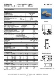
the power <strong>relay</strong> LR<br />
LR <strong>relay</strong>s are power <strong>relay</strong>s which convince<br />
by her brilliant simplicity. The<br />
mature and simple construction will predestine<br />
this <strong>relay</strong> for the rough and<br />
uncompromising use.<br />
features<br />
• simple construction<br />
• high switching power<br />
• low coil power<br />
• extraordinary life time<br />
• DIN rail mountable<br />
28 catalog 2002 e / 04.03<br />
LR-power <strong>relay</strong><br />
By using best materials and because of<br />
the simple construction a max. mechanical<br />
and electrical life time was achieved.<br />
applications<br />
• switching of short-circuit runner<br />
engines<br />
• radiators in household appliance<br />
• radiators in electromechanical ovens<br />
The special advantages of this mature<br />
<strong>relay</strong> lie in the high switching power as<br />
well as in the low power consumption<br />
of the coil.<br />
The LR <strong>relay</strong> is available in AC- and also<br />
in DC- version
type number key<br />
LR 024 VDC<br />
order sample<br />
coil voltage<br />
VDC = direct current<br />
VAC = alternating current<br />
standard voltage<br />
VAC: 024, 230 V<br />
VDC: 024, 110<br />
<strong>relay</strong> version<br />
LR 230 VAC - 3 normally open contacts<br />
- coil voltage 230 VAC<br />
- AMP connections<br />
- DIN-rail installation<br />
LR<br />
catalog 2002 e / 04.03 29
order numbers<br />
serial version LR 220 VAC<br />
LR 24 VDC<br />
30 catalog 2002 e / 04.03<br />
LR - power <strong>relay</strong><br />
Power <strong>relay</strong>s especially for switching<br />
high AC- loads.<br />
contact specifications (see data sheet for curves)<br />
contact material AgCdO<br />
contact type single contact<br />
nominal switching capacity 250 VAC 20A AC1 5000 VA<br />
400 VAC 15A AC1<br />
electric life expectancy app. 900'000 operations<br />
250 VAC 20A AC1 (360 Schaltung/h)<br />
inrush current max. 50A for 200 ms<br />
switching current range 500mA to 20A<br />
switching power range 8VA(W) to 5000VA<br />
general data<br />
max. switching frequency mechanical 15<br />
mechanic life expectancy 20 Mio.<br />
pull-in time 13 ms (VDC) /6-14 ms (VAC)<br />
release time 2,5 ms (VDC) /3-12 ms (VAC)<br />
bounce time 2 ms (VDC) /3 - 8 ms (VAC)<br />
shock resistance AK: 10 g<br />
test voltage, coil/contact 2’500 Veff<br />
test voltage, open contact 2’500 Veff<br />
insulation resistance >10 12 Ohm<br />
weight 120 g<br />
installation situation any<br />
ambient temperature max. +60 °C<br />
tests, instructions<br />
certificates CSA, VDE<br />
insulation group VDE 0110 / group C 250 VAC
2<br />
4<br />
6<br />
circuit diagram<br />
dimensions<br />
coil specifications<br />
UB<br />
UN<br />
3,0<br />
2,5<br />
2,0<br />
1,5<br />
1,0<br />
0,5<br />
energizing voltage range<br />
2<br />
1<br />
a<br />
b<br />
0 20 40 60 80 100<br />
ambient temperature °C<br />
DC-<strong>relay</strong><br />
AC-<strong>relay</strong><br />
- single <strong>relay</strong>, no heat concentration by<br />
surrounding components with self-heating.<br />
- on time 100%<br />
1) max. energizing voltage without contact<br />
load<br />
2) min. energizing voltage (guaranteed value),<br />
without operation in advance.<br />
1<br />
3<br />
5<br />
2<br />
4<br />
6<br />
20 16<br />
52<br />
a<br />
b<br />
ø 4,5<br />
4,5<br />
42<br />
1<br />
3<br />
5<br />
AMP connection side<br />
42<br />
44<br />
5<br />
0,8x6,3<br />
standard coils for direct current (other voltages on enquiry)<br />
55<br />
rated pull-in reset nominal resistance<br />
voltage voltage voltage current Ohm tolerance<br />
VDC at 20 °C at 20 °C mA at 20 °C %<br />
12 9 ≥ 0,6 114 105 +/-10<br />
24 18 ≥ 1,2 58,5 410 +/-10<br />
48 36 ≥ 2,4 30,0 1'600 +/-10<br />
110 82,5 ≥ 5,5 13,8 8'000 +/-10<br />
standard coils for alternated current (other voltages on enquiry)<br />
VAC<br />
12 10,2 ≥ 0,6 260 10 +/-10<br />
24 20,4 ≥ 1,2 130 40 +/-10<br />
48 40,8 ≥ 2,4 60 180 +/-10<br />
110 93,5 ≥ 5,5 29 950 +/-10<br />
220 187 ≥ 11 14 3'900 +/-10<br />
catalog 2002 e / 04.03 31
AgCdO<br />
Ι [A]<br />
1 indicutive load L/R = 40 ms<br />
2 resitive load<br />
number of operations<br />
10<br />
8<br />
6<br />
4<br />
3<br />
2<br />
1<br />
0,8<br />
0,6<br />
0,4<br />
0,3<br />
0,2<br />
0,1<br />
0 50 100 150 200 250<br />
4<br />
3<br />
2<br />
10<br />
8<br />
6<br />
5<br />
4<br />
3<br />
2<br />
6<br />
10 5<br />
max. DC breaking capacity<br />
1<br />
2<br />
voltage [V] U =<br />
contact life time<br />
for AC-load cos ϕ = 1<br />
2 4 6 8 10 12 14 16 18 20<br />
1: for 220 VAC (1-phase)<br />
- I < 10 A, max. 360 operations/h<br />
- I > 10 A, max. 180 operations/h<br />
2: for 3 x 380 VAC (3-phase, star- or<br />
triangle circuit)<br />
- I < 10 A, max. 360 operations/h<br />
- I > 10 A, max. 180 operations/h<br />
32 catalog 2002 e / 04.03<br />
1<br />
2<br />
AC-load [A] Ι ∼<br />
LR - contact specifications<br />
data valid for <strong>relay</strong> LR<br />
contact material AgCdO<br />
contact type single contact<br />
nominal switching capacity 250VAC 20A AC1 5000VA<br />
400VAC 15A AC1<br />
electric life expectancy app. 900'000 operations<br />
250 VAC 20A AC1 (360 Schaltung/h)<br />
inrush current max. 50A for 200 ms<br />
switching current range 500mA to 20A<br />
switching power range 8VA(W) to 5000VA(W)
catalog 2002 e / 04.03 33
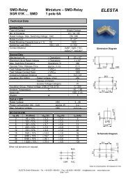
the FR-miniature <strong>relay</strong><br />
FR <strong>relay</strong>s are available with three or four<br />
change-over contacts. They are used as<br />
fail-save elements in industrial electronics,<br />
automation and control.<br />
features<br />
• large product range<br />
• simple, robust construction<br />
• high switching power<br />
• extraordinary life time<br />
• high contact force<br />
• flexible installation<br />
• contact spring in Beryllium bronze<br />
34 catalog 2002 e / 04.03<br />
FR - miniature <strong>relay</strong><br />
applications<br />
• devices of automation and control
type number key<br />
FR 11 P 024 VDC .....<br />
order samples<br />
options<br />
switching current: 4A<br />
contact material: AgCuNi (4A)<br />
AgCuNi+Au4-6µm<br />
coil voltage<br />
VDC = direct current<br />
VAC = alternating current<br />
standard voltage<br />
VAC: 024, 110, 230 V<br />
VDC: 024, 110<br />
PCB version<br />
<strong>relay</strong> version<br />
FR 11<br />
FR 14<br />
FR 11 P 024 VDC 4A - 3 change-over contacts<br />
- PCB version<br />
- coil voltage 24VDC<br />
- nominal switching current 4 A<br />
FR 14 P 230 VAC 4A - 4 change-over contacts<br />
- PCB version<br />
- coil voltage 230VAC<br />
- nominal switching current 4A<br />
catalog 2002 e / 04.03 35
order numbers<br />
PCB version FR11P..VDC/VAC<br />
options<br />
contact material AgCuNi<br />
AgCuNi+Au10µm<br />
(see data sheet for contacts)<br />
accessories<br />
PCB socket ZB 87<br />
metal clamp ZFR004<br />
36 catalog 2002 e / 04.03<br />
FR 11P - miniature <strong>relay</strong><br />
Miniaturised PCB-<strong>relay</strong> with three<br />
change-over contacts for industrial<br />
electronics.<br />
contact specifications (see data sheet for curves)<br />
contact material AgCuNi<br />
contact type single contact<br />
nominal switching capacity 250 VAC 4 A AC1 500 VA<br />
electric life expectancy app. 150'000 operations<br />
250 VAC 2A AC1 (360 Schaltung/h)<br />
inrush current max. 15A for 200 ms<br />
switching current range 50 mA to 2A<br />
switching power range 0,3VA(W) to 500VA<br />
general data<br />
mechanic life expectancy > 50 x 10 6 operations<br />
mechanical switching frequency 20 Hz<br />
pull-in time 8 ms at DC / 3-9 ms at AC<br />
release time 2,5 ms at DC / 4-12 ms at AC<br />
bounce time normally open contact 3 ms at DC / 1-8 ms at AC<br />
bounce time break contact 8 ms at DC / 3-16 ms at AC<br />
shock resistance AK: >10 g<br />
test voltage, coil/contact 2'000 Veff<br />
test voltage, open contact 1'000 Veff<br />
insulation resistance 250 MΩ<br />
weight 35 g<br />
installation situation any<br />
ambient temperature max. +60 °C<br />
tests, instructions<br />
certificates UL, CSA, VDE
10<br />
7<br />
4<br />
1<br />
FR 11P<br />
8<br />
5<br />
2<br />
dimensions<br />
coil specifications<br />
11<br />
9<br />
6<br />
3<br />
circuit diagram drilling plan (view on solder side)<br />
standard coils for direct current<br />
(other voltages on enquiry)<br />
standard coils for alternated current<br />
(other voltages on enquiry)<br />
FR 11P<br />
1,3<br />
7<br />
5,5<br />
8,2<br />
5,1<br />
5,1<br />
FR 11P<br />
29 20,5<br />
34,8<br />
5,2<br />
7 8,2 5,1 5,1<br />
7 5,5<br />
1,0x0,5<br />
32<br />
8<br />
rated pull-in reset nominal resistance<br />
voltage voltage voltage current Ohm tolerance<br />
VDC at 20 °C at 20 °C mA at 20 °C %<br />
12 10,2 ≥ 0,6 82,7 145 +/-10<br />
24 20,4 ≥ 1,2 41,3 580 +/-10<br />
36 30,6 ≥ 1,8 26,6 1'350 +/-10<br />
48 40,8 ≥ 2,4 22,8 2'100 +/-10<br />
110 93,5 ≥ 5,5 11,5 9'500 +/-15<br />
VAC<br />
12 10,2 ≥ 0,6 105 39 +/-10<br />
24 20,4 ≥ 1,2 51,6 165 +/-10<br />
36 30,6 ≥ 1,8 32,7 373 +/-10<br />
48 40,8 ≥ 2,4 26,0 650 +/-10<br />
110 93,5 ≥ 5,5 12,9 3'500 +/-15<br />
220 187 ≥ 11,0 6,1 14'500 +/-15<br />
230 195 ≥ 11,5 5,8 15'000 +/-15<br />
catalog 2002 e / 04.03 37
order numbers<br />
PCB version FR14P..VDC/VAC<br />
options<br />
contact material AgCuNi<br />
AgCuNi+Au10µm<br />
(see data sheet for contacts)<br />
accessories<br />
PCB socket ZB 107<br />
metal clamp ZFR004<br />
38 catalog 2002 e / 04.03<br />
FR 14P - miniature <strong>relay</strong><br />
Miniaturised PCB-<strong>relay</strong> with three<br />
change-over contacts for industrial<br />
electronics.<br />
contact specifications (see data sheet for curves)<br />
contact material AgCuNi<br />
contact type single contact<br />
nominal switching capacity 250 VAC 4 A AC1 1000 VA<br />
electric life expectancy app. 200'000 operations<br />
250 VAC 4A AC1 (360 operations/h)<br />
inrush current max. 15A for 200 ms<br />
switching current range 50 mA to 4A<br />
switching power range 0,3VA to 1000VA<br />
general data<br />
mechanic life expectancy > 50 x 10 6 operations<br />
switching frequency mechanical 20 Hz<br />
pull-in time 8 ms at DC / 3-9 ms at AC<br />
release time 2,5 ms at DC / 4-12 ms at AC<br />
bounce time normally open contact 3 ms at DC / 1-8 ms at AC<br />
bounce time break contact 8 ms at DC / 3-16 ms at AC<br />
shock resistance AK: >10 g<br />
test voltage, coil/contact 2'000 Veff<br />
test voltage, open contact 1'000 Veff<br />
insulation resistance 250 MΩ<br />
weight 38 g<br />
installation situation any<br />
ambient temperature max. +60 °C<br />
tests, instructions<br />
certificates UL, CSA, VDE
13 14<br />
9<br />
5 6 7<br />
1<br />
dimensions<br />
FR 14P<br />
10<br />
2<br />
11<br />
3<br />
12<br />
8<br />
4<br />
circuit diagram drilling plan (view on solder side)<br />
coil specifications<br />
standard coils for direct current<br />
(other voltages on enquiry)<br />
standard coils for alternated current<br />
(other voltages on enquiry)<br />
7<br />
1,3<br />
29<br />
8,2 5,1 5,1<br />
FR 14P<br />
5,5 7<br />
34,8<br />
5,2<br />
5,5<br />
FR 14P<br />
5,1 5,1 8,2<br />
1,0x0,5<br />
26<br />
5,5 7 5,5<br />
8<br />
32<br />
rated pull-in reset nominal resistance<br />
voltage voltage voltage current Ohm tolerance<br />
VDC at 20 °C at 20 °C mA at 20 °C %<br />
12 10,2 ≥ 0,6 109 110 +/-10<br />
24 20,4 ≥ 1,2 52,1 460 +/-10<br />
36 30,6 ≥ 1,8 36,0 1'000 +/-10<br />
48 40,8 ≥ 2,4 28,2 1'700 +/-10<br />
110 93,5 ≥ 5,5 11,5 9'500 +/-15<br />
VAC<br />
12 10,2 ≥ 0,6 148 30 +/-10<br />
24 20,4 ≥ 1,2 68,5 130 +/-10<br />
36 30,6 ≥ 1,8 46,7 300 +/-10<br />
48 40,8 ≥ 2,4 35,5 540 +/-10<br />
110 93,5 ≥ 5,5 16,4 2’900 +/-15<br />
220 187 ≥ 11,0 6,1 14'500 +/-15<br />
230 195 ≥ 11,5 5,8 15'000 +/-15<br />
catalog 2002 e / 04.03 39
AgCuNi 4A<br />
Ι<br />
[A]<br />
7<br />
6<br />
5<br />
4<br />
3<br />
2<br />
1<br />
0<br />
Imax=4A<br />
- resitive load<br />
load limit curve for DC<br />
AgCuNi+Au 10µm<br />
Ι<br />
[A]<br />
7<br />
6<br />
5<br />
4<br />
3<br />
2<br />
1<br />
0<br />
- resitive load<br />
50 100 150 200<br />
U<br />
[V=]<br />
load limit curve for DC<br />
Imax=4A<br />
50 100 150 200<br />
U<br />
[V=]<br />
40 catalog 2002 e / 04.03<br />
FR - contact specifications<br />
data valid for <strong>relay</strong> FR 11<br />
FR 14<br />
contact material AgCuNi (AgCu 1,88 Ni0,12)<br />
contact type single contact<br />
nominal switching capacity 250VAC 4A AC1 1000VA<br />
electric life expectancy app. 200'000 operations<br />
250 VAC 4A AC1 (360 operations/h)<br />
inrush current max. 15A for 200 ms<br />
switching current range 50mA to 4A<br />
switching power range 0,3VA to 1000VA<br />
data valid for <strong>relay</strong> FR 11<br />
FR 14<br />
contact material AgCuNi+Au 10µm<br />
contact type single contact<br />
nominal switching capacity 250VAC 2A AC1 500VA<br />
electric life expectancy app. 100'000 operations<br />
250 VAC 2A AC1 (360 operations/h)<br />
inrush current max. 6A for 200 ms<br />
switching current range 10mA to 2A<br />
switching power range 0,06VA to 500VA
catalog 2002 e / 04.03 41
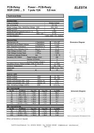
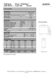
the PR-PCB <strong>relay</strong><br />
PCB-Relay from the PR family are small<br />
<strong>relay</strong>s. The version has forced guided<br />
contacts, 2 normally open contacts, 2<br />
normally closed contacts.<br />
features<br />
• simple fail-save construction<br />
• high switching power<br />
• high load current<br />
• extraordinary life time<br />
• high contact force<br />
• security distance according to VDE<br />
and CSA<br />
• minimal dimensions<br />
• the forced guided contact version,<br />
SUVA approved.<br />
42 catalog 2002 e / 04.03<br />
PR - PCB <strong>relay</strong><br />
In the industrial electronic as well as in<br />
the control <strong>industry</strong> they are used as<br />
fail-save elements.<br />
The forced guided contact version are<br />
often used in control systems of high<br />
safe applications.<br />
applications<br />
• devices of automation and control<br />
By using best materials and because of<br />
the simple construction the highest failsecurity<br />
was achieved.<br />
High precision in mechanical and electrical<br />
control guarantees the high and<br />
stable quality of the <strong>relay</strong>s.
type number key<br />
PR 4 ... 024 VDC<br />
order sample<br />
coil voltage<br />
VDC = direct current<br />
standard voltage<br />
VDC: 024, 110<br />
option<br />
F = flat version<br />
H = tall version<br />
<strong>relay</strong> version<br />
PR 4 (forced guided contacts)<br />
PR 4 F 024 VDC - PCB-<strong>relay</strong> with forced guided<br />
contacts<br />
- flat version<br />
- coil voltage 24 VDC<br />
catalog 2002 e / 04.03 43
order numbers<br />
serial version PR 4F .. VDC<br />
44 catalog 2002 e / 04.03<br />
PR 4F - PCB <strong>relay</strong><br />
PCB-<strong>relay</strong> with forced guided contacts, flat<br />
version with 2 normally open contacts,<br />
and 2 normally closed contacts<br />
contact specifications (see data sheet for curves)<br />
contact material AgCuNi<br />
contact type single contact<br />
nominal switching capacity 250 VAC 6 A AC1 1500 VA<br />
electric life expectancy app. 100'000 operations<br />
250 VAC 6A AC1 (360 Schaltung/h)<br />
inrush current 15 A for 200 ms<br />
switching current range 50 mA to 6A<br />
switching power range 0,3VA to 1500VA<br />
general data<br />
mechanic life expectancy > 20 x 10 6 operations<br />
mechanical switching frequency 20 Hz<br />
pull-in time 10 ms<br />
release time 2,5 ms<br />
bounce time normally open contact 6 ms<br />
bounce time break contact 6 ms<br />
test voltage, coil/contact 2'000 Veff / 50 Hz<br />
test voltage, open contact 1'500 Veff<br />
insulation resistance 2x10 11 Ohm<br />
weight 30 g<br />
installation situation any<br />
ambient temperature max. +60 °C<br />
tests, instructions<br />
certificates CSA, VDE, SUVA
circuit diagram (view from the top) drilling plan (view on solder side)<br />
dimensions<br />
coil specifications<br />
45,1<br />
36,4<br />
27,9<br />
7x2,54<br />
2,5 20,3 7x2,54<br />
5,08<br />
3,0<br />
45,1<br />
ø 1,3 mm ± 0,1<br />
20,3<br />
36,4<br />
1x0,2<br />
5,08<br />
27,9<br />
standard coils for direct current (other voltages on enquiry)<br />
2,5<br />
rated pull-in reset nominal resistance<br />
voltage voltage voltage current Ohm tolerance<br />
VDC at 20 °C at 20 °C mA at 20 °C %<br />
6 5,1 ≥ 0,3 222 27 +/-10<br />
12 10,2 ≥ 0,6 109 110 +/-10<br />
24 20,4 ≥ 1,2 54,5 440 +/-10<br />
48 40,8 ≥ 2,4 30 1'600 +/-10<br />
110 93,5 ≥ 5,5 10,3 10'600 +/-13<br />
12,2<br />
3,0<br />
3,0<br />
catalog 2002 e / 04.03 45
order numbers<br />
serial version PR4H .. VDC<br />
46 catalog 2002 e / 04.03<br />
PR 4H - PCB <strong>relay</strong><br />
PCB-<strong>relay</strong> with forced guided contacts, tall<br />
version with 2 normally open contacts,<br />
and 2 normally closed contacts<br />
contact specifications (see data sheet for curves)<br />
contact material AgCuNi<br />
contact type single contact<br />
nominal switching capacity 250 VAC 6 A AC1 1500 VA<br />
electric life expectancy app. 100'000 operations<br />
250 VAC 6A AC1 (360 operations/h)<br />
inrush current max. 15 A for 200 ms<br />
switching current range 50 mA to 6A<br />
switching power range 0,3VA to 1500VA<br />
general data<br />
mechanic life expectancy > 20 x 10 6 operations<br />
mechanical switching frequency 20 Hz<br />
pull-in time 10 ms<br />
release time 2,5 ms<br />
bounce time normally open contact 6 ms<br />
bounce time break contact 6 ms<br />
test voltage, coil/contact 2'000 Veff / 50 Hz<br />
test voltage, open contact 1'500 Veff<br />
insulation resistance 2x10 11 Ohm<br />
weight 30 g<br />
installation situation any<br />
ambient temperature max. +60 °C<br />
tests, instructions<br />
certificates CSA, VDE, SUVA
dimensions<br />
coil specifications<br />
contact specifications (AgCuNi 6A single contact)<br />
current (A)<br />
10<br />
8<br />
6<br />
4<br />
3<br />
2<br />
1<br />
0,8<br />
0,6<br />
0,4<br />
0,3<br />
0,2<br />
1<br />
DC breaking capacity<br />
1) inductive load, L/R 40 ms<br />
2) resitive load<br />
2<br />
0,1<br />
0 50 100 150 200 250<br />
voltage (VDC)<br />
2,9 20,3 7x2,54<br />
45,5<br />
ø 1,3 mm ± 0,1<br />
7x2,54 20,3<br />
45,5<br />
circuit diagram (view from the top) drilling plan (view on solder side)<br />
1x0,2<br />
2,9<br />
standard coils for direct current (other voltages on enquiry)<br />
7,62<br />
13,3<br />
36,1<br />
3,0<br />
rated min. pull-in release nominal resistance<br />
voltage voltage voltage current Ohm tolerance<br />
VDC at 20 °C at 20 °C mA at 20 °C %<br />
6 5,1 ≥ 0,3 222 27 +/-10<br />
12 10,2 ≥ 0,6 109 110 +/-10<br />
24 20,4 ≥ 1,2 54,5 440 +/-10<br />
48 40,8 ≥ 2,4 30 1'600 +/-10<br />
110 93,5 ≥ 5,5 10,3 10'600 +/-13<br />
data valid for <strong>relay</strong> PR 4F<br />
PR 4H<br />
contact material AgCuNi (AgCu1,8Ni0,12)<br />
contact type single contact<br />
nominal switching capacity 250VAC 6A AC1 1500VA<br />
electric life expectancy app. 100'000 operations<br />
250 VAC 6A AC1 (360 operations/h)<br />
inrush current max. 15A for 200 ms<br />
switching current range* 50mA to 6A<br />
switching power range* 0,3VA(W) to 1500VA(W)<br />
contact resistance ≤ 120mΩ in the new condition<br />
*typical values<br />
7,62<br />
2,9<br />
2,9<br />
13,3<br />
catalog 2002 e / 04.03 47
the special <strong>relay</strong> MR<br />
MR <strong>relay</strong>s are fail-save and universal<br />
useable elements with excellent<br />
contact load and high pull-in sensitivity.<br />
The big bobbin and the variability of the<br />
contacts make a lot of versions for different<br />
applications possible.<br />
applications<br />
• industrial electronics<br />
• automation and control<br />
48 catalog 2002 e / 04.03<br />
MR - special <strong>relay</strong><br />
features<br />
• different versions enable the ideal adaption for different applications.<br />
• short contact springs enable bounce-free switching.<br />
• special synthetic–layers and a substantial over-travel are the reasons for the constancy<br />
and safety at a large number of operations, also in bad climate conditions.
order numbers<br />
soldering version MRL<br />
... VDC/ VAC<br />
plug-in version<br />
8-pole MR8 ...VDC/ VAC<br />
plug-in version<br />
14-pole MR ...VDC/ VAC<br />
options<br />
contact material AgCuNi<br />
contact versions up to 6 pairs optionally<br />
accessories<br />
socket 8-pole ZKR 088<br />
socket 14-pole ZB 35<br />
metal clamp MR8 ZFR 002<br />
metal clamp MR14 ZFR 003<br />
Special <strong>relay</strong>s with different contact<br />
versions for several applications.<br />
contact specifications (see data sheet for curves)<br />
contact material AgCuNi<br />
contact type single contact<br />
nominal switching capacity 250 VAC 6 A AC1 1500 VA<br />
electric life expectancy dependence of the version<br />
inrush current max. 15 A for 20 ms<br />
switching current range 50 mA to 6A<br />
general data<br />
mechanic life expectancy > 50 x 10 6 operations<br />
mechanical switching frequency 10 Hz<br />
pull-in time 10-30 ms<br />
release time 6-8 ms<br />
test voltage, coil/contact 2'000 Veff<br />
test voltage, open contact 2'000 Veff<br />
weight dependence of the version<br />
installation situation dependence of the version<br />
ambient temperature max. +60 °C<br />
coil specifications<br />
standard coils for direct current: 3 - 300 VDC<br />
standard coils for alternated current: 3 - 240 VAC<br />
catalog 2002 e / 04.03 49
50 catalog 2002 e / 04.03<br />
notes
catalog 2002 e / 04.03 51
catalog 2002 e / 04.03<br />
<strong>Elesta</strong> <strong>Elektrotechnik</strong> <strong>AG</strong><br />
CH-7310 Bad Ragaz Telefon ++41(0)81. 300 42 00<br />
<strong>Elesta</strong>strasse 16 Telefax ++41(0)81. 300 42 01<br />
info@elesta.ch<br />
www.elesta.ch