Microwave-Assisted Fabrication of Carbon Nanotube AFM Tips
Microwave-Assisted Fabrication of Carbon Nanotube AFM Tips
Microwave-Assisted Fabrication of Carbon Nanotube AFM Tips

You also want an ePaper? Increase the reach of your titles
YUMPU automatically turns print PDFs into web optimized ePapers that Google loves.
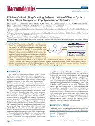
<strong>Microwave</strong>-<strong>Assisted</strong> <strong>Fabrication</strong> <strong>of</strong> <strong>Carbon</strong><br />
<strong>Nanotube</strong> <strong>AFM</strong> <strong>Tips</strong><br />
Tamara S. Druzhinina, † Stephanie Hoeppener* ,†,‡,§ and Ulrich S. Schubert* ,†,‡,§<br />
† Laboratory <strong>of</strong> Macromolecular Chemistry and Nanoscience, Eindhoven University <strong>of</strong> Technology, Den Dolech 2,<br />
5600 MB Eindhoven, The Netherlands, ‡ Dutch Polymer Institute, P.O. Box 902, 5600 AX Eindhoven,<br />
The Netherlands, and § Laboratory <strong>of</strong> Organic and Macromolecular Chemistry (IOMC), Friedrich-Schiller-University<br />
Jena, Humboldtstrasse 10, D-07743 Jena, Germany<br />
ABSTRACT A new, fast, alternative approach for the fabrication <strong>of</strong> carbon nanotube (CNT) atomic force microscopy (<strong>AFM</strong>) tips is<br />
reported. Thereby, the tube material is grown on the apex <strong>of</strong> an <strong>AFM</strong> tip by utilizing microwave irradiation and selective heating <strong>of</strong><br />
the catalyst. Reaction times as short as three minutes allowed the fabrication <strong>of</strong> CNT <strong>AFM</strong> tips in a highly efficient process. This<br />
method represents a promising approach toward a cheaper, faster, and straightforward synthesis <strong>of</strong> CNT <strong>AFM</strong> tips.<br />
KEYWORDS <strong>Carbon</strong> nanotubes, microwave, <strong>AFM</strong> tip, carbon nanotube synthesis, catalyst<br />
Scanning force microscopy has developed into a standard<br />
tool in material research and represents a frequently<br />
used technique in nearly all fields <strong>of</strong> science,<br />
including, e.g., chemistry, physics, biology, and others. 1-4<br />
The resolution <strong>of</strong> this technique is, however, strongly related<br />
to the quality <strong>of</strong> the available tip material, which limits not<br />
only the lateral resolution but also implies limitations with<br />
respect to the investigation <strong>of</strong>, e.g., steep edges. 5,6 While<br />
commercially available atomic force microscopy (<strong>AFM</strong>) tips<br />
are fabricated by using silicon micr<strong>of</strong>abrication techniques<br />
reaching a typical resolution <strong>of</strong> approximately 10 nm, tailormade<br />
tip layouts have been proposed to improve the tip<br />
performance. The tip quality depends mainly on the dimensions<br />
and shape <strong>of</strong> the probe, the durability <strong>of</strong> the tip apex,<br />
and the nature <strong>of</strong> the interaction between sample and probe.<br />
In this respect, in particular, <strong>AFM</strong> tips functionalized with a<br />
carbon nanotube (CNT) have attracted considerable attention.<br />
Due to the high Young’s modulus <strong>of</strong> the CNTs and their<br />
excellent aspect ratio, 7 attempts have been made to use<br />
them as probes for <strong>AFM</strong> experiments. Not only their unique<br />
mechanical but also their chemical and electronic properties<br />
8-12 open attractive possibilities that might result in<br />
improving imaging performance 13,14 or in measuring the<br />
properties <strong>of</strong> CNTs. 15 Due to the high resolution <strong>of</strong> CNT <strong>AFM</strong><br />
tips, they can be used to image very fine structures, such as<br />
biological and molecular materials. Several studies have<br />
been performed where CNT <strong>AFM</strong> tips were used to image<br />
biological materials, such as, DNA or proteins. 16-18 Different<br />
methods have been developed either to directly grow CNTs<br />
on <strong>AFM</strong> tips 19-23 or to place CNTs on tips. 24-27 The place-<br />
*Corresponding authors. E-mail: s.hoeppener@uni-jena.de (S.H.),<br />
ulrich.schubert@uni-jena.de (U.S.S.). Telephone: +49 (0)3641 948261<br />
(S.H.), +49 (0)3641 948202 (U.S.S.).<br />
Received for review: 06/1/2010<br />
Published on Web: 09/24/2010<br />
pubs.acs.org/NanoLett<br />
ment <strong>of</strong> the CNT on the <strong>AFM</strong> tip is usually performed by<br />
using scanning electron microscope (SEM) manipulators,<br />
where individual tubes are picked and stabilized on the <strong>AFM</strong><br />
tip with locally deposited carbon. This process is timeconsuming<br />
and requires a rather expensive experimental<br />
infrastructure and is also difficult to be used for a scale-up<br />
<strong>of</strong> the manufacturing process. Alternatively, the direct growth<br />
<strong>of</strong> CNTs onto <strong>AFM</strong> tips can be used. For this purpose<br />
different methods can be utilized, e.g., surface or pore<br />
growth. In particular the chemical vapor deposition (CVD)<br />
is frequently used and yields thin CNTs grown directly on<br />
the tip apex. Besides a relatively fast production time, still<br />
dedicated equipment as well as rather harsh reaction conditions<br />
are required using these conventional CVD approaches.<br />
Due to the fact that all these methods are time-consuming<br />
and costly, there is a demand for alternative methods for<br />
the formation <strong>of</strong> <strong>AFM</strong> CNT-tips, which makes them affordable<br />
and allows their use not only for very specialized<br />
applications.<br />
Here we introduce an alternative approach that allows the<br />
fabrication <strong>of</strong> carbon nanotube <strong>AFM</strong> probes utilizing the<br />
microwave-assisted growth <strong>of</strong> CNTs directly on the apex <strong>of</strong><br />
a commercially available <strong>AFM</strong> tip. This approach benefits<br />
from the selective heating <strong>of</strong> tip mounted catalyst particles<br />
due to a preferential absorption <strong>of</strong> the microwave irradiation,<br />
which results in a strong, local increase <strong>of</strong> the temperature<br />
that is sufficient to grow multiwall carbon nanotubes<br />
in the presence <strong>of</strong> ethanol vapor within very short time<br />
scales <strong>of</strong> a few minutes only. Different aspects <strong>of</strong> the<br />
fabrication process are discussed, and an optimized procedure<br />
to fabricate CNT tips is presented.<br />
The microwave-assisted synthesis <strong>of</strong> CNTs on <strong>AFM</strong> tips<br />
was performed according to a previously reported method. 30<br />
For the microwave irradiation in a synthetic laboratory single<br />
mode microwave (Emrys Liberator, Biotage) was used.<br />
© 2010 American Chemical Society 4009 DOI: 10.1021/nl101934j | Nano Lett. 2010, 10, 4009–4012
SCHEME 1. Experimental Setup a<br />
a Quartz glass pressure vial with mounted <strong>AFM</strong> cantilevers, support, and liquid ethanol reservoir. <strong>Microwave</strong> cavity <strong>of</strong> the single mode synthetic<br />
microwave. The pressure vial is transferred to the cavity, and microwave irradiation is applied.<br />
Typical irradiation times <strong>of</strong> 5 min were applied. 31 The<br />
reactions were performed in capped pressure vials which<br />
were loaded with 5 mL <strong>of</strong> ethanol. The samples were placed<br />
onto a quartz glass support above the liquid level <strong>of</strong> the<br />
ethanol (Scheme 1).<br />
The setup permits the use <strong>of</strong> a liquid ethanol reservoir as<br />
the carbon source in the bottom <strong>of</strong> the vial and a glass<br />
support that affords the placement <strong>of</strong> the substrate above<br />
the liquid level. This approach was demonstrated to allow<br />
the synthesis <strong>of</strong> carbon nanotubes under relatively mild<br />
synthetic conditions in rather short time scales <strong>of</strong> less than<br />
five minutes. To use this approach also to grow CNTs directly<br />
on an <strong>AFM</strong> tip, a few critical issues had to be addressed. In<br />
particular the question if the conditions to initiate the growth<br />
<strong>of</strong> CNTs onto the small area <strong>of</strong> the <strong>AFM</strong> tip can be matched<br />
had to be investigated.<br />
In the previously reported experiments it was essential<br />
for the successful growth <strong>of</strong> CNTs onto substrates that a<br />
sufficiently high pressure was generated in the vial, due to<br />
the evaporation <strong>of</strong> the carbon source, i.e., ethanol.<br />
To obtain the required synthesis conditions the total<br />
power <strong>of</strong> the microwave was limited to 200 W in the course<br />
<strong>of</strong> the experiments. Due to the restriction <strong>of</strong> the maximum<br />
temperature (250 °C) and pressure (21 bar) that can be<br />
generated within the pressure vials, the microwave irradiation<br />
usually stops automatically due to a safety shut down<br />
<strong>of</strong> the microwave. As a consequence the experimental<br />
conditions had to be adjusted to these limitations. Moreover,<br />
heat dissipation effects had to be taken into consideration.<br />
Therefore, commercially available <strong>AFM</strong> tips were mounted<br />
onto small pieces (0.5 × 1 cm) <strong>of</strong> silicon wafer by means <strong>of</strong><br />
a conducting silver paste which was used to glue the chip,<br />
to which the cantilevers and the tips are connected, onto the<br />
substrate. This allowed the control <strong>of</strong> the heat dissipation<br />
from the relatively small area <strong>of</strong> the tip material itself and,<br />
moreover, permited the convenient handling <strong>of</strong> the tips.<br />
FIGURE 1. SEM micrographs <strong>of</strong> the <strong>AFM</strong> tip before (a) and after<br />
microwave irradiation (b). The whole <strong>AFM</strong> tip is covered with nickel<br />
acetate catalyst (a) and CNTs after microwave irradiation (b).<br />
In a first experiment, commercially available <strong>AFM</strong> tips<br />
were just immersed intoa5mMethanoic solution <strong>of</strong> nickel<br />
acetate (Sigma Aldrich) dissolved in ethanol. Subsequently,<br />
the solvent was allowed to dry, and the <strong>AFM</strong> tips were<br />
mounted onto the silicon support. Scanning electron microscopy<br />
(SEM) investigations (Quanta 3D FEG, FEI, The<br />
Netherlands) prior to the microwave irradiation revealed that<br />
the catalyst material was homogenously deposited on the<br />
whole tip area (Figure 1a) as indicated by the flake-like<br />
structures on the <strong>AFM</strong> tip. This nickel acetate covering was<br />
transformed into nickel catalyst particles in the course <strong>of</strong> the<br />
microwave irradiation by thermal activation, and the individually<br />
formed particles were used as catalyst particles for<br />
the growth <strong>of</strong> CNTs. Figure 1b depicts a SEM image that was<br />
recorded after the microwave irradiation process, and it is<br />
observed that a homogeneous coating <strong>of</strong> the tip with CNTs<br />
was obtained. Thus, it could be confirmed that the chosen<br />
irradiation conditions were sufficient to obtain the required<br />
temperature and pressure conditions to form CNTs also on<br />
the <strong>AFM</strong> tip.<br />
In the next step the optimization <strong>of</strong> the catalyst deposition<br />
process was addressed to ultimately be able to grow only<br />
individual CNTs on an <strong>AFM</strong> tip. For this purpose, different<br />
approaches were tested to limit the amount <strong>of</strong> catalyst<br />
deposition. It was found that this can be achieved best by<br />
© 2010 American Chemical Society 4010 DOI: 10.1021/nl101934j | Nano Lett. 2010, 10, 4009-–4012
FIGURE 2. SEM micrographs <strong>of</strong> an <strong>AFM</strong>-tip before (a) and after<br />
microwave irradiation (b).<br />
simple scanning <strong>of</strong> the tip over a dried solution <strong>of</strong> nickel<br />
acetate drop casted onto a silicon substrate at higher contact<br />
forces (NTegra Aura <strong>AFM</strong>, NT-MDT, Russia). In this case a<br />
lower amount <strong>of</strong> nickel acetate is deposited onto the tip,<br />
which can provide the catalyst seed for the CNT growth.<br />
Figure 2a depicts the deposited material present on the <strong>AFM</strong><br />
tip after scanning a small area on the nickel acetate loaded<br />
substrate. The presence <strong>of</strong> material is very visible at the slope<br />
<strong>of</strong> the tip, indicating that small amounts <strong>of</strong> the nickel acetate<br />
were attached to the tip. The prepared tips were subsequently<br />
mounted in the microwave vials, and the CNT<br />
growth was pursued.<br />
Figure 2b shows the conversion <strong>of</strong> the nickel acetate<br />
material into the catalyst particles, which are observed both<br />
on the tip apex as well as on the slope <strong>of</strong> the tip itself. It could<br />
be observed that few CNTs are grown from the tip, and in<br />
particular, one CNT protrudes vertically away from the tip.<br />
This CNT has a length <strong>of</strong> approximately 600 nm and a<br />
diameter <strong>of</strong> 20 nm. Due to the length, a bending <strong>of</strong> the CNT<br />
is observed. 28,29 This result demonstrates that it is possible<br />
to obtain reaction conditions within the pressure vial that<br />
permit the growth <strong>of</strong> individual CNTs due to an effective<br />
compensation <strong>of</strong> the heat dissipation effects. In previous<br />
experiments, performed to grow individual CNTs onto solid<br />
substrates, it was observed that this represents a challenging<br />
task, which was up to now not sufficiently implemented into<br />
the surface-based synthesis approach. However, still the<br />
amount <strong>of</strong> catalyst material attached to the tip is not yet well<br />
controlled due to the fact that the <strong>AFM</strong> tip collects considerable<br />
amounts <strong>of</strong> nickel acetate during the scanning process<br />
<strong>of</strong> the dried layer.<br />
<strong>AFM</strong> force spectroscopy was conducted to further demonstrate<br />
the successful functionalization <strong>of</strong> the <strong>AFM</strong> tips with<br />
carbon nanotubes. Therefore, a set <strong>of</strong> measurements was<br />
performed that included first the recording <strong>of</strong> an approach<br />
and retraction curve with a CNT-modified <strong>AFM</strong> tip in the<br />
static <strong>AFM</strong> mode.<br />
Figure 3a displays a representative curve that clearly<br />
demonstrates the bending <strong>of</strong> the cantilever away from the<br />
surface, when the CNTs are in contact with the surface and<br />
start to slide away or buckle. Relatively large adhesion forces<br />
suggest in this case that several CNTs are attached to the<br />
cantilever, which have a length <strong>of</strong> approximately 60 nm, as<br />
estimated from the z-displacement position <strong>of</strong> the onset <strong>of</strong><br />
the bending curve until the typical proportional deflection<br />
<strong>of</strong> the cantilever is observed. These curves are reproducible<br />
FIGURE 3. Force spectroscopy <strong>of</strong> CNT functionalized <strong>AFM</strong> tips. (a)<br />
Representative deflection vs distance plot <strong>of</strong> a CNT modified tip. (b)<br />
Measurement with the same tip after the CNT material was removed<br />
by appling higher forces. (c) I-V curve <strong>of</strong> a CNT-modified tip gently<br />
approached onto the substrate.<br />
© 2010 American Chemical Society 4011 DOI: 10.1021/nl101934j | Nano Lett. 2010, 10, 4009-–4012
indicating the stability <strong>of</strong> the CNTs onto the tip. After this<br />
significantly higher forces were applied onto the tip to<br />
remove the CNT material on purpose. The force spectroscopic<br />
measurements after this process (Figure 3b) indicate<br />
the characteristic deviation <strong>of</strong> the deflection vs distance<br />
curves, and a significant decrease <strong>of</strong> the adhesion forces was<br />
observed. Moreover, the characteristic snap-in points are<br />
clearly visible, without any indication for a bending <strong>of</strong> the<br />
cantilever prior to the contact <strong>of</strong> the <strong>AFM</strong> tip.<br />
Additionally, the current-voltage characteristic (Figure<br />
3c) was measured on a CNT-modified metal-coated <strong>AFM</strong> that<br />
was gently brought into contact with a graphite substrate.<br />
In this case a small significantly reduced conductivity could<br />
be measured compared to nonmodified metal-coated tips.<br />
In conclusion, a powerful process was developed that<br />
allows the direct fabrication <strong>of</strong> CNT <strong>AFM</strong> tips utilizing<br />
efficient synthetic conditions generated in a single mode<br />
microwave reactor. It could be demonstrated that the growth<br />
<strong>of</strong> individual CNTs can be achieved, and the optimization <strong>of</strong><br />
the preparation conditions resulted in a promising approach<br />
that enabled the fabrication <strong>of</strong> CNT <strong>AFM</strong> tips utilizing<br />
relatively mild synthesis conditions.<br />
In particular the relatively low experimental affords as<br />
well as the fast fabrication times are a general advantage <strong>of</strong><br />
the introduced method and provide a promising, cheap<br />
technique to fabricate CNT <strong>AFM</strong> tips. The deposition <strong>of</strong> the<br />
catalyst material could be further improved by utilizing<br />
particle picking approaches, e.g., by force vs distance curve<br />
recording, to further increase the controllability <strong>of</strong> the<br />
presented approach.<br />
Acknowledgment. The authors are grateful for the financial<br />
support <strong>of</strong> the Dutch Council <strong>of</strong> Scientific Research<br />
(NWO) by a VICI grant awarded to U.S.S. This research has<br />
been carried out with the support <strong>of</strong> the Materials and<br />
Interface Chemistry Research Unit (SEM) and the Department<br />
<strong>of</strong> Chemical Engineering and Chemistry, Eindhoven<br />
University <strong>of</strong> Technology. Dr. Alexander Alexeev is kindly<br />
acknowledged for help with the conductivity measurements<br />
and for fruitful discussions. We thank the Dutch Polymer<br />
Institute (DPI, technology area HTE) for funding.<br />
REFERENCES AND NOTES<br />
(1) Magonov, S. N.; Qvarnström, K.; Elings, V.; Cantow, H. J. Polym.<br />
Bull. 1991, 25, 689–694.<br />
(2) Radmacher, M.; Tillamnn, R. W.; Fritz, W.; Gaub, H. E. Science<br />
1992, 257, 1900–1905.<br />
(3) Binning, G.; Rohrer, H.; Gerber, Ch.; Weibel, E. Phys. Rev. Lett.<br />
1982, 49, 57–61.<br />
(4) Zhong, Q.; Inniss, D.; Kjoller, K.; Elings, V. B. Surf. Sci. 1993, 290,<br />
L688–692.<br />
(5) Murayama, K.; Gonda, S.; Koyanagi, H.; Terasawa, T.; Hosaka,<br />
S. Jpn. J. Appl. Phys. 2006, 45, 5928–5932.<br />
(6) Morimoto, T.; Kuroda, H.; Minomoto, Y.; Nagano, Y.; Kembo, Y.;<br />
Hosaka, S. Jpn. J. Appl. Phys. 2002, 41, 4238–4241.<br />
(7) Xu, D. H.; Wang, Z.-G.; Douglas, J. F. Macromolecules 2008, 41,<br />
815–825.<br />
(8) Wong, S.; Harper, J.; Lansbury, P.; Lieber, C. J. Am. Chem. Soc.<br />
1998, 120, 603–604.<br />
(9) Dai, H.; Franklin, N.; Han, J. Appl. Phys. Lett. 1998, 73, 1508–<br />
1510.<br />
(10) Wong, S.; Wooley, A.; Joselevich, E.; Lieber, C. Chem. Phys. Lett.<br />
1999, 306, 219–225.<br />
(11) Wong, S.; Woolley, A.; Joselevich, E.; Cheung, C.; Lieber, C. J. Am.<br />
Chem. Soc. 1998, 120, 8557–8558.<br />
(12) Wong, E. W.; Sheehan, P. E.; Lieber, C. M. Science 1997, 277,<br />
1971–1975.<br />
(13) Cooper, E. B.; Manalis, S. R.; Fang, H.; Dai, H.; Matsumoto, K.;<br />
Minne, S. C.; Hunt, T.; Quate, C. F. Appl. Phys. Lett. 1999, 75,<br />
3566–3568.<br />
(14) Krause, O.; Bouchiat, V.; Bonnot, A. M. J. Phys.: Conf. Ser. 2001,<br />
61, 628–632.<br />
(15) Barber, A. H.; Andrews, R.; Schadler, L. S.; Wagner, H. D. Appl.<br />
Phys. Lett. 2005, 87, 203106-1203106-3.<br />
(16) Hafner, J. H.; Cheung, C.-L.; Woolley, A. T.; Lieber, C. M. Prog.<br />
Biophys. Mol. Biol. 2001, 77, 73–110.<br />
(17) Nishijima, H.; Kamo, S.; Akita, S.; Nakayama, Y.; Hohmura, K. I.;<br />
Yoshimura, S. H.; Takeyasu, K. Appl. Phys. Lett. 1999, 74, 4061–<br />
4063.<br />
(18) Bunch, J. S.; Rhodin, T. N.; McEuen, P. L. Nanotechnology 2004,<br />
15, S76–S78.<br />
(19) Hafner, J.; Cheung, C.; Lieber, C. Nature 1999, 398, 761–762.<br />
(20) Hafner, J.; Cheung, C.; Lieber, C. M. J. Am. Chem. Soc. 1999, 121,<br />
9750–9751.<br />
(21) Stevens, R.; Nguyen, C.; Cassell, A.; Delzeit, L.; Meyyappan, M.;<br />
Han, J. Appl. Phys. Lett. 2000, 77, 3453–3455.<br />
(22) Cheung, C. L.; Hafner, J. H.; Lieber, C. M. Proc. Natl. Acad. Sci.<br />
U.S.A. 2000, 97, 3809–3813.<br />
(23) Cheung, C. L.; Hafner, J. H.; Odom, T. W.; Kim, K.; Lieber, C. M.<br />
Appl. Phys. Lett. 2000, 76, 3136–3138.<br />
(24) Akita, S.; Nishijima, H.; Nakayama, Y.; Tokumasu, F.; Takeyasu,<br />
K. J. Phys. D: Appl. Phys. 1999, 32, 1044–1048.<br />
(25) Hafner, J. H.; Cheung, C.-L.; Oosterkamp, T. H.; Lieber, C. M. J.<br />
Phys. Chem. B 2001, 105, 743–746.<br />
(26) Hall, A.; Matthews, W. G.; Superfine, R.; Falvo, M. R.; Washburn,<br />
S. Appl. Phys. Lett. 2003, 82, 2506–2508.<br />
(27) Chin, S.-C.; Chang, Y.-C.; Chang, C.-S. Nanotechnology 2009, 20,<br />
2853071–2853079.<br />
(28) Falvo, M. R.; Clary, G. J.; Taylor, R. M.; Brooks, F. P.; Washburn,<br />
S.; Superfine, R. Nature 1997, 389, 582–584.<br />
(29) Martinez, J.; Yuzvinsky, T. D.; Fennimore, A. M.; Zettl, A.; García,<br />
R.; Bustamante, C. Nanotechnology 2005, 16, 2493–2496.<br />
(30) Druzhinina, T. S.; Weltjens, W.; Hoeppener, S.; Schubert, U. S.<br />
Adv. Funct. Mater. 2009, 19, 1287–1292.<br />
(31) Druzhinina, T. S.; Hoeppener, S.; Schubert, U. S. Adv. Funct. Mater.<br />
2009, 19, 2819–2825.<br />
© 2010 American Chemical Society 4012 DOI: 10.1021/nl101934j | Nano Lett. 2010, 10, 4009-–4012