Technical Reference Guide|Rev F HomeWorks® - Lutron
Technical Reference Guide|Rev F HomeWorks® - Lutron
Technical Reference Guide|Rev F HomeWorks® - Lutron

Create successful ePaper yourself
Turn your PDF publications into a flip-book with our unique Google optimized e-Paper software.
<strong>HomeWorks®</strong><br />
<strong>Technical</strong> <strong>Reference</strong> Guide| Rev F
Table of Contents<br />
Introduction<br />
Introduction to <strong>HomeWorks®</strong> . . . . . . . . . . . . . . . . . . 4<br />
Features Overview . . . . . . . . . . . . . . . . . . . . . . . . . 6<br />
Specifying a HomeWorks System . . . . . . . . . . . . . . . . 8<br />
Construction Type . . . . . . . . . . . . . . . . . . . . . . . . 9<br />
System Design . . . . . . . . . . . . . . . . . . . . . . . . . 10<br />
Aesthetic Styles . . . . . . . . . . . . . . . . . . . . . . . . 11<br />
System Design<br />
New Construction or Major Renovation . . . . . . . . . . . 14<br />
Localized Design . . . . . . . . . . . . . . . . . . . . . . . . 15<br />
Centralized Design . . . . . . . . . . . . . . . . . . . . . . . 16<br />
Optimized Design . . . . . . . . . . . . . . . . . . . . . . . 17<br />
New Construction System Design Overview . . . . . . 18<br />
System Wiring and Communication Overview . . . . . 20<br />
Existing Construction or Minor Renovation . . . . . . . . 22<br />
Localized Design . . . . . . . . . . . . . . . . . . . . . . . . 23<br />
Existing Construction System Design Overview . . . . 24<br />
RF Coverage Diagram . . . . . . . . . . . . . . . . . . . . . 25<br />
System Wiring and Communication Overview . . . . . 26<br />
Component Overview<br />
Wired Processors . . . . . . . . . . . . . . . . . . . . . . . . . 30<br />
RF Processors . . . . . . . . . . . . . . . . . . . . . . . . . . . . 33<br />
RF Signal Repeater . . . . . . . . . . . . . . . . . . . . . . . . 36<br />
Module Interface . . . . . . . . . . . . . . . . . . . . . . . . . 37<br />
Remote Power Modules . . . . . . . . . . . . . . . . . . . . . 38<br />
Remote Power Feed-Through Panels . . . . . . . . . . . . . 40<br />
Remote Power Panels with Breakers . . . . . . . . . . . . . 41<br />
GRAFIK Eye ® Preset Local Lighting Controls . . . . . . . 42<br />
Wallbox Power Module . . . . . . . . . . . . . . . . . . . . . . 43<br />
D48 Dimmer Interface . . . . . . . . . . . . . . . . . . . . . . 44<br />
Wired Vareo ® Local Lighting Controls . . . . . . . . . . . . 45<br />
Component Overview (cont.)<br />
H48 Dimmer Interface . . . . . . . . . . . . . . . . . . . . . . 46<br />
Wired Maestro® Local Lighting Controls . . . . . . . . . . 47<br />
RF Maestro Local Lighting Controls . . . . . . . . . . . . . 48<br />
Power Boosters and 120V Interfaces . . . . . . . . . . . . 49<br />
Keypads . . . . . . . . . . . . . . . . . . . . . . . . . . . . . . . 50<br />
Wired Keypads . . . . . . . . . . . . . . . . . . . . . . . . . 52<br />
RF Keypads . . . . . . . . . . . . . . . . . . . . . . . . . . . 62<br />
RF Tabletop Keypads . . . . . . . . . . . . . . . . . . . . . 65<br />
RF Lamp Dimmer . . . . . . . . . . . . . . . . . . . . . . . . . 66<br />
RF Visor Controls . . . . . . . . . . . . . . . . . . . . . . . . . 67<br />
Contact Closure Interfaces . . . . . . . . . . . . . . . . . . . 68<br />
Wired Contact Closure Input Interface . . . . . . . . . 68<br />
RF Contact Closure Input Interface . . . . . . . . . . . 69<br />
Wired Contact Closure Output Interface . . . . . . . . 70<br />
Low-Voltage Enclosures . . . . . . . . . . . . . . . . . . . . . 71<br />
32" Low-Voltage Enclosure . . . . . . . . . . . . . . . . . 71<br />
Contact Closure Interface Subplate . . . . . . . . . . . 71<br />
17" Low-Voltage Enclosure . . . . . . . . . . . . . . . . . 72<br />
10" Low-Voltage Enclosure . . . . . . . . . . . . . . . . . 72<br />
Wire Landing Board . . . . . . . . . . . . . . . . . . . . . . . 73<br />
Telephone Interface . . . . . . . . . . . . . . . . . . . . . . . 74<br />
Auxiliary Power Supply . . . . . . . . . . . . . . . . . . . . . 75<br />
Handheld Programmer and Jack . . . . . . . . . . . . . . . 76<br />
Architectural-style Coordinating Accessories . . . . . . . 78<br />
Designer-style Coordinating Accessories . . . . . . . . . . 80<br />
<strong>Technical</strong> Specifications<br />
System Specifications . . . . . . . . . . . . . . . . . . . . . . 84<br />
Wired Processors . . . . . . . . . . . . . . . . . . . . . . . . . 86<br />
RF Processors . . . . . . . . . . . . . . . . . . . . . . . . . . . . 88<br />
RF Signal Repeater . . . . . . . . . . . . . . . . . . . . . . . . 90<br />
Module Interface . . . . . . . . . . . . . . . . . . . . . . . . . 92<br />
c2 <strong>Technical</strong> Support • 24 Hours a Day/7 Days a Week • 1.800.523.9466
Table of Contents (cont.)<br />
<strong>Technical</strong> Specifications (cont.)<br />
Remote Power Modules . . . . . . . . . . . . . . . . . . . . . 94<br />
Remote Power Feed-Through Panels . . . . . . . . . . . . . 98<br />
HWI-PNL-8 . . . . . . . . . . . . . . . . . . . . . . . . . . . . 98<br />
HWI-PNL-5 . . . . . . . . . . . . . . . . . . . . . . . . . . . 100<br />
Remote Power Panels with Breakers . . . . . . . . . . . . 102<br />
HWBP-8D . . . . . . . . . . . . . . . . . . . . . . . . . . . . 102<br />
HWBP-2S . . . . . . . . . . . . . . . . . . . . . . . . . . . . 104<br />
GRAFIK Eye ® Preset Local Lighting Controls . . . . . . . 106<br />
Wallbox Power Module . . . . . . . . . . . . . . . . . . . . . 110<br />
D48 Dimmer Interface . . . . . . . . . . . . . . . . . . . . . 113<br />
Wired Vareo ® Local Lighting Controls . . . . . . . . . . . 115<br />
H48 Dimmer Interface . . . . . . . . . . . . . . . . . . . . . 123<br />
Wired Maestro ® Local Lighting Controls . . . . . . . . . . 125<br />
RF Maestro Local Lighting Controls . . . . . . . . . . . . 132<br />
Power Boosters and 120V Interfaces . . . . . . . . . . . 138<br />
Wired Keypads . . . . . . . . . . . . . . . . . . . . . . . . . . 146<br />
RF Keypads . . . . . . . . . . . . . . . . . . . . . . . . . . . . 149<br />
RF Tabletop Keypads . . . . . . . . . . . . . . . . . . . . . . 150<br />
RF Lamp Dimmer . . . . . . . . . . . . . . . . . . . . . . . . . 151<br />
RF Visor Controls . . . . . . . . . . . . . . . . . . . . . . . . 152<br />
Contact Closure Interfaces . . . . . . . . . . . . . . . . . . 153<br />
Wired Contact Closure Input Interface . . . . . . . . 153<br />
RF Contact Closure Input Interface . . . . . . . . . . . 155<br />
Wired Contact Closure Output Interface . . . . . . . 157<br />
Low-Voltage Enclosures . . . . . . . . . . . . . . . . . . . . 159<br />
32" Low-Voltage Enclosure . . . . . . . . . . . . . . . . 159<br />
Contact Closure Interface Subplate . . . . . . . . . . . 161<br />
17" Low-Voltage Enclosure . . . . . . . . . . . . . . . . 162<br />
10" Low-Voltage Enclosure . . . . . . . . . . . . . . . . 164<br />
Wire Landing Board . . . . . . . . . . . . . . . . . . . . . . . 165<br />
Telephone Interface . . . . . . . . . . . . . . . . . . . . . . 166<br />
Auxiliary Power Supply . . . . . . . . . . . . . . . . . . . . 168<br />
<strong>Technical</strong> Specifications (cont.)<br />
Link Extender . . . . . . . . . . . . . . . . . . . . . . . . . . . 169<br />
Filter Choke . . . . . . . . . . . . . . . . . . . . . . . . . . . . 171<br />
Handheld Programmer and Accessories . . . . . . . . . . 172<br />
Patent and Trademark Information . . . . . . . . . . . . . 174<br />
Short Form Performance Specifications & Benefits<br />
We continue to update our products to serve your needs<br />
better. Please see our web site for the most up-to-date<br />
version. www.lutron.com/hwi<br />
www.lutron.com <strong>Technical</strong> Support: product@lutron.com<br />
3
INTRODUCTION COMPONENTS PRE-WIRING<br />
Introduction to <strong>HomeWorks®</strong><br />
The Most Powerful and Most Flexible<br />
Lighting Control System in the World<br />
Whether building a new home, renovating an existing one<br />
or updating current lighting controls, HomeWorks provides<br />
the perfect control solution. HomeWorks, the world’s leading<br />
whole-house lighting control system, provides simple,<br />
convenient control of all home lighting, as well as the<br />
ability to control audio, video, and many other subsystems<br />
in a home. HomeWorks provides many benefits<br />
including:<br />
• Increased Security<br />
• Design and Control Flexibility<br />
• Added Convenience<br />
• Improved Aesthetics<br />
INCREASED SECURITY<br />
HomeWorks seamlessly integrates with home security systems.<br />
In the event of an alarm, interior lights turn on,<br />
illuminating a safe exit, while exterior lights flash, thereby<br />
drawing immediate attention.<br />
HomeWorks provides peace of mind by allowing homeowners<br />
the ability to turn all lights on instantly from a single<br />
button press.<br />
HomeWorks makes a home safer by automatically turning<br />
on landscape and security lighting each night. A built-in<br />
astronomical timeclock automatically adjusts for changing<br />
sunrise and sunset times throughout the year.<br />
Every day, a HomeWorks system automatically records the<br />
home’s actual lighting usage patterns. These patterns are<br />
replayed when the home is unoccupied. This unique feature<br />
allows for a realistic appearance of activity that standard<br />
timers cannot achieve.<br />
DESIGN AND CONTROL FLEXIBILITY<br />
HomeWorks systems provide the ultimate flexibility. Wired<br />
control products are targeted for new home construction,<br />
and radio frequency (RF) control products for retrofit<br />
installations. Use a combination of both products, wired<br />
and RF, when undergoing minor renovations or when<br />
building an addition onto an existing residence.<br />
When designing a control system that is not part of the<br />
original specification, or expanding an existing system,<br />
RF products provide an easy retrofit solution. RF products<br />
allow the system to be expanded at any time, accommodating<br />
unexpected additions and last minute changes.<br />
After the installation, homeowners still retain a high level<br />
of flexibility. seeTouchTM Keypads may be easily reconfigured<br />
to accommodate new control requirements. To change<br />
color, engraving, and button configuration, simply snap<br />
off the existing seeTouch button faceplate kit and replace<br />
it with a new one.<br />
ADDED CONVENIENCE<br />
Control each light in a home from any HomeWorks Keypad,<br />
providing instant access to all areas of the home and<br />
landscape. This eliminates the tedious task of setting the<br />
home lighting just right for daily activities or special<br />
occasions.<br />
A single button press creates a “path of light” to softly<br />
light the way to another room, allowing for late-night<br />
trips to the bathroom or kitchen without fumbling for<br />
switches in a dark hallway. Monitoring individual rooms or<br />
areas throughout a home requires no more than a quick<br />
glance at a keypad’s discreet status LEDs.<br />
4 <strong>Technical</strong> Support • 24 Hours a Day/7 Days a Week • 1.800.523.9466
Introduction to <strong>HomeWorks®</strong> (cont.)<br />
IMPROVED AESTHETICS<br />
HomeWorks gives homeowners the power to enhance the<br />
beauty of their home and decor with an endless variety<br />
of customized room and whole-house lighting scenes.<br />
One button press dims the lights for a soft romantic<br />
dinner while another button press lights the house for<br />
a festive party.<br />
Keypads provide a clean, elegant look on the wall by combining<br />
the functions of many standard switches and dimmers<br />
into a single control. Contrast the elegant simplicity<br />
of a single keypad to the large bank of switches often<br />
found at the front door. Integrate whole-house audio and<br />
video controls into HomeWorks Keypads to further reduce<br />
wall clutter and provide a consistent look.<br />
Integrate wall controls from most other systems in a home<br />
under one seamless, customized wallplate to maintain<br />
aesthetic consistency. Match keypads to a home’s paint,<br />
wallpaper or decor.<br />
<strong>Lutron</strong> combines the industry’s largest selection of controls<br />
and matching accessories with an extensive array<br />
of colors and finishes. HomeWorks Keypads are available<br />
with custom engraving. seeTouchTM Keypads provide a<br />
unique backlighting feature whereby engraving is readable<br />
in the dark.<br />
Replace large banks of switches with<br />
one elegant keypad<br />
www.lutron.com <strong>Technical</strong> Support: product@lutron.com<br />
5<br />
INTRODUCTION COMPONENTS PRE-WIRING
INTRODUCTION COMPONENTS PRE-WIRING<br />
Features Overview<br />
LUTRON QUALITY<br />
<strong>Lutron</strong> has been the world leader in lighting controls since<br />
inventing the solid-state dimmer more than 40 years ago.<br />
All <strong>Lutron</strong>® products are designed and manufactured to<br />
the highest quality standards, minimizing the likelihood<br />
of damage caused by power surges, lightning strikes, or<br />
static electricity. All <strong>HomeWorks®</strong> systems are covered by<br />
an 8-year limited warranty. <strong>Lutron</strong> was one of the first 20<br />
companies in the US to earn the ISO 9001 international<br />
quality certification. <strong>Lutron</strong> is ISO 9001:2000 certified.<br />
F AIL-SAFE OPERATION<br />
HomeWorks Local Lighting Controls and GRAFIK Eye®<br />
Preset Local Lighting Controls remain fully functional even<br />
in the unlikely event communication to the processor is<br />
interrupted. Dimming panels also have manual override<br />
capabilities, which can be activated from dedicated<br />
switches located anywhere in the home.<br />
POWER-FAILURE MEMORY<br />
All HomeWorks components are designed with 10-year<br />
power-failure memory. If power is interrupted and<br />
restored, lights will automatically return to the levels to<br />
which they were set prior to the power outage. HomeWorks<br />
system programming is retained in non-volatile memory<br />
and is not affected by loss of power.<br />
SECURITY<br />
Connect HomeWorks to a security system to activate lights<br />
in case of an alarm. Selected lights will turn on to a predetermined<br />
security level, while others flash repeatedly to<br />
attract attention. Security Mode may also be activated<br />
manually from a keypad. When Security Mode is deactivated,<br />
the lighting returns to the original levels set before<br />
Security Mode was activated.<br />
AESTHETIC CONSISTENCY<br />
HomeWorks Keypads and Local Lighting Controls complement<br />
each other with matching colors, styles, and finishes.<br />
A full range of wallplates, receptacles, telephone jacks,<br />
and cable jacks are available to match the system controls.<br />
Architectural-style faceplates can also be customized<br />
to match a home’s paint, wallcoverings, or decor.<br />
ASTRONOMICAL TIMECLOCK<br />
HomeWorks can automatically trigger events at specific<br />
times of the day or at times relative to sunrise or sunset.<br />
Program multiple schedules allowing for different timeclock<br />
events on weekdays, weekends, holidays, etc. Enable or<br />
disable timeclock schedules from any keypad. Additionally,<br />
any timeclock event can be programmed using conditional<br />
logic, so the event will occur only if a specified condition<br />
is met.<br />
TELEPHONE INTERFA CE<br />
The Telephone Interface allows the homeowner to access<br />
and control up to ten different functions or events from<br />
any touchtone phone. The Telephone Interface guides the<br />
homeowner through each step with customized voice messages<br />
and provides positive verbal response when a function<br />
or event has been activated. Utilize this capability<br />
from telephones within the house or across the world.<br />
VA CATION MODE<br />
HomeWorks constantly monitors and records the state of<br />
all lighting in a home. When Vacation Mode is activated,<br />
the system plays back these events, providing a realistic<br />
appearance of activity while the home is unoccupied. The<br />
system can be programmed to record the last day’s, the<br />
last week’s, or the last two weeks’ activities.<br />
6 <strong>Technical</strong> Support • 24 Hours a Day/7 Days a Week • 1.800.523.9466
Features Overview (cont.)<br />
INTEGRATION<br />
HomeWorks ® has been designed to integrate with audio,<br />
video, and other subsystems in a home. A typical application<br />
includes control of an audio system from buttons on<br />
a HomeWorks Keypad. Interface the system with other<br />
equipment using contact closure inputs and outputs,<br />
infrared inputs, and RS-232 serial communication.<br />
CONDITIONAL LOGIC<br />
HomeWorks provides the capability to activate events only<br />
if specific conditions are met. For example, program<br />
driveway sensors to turn on exterior lighting only if it is<br />
dark. A single “Dining” button could set different lighting<br />
and music for breakfast, lunch, and dinner.<br />
RETROFIT WITH EASE<br />
Add lighting control to existing homes with HomeWorks<br />
RF devices. Existing switches are replaced with RF Dimmers,<br />
RF Switches, and RF Keypads using existing line-voltage<br />
wiring. RF Lamp Dimmers simply plug into receptacles to<br />
integrate table and floor lamps into the system.<br />
PROGRAMMING FLEXIBILITY<br />
HomeWorks Keypads can be customized to meet customers’<br />
changing needs. Each keypad button may be programmed<br />
to activate any of the lights in the system. Keypad buttons<br />
may also be programmed to control audio, video, and<br />
other integrated subsystems.<br />
B A CKLIT KEYPADS<br />
HomeWorks seeTouchTM Keypads are backlit so that the button<br />
labels are easily read in a dark room.<br />
RF TABLETOP CONTROLS<br />
HomeWorks RF Tabletop Keypads and RF Lamp Dimmers offer<br />
great flexibility for the placement of controls. Locations<br />
such as bedside, countertops, and end tables are ideal for<br />
these controls.<br />
CAR VISOR CONTROL<br />
The HomeWorks Car Visor transmitter clips on to a car’s<br />
sun visor providing complete control of the system from<br />
the convenience of the car. Any car equipped with<br />
is compatible as well.<br />
HomeLink and the HomeLink Compatible logo are registered trademarks<br />
of Johnson Controls.<br />
www.lutron.com <strong>Technical</strong> Support: product@lutron.com<br />
7<br />
INTRODUCTION COMPONENTS PRE-WIRING
INTRODUCTION COMPONENTS PRE-WIRING<br />
Specifying a <strong>HomeWorks®</strong> System<br />
There are three key elements to specifying a HomeWorks system:<br />
• Establish Construction Type<br />
• Choose System Design<br />
• Select Aesthetic Style<br />
A system designer must understand these three elements and their customers’ requirements to select the proper system<br />
components.<br />
Construction Types System Designs Aesthetic Styles<br />
New Construction<br />
Existing Construction<br />
• Localized<br />
• Centralized<br />
• Optimized<br />
• Architectural<br />
• Designer<br />
• Localized • Designer<br />
8 <strong>Technical</strong> Support • 24 Hours a Day/7 Days a Week • 1.800.523.9466
Construction Type<br />
<strong>HomeWorks®</strong> can be used in both new and existing homes. A project’s construction type determines the system design<br />
options and the aesthetic style offerings.<br />
Two construction types exist:<br />
NEW CONSTRUCTION OR MAJOR RENOVATION<br />
Open wall access allows low-voltage communication wiring to be easily run to controls. This construction type<br />
provides maximum flexibility in system design (localized, centralized, optimized) and aesthetic styles (Architectural<br />
and Designer).<br />
EXISTING CONSTRUCTION OR MINOR RENOVATION<br />
Retrofit applications use RF controls, eliminating the difficult or impossible task of running low-voltage wiring. This<br />
construction type will have a localized system design and a Designer-style aesthetic.<br />
USING THIS GUIDE<br />
Page headers will indicate which products are suitable for new construction and which products are suitable for existing<br />
construction.<br />
Pages in this guide that include products suitable for new construction will have the following box highlighted:<br />
Architectural-style Designer-style New Construction Existing Construction<br />
Pages in this guide that include products suitable for existing construction will have the following box highlighted:<br />
Architectural-style Designer-style New Construction Existing Construction<br />
www.lutron.com <strong>Technical</strong> Support: product@lutron.com<br />
9<br />
INTRODUCTION COMPONENTS PRE-WIRING
INTRODUCTION COMPONENTS PRE-WIRING<br />
System Design<br />
Typical system designs begin with a floor plan layout. The system design and controls used are based on the construction<br />
type and customer requirements. <strong>HomeWorks®</strong> flexible architecture provides multiple system design options. Depending on<br />
construction type and customer preferences, HomeWorks systems may be designed in three different ways:<br />
LOCALIZED DESIGN<br />
Localized designs use a traditional approach to lighting control, placing familiar, easy-to-use dimmers throughout the<br />
home. Keypads are added to the design for control of multiple lights.<br />
CENTRALIZED DESIGN<br />
Centralized designs place dimmers remotely, eliminating local lighting controls. All lights are controlled from keypads,<br />
providing maximum programming flexibility, while minimizing wall clutter.<br />
OPTIMIZED DESIGN<br />
Optimized designs combine the benefits of localized and centralized designs. Local dimmers are placed in areas where<br />
simple, straight-forward operation is desired (guest bedrooms, bathrooms and kids’ rooms). Keypads and remotelymounted<br />
dimmers replace banks of switches in areas where multiple lights are controlled (front door, kitchen and<br />
master bedroom).<br />
Pgs. 14-27 cover these system designs in detail.<br />
10 <strong>Technical</strong> Support • 24 Hours a Day/7 Days a Week • 1.800.523.9466
Aesthetic Styles<br />
<strong>HomeWorks®</strong> products are available in two aesthetic styles:<br />
ARCHITECTURAL-STYLE<br />
Architectural-style products include Vareo® Local Lighting Controls, GRAFIK Eye® Controls, Architectural-style Keypads, and<br />
Nova TA® coordinating accessories. These products are available for new construction projects only.<br />
FEATURES<br />
• Products available with Architectural Matte plastic and metal finishes<br />
• Square corners, beveled edges<br />
• Minimalist aesthetics intended to blend with its environment<br />
• Color matching available<br />
DESIGNER-STYLE<br />
Designer-style products include Maestro® Local Lighting Controls, Designer-style Keypads, and Claro® and Satin ColorsTM<br />
coordinating accessories. These products are available for new construction and existing construction projects.<br />
FEATURES<br />
• Products available with Designer Gloss Colors and Satin Colors matte plastic finishes<br />
• Rounded corners, rounded edges<br />
• Fashion aesthetic intended to complement its environment<br />
• All products use standard decorator opening<br />
USING THIS GUIDE<br />
Pages in this guide that include Architectural-style products will have the following box highlighted:<br />
Architectural-style Designer-style New Construction Existing Construction<br />
Pages in this guide that include Designer-style products will have the following box highlighted:<br />
Architectural-style Designer-style New Construction Existing Construction<br />
www.lutron.com <strong>Technical</strong> Support: product@lutron.com<br />
11<br />
INTRODUCTION COMPONENTS PRE-WIRING
Notes:<br />
12 <strong>Technical</strong> Support • 24 Hours a Day/7 Days a Week • 1.800.523.9466
System Design<br />
www.lutron.com <strong>Technical</strong> Support: product@lutron.com<br />
13<br />
INTRODUCTION SYSTEM DESIGN COMPONENTS PRE-WIRING
INTRODUCTION SYSTEM DESIGN COMPONENTS PRE-WIRING<br />
System Design<br />
New Construction<br />
or<br />
Major Renovation<br />
14 <strong>Technical</strong> Support • 24 Hours a Day/7 Days a Week • 1.800.523.9466
Architectural-style Designer-style New Construction Existing Construction<br />
Localized Design<br />
A localized design for new construction uses HomeWorks ®<br />
Local Lighting Controls (Wired Vareo ®, and Maestro ® Local<br />
Lighting Controls, GRAFIK Eye ® Preset Local Lighting<br />
Controls, and RF Lamp Dimmers) to directly control all<br />
lighting loads. One benefit of this type of system is that<br />
it is easily understood by homeowners and guests, since<br />
the individual lighting loads are controlled in the same<br />
manner as with traditional dimmers and switches.<br />
Keypads are added to provide control of multiple lights<br />
within one area or to control all of the lights throughout<br />
the home. In this design, keypads are typically installed in<br />
locations such as entryways, master bedrooms, and key<br />
entertaining areas.<br />
Local lighting controls allow the homeowner to dim and<br />
switch loads directly, providing “fail-safe” operation, even<br />
if communication to the processor is temporarily interrupted.<br />
The addition of RF devices to a localized design provides<br />
convenient portable control from any location. Activate<br />
lights from an RF Tabletop Keypad. Dim table and floor<br />
lamps from RF Lamp Dimmers. Control garage doors and<br />
lighting from RF Visor Controls.<br />
The new construction localized design is the only true<br />
pre-wire compatible configuration for whole-home lighting<br />
control because it uses the same line-voltage wiring plan<br />
as a home without a control system. This design is ideal<br />
for the homeowner who wants to add a wired control<br />
system at any time.<br />
LOCALIZED DESIGN SUMMARY:<br />
• Simple controls, familiar operation<br />
• Local lighting controls provide “fail-safe” operation<br />
• Add portable RF devices for convenient control<br />
• Pre-wire capability<br />
• Uses existing line-voltage wiring<br />
indicates line-voltage power wiring<br />
indicates local lighting control low-voltage communication wiring<br />
indicates keypad low-voltage communication wiring<br />
indicates GRAFIK Eye low-voltage communication wiring<br />
indicates RF communication<br />
Note: wiring shown is for concept only<br />
www.lutron.com <strong>Technical</strong> Support: product@lutron.com<br />
15<br />
INTRODUCTION SYSTEM DESIGN COMPONENTS PRE-WIRING
INTRODUCTION SYSTEM DESIGN COMPONENTS PRE-WIRING<br />
Architectural-style Designer-style New Construction Existing Construction<br />
Centralized Design<br />
A centralized design for new construction uses Remote<br />
Power Modules to control all lighting loads, eliminating<br />
local lighting controls. The Remote Power Modules are<br />
mounted in Remote Power Panels, located in equipment<br />
rooms or electrical closets. In this design, all lights are<br />
controlled from keypads, providing the maximum programming<br />
flexibility while minimizing wall clutter. Keypads<br />
have the ability to perform any function from control of<br />
a single light to whole-home control.<br />
Remote Power Modules, located in the Remote Power<br />
Panels, support larger wattage loads and a wide range of<br />
load types, reducing the need for Power Boosters or specialized<br />
interfaces.<br />
Each Remote Power Panel has manual override control<br />
providing “fail-safe” operation in the unlikely event<br />
communication to the processor is interrupted.<br />
The addition of RF devices to a centralized design provides<br />
convenient portable control from any location. Activate<br />
lights from an RF Tabletop Keypad. Dim table and floor<br />
lamps from RF Lamp Dimmers. Control garage doors and<br />
lighting from RF Visor Controls.<br />
CENTRALIZED DESIGN SUMMARY:<br />
• Minimizes wall clutter<br />
• Minimizes need for Power Boosters or Interfaces<br />
• Maximum programming flexibility<br />
• Manual override control provides “fail-safe” operation<br />
• Add portable RF devices for convenient control<br />
indicates line-voltage power wiring<br />
indicates keypad low-voltage communication wiring<br />
indicates interpanel link<br />
indicates RF communication<br />
Note: wiring shown is for concept only<br />
16 <strong>Technical</strong> Support • 24 Hours a Day/7 Days a Week • 1.800.523.9466
Architectural-style Designer-style New Construction Existing Construction<br />
Optimized Design<br />
The unique optimized design for new construction possible<br />
with <strong>HomeWorks®</strong> combines the benefits of centralized and<br />
localized designs. Typically, local lighting controls are<br />
used in guest rooms, bathrooms, and in any other areas<br />
where simple, familiar controls are desired. Lighting loads<br />
in foyers, dining rooms, living rooms, and other key entertainment<br />
areas are often wired to Remote Power Panels,<br />
reducing wall clutter in these high-profile areas. Keypads<br />
are then distributed throughout the home, providing<br />
multi-room or whole-home control wherever it is desired.<br />
In this design, areas of the house that have been prewired<br />
can be easily added to the system at a later date.<br />
The addition of RF devices to an optimized design provides<br />
convenient portable control from any location.<br />
Activate lights from an RF Tabletop Keypad. Dim table and<br />
floor lamps from RF Lamp Dimmers. Control garage doors<br />
and lighting from RF Visor Controls.<br />
The new construction optimized design allows pre-wiring<br />
for later installation of local lighting controls because it<br />
uses the same line-voltage wiring plan as a home without<br />
a control system. This design is ideal for the homeowner<br />
who would like to start with a basic system and then<br />
expand it later.<br />
OPTIMIZED DESIGN SUMMARY:<br />
• Simple controls, familiar operation<br />
• Minimizes wall clutter<br />
• Minimizes need for Power Boosters or Interfaces<br />
• Maximum programming flexibility<br />
• Local lighting controls provide “fail-safe” operation<br />
• Add portable RF devices for convenient control<br />
• Pre-wire capability<br />
indicates line-voltage power wiring<br />
indicates local lighting control low-voltage communication wiring<br />
indicates keypad low-voltage communication wiring<br />
indicates RF communication<br />
Note: wiring shown is for concept only<br />
www.lutron.com <strong>Technical</strong> Support: product@lutron.com<br />
17<br />
INTRODUCTION SYSTEM DESIGN COMPONENTS PRE-WIRING
INTRODUCTION SYSTEM DESIGN COMPONENTS PRE-WIRING<br />
New Construction System Design Overview<br />
Switches<br />
RF Signal<br />
Repeaters<br />
RF Visor Controls<br />
RF COMPONENTS<br />
To RS-232<br />
Dimmers<br />
Keypads<br />
To Additional<br />
Processors<br />
RF Processors<br />
Lamp Dimmers<br />
Tabletop<br />
Keypads<br />
18 <strong>Technical</strong> Support • 24 Hours a Day/7 Days a Week • 1.800.523.9466
To RS-232<br />
Remote Power Panels<br />
Wired<br />
Processors<br />
WIRED COMPONENTS<br />
Keypads<br />
GRAFIK Eye®<br />
Wallbox Power Modules<br />
Dimmers Switches<br />
www.lutron.com <strong>Technical</strong> Support: product@lutron.com<br />
19<br />
INTRODUCTION SYSTEM DESIGN COMPONENTS PRE-WIRING
INTRODUCTION SYSTEM DESIGN COMPONENTS PRE-WIRING<br />
System Wiring and Communication Overview<br />
Wire Type A<br />
Max. 1,000 ft.<br />
(305m) Total<br />
Daisy-Chain<br />
Note: To increase<br />
distance, see pg.169.<br />
Maximum total zones per<br />
<strong>HomeWorks®</strong> Wired Processor<br />
is 256<br />
Wire Type A<br />
Max. 1,000 ft.<br />
(305m) Total<br />
Daisy-Chain<br />
Note: To increase<br />
distance, see pg. 169.<br />
Remote<br />
Power<br />
Modules<br />
HWI-MI-120<br />
Stand-Alone<br />
Module<br />
Interface<br />
To additional processors.<br />
16 maximum per<br />
HomeWorks system.<br />
HWI-PNL-8<br />
Remote<br />
Power Panel<br />
HomeWorks Processor<br />
Enlarged view of HomeWorks Processor Label<br />
Wire Type B<br />
Max. 50 ft.<br />
(15m) Total<br />
Point-to-Point<br />
Connect to audio, home<br />
automation, and other devices<br />
controlled using RS-232.<br />
Note: This RS-232 link is also used<br />
to program the HomeWorks system,<br />
both directly using a laptop, or<br />
remotely using a modem.<br />
HWI-PNL-5<br />
Remote<br />
Power Panel<br />
HWBP-2S<br />
Remote<br />
Power Panel<br />
HWBP-8D<br />
Remote<br />
Power Panel<br />
To additional Module<br />
Interfaces. Maximum<br />
per MI Link is 16<br />
(one of which may<br />
be integral to the<br />
HomeWorks Processor).<br />
20 <strong>Technical</strong> Support • 24 Hours a Day/7 Days a Week • 1.800.523.9466
Links 4, 5, and 6 can<br />
be configured to control<br />
any of the following:<br />
GRAFIK Eye Control Units/<br />
Wallbox Power Modules<br />
Keypads/<br />
Contact Closure Boards/<br />
Telephone Interface<br />
Dimmer Interfaces*<br />
Wire Type A<br />
Max. 10 keypads per home run<br />
Max. 1,000 ft. (305m) per home run<br />
Max. 4,000 ft. (1220m) total wire length<br />
Any configuration<br />
HWI-LV17-120<br />
Low-Voltage Enclosure<br />
HWI-H48<br />
Dimmer<br />
Interface*<br />
* H48s and D48s cannot share a link.<br />
Wire Type A<br />
Max. 2,000 ft. (610m) Total<br />
Daisy-Chain<br />
Wire Type A<br />
Max. 1,000 ft. (305m) Total<br />
Daisy-Chain<br />
Maestro® Local Lighting Controls<br />
To additional Maestro Controls.<br />
Maximum 8 Maestro Controls per bus.<br />
Maximum 6 buses per HWI-H48<br />
(total maximum is 48 Maestro Controls<br />
per HWI-H48).<br />
Wire Type C-Max. 500’<br />
(152.5m)per wire Run. Max<br />
1000’(305m) total per bus<br />
Any configuration.<br />
To additional HWI-H48 Dimmer Interfaces.<br />
Maximum 4 Dimmer Interfaces per link, (one of<br />
which may be integral to the HomeWorks ® Processor).<br />
Wire Type Key<br />
Type A: Two pair [one pair #18 AWG (1.0mm 2 ), one pair #18-22 AWG<br />
(1.0-0.5mm 2 ) twisted shielded] Class 2 wire. <strong>Lutron</strong>® wire model<br />
# GRX-CBL-346S-500 may be used.<br />
Type B: Standard RS-232 Cable (all pins straight through).<br />
Type C: One pair #18-22 AWG (1.0-0.5mm 2 ) twisted shielded Class 2<br />
wire.<br />
Keypads<br />
HWI-CCI-8 Contact<br />
Closure Input Board<br />
(wire input from<br />
driveway sensors,<br />
photocells, security<br />
systems, etc.)<br />
GRAFIK Eye® Control Units/<br />
Wallbox Power Modules<br />
HWI-ENC-CC<br />
Contact<br />
Closure<br />
Enclosures<br />
HWI-LV17-120<br />
Low-Voltage Enclosure<br />
HWI-D48<br />
Dimmer<br />
Interface*<br />
HWI-CCO-8 Contact<br />
Closure Output Board<br />
(wire output to shades,<br />
screens, gates, spas,<br />
thermostats, etc.)<br />
HWI-TEL9<br />
Telephone<br />
Interface<br />
Vareo® Local Lighting Controls<br />
Wire Type C<br />
Max. 500 ft. (152.5m)<br />
total per bus<br />
Any configuration<br />
www.lutron.com <strong>Technical</strong> Support: product@lutron.com<br />
To additional GRAFIK Eye Control Units/<br />
Wallbox Power Modules (maximum 8 per<br />
link).<br />
To additional keypads/<br />
Contact Closure Boards<br />
(maximum 32 devices<br />
per link).<br />
To additional Vareo Controls.<br />
Maximum 4 Vareo Controls per bus.<br />
Maximum 12 buses per HWI-D48<br />
(total maximum is 48 Vareo Controls<br />
per HWI-D48).<br />
To additional HWI-D48 Dimmer Interfaces.<br />
Maximum 4 Dimmer Interfaces per link, (one of<br />
which may be integral to the HomeWorks Processor).<br />
21<br />
INTRODUCTION SYSTEM DESIGN COMPONENTS PRE-WIRING
INTRODUCTION SYSTEM DESIGN COMPONENTS PRE-WIRING<br />
System Design<br />
Existing Construction<br />
or<br />
Minor Renovation<br />
22 <strong>Technical</strong> Support • 24 Hours a Day/7 Days a Week • 1.800.523.9466
Architectural-style Designer-style New Construction Existing Construction<br />
Localized Design<br />
A localized design for existing construction uses<br />
<strong>HomeWorks®</strong> RF Maestro® Local Lighting Controls and RF<br />
Lamp Dimmers to directly control all lighting loads. One<br />
benefit of this type of system is that it is easily understood<br />
by homeowners, since the individual lighting loads<br />
are controlled in the same manner as with traditional dimmers<br />
and switches.<br />
RF Keypads are added to provide control of multiple lights<br />
within one area or all of the lights throughout the home.<br />
In this design, keypads are typically installed in locations<br />
such as entryways, master bedrooms, and key entertaining<br />
areas.<br />
Local lighting controls allow the homeowner to dim and<br />
switch loads directly. This provides “fail-safe” operation,<br />
even if communication to the processor is temporarily<br />
interrupted.<br />
The use of RF components in a localized design is the only<br />
truly retrofit configuration for whole-home lighting con-<br />
trol. This configuration uses the same line-voltage wiring<br />
plan as a home without a control system. This design is<br />
ideal for the homeowner who wants to add a control system<br />
at any time.<br />
Portable RF devices provide convenient control from any<br />
location. Activate lights from an RF Tabletop Keypad. Dim<br />
table and floor lamps from RF Lamp Dimmers. Control<br />
garage doors and lighting from RF Visor Controls.<br />
LOCALIZED DESIGN SUMMARY:<br />
• Simple controls, familiar operation<br />
• Local lighting controls provide “fail-safe” operation<br />
• Uses existing line-voltage wiring<br />
• No low-voltage wiring necessary<br />
• Portable RF devices for convenient control<br />
• Add whole-home lighting control at any time<br />
indicates line-voltage power wiring<br />
indicates RF communication<br />
Note: wiring shown is for concept only<br />
www.lutron.com <strong>Technical</strong> Support: product@lutron.com<br />
23<br />
INTRODUCTION SYSTEM DESIGN COMPONENTS PRE-WIRING
INTRODUCTION SYSTEM DESIGN COMPONENTS PRE-WIRING<br />
Architectural-style Designer-style New Construction Existing Construction<br />
Existing Construction System Design Overview<br />
Switches<br />
RF Signal<br />
Repeaters<br />
RF Visor Controls<br />
RF COMPONENTS<br />
To RS-232<br />
Dimmers<br />
Keypads<br />
To Additional Processors<br />
RF Processors<br />
Lamp Dimmers<br />
Tabletop<br />
Keypads<br />
24 <strong>Technical</strong> Support • 24 Hours a Day/7 Days a Week • 1.800.523.9466
Architectural-style Designer-style New Construction Existing Construction<br />
RF Coverage Diagram<br />
S YSTEM COMMUNICATION NOTES:<br />
• RF Local Lighting Controls and RF Keypads must be<br />
located within 30 feet (9m) of an RF Signal Repeater or<br />
an RF Processor. Multiple RF Signal Repeaters may be<br />
necessary to provide adequate coverage.<br />
• RF Local Lighting Controls cannot be controlled by the<br />
system and RF Keypads do not function until they are<br />
addressed and programmed using the <strong>HomeWorks®</strong><br />
Utility.<br />
RF Tabletop Keypad<br />
60 feet (18m)<br />
maximum between<br />
RF Processors and<br />
RF Signal Repeaters,<br />
or between<br />
RF Signal Repeaters<br />
30 feet (9m) maximum<br />
RF Signal Repeater<br />
RF Dimmer<br />
RF Keypad<br />
RF Processor<br />
www.lutron.com <strong>Technical</strong> Support: product@lutron.com<br />
30 feet (9m) maximum<br />
25<br />
INTRODUCTION SYSTEM DESIGN COMPONENTS PRE-WIRING
INTRODUCTION SYSTEM DESIGN COMPONENTS PRE-WIRING<br />
Architectural-style Designer-style New Construction Existing Construction<br />
System Wiring and Communication Overview<br />
Wire Type B<br />
Max. 50 ft.<br />
(15m) Total<br />
Point-to-Point<br />
Connect to audio, home<br />
automation, and other devices<br />
controlled using RS-232.<br />
Note: This RS-232 link is also used<br />
to program the <strong>HomeWorks®</strong> system,<br />
both directly using a laptop, or<br />
remotely using a modem.<br />
Wire Type A<br />
Max. 1,000 ft.<br />
(305m) Total<br />
Daisy-Chain<br />
Note: To increase<br />
distance, see pg. 169<br />
Wire Type Key<br />
To additional processors.<br />
16 maximum per<br />
HomeWorks system.<br />
Type A: Two pair [one pair #18 AWG (1.0mm 2 ), one pair #18-22 AWG<br />
(1.0-0.5mm 2 ) twisted shielded] Class 2 wire. <strong>Lutron</strong>® wire model<br />
# GRX-CBL-346S-500 may be used.<br />
Type B: Standard RS-232 Cable (all pins straight through).<br />
Link 8<br />
communicates with<br />
RF devices<br />
Link 8.1<br />
Communicates<br />
with up to 64<br />
RF Dimmers<br />
and Switches<br />
Link 8.2<br />
Communicates with<br />
up to 32 RF Keypads<br />
(Keypads, contact<br />
closures, and<br />
visor receivers)<br />
Link 8.3<br />
Communicates<br />
with up to 4<br />
RF Signal Repeaters<br />
26 <strong>Technical</strong> Support • 24 Hours a Day/7 Days a Week • 1.800.523.9466
Architectural-style Designer-style New Construction Existing Construction<br />
RF Dimmers<br />
RF Lamp Dimmers<br />
RF Visor Controls<br />
RF Tabletop Keypads<br />
RF Signal Repeaters<br />
RF Contact Closure<br />
Interfaces<br />
www.lutron.com <strong>Technical</strong> Support: product@lutron.com<br />
RF Switches<br />
RF Keypads<br />
27<br />
INTRODUCTION SYSTEM DESIGN COMPONENTS PRE-WIRING
Notes:<br />
28 <strong>Technical</strong> Support • 24 Hours a Day/7 Days a Week • 1.800.523.9466
Component<br />
Overview<br />
www.lutron.com <strong>Technical</strong> Support: product@lutron.com<br />
29<br />
INTRODUCTION DESIGN & LAYOUT COMPONENTS PRE-WIRING
INTRODUCTION DESIGN & LAYOUT COMPONENTS PRE-WIRING<br />
Architectural-style Designer-style New Construction Existing Construction<br />
Wired Processors<br />
HomeWorks ® Processors comprise the major communication<br />
hub of a Wired HomeWorks system. Each processor has<br />
seven communication links, which allow the processor to<br />
interact with various HomeWorks system components,<br />
including: Wired Vareo® and Maestro® Local Lighting<br />
Controls, Remote Power Modules, GRAFIK Eye® Preset Local<br />
Lighting Controls, Wired Keypads, Contact Closure Devices,<br />
and other Wired and RF Processors.<br />
All of these components can be connected directly to the<br />
processor, with the exception of Wired Vareo and Maestro<br />
Local Lighting Controls and Remote Power Modules, which<br />
require interfaces. Wired Vareo Local Lighting Controls<br />
require a D48 Dimmer Interface, Wired Maestro Local<br />
Lighting Controls require an H48 Dimmer Interface and<br />
Remote Power Modules require a Module Interface (MI).<br />
These interfaces are available as stand-alone components<br />
or as built-in components in specific models of processors,<br />
as shown in the chart below.<br />
Each Wired Processor supports control of up to 256 lighting<br />
zones and up to 96 keypads. Use up to 16 Wired<br />
Processors as one system, and control up to 4,096 lighting<br />
zones and 1,024 wired keypads.<br />
For technical specifications, see pg. 86.<br />
HomeWorks Wired Processor Models<br />
Compatible<br />
Aesthetic Styles<br />
Architectural-style<br />
Designer-style<br />
Architectural-style<br />
Designer-style<br />
Architectural-style<br />
Architectural-style<br />
Designer-style<br />
Designer-style<br />
Processor<br />
Model #<br />
HWI-PO-120<br />
(Wired Processor only)<br />
HWI-PM-120<br />
(Wired Processor with MI)<br />
HWI-PO-D48-120<br />
(Wired Processor<br />
with D48)<br />
HWI-PM-D48-120<br />
(Wired Processor with<br />
MI and D48)<br />
HWI-PO-H48-120<br />
(Wired Processor<br />
with H48)<br />
HWI-PM-H48-120<br />
(Wired Processor with<br />
MI and H48)<br />
Integral Dimmer<br />
Interface<br />
No<br />
No<br />
Yes (D48)<br />
Yes (D48)<br />
Yes (H48)<br />
Yes (H48)<br />
Wired Processor<br />
(HWI-PM-H48-120 shown)<br />
Integral Module<br />
Interface (MI)<br />
30 <strong>Technical</strong> Support • 24 Hours a Day/7 Days a Week • 1.800.523.9466<br />
No<br />
Yes<br />
No<br />
Yes<br />
No<br />
Yes<br />
Installs in Remote Power<br />
Panel or Low-Voltage<br />
Enclosure Model #<br />
HWI-LV32-120<br />
HWI-PNL-8<br />
HWI-LV32-120<br />
HWI-PNL-8<br />
HWI-LV32-120<br />
HWI-PNL-8
Architectural-style Designer-style New Construction Existing Construction<br />
Wired Processors (cont.)<br />
PROCESSOR LINKS<br />
Each Wired Processor has seven communication links,<br />
which allow the processor to interact with other equipment.<br />
Four of the seven links are designated for specific<br />
equipment connections, and three of the links are configurable<br />
through the <strong>HomeWorks®</strong> Utility, allowing the system<br />
to be tailored to meet the needs of the installation.<br />
Communication Link 1: This link is designated for communication<br />
with Module Interfaces. It must be wired in a<br />
daisy-chain configuration and requires a link terminator<br />
at the last Module Interface when the total cable length<br />
exceeds 50 feet (15m).<br />
Communication Link 2: This link is designated for communication<br />
between processors. It must be wired in a<br />
daisy-chain configuration and requires terminators at both<br />
ends of the link when the total cable length exceeds<br />
50 feet (15m).<br />
Communication Links 3 and 7: These links are multipurpose<br />
RS-232 ports. One port is initially used for<br />
uploading the programming information to the processor.<br />
Connect a modem to one of these ports for simple remote<br />
programming. When they are not being used for programming,<br />
the RS-232 ports can be used for two-way serial<br />
communications with A/V equipment, security systems,<br />
HVAC, and home automation controls. Maximum cable<br />
length is 50 feet (15m).<br />
Communication Links 4, 5, and 6: Each of these links<br />
can be configured to communicate with one of the following:<br />
Keypads and interfaces, Wired Vareo® Local Lighting<br />
Controls (via a D48 Dimmer Interface), Wired Maestro®<br />
Local Lighting Controls (via an H48 Dimmer Interface), or<br />
GRAFIK Eye® Preset Local Lighting Controls and Wallbox<br />
Power Modules. See the chart on the next page, pg. 32<br />
For wiring information, see chart on pg 32.<br />
www.lutron.com <strong>Technical</strong> Support: product@lutron.com<br />
31<br />
INTRODUCTION DESIGN & LAYOUT COMPONENTS PRE-WIRING
INTRODUCTION DESIGN & LAYOUT COMPONENTS PRE-WIRING<br />
Architectural-style Designer-style New Construction Existing Construction<br />
Wired Processors (cont.)<br />
Enlarged View of Wired Processor Label (showing Communication Links)<br />
Communication Link Information<br />
Non-Configurable<br />
Link 1<br />
Link 2<br />
Links 3 and 7 RS-232 port N/A Point-to-Point No<br />
Configurable<br />
Links 4, 5, and 6<br />
(configure each link<br />
to communicate<br />
with one of the<br />
following: Keypads<br />
and interfaces, Wired<br />
Vareo® Controls, Wired<br />
Maestro® Controls, or<br />
GRAFIK Eye® Controls<br />
and WPMs).<br />
Function<br />
Link to Remote<br />
Power Modules<br />
Link to other<br />
processors<br />
Possible Function<br />
Link to keypads<br />
(Keypads/Contact<br />
Closure Interfaces/<br />
Telephone Interface)<br />
Link to<br />
Local Architectural<br />
Lighting Controls<br />
Link to<br />
Local Designer<br />
Lighting Controls<br />
Link to<br />
GRAFIK Eye/WPM<br />
Link Capacity<br />
16 Module Interfaces,<br />
each controlling up<br />
to 8 RPMs<br />
16 processors<br />
(RF or Wired)<br />
Link Capacity<br />
32 devices<br />
4 D48 Dimmer<br />
Interfaces, each<br />
controlling up to 48<br />
Wired Vareo Controls<br />
4 H48 Dimmer<br />
Interfaces, each<br />
controlling up to 48<br />
Wired Maestro Controls<br />
8 GRAFIK Eye/WPMs<br />
Wiring<br />
Configuration<br />
Daisy-Chain<br />
Daisy-Chain<br />
Wiring<br />
Configuration<br />
Any (Daisy-Chain,<br />
Star, T-tap, etc.)<br />
Daisy-Chain<br />
Daisy-Chain<br />
Type A = Two pair [one pair #18 AWG (1.0mm2), one pair #18-22 AWG (1.0-0.5mm2) twisted shielded] Class 2 wire.<br />
<strong>Lutron</strong> ® wire model # GRX-CBL-346S-500 may be used.<br />
Type B = Standard RS-232 cable.<br />
1 To increase link distance, see pg. 169, Link Extender specifications.<br />
2 Terminators required if total cable length exceeds 50 feet (15m).<br />
3 Maximum ten keypads per 1,000 feet (310m) wire run; maximum 4,000 feet (1220m) total wire length.<br />
Terminators?<br />
At last Module<br />
Interface 2<br />
At first & last<br />
processor 2<br />
Terminators?<br />
32 <strong>Technical</strong> Support • 24 Hours a Day/7 Days a Week • 1.800.523.9466<br />
No<br />
At processor and last<br />
Dimmer Interface 2<br />
At processor and last<br />
Dimmer Interface 2<br />
Daisy-Chain No<br />
Max. Wire<br />
Length & Type<br />
1,000 ft. (305m)<br />
total 1 , Type A<br />
1,000 ft. (305m)<br />
total 1 , Type A<br />
50 ft. (15m) max.,<br />
Type B<br />
Max. Wire<br />
Length & Type<br />
1,000 ft. (305m) per<br />
home run, Type A 3<br />
4,000 ft. (1220m)<br />
total<br />
1,000 ft. (305m)<br />
total, Type A<br />
1,000 ft. (305m)<br />
total, Type A<br />
2,000 ft. (610m)<br />
total, Type A
Architectural-style Designer-style New Construction Existing Construction<br />
RF Processors<br />
<strong>HomeWorks®</strong> RF Processors are the major communication<br />
hub of an RF system. Each RF Processor has up to four<br />
communication links, allowing the RF Processor to interact<br />
with various HomeWorks system components, including: RF<br />
Maestro® Local Lighting Controls, RF Keypads, RF Contact<br />
Closure Interfaces, RF Signal Repeaters, and other RF and<br />
Wired Processors.<br />
Each RF Processor supports the control of 64 RF Local<br />
Lighting Controls and 32 RF Keypads. Use up to 16 RF<br />
Processors in one system to control up to 1,024 RF lighting<br />
zones and 512 RF Keypads.<br />
For technical specifications, see pg. 88.<br />
HomeWorks RF Processor Models<br />
Compatible<br />
Aesthetic Styles<br />
Designer-style<br />
Designer-style<br />
Processor<br />
Model #<br />
H-RFP-1P<br />
(RF Processor with<br />
one RS-232 port)<br />
H-RFP-2P<br />
(RF Processor with<br />
two RS-232 ports)<br />
RS-232 Ports<br />
1<br />
2<br />
RF Processor<br />
(H-RFP-2P shown)<br />
Communicates with<br />
Wired Processor<br />
Yes<br />
(wiring required)<br />
Yes<br />
(wiring required)<br />
www.lutron.com <strong>Technical</strong> Support: product@lutron.com<br />
Requires Enclosure?<br />
No<br />
No<br />
33<br />
INTRODUCTION DESIGN & LAYOUT COMPONENTS PRE-WIRING
INTRODUCTION DESIGN & LAYOUT COMPONENTS PRE-WIRING<br />
Architectural-style Designer-style New Construction Existing Construction<br />
RF Processors (cont.)<br />
PROCESSOR LINKS<br />
Each RF Processor has up to four communication links,<br />
which allow the processor to interact with other equipment.<br />
Three of the four links are designated for wired<br />
communications, and one link is designated for RF communications.<br />
Communication Link 2: This link is designated for communication<br />
between processors. It must be wired in a<br />
daisy-chain configuration and requires terminators at both<br />
ends of the link when the total cable length exceeds<br />
50 feet (15m).<br />
Communication Links 3 and 7: These links are multipurpose<br />
RS-232 ports used for uploading programming<br />
information to the processor. Connect a modem to one<br />
of these ports for simple remote programming. When they<br />
are not being used for programming, the RS-232 ports can<br />
be used for two-way serial communications with A/V<br />
equipment, security systems, HVAC, and home automation<br />
controls. Maximum cable length is 50 feet (15m).<br />
Communication Link 8: This link is designated for RF<br />
communication with dimmers, switches, keypads, and RF<br />
Signal Repeaters. Link 8.1 provides communication with<br />
RF Maestro® Local Lighting Controls. Link 8.2 provides<br />
communication with RF Keypads, and Link 8.3 provides<br />
communication with RF Signal Repeaters.<br />
34 <strong>Technical</strong> Support • 24 Hours a Day/7 Days a Week • 1.800.523.9466
Architectural-style Designer-style New Construction Existing Construction<br />
RF Processors (cont.)<br />
Enlarged View of RF Processor Communication Links<br />
Communication Link Information<br />
Non-Configurable<br />
Link 2<br />
Links 3 and 7 RS-232 port N/A Point-to-Point No 50 ft. (15m) max., Type B<br />
Link 8<br />
8.1<br />
8.2<br />
8.3<br />
Function Link Capacity<br />
Link to other<br />
processors<br />
RF Dimmers<br />
and Switches<br />
RF Keypads,<br />
Contact Closure<br />
Interfaces, and<br />
Visor Receivers<br />
RF Signal<br />
Repeaters<br />
16 processors<br />
(RF or Wired)<br />
64 Devices<br />
32 Devices<br />
4 Devices<br />
RF<br />
communication<br />
Type A = Two pair [one pair #18 AWG (1.0mm2), one pair #18-22 AWG (1.0-0.5mm2) twisted shielded] Class 2 wire.<br />
<strong>Lutron</strong> ® wire model # GRX-CBL-346S-500 may be used.<br />
Type B = Standard RS-232 cable.<br />
1 Terminators required if total cable length exceeds 50 feet (15m).<br />
2 To increase link distance, see pg. 169, Link Extender specifications.<br />
Wiring<br />
Configuration<br />
Daisy-Chain<br />
RF<br />
communication<br />
RF<br />
communication<br />
Terminators?<br />
At first & last<br />
processor 1<br />
www.lutron.com <strong>Technical</strong> Support: product@lutron.com<br />
N/A<br />
N/A<br />
N/A<br />
Max. Wire Length & Type/<br />
RF Range<br />
1,000 ft. (305m) total 2 , Type A<br />
RF Dimmers and Switches must be<br />
located within 30 ft. (18m) of an<br />
RF Processor or an RF Signal Repeater<br />
RF Keypads must be located<br />
within 30 ft. (18m) of an<br />
RF Processor or an RF Signal Repeater<br />
RF Signal Repeaters must be located<br />
within 60 ft. (36m) of an<br />
RF Processor or an RF Signal Repeater<br />
35<br />
INTRODUCTION DESIGN & LAYOUT COMPONENTS PRE-WIRING
INTRODUCTION DESIGN & LAYOUT COMPONENTS PRE-WIRING<br />
Architectural-style Designer-style New Construction Existing Construction<br />
RF Signal Repeater<br />
The <strong>HomeWorks®</strong> RF Signal Repeater provides additional<br />
coverage area for RF signals sent between RF Maestro®<br />
Local Lighting Controls or RF Keypads and an RF Processor.<br />
RF SIGNAL REPEATER<br />
(MODEL # HR-REP-SW)<br />
RF Signal Repeaters work together with an RF Processor to<br />
extend the coverage area. Each RF Signal Repeater covers<br />
approximately 2,500 square feet (232m 2) of living space.<br />
Up to four RF Signal Repeaters can be added to each RF<br />
Processor.<br />
COMMUNICATION TO RF PROCESSOR<br />
The RF Signal Repeater must be located within 60 feet<br />
(18m) of an RF Processor or another RF Signal Repeater.<br />
Physical connections to the processor are not required.<br />
For technical specifications, see pg. 90.<br />
RF Signal Repeater<br />
(HR-REP-SW)<br />
36 <strong>Technical</strong> Support • 24 Hours a Day/7 Days a Week • 1.800.523.9466
Architectural-style Designer-style New Construction Existing Construction<br />
Module Interface<br />
Module Interfaces control up to eight RPMs and are<br />
available in two configurations: either integral to a<br />
HomeWorks ® Wired Processor or as a stand-alone component.<br />
Each HomeWorks Wired Processor controls up to 16<br />
Module Interfaces (one of which may be integral to the<br />
processor).<br />
STAND-ALONE MODULE INTERFA CE<br />
(MODEL # HWI-MI-120)<br />
A stand-alone Module Interface controls up to eight RPMs<br />
in a Remote Power Panel enclosure that does not contain<br />
a processor. In this configuration, the Module Interface<br />
manages communication between the RPMs and a Wired<br />
Processor located in a separate enclosure. A stand-alone<br />
Module Interface derives power from its own internal<br />
power transformer. A stand-alone Module Interface installs<br />
in a 59-inch (150cm) Remote Power Panel (model # HWI-<br />
PNL-8 and HWBP-8D) with up to eight RPMs, in a 32-inch<br />
(81cm) Remote Power Panel (model # HWI-PNL-5) with up<br />
to five RPMs, or in a 24-inch (61cm) Remote Power Panel<br />
(model # HWBP-2S) with up to two RPM-4Rs.<br />
INTEGRAL MODULE INTERFA CE<br />
Three of the six Wired Processor model numbers (model #<br />
HWI-PM-120, HWI-PM-D48-120 and HWI-PM-H48-120)<br />
contain integral Module Interfaces, allowing up to eight<br />
RPMs to be installed in the same enclosure as a processor.<br />
Integral Module Interfaces receive power from the processor’s<br />
internal power supply. These processors with integral<br />
Module Interfaces must always be installed in a 59-inch<br />
(150cm) Remote Power Panel (model # HWI-PNL-8).<br />
MANUAL OVERRIDE CAPABILITIES<br />
A manual override input is provided on each Module<br />
Interface, allowing a pre-determined lighting scene to<br />
be activated from designated override switches installed<br />
anywhere in the home.<br />
CONNECTION TO WIRED PROCESSOR<br />
Each HomeWorks Wired Processor has one communication<br />
link (Link 1) dedicated to the control of up to 16 MIs.<br />
This connection must be daisy-chained and requires two<br />
pair [one pair #18 AWG (1.0mm 2), one pair #18-22 AWG<br />
(1.0-0.5mm 2) twisted shielded] Class 2 wire. <strong>Lutron</strong>® wire<br />
model # GRX-CBL-346S-500 may be used.<br />
Enlarged View of<br />
Stand-Alone Module Interface<br />
(HWI-MI-120)<br />
Processor model #<br />
HWI-PM-120<br />
(Bottom View)<br />
Processor Board<br />
Integral Module Interface<br />
Integral Dimmer Interface<br />
For technical specifications, see pg. 92.<br />
www.lutron.com <strong>Technical</strong> Support: product@lutron.com<br />
Processor model #<br />
HWI-PM-D48-120 or<br />
HWI-PM-H48-120<br />
(Bottom View)<br />
37<br />
INTRODUCTION DESIGN & LAYOUT COMPONENTS PRE-WIRING
INTRODUCTION DESIGN & LAYOUT COMPONENTS PRE-WIRING<br />
Architectural-style Designer-style New Construction Existing Construction<br />
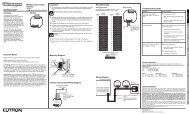
Remote Power Modules<br />
HomeWorks ® Remote Power Modules (RPMs) are used in<br />
both centralized and optimized system designs to control<br />
lighting, motor, and fan loads. There are several different<br />
models of RPMs; each model controls specific load types,<br />
as noted below. The RPMs are mounted in one of four<br />
Remote Power Panels. Model # HWI-PNL-8 and HWBP-8D<br />
house up to eight RPMs, model # HWI-PNL-5 houses up<br />
to five RPMs, and model # HWBP-2S houses up to two<br />
RPM-4Rs.<br />
DIMMING MODULE<br />
(MODEL # HW-RPM-4U-120)<br />
Each of the four outputs of the Dimming Module directly<br />
dim or switch incandescent 1 , magnetic low-voltage,<br />
neon/cold cathode, or fluorescent (Tu-Wire®) lighting.<br />
Each of the four outputs directly switch electronic lowvoltage<br />
lighting. The total capacity of a Dimming Module<br />
is 16A @ 120V (1920W/VA) 2 , comprised of any combination<br />
of load types. The total load capacity may be divided<br />
among the four outputs in any manner.<br />
ELECTRONIC LOW -VOLTA GE MODULE<br />
(MODEL # HW-RPM-4E-120)<br />
Each of the four outputs of the ELV module directly dim<br />
electronic low-voltage transformers 1 using reverse phase<br />
control technology. The total capacity of the ELV module<br />
is 16A @ 120V (1920W) 2 . The total load capacity of any<br />
individual output is limited to 9A @ 120V (1080W) 2 ,<br />
which can include up to 2.5A (300W) of incandescent<br />
lighting.<br />
MOT OR MODULE<br />
(MODEL # HW-RPM-4M-120)<br />
Each Motor Module controls four 3-wire 120V AC motors<br />
for applications such as shades, draperies, and hurricane<br />
shutters. Individual control outputs use two mechanically<br />
interlocked relays for directional control that prevents<br />
simultaneous operation of both outputs. Maximum relay<br />
contact rating is 1/4HP, 5A @ 120V for inductive loads,<br />
and 3A @ 120V for resistive loads.<br />
POWER RELAY MODULE<br />
(MODEL # HW-RPM-4R)<br />
Each of the four outputs of the Power Relay Module directly<br />
switches incandescent, neon/cold cathode, magnetic lowvoltage,<br />
electronic low-voltage, fluorescent, or high intensity<br />
discharge (HID), making this module ideal for highwattage<br />
applications, such as landscape and security lighting.<br />
The total capacity of a Power Relay Module is 64A @<br />
120V (7680W/VA). The total load capacity of any individual<br />
output is limited to 16A @ 120VAC (1920W/VA), 1/3 HP.<br />
QUIET FAN SPEED CONTROL MODULE<br />
(MODEL # HW-RPM-4FSQ-120)<br />
Each of the four outputs of the fan module controls a<br />
single ceiling fan. Each output uses quiet speed control<br />
technology that eliminates fan motor buzzing. There are<br />
five available speeds: off, low, medium, medium-high, and<br />
high. Each output is rated to control a single ceiling fan<br />
load up to 2A @ 120V.<br />
CONNECTION TO MODULE INTERFA CE<br />
All RPMs must be connected to a Module Interface housed<br />
within the same panel enclosure. If a processor is located<br />
in the same enclosure as RPMs, a processor with an integral<br />
Module Interface must be used (either model # HWI-<br />
PM-120, HWI-PM-D48-120, or HWI-PM-H48-120), which is<br />
indicated by processor model numbers containing an “M”.<br />
RPMs within an enclosure are connected to the Module<br />
Interface using a <strong>Lutron</strong>-provided harness. To minimize<br />
the effects of single power supply failure, each RPM is<br />
powered by its own internal power supply.<br />
For technical specifications, see pgs. 94-97.<br />
1 In rare cases, incandescent lamps and electronic low-voltage transformers will “buzz” or “hum.” The HW-HIFC-10-2 Filter Choke assembly reduces this<br />
hum. The Filter Choke Assembly can be installed in place of module 8 in an HWI-PNL-8 Remote Power Panel. See pg. 171 for additional information.<br />
2 For higher wattages or for load types other than those listed, a Power Booster or Interface is required. See pg. 49 for more information.<br />
38 <strong>Technical</strong> Support • 24 Hours a Day/7 Days a Week • 1.800.523.9466
Architectural-style Designer-style New Construction Existing Construction<br />
Remote Power Modules (cont.)<br />
ADDRESS SWITCH POSITION<br />
FOR HW-RPM-4U, 4E, 4R, 4FSQ<br />
Position Module Output/Purpose<br />
0<br />
All outputs OFF<br />
1-8<br />
Address for normal operation<br />
9, A<br />
Not used<br />
B<br />
Output 1 ON<br />
Use for temporary lighting and/or zone testing<br />
C<br />
Output 2 ON<br />
Use for temporary lighting and/or zone testing<br />
D<br />
Output 3 ON<br />
Use for temporary lighting and/or zone testing<br />
E<br />
Output 4 ON<br />
Use for temporary lighting and/or zone testing<br />
F<br />
All outputs ON<br />
Use for temporary lighting and/or zone testing<br />
ADDRESS SWITCH POSITION<br />
FOR HW-RPM-4M<br />
Position Module Output/Purpose<br />
0<br />
1-8<br />
9, A-D<br />
E<br />
F<br />
All relays OFF<br />
Address for normal operation<br />
Not used<br />
All raise relays ON<br />
Use for directional motor testing<br />
All lower relays ON<br />
Use for directional motor testing<br />
www.lutron.com <strong>Technical</strong> Support: product@lutron.com<br />
Enlarged view of<br />
Address Switch<br />
39<br />
INTRODUCTION DESIGN & LAYOUT COMPONENTS PRE-WIRING
INTRODUCTION DESIGN & LAYOUT COMPONENTS PRE-WIRING<br />
Architectural-style Designer-style New Construction Existing Construction<br />
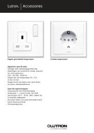
Remote Power Feed-Through Panels<br />
Remote Power Feed-Through Panels are available in two<br />
different sizes, each of which may be either surfacemounted<br />
or recess-mounted in an electrical closet or other<br />
equipment room. The number of Remote Power Panels and<br />
the types of components within them may be specified to<br />
fit the size, lighting plan, and design of a home. Remote<br />
Power Panels may be distributed throughout the home for<br />
added flexibility during installation of the line-voltage<br />
wiring.<br />
Remote Power Feed-Through Panels may contain<br />
<strong>HomeWorks®</strong> Wired Processors, Remote Power Modules, or<br />
Module Interfaces. Shown below are a few of the possible<br />
configurations.<br />
For technical specifications, see pgs. 98-101.<br />
EIGHT-MODULE<br />
REMOTE POWER FEED-THROUGH PANEL<br />
(MODEL # HWI-PNL-8)<br />
Accommodates one of the following<br />
combinations of components:<br />
Remote Power<br />
Modules (up to 8)<br />
or<br />
• 1 Wired Processor • 1 Module Interface<br />
• Up to 8 Remote • Up to 8 Remote<br />
Power Modules 1 Power Modules 1<br />
Remote Power<br />
Modules (up to 8)<br />
Wired Processor Module Interface<br />
1 One HW-HIFC-10-2 Filter Choke may be installed in place of<br />
module 8, see pg. 171.<br />
FIVE-MODULE<br />
REMOTE POWER FEED-THROUGH PANEL<br />
( MODEL # HWI-PNL-5)<br />
Accommodates the following combination of components:<br />
• 1 Module Interface<br />
• Up to 5 Remote Power Modules<br />
Note: HWI-PNL-5 cannot house a HomeWorks Wired Processor<br />
KIT FOR PERMANENT RS-232 CONNECTION<br />
IN HWI-PNL-8<br />
(MODEL # HWI-KIT-RS232)<br />
Connect Cable<br />
to Link 3<br />
Remote Power Modules<br />
(up to 5)<br />
Module Interface<br />
RS-232 cable<br />
(provided)<br />
RS-232 Connector<br />
Note: HWI-KIT-RS232 can be installed in HWI-PNL-8, allowing for<br />
a connection to RS-232 port without removing the panel<br />
cover.<br />
40 <strong>Technical</strong> Support • 24 Hours a Day/7 Days a Week • 1.800.523.9466<br />
Bracket<br />
Mounting Screws (3)
Architectural-style Designer-style New Construction Existing Construction<br />
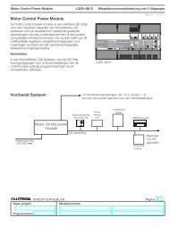
Remote Power Panels with Breakers<br />
Remote Power Panels with Breakers are available in two<br />
different sizes, each of which may be either surfacemounted<br />
or recess-mounted in an electrical closet or other<br />
equipment room. The number of Remote Power Panels and<br />
the types of components within them may be specified to<br />
fit the size, lighting plan, and design of a home. Both the<br />
HWBP-8D and HWBP-2S include factory-installed wiring<br />
from the breakers to the terminal blocks. Remote Power<br />
Panels may be distributed throughout the home for added<br />
flexibility during installation of the line-voltage wiring.<br />
Remote Power Panels with Breakers require only one feed<br />
from the main distribution panel, reducing the number of<br />
wiring connections required (feed-through panels require<br />
up to nine separate feeds).<br />
Remote Power Panels with Breakers may contain Remote<br />
Power Modules and a Module Interface.<br />
For technical specifications, see pgs. 102-105.<br />
Terminal Blocks<br />
Breakers<br />
Main Lugs<br />
Terminal Blocks<br />
Remote Power Panel with Breakers<br />
(HWBP-8D)<br />
Breakers<br />
Main Lugs<br />
Remote Power Panel with Breakers<br />
(HWBP-2S)<br />
www.lutron.com <strong>Technical</strong> Support: product@lutron.com<br />
41<br />
INTRODUCTION DESIGN & LAYOUT COMPONENTS PRE-WIRING
INTRODUCTION DESIGN & LAYOUT COMPONENTS PRE-WIRING<br />
Architectural-style Designer-style New Construction Existing Construction<br />
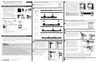
GRAFIK Eye® Preset Local Lighting Controls<br />
GRAFIK Eye Preset Local Lighting Controls allow you to<br />
easily create and recall multiple lighting scenes for the<br />
changing activities that occur in a room. Up to 16 preset<br />
scenes can be stored in each GRAFIK Eye, making them<br />
ideal for home theaters, living rooms, and dining rooms.<br />
GRAFIK Eye preset scenes can be easily adjusted manually<br />
at the Control Unit at any time. GRAFIK Eye Controls are<br />
available to dim or switch two, three, four, or six zones of<br />
incandescent, magnetic low-voltage, or neon/cold cathode<br />
lighting loads.<br />
CONNECTION TO WIRED PROCESSOR<br />
Each <strong>HomeWorks®</strong> Wired Processor has three configurable<br />
links (see pg. 30 for processor details), each capable of<br />
controlling up to eight GRAFIK Eye Control Units or WPMs.<br />
This connection requires two pair [one pair #18 AWG<br />
(1.0mm 2), one pair #18-22 AWG (1.0-0.5mm 2) twisted<br />
shielded] Class 2 wire. <strong>Lutron</strong>® wire model # GRX-CBL-<br />
346S-500 may be used. The maximum cable length is<br />
2,000 feet (610m), and this link must be wired in a daisychain<br />
configuration.<br />
For technical specifications, see pgs. 106-109.<br />
A CCESSORY CONTROLS<br />
Handheld Infrared<br />
Remote Control Transmitters<br />
GRX-IT, GRX-8IT (White Only)<br />
Controls four (or eight) scenes plus master<br />
raise/lower and off. Recalls or fine tunes<br />
light levels. Turns lighting on or off.<br />
On/Off Doorway Control<br />
NTGRX-1S<br />
Switches lighting on or off from a remote<br />
wall location. Line/main voltage control<br />
(functions as 3-way switch).<br />
FINISHES AND COLORS<br />
GRAFIK Eye Preset Local Lighting Controls are available in<br />
Architectural Matte finish plastic colors and metallic finishes.<br />
Colors include: White(WH), Beige(BE), Ivory(IV),<br />
Black(BL), Gray(GR) and Brown(BR). Metallic finishes<br />
include: Clear Anodized Aluminum(CLA), Black Anodized<br />
Aluminum(BLA), Brass Anodized Aluminum(BRA), Satin<br />
Brass(SB), Bright Brass(BB), Antique Brass(QB), Bright<br />
Chrome(BC), Satin Chrome(SC), Satin Nickel(SN), Bright<br />
Bronze(BZ), Satin Bronze(SZ), Antique Bronze(QZ), and<br />
24-karat Gold Plate(AU). Custom finishes and paint matching<br />
are also available.<br />
Zones Built-In Infrared<br />
Receiver<br />
GRAFIK EYE MAIN CONTROL UNIT<br />
INSTALLATION NOTES<br />
2-Zone<br />
installs in<br />
2-gang<br />
US wallbox<br />
GRAFIK Eye Preset Lighting Control<br />
(GRX-IA-4 shown)<br />
3-Zone<br />
installs in<br />
3-gang<br />
US wallbox<br />
4-Zone (pictured)<br />
and 6-Zone<br />
installs in 4-gang<br />
US wallbox<br />
42 <strong>Technical</strong> Support • 24 Hours a Day/7 Days a Week • 1.800.523.9466<br />
Fade<br />
Scenes<br />
Note: Use 3-1/2 inch (89mm) deep masonry wallboxes for ease of<br />
installation of GRAFIK Eye Control Units.
Architectural-style Designer-style New Construction Existing Construction<br />
Wallbox Power Module<br />
<strong>HomeWorks®</strong> Wallbox Power Modules (WPM) control six<br />
independent zones of lighting and fit in a 4-gang wallbox.<br />
The WPM is designed to be placed in closets, equipment<br />
rooms, and other locations in the home where it is “hidden”<br />
from view. Homeowners use system keypads to control<br />
the WPM.<br />
CONNECTION TO WIRED PROCESSOR<br />
The WPM is wired like a six-zone GRAFIK Eye ® control unit<br />
(IA-6). Each HomeWorks Wired Processor has three configurable<br />
links (see pg. 30 for processor details), each capable<br />
of controlling up to eight WPM or GRAFIK Eye Control<br />
Units. This connection requires two pair [one pair #18<br />
AWG (1.0mm 2), one pair #18-22 AWG (1.0-0.5mm 2) twisted<br />
shielded] Class 2 wire. <strong>Lutron</strong>® wire model # GRX-CBL-<br />
346S-500 may be used. The maximum cable length is<br />
2,000 feet (610m), and this link must be wired in a daisychain<br />
configuration.<br />
The wattage and load type specifications of the WPM are<br />
the same as six-zone GRAFIK Eye control unit (GRX-MR-<br />
6/IA-6 models). All connections on the back of the WPM<br />
are identical to those on the six-zone GRAFIK Eye control<br />
unit.<br />
DEFA ULT SCENE BUTTON<br />
Each WPM has a Default Scene button on the front of<br />
the unit that allows a user to toggle between a preprogrammed<br />
scene (defined in the HomeWorks Utility) and<br />
OFF. This scene is stored inside the WPM and can be<br />
accessed at any time. The Default Scene provides “failsafe”<br />
operation allowing the WPM to be controlled locally<br />
in the unlikely event communication to the processor is<br />
lost. Connect an NTGRX-1S control to the SSA input to<br />
allow remote operation of the Default Scene.<br />
For technical specifications, see pgs. 110-112.<br />
WPM BENEFITS:<br />
Default Scene<br />
Status LED<br />
Wallbox Power Module<br />
(HWI-WPM-6D-120)<br />
Default Scene<br />
Button<br />
• Provides a cost-effective dimming solution to jobs with<br />
lower wattage loads<br />
• Reduces overall job cost by up to 5-20% when less than<br />
96 control zones are required<br />
• Install in yachts, luxury buses, small condominiums, or<br />
anywhere space is a premium<br />
• Add remote zones without installing an enclosure<br />
Note: Use 3-1/2 inch (89mm) deep masonry wallboxes for ease of<br />
installation of GRAFIK Eye Control Units.<br />
www.lutron.com <strong>Technical</strong> Support: product@lutron.com<br />
43<br />
INTRODUCTION DESIGN & LAYOUT COMPONENTS PRE-WIRING
INTRODUCTION DESIGN & LAYOUT COMPONENTS PRE-WIRING<br />
Architectural-style Designer-style New Construction Existing Construction<br />
D48 Dimmer Interface<br />
D48 Dimmer Interfaces control up to 48 Wired Vareo ® Local<br />
Lighting Controls and are available in two configurations:<br />
either integral to a HomeWorks ® Wired Processor or as a<br />
stand-alone component. See pg. 30 for processor details.<br />
STAND-ALONE DIMMER INTERFA CES<br />
(MODEL # HWI-D48)<br />
Each stand-alone Dimmer Interface (model # HWI-D48)<br />
expands the capacity of the HomeWorks Wired Processor by<br />
providing control of up to 48 additional Wired Vareo Local<br />
Lighting Controls. Each stand-alone Dimmer Interface<br />
installs in either a 32-inch (81cm) Low-Voltage Enclosure<br />
(model # HWI-LV32-120) with a Wired Processor or in a<br />
17-inch (43cm) Low-Voltage Enclosure (model # HWI-<br />
LV17-120).<br />
INTEGRAL DIMMER INTERFA CES<br />
Two of the six HomeWorks Wired Processor model numbers<br />
(HWI-PM-D48-120 and HWI-PO-D48-120) contain integral<br />
D48 Dimmer Interfaces, allowing up to 48 Wired Vareo<br />
Local Lighting Controls to be connected directly to the<br />
processor. Processors with integral Dimmer Interfaces may<br />
be installed in either a 59-inch (150cm) Remote Power<br />
Panel (model # HWI-PNL-8) or in a 32-inch (81cm) Low-<br />
Voltage Enclosure (model # HWI-LV32-120).<br />
LOCAL LIGHTING CONTROL COMMUNICATIONS<br />
Each D48 Dimmer Interface has twelve communication<br />
buses that are used to communicate with the wired local<br />
lighting controls. Each of the twelve buses support a maximum<br />
of four uniquely-addressed Wired Vareo Local Lighting<br />
Controls. The maximum total cable length for each communication<br />
bus is 500 feet (152m). Buses may be wired in a<br />
daisy-chain, home run, star, or T-tap configuration.<br />
CONNECTION TO WIRED PROCESSOR<br />
Each HomeWorks Wired Processor has three configurable<br />
links, each capable of controlling up to four Dimmer<br />
Interfaces, one of which may be integral to the processor.<br />
No more than four Dimmer Interfaces can be connected to<br />
a single processor. All Dimmer Interfaces must be connected<br />
to the same configurable link. This connection requires<br />
two pair [one pair #18 AWG (1.0mm 2), one pair #18-22<br />
AWG (1.0-0.5mm 2) twisted shielded Class 2 wire. <strong>Lutron</strong> ®<br />
wire model # GRX-CBL-346S-500 may be used. The maximum<br />
cable length is 1,000 feet (305m), and this link<br />
must be wired in a daisy-chain configuration.<br />
Stand-Alone Dimmer Interface<br />
(HWI-D48)<br />
Processor Board<br />
Integral Module Interface<br />
Integral Dimmer Interface<br />
Integral Dimmer Interface<br />
(HWI-PO-D48-120 or HWI-PM-D48-120)<br />
Max. 1,000 ft.<br />
(305m) total<br />
Daisy-Chain only<br />
Communication Wiring<br />
For technical specifications, see pgs. 113-114.<br />
44 <strong>Technical</strong> Support • 24 Hours a Day/7 Days a Week • 1.800.523.9466<br />
HWI-D48<br />
Wired Vareo Local<br />
Lighting Controls<br />
To additional Vareo Controls.<br />
Maximum 4 Vareo Controls per bus.<br />
Maximum 12 buses per HWI-D48<br />
(total maximum is 48 Wired Vareo<br />
Controls per HWI-D48).<br />
One pair #18-22 AWG (1.0-0.5mm 2 ) twisted<br />
shielded Class 2 wire. Max. 500 ft. (152m)<br />
total per bus. Any configuration.<br />
To additional D48 Dimmer Interfaces.<br />
Maximum 4 Interfaces per link (one of which<br />
may be integral to the HomeWorks Processor).
Architectural-style Designer-style New Construction Existing Construction<br />
Wired Vareo® Local Lighting Controls<br />
LOCAL LIGHTING CONTROLS<br />
Wired Vareo Local Lighting Controls, used in both localized<br />
and optimized system designs, function much like standard<br />
dimmers and switches, but can be controlled as part<br />
of the whole-house lighting control system. Local Lighting<br />
Controls are useful in locations where single circuits of<br />
lighting need to be dimmed or switched. Wired Vareo<br />
Dimmers incorporate advanced features such as fade<br />
on/fade off, long fade off, and rapid full on. Wired Vareo<br />
Local Lighting Controls include a Front Accessible Safety<br />
Switch (FASSTM) for safe lamp replacement. <strong>HomeWorks®</strong><br />
Wired Vareo Local Lighting Controls install in single-pole,<br />
3-way, or 4-way applications.<br />
A CCESSORY CONTROL<br />
Remote switches (VETS-R) are used in conjunction with a<br />
Wired Vareo Local Lighting Control to provide 3-way and<br />
4-way control. Use up to nine VETS-R Controls with a single<br />
Wired Vareo Local Lighting Control for switching from<br />
up to ten locations.<br />
FINISHES AND COLORS<br />
Vareo Local Lighting Controls are available in Architectural<br />
Matte finish plastic colors and metallic finishes. Colors<br />
include: White(WH), Beige(BE), Ivory(IV), Gray(GR),<br />
Brown(BR), Black(BL), and Taupe(TP). Metallic finishes<br />
include: Clear Anodized Aluminum(CLA), Black Anodized<br />
Aluminum(BLA), Brass Anodized Aluminum(BRA), Satin<br />
Brass(SB), Bright Brass(BB), Antique Brass(QB), Bright<br />
Chrome(BC), Satin Chrome(SC), Satin Nickel(SN), Bright<br />
Bronze(BZ), Satin Bronze(SZ), Antique Bronze(QZ), and<br />
24-karat Gold Plate(AU). Custom finishes and paint matching<br />
are also available.<br />
G ANGING VAREO CONTROLS<br />
Gang multiple Vareo Controls together (mounted side-byside<br />
behind a single faceplate) in a series of connected<br />
wallboxes for a cleaner look. A scored section or “fin”,<br />
along each side of the mounting plate, is removed to<br />
facilitate ganging of controls. The load rating for each<br />
control must be derated when a fin has been broken.<br />
For ganging and derating information, see pg. 119.<br />
DIMMING CONTROL<br />
LOAD RATINGS<br />
HWV-600D dims a single incandescent<br />
or magnetic low-voltage circuit up to<br />
600W/VA from one location.<br />
HWV-1000D dims a single incandescent<br />
or magnetic low-voltage circuit up to<br />
1000W/VA from one location.<br />
www.lutron.com <strong>Technical</strong> Support: product@lutron.com<br />
HWV-FDB-8A dims a single fluorescent<br />
circuit up to 8A from one location when<br />
used with <strong>Lutron</strong> Hi-lume ® and ECO-10TM<br />
Electronic Fluorescent Dimming Ballasts.<br />
SWITCHING CONTROL<br />
LOAD RATINGS<br />
HWV-1000NS switches a single circuit<br />
of any lighting load type up to 1000W/VA<br />
from one location. HWV-1000NS requires<br />
a neutral wire connection.<br />
Note: For wattages exceeding those listed above or for load types<br />
other than those listed, a Power Booster or Interface is required.<br />
See pg. 49 for more information.<br />
INSTALLATION NOTE<br />
Use 3-1/2 inch (89mm) deep wallboxes for ease of installation.<br />
CONNECTION TO D48 DIMMER INTERFA CE<br />
All Wired Vareo Local Lighting Controls must be connected<br />
to a D48 Dimmer Interface. A Dimmer Interface is available<br />
as a stand-alone component (model # HWI-D48) or as<br />
an integral part of processors with model numbers containing<br />
“D48” (HWI-PM-D48-120 and HWI-PO-D48-120).<br />
Each Wired Vareo Local Lighting Control communicates<br />
with a Dimmer Interface via a one pair twisted shielded<br />
#22 AWG (0.5mm 2) cable.<br />
For technical specifications, see pgs. 115-122.<br />
45<br />
INTRODUCTION DESIGN & LAYOUT COMPONENTS PRE-WIRING
INTRODUCTION DESIGN & LAYOUT COMPONENTS PRE-WIRING<br />
Architectural-style Designer-style New Construction Existing Construction<br />
H48 Dimmer Interface<br />
H48 Dimmer Interface controls up to 48 Wired Maestro®<br />
Local Lighting Controls and are available in two configurations:<br />
either integral to a HomeWorks ® Wired Processor or<br />
as a stand-alone component.<br />
See pg. 30 for processor details.<br />
STAND-ALONE DIMMER INTERFA CE<br />
(MODEL # HWI-H48)<br />
Each stand-alone Dimmer Interface (model # HWI-H48)<br />
expands the capacity of the HomeWorks Wired Processor<br />
by providing control of up to 48 additional Wired Maestro<br />
Local Lighting Controls. Each stand-alone Dimmer<br />
Interface installs in either a 32-inch (81cm) Low-Voltage<br />
Enclosure (model # HWI-LV32-120) with a processor or<br />
in a 17-inch (43cm) Low-Voltage Enclosure (model #<br />
HWI-LV17-120).<br />
INTEGRAL DIMMER INTERFA CE<br />
Two of the six HomeWorks Wired Processor model numbers<br />
(HWI-PM-H48-120 and HWI-PO-H48-120) contain integral<br />
H48 Dimmer Interfaces, allowing up to 48 Wired Maestro<br />
Local Lighting Controls to be connected directly to the<br />
processor. Processors with integral Dimmer Interfaces may<br />
be installed in either a 59-inch (150cm) Remote Power<br />
Panel (model # HWI-PNL-8) or in a 32-inch (81cm) Low-<br />
Voltage Enclosure (model # HWI-LV32-120).<br />
LOCAL LIGHTING CONTROL COMMUNICATIONS<br />
Each H48 Dimmer Interface has six communication buses<br />
that are used to communicate with the wired local lighting<br />
controls. Each of the six buses support a maximum of<br />
eight uniquely-addressed Wired Maestro Local Lighting<br />
Controls. Each Maestro bus may have a max 500’<br />
(152.5m)per wire run but may not exceed 1000’(305m)<br />
total per bus. Buses may be wired in a daisy-chain, home<br />
run, star, or T-tap configuration.<br />
CONNECTION TO WIRED PROCESSOR<br />
Each HomeWorks Wired Processor has three configurable<br />
links, each capable of controlling up to four Dimmer<br />
Interfaces, one of which may be integral to the processor.<br />
No more than four Dimmer Interfaces can be connected to<br />
a single processor. All Dimmer Interfaces must be connected<br />
to the same configurable link. This connection requires<br />
two pair [one pair #18 AWG (1.0mm 2), one pair #18-22<br />
AWG (1.0-0.5mm 2) twisted shielded] Class 2 wire. <strong>Lutron</strong>®<br />
wire model # GRX-CBL-346S-500 may be used. The maximum<br />
cable length is 1,000 feet (305m), and this link<br />
HWI-H48<br />
Stand-Alone Dimmer Interface<br />
(HWI-H48)<br />
Processor Board<br />
Integral Module Interface<br />
Integral Dimmer Interface<br />
Max. 1,000 ft.<br />
(305m) total<br />
Daisy-Chain only<br />
Integral Dimmer Interface<br />
(HWI-PO-H48-120 or HWI-PM-H48-120)<br />
Wired Maestro<br />
Local Lighting Controls<br />
To additional Wired Maestro Controls.<br />
Maximum 8 Wired Maestro Controls per bus.<br />
Maximum 6 buses per HWI-H48 (total<br />
maximum is 48 Wired Maestro Controls<br />
per HWI-H48).<br />
One pair #18-22 AWG (1.0-0.5mm2 ) twisted shielded<br />
Class 2 wire. Each Maestro bus may have a max<br />
500’(152.5m) per wire run but may not exceed 1000’<br />
(305m) total per bus.<br />
To additional H48 Dimmer Interfaces.<br />
Maximum 4 Interfaces per link (one of which<br />
may be integral to the HomeWorks Processor).<br />
Communication Wiring<br />
For technical specifications, see pgs. 123-124.<br />
46 <strong>Technical</strong> Support • 24 Hours a Day/7 Days a Week • 1.800.523.9466
Architectural-style Designer-style New Construction Existing Construction<br />
Wired Maestro® Local Lighting Controls<br />
LOCAL LIGHTING CONTROLS<br />
Wired Maestro Local Lighting Controls, used in both localized<br />
and optimized system designs, function much like<br />
standard dimmers and switches, but can be controlled as<br />
part of the whole-house lighting control system. Local<br />
Lighting Controls are useful in locations where single<br />
circuits of lighting need to be dimmed or switched. Wired<br />
Maestro Dimmers incorporate advanced features such as<br />
fade on/fade off, long fade to off, and rapid full on. In<br />
addition, the local control may be programmed similar to<br />
a keypad button press with single and double tap functions,<br />
turning on or off multiple lights. Wired Maestro<br />
Local Lighting Controls include a Front Accessible Safety<br />
Switch (FASSTM) for safe lamp replacement. <strong>HomeWorks®</strong><br />
Wired Maestro Local Lighting Controls install in singlepole,<br />
3-way, or 4-way applications.<br />
A CCESSORY CONTROLS<br />
Remote dimmers (HD-RD) and remote switches (HD-RS)<br />
are used in conjunction with a Wired Maestro Local<br />
Lighting Control to provide 3-way and 4-way control. Use<br />
up to nine HD-RD with a single Wired Maestro Dimmer for<br />
dimming from up to ten locations. Use up to nine HD-RS<br />
with a single Wired Maestro Switch for switching from up<br />
to ten locations.<br />
FINISHES AND COLORS<br />
Wired Maestro Local Lighting Controls are available in<br />
Designer Gloss and Satin ColorsTM Matte Finishes. Designer<br />
Gloss Finishes include: White(WH), Ivory(IV), Almond(AL),<br />
Light Almond(LA), Gray(GR), Brown(BR), and Black(BL).<br />
Satin Colors include: Hot(HT), Ochre(OC), Terracotta(TC),<br />
Desert Stone(DS), Stone(ST), Limestone(LS), Blue<br />
Mist(BT), Midnight(MN), Taupe(TP), Eggshell(ES),<br />
Biscuit(BI), and Snow(SN). Claro® and Satin Colors<br />
wallplates sold separately.<br />
G ANGING MAESTRO CONTROLS<br />
Install multiple Maestro Controls together (mounted sideby-side<br />
behind a single faceplate) in a multi-gang wallbox<br />
for a cleaner look. The load rating for each control must<br />
be derated when ganging with other controls.<br />
For ganging and derating information, see pg. 130.<br />
DIMMING CONTROL<br />
LOAD RATINGS<br />
www.lutron.com <strong>Technical</strong> Support: product@lutron.com<br />
HWD-6D and HWD-6ND dim a single<br />
incandescent or magnetic low-voltage circuit<br />
up to 600W/VA from one location.<br />
HWD-6ND requires a neutral wire connection.<br />
HWD-10D and HWD-10ND dim a single<br />
incandescent or magnetic low-voltage circuit<br />
up to 1000W/VA from one location.<br />
HWD-10ND requires a neutral wire connection.<br />
SWITCHING CONTROL<br />
LOAD RATINGS<br />
HWD-8ANS switches a single circuit of<br />
any lighting load type up to 8A from one<br />
location. HWD-8ANS requires a neutral<br />
wire connection.<br />
Note: For wattages exceeding those listed above or for load types<br />
other than those listed, a neutral wire dimmer (HWD-6ND) and a<br />
Power Booster or Interface is required. See pg. 49 for more information.<br />
INSTALLATION NOTE<br />
Use 3-1/2 inch (89mm) deep wallboxes for ease of installation.<br />
CONNECTION TO H48 DIMMER INTERFA CE<br />
All Wired Maestro Local Lighting Controls must be connected<br />
to an H48 Dimmer Interface. A Dimmer Interface is<br />
available as a stand-alone component (model # HWI-H48)<br />
or as an integral part of processors with model numbers<br />
containing “H48” (HWI-PM-H48-120 and HWI-PO-H48-<br />
120). Each Wired Maestro Local Lighting Control communicates<br />
with a Dimmer Interface via a one pair twisted<br />
shielded #18-22 AWG (1.0-0.5mm 2) cable.<br />
For technical specifications, see pgs. 125-131.<br />
47<br />
INTRODUCTION DESIGN & LAYOUT COMPONENTS PRE-WIRING
INTRODUCTION DESIGN & LAYOUT COMPONENTS PRE-WIRING<br />
Architectural-style Designer-style New Construction Existing Construction<br />
RF Maestro® Local Lighting Controls<br />
LOCAL LIGHTING CONTROLS<br />
RF Maestro Local Lighting Controls, used in localized system<br />
designs, function much like standard dimmers and<br />
switches, but can be controlled as part of the whole-house<br />
lighting control system. Local Lighting Controls are useful<br />
in locations where single circuits of lighting need to be<br />
dimmed or switched. RF Maestro Dimmers incorporate<br />
advanced features such as fade on/fade off, long fade off,<br />
and rapid full on. In addition, the local control may be<br />
programmed similar to a keypad button press with single<br />
and double tap functions, turning on or off multiple<br />
lights. RF Maestro Local Lighting Controls include a Front<br />
Accessible Safety Switch (FASSTM) for safe lamp replacement.<br />
<strong>HomeWorks®</strong> RF Maestro Local Lighting Controls<br />
install in single-pole, 3-way, or 4-way applications.<br />
A CCESSORY CONTROL<br />
Remote Dimmers (HD-RD) and Remote Switches (HD-RS)<br />
are used in conjunction with a RF Maestro Local Lighting<br />
Control to provide 3-way and 4-way control. Use up to<br />
nine HD-RD with a single RF Maestro Dimmer for<br />
dimming from up to ten locations. Use up to nine HD-RS<br />
with a single RF Maestro Switch for switching from up to<br />
ten locations.<br />
FINISHES AND COLORS<br />
RF Maestro Local Lighting Controls are available in<br />
Designer Gloss and Satin ColorsTM Matte Finishes. Designer<br />
Gloss Finishes include: White(WH), Ivory(IV), Almond(AL),<br />
Light Almond(LA), Gray(GR), Brown(BR), and Black(BL).<br />
Satin Colors include: Hot(HT), Ochre(OC), Terracotta(TC),<br />
Desert Stone(DS), Stone(ST), Limestone(LS), Blue<br />
Mist(BT), Midnight(MN), Taupe(TP), Eggshell(ES),<br />
Biscuit(BI), and Snow(SN). Claro® and Satin Colors<br />
wallplates sold separately.<br />
G ANGING RF MAESTRO CONTROLS<br />
Install multiple Maestro Controls together (mounted sideby-side<br />
behind a single faceplate) in a multi-gang wallbox<br />
for a cleaner look. The load rating for each control must<br />
be derated when ganging with other controls.<br />
For ganging and derating information, see pg. 136.<br />
INSTALLATION NOTE<br />
DIMMING CONTROL<br />
LOAD RATINGS<br />
HRD-6D and HRD-6ND dim a single<br />
incandescent or magnetic low-voltage circuit<br />
up to 600W/VA from one location.<br />
HRD-6ND requires a neutral wire connection.<br />
HRD-10D and HRD-10ND dim a single<br />
incandescent or magnetic low-voltage circuit<br />
up to 1000W/VA from one location.<br />
HRD-10ND requires a neutral wire connection.<br />
SWITCHING CONTROL<br />
LOAD RATINGS<br />
HRD-8ANS switches a single circuit of<br />
any lighting load type up to 8A from one<br />
location. HRD-8ANS requires a neutral<br />
wire connection.<br />
Note: For wattages exceeding those listed above or for load types<br />
other than those listed, a neutral wire dimmer (HRD-6ND) and a<br />
Power Booster or Interface is required. See pg. 49 for more information.<br />
Use 3-1/2 inch (89mm) deep wallboxes for ease of installation.<br />
COMMUNICATION TO RF PROCESSOR<br />
All RF Maestro Local Lighting Controls must be located<br />
within 30 feet (9m) of an RF Processor or an RF Signal<br />
Repeater. Each HomeWorks RF Processor is capable of<br />
controlling up to 64 RF Local Lighting Controls.<br />
For technical specifications, see pgs. 132-137.<br />
48 <strong>Technical</strong> Support • 24 Hours a Day/7 Days a Week • 1.800.523.9466
Architectural-style Designer-style New Construction Existing Construction<br />
Power Boosters and 120V Interfaces<br />
Power Boosters and 120V Interfaces work with specific<br />
load types and/or increase the zone capacity of Wired<br />
Vareo® Local Lighting Controls, Wired and RF Maestro®<br />
Local Lighting Controls with neutral wire, GRAFIK Eye®<br />
Preset Local Lighting Controls, and Remote Power Modules.<br />
Power Boosters and 120V Interfaces are typically installed<br />
in electrical closets or other hidden locations, since they<br />
do not need to be accessed during normal operation of<br />
the <strong>HomeWorks®</strong> system.<br />
W = 4-1/2"<br />
(114mm)<br />
L = 4-1/2"<br />
(114mm)<br />
W = 4-1/2"<br />
(114mm)<br />
L = 4-1/2"<br />
(114mm)<br />
W = 4-1/2"<br />
(114mm)<br />
L = 4-1/2"<br />
(114mm)<br />
POWER BOOSTER<br />
(MODEL # NGRX-PB-WH)<br />
Single-zone interface to dim incandescent,<br />
magnetic low-voltage, and<br />
neon/cold-cathode (low/normal power<br />
factor transformers) sources. Maximum<br />
power capacity 1920W/VA @ 120V.<br />
Power Boosters are designed to be<br />
mounted in a two-gang US wallbox.<br />
FLUORESCENT INTERFA CE<br />
(MODEL # GRX-FDBI-16A-120)<br />
Single-zone interface to dim or switch<br />
<strong>Lutron</strong> ® Hi-lume ® Fluorescent Ballasts.<br />
Maximum capacity 16A (dimming) or<br />
10A (switching) @ 120V. The Fluorescent<br />
Interface is designed to be mounted in a<br />
two-gang US wallbox.<br />
ELECTRONIC LOW -VOLTA GE<br />
INTERFA CE<br />
(MODEL # ELVI-1000)<br />
Single-zone interface to dim electronic<br />
low-voltage lighting. Maximum capacity<br />
1000W @ 120V. The Electronic Low-<br />
Voltage Interface is designed to be<br />
mounted in a two-gang US wallbox.<br />
Note: All measurements have been rounded to a 1/16 inch.<br />
W = 10-3/8"<br />
(263mm)<br />
L = 14-3/4"<br />
(374mm)<br />
D = 5-13/16"<br />
(147mm)<br />
W = 6-1/8"<br />
(155mm)<br />
L = 12-1/2"<br />
(318mm)<br />
D = 3-5/16"<br />
(84mm)<br />
INSTALLATION NOTES:<br />
HI-POWER BOOSTERS<br />
(MODEL # HP-2, HP-4, HP-6)<br />
For models NGRX-PB-WH, GRX-FDBI-16A-120, and<br />
ELVI-1000, use 3-1/2 inch (89mm) deep masonry wallboxes<br />
for ease of installation. The use of a Power Booster or<br />
Interface removes the lighting load from the controlling<br />
device (Wired Vareo, Wired and RF Maestro Local Lighting<br />
Controls, GRAFIK Eye Preset Local Lighting Controls, or<br />
Remote Power Modules) and replaces it with a 40W<br />
“dummy load”. This 40W load satisfies the minimum load<br />
requirements for the controlling device.<br />
For technical specifications, see pgs. 138-145.<br />
www.lutron.com <strong>Technical</strong> Support: product@lutron.com<br />
Single-zone interface to dim or switch<br />
incandescent, magnetic low-voltage,<br />
electronic low-voltage, neon/cold cathode<br />
(low/normal power factor transformers),<br />
<strong>Lutron</strong> Fluorescent Dimming Ballasts,<br />
fluorescent non-dim, and HID (high<br />
intensity discharge) lamps.<br />
Maximum capacity is 1920 W/VA for HP-2,<br />
3840 W/VA for HP-4, and 5760 W/VA<br />
for HP-6 @ 120V. Up to five Hi-Power<br />
Boosters can be daisy-chained for additional<br />
capacity. Hi-Power Boosters are<br />
designed to be surface-mounted.<br />
0-10 VOLT INTERFA CE<br />
(MODEL # GRX-TVI)<br />
Single-zone interface to dim or switch<br />
fluorescent lights that have <strong>Lutron</strong><br />
ECO-10TM (TVE Series) Electronic<br />
Dimming Ballasts.<br />
Dims and switches any 0-10V electronic<br />
fluorescent dimming ballast powered by<br />
100-277V. Switches up to 5A of electronic<br />
capacitive fluorescent ballasts.<br />
Also switches motors - 1/4HP @ 100-<br />
127V, 1/2HP @ 200-277V.<br />
Requires 100-127V or 200-240V power<br />
for proper operation.<br />
49<br />
INTRODUCTION DESIGN & LAYOUT COMPONENTS PRE-WIRING
INTRODUCTION DESIGN & LAYOUT COMPONENTS PRE-WIRING<br />
Keypads<br />
<strong>HomeWorks®</strong> Keypads, available in many styles, colors, and<br />
finishes, provide homeowners with a simple and elegant<br />
way to operate lights, shades, motorized screens, pumps,<br />
thermostats, and many other devices. Keypads have LEDs<br />
that provide real-time status indication. <strong>Lutron</strong> provides<br />
custom engraving to clearly identify each button’s function.<br />
Keypads are available in a variety of button styles and<br />
button configurations. Since each button on every keypad<br />
model can be programmed to control any lighting load or<br />
device on the HomeWorks system, choosing a keypad for a<br />
particular location requires no more than choosing the<br />
desired style and number of buttons. Engraving can be<br />
added to any keypad. Please contact <strong>Lutron</strong>® Customer<br />
Service or your local <strong>Lutron</strong> Representative for details.<br />
Each HomeWorks Wired Processor has three configurable<br />
links, each capable of directly controlling up to 32 Wired<br />
Keypads. See pg. 30 for processor details<br />
Each HomeWorks RF Processor is capable of controlling up<br />
to 32 RF Keypads.<br />
CONNECTION TO PROCESSOR<br />
Up to 32 Wired Keypads can be directly connected to a<br />
configurable link on a HomeWorks Wired Processor using two<br />
pair [one pair #18 AWG (1.0mm 2), one pair #18-22 AWG<br />
(1.0-0.5mm 2) twisted shielded] Class 2 cable. Keypads may<br />
be wired in a daisy-chain, home run, star, or T-tap configuration.<br />
The maximum total cable length of any wire run<br />
is 1,000 feet (305m) with up to 10 keypads or interfaces.<br />
The maximum total cable length is 4,000 feet (1220m).<br />
Up to 32 RF Keypads can communicate to an RF Processor.<br />
Keypads must be located within 30 feet (9m) of the RF<br />
Processor or an RF Signal Repeater.<br />
For technical specifications, see pgs. 146-150.<br />
Designer-style<br />
seeTouchTM<br />
(Wired and RF* models)<br />
Slim Button<br />
(Wired and RF models)<br />
* Available third quarter 2003.<br />
50 <strong>Technical</strong> Support • 24 Hours a Day/7 Days a Week • 1.800.523.9466
seeTouchTM - No Insert<br />
(Wired models)<br />
seeTouch - Insert<br />
(Wired models)<br />
Slim Button<br />
(Wired models)<br />
Large Button<br />
(Wired models)<br />
Slim Button - Insert<br />
(Wired models)<br />
Architectural-style<br />
2-Button<br />
(Wired models)<br />
Signature SeriesTM<br />
(Wired models)<br />
ArchitraveTM<br />
(Wired models)<br />
European-style<br />
(Wired models)<br />
www.lutron.com <strong>Technical</strong> Support: product@lutron.com<br />
51<br />
INTRODUCTION DESIGN & LAYOUT COMPONENTS PRE-WIRING
INTRODUCTION DESIGN & LAYOUT COMPONENTS PRE-WIRING<br />
Architectural-style Designer-style New Construction Existing Construction<br />
Wired Keypads<br />
seeTouch TM KEYPADS<br />
The Architectural-style seeTouch Keypads feature large,<br />
easy-to-use buttons, plus a unique backlit engraving<br />
option that makes the keypads readable any time of the<br />
day or night. seeTouch buttons are rounded, allowing<br />
engraving to be displayed at an upward angle and increasing<br />
readability. seeTouch Keypads are available with one to<br />
seven buttons, allowing you to customize the number of<br />
functions to fit your needs.<br />
The flexible design allows the number of buttons and the<br />
configuration of the buttons to be changed after the keypad<br />
is installed.<br />
Wired seeTouch models have two contact closure inputs on<br />
the back of the unit which provide independent functions<br />
from the front buttons. Other options include configurations<br />
with infrared receiver and raise/lower buttons.<br />
FINISHES AND COLORS<br />
Architectural-style seeTouch Keypads are available in<br />
Architectural Matte finish plastic colors and metallic finishes.<br />
Colors include: White(WH), Beige(BE), Ivory(IV),<br />
Black(BL), Gray(GR), Brown(BR), and Taupe(TP). Metallic<br />
finishes include: Clear Anodized Aluminum(CLA), Black<br />
Anodized Aluminum(BLA), Brass Anodized Aluminum(BRA),<br />
Satin Brass(SB), Bright Brass(BB), Antique Brass(QB),<br />
Bright Chrome(BC), Satin Chrome(SC), Satin Nickel(SN),<br />
Bright Bronze(BZ), Satin Bronze(SZ), Antique Bronze(QZ),<br />
and 24-karat Gold Plate(AU). Custom finishes and paint<br />
matching are also available. Please contact <strong>Lutron</strong><br />
Customer Service or your local <strong>Lutron</strong> Representative for<br />
details and pricing.<br />
ORDERING METHODS<br />
a) Engraving will be decided after installation<br />
1) Order keypad with button/faceplate.<br />
ST-Model-Color<br />
2) After engraving is determined, order engraved<br />
button/faceplate kit.<br />
SK-Model-Color-E<br />
b) Engraving will be decided before installation<br />
1) Order keypad without buttons or faceplate.<br />
Non-IR: ST-NB-NONE<br />
IR: ST-NBIR-NONE<br />
2) Order engraved button/faceplate kit.<br />
SK-Model-Color-E<br />
seeTouch - NO INSERT<br />
1-Button<br />
Keypad: ST-1B-NI-XX<br />
Button/Faceplate: SK-1B-NI-XX-E<br />
Description: 1-button - no insert<br />
2-Button<br />
Keypad: ST-2B-NI-XX<br />
Button/Faceplate: SK-2B-NI-XX-E<br />
Description: 2-button - no insert<br />
3-Button<br />
Keypad: ST-3B-NI-XX<br />
Button/Faceplate: SK-3B-NI-XX-E<br />
Description: 3-button - no insert<br />
Keypad: ST-3BRL-NI-XX<br />
Button/Faceplate: SK-3BRL-NI-XX-E<br />
Description: 3-button with raise/lower - no insert<br />
4-Button<br />
Keypad: ST-4B-NI-XX<br />
Button/Faceplate: SK-4B-NI-XX-E<br />
Description: 4-button - no insert<br />
Keypad: ST-4FS-NI-XX<br />
Button/Faceplate: SK-4FS-NI-XX-E<br />
Description: 4-button favorite scenes - no insert<br />
Keypad: ST-4S-NI-XX<br />
Button/Faceplate: SK-4S-NI-XX-E<br />
Description: 4-scene - no insert<br />
Keypad: ST-4SIR-NI-XX<br />
Button/Faceplate: SK-4SIR-NI-XX-E<br />
Description: 4-scene with IR receiver - no insert<br />
5-Button<br />
Keypad: ST-5B-NI-XX<br />
Button/Faceplate: SK-5B-NI-XX-E<br />
Description: 5-button - no insert<br />
Keypad: ST-5FS-NI-XX<br />
Button/Faceplate: SK-5FS-NI-XX-E<br />
Description: 5-button favorite scene - no insert<br />
Keypad: ST-5BRL-NI-XX<br />
Button/Faceplate: SK-5BRL-NI-XX-E<br />
Description:<br />
5-button with raise/lower - no insert<br />
XX= Color Code<br />
52 <strong>Technical</strong> Support • 24 Hours a Day/7 Days a Week • 1.800.523.9466
Architectural-style Designer-style New Construction Existing Construction<br />
Wired Keypads (cont.)<br />
seeTouch TM - NO INSERT (cont.)<br />
6-Button<br />
Keypad: ST-6B-NI-XX<br />
Button/Faceplate: SK-6B-NI-XX-E<br />
Description: 6-button - no insert<br />
Keypad: ST-6BRL-NI-XX<br />
Button/Faceplate: SK-6BRL-NI-XX-E<br />
Description:<br />
6-button with raise/lower - no insert<br />
7-Button<br />
Keypad: ST-7B-NI-XX<br />
Button/Faceplate: SK-7B-NI-XX-E<br />
Description: 7-button - no insert<br />
seeTouch - INSERT<br />
1-Button<br />
Keypad: ST-1B-I-XX<br />
Button/Faceplate: SK-1B-I-XX-E<br />
Description: 1-button - insert<br />
2-Button<br />
Keypad: ST-2B-I-XX<br />
Button/Faceplate: SK-2B-I-XX-E<br />
Description: 2-button - insert<br />
3-Button<br />
Keypad: ST-3B-I-XX<br />
Button/Faceplate: SK-3B-I-XX-E<br />
Description: 3-button - insert<br />
Keypad: ST-3BRL-I-XX<br />
Button/Faceplate: SK-3BRL-I-XX-E<br />
Description: 3-button with raise/lower - insert<br />
4-Button<br />
Keypad: ST-4B-I-XX<br />
Button/Faceplate: SK-4B-I-XX-E<br />
Description: 4-button - insert<br />
Keypad: ST-4FS-I-XX<br />
Button/Faceplate: SK-4FS-I-XX-E<br />
Description: 4-button favorite scenes - insert<br />
seeTouch - INSERT (cont.)<br />
4-Button (cont.)<br />
Keypad: ST-4S-I-XX<br />
Button/Faceplate: SK-4S-I-XX-E<br />
Description: 4-scene - insert<br />
Keypad: ST-4SIR-I-XX<br />
Button/Faceplate: SK-4SIR-I-XX-E<br />
Description: 4-scene with IR receiver - insert<br />
5-Button<br />
Keypad: ST-5B-I-XX<br />
Button/Faceplate: SK-5B-I-XX-E<br />
Description: 5-button - insert<br />
Keypad: ST-5FS-I-XX<br />
Button/Faceplate: SK-5FS-I-XX-E<br />
Description: 5-button favorite scene - insert<br />
Keypad: ST-5BRL-I-XX<br />
Button/Faceplate: SK-5BRL-I-XX-E<br />
Description: 5-button with raise/lower - insert<br />
6-Button<br />
Keypad: ST-6B-I-XX<br />
Button/Faceplate: SK-6B-I-XX-E<br />
Description: 6-button - insert<br />
Keypad: ST-6BRL-I-XX<br />
Button/Faceplate: SK-6BRL-I-XX-E<br />
Description: 6-button with raise/lower - insert<br />
7-Button<br />
Keypad: ST-7B-I-XX<br />
Button/Faceplate: SK-7B-I-XX-E<br />
Description: 7-button - insert<br />
seeTouch - NO BUTTONS<br />
No-Button<br />
Keypad:<br />
Description:<br />
Keypad:<br />
Description:<br />
ST-NB-NONE<br />
No buttons<br />
www.lutron.com <strong>Technical</strong> Support: product@lutron.com<br />
ST-NBIR-NONE<br />
No buttons with IR receiver<br />
XX= Color Code<br />
53<br />
INTRODUCTION DESIGN & LAYOUT COMPONENTS PRE-WIRING
INTRODUCTION DESIGN & LAYOUT COMPONENTS PRE-WIRING<br />
Architectural-style Designer-style New Construction Existing Construction<br />
Wired Keypads (cont.)<br />
SLIM BUTTON KEYPADS<br />
Slim Button Keypads provide the largest number of buttons<br />
per gang, thereby maximizing control in minimal<br />
space. Slim Button Keypads feature multiple button<br />
columns and two large buttons which provide logical<br />
partitioning of keypad function.<br />
These keypads can be engraved below each button with<br />
names of your choosing. Engraving can be added by<br />
returning the faceplate with an engraving schedule or<br />
ordering a new faceplate with engraving.<br />
FINISHES AND COLORS<br />
Architectural-style Slim Button Keypads ship with a faceplate.<br />
Keypads are available in Architectural Matte finish<br />
plastic colors and metallic finishes. Colors include:<br />
White(WH), Beige(BE), Ivory(IV), Black(BL), Gray(GR),<br />
Brown(BR), and Taupe(TP). Metallic finishes, custom<br />
finishes, and paint matching are also available. Please<br />
contact <strong>Lutron</strong> Customer Service or your local <strong>Lutron</strong><br />
Representative for details and pricing.<br />
SLIM BUTTON INSERT KEYPADS<br />
The design of this keypad features five slim buttons in an<br />
industry-standard decorator opening, allowing multiple<br />
keypads to be easily ganged together with other devices<br />
in your home, such as audio and security controls.<br />
Slim Button Insert Keypads are available with a master<br />
raise/lower or an infrared receiver. These keypads can be<br />
engraved below each button with names of your choosing.<br />
Engraving can be added by returning the faceplate with an<br />
engraving schedule or ordering a new faceplate with<br />
engraving.<br />
FINISHES AND COLORS<br />
Architectural-style Slim Button Insert Keypads ship<br />
with a faceplate. Keypads are available in Architectural<br />
Matte finish plastic colors and metallic finishes. Colors<br />
include: White(WH), Beige(BE), Ivory(IV), Black(BL),<br />
Gray(GR), Brown(BR), and Taupe(TP). Metallic finishes,<br />
custom finishes, and paint matching are also available.<br />
Please contact <strong>Lutron</strong> Customer Service or your local<br />
<strong>Lutron</strong> Representative for details and pricing.<br />
SLIM BUTTON KEYPADS<br />
5-Button<br />
Keypad:<br />
Faceplate only:<br />
Description:<br />
10-Button<br />
Keypad:<br />
Faceplate only:<br />
Description:<br />
15-Button<br />
Keypad:<br />
Faceplate only:<br />
Description:<br />
5-Button<br />
Keypad:<br />
Faceplate only:<br />
Description:<br />
Keypad:<br />
Faceplate only:<br />
Description:<br />
Keypad:<br />
Faceplate only:<br />
Description:<br />
HWI-KP5-XX<br />
HW-B1-NFB-XX<br />
5-button with master on/off<br />
HWI-KP10-XX<br />
HW-B2-NFB-XX<br />
10-button with master on/off<br />
HWI-KP15-XX<br />
HW-B3-NFB-XX<br />
15-button with master on/off<br />
SLIM BUTTON INSERT KEYPADS<br />
HWI-5S-NM-XX<br />
NT-T7-NFB-XX<br />
5-button<br />
HWI-5S-M-XX<br />
NT-T6-NFB-XX<br />
5-button with master raise/lower<br />
HWI-5S-IR-XX<br />
NT-T6-NFB-XX<br />
5-button with IR receiver<br />
XX= Color Code<br />
54 <strong>Technical</strong> Support • 24 Hours a Day/7 Days a Week • 1.800.523.9466
Architectural-style Designer-style New Construction Existing Construction<br />
Wired Keypads (cont.)<br />
LARGE BUTTON KEYPADS<br />
The design of this keypad features large, easy-to-use<br />
buttons. Large Button Keypads feature multiple button<br />
columns which provide logical partitioning of keypad<br />
functions.<br />
These keypads can be engraved on or below each button<br />
with names of your choosing. Engraving can be added by<br />
returning the faceplate with an engraving schedule or<br />
ordering a new faceplate with engraving.<br />
FINISHES AND COLORS<br />
Architectural-style Large Button Keypads ship with a faceplate.<br />
Keypads are available in Architectural Matte finish<br />
plastic colors and metallic finishes. Colors include:<br />
White(WH), Beige(BE), Ivory(IV), Black(BL), Gray(GR),<br />
Brown(BR), and Taupe(TP). Metallic finishes, custom<br />
finishes, and paint matching are also available. Please<br />
contact <strong>Lutron</strong> Customer Service or your local <strong>Lutron</strong><br />
Representative for details and pricing.<br />
2-BUTTON KEYPAD<br />
The design of this keypad features two large buttons.<br />
2-Button Keypads are ideal for areas where intuitive<br />
control is required. Typical locations include hallways,<br />
entrances, guest rooms, bathrooms, and children’s rooms.<br />
This keypad can be engraved on each button with names<br />
of your choosing. Engraving can be added by ordering a<br />
new faceplate with engraving. 2-Button Keypads have two<br />
contact closure inputs on the back of the unit which provide<br />
independent function from the front buttons.<br />
FINISHES AND COLORS<br />
Architectural-style 2-Button Keypads ship with specified<br />
color faceplate. Keypads are available in Architectural<br />
Matte finish plastic colors and metallic finishes. Colors<br />
include: White(WH), Beige(BE), Ivory(IV), Black(BL),<br />
Gray(GR), Brown(BR), and Taupe(TP). Metallic finishes,<br />
custom finishes, and paint matching are also available.<br />
LARGE BUTTON KEYPADS<br />
6-Button<br />
Keypad:<br />
Faceplate only:<br />
Description:<br />
9-Button<br />
Keypad:<br />
Faceplate only:<br />
Description:<br />
2-BUTTON KEYPAD<br />
2-Button<br />
Keypad:<br />
Faceplate only:<br />
Description:<br />
HWI-KP-LB6-XX<br />
HWI-B4-NFB-XX<br />
6-button<br />
HWI-KP-LB9-XX<br />
HWI-B5-NFB-XX<br />
9-button<br />
HWI-2B-XX<br />
NT-T8-NFB-XX<br />
2-button<br />
www.lutron.com <strong>Technical</strong> Support: product@lutron.com<br />
XX= Color Code<br />
55<br />
INTRODUCTION DESIGN & LAYOUT COMPONENTS PRE-WIRING
INTRODUCTION DESIGN & LAYOUT COMPONENTS PRE-WIRING<br />
Architectural-style Designer-style New Construction Existing Construction<br />
Wired Keypads (cont.)<br />
SIGNATURE SERIES TM KEYPADS<br />
Signature Series Keypads allow you to incorporate the<br />
functions of standard-size <strong>HomeWorks®</strong> Keypads into a<br />
sleek, narrow-profile control that fits flush into a door<br />
trim, door jamb, or custom cabinetry. Signature Series<br />
Keypads can also be used at standard switch locations<br />
throughout your home to add a unique and elegant look.<br />
Signature Series Keypads include 3- and 4-button configurations,<br />
available with blue or green status indicators.<br />
Signature Series Keypads feature large, easy-to-use buttons,<br />
plus a unique backlit (blue or green) engraving<br />
option that makes the keypads readable any time of the<br />
day or night. Buttons are rounded, allowing engraving to<br />
be displayed at an upward angle and increasing readability.<br />
Signature Series Keypads may be mounted with or without<br />
a wallbox (WBOX-SA1-Q1).<br />
FINISHES AND COLORS<br />
Signature Series Keypads ship with solid metal faceplates.<br />
Metal finishes include: White(WH) (Monterey only),<br />
Bright Brass(BB), Satin Nickel(SN), Bright Chrome(BC),<br />
Field Paintable(FP), Unfinished Brass(UB), and 24K gold<br />
plated(AU).<br />
ORDERING METHOD<br />
1) Order keypad with buttons/faceplate.<br />
HWS-Model-Color<br />
2) After engraving is determined, order engraved<br />
button kit with same number of buttons as control.<br />
HKS-Model-Color-E<br />
SIGNATURE SERIES KEYPADS<br />
3-Button Monaco (Blue Status Indicators)<br />
Keypad:<br />
Button Kit:<br />
Description:<br />
HWS-3B-B-XX<br />
HKS-3B-BL-E<br />
3-button<br />
4-Button Monaco (Blue Status Indicators)<br />
Keypad:<br />
Button Kit:<br />
Description:<br />
HWS-4B-B-XX<br />
HKS-4B-BL-E<br />
4-button<br />
3-Button Monterey (Green Status Indicators)<br />
Keypad:<br />
Button Kit:<br />
Button Kit:<br />
Description:<br />
HWS-3B-G-XX<br />
For white Monterey Keypads only<br />
HKS-3B-WH-E<br />
For non-white Monterey Keypads<br />
HKS-3B-BL-E<br />
3-button<br />
4-Button Monterey (Green Status Indicators)<br />
Keypad:<br />
Button Kit:<br />
Button Kit:<br />
Description:<br />
Wallbox<br />
Model:<br />
Description:<br />
HWS-4B-G-XX<br />
For white Monterey Keypads only<br />
HKS-4B-WH-E<br />
For non-white Monterey Keypads<br />
HKS-4B-BL-E<br />
4-button<br />
WBOX-SA1-Q1<br />
Signature Series wallbox (1 metal box)<br />
XX= Color Code<br />
56 <strong>Technical</strong> Support • 24 Hours a Day/7 Days a Week • 1.800.523.9466
Architectural-style Designer-style New Construction Existing Construction<br />
Wired Keypads (cont.)<br />
ARCHITRAVE TM KEYPADS<br />
Architrave Keypads allow you to incorporate the functions<br />
of standard-size <strong>HomeWorks®</strong> Keypads into a sleek, narrowprofile<br />
control that fits flush into a door trim, door jamb,<br />
or custom cabinetry. Architrave Keypads can also be used<br />
at standard switch locations throughout your home to add<br />
a unique and elegant look. Architrave Keypads can be<br />
engraved, below each button, with names of your choosing.<br />
Architrave Keypads may be mounted with or without<br />
a wallbox.<br />
FINISHES AND COLORS<br />
Architrave Keypads are available with a White(WH) or<br />
Bright Brass(BB) metal faceplate. Other metallic finishes<br />
are also available. Please contact <strong>Lutron</strong> Customer Service<br />
or your local <strong>Lutron</strong> Representative for details and pricing.<br />
ORDERING METHOD<br />
1) Order keypad with buttons/faceplate.<br />
HWI-Model-Color<br />
2) After engraving is determined, order engraved<br />
faceplate with same number of buttons as control.<br />
AR-M4-Model-Color<br />
(Excludes HWI-LB5-DC1)<br />
ARCHITRAVE KEYPADS<br />
5-Button<br />
Keypad:<br />
Faceplate only:<br />
Description:<br />
Keypad:<br />
Faceplate only:<br />
Description:<br />
Keypad:<br />
Faceplate only:<br />
Description:<br />
Wallboxes<br />
241-399<br />
Wallbox for HWI-KP5-DW<br />
(1 metal box)<br />
241-663<br />
Wallbox for HWI-LB5-DC1<br />
(1 metal box)<br />
HWI-KP5-DN-XX<br />
AR-M4-DN-XX<br />
Door narrow 5-button<br />
with master on/off<br />
HWI-KP5-DW-XX<br />
AR-M4-DW-XX<br />
Door wide 5-button<br />
with master on/off<br />
HWI-LB5-DC1-XX<br />
Custom<br />
5 large buttons<br />
with raise/lower<br />
www.lutron.com <strong>Technical</strong> Support: product@lutron.com<br />
XX= Color Code<br />
57<br />
INTRODUCTION DESIGN & LAYOUT COMPONENTS PRE-WIRING
INTRODUCTION DESIGN & LAYOUT COMPONENTS PRE-WIRING<br />
Architectural-style Designer-style New Construction Existing Construction<br />
Wired Keypads (cont.)<br />
EUROPEAN-STYLE KEYPADS<br />
European-style Keypads provide the ability to control and<br />
monitor lighting, audio, video, and other home systems in<br />
a single room and throughout your home. The design of<br />
this keypad features large, rounded buttons, and large<br />
LEDs to clearly show lighting status. The unique square<br />
shape of this keypad adds distinction to any installation.<br />
European-style Keypads are available with master<br />
raise/lower and/or infrared receiver. Buttons are rounded,<br />
allowing engraving to be displayed at an upward angle<br />
and increasing readability.<br />
FINISHES AND COLORS<br />
Colors available include: Black(BL) and White(WH).<br />
Engraving is also available.<br />
ORDERING METHOD<br />
1) Order keypad with buttons/faceplate.<br />
HWI-Model-Color<br />
2) After engraving is determined, order engraved<br />
faceplate with same number of buttons as control.<br />
EFP-Model-Color<br />
EUROPEAN-STYLE KEYPADS<br />
2-Button<br />
Keypad:<br />
Faceplate only:<br />
Description:<br />
4-Button<br />
Keypad:<br />
Faceplate only:<br />
Description:<br />
Keypad:<br />
Faceplate only:<br />
Description:<br />
8-Button<br />
Keypad:<br />
Faceplate only:<br />
Description:<br />
Keypad:<br />
Faceplate only:<br />
Description:<br />
Wallboxes<br />
Model:<br />
Description:<br />
Model:<br />
Description:<br />
HWI-2SE-XX<br />
EFP-2B-SL-XX<br />
2-scene<br />
HWI-4SE-M-XX<br />
EFP-4SE-M-XX<br />
4-scene with off<br />
and raise/lower<br />
HWI-4SE-IR-XX<br />
EFP-4SE-IR-XX<br />
4-scene with off, raise/lower<br />
and IR receiver<br />
HWI-8SE-M-XX<br />
EFP-8SE-M-XX<br />
8-scene with off<br />
and raise/lower<br />
HWI-8SE-IR-XX<br />
EFP-8SE-IR-XX<br />
8-scene with off, raise/lower<br />
and IR receiver<br />
EBB-15-RD<br />
Round plastic wallbox for<br />
European-style Keypads<br />
(15 plastic wallboxes)<br />
EBB-15-SQ<br />
Square metal wallbox for<br />
European-style Keypads<br />
(15 metal wallboxes)<br />
XX= Color Code<br />
58 <strong>Technical</strong> Support • 24 Hours a Day/7 Days a Week • 1.800.523.9466
Architectural-style Designer-style New Construction Existing Construction<br />
Wired Keypads (cont.)<br />
seeTouch TM KEYPADS<br />
seeTouch KEYPADS<br />
The Designer-style seeTouch Keypads feature large, easy-<br />
Wallplate sold separately*<br />
to-use buttons, plus a unique backlit engraving option<br />
1-Button<br />
that makes the keypads readable any time of the day or<br />
Keypad*: STWD-1B-XX<br />
night. seeTouch buttons are rounded, allowing engraving<br />
Button Kit: SKD-1B-XX-E<br />
to be displayed at an upward angle and increasing readability.<br />
seeTouch Keypads are available with one to seven<br />
Description: 1-button<br />
buttons, allowing you to customize the number of func-<br />
2-Button<br />
tions to fit your need. The flexible design even allows the<br />
Keypad*: STWD-2B-XX<br />
number of buttons and the configuration of the buttons to<br />
Button Kit: SKD-2B-XX-E<br />
be changed after the keypad is installed.<br />
Description: 2-button<br />
All seeTouch models have two contact closure inputs on<br />
the back of the unit which provide independent functions<br />
from the front buttons. Other options include configurations<br />
with infrared receiver and raise/lower buttons.<br />
3-Button<br />
Keypad*: STWD-3B-XX<br />
Button Kit: SKD-3B-XX-E<br />
Description: 3-button<br />
FINISHES AND COLORS<br />
Designer-style seeTouch Keypads are available in Designer<br />
Gloss Finishes and Satin ColorsTM Matte Finishes. Designer<br />
Gloss Finishes include: White(WH), Ivory*(IV), Almond(AL),<br />
Light Almond(LA), Gray*(GR), Brown*(BR), and Black(BL).<br />
Satin Colors include: Hot*(HT), Ochre*(OC), Terracotta*(TC),<br />
Desert Stone*(DS), Stone*(ST), Limestone*(LS), Blue<br />
Mist*(BT), Midnight(MN), Taupe(TP), Eggshell(ES),<br />
Biscuit(BI), and Snow(SW).<br />
* Button and insert color differ. Refer to seeTouch Ordering Guide<br />
(367-571) for details.<br />
ORDERING METHODS<br />
a) Engraving will be decided after installation<br />
1) Order keypad with buttons.<br />
STWD-Model-Color<br />
2) After engraving is determined, order engraved<br />
button kit.<br />
SKD-Model-Color-E<br />
b) Engraving will be decided before installation<br />
1) Order keypad without buttons.<br />
Non-IR: ST-NB-NONE<br />
IR: ST-NBIR-NONE<br />
2) Order engraved button kit.<br />
SKD-Model-Color-E<br />
Keypad*:<br />
Button Kit:<br />
Description:<br />
4-Button<br />
Keypad*:<br />
Button Kit:<br />
Description:<br />
Keypad*:<br />
Button Kit:<br />
Description:<br />
Keypad*:<br />
Button Kit:<br />
Description:<br />
Keypad*:<br />
Button Kit:<br />
Description:<br />
STWD-3BRL-XX<br />
SKD-3BRL-XX-E<br />
3-button with raise/lower<br />
STWD-4B-XX<br />
SKD-4B-XX-E<br />
4-button<br />
STWD-4FS-XX<br />
SKD-4FS-XX-E<br />
4-button favorite scenes<br />
STWD-4S-XX<br />
SKD-4S-XX-E<br />
4-scene<br />
STWD-4SIR-XX<br />
SKD-4SIR-XX-E<br />
4-scene with IR receiver<br />
* Claro® Gloss and Satin Colors Matte Finishes<br />
wallplate sold separately.<br />
www.lutron.com <strong>Technical</strong> Support: product@lutron.com<br />
XX= Color Code<br />
59<br />
INTRODUCTION DESIGN & LAYOUT COMPONENTS PRE-WIRING
INTRODUCTION DESIGN & LAYOUT COMPONENTS PRE-WIRING<br />
Architectural-style Designer-style New Construction Existing Construction<br />
Wired Keypads (cont.)<br />
seeTouch TM KEYPADS (cont.)<br />
Wallplate sold separately*<br />
5-Button<br />
Keypad*:<br />
Button Kit:<br />
Description:<br />
Keypad*:<br />
Button Kit:<br />
Description:<br />
Keypad*:<br />
Button Kit:<br />
Description:<br />
6-Button<br />
Keypad*:<br />
Button Kit:<br />
Description:<br />
Keypad*:<br />
Button Kit:<br />
Description:<br />
7-Button<br />
Keypad*:<br />
Button Kit:<br />
Description:<br />
STWD-5B-XX<br />
SKD-5B-XX-E<br />
5-button<br />
seeTouch - NO BUTTONS<br />
No-Button<br />
Keypad:<br />
Description:<br />
Keypad:<br />
Description:<br />
STWD-5FS-XX<br />
SKD-5FS-XX-E<br />
5-button favorite scene<br />
STWD-5BRL-XX<br />
SKD-5BRL-XX-E<br />
5-button with raise/lower<br />
STWD-6B-XX<br />
SKD-6B-XX-E<br />
6-button<br />
STWD-6BRL-XX<br />
SKD-6BRL-XX-E<br />
6-button with raise/lower<br />
STWD-7B-XX<br />
SKD-7B-XX-E<br />
7-button<br />
ST-NB-NONE<br />
No buttons<br />
ST-NBIR-NONE<br />
No buttons with IR receiver<br />
* Claro® Gloss and Satin ColorsTM Matte Finishes<br />
wallplate sold separately.<br />
XX= Color Code<br />
60 <strong>Technical</strong> Support • 24 Hours a Day/7 Days a Week • 1.800.523.9466
Architectural-style Designer-style New Construction Existing Construction<br />
Wired Keypads (cont.)<br />
SLIM BUTTON KEYPADS<br />
The design of this keypad features five slim buttons in an<br />
industry-standard decorator opening, allowing the keypads<br />
to be easily ganged with other devices in your home, such<br />
as audio and security controls.<br />
Slim Button Keypads are available with master on/off<br />
and/or master raise/lower. The Designer-style Keypads can<br />
be custom engraved below each button.<br />
FINISHES AND COLORS<br />
Designer-style Slim Button Keypads are available in<br />
Designer Gloss Finishes and Satin ColorsTM Matte Finishes.<br />
Designer Gloss Finishes include: White(WH), Ivory(IV),<br />
Almond(AL), Light Almond(LA), Gray(GR), Brown(BR), and<br />
Black(BL).<br />
Satin Colors include: Hot(HT), Ochre(OC), Terracotta(TC),<br />
Desert Stone(DS), Stone(ST), Limestone(LS), Blue<br />
Mist(BT), Midnight(MN), Taupe(TP), Eggshell(ES),<br />
Biscuit(BI), and Snow(SW).<br />
ORDERING METHODS<br />
1) Order keypad with buttons.<br />
HWD-Model-Color<br />
2) After engraving is determined, order engraved<br />
button kit.<br />
HKD-Model-Color-E<br />
SLIM BUTTON KEYPADS<br />
Wallplate sold separately*<br />
5-Button<br />
Keypad:<br />
Button Kit:<br />
Description:<br />
Keypad:<br />
Button Kit:<br />
Description:<br />
10-Button<br />
Keypad:<br />
Button Kit:<br />
Description:<br />
Keypad:<br />
Button Kit:<br />
Description:<br />
HWD-5KP-XX<br />
HKD-5KP-XX-E<br />
5-button with master on/off<br />
HWD-5RL-XX<br />
HKD-5RL-XX-E<br />
5-button with raise/lower<br />
HWD-10KP-XX<br />
HKD-10KP-XX-E<br />
10-button with master on/off<br />
HWD-10RL-XX<br />
HKD-10RL-XX-E<br />
10-button with master on/off<br />
and raise/lower<br />
* Claro® Gloss and Satin Colors Matte Finishes<br />
wallplate sold separately.<br />
www.lutron.com <strong>Technical</strong> Support: product@lutron.com<br />
XX= Color Code<br />
61<br />
INTRODUCTION DESIGN & LAYOUT COMPONENTS PRE-WIRING
INTRODUCTION DESIGN & LAYOUT COMPONENTS PRE-WIRING<br />
Architectural-style Designer-style New Construction Existing Construction<br />
RF Keypads<br />
seeTouch TM KEYPADS<br />
seeTouch KEYPADS<br />
Designer-style seeTouch Keypads feature large, easy-to-use<br />
Wallplate sold separately*<br />
buttons, plus a unique backlit engraving option that<br />
1-Button<br />
makes the keypads readable any time of the day or night.<br />
Keypad*: STRD-1B-XX<br />
seeTouch buttons are rounded, allowing engraving to be<br />
Button Kit: SKD-1B-XX-E<br />
displayed at an upward angle, increasing readability.<br />
seeTouch Keypads are available with one to seven buttons,<br />
Description: 1-button<br />
allowing you to customize the number of functions to fit<br />
2-Button<br />
your need. The flexible design even allows the number of<br />
Keypad*: STRD-2B-XX<br />
buttons and the configuration of the buttons to be<br />
Button Kit: SKD-2B-XX-E<br />
changed after the keypad is installed.<br />
Description: 2-button<br />
Options include configurations with infrared receiver and<br />
raise/lower buttons.<br />
3-Button<br />
Keypad*: STRD-3B-XX<br />
FINISHES AND COLORS<br />
Button Kit: SKD-3B-XX-E<br />
Description: 3-button<br />
Designer-style seeTouch Keypads are available in Designer<br />
Gloss Finishes and Satin ColorsTM Matte Finishes. Designer<br />
Gloss Finishes include: White(WH), Ivory*(IV), Almond(AL),<br />
Light Almond(LA), Gray*(GR), Brown*(BR), and Black(BL).<br />
Satin Colors include: Hot*(HT), Ochre*(OC), Terracotta*(TC),<br />
Desert Stone*(DS), Stone*(ST), Limestone*(LS), Blue<br />
Mist*(BT), Midnight(MN), Taupe(TP), Eggshell(ES),<br />
Biscuit(BI), and Snow(SW).<br />
* Button and insert color differ. Refer to seeTouch Ordering Guide<br />
(367-571) for details.<br />
ORDERING METHODS<br />
a) Engraving will be decided after installation<br />
1) Order keypad with buttons.<br />
STRD-Model-Color<br />
2) After engraving is determined, order engraved<br />
button kit.<br />
SKD-Model-Color-E<br />
b) Engraving will be decided before installation<br />
1) Order keypad without buttons.<br />
Non-IR: STR-NB-NONE<br />
IR: STR-NBIR-NONE<br />
2) Order engraved button kit.<br />
SKD-Model-Color-E<br />
Keypad*:<br />
Button Kit:<br />
Description:<br />
4-Button<br />
Keypad*:<br />
Button Kit:<br />
Description:<br />
Keypad*:<br />
Button Kit:<br />
Description:<br />
Keypad*:<br />
Button Kit:<br />
Description:<br />
Keypad*:<br />
Button Kit:<br />
Description:<br />
STRD-3BRL-XX<br />
SKD-3BRL-XX-E<br />
3-button with raise/lower<br />
STRD-4B-XX<br />
SKD-4B-XX-E<br />
4-button<br />
STRD-4FS-XX<br />
SKD-4FS-XX-E<br />
4-button favorite scenes<br />
STRD-4S-XX<br />
SKD-4S-XX-E<br />
4-scene<br />
STRD-4SIR-XX<br />
SKD-4SIR-XX-E<br />
4-scene with IR receiver<br />
* Claro® Gloss and Satin ColorsTM Matte Finishes<br />
wallplate sold separately.<br />
XX= Color Code<br />
62 <strong>Technical</strong> Support • 24 Hours a Day/7 Days a Week • 1.800.523.9466
Architectural-style Designer-style New Construction Existing Construction<br />
RF Keypads (cont.)<br />
seeTouch TM KEYPADS (cont.)<br />
Wallplate sold separately*<br />
5-Button<br />
Keypad*:<br />
Button Kit:<br />
Description:<br />
Keypad*:<br />
Button Kit:<br />
Description:<br />
Keypad*:<br />
Button Kit:<br />
Description:<br />
6-Button<br />
Keypad*:<br />
Button Kit:<br />
Description:<br />
Keypad*:<br />
Button Kit:<br />
Description:<br />
7-Button<br />
Keypad*:<br />
Button Kit:<br />
Description:<br />
STRD-5B-XX<br />
SKD-5B-XX-E<br />
5-button<br />
STRD-5FS-XX<br />
SKD-5FS-XX-E<br />
5-button favorite scene<br />
STRD-5BRL-XX<br />
SKD-5BRL-XX-E<br />
5-button with raise/lower<br />
STRD-6B-XX<br />
SKD-6B-XX-E<br />
6-button<br />
STRD-6BRL-XX<br />
SKD-6BRL-XX-E<br />
6-button with raise/lower<br />
STRD-7B-XX<br />
SKD-7B-XX-E<br />
7-button<br />
seeTouch - NO BUTTONS<br />
No-Button<br />
Keypad:<br />
Description:<br />
Keypad:<br />
Description:<br />
STR-NB-NONE<br />
No buttons<br />
STR-NBIR-NONE<br />
No buttons with IR receiver<br />
* Claro® Gloss and Satin ColorsTM Matte Finishes<br />
wallplate sold separately.<br />
www.lutron.com <strong>Technical</strong> Support: product@lutron.com<br />
XX= Color Code<br />
63<br />
INTRODUCTION DESIGN & LAYOUT COMPONENTS PRE-WIRING
INTRODUCTION DESIGN & LAYOUT COMPONENTS PRE-WIRING<br />
Architectural-style Designer-style New Construction Existing Construction<br />
RF Keypads (cont.)<br />
SLIM BUTTON KEYPADS<br />
The design of this keypad features five slim buttons in an<br />
industry-standard decorator opening, allowing multiple<br />
keypads to be easily ganged with other devices in your<br />
home, such as audio and security controls.<br />
Slim Button Keypads are available with master on/off<br />
and/or master raise/lower. The Designer-style Keypads can<br />
be custom engraved below each button.<br />
FINISHES AND COLORS<br />
Designer-style Slim Button Keypads are available in<br />
Designer Gloss Finishes and Satin ColorsTM Matte Finishes.<br />
Designer Gloss Finishes include: White(WH), Ivory(IV),<br />
Almond(AL), Light Almond(LA), Gray(GR), Brown(BR), and<br />
Black(BL). Satin Colors include: Hot(HT), Ochre(OC),<br />
Terracotta(TC), Desert Stone(DS), Stone(ST),<br />
Limestone(LS), Blue Mist(BT), Midnight(MN), Taupe(TP),<br />
Eggshell(ES), Biscuit(BI), and Snow(SW).<br />
ORDERING METHODS<br />
1) Order keypad with insert.<br />
HRD-Model-Color<br />
2) After engraving is determined, order engraved<br />
insert with same button configuration as control.<br />
HKD-Model-Color-E<br />
SLIM BUTTON KEYPADS<br />
Wallplate sold separately*<br />
5-Button<br />
Keypad*:<br />
Button Kit:<br />
Description:<br />
Keypad*:<br />
Button Kit:<br />
Description:<br />
10-Button<br />
Keypad*:<br />
Button Kit:<br />
Description:<br />
Keypad*:<br />
Button Kit:<br />
Description:<br />
HRD-5KP-XX<br />
HKD-5KP-XX-E<br />
5-button with master on/off<br />
HRD-5RL-XX<br />
HKD-5RL-XX-E<br />
5-button with raise/lower<br />
HRD-10KP-XX<br />
HKD-10KP-XX-E<br />
10-button with master on/off<br />
HRD-10RL-XX<br />
HKD-10RL-XX-E<br />
10-button with master on/off<br />
and raise/lower<br />
* Claro® Gloss and Satin ColorsTM Matte Finishes<br />
wallplate sold separately.<br />
XX= Color Code<br />
64 <strong>Technical</strong> Support • 24 Hours a Day/7 Days a Week • 1.800.523.9466
Architectural-style Designer-style New Construction Existing Construction<br />
RF Tabletop Keypads<br />
<strong>HomeWorks®</strong> RF Tabletop Keypads provide maximum flexibility<br />
to locate the devices where the homeowner can conveniently<br />
monitor and control lighting, window treatments,<br />
and other home systems. Tabletop keypads are ideal for<br />
night stands, coffee tables, and kitchen counters. Keypad<br />
buttons are programmed to create a customized control<br />
that meets the individual needs of each home. Keypads<br />
have LEDs that provide real-time status indication. Custom<br />
engraving is available to clearly identify each button’s<br />
function. RF Tabletop Keypads can be part of any system<br />
design, whether it is localized, centralized, or optimized.<br />
SLIM AND LARGE BUTTON<br />
RF TABLETOP KEYPADS<br />
The RF Tabletop Keypads are available with Slim Button<br />
(5-, 10-, or 15-button) and Large Button (6-button)<br />
configurations. All of these models are available with or<br />
without raise/lower buttons. Metal faceplates can be<br />
added to enhance the look of any RF Tabletop Keypad.<br />
Units can be purchased as plug-in only (-A) or plugin/battery<br />
combo units (-C).<br />
COMMUNICATION TO RF PROCESSOR<br />
All RF Tabletop Keypads must be located within 30 feet<br />
(9m) of an RF Processor or an RF Signal Repeater. Each<br />
HomeWorks RF Processor is capable of controlling up to 32<br />
RF Keypads. The Tabletop Keypad counts as one of the 32<br />
RF Keypads. Each HomeWorks system is capable of controlling<br />
up to 32 plug-in/battery combo keypads (-C).<br />
FINISHES AND COLORS<br />
Tabletop Keypad colors include: Snow(SW) and<br />
Midnight(MN). Faceplate finishes and colors include:<br />
Snow(SW) and Midnight(MN) (plastic), Satin Brass(SB),<br />
Bright Brass(BB), Bright Chrome(BC), Clear Anodized<br />
Aluminum(CLA), Black Anodized Aluminum(BLA), Brass<br />
Anodized Aluminum(BRA), Antique Brass(QB), Antique<br />
Bronze(QZ), Satin Chrome(SC), Satin Nickel(SN), and<br />
Bright Nickel(BN).<br />
ORDERING METHOD<br />
1) Order keypad with buttons/faceplate.<br />
HRT-Model-Color<br />
2) After engraving is determined, order engraved<br />
faceplate with same number of buttons as control.<br />
HKT-Model-Color-E<br />
For technical specifications, see pgs. 149-150.<br />
SLIM BUTTON<br />
5-Button<br />
Keypad:<br />
Faceplate only:<br />
Description:<br />
Keypad:<br />
Faceplate only:<br />
Description:<br />
10-Button<br />
Keypad:<br />
Faceplate only:<br />
Description:<br />
Keypad:<br />
Faceplate only:<br />
Description:<br />
15-Button<br />
Keypad:<br />
Faceplate only:<br />
Description:<br />
Keypad:<br />
Faceplate only:<br />
Description:<br />
LARGE BUTTON<br />
6-Button<br />
Keypad:<br />
Faceplate only:<br />
Description:<br />
Keypad:<br />
Faceplate only:<br />
Description:<br />
www.lutron.com <strong>Technical</strong> Support: product@lutron.com<br />
HRT-5KP-A-XX<br />
HRT-5KP-C-XX<br />
HKT-5KP-XX-E<br />
5-button with master on/off<br />
HRT-5RL-A-XX<br />
HRT-5RL-C-XX<br />
HKT-5RL-XX-E<br />
5-button with master on/off<br />
and raise/lower<br />
HRT-10KP-A-XX<br />
HRT-10KP-C-XX<br />
HKT-10KP-XX-E<br />
10-button with master on/off<br />
HRT-10RL-A-XX<br />
HRT-10RL-C-XX<br />
HKT-10RL-XX-E<br />
10-button with master on/off<br />
and raise/lower<br />
HRT-15KP-A-XX<br />
HRT-15KP-C-XX<br />
HKT-15KP-XX-E<br />
15-button with master on/off<br />
HRT-15RL-A-XX<br />
HRT-15RL-C-XX<br />
HKT-15RL-XX-E<br />
15-button with master on/off<br />
and raise/lower<br />
HRT-6LKP-A-XX<br />
HRT-6LKP-C-XX<br />
HKT-6LKP-XX-E<br />
6-button<br />
HRT-6LRL-A-XX<br />
HRT-6LRL-C-XX<br />
HKT-6LRL-XX-E<br />
6-button with raise/lower<br />
XX= Color Code<br />
65<br />
INTRODUCTION DESIGN & LAYOUT COMPONENTS PRE-WIRING
INTRODUCTION DESIGN & LAYOUT COMPONENTS PRE-WIRING<br />
Architectural-style Designer-style New Construction Existing Construction<br />
RF Lamp Dimmer<br />
RF LAMP DIMMER<br />
(MODEL # HRT-3LD)<br />
<strong>HomeWorks®</strong> RF Lamp Dimmers allow table and floor lamps<br />
to be included in the HomeWorks lighting control system.<br />
Each RF Lamp Dimmer controls one table or floor lamp<br />
with simple and intuitive buttons for on/off and raise/lower.<br />
Simple to install, RF Lamp Dimmers are plugged into any<br />
standard wall outlet. Built-in intelligence allows each<br />
RF Lamp Dimmer to be controlled from the HomeWorks<br />
Keypad in the home, as well as from touchscreens,<br />
universal remotes, and home automation controls.<br />
RF Lamp Dimmers incorporate advanced features such<br />
as fade on/fade off, long fade to off, and rapid full on.<br />
In addition, the local control may be programmed similar<br />
to a keypad button press with single and double tap<br />
functions, turning on or off multiple lights. RF Lamp<br />
Dimmers are suitable for any home and can be added to<br />
a HomeWorks system at any time.<br />
FINISHES AND COLORS<br />
RF Lamp Dimmers are available in Snow(SW)<br />
and Midnight (MN).<br />
DIMMING CONTROL LOAD RATINGS<br />
HRT-3LD dims a single incandescent or magnetic lowvoltage<br />
circuit up to 300W/VA.<br />
COMMUNICATION TO RF PROCESSOR<br />
All RF Lamp Dimmers must be located within 30 feet (9m)<br />
of an RF Processor or an RF Signal Repeater. Each<br />
HomeWorks RF Processor is capable of controlling up to<br />
64 RF Local Lighting controls.<br />
For technical specifications, see pg. 151.<br />
RF Lamp Dimmer<br />
(HRT-3LD)<br />
66 <strong>Technical</strong> Support • 24 Hours a Day/7 Days a Week • 1.800.523.9466
Architectural-style Designer-style New Construction Existing Construction<br />
RF Visor Controls<br />
RF VISOR RECEIVER AND TRANSMITTER<br />
(MODEL # HR-VCRX-SW AND HR-VCTX-SW)<br />
<strong>HomeWorks®</strong> RF Visor Controls may be used in any system<br />
design that utilizes an RF Processor. These devices provide<br />
control of lighting and other equipment from your car<br />
with just the touch of a button. The RF Visor Receiver has<br />
four dry contact outputs that can be used for garage doors<br />
or gates. Turn lights on or off, set scenes, or turn on<br />
Vacation Mode from your car as you are leaving your<br />
home. Pre-printed labels are provided to clearly identify<br />
each button’s function. Each transmitter provides up to<br />
seven functions. Up to ten transmitters will work with one<br />
receiver.<br />
FINISHES AND COLORS<br />
RF Visor Controls’ colors include: Snow(SW).<br />
COMMUNICATION TO RF PROCESSOR<br />
The RF Visor Receiver must be located within 30 feet (9m)<br />
of an RF Processor or an RF Signal Repeater. Each HomeWorks<br />
RF Processor is capable of controlling up to 32 RF Keypads.<br />
The RF Visor Receiver counts as one of the 32 RF Keypads.<br />
For technical specifications, see pg. 152.<br />
RF Visor Receiver and Transmitter<br />
(HR-VCRX-SW and HR-VCTX-SW)<br />
HomeLink and the HomeLink Compatible logo are registered<br />
trademarks of Johnson Controls.<br />
www.lutron.com <strong>Technical</strong> Support: product@lutron.com<br />
67<br />
INTRODUCTION DESIGN & LAYOUT COMPONENTS PRE-WIRING
INTRODUCTION DESIGN & LAYOUT COMPONENTS PRE-WIRING<br />
Architectural-style Designer-style New Construction Existing Construction<br />
Contact Closure Interfaces<br />
Contact Closure Interfaces allow simple integration of the<br />
<strong>HomeWorks®</strong> system with other equipment throughout the<br />
house. Equipment such as driveway sensors, photocells,<br />
and security systems are able to activate lighting scenes<br />
and other HomeWorks system events through the use of<br />
Contact Closure Input Interfaces (HWI-CCI-8 and HR-CCI-<br />
6-SW). Equipment such as shades, screens, gates, spas,<br />
and thermostats can be controlled by the HomeWorks system<br />
through the use of Contact Closure Output Interfaces<br />
(HWI-CCO-8). In addition, both the HWI-CCI-8 and the<br />
HWI-CCO-8 provide an infrared (IR) input that can be used<br />
to initiate HomeWorks system events using IR remote controls.<br />
Contact Closure Interfaces (HWI-CCI-8 and HWI-CCO-8)<br />
can be mounted in any of three different enclosures:<br />
HWI-LV32-120, HWI-LV17-120, and HWI-ENC-CC.<br />
Note: Wired seeTouchTM Keypads and Wired 2-Button<br />
Keypads also include contact closure inputs.<br />
See pg. 55 for 2-Button Keypad details.<br />
See pg. 52 and 57 for SeeTouch Keypad details.<br />
CONTA CT CLOSURE INPUT INTERFA CES<br />
Many electronic systems and devices have the capability<br />
to provide status or control in the form of dry contact<br />
closure outputs. Each individual device output can be<br />
connected to one of the Contact Closure Inputs on a contact<br />
Closure Input Interface. These contact closure inputs<br />
are programmed in the same fashion as the buttons on a<br />
HomeWorks Keypad. For example, a driveway sensor can be<br />
connected to a CCI Interface and programmed to activate<br />
a “Welcome Home” scene.<br />
Each of the contact closure inputs can be individually<br />
programmed as normally-open or normally-closed.<br />
WIRED CONTA CT CLOSURE INPUT INTERFA CE<br />
(MODEL # HWI-CCI-8)<br />
Each dry contact closure input has an LED indicator that<br />
shows the state of the connected device. The Contact<br />
Closure Input Interface has an IR receiver that is programmed<br />
independently of the contact closure inputs. This<br />
receiver allows <strong>Lutron</strong>® Handheld IR Transmitters (GRX-IT,<br />
and GRX-8IT) to function as “wireless keypads” when used<br />
in conjunction with standard IR repeater systems. The<br />
<strong>Lutron</strong> IR codes can be learned by most learning remotes,<br />
allowing audio/video remotes to control the lighting system.<br />
Wired Contact Closure Input Interface<br />
(HWI-CCI-8)<br />
CONNECTION TO WIRED PROCESSOR<br />
Each Contact Closure Interface uses one keypad address.<br />
Up to 32 can be directly connected to a configurable link<br />
on a HomeWorks Processor using two pair [one pair #18<br />
AWG (1.0mm 2), one pair #18-22 AWG (1.0-0.5mm 2) twisted<br />
shielded] Class 2 cable. Contact Closure Interfaces must<br />
reside on a link that has been configured for keypads, and<br />
may be wired in a daisy-chain, home run, or T-tap configuration.<br />
The maximum total cable length of any wire run<br />
is 1,000 feet (305m) with up to 10 keypads or interfaces.<br />
The maximum total cable length is 4,000 feet (1220m).<br />
68 <strong>Technical</strong> Support • 24 Hours a Day/7 Days a Week • 1.800.523.9466
Architectural-style Designer-style New Construction Existing Construction<br />
Contact Closure Interfaces (cont.)<br />
RF CONTA CT CLOSURE INPUT INTERFA CE<br />
(MODEL # HR-CCI-6-SW)<br />
Devices that provide contact closure outputs are not<br />
always located near the processor. RF CCI Interfaces can<br />
be distributed throughout the home, locating them near<br />
the devices to which they are interfacing. The RF CCI<br />
Interface has six contact closure inputs which are<br />
programmed in the same fashion as the buttons on a<br />
<strong>HomeWorks®</strong> Keypad. Six buttons allow you to test each<br />
contact closure input’s programming from the front of the<br />
control. Each dry contact closure input has an LED indicator<br />
that shows the state of the connected device.<br />
COMMUNICATION TO RF PROCESSOR<br />
All RF CCI Interfaces must be located within 30 feet (9m)<br />
of an RF Processor or an RF Signal Repeater. Each<br />
HomeWorks RF Processor is capable of controlling up to 32<br />
RF Keypads. Each RF CCI Interface counts as one of the 32<br />
RF Keypads.<br />
For technical specifications, see pgs. 155-156.<br />
RF Contact Closure Input Interface<br />
(HR-CCI-6-SW)<br />
www.lutron.com <strong>Technical</strong> Support: product@lutron.com<br />
69<br />
INTRODUCTION DESIGN & LAYOUT COMPONENTS PRE-WIRING
INTRODUCTION DESIGN & LAYOUT COMPONENTS PRE-WIRING<br />
Architectural-style Designer-style New Construction Existing Construction<br />
Contact Closure Interfaces (cont.)<br />
WIRED CONTA CT CLOSURE OUTPUT INTERFA CE<br />
(MODEL # HWI-CCO-8)<br />
Many electronic devices have dry contact closure inputs,<br />
allowing them to be controlled by an external system. The<br />
HomeWorks ® system uses the Contact Closure Output Board<br />
to control pumps, thermostats, audio/video, and other<br />
equipment supplied with dry contact closure inputs. Each<br />
CCO Interface has eight individually-controlled contact<br />
closure outputs and eight corresponding push buttons<br />
with LED indicators. When placed in “manual control<br />
mode”, the push buttons on the board are used to change<br />
the state of each relay, allowing functional testing of the<br />
devices that are being controlled. Both normally-open and<br />
normally-closed relay contacts are provided for each CCO,<br />
and each output can be programmed to provide either<br />
momentary (pulsed) or maintained (latching) functionality.<br />
These CCOs can be assigned to any keypad button or timeclock<br />
event in the same manner as any lighting load. In a<br />
typical application, a HomeWorks Keypad button can be<br />
programmed to activate an output on a CCO Interface that<br />
is connected to a motorized window treatment. The CCO<br />
Interface has an IR receiver that is programmed independently<br />
of the contact closure outputs. This receiver allows<br />
<strong>Lutron</strong>® Handheld IR Transmitters (GRX-IT, and GRX-8IT) to<br />
function as “wireless keypads” when used in conjunction<br />
with standard IR repeater systems. The <strong>Lutron</strong> IR codes<br />
can be learned by most learning remotes, allowing<br />
audio/video remotes to control the lighting control system.<br />
CONNECTION TO WIRED PROCESSOR<br />
Each Contact Closure Interface uses one keypad address.<br />
Up to 32 can be directly connected to a configurable link<br />
on a HomeWorks Processor using two pair [one pair #18<br />
AWG (1.0mm 2), one pair #18-22 AWG (1.0-0.5mm 2) twisted<br />
shielded] Class 2 cable. Contact Closure Interfaces must<br />
reside on a link that has been configured for keypads, and<br />
may be wired in a daisy-chain, home run, or T-tap configuration.<br />
The maximum total cable length of any wire run<br />
is 1,000 feet (305m) with up to 10 keypads or interfaces.<br />
The maximum total cable length is 4,000 feet (1220m).<br />
For technical specifications, see pgs. 157-158.<br />
Wired Contact Closure Output Interface<br />
(HWI-CCO-8)<br />
70 <strong>Technical</strong> Support • 24 Hours a Day/7 Days a Week • 1.800.523.9466
Architectural-style Designer-style New Construction Existing Construction<br />
Low-Voltage Enclosures<br />
Low-Voltage Enclosures are available in three different<br />
sizes, each of which may be either surface-mounted or<br />
flush-mounted in an electrical closet or equipment room.<br />
Both the number of enclosures and the types of components<br />
within them are customized to fit the size, lighting<br />
plan, and design of a home. Low-Voltage Enclosures can<br />
be distributed throughout the home near the rooms they<br />
are controlling to provide maximum flexibility during<br />
installation of the low-voltage wiring.<br />
32" (81CM) LOW -VOLTA GE ENCLOSURE<br />
(MODEL # HWI-LV32-120)<br />
32-inch Low-Voltage Enclosures accommodate several components<br />
including Wired Processors, Dimmer Interfaces,<br />
Wired Contact Closure Interfaces, and Wire Landing<br />
Boards. Shown are a few of the possible configurations.<br />
Low-Voltage Enclosures cannot house Remote Power<br />
Modules (RPMs).<br />
For technical specifications, see pgs. 159-160.<br />
CONTA CT CLOSURE INTERFA CE SUBPLATE<br />
(MODEL # HWI-SUB32-CC9)<br />
The <strong>HomeWorks®</strong> Contact Closure Interface Subplate<br />
installs in the HWI-LV32-120 enclosure allowing up to<br />
nine Contact Closure Interfaces to be mounted in one<br />
panel. Install the HWI-SUB32-CC9 using the three processor<br />
mounting screws already installed in the enclosure,<br />
plus two additional screws provided with the HWI-SUB32-<br />
CC9.<br />
For technical specifications, see pg. 161.<br />
Wire Landing Boards<br />
(up to 3)<br />
• 1 Wired Processor<br />
• Up to 3 Wire<br />
Landing Boards<br />
• 1 Dimmer Interface<br />
Transformer<br />
(for H48<br />
Dimmer<br />
Interface)<br />
Wired<br />
Processor<br />
Dimmer<br />
Interface<br />
Note: Low-Voltage Enclosures cannot house Remote Power Modules (RPMs). For technical specifications, see pgs 161-164.<br />
www.lutron.com <strong>Technical</strong> Support: product@lutron.com<br />
or<br />
Subplate<br />
mounting<br />
locations (5)<br />
Contact Closure<br />
Interface<br />
Subplate<br />
Wire Landing Boards<br />
(up to 2)<br />
• 1 Wired Processor<br />
• Up to 2 Wire<br />
Landing Boards<br />
• Up to 2 Contact<br />
Closure Interfaces<br />
Wired<br />
Processor<br />
Contact Closure<br />
Interfaces<br />
(up to 2)<br />
Contact Closure<br />
Interfaces<br />
(up to 9)<br />
• Up to 9 Contact Closure<br />
Interfaces<br />
71<br />
INTRODUCTION DESIGN & LAYOUT COMPONENTS PRE-WIRING
INTRODUCTION DESIGN & LAYOUT COMPONENTS PRE-WIRING<br />
Architectural-style Designer-style New Construction Existing Construction<br />
Low-Voltage Enclosures (cont.)<br />
17" (44CM) LOW -VOLTA GE ENCLOSURE<br />
(MODEL # HWI-LV17-120)<br />
17-inch Low-Voltage Enclosures accommodate several<br />
components including Dimmer Interfaces, Contact Closure<br />
Interfaces, and Wire Landing Boards. Shown are a few of<br />
the possible configurations.<br />
For technical specifications, see pgs. 162-163.<br />
Wire Landing Board<br />
• 1 Dimmer Interface<br />
• 1 Wire Landing Board<br />
10" (25 CM) LOW -VOLTA GE ENCLOSURE<br />
(MODEL # HWI-ENC-CC)<br />
The 10-inch Low-Voltage Enclosure accommodates one<br />
Contact Closure Interface (HWI-CCI-8 or HWI-CCO-8).<br />
Shown is the mounting configuration.<br />
For technical specifications, see pg. 164.<br />
Transformer for<br />
Dimmer Interface<br />
Dimmer Interface<br />
Contact Closure<br />
Interfaces<br />
(up to 2)<br />
• Up to 2 Contact Closure Boards<br />
Contact Closure<br />
Interface<br />
• 1 Contact Closure Board<br />
• 1 Wire Landing Board<br />
Wire Landing Board<br />
Contact Closure<br />
Interface<br />
• 1 Contact Closure Interface<br />
72 <strong>Technical</strong> Support • 24 Hours a Day/7 Days a Week • 1.800.523.9466<br />
or<br />
or
Architectural-style Designer-style New Construction Existing Construction<br />
Wire Landing Board<br />
WIRE LANDING BOARD<br />
(MODEL # HWI-WLB)<br />
The Wire Landing Board is a wiring aid consisting of<br />
a printed circuit board with three sets of four terminal<br />
blocks. Each of these sets of terminal blocks is connected<br />
pin-to-pin, simplifying home run wiring. The Wire Landing<br />
Board is installed in a Low-Voltage Enclosure (see pg. 71-<br />
72 for more information).<br />
For technical specifications, see pg. 165.<br />
Wire Landing Board<br />
(HWI-WLB)<br />
www.lutron.com <strong>Technical</strong> Support: product@lutron.com<br />
73<br />
INTRODUCTION DESIGN & LAYOUT COMPONENTS PRE-WIRING
INTRODUCTION DESIGN & LAYOUT COMPONENTS PRE-WIRING<br />
Architectural-style Designer-style New Construction Existing Construction<br />
Telephone Interface<br />
TELEPHONE INTERFA CE<br />
(MODEL # HWI-TEL9)<br />
The Telephone Interface allows a homeowner to activate<br />
lighting scenes and other system functions from any<br />
touchtone telephone inside the home or anywhere in the<br />
world. By using the Telephone Interface with the<br />
HomeWorks ® system, the numeric buttons on the telephone<br />
serve as a ten-button keypad. Like other<br />
HomeWorks Keypads, each button can be individually programmed.<br />
Common applications of the Telephone Interface<br />
include turning on driveway or interior lights from a car,<br />
activating Vacation Mode from a remote location, turning<br />
on a spa before getting home, or checking the status of<br />
the security system. At the time of system installation,<br />
custom voice messages can be recorded to indicate the<br />
precise function of each of the ten buttons. These voice<br />
messages make it simple and easy for a homeowner to<br />
check status, activate functions, and receive voice confirmation<br />
that changes have been executed. A user-selected<br />
personal access code prevents unauthorized system access.<br />
INSTALLATION INFORMATION<br />
The Telephone Interface is surface-mounted in a location<br />
convenient to an incoming phone line. The Telephone<br />
Interface does not require a dedicated phone line and can<br />
share a line with household phones and answering<br />
machines. Just like a fax machine, the TEL9 requires an<br />
analog line or an analog extension on a phone system.<br />
CONNECTION TO WIRED PROCESSOR<br />
The TEL9 uses keypad address number 32. It must be connected<br />
to a HomeWorks Wired Processor communication<br />
link that has been configured for keypads. One Telephone<br />
Interface can be directly connected to a configurable link<br />
on a HomeWorks Processor using two pair [one pair #18<br />
AWG (1.0mm 2), one pair #18-22 AWG (1.0-0.5mm 2) twisted<br />
shielded] Class 2 cable. The TEL9 may be wired in a<br />
daisy-chain, home run, star, or T-tap configuration. The<br />
maximum total cable length of any wire run is 1,000 feet<br />
(305m) with up to 10 keypads or interfaces. The maximum<br />
total cable length is 4,000 feet (1220m).<br />
For technical specifications, see pgs. 166-167.<br />
Telephone Interface<br />
(HWI-TEL9)<br />
74 <strong>Technical</strong> Support • 24 Hours a Day/7 Days a Week • 1.800.523.9466
Architectural-style Designer-style New Construction Existing Construction<br />
Auxiliary Power Supply<br />
A UXILIARY POWER SUPPLY<br />
(MODEL # HWI-PS-120)<br />
The Auxiliary Power Supply is an additional +15VDC power<br />
source that can be used to power keypads and Contact<br />
Closure Interfaces when the power supply capacity of the<br />
processor is exceeded. A Wired Processor can power a<br />
maximum of 300 LEDs; the HWI-PS can power a maximum<br />
of 350 LEDs. For example, a Wired Processor can power 30<br />
HWI-KP10 Keypads before an HWI-PS is required.<br />
For technical specifications, see pg. 168.<br />
HWI-KP5,<br />
HWI-KP10,<br />
HWI-KP15,<br />
HWI-KP-LB6,<br />
HWI-KP-LB9,<br />
HWI-5S-M,<br />
HWI-5S-NM,<br />
HWS-3B-G,<br />
HWS-4B-G,<br />
HWS-3B-B,<br />
HWS-4B-B,<br />
Model<br />
HWI-5S-IR,<br />
HWI-4SE,<br />
HWI-8SE,<br />
HWD-5KP,<br />
HWD-5RL,<br />
HWD-10KP,<br />
HWD-10RL<br />
HWI-2B,<br />
HWI-CCI-8,<br />
HWI-CCO-8<br />
HWI-TEL9,<br />
all seeTouchTM models<br />
LED Count<br />
Number of LEDs<br />
on keypad<br />
See pg. 148.<br />
10<br />
15<br />
HWI-2SE 3<br />
HWI-HHP-LD 45<br />
Auxiliary Power Supply<br />
(HWI-PS-120)<br />
www.lutron.com <strong>Technical</strong> Support: product@lutron.com<br />
75<br />
INTRODUCTION DESIGN & LAYOUT COMPONENTS PRE-WIRING
INTRODUCTION DESIGN & LAYOUT COMPONENTS PRE-WIRING<br />
Architectural-style Designer-style New Construction Existing Construction<br />
Handheld Programmer and Jack<br />
HANDHELD PROGRAMMER<br />
(MODEL # HWI-HHP-LD)<br />
The Handheld Programmer (HHP) is an intuitive, portable<br />
control that allows any user to make real-time modifications<br />
to scene settings in a <strong>HomeWorks®</strong> system. It is ideal<br />
for lighting designers, architects, and homeowners who<br />
want to adjust lighting scenes without the use of a laptop<br />
computer. After a system has been completely programmed,<br />
the lighting designer or homeowner can use the HHP to<br />
fine-tune lighting scenes without requiring a service call<br />
from the system installer. Programming jacks may be<br />
installed in discreet locations throughout the home to<br />
allow convenient in-room adjustments.<br />
Since the HHP accesses a limited portion of the system<br />
database, changes can be made without fear of altering<br />
fundamental system programming. Furthermore, these<br />
changes are retained in the HomeWorks system. When the<br />
designer or homeowner has completed their lighting scene<br />
adjustments, the installer can retrieve the changes from<br />
the system using the HomeWorks Utility. These changes<br />
can be integrated into the database on the installer’s<br />
laptop for safe-keeping.<br />
For technical specifications, see pgs. 172-173.<br />
HANDHELD PROGRAMMER JA CK<br />
(MODEL # HWI-HHPJ)<br />
The HomeWorks Programming Jack connects the HHP to<br />
the HomeWorks system. There are no limitations to the<br />
number of Programming Jacks on a keypad link. However,<br />
the HHP has an LED count of 45 which must be subtracted<br />
from the keypad link capacity.<br />
For technical specifications, see pgs. 172-173.<br />
FINISHES AND COLORS<br />
Architectural-style Programming Jacks ship with a faceplate.<br />
Programming Jacks are available in Architectural<br />
Matte finish plastic colors and metallic finishes. Colors<br />
include: White(WH), Beige(BE), Ivory(IV), Black(BL),<br />
Gray(GR), and Brown(BR). Metallic finishes include: Clear<br />
Anodized Aluminum(CLA), Black Anodized Aluminum(BLA),<br />
Brass Anodized Aluminum(BRA), Satin Brass(SB), Bright<br />
Brass(BB), Antique Brass(QB), Bright Chrome(BC), Satin<br />
Chrome(SC), Satin Nickel(SN), Bright Bronze(BZ), Satin<br />
Bronze(SZ), Antique Bronze(QZ), and 24-karat Gold<br />
Plate(AU). Custom finishes and paint matching are also<br />
available.<br />
Handheld Programmer<br />
(HWI-HHP-LD)<br />
Programming Jack<br />
(HWI-HHPJ)<br />
CONNECTION TO PROCESSOR<br />
Up to 32 Wired Keypads can be directly connected to a<br />
configurable link on a HomeWorks Wired Processor using two<br />
pair [one pair #18 AWG (1.0mm 2), one pair #18-22 AWG<br />
(1.0-0.5mm 2) twisted shielded] Class 2 cable. Keypads may<br />
be wired in a daisy-chain, home run, or T-tap configuration.<br />
The maximum total cable length of any wire run is<br />
1,000 feet (305m) with up to 10 keypads or interfaces.<br />
The maximum total cable length is 4,000 feet (1220m).<br />
For technical specifications, see pg. 172-173.<br />
76 <strong>Technical</strong> Support • 24 Hours a Day/7 Days a Week • 1.800.523.9466
Architectural-style Designer-style New Construction Existing Construction<br />
Handheld Programmer and Jack (cont.)<br />
CONNECTION OF HANDHELD PROGRAMMER<br />
T O WALL JA CK<br />
Only one HHP may be connected to the system at any<br />
time. The HHP uses the equivalent of 45 LEDs on the<br />
keypad link. If the HHP is connected to a keypad link<br />
powered by the processor, ensure the 300 LED limit is<br />
not exceeded. If the HHP is connected to a keypad link<br />
powered by the HWI-PS, ensure the 350 LED limit is not<br />
exceeded.<br />
a. Plug the end of the cable with the metal connector<br />
into the top receptacle on the Handheld Programmer.<br />
b. Plug the end of the cable with the plastic connector<br />
into the most convenient Programming Jack.<br />
c. Upon connection, the HHP will begin to download the<br />
database from the system processor.<br />
HWI-HHPJ<br />
Plastic<br />
Note: Do not pull on the cable to remove the connector from the<br />
Handheld Programmer or the Programming Jack. Pulling on the<br />
cable can damage the cable and the connector. Instead, pull back<br />
the collar on the connector to remove. See above illustration for<br />
location of collars.<br />
Collar<br />
50 feet<br />
Metal<br />
HWI-HHP-LD<br />
www.lutron.com <strong>Technical</strong> Support: product@lutron.com<br />
77<br />
INTRODUCTION DESIGN & LAYOUT COMPONENTS PRE-WIRING
INTRODUCTION DESIGN & LAYOUT COMPONENTS PRE-WIRING<br />
Architectural-style Designer-style New Construction Existing Construction<br />
Architectural-style Coordinating Accessories<br />
Switches<br />
Model:<br />
Description:<br />
Model:<br />
Description:<br />
Model:<br />
Description:<br />
Receptacles<br />
Model:<br />
Description:<br />
Model:<br />
Description:<br />
GFCI Receptacles<br />
Model:<br />
Description:<br />
Model:<br />
Description:<br />
Telephone Jacks<br />
Model:<br />
Description:<br />
Model:<br />
Description:<br />
Model:<br />
Description:<br />
NT-1PS-XX<br />
20A, 120/277V, single-pole<br />
NT-3PS-XX<br />
20A, 120/277V, 3-way<br />
NT-4PS-XX<br />
20A, 120/277V, 4-way<br />
NTR-15-XX<br />
15A, 125V<br />
NTR-20-XX<br />
20A, 125V<br />
NTR-15-GFCI-XX<br />
15A, 125V<br />
NTR-20-GFCI-XX<br />
20A, 125V<br />
Isolated Ground Receptacles 1<br />
Model:<br />
Description:<br />
Model:<br />
Description:<br />
Cable TV Jack<br />
Model:<br />
Description:<br />
NTR-15-IG-OR-XX<br />
15A, 125V<br />
NTR-20-IG-OR-XX<br />
20A, 125V<br />
NT-CJ-XX<br />
F-style, 75-0hm<br />
NT-PJ-XX<br />
Single – 6-conductor RJ11<br />
NT-PJ8X2-XX 2<br />
Double – 8-conductor RJ45, category 5<br />
NT-PJ8X3-XX 2<br />
Triple – 8-conductor RJ45, category 5<br />
1 The isolated ground receptacle is orange; wallplate is the specified color. Receptacle can be special ordered to match wallplate color.<br />
Contact your <strong>Lutron</strong> Representative or Customer Service.<br />
2 Wallplate and insert match specified color. Device (e.g., jack) and device trim are White for Ivory, White, and Beige products; Black<br />
for Gray, Brown, Black, custom, and special metal products.<br />
3 See Figs. 8, 9, pg. 119 for additional information.<br />
Telephone/Cable TV Jack 2<br />
Model:<br />
Description:<br />
Multi-Port Frame<br />
Model:<br />
Description:<br />
NT-PJ8CJ-XX<br />
8-conductor RJ45, category 5 and<br />
F-style, 75-0hm<br />
NT-6PF-XX<br />
Six-port frame<br />
Compatible with Hubbell<br />
XceleratorTM telephone and data<br />
jacks and Hubbell Snap-fit modules<br />
including BNC, RCA, S-video, F-type,<br />
and fiber optic connectors.<br />
Integrating Multiple Controls<br />
For a seamless look, keypads and Vareo® Local<br />
Lighting Controls can be combined behind a<br />
common, custom-made wallplate. All Architectural<br />
color and finish choices are available for custom<br />
wallplates. Custom backbox configurations may<br />
be required 3.<br />
Integrating Other Controls<br />
Other manufacturers’ controls can be ganged<br />
with <strong>HomeWorks®</strong> Keypads using a custom<br />
wallplate. Examples include AMX, Audioaccess®,<br />
Elan, Linn, and B&WTM. All Architectural color<br />
and finish choices are available. Custom backbox<br />
configurations may be required 3. Consult your<br />
<strong>Lutron</strong> Customer Service Representative.<br />
Audioaccess is a registered trademark of Madrigal Audio<br />
Laboratories, Inc.<br />
B&W is a trademark of B&W Loudspeakers Ltd.<br />
XX= Color Code<br />
78 <strong>Technical</strong> Support • 24 Hours a Day/7 Days a Week • 1.800.523.9466
Architectural-style Designer-style New Construction Existing Construction<br />
HANDHELD INFRARED TRANSMITTERS<br />
Handheld Infrared Transmitters select and adjust scenes<br />
up to 50 feet (15m). Use scene selection buttons to select<br />
four or eight scenes and off (depending on model), and<br />
raise/lower buttons to brighten or dim the selected scene.<br />
4-Button<br />
Model:<br />
Description:<br />
8-Button<br />
Model:<br />
Description:<br />
MULTI-GANG WALLPLATES<br />
2-Gang<br />
Model:<br />
Description:<br />
Model:<br />
Description:<br />
Model:<br />
Description:<br />
Model:<br />
Description:<br />
3-Gang<br />
Model:<br />
Description:<br />
4-Gang<br />
Model:<br />
Description:<br />
GRX-IT-WH<br />
4-buttons with off and<br />
raise/lower (White)<br />
GRX-8IT-WH<br />
8-buttons with off and<br />
raise/lower (White)<br />
VWP-2-XX<br />
2 Vareo® openings<br />
VWP-2CR-XX<br />
1 Vareo opening, 1 receptacle<br />
opening<br />
VWP-2RC-XX<br />
1 receptacle opening, 1 Vareo<br />
opening<br />
VWP-2R-XX<br />
2 receptacle openings<br />
VWP-3-XX<br />
3 Vareo openings<br />
VWP-4-XX<br />
4 Vareo openings<br />
FINISHES AND COLORS<br />
All Architectural-style coordinating accessories and<br />
wallplates are available in Architectural Matte finish plastic<br />
colors and metallic finishes. Colors include: White(WH),<br />
Beige(BE), Ivory(IV), Gray(GR), Brown(BR), Black(BL),<br />
and Taupe(TP). Metallic finishes include: Anodized<br />
Aluminum(CLA), Satin Brass(SB), Bright Brass(BB),<br />
Antique Brass(QB), Bright Chrome(BC), Satin Chrome(SC),<br />
Satin Nickel(SN), Bright Bronze(BZ), Satin Bronze(SZ),<br />
Antique Bronze(QZ), and 24-karat Gold Plate(AU).<br />
Accessories and wallplates are also available in ten metallic<br />
finishes. Custom paint matching is also available.<br />
Please contact <strong>Lutron</strong> Customer Service or your local<br />
<strong>Lutron</strong> Representative for details and pricing.<br />
www.lutron.com <strong>Technical</strong> Support: product@lutron.com<br />
XX= Color Code<br />
79<br />
INTRODUCTION DESIGN & LAYOUT COMPONENTS PRE-WIRING
INTRODUCTION DESIGN & LAYOUT COMPONENTS PRE-WIRING<br />
Architectural-style Designer-style New Construction Existing Construction<br />
Designer-style Coordinating Accessories<br />
Switches<br />
Model:<br />
Description:<br />
Model:<br />
Description:<br />
Model:<br />
Description:<br />
Receptacle<br />
Model:<br />
Description:<br />
GFCI Receptacle<br />
Model:<br />
Description:<br />
Cable TV Jack<br />
Model:<br />
Description:<br />
Telephone Jack<br />
Model:<br />
Description:<br />
Multi-Port Frame<br />
Model:<br />
Description:<br />
SC-1PS-XX<br />
CA-1PSH-XX-<br />
15A, 120/277V, single-pole<br />
SC-3PS-XX<br />
CA-3PSH-XX-<br />
15A, 120/277V, 3-way<br />
SC-4PS-XX<br />
CA-4PSH-XX<br />
15A, 120/277V, 4-way<br />
SCR-15-XX<br />
CAR-15H-XX<br />
15A, 125V<br />
SCR-15-GFCI-XX<br />
CAR-15-GFCIH-XX<br />
15A, 125V<br />
SC-CJ-XX<br />
CA-CJH-XX<br />
F-style, 75-0hm coaxial cable<br />
SC-PJ-XX<br />
CA-PJH-XX<br />
6-conductor, RJ11<br />
SC-6PF-XX<br />
CA-6PF-XX<br />
Six-port frame<br />
Compatible with Hubbell XceleratorTM<br />
telephone and data jacks and Hubbell<br />
Snap-fit modules including BNC, RCA,<br />
S-video, F-type, and fiber optic<br />
connectors.<br />
Note: Use the SC prefix when ordering Satin Colors Accessories.<br />
Use the CA prefix when ordering Claro Gloss Accessories.<br />
Integrating Other Controls<br />
Other manufacturers’ decorator controls can be<br />
ganged with <strong>HomeWorks®</strong> controls using a Claro®<br />
or Satin ColorsTM wallplate. All Designer-style<br />
color and finish choices are available.<br />
HANDHELD INFRARED TRANSMITTERS<br />
Handheld Infrared Transmitters select and adjust scenes<br />
up to 50 feet (15m). Use scene selection buttons to select<br />
four or eight scenes and off (depending on model), and<br />
raise/lower buttons to brighten or dim the selected scene.<br />
4-Button<br />
Model:<br />
Description:<br />
8-Button<br />
Model:<br />
Description:<br />
GRX-IT-WH<br />
4-buttons with off and raise/lower<br />
GRX-8IT-WH<br />
8-buttons with off and raise/lower<br />
XX= Color Code<br />
80 <strong>Technical</strong> Support • 24 Hours a Day/7 Days a Week • 1.800.523.9466
Architectural-style Designer-style New Construction Existing Construction<br />
WALLPLATES FINISHES AND COLORS<br />
1-Gang<br />
Model:<br />
Description:<br />
2-Gang<br />
Model:<br />
Description:<br />
3-Gang<br />
Model:<br />
Description:<br />
4-Gang<br />
Model:<br />
Description:<br />
5-Gang<br />
Model:<br />
Description:<br />
6-Gang<br />
Model:<br />
Description:<br />
SC-1-XX<br />
CW-1-XX<br />
1-gang screwless wallplate<br />
SC-2-XX<br />
CW-2-XX<br />
2-gang screwless wallplate<br />
SC-3-XX<br />
CW-3-XX<br />
3-gang screwless wallplate<br />
SC-4-XX<br />
CW-4-XX<br />
4-gang screwless wallplate<br />
SC-5-XX<br />
CW-5-XX<br />
5-gang screwless wallplate<br />
SC-6-XX<br />
CW-6-XX<br />
6-gang screwless wallplate<br />
Note: Use the SC prefix when ordering Satin ColorsTM Matte Finishes Wallplates.<br />
Use the CW prefix when ordering Claro® Designer Gloss Color Wallplates.<br />
All Designer-style coordinating accessories and wallplates<br />
are available in Designer Gloss Finishes and Satin ColorsTM<br />
Matte Finishes. Designer Gloss Finishes include:<br />
White(WH), Ivory(IV), Almond(AL), Light Almond(LA),<br />
Gray(GR), Brown(BR), and Black(BL). Satin Colors Matte<br />
Finishes include: Hot(HT), Ochre(OC), Terracotta(TC),<br />
Desert Stone(DS), Stone(ST), Limestone(LS), Blue<br />
Mist(BT), Midnight(MN), Taupe(TP), Biscuit(BI),<br />
Eggshell(ES), and Snow(SW).<br />
www.lutron.com <strong>Technical</strong> Support: product@lutron.com<br />
XX= Color Code<br />
81<br />
INTRODUCTION DESIGN & LAYOUT COMPONENTS PRE-WIRING
Notes:<br />
82 <strong>Technical</strong> Support • 24 Hours a Day/7 Days a Week • 1.800.523.9466
<strong>Technical</strong><br />
Specifications<br />
www.lutron.com <strong>Technical</strong> Support: product@lutron.com<br />
83<br />
INTRODUCTION DESIGN & LAYOUT COMPONENTS TECHNICAL SPECIFICATIONS
INTRODUCTION DESIGN & LAYOUT COMPONENTS TECHNICAL SPECIFICATIONS<br />
Architectural-style Designer-style New Construction Existing Construction<br />
System Specifications<br />
Wired Processor Communication Link Specifications<br />
Link Type<br />
Module Interface<br />
Inter-Processor<br />
GRAFIK Eye ®<br />
RS-232<br />
Keypad<br />
Dimmer Interface (D48)<br />
Dimmer Interface (H48)<br />
Max. per<br />
Processor<br />
1<br />
1<br />
3<br />
2<br />
3<br />
3<br />
1<br />
Baud Rates<br />
125K<br />
125K<br />
31.25K<br />
9600-115.2K<br />
10.42K-41.67K<br />
62.5K<br />
125K<br />
1 Terminators required if total cable length exceeds 50 feet (15m).<br />
RF Processor Communication Link Specifications<br />
Link Type<br />
Inter-Processor<br />
RS-232<br />
RF Keypads<br />
RF Dimmers<br />
RF Signal Repeaters<br />
Max. per<br />
Processor<br />
1<br />
2<br />
1<br />
1<br />
1<br />
Baud Rates<br />
125K<br />
9600-115.2K<br />
N/A<br />
N/A<br />
N/A<br />
1 Terminators required if total cable length exceeds 50 feet (15m).<br />
Remote Power Module<br />
(RPM) Capacities<br />
Number of zones per RPM<br />
Max. number of RPMs<br />
per Module Interface (MI)<br />
Max. number of MIs per MI link<br />
Max. number of MI links<br />
per processor<br />
Max. number of RPMs<br />
per processor<br />
Max. number of RPM zones<br />
per processor<br />
Max. number of processors<br />
per system<br />
Max. number of RPMs per system<br />
Max. number of RPM zones<br />
per system<br />
4<br />
8<br />
16<br />
1<br />
128<br />
256<br />
16<br />
2,048<br />
4,096<br />
Wiring<br />
Configuration<br />
Daisy-Chain<br />
Daisy-Chain<br />
Daisy-Chain<br />
Point-to-Point<br />
Any<br />
Daisy-Chain<br />
Daisy-Chain<br />
Wiring<br />
Configuration<br />
Daisy-Chain<br />
Point-to-Point<br />
RF<br />
RF<br />
RF<br />
Termination<br />
Required<br />
Yes, at last MI on link1 Yes, at both ends of link 1<br />
No<br />
No<br />
No<br />
Yes, at both ends of link1 Yes, at both ends of link 1<br />
Termination<br />
Required<br />
Yes, at both ends of link1 No<br />
N/A<br />
N/A<br />
N/A<br />
GRAFIK Eye® Capacities<br />
Max. number of GRAFIK Eye Control Units<br />
per GRAFIK Eye link<br />
Max. number of GRAFIK Eye Accessory Controls<br />
per GRAFIK Eye link<br />
Max. number of GRAFIK Eye links per processor<br />
Max. number of GRAFIK Eye Control Units<br />
per processor<br />
Max. number of GRAFIK Eye Accessory Controls<br />
per processor<br />
Max. number of processors per system<br />
Max. number of GRAFIK Eye Control Units<br />
per system<br />
Max. number of GRAFIK Eye Accessory Controls<br />
per system<br />
84 <strong>Technical</strong> Support • 24 Hours a Day/7 Days a Week • 1.800.523.9466<br />
8<br />
15<br />
3<br />
24<br />
45<br />
16<br />
384<br />
720
Architectural-style Designer-style New Construction Existing Construction<br />
Wired Vareo® Local Lighting<br />
Controls Capacities<br />
Max. number of Vareo Local Lighting Controls<br />
per Dimmer Interface (D48) bus<br />
Number of buses per D48<br />
Max. number of Vareo Local Lighting Controls<br />
per D48<br />
Max. number of D48 Dimmer Interface Boards<br />
per processor D48 link<br />
Max. number of Vareo Local Lighting Controls<br />
per processor D48 link<br />
Max. number of D48 links per processor<br />
Max. number of Vareo Local Lighting Controls<br />
per processor<br />
Max. number of processors per system<br />
Max. number of Vareo Local Lighting Controls<br />
per system<br />
RF Maestro Local Lighting<br />
Controls Capacities<br />
Max. number of Maestro Local Lighting Controls<br />
per RF Link<br />
Max. number of RF Dimmer Links<br />
per RF Processor<br />
Max. number of RF Maestro Local Lighting Controls<br />
per RF Processor<br />
Max. number of RF Processors per system<br />
Max. number of RF Maestro Local Lighting Controls<br />
per system<br />
4<br />
12<br />
48<br />
4<br />
192<br />
3<br />
256<br />
16<br />
4,096<br />
RF<br />
64<br />
1<br />
64<br />
16<br />
1,024<br />
Wired Maestro® Local Lighting<br />
Controls Capacities<br />
Max. number of Maestro Local Lighting Controls<br />
per Dimmer Interface (H48) bus<br />
Number of buses per H48<br />
Max. number of Maestro Local Lighting Controls<br />
per H48<br />
Max. number of H48 Dimmer Interface<br />
per processor H48 link<br />
Max. number of Maestro Local Lighting Controls<br />
per processor H48 link<br />
Max. number of H48 links per processor<br />
Max. number of Maestro Local Lighting Controls<br />
per processor<br />
Max. number of processors per system<br />
Max. number of Maestro Local Lighting Controls<br />
per system<br />
Keypad Capacities<br />
Max. number of devices<br />
per keypad link<br />
Max. number of keypad links<br />
per processor<br />
Max. number of keypads<br />
per processor<br />
Max number of tabletop plug-in/<br />
battery combo keypads (-C) per system<br />
Max. number of processors<br />
per system<br />
Max. number of keypads<br />
per system<br />
www.lutron.com <strong>Technical</strong> Support: product@lutron.com<br />
RF<br />
32<br />
1<br />
32<br />
32<br />
16<br />
512<br />
8<br />
6<br />
48<br />
4<br />
192<br />
1<br />
192<br />
16<br />
3,072<br />
Wired<br />
32<br />
3<br />
96<br />
N/A<br />
16<br />
1,536<br />
85<br />
INTRODUCTION DESIGN & LAYOUT COMPONENTS TECHNICAL SPECIFICATIONS
INTRODUCTION DESIGN & LAYOUT COMPONENTS TECHNICAL SPECIFICATIONS<br />
Architectural-style Designer-style New Construction Existing Construction<br />
Wired Processors<br />
Model Number<br />
Input Voltage<br />
Regulatory Approvals<br />
Environment<br />
Cooling Method<br />
Line-Voltage<br />
Connections<br />
Low-Voltage<br />
Wire Type<br />
Low-Voltage<br />
Wiring Configuration<br />
Low-Voltage<br />
Connections<br />
RS-232 Ports<br />
Addressing<br />
Diagnostics<br />
ESD Protection<br />
Surge Protection<br />
Miswire<br />
Protection<br />
Power-Failure Memory<br />
Internal Timeclock<br />
Dimensions<br />
Mounting<br />
Mounting Hole<br />
Locations<br />
Shipping Weight<br />
(all model numbers)<br />
HWI-PO-120: <strong>HomeWorks®</strong> Processor only.<br />
HWI-PM-120: HomeWorks Processor with one integral Module Interface (MI).<br />
HWI-PO-D48-120: HomeWorks Processor with one integral Dimmer Interface (D48).<br />
HWI-PO-H48-120: HomeWorks Processor with one integral Dimmer Interface (H48).<br />
HWI-PM-D48-120: HomeWorks Processor with one integral Module Interface (MI) and<br />
one integral Dimmer Interface (D48).<br />
HWI-PM-H48-120: HomeWorks Processor with one integral Module Interface (MI) and<br />
one integral Dimmer Interface (H48).<br />
100-140VAC, 50/60Hz<br />
UL, CSA, NOM<br />
Ambient operating temperature: 0-40°C, 32-104°F<br />
Ambient operating humidity: 0-90% humidity, non-condensing. Indoor use only.<br />
Passive cooling.<br />
Mates with <strong>Lutron</strong>-provided 2-pin pigtail on DIN-rail terminal block. Power switch provided<br />
on top left of processor. Terminal blocks should be tightened to 3.5-5.0 in.-lbs. (.40-.57nM).<br />
Two pair [one pair #18 AWG (1.0mm2), one pair #18-22(1.0-0.5mm2) twisted shielded] Class<br />
2 cable.<br />
All processors on the same system must be have the inter-processor communication links<br />
connected in a daisy-chain configuration.<br />
One 4-pin removable terminal block. Each of the four terminals will accept up to two #18<br />
AWG (1.0mm2) wires. Up to two standard female DB-9 serial RS-232 connections.<br />
Supports full handshaking and modem indicator lines. DB-9 pinout:<br />
Pin 1 - DCD Pin 4 - DSR Pin 7 - CTS<br />
Pin 2 - TX Pin 5 - GND Pin 8 - RTS<br />
Pin 3 - RX Pin 6 - DTR Pin 9 - RI<br />
Via DIP Switch. Counts as 1 of 16 processor addresses. See Fig. 2, pg. 87.<br />
Two 7-segment LED displays, a power LED, Communication link power short circuit LED,<br />
Links 1-7 Tx and Rx LEDs.<br />
Meets or exceeds the IEC 61000-4-2 standard.<br />
Meets or exceeds ANSI/IEEE standard c62.41.<br />
All terminal block inputs are over-voltage and miswire protected against wire reversals and<br />
shorts. 15V communications link power is short-circuit protected.<br />
Lithium battery provides ten years of data retention.<br />
Accuracy +/- 90 seconds per month (specified as during data retention time).<br />
See Fig. 1, pg. 87.<br />
HWI-PNL-8: Processor mounts at bottom of panel. See Fig. 3, pg. 87.<br />
HWI-LV32-120: Processor mounts at top of enclosure. See Fig. 4, pg. 87.<br />
See Fig. 1, pg. 87.<br />
9 lbs. (4.1kg)<br />
86 <strong>Technical</strong> Support • 24 Hours a Day/7 Days a Week • 1.800.523.9466
Wired Processors (cont.)<br />
9-7/8"<br />
(251mm)<br />
Architectural-style Designer-style New Construction Existing Construction<br />
Preferred Power<br />
Wiring Entry<br />
HomeWorks<br />
Processor<br />
Alternate Power<br />
Wiring Entry<br />
Control Wiring<br />
Entry (Class 2)<br />
10"<br />
(254mm)<br />
11-5/16"<br />
(290mm)<br />
Figure 1 – Dimensions and Mounting Hole Locations<br />
Note: All six <strong>HomeWorks®</strong> Wired Processor models have the same dimensions.<br />
3-1/4"<br />
(8.25cm)<br />
Figure 3 – Mounting Location in an HWI-PNL-8<br />
3-1/4"<br />
(83mm)<br />
11-3/4"<br />
(300mm)<br />
Address<br />
#<br />
1<br />
2<br />
3<br />
4<br />
5<br />
6<br />
7<br />
8<br />
Figure 2 – Addressing DIP Switches<br />
Preferred Power<br />
Wiring Entry<br />
HomeWorks<br />
Processor<br />
Control Wiring<br />
Entry (Class 2)<br />
Switch<br />
Setting<br />
On - Up<br />
Off - Down<br />
Address<br />
#<br />
Switch<br />
Setting<br />
Figure 4 – Mounting Location in an HWI-LV32-120<br />
www.lutron.com <strong>Technical</strong> Support: product@lutron.com<br />
9<br />
10<br />
11<br />
12<br />
13<br />
14<br />
15<br />
16<br />
87<br />
INTRODUCTION DESIGN & LAYOUT COMPONENTS TECHNICAL SPECIFICATIONS
INTRODUCTION DESIGN & LAYOUT COMPONENTS TECHNICAL SPECIFICATIONS<br />
Architectural-style Designer-style New Construction Existing Construction<br />
RF Processors<br />
Model Numbers<br />
Input Voltage<br />
Regulatory Approvals<br />
Environment<br />
Cooling Method<br />
Line-Voltage Connections<br />
Low-Voltage<br />
Wire Type<br />
Low-Voltage<br />
Wiring Configuration<br />
Low-Voltage<br />
Connections<br />
RS-232 Ports<br />
Addressing<br />
Diagnostics<br />
ESD Protection<br />
Surge Protection<br />
Miswire<br />
Protection<br />
Power-Failure Memory<br />
Internal Timeclock<br />
Dimensions<br />
Mounting<br />
Mounting Hole<br />
Locations<br />
RF Coverage<br />
Shipping Weight<br />
(all model numbers)<br />
H-RFP-1P: <strong>HomeWorks®</strong> RF Processor with one integral RS-232 port.<br />
H-RFP-2P: HomeWorks RF Processor with two integral RS-232 ports.<br />
120/127VAC, 50/60Hz<br />
UL, CSA, NOM, FCC, IC<br />
Ambient operating temperature: 0-40°C, 32-104°F<br />
Ambient operating humidity: 0-90% humidity, non-condensing. Indoor use only.<br />
Passive cooling.<br />
<strong>Lutron</strong> provides a plug-in low-voltage transformer.<br />
Two pair [one pair #18 AWG (1.0mm2), one pair #18-22 AWG (1.0-0.5mm2) twisted shielded]<br />
Class 2 cable.<br />
All processors on the same system must be have the inter-processor communication links<br />
connected in a daisy-chain configuration.<br />
One 4-pin removable terminal block. Each of the four terminal will accept up to two #18 AWG<br />
(1.0mm2) wires. Up to two standard female DB-9 serial RS-232 connections.<br />
Supports full handshaking and modem indicator lines. DB-9 pinout:<br />
Pin 1 - DCD Pin 4 - DSR Pin 7 - CTS<br />
Pin 2 - TX Pin 5 - GND Pin 8 - RTS<br />
Pin 3 - RX Pin 6 - DTR Pin 9 - RI<br />
Via the LCD display. Counts as 1 of 16 processor addresses.<br />
LCD display, Power LED, Links 2, 3, 7, and 8 Tx and Rx LEDs.<br />
Meets or exceeds the IEC 61000-4-2 standard.<br />
Meets or exceeds ANSI/IEEE standard c62.41.<br />
All terminal block inputs are over-voltage and miswire protected against wire reversals and<br />
shorts.<br />
Lithium battery provides ten years of data retention.<br />
Accuracy +/- 30 seconds per month (specified as during data retention time).<br />
See Fig. 1, pg. 89.<br />
This enclosure is designed to be surface-mounted using the three pre-drilled holes in<br />
the mounting flange. Unit is self-contained in an enclosure. Unit must be located within<br />
5 feet (1.5m) of a 120V receptacle.<br />
See Fig. 1, pg 89.<br />
2,500 square feet (232m2) of living space.<br />
5.6 lbs. (2.5kg)<br />
88 <strong>Technical</strong> Support • 24 Hours a Day/7 Days a Week • 1.800.523.9466
Architectural-style Designer-style New Construction Existing Construction<br />
RF Processors (cont.)<br />
1-3/4"<br />
(45mm)<br />
11/16"<br />
(18mm)<br />
5-3/4"<br />
(147mm)<br />
8"<br />
(203mm)<br />
11-1/2"<br />
(293mm)<br />
Home Key<br />
Figure 1 – Dimensions<br />
(port cover removed)<br />
Figure 2 – LCD Display<br />
7"<br />
(177mm)<br />
Power LED<br />
LCD Screen<br />
Menu Navigation Keys<br />
6-11/16"<br />
(170mm)<br />
6-1/8"<br />
(157mm)<br />
www.lutron.com <strong>Technical</strong> Support: product@lutron.com<br />
1-1/4"<br />
(32mm)<br />
89<br />
INTRODUCTION DESIGN & LAYOUT COMPONENTS TECHNICAL SPECIFICATIONS
INTRODUCTION DESIGN & LAYOUT COMPONENTS TECHNICAL SPECIFICATIONS<br />
Architectural-style Designer-style New Construction Existing Construction<br />
RF Signal Repeater<br />
Model Number<br />
Input Voltage<br />
Regulatory Approvals<br />
Environment<br />
Cooling Method<br />
Line-Voltage Connections<br />
Addressing<br />
Diagnostics<br />
ESD Protection<br />
Surge Protection<br />
Dimensions<br />
Mounting<br />
Coverage<br />
Shipping Weight<br />
HR-REP-SW: Provides additional RF coverage area.<br />
120/127VAC, 50/60Hz<br />
UL, CSA, NOM, FCC, IC<br />
Ambient operating temperature: 0-40°C, 32-104°F<br />
Ambient operating humidity: 0-90% humidity, non-condensing. Indoor use only.<br />
Passive cooling.<br />
<strong>Lutron</strong> provides a plug-in low-voltage transformer.<br />
Via the <strong>HomeWorks®</strong> Utility, using unique device serial numbers. Units must<br />
be installed prior to addressing. Counts as 1 of 4 repeater addresses on an<br />
RF Processor.<br />
Test button provides RF communication check.<br />
Meets or exceeds the IEC 61000-4-2 standard.<br />
Meets or exceeds ANSI/IEEE standard c62.41.<br />
See Fig. 1, pg. 91.<br />
Unit must be located within 5 feet (1.5m) of a 120V receptacle. Unit must be<br />
placed within 60 feet (18m) of an RF Signal Repeater or an RF Processor.<br />
2,500 square feet (232m2) of living space.<br />
1.5 lbs. (0.7kg)<br />
90 <strong>Technical</strong> Support • 24 Hours a Day/7 Days a Week • 1.800.523.9466
Architectural-style Designer-style New Construction Existing Construction<br />
RF Signal Repeater (cont.)<br />
2-15/16"<br />
(75mm)<br />
AUXILIARY ACTIVATE TEST<br />
4-11/16"<br />
(119mm)<br />
Figure 2 – Installation<br />
6-1/4"<br />
(159mm)<br />
Status LEDs<br />
Buttons<br />
Figure 1 – Dimensions<br />
1-3/8"<br />
(34.8mm)<br />
5/16"<br />
(7.6mm)<br />
Attach mounting bracket to wall<br />
using the supplied screws and<br />
wall anchors.<br />
Wrap excess power supply cord<br />
around the cord holder. Align<br />
device and snap onto mounting<br />
bracket.<br />
Figure 3 – Mounting<br />
www.lutron.com <strong>Technical</strong> Support: product@lutron.com<br />
91<br />
INTRODUCTION DESIGN & LAYOUT COMPONENTS TECHNICAL SPECIFICATIONS
INTRODUCTION DESIGN & LAYOUT COMPONENTS TECHNICAL SPECIFICATIONS<br />
Architectural-style Designer-style New Construction Existing Construction<br />
Module Interface<br />
Specifications apply to HWI-MI-120 Stand-Alone Module Interfaces and<br />
to Module Interfaces integral to <strong>HomeWorks®</strong> Processors<br />
Model Numbers HWI-MI-120: Stand-Alone Module Interface.<br />
HWI-PM-120: Wired Processor with integral Module Interface.<br />
HWI-PM-D48-120: Wired Processor with integral Module Interface.<br />
HWI-PM-H48-120: Wired Processor with integral Module Interface.<br />
Input Voltage<br />
When integral to a processor, the MI is powered by 15VDC provided by terminals 1 and 2<br />
on the processor communications link connector. When a stand-alone MI is used, it is<br />
powered by a separate line-voltage feed (120/127VAC, 50/60Hz) at the DIN rail terminal blocks<br />
and should not have terminal 2 connected on the processor communications link connector.<br />
Regulatory Approvals UL, CSA, NOM<br />
Environment<br />
Ambient operating temperature: 0-40°C, 32-104°F<br />
Ambient operating humidity: 0-90% humidity, non-condensing. Indoor use only.<br />
Cooling Method Passive cooling.<br />
Low-Voltage<br />
Wire Type<br />
Low-Voltage<br />
Wiring Configuration<br />
Low-Voltage Connections<br />
Addressing<br />
Diagnostics<br />
ESD Protection<br />
Surge Protection<br />
Miswire Protection<br />
Fail Safe Operations<br />
Mounting Dimensions<br />
Mounting<br />
Shipping Weight<br />
Output<br />
Two pair [one pair #18 AWG (1.0mm2), one pair #18-22 AWG (1.0-0.5mm2) twisted shielded] Class 2 wire. <strong>Lutron</strong>® wire model # GRX-CBL-346S-500 may be used.<br />
Maximum wire length of 1,000 feet (305m). Must be wired in a daisy-chain configuration.<br />
Terminators required if total cable length exceeds 50 feet (15m).<br />
One 4-pin removable terminal block. Each of the four terminals will accept up to two #18 AWG<br />
(1.0mm2) wires.<br />
Via rotary switch. Counts as 1 of 16 MI addresses on an MI link.<br />
Three LEDs for troubleshooting communications with the processor and the RPMs.<br />
Meets or exceeds the IEC 61000-4-2 standard.<br />
Meets or exceeds ANSI/IEEE standard c62.41.<br />
All terminal block inputs are over-voltage and miswire protected against wire reversals and<br />
shorts.<br />
The manual override scene is activated for all RPMs connected to the MI by closing a switch<br />
that is wired between the two manual override terminals. The switch (or relay) contacts must<br />
be rated for switching 50 milliamps at 30VDC. A single switch can be used for multiple MIs<br />
wired in parallel, but proper polarity must be maintained across all units. In this configuration,<br />
the switch must be rated for the sum of the current for all of the MIs connected (e.g., six MIs<br />
wired to a single manual override switch requires a switch rated for 300 milliamps at 30VDC).<br />
See Fig. 1, pg. 93.<br />
See Fig. 2, pg. 93. An integral MI is mounted within the processor housing (HWI-PM-120,<br />
HWI-PM-D48-120, or HWI-PM-H48-120). A stand-alone MI mounts in the lower right-hand<br />
corner of a panel enclosure (HWI-PNL-8 , HWBP-8D, HWI-PNL-5, and HWBP-2S).<br />
4 lbs. (1.8kg)<br />
Compatible with HW-RPM-4U Dimming Module, HW-RPM-4E ELV Module, HW-RPM-4FSQ<br />
Fan Speed Module, HW-RPM-4M Motor Module, and HW-RPM-4R Power Relay Module.<br />
92 <strong>Technical</strong> Support • 24 Hours a Day/7 Days a Week • 1.800.523.9466
Architectural-style Designer-style New Construction Existing Construction<br />
Module Interface (cont.)<br />
13-1/8"<br />
(333mm)<br />
3"<br />
(75mm)<br />
3-5/8"<br />
(91mm)<br />
Figure 1 – HWI-MI-120 Dimensions Figure 2 – Integral MI<br />
Figure 3 – HWI-MI-120 Mounted in a<br />
HWBP-8D Enclosure<br />
Processor Board<br />
Integral Dimmer<br />
Interface<br />
Figure 4 - HWI-MI-120 Mounted in a<br />
HWI-PNL-5 Enclosure<br />
Figure 5 – HWI-MI-120 Mounted in a<br />
HWBP-2S Enclosure<br />
www.lutron.com <strong>Technical</strong> Support: product@lutron.com<br />
Integral<br />
Module<br />
Interface<br />
93<br />
INTRODUCTION DESIGN & LAYOUT COMPONENTS TECHNICAL SPECIFICATIONS
INTRODUCTION DESIGN & LAYOUT COMPONENTS TECHNICAL SPECIFICATIONS<br />
Architectural-style Designer-style New Construction Existing Construction<br />
Remote Power Modules<br />
All Remote Power Modules<br />
Model Numbers<br />
HW-RPM-4U-120: Dimming Module.<br />
HW-RPM-4E-120: Electronic Low-Voltage Dimming Module.<br />
HW-RPM-4FSQ-120: Quiet Fan Speed Control Module.<br />
HW-RPM-4M-120: Motor Module.<br />
HW-RPM-4R: Power Relay Module.<br />
Input Voltage<br />
RPM-4U, RPM-4M, RPM-4E, RPM-4FSQ: 108-132VAC, 50/60Hz<br />
RPM-4R: 108-264VAC, 50/60Hz<br />
Number of Outputs<br />
4<br />
Regulatory Approvals<br />
UL, CSA, NOM<br />
Environment<br />
Ambient operating temperature: 0-40°C, 32-104°F<br />
Ambient operating humidity: 0-90% humidity, non-condensing. Indoor use only.<br />
Cooling Method<br />
Passive cooling.<br />
Heat Generated Fully Loaded Each RPM will generate up to 75 BTUs per hr. when fully loaded.<br />
Line-Voltage Connections Separate line-voltage feeds at the DIN rail terminal blocks for each RPM. Terminal blocks<br />
should be tightened to 3.5-5.0 in.-lbs. (.40-.57nM).<br />
Low-Voltage Communications Via <strong>Lutron</strong>-provided communication harness.<br />
Addressing<br />
Via rotary switch. Counts as 1 of 8 RPM addresses per MI. See pg. 39.<br />
Diagnostics<br />
LED provided to indicate proper communications with Module Interface.<br />
ESD Protection<br />
Meets or exceeds the IEC 61000-4-2 standard.<br />
Surge Protection<br />
Meets or exceeds ANSI/IEEE standard c62.41.<br />
Fail-Safe Operation<br />
Rotary switch on the RPM allows for manual operation of each load.<br />
Dimensions<br />
3-7/8" (99mm) wide x 7" (178mm) high<br />
Mounting<br />
HWI-PNL-8 and the HWBP-8D Remote Power Panels will hold up to 8 RPMs.<br />
HWI-PNL-5 Remote Power Panel will hold up to 5 RPMs.<br />
HWBP-2S Remote Power Panel will hold up to 2 RPM-4Rs.<br />
Note: RPMs may hum slightly and internal relays will click when in use. Mount where such noise is<br />
acceptable. Locate at least 6 feet (1.8m) away from sensitive electronic equipment.<br />
Shipping Weight<br />
2.2 lbs. (1.0kg)<br />
Minimum Load<br />
25W/VA per output.<br />
Lamp Buzz<br />
Lamp Debuzzing Coils are available from <strong>Lutron</strong> to reduce lamp filament buzzing.<br />
(<strong>Lutron</strong>® model # HW-HIFC-10-2, LDC-10-TCP, or LDC-16-TCP).<br />
94 <strong>Technical</strong> Support • 24 Hours a Day/7 Days a Week • 1.800.523.9466
Remote Power Modules (cont.)<br />
HW-RPM-4U-120 • Dimming Module<br />
Load Types<br />
Maximum Load<br />
Wiring<br />
Technology<br />
Interference Suppression<br />
Air Gap<br />
HW-RPM-4E-120 • Electronic Low-Voltage Dimming Module<br />
Load Types<br />
Maximum Load<br />
Wiring<br />
Technology<br />
Interference Suppression<br />
Air Gap<br />
HW-RPM-4FSQ-120 • Quiet Fan Speed Control Module<br />
Load Type<br />
Maximum Load<br />
Wiring<br />
Technology<br />
Number of Speeds<br />
Interference Suppression<br />
Air Gap<br />
Architectural-style Designer-style New Construction Existing Construction<br />
Incandescent1, magnetic low-voltage, electronic low-voltage1,2, neon/cold cathode,<br />
<strong>Lutron</strong>® Tu-Wire® Fluorescent Dimming Ballasts, or <strong>Lutron</strong> Hi-Lume® and Eco-10TM<br />
Fluorescent Dimming Ballasts (using GRX-FDBI-16A-120 Interface). Outputs are<br />
compatible with <strong>Lutron</strong> NGRX-PB-WH, and HP 2•4•6 Power Boosters for higher<br />
wattage applications.<br />
For 20A branch circuit, total load per module: 16A continuous,<br />
total load per switch leg: 16A continuous.<br />
For 15A branch circuit, total load per module: 12A continuous,<br />
total load per switch leg: 12A continuous.<br />
See Fig. 1, pg. 97. Terminal blocks will accept one #18-10 AWG (1.0-2.5mm2) wire or<br />
two #18-16 AWG (1.0-1.5mm2) wires.<br />
Forward phase control using Triac technology.<br />
EMI/RFI suppression circuitry.<br />
Provided when all four circuits are off.<br />
Electronic low-voltage.<br />
For 20A branch circuit, total load per module: 16A continuous,<br />
total load per switch leg: 9A continuous.<br />
For 15A branch circuit, total load per module: 12A continuous,<br />
total load per switch leg: 9A continuous.<br />
See Fig. 1, pg. 97. Terminal blocks will accept one #18-10 AWG (1.0-2.5mm2) wire or<br />
two #18-16 AWG (1.0-1.5mm2) wires.<br />
Reverse phase control using FET technology.<br />
EMI/RFI suppression circuitry.<br />
Provided when all four circuits are off.<br />
Ceiling fan.<br />
2A per output, single ceiling fan.<br />
See Fig. 1, pg. 97. Terminal blocks will accept one #18-10 AWG (1.0-2.5mm2) wire or<br />
two #18-16 AWG (1.0-1.5mm2) wires.<br />
Switched capacitor quiet control circuitry.<br />
Five: off, low, medium, medium-high, high.<br />
EMI/RFI suppression circuitry.<br />
Provided when all four circuits are off.<br />
1 In rare cases, incandescent lamps and electronic low-voltage transformers will “buzz” or “hum”. The HW-HIFC-10-2 filter choke<br />
assembly reduces this hum. The filter choke assembly can be installed in place of the top RPM in an HWI-PNL-8 Remote Power Panel.<br />
2 HW-RPM-4U-120 requires ELVI-1000 to dim ELV loads (see pg.138). No interface required to switch ELV with the HW-RPM-4U-120.<br />
Use the HW-RPM-4E-120 to eliminate need for this interface.<br />
www.lutron.com <strong>Technical</strong> Support: product@lutron.com<br />
TM<br />
TM<br />
95<br />
INTRODUCTION DESIGN & LAYOUT COMPONENTS TECHNICAL SPECIFICATIONS
INTRODUCTION DESIGN & LAYOUT COMPONENTS TECHNICAL SPECIFICATIONS<br />
Remote Power Modules (cont.)<br />
HW-RPM-4M-120 • Motor Module<br />
Load Types<br />
Maximum Load<br />
Wiring<br />
Technology<br />
Interference Suppression<br />
Air Gap<br />
HW-RPM-4R • Power Relay Module (120V-240V)<br />
Load Types<br />
Maximum Load<br />
Wiring<br />
Technology<br />
Interference Suppression<br />
Air Gap<br />
Architectural-style Designer-style New Construction Existing Construction<br />
Bi-directional three-wire 120V motor loads, or incandescent non-dim. Outputs are not<br />
rated for switching electronic low-voltage or electronic ballasts.<br />
For 20A branch circuit, 1/4 HP per circuit. 5A maximum per circuit for motor loads,<br />
3A maximum per circuit for tungsten loads.<br />
Terminal blocks will accept one #18-10 AWG (1.0-2.5mm2) wire or two #18-16 AWG<br />
(1.0-1.5mm2) wires. Requires that four additional terminal blocks be mounted onto the<br />
DIN rail assembly. See Fig. 2, pg. 97.<br />
Relay switching, mechanical-interlocked relays guarantee motor protection.<br />
EMI/RFI suppression circuitry.<br />
Provided when all four circuits are off.<br />
Non-dim loads.<br />
For 20A branch circuits, total load per RPM: 64A continuous,<br />
total load per switch leg: 16A continuous, 1/3 hp<br />
For 15A branch circuits, total load per RPM: 48A continuous,<br />
total load per switch leg: 12A continuous, 1/3 hp<br />
Terminal blocks will accept one #18-10 AWG (1.0-2.5mm2) wire or two #18-16 AWG<br />
(1.0-1.5mm2) wires. Requires that four additional gray terminal blocks. Gray terminal<br />
blocks accept one #18-8 AWG (0.75-10mm2) wire or two #16-12 AWG (1.5-4.0mm2) wires and three additional black terminal blocks be mounted onto the DIN rail assembly.<br />
See Fig. 3, pg. 97.<br />
Patented triac arc suppression technology used to extend relay life.<br />
EMI/RFI suppression circuitry.<br />
Provided when all four circuits are off.<br />
96 <strong>Technical</strong> Support • 24 Hours a Day/7 Days a Week • 1.800.523.9466
Architectural-style Designer-style New Construction Existing Construction<br />
Remote Power Modules (cont.)<br />
120 VAC Hot<br />
Neutral<br />
From<br />
Distribution<br />
Panel<br />
Input 120-240V from Distribution Panel<br />
Dimmed Hot 1<br />
Dimmed Hot 2<br />
Dimmed Hot 3<br />
Dimmed Hot 4<br />
Load Neutral 1<br />
Load Neutral 2<br />
Load Neutral 3<br />
Load Neutral 4<br />
Removable Bypass<br />
Jumpers<br />
Red 1<br />
Red 2<br />
Red 3<br />
Red 4<br />
Black<br />
White<br />
Figure 1 – HW-RPM-4U-120, HW-RPM-4E-120 and HW-RPM-4FSQ-120<br />
Input 120V from Distribution Panel (20A)<br />
Input Neutral from Distribution Panel<br />
Raise<br />
Lower<br />
Raise<br />
Lower<br />
Input Neutral from Distribution Panel<br />
Figure 2 – HW-RPM-4M-120<br />
Red 1<br />
Black 1<br />
Control Neutral<br />
Red 2<br />
Black 2<br />
Red 3<br />
Black 3<br />
Red 4<br />
Black 4<br />
Red 1<br />
Yellow 1<br />
Red 2<br />
Yellow 2<br />
Red 3<br />
Yellow 3<br />
Red 4<br />
Yellow 4<br />
Black<br />
White<br />
Figure 3 – HW-RPM-4R<br />
Control Power<br />
www.lutron.com <strong>Technical</strong> Support: product@lutron.com<br />
A<br />
B<br />
Dimensions<br />
Inches<br />
3-7/8"<br />
7"<br />
mm<br />
99<br />
178<br />
Rotary Address Switch<br />
4-Pin connector for<br />
Module Interface<br />
Assembly Harness<br />
Rotary Address Switch<br />
4-Pin connector for<br />
Module Interface<br />
Assembly Harness<br />
Rotary Address Switch<br />
4-Pin connector for<br />
Module Interface<br />
Assembly Harness<br />
97<br />
INTRODUCTION DESIGN & LAYOUT COMPONENTS TECHNICAL SPECIFICATIONS
INTRODUCTION DESIGN & LAYOUT COMPONENTS TECHNICAL SPECIFICATIONS<br />
Remote Power Feed-Through Panels<br />
Model Number<br />
Capacity<br />
Regulatory Approvals<br />
Environment<br />
Cooling<br />
Architectural-style Designer-style New Construction Existing Construction<br />
Heat Generated<br />
Fully Loaded<br />
Line-Voltage Connections<br />
DIN Rail Terminal<br />
Blocks<br />
Ground Bar Terminals<br />
Miswire Protection<br />
Mounting<br />
Dimensions<br />
Construction<br />
Shipping Weight<br />
HWI-PNL-8: Eight module Remote Power Feed-Through Panel.<br />
Eight RPMs (HW-RPM-4U, HW-RPM-4E, HW-RPM-4FSQ, HW-RPM-4M, and HW-RPM-4R) and<br />
one Module Interface or Wired Processor. See Fig. 3, pg. 99.<br />
UL, CSA, NOM<br />
Ambient operating temperature: 0-40°C, 32-104°F<br />
Ambient operating humidity: 0-90% humidity, non-condensing. Indoor use only.<br />
Passive cooling.<br />
Mount in a place where the vented cover will not be blocked.<br />
600 BTUs per hr. maximum.<br />
Use copper wire only, supply conductors 60/75°C. DIN rail-mounted terminal blocks provided<br />
for line-voltage Remote Power Module (RPM) wiring and processor/MI power. Terminal blocks<br />
should be tightened to 3.5-5.0 in.-lbs. (.40-.57nM). See Figs. 1, 2, 3, pg. 97.<br />
Terminal blocks will accept one #18-10 AWG (1.0-2.5mm2) wire or two #18-16 AWG (1.0-1.5mm2) wires. Terminal blocks should be tightened to 3.5-5.0 in.-lbs. (.40-.57 nM). All terminal<br />
blocks are shipped with bypass jumpers installed. After verifying that each circuit is wired<br />
correctly, remove the bypass jumpers for system operation.<br />
24 ground termination points.<br />
All terminal blocks are shipped with bypass jumpers installed.<br />
May be surface-mounted or flush-mounted. Panel fits between standard 16" (406mm)<br />
on-center stud framing. Panel must be mounted vertically (+/- 7 degrees from vertical).<br />
Allow at least 12" (30cm) air space at top and bottom and a minimum of 12" (30cm)<br />
clearance in front of panel, or allow air space as required by local codes (whichever is<br />
greater). Remote Power Panels will hum slightly and internal relays will click while in use.<br />
Mount where such noise is acceptable. Mount the panel so that line-voltage wiring will be at<br />
least 6 feet (1.8m) from audio or electronic equipment and its wiring.<br />
14-3/8" (36.5cm) x 59" (150cm) x 3-7/8" (9.8cm)<br />
See Fig. 1, pg. 99.<br />
Enclosure: 16-gauge galvanized sheet metal (unpainted).<br />
Cover: Painted (black) metal cover with ventilation holes.<br />
Cover is attached using four phillips-head screws.<br />
25 lbs. (11.4kg)<br />
98 <strong>Technical</strong> Support • 24 Hours a Day/7 Days a Week • 1.800.523.9466
Architectural-style Designer-style New Construction Existing Construction<br />
Remote Power Feed-Through Panels (cont.)<br />
2-1/2"<br />
(6cm)<br />
3/8"<br />
(1cm)<br />
41-3/4"<br />
(106cm)<br />
14-3/4"<br />
(37cm)<br />
Screws<br />
for recess<br />
mounting<br />
(4 places)<br />
8"<br />
(20cm)<br />
11"<br />
(22cm)<br />
15-1/8"<br />
(38.5cm)<br />
3/8"<br />
(1cm)<br />
59"<br />
(150cm)<br />
14-3/8"<br />
(36.5cm)<br />
Mount Panel<br />
Vertically<br />
5/16" dia.<br />
(8mm)<br />
5/8" dia.<br />
(16mm)<br />
Keyholes for<br />
surface mounting<br />
(4 places)<br />
Figure 1 – Panel Dimensions and Mounting<br />
Note: The panel is 3-7/8" (9.8cm) deep past cover mounting tabs.<br />
• 1 Wired Processor<br />
• Up to 8 Remote<br />
Power Modules 1<br />
Up<br />
-7º +7º<br />
Remote<br />
Power<br />
Modules<br />
(up to 8)<br />
or<br />
Wired<br />
Processor<br />
• 1 Module Interface<br />
• Up to 8 Remote<br />
Power Modules 1<br />
1 One HW-HIFC-10-2 filter choke may be installed in place of<br />
module 8.<br />
Figure 3 – Panel Configurations<br />
Preferred Power<br />
Wiring Entry<br />
Module Locations<br />
(8 max.)<br />
Terminal Blocks<br />
Alternate Power<br />
Wiring Entry<br />
Control Wiring Entry<br />
(Class 2)<br />
Remote<br />
Power<br />
Modules<br />
(up to 8)<br />
Module<br />
Interface<br />
Figure 2 – Wiring Entry<br />
www.lutron.com <strong>Technical</strong> Support: product@lutron.com<br />
99<br />
INTRODUCTION DESIGN & LAYOUT COMPONENTS TECHNICAL SPECIFICATIONS
INTRODUCTION DESIGN & LAYOUT COMPONENTS TECHNICAL SPECIFICATIONS<br />
Remote Power Feed-Through Panels (cont.)<br />
Model Number<br />
Capacity<br />
Regulatory Approvals<br />
Environment<br />
Cooling<br />
Architectural-style Designer-style New Construction Existing Construction<br />
Heat Generated<br />
Fully Loaded<br />
Line-Voltage Connections<br />
DIN Rail Terminal<br />
Blocks<br />
Ground Bar Terminals<br />
Miswire Protection<br />
Mounting<br />
Dimensions<br />
Construction<br />
Shipping Weight<br />
HWI-PNL-5: Five module Remote Power Feed-Through Panel.<br />
Five RPMs (HW-RPM-4U, HW-RPM-4E, HW-RPM-4FSQ, HW-RPM-4M, and HW-RPM-4R) and<br />
one Module Interface. See Fig. 3, pg. 101.<br />
UL, CSA, NOM<br />
Ambient operating temperature: 0-40°C, 32-104°F<br />
Ambient operating humidity: 0-90% humidity, non-condensing. Indoor use only.<br />
Passive cooling.<br />
Mount in a place where the vented cover will not be blocked.<br />
420 BTUs per hr. maximum<br />
Use copper wire only, supply conductors 60/75°C. DIN rail-mounted terminal blocks provided<br />
for line-voltage Remote Power Module (RPM) wiring and processor/MI power. Terminal blocks<br />
should be tightened to 3.5-5.0 in.-lbs. (.40-.57nM). See Fig. 1,2,3 pg. 97.<br />
Terminal blocks will accept one #18-10 AWG (1.0-2.5mm2) wire or two #18-16 AWG (1.0-1.5mm2) wires. Terminal blocks should be tightened to 3.5-5.0 in.-lbs. (.40-.57 nM). All terminal blocks<br />
are shipped with bypass jumpers installed. After verifying that each circuit is wired correctly,<br />
remove the bypass jumpers for system operation.<br />
24 ground termination points.<br />
All terminal blocks are shipped with bypass jumpers installed.<br />
May be surface-mounted or flush-mounted. Panel fits between standard 16" (406mm)<br />
on-center stud framing. Panel must be mounted vertically (+/- 7 degrees from vertical).<br />
Allow at least 12" (30cm) air space at top and bottom and a minimum of 12" (30cm)<br />
clearance in front of panel. or allow air space as required by local codes (whichever is<br />
greater). Remote Power Panels will hum slightly and internal relays will click while in use.<br />
Mount where such noise is acceptable. Mount the panel so that line-voltage wiring will be at<br />
least 6 feet (1.8m) from audio or electronic equipment and its wiring.<br />
14-3/8" (36.5cm) x 32" (81cm) x 3-7/8" (9.8cm)<br />
See Fig. 1, pg. 101.<br />
Enclosure: 16-gauge galvanized sheet metal (unpainted).<br />
Cover: Painted (black) metal cover with ventilation holes.<br />
Cover is attached using four phillips-head screws.<br />
18 lbs. (8.6kg)<br />
100 <strong>Technical</strong> Support • 24 Hours a Day/7 Days a Week • 1.800.523.9466
Architectural-style Designer-style New Construction Existing Construction<br />
Remote Power Feed-Through Panels (cont.)<br />
32"<br />
(81cm)<br />
Screws<br />
for recess<br />
mounting<br />
(4 places)<br />
14-3/8"<br />
(36.5cm)<br />
15-1/8"<br />
(38.54cm)<br />
29"<br />
(74cm)<br />
7"<br />
(18cm)<br />
7-1/2"<br />
(19cm)<br />
5/16" dia.<br />
(8mm)<br />
5/8" dia.<br />
(16mm)<br />
Keyholes<br />
for surface<br />
mounting<br />
(4 places)<br />
Figure 1 – Panel Dimensions and Mounting<br />
Note: The Panel is 3-7/8" (9.8cm) deep past cover mounting tabs.<br />
Terminal<br />
Blocks<br />
• 1 Module Interface<br />
• Up to 5 Remote Power Modules<br />
Figure 3 – Panel Configuration<br />
Up<br />
-7º +7º<br />
Module<br />
Locations<br />
(5 max)<br />
Mount Panel<br />
Vertically<br />
HWI-MI-120<br />
Module<br />
Interface<br />
Preferred Power<br />
Wiring Entry<br />
Alternate Power<br />
Wiring Entry<br />
Figure 2 – Wiring Entry<br />
www.lutron.com <strong>Technical</strong> Support: product@lutron.com<br />
Control Wiring<br />
Entry (Class 2)<br />
101<br />
INTRODUCTION DESIGN & LAYOUT COMPONENTS TECHNICAL SPECIFICATIONS
INTRODUCTION DESIGN & LAYOUT COMPONENTS TECHNICAL SPECIFICATIONS<br />
Remote Power Panels with Breakers<br />
Model Numbers<br />
Capacity<br />
Input Voltage<br />
Regulatory Approvals<br />
Environment<br />
Cooling<br />
Architectural-style Designer-style New Construction Existing Construction<br />
Heat Generated<br />
Fully Loaded<br />
Line-Voltage Connections<br />
DIN Rail Terminal<br />
Blocks<br />
Ground Bar Terminals<br />
Miswire Protection<br />
Mounting<br />
Dimensions<br />
Construction<br />
Shipping Weight<br />
Single Phase:<br />
HWBP-8D-15-120L3: 15A circuit breakers for up to 8 RPMs (4U, 4E, 4M, 4FSQ).<br />
HWBP-8D-20-120L3: 20A circuit breakers for up to 8 RPMs (4U, 4E, 4M, 4FSQ).<br />
Three Phase:<br />
HWBP-8D-15-120L4: 15A circuit breakers for up to 8 RPMs (4U, 4E, 4M, 4FSQ).<br />
HWBP-8D-20-120L4: 20A circuit breakers for up to 8 RPMs (4U, 4E, 4M, 4FSQ).<br />
Eight RPMs (HW-RPM-4U, HW-RPM-4E, HW-RPM-4FSQ, and HW-RPM-4M) and<br />
one Module Interface. See Fig. 3, pg. 103.<br />
Single Phase: 120V/240V 1-Phase 3-Wire 80A feed.<br />
Three Phase: 120V/208V 3-Phase 4-Wire 60A feed.<br />
UL, CSA, NOM<br />
Ambient operating temperature: 0-40°C, 32-104°F<br />
Ambient operating humidity: 0-90% humidity, non-condensing. Indoor use only.<br />
Passive cooling.<br />
Mount in a place where the vented cover will not be blocked.<br />
600 BTUs per hr. maximum.<br />
Use copper wire only, supply conductors 60/75°C. DIN rail-mounted terminal blocks provided<br />
for line-voltage Remote Power Module (RPM) wiring and MI power. Terminal blocks should be<br />
tightened to 3.5-5.0 in.-lbs. (.40-.57nM). See Fig. 1, 2, 3, pg. 97.<br />
Terminal blocks will accept one #18-10 AWG (1.0-2.5mm2) wire or two #18-16 AWG (1.0-1.5mm2) wires. Terminal blocks should be tightened to 3.5-5.0 in.-lbs. (.40-.57 nM). All terminal<br />
blocks are shipped with bypass jumpers installed. After verifying that each circuit is wired<br />
correctly, remove the bypass jumpers for system operation.<br />
24 ground termination points.<br />
All terminal blocks are shipped with bypass jumpers installed.<br />
Must be installed in a way to provide sufficient access and working space according to<br />
National Electrical Code (NEC).<br />
May be surface-mounted or flush-mounted. Panel fits between standard 16" (406mm)<br />
on-center stud framing. Panel must be mounted vertically (+/- 7 degrees from vertical).<br />
Allow at least 12" (30cm) air space at top and bottom and a minimum of 12" (30cm)<br />
clearance in front of panel, or allow air space as required by local codes (whichever is<br />
greater). Remote Power Panels will hum slightly and internal relays will click while in use.<br />
Mount where such noise is acceptable. Mount the panel so that line-voltage wiring will be at<br />
least 6 feet (1.8m) from audio or electronic equipment and its wiring.<br />
14-3/8" (36.5cm) x 59" (150cm) x 3-7/8" (9.8cm)<br />
See Fig. 1, pg. 103.<br />
Enclosure: 16-gauge galvanized sheet metal (unpainted).<br />
Cover: Painted (black) metal cover with ventilation holes.<br />
Cover is attached using four phillips-head screws.<br />
55 lbs. (25kg)<br />
102 <strong>Technical</strong> Support • 24 Hours a Day/7 Days a Week • 1.800.523.9466
Architectural-style Designer-style New Construction Existing Construction<br />
Remote Power Panels with Breakers (cont.)<br />
2-3/8"<br />
(6cm)<br />
41-13/16"<br />
(106cm)<br />
14-13/16"<br />
(38cm)<br />
Screws<br />
for recess<br />
mounting<br />
(4 places)<br />
2"<br />
8"<br />
(5cm)<br />
(20cm)<br />
11"<br />
(28cm)<br />
15"<br />
(38cm)<br />
5/16" dia.<br />
(8mm)<br />
5/8" dia.<br />
(16mm)<br />
Keyholes<br />
for surface<br />
mounting<br />
(4 places)<br />
59"<br />
(150cm)<br />
Up<br />
-7º +7º<br />
14-3/8"<br />
(37cm)<br />
Mount Panel<br />
Vertically<br />
MI Mounting Screw<br />
Locations<br />
Figure 1 – Panel Dimensions and Mounting<br />
Note: The Panel is 3-7/8" (9.8cm) deep past cover mounting tabs.<br />
Terminal Blocks<br />
• 1 Module Interface<br />
• Up to 8 Remote Power Modules<br />
Module<br />
Locations<br />
(8 max)<br />
HWI-MI-120<br />
Module<br />
Interface<br />
Figure 3 – Panel Configuration<br />
Load Wiring Entry<br />
Terminal Blocks<br />
Main Feed Entry<br />
Ground Lug Control Wiring Entry (Class 2)<br />
Figure 2 – Wiring Entry<br />
www.lutron.com <strong>Technical</strong> Support: product@lutron.com<br />
103<br />
INTRODUCTION DESIGN & LAYOUT COMPONENTS TECHNICAL SPECIFICATIONS
INTRODUCTION DESIGN & LAYOUT COMPONENTS TECHNICAL SPECIFICATIONS<br />
Model Numbers<br />
Capacity<br />
Input Voltage<br />
Regulatory Approvals<br />
Environment<br />
Cooling<br />
Architectural-style Designer-style New Construction Existing Construction<br />
Remote Power Panels with Breakers<br />
Line-Voltage Connections<br />
DIN Rail Terminal<br />
Blocks<br />
Ground Bar Terminals<br />
Miswire Protection<br />
Mounting<br />
Dimensions<br />
Construction<br />
Shipping Weight<br />
Single Phase:<br />
HWBP-2S-15-120L3: 15A circuit breakers for up to 2 RPMs (4R only).<br />
HWBP-2S-20-120L3: 20A circuit breakers for up to 2 RPMs (4R only).<br />
Three Phase:<br />
HWBP-2S-15-120L4: 15A circuit breakers for up to 2 RPMs (4R only).<br />
HWBP-2S-20-120L4: 20A circuit breakers for up to 2 RPMs (4R only).<br />
Two RPM-4Rs, and one Module Interface (MI). See Fig. 3, pg. 105.<br />
Single Phase: 120V/240V 1-Phase 3-Wire 80A feed.<br />
Three Phase: 120V/208V 3-Phase 4-Wire 60A feed.<br />
UL, CSA, NOM<br />
Ambient operating temperature: 0-40°C, 32-104°F<br />
Ambient operating humidity: 0-90% humidity, non-condensing. Indoor use only.<br />
Passive cooling.<br />
Mount in a place where the vented cover will not be blocked.<br />
Use copper wire only, supply conductors 60/75°C. DIN rail-mounted terminal blocks provided<br />
for line-voltage Remote Power Module (RPM) wiring and MI power. Terminal blocks should be<br />
tightened to 3.5-5.0 in.-lbs. (.40-.57nM). See Figs. 1, 2, 3, pg. 97.<br />
Terminal blocks will accept one #18-10 AWG (1.0-2.5mm2) wire or two #18-16 AWG (1.0-1.5mm2) wires. Terminal blocks should be tightened to 3.5-5.0 in.-lbs. (.40-.57 nM). All terminal blocks<br />
are shipped with bypass jumpers installed. After verifying that each circuit is wired correctly,<br />
remove the bypass jumpers for system operation.<br />
24 ground termination points.<br />
All terminal blocks are shipped with bypass jumpers installed.<br />
Must be installed in a way to provide sufficient access and working space according to National<br />
Electrical Code (NEC)<br />
May be surface-mounted or flush-mounted. Panel fits between standard 16" (406mm)<br />
on-center stud framing. Panel must be mounted vertically (+/- 7 degrees from vertical).<br />
Allow at least 12" (30cm) air space at top and bottom and a minimum of 12" (30cm)<br />
clearance in front of panel, or allow air space as required by local codes (whichever is<br />
greater). Remote Power Panels will hum slightly and internal relays will click while in use.<br />
Mount where such noise is acceptable. Mount the panel so that line-voltage wiring will be at<br />
least 6 feet (1.8m) from audio or electronic equipment and its wiring.<br />
14-3/8" (36.5cm) x 24" (61cm) x 3-7/8" (9.8cm)<br />
See Fig. 1, pg. 105.<br />
Enclosure: 16-gauge galvanized sheet metal (unpainted).<br />
Cover: Painted (black) metal cover with ventilation holes.<br />
Cover is attached using four phillips-head screws.<br />
19 lbs. (8.6kg)<br />
104 <strong>Technical</strong> Support • 24 Hours a Day/7 Days a Week • 1.800.523.9466
1-1/2"<br />
(38mm)<br />
1-1/16"<br />
(28mm)<br />
1-7/16"<br />
(36mm)<br />
Architectural-style Designer-style New Construction Existing Construction<br />
Remote Power Panels with Breakers (cont.)<br />
21-1/2"<br />
(55cm)<br />
1-13/16"<br />
(38mm)<br />
15-1/8"<br />
(38cm)<br />
8"<br />
(21cm)<br />
10-3/4"<br />
(28cm)<br />
24"<br />
(61cm)<br />
5/16" dia.<br />
(8mm)<br />
5/8" dia.<br />
(16mm)<br />
Keyholes<br />
for surface<br />
mounting<br />
(4 places)<br />
Up<br />
-7º +7º<br />
Mount Panel<br />
Vertically<br />
Figure 1 – Panel Dimensions and Mounting<br />
Note: The Panel is 3-7/8" (9.8cm) deep past cover mounting tabs.<br />
Terminal Blocks<br />
• 1 Module Interface<br />
• Up to 2 RPM 4R’s<br />
Figure 3 – Panel Configuration<br />
MI<br />
Mounting<br />
Screw<br />
Locations<br />
Screws for Recess Mounting<br />
(4 places)<br />
Module<br />
Locations<br />
(2 max)<br />
HWI-MI-120<br />
Module<br />
Interface<br />
Load Wiring<br />
Entry<br />
Terminal<br />
Blocks<br />
Main Feed<br />
Entry<br />
Ground Lug Control Wiring Entry (Class 2)<br />
Figure 2 – Wiring Entry<br />
www.lutron.com <strong>Technical</strong> Support: product@lutron.com<br />
105<br />
INTRODUCTION DESIGN & LAYOUT COMPONENTS TECHNICAL SPECIFICATIONS
INTRODUCTION DESIGN & & LAYOUT COMPONENTS TECHNICAL SPECIFICATIONS<br />
Architectural-style Designer-style New Construction Existing Construction<br />
GRAFIK Eye® Preset Local Lighting Controls<br />
Control Units<br />
Model Numbers<br />
Input Voltage<br />
Regulatory Approvals<br />
Load Types<br />
Maximum Load<br />
Minimum Load<br />
Environment<br />
Cooling Method<br />
Line-Voltage Connections<br />
Low-Voltage<br />
Wire Type<br />
Low-Voltage<br />
Configuration<br />
Low-Voltage Wiring<br />
Connection<br />
Addressing<br />
ESD Protection<br />
Surge Protection<br />
Air Gap<br />
Power-Failure Memory<br />
Fail-Safe Operation<br />
Dimensions<br />
Mounting<br />
Shipping Weight<br />
GRX-IA-2, GRX-IA-3, GRX-IA-4, GRX-IA-6: Allows scene and zone control from <strong>HomeWorks®</strong>.<br />
GRX-MR-2, GRX-MR-3, GRX-MR-4, GRX-MR-6: Allows scene control from HomeWorks.<br />
100-127VAC, 50/60Hz<br />
UL, CSA, NOM<br />
Incandescent, magnetic low-voltage, neon/cold cathode, fluorescent (requires GRX-FDBI-16A-<br />
120 or Hi-Power 2•4•6TM), electronic low-voltage (requires ELVI-1000 or HP 2•4•6). Outputs<br />
are compatible with <strong>Lutron</strong>® NGRX-PB-WH, and Hi-Power 2•4•6 Power Boosters for higher<br />
wattage applications.<br />
2-zone: 1200W/VA per control unit, 800W/VA per zone.<br />
3-zone: 1500W/VA per control unit, 800W/VA per zone.<br />
4-zone: 1920W/VA per control unit, 800W/VA per zone.<br />
6-zone: 1920W/VA per control unit, 800W/VA per zone.<br />
25W/VA per zone.<br />
Ambient operating temperature: 0-40°C, 32-104°F<br />
Ambient operating humidity: 0-90% humidity, non-condensing. Indoor use only.<br />
Passive cooling.<br />
See Figs. 4, 5, 6, pg. 108.<br />
Two pair [one pair #18 AWG (1.0mm2), one pair #18-2222-18 AWG (1.0-0.5mm2) twisted<br />
shielded] Class 2 wire. <strong>Lutron</strong> wire model # GRX-CBL-346S-500 may be used.<br />
Maximum of 2,000 feet (610m) total. Must be wired in a daisy-chain configuration.<br />
See Figs. 7, 8, pg. 109.<br />
One 4-pin removable terminal block. Each of the four terminals will accept up to two #18<br />
AWG (1.0mm2) wires.<br />
Do not connect Terminal 2 on processor communication link connector.<br />
Via 7-segment display. Use 1 of 8 addresses on a GRAFIK Eye link.<br />
Meets or exceeds the IEC 61000-4-2 standard.<br />
Meets or exceeds ANSI/IEEE standard c62.41.<br />
Provided when all four circuits are off.<br />
Non-volatile RAM.<br />
In the unlikely event that communication with the processor is interrupted, all GRAFIK Eye<br />
Preset Local Lighting Controls will still operate, offering local control.<br />
See Figs. 1, 2, pg. 107.<br />
2-zone: 2-gang US wallbox, 3-zone: 3-gang US wallbox, 4-zone: 4-gang US wallbox, 6-zone:<br />
4-gang US wallbox, 2-3/4" (70mm) deep minimum, 3-1/2" (89mm) deep recommended for<br />
ease of wiring. If mounting one control above another, leave at least 4-1/2" (11.4cm)<br />
vertical spacing between them.<br />
2 lbs. (.9kg)<br />
106 <strong>Technical</strong> Support • 24 Hours a Day/7 Days a Week • 1.800.523.9466
Architectural-style Designer-style New Construction Existing Construction<br />
GRAFIK Eye® Preset Local Lighting Controls (cont.)<br />
GRX-MR-2/<br />
IA-2<br />
GRX-MR-3/<br />
IA-3<br />
GRX-MR-4<br />
IA-4<br />
GRX-MR-6/<br />
IA-6<br />
A<br />
C*<br />
A<br />
Dimensions<br />
B C*<br />
5-9/16" 4-9/16" 1-13/16"<br />
(144mm) (116mm) (46mm)<br />
7-1/4" 4-9/16" 3-5/8"<br />
(184mm) (116mm) (92mm)<br />
8-5/16"<br />
(227mm)<br />
4-9/16"<br />
(116mm)<br />
Figure 1 – Front View<br />
* Dimensions between mounting holes.<br />
B<br />
5-7/16"<br />
(138mm)<br />
Figure 3 – Mounting<br />
4-9/16"<br />
(117mm)<br />
5/16"<br />
(8mm)<br />
1-15/16"<br />
(49mm)<br />
Figure 2 – Side View<br />
www.lutron.com <strong>Technical</strong> Support: product@lutron.com<br />
107<br />
INTRODUCTION DESIGN & LAYOUT COMPONENTS TECHNICAL SPECIFICATIONS
INTRODUCTION DESIGN & & LAYOUT COMPONENTS TECHNICAL SPECIFICATIONS<br />
Architectural-style Designer-style New Construction Existing Construction<br />
GRAFIK Eye® Preset Local Lighting Controls (cont.)<br />
Distribution Panel<br />
Hot/Live<br />
Neutral<br />
Distribution Panel<br />
Hot/Live<br />
Neutral<br />
Breaker Panel<br />
On Off<br />
On Off<br />
(2) #12 AWG<br />
(2.5mm 2 )<br />
Load 2<br />
Load 4<br />
Load 6<br />
Hot/Live<br />
Neutral<br />
On<br />
On<br />
Sub-Feed Panel<br />
Off<br />
Off<br />
Hot/Live<br />
Hot/Live<br />
ZONE 2<br />
ZONE 4 CU WIRE ONLY<br />
ZONE 6<br />
SW HOT/LIVE 2<br />
HOT/LIVE 2<br />
Figure 5 – Dual Feed Option, Line-Voltage Wiring Diagram<br />
(Special Order Product)<br />
Load 2<br />
Load 4<br />
Hot/Live<br />
(2) #12 AWG<br />
(2.5mm 2 )<br />
Neutral Black Blue<br />
Figure 4 – Line-Voltage Wiring Diagram<br />
(2) #12 AWG<br />
(2.5mm 2 )<br />
NTGRX-1S<br />
(10 Maximum)<br />
Earth/Ground from Distribution Panel<br />
ZONE 2<br />
ZONE 4 CU WIRE ONLY<br />
ZONE 6<br />
HOT/LIVE<br />
SSA<br />
Figure 6 – Single Scene Activator Wiring Diagram<br />
108 <strong>Technical</strong> Support • 24 Hours a Day/7 Days a Week • 1.800.523.9466<br />
SSA<br />
CU WIRE ONLY<br />
CLASS 2<br />
1 2 3 4<br />
CLASS 2<br />
1 2 3 4<br />
Earth/Ground from Distribution Panel<br />
ZONE 2<br />
ZONE 4<br />
HOT/LIVE<br />
SSA<br />
CLASS 2<br />
1 2 3 4<br />
USA<br />
CLASS 2<br />
IEC<br />
PELV<br />
USA CLASS 2<br />
IEC PELV<br />
ZONE 1<br />
ZONE 3<br />
ZONE 5<br />
NEUTRAL<br />
USA CLASS 2<br />
IEC PELV<br />
ZONE 1<br />
ZONE 3<br />
NEUTRAL<br />
ZONE 1<br />
ZONE 3<br />
ZONE 5<br />
SW HOT/LIVE 1<br />
HOT/LIVE 1<br />
NEUTRAL<br />
(2) #12 AWG<br />
(2.5mm 2 )<br />
(2) #12 AWG<br />
(2.5mm 2 )<br />
Load 1<br />
Load 3<br />
Load 5<br />
Load 1<br />
Load 3
Architectural-style Designer-style New Construction Existing Construction<br />
GRAFIK Eye® Preset Local Lighting Controls (cont.)<br />
GRAFIK Eye Control Units can be connected<br />
to any of the three configurable links.<br />
1 2 3 4 1 2 3 4 1 2 3 4 1 2 3 4<br />
ZONE 2<br />
ZONE 4 CU WIRE ONLY<br />
ZONE 6<br />
HOT/LIVE<br />
SSA<br />
CLASS 2<br />
1 2 3 4<br />
12 34<br />
Link 7<br />
RS-232 Link<br />
ZONE 1<br />
ZONE 3<br />
ZONE 5<br />
(1) Connection between #2 terminals is not made between<br />
GRAFIK Eye Control Units and the <strong>HomeWorks®</strong> Processor.<br />
(2) Connection between #2 terminals is not made between two<br />
GRAFIK Eye Control Units.<br />
1 2 3 4<br />
TX RX TX RX<br />
TX RX<br />
TX RX<br />
TX RX<br />
TX RX<br />
TX RX<br />
PROCESSOR BUS<br />
BUS<br />
BUS<br />
BUS<br />
BUS<br />
BUS<br />
LINK 1 1 2 3 4 2<br />
3 1 2 3 4 4<br />
5 1 2 3 4 6<br />
G1 V1 G2 V2 G3 V3 G4 V4 G5 V5 G6 V6<br />
Pin 1 - One #18 AWG (1.0mm 2) for common<br />
Pin 2 - Do not connect<br />
Pins 3 and 4 - One pair #18-22 AWG (1.0-0.5mm 2)<br />
twisted/shielded for data<br />
PROCESSOR<br />
LINK<br />
Figure 7 – Connection to Wired Processor<br />
ZONE 2<br />
ZONE 4 CU WIRE ONLY<br />
ZONE 6<br />
HOT/LIVE<br />
ZONE 2<br />
ZONE 4 CU WIRE ONLY<br />
ZONE 6<br />
USA CLASS 2<br />
HOT/LIVE CLASS 2 USA CLASS 2<br />
IEC PELV NEUTRAL<br />
SSA<br />
1 2 3 4<br />
IEC PELV<br />
NEUTRAL<br />
Figure 8 – Connection to Other GRAFIK Eye Control Units<br />
www.lutron.com <strong>Technical</strong> Support: product@lutron.com<br />
SSA<br />
CLASS 2<br />
1 2 3 4<br />
USA CLASS 2<br />
IEC PELV<br />
ZONE 1<br />
ZONE 3<br />
ZONE 5<br />
ZONE 1<br />
ZONE 3<br />
ZONE 5<br />
NEUTRAL<br />
Wire to other<br />
WPM/GRX Control Units<br />
109<br />
INTRODUCTION DESIGN & LAYOUT COMPONENTS TECHNICAL SPECIFICATIONS
INTRODUCTION DESIGN & LAYOUT COMPONENTS TECHNICAL SPECIFICATIONS<br />
Control Unit<br />
Model Number<br />
Input Voltage<br />
Regulatory Approvals<br />
Load Types<br />
Maximum Load<br />
Minimum Load<br />
Environment<br />
Cooling Method<br />
Line-Voltage Connections<br />
Low-Voltage<br />
Wire Type<br />
Low-Voltage Wiring<br />
Configuration<br />
Low-Voltage<br />
Connections<br />
Addressing<br />
Diagnostics<br />
ESD Protection<br />
Surge Protection<br />
Air Gap<br />
Architectural-style Designer-style New Construction Existing Construction<br />
Wallbox Power Module<br />
Power-Failure Memory<br />
Fail-Safe Operation<br />
Dimensions<br />
Mounting<br />
Shipping Weight<br />
HWI-WPM-6D-120: Control six independent zones of lighting.<br />
100-127VAC, 50/60Hz<br />
UL, CSA, NOM<br />
Incandescent, magnetic low-voltage, neon/cold cathode, fluorescent (requires GRX-FDBI-16A-<br />
120 or Hi-Power 2•4•6TM), electronic low-voltage (requires ELVI-1000 or Hi-Power 2•4•6).<br />
Outputs are compatible with <strong>Lutron</strong>® NGRX-PB-WH and Hi-Power 2•4•6 Power Boosters for<br />
higher wattage applications.<br />
1920W/VA per control unit, 800W/VA per zone.<br />
25W/VA per zone.<br />
Ambient operating temperature: 0-40°C, 32-104°F<br />
Ambient operating humidity: 0-90% humidity, non-condensing. Indoor use only.<br />
Passive cooling.<br />
See Fig. 6, pg. 112.<br />
Two pair [one pair #18 AWG (1.0mm2), one pair #18-22 AWG (1.0-0.5mm2) twisted shielded]<br />
Class 2 wire. <strong>Lutron</strong> wire model # GRX-CBL-346S-500 may be used.<br />
Maximum of 2,000 feet (610m) total. Must be wired in a daisy-chain configuration.<br />
See Fig. 5, pg. 112.<br />
One 4-pin removable terminal block. Each of the four terminals will accept up to two #18<br />
AWG (1.0mm2) wires.<br />
Do not connect Terminal 2 on processor communication link connector.<br />
Via rotary dial. Use 1 of 8 addresses on a GRAFIK Eye® link.<br />
LED provided to indicate proper communications with Module Interface.<br />
Meets or exceeds the IEC 61000-4-2 standard.<br />
Meets or exceeds ANSI/IEEE standard c62.41.<br />
Provided when all four circuits are off.<br />
Non-volatile RAM.<br />
In the unlikely event that communication with the processor is interrupted, all Wallbox Power<br />
Modules will still operate, offering local control.<br />
See Figs. 1, 2, pg. 111.<br />
2-zone: 2-gang US wallbox, 3-zone: 3-gang US wallbox, 4-zone: 4-gang US wallbox, 6-zone:<br />
4-gang US wallbox, 2-3/4" (70mm) deep minimum, 3-1/2" (89mm) deep recommended for<br />
ease of wiring. If mounting one control above another, leave at least 4-1/2" (11.4cm)<br />
vertical spacing between them.<br />
2 lbs. (0.9kg)<br />
110 <strong>Technical</strong> Support • 24 Hours a Day/7 Days a Week • 1.800.523.9466
Wallbox Power Module (cont.)<br />
5"<br />
(126mm)<br />
Architectural-style Designer-style New Construction Existing Construction<br />
Wallbox<br />
(<strong>Lutron</strong> part number<br />
241-400 may be used).<br />
8-11/16"<br />
(220mm)<br />
Figure 1 – Front View<br />
Dimensions<br />
Wallbox Power Module<br />
Figure 3 – Mounting<br />
5/16"<br />
(8mm)<br />
5"<br />
(126mm)<br />
Faceplate<br />
www.lutron.com <strong>Technical</strong> Support: product@lutron.com<br />
2-1/8"<br />
(54mm)<br />
Figure 2 – Side View<br />
Dimensions<br />
111<br />
INTRODUCTION DESIGN & LAYOUT COMPONENTS TECHNICAL SPECIFICATIONS
INTRODUCTION DESIGN & LAYOUT COMPONENTS TECHNICAL SPECIFICATIONS<br />
Architectural-style Designer-style New Construction Existing Construction<br />
Wallbox Power Module (cont.)<br />
Figure 4 – Rotary Address Dial Location<br />
(faceplate removed)<br />
WPMs can be connected to any of the three<br />
configurable links.<br />
Distribution Panel<br />
Hot/Live<br />
Neutral<br />
1 2 3 4 1 2 3 4 1 2 3 4 1 2 3 4<br />
Load 2<br />
Load 4<br />
Load 6<br />
Hot/Live<br />
Neutral<br />
12 34<br />
(2) #12 AWG<br />
(2.5mm 2 )<br />
1 2 3 4<br />
TX RX TX RX<br />
TX RX<br />
TX RX<br />
TX RX<br />
TX RX<br />
TX RX<br />
PROCESSOR BUS<br />
BUS<br />
BUS<br />
BUS<br />
BUS<br />
BUS<br />
LINK 1 1 2 3 4 2<br />
3 1 2 3 4 4<br />
5 1 2 3 4 6<br />
G1 V1 G2 V2 G3 V3 G4 V4 G5 V5 G6 V6<br />
Link 7<br />
RS-232 Link<br />
Pin 1 - One #18 AWG (1.0mm 2) for common<br />
Pin 2 - Do not connect<br />
Pins 3 and 4 - One pair #18-22 AWG (1.0-0.5mm 2)<br />
twisted/shielded for data<br />
Earth/Ground from Distribution Panel<br />
ZONE 2<br />
ZONE 4 CU WIRE ONLY<br />
ZONE 6<br />
HOT/LIVE<br />
SSA<br />
ZONE 1<br />
ZONE 3<br />
ZONE 5<br />
112 <strong>Technical</strong> Support • 24 Hours a Day/7 Days a Week • 1.800.523.9466<br />
CLASS 2<br />
1 2 3 4<br />
USA<br />
CLASS 2<br />
IEC<br />
PELV<br />
Figure 6 – Line-Voltage Wiring Diagram<br />
Position Proper Module Output/Purpose<br />
0<br />
1-8<br />
9<br />
A<br />
B<br />
C<br />
D<br />
E<br />
F<br />
All Zones OFF<br />
Address for normal operation<br />
Zone 1 Full ON, all others OFF<br />
Zone 2 Full ON, all others OFF<br />
Zone 3 Full ON, all others OFF<br />
Zone 4 Full ON, all others OFF<br />
Zone 5 Full ON, all others OFF<br />
Zone 6 Full ON, all others OFF<br />
All Zones Full ON<br />
Table 1 – Rotary Address Dial Operation<br />
NEUTRAL<br />
1 Connection between #2 terminals is not made between a Wired Wallbox Power Module and the <strong>HomeWorks®</strong> Processor.<br />
Connection between #2 terminals is not made between two Wired Wallbox Power Modules or GRAFIK Eye® Control Units.<br />
PROCESSOR<br />
LINK<br />
Figure 5 – Connection to Wired Processor<br />
ZONE 2<br />
ZONE 4 CU WIRE ONLY<br />
ZONE 6<br />
HOT/LIVE<br />
SSA<br />
CLASS 2<br />
1 2 3 4<br />
USA CLASS 2<br />
IEC PELV<br />
NEUTRAL<br />
Wire to other<br />
WPM/GRX Control Units<br />
(2) #12 AWG<br />
(2.5mm 2 )<br />
ZONE 1<br />
ZONE 3<br />
ZONE 5<br />
Load 1<br />
Load 3<br />
Load 5
Architectural-style Designer-style New Construction Existing Construction<br />
D48 Dimmer Interface<br />
Specifications apply to HWI-D48 Stand-Alone Dimmer Interfaces and to Dimmer Interfaces<br />
integral to processors<br />
Model Numbers<br />
Capacity<br />
Input Voltage<br />
Environment<br />
Low-Voltage<br />
Wire Type<br />
Low-Voltage<br />
Wiring Configuration<br />
Low-Voltage<br />
Connections<br />
Addressing<br />
Diagnostics<br />
ESD Protection<br />
Surge Protection<br />
Miswire Protection<br />
Dimensions<br />
Mounting<br />
Shipping Weight<br />
HWI-D48-120: Stand-Alone D48 Dimmer Interface.<br />
HWI-PO-D48-120: Wired Processor with integral D48 Dimmer Interface.<br />
HWI-PM-D48-120: Wired Processor with integral D48 Dimmer Interface.<br />
Controls up to 48 Wired Vareo® Local Lighting Controls.<br />
Stand-Alone: 12VAC from power supply in the HWI-LV17-120.<br />
Integral: Pre-wired in processor from factory.<br />
Ambient operating temperature: 0-40°C, 32-104°F<br />
Ambient operating humidity: 0-90% humidity, non-condensing. Indoor use only.<br />
Processor to D48 wire: Two pair [one pair #18 AWG (1.0mm2), one pair #18-22 AWG (1.0-0.5mm2) twisted shielded] Class 2 wire. <strong>Lutron</strong>® wire model # GRX-CBL-346S-500 may be used.<br />
D48 to Wired Vareo Local Lighting Control wire:<br />
One pair #22 AWG (0.5mm2) twisted shielded Class 2 rated wire.<br />
Between processor and D48s: Daisy-Chain only. Termination required if total cable length exceeds<br />
50 feet (15m). Total length of wire on any link cannot exceed 1,000 feet (305m). Maximum four<br />
D48s per processor link that has been configured for Dimmer Interfaces.<br />
Between D48 and Wired Vareo Local Lighting Controls: Daisy-Chain NOT required (star,<br />
T-tap, daisy-chain, etc. all permitted). Termination not required. Total length of wire on any Vareo<br />
bus cannot exceed 500 feet (150m). Maximum four Vareo Local Lighting Controls per D48 Vareo<br />
bus. Maximum twelve dimmer buses per D48.<br />
Wired Processor: One 4-pin removable terminal block. Each terminal will accept up to<br />
two #18 AWG (1.0mm2) wires.<br />
Wired Vareo Local Lighting Control: Twelve 2-pin removable terminal blocks. Each terminal will<br />
accept up to two #18 AWG (1.0mm2) wires.<br />
Stand-Alone: Via DIP Switch. Counts as 1 of 4 D48 addresses. See Fig. 2, pg. 114.<br />
Integral: Factory-set to address 1.<br />
Dimmer and Processor Communications, heartbeat, and power LEDs.<br />
Meets or exceeds the IEC 61000-4-2 standard.<br />
Meets or exceeds ANSI/IEEE standard c62.41.<br />
RS-485 ports are over-voltage protected and miswire-protected against wire reversals and shorts.<br />
Vareo buses are miswire-protected against gray-violet shorts and reversals.<br />
5-1/4" (13.3cm) x 11-1/4" (28.6cm)<br />
Stand-Alone: Mount inside HWI-LV32-120 or HWI-LV17-120.<br />
Integral: Pre-mounted in Wired Processor HWI-PO-D48-120 or HWI-PM-D48-120.<br />
1 lb. (.45kg)<br />
www.lutron.com <strong>Technical</strong> Support: product@lutron.com<br />
113<br />
INTRODUCTION DESIGN & LAYOUT COMPONENTS TECHNICAL SPECIFICATIONS
INTRODUCTION DESIGN & LAYOUT COMPONENTS TECHNICAL SPECIFICATIONS<br />
D48 Dimmer Interface (cont.)<br />
114<br />
Architectural-style Designer-style New Construction Existing Construction<br />
HomeWorks ® Vareo ® 1<br />
HomeWorks Vareo 4<br />
Gray<br />
Maximum of 4<br />
Wired Vareo<br />
controls per bus<br />
48 total Wired<br />
Vareo controls<br />
per interface<br />
Address Number and Switch Setting<br />
Violet<br />
Gray<br />
Violet<br />
Figure 2 – DIP Switch Settings<br />
On - Up<br />
Off - Down<br />
Terminal G1<br />
Terminal V1<br />
Vareo Buses<br />
Snap-in Standoff<br />
Location<br />
Figure 1 – Wiring and Callouts<br />
Link Terminal Block<br />
at farthest D48<br />
D48 Link<br />
Terminal Block<br />
Figure 3 – LT1 Installation<br />
Input Power Lugs<br />
(Use only with<br />
HWI-LV17-120)<br />
+15V Feed LED<br />
DIP Switch<br />
Mounting Hole<br />
(8 places)<br />
ESD Shield<br />
Vareo<br />
Communications<br />
LED<br />
Heartbeat LED<br />
Processor<br />
Communications<br />
LED<br />
Chassis Ground<br />
Wire<br />
To processor<br />
or next<br />
D48 Dimmer<br />
Interface<br />
Pin 2 is NOT CONNECTED<br />
<strong>Technical</strong> Support • 24 Hours a Day/7 Days a Week • 1.800.523.9466
Wired Vareo® Local Lighting Controls<br />
All HomeWorks ® Vareo Local Lighting Controls<br />
Model Numbers<br />
Input Voltage<br />
Regulatory Approvals<br />
Environment<br />
Cooling Method<br />
Low-Voltage Wire Type<br />
Low-Voltage Wiring Configuration<br />
Low-Voltage Connections<br />
Addressing<br />
ESD Protection<br />
Surge Protection<br />
Air Gap<br />
Fail-Safe Operation<br />
Dimensions<br />
Mounting<br />
Ganging<br />
Architectural-style Designer-style New Construction Existing Construction<br />
Auxiliary Controls<br />
Shipping Weight<br />
HWV-600D: 600W Dimming Control.<br />
HWV-1000D: 1000W Dimming Control.<br />
HWV-1000NS: 1000W Dimming Control with Neutral Wire.<br />
HWV-FDB-8A: Fluorescent Dimming Control.<br />
VETS-R: 3- or 4-Way Accessory Control.<br />
110-130VAC, 60Hz<br />
UL, CSA, NOM<br />
Ambient operating temperature: 0-40°C, 32-104°F<br />
Ambient operating humidity: 0-90% humidity, non-condensing. Indoor use only.<br />
Passive cooling.<br />
One pair twisted shielded #18-22 AWG (1.0-0.5mm2) Class 2 wiring.<br />
Daisy-chain, star, T-tap, home run. Link terminator not required. Total length<br />
of wire on any Dimmer Interface bus cannot exceed 500 feet (150m). Maximum<br />
of four devices per Dimmer Interface bus.<br />
Butt-splice (provided). See Fig. 5, pg. 118.<br />
Via DIP switch located on front of unit underneath the wallplate. The device may<br />
be addressed without removing it from the wall. Counts as 1 of 4 addresses on a<br />
Vareo bus. See Fig. 1, pg. 117.<br />
Meets or exceeds the IEC 61000-4-2 standard.<br />
Meets or exceeds ANSI/IEEE standard c62.41.<br />
FASSTM (Front Accessible Service Switch). See Fig. 4, pg. 118.<br />
In the unlikely event that communication with the processor is interrupted, all<br />
Vareo Local Lighting Controls will still operate, offering local control.<br />
See Fig. 2, pg. 118.<br />
Controls mount in standard US wallboxes. For easier installation, <strong>Lutron</strong><br />
recommends using 3-1/2" (89mm) deep wallboxes.<br />
When ganging Vareo Local Lighting Controls, it is necessary to remove side fins<br />
and to derate the control. See Fig. 7, pg. 119 for specific derating information.<br />
If mounting one control above another, leave at least 4-1/2" (11.4cm) vertical<br />
spacing between them.<br />
Use only Vareo Auxiliary TapSwitchesTM (VETS-R); mechanical 3- or 4-way switches<br />
will not work. Up to 9 VETS-R Auxiliary TapSwitches may be used with one Vareo<br />
Local Dimming or Switching Control.<br />
0.6 lb. (0.3kg)<br />
www.lutron.com <strong>Technical</strong> Support: product@lutron.com<br />
115<br />
INTRODUCTION DESIGN & LAYOUT COMPONENTS TECHNICAL SPECIFICATIONS
INTRODUCTION DESIGN & LAYOUT COMPONENTS TECHNICAL SPECIFICATIONS<br />
Wired Vareo® Local Lighting Controls (cont.)<br />
HWV-600D • 600W Dimming Control<br />
Load Types 1<br />
Maximum Load<br />
Minimum Load Required<br />
Line-Voltage Wiring<br />
HWV-1000D • 1000W Dimming Control<br />
Load Types 1<br />
Maximum Load<br />
Minimum Load Required<br />
Line-Voltage Wiring<br />
HWV-1000NS • 1000W Switching Control with Neutral Wire<br />
Load Types 1<br />
Maximum Load:<br />
Minimum Load Required<br />
Line-Voltage Wiring<br />
116<br />
Architectural-style Designer-style New Construction Existing Construction<br />
Incandescent, magnetic low-voltage2,3, tungsten halogen, electronic<br />
low-voltage2 (using ELVI-1000 Interface). Output is compatible with<br />
<strong>Lutron</strong>® NGRX-PB-WH and HP 2•4•6TM Power Boosters for dimming<br />
applications up to 30,000W per dimmer.<br />
no fins broken: 600W/VA<br />
one fin broken: 500W/VA<br />
two fins broken: 300W/VA<br />
40W/VA<br />
See Figs. 10, 12, 13, pg. 120. Standard single-pole and 3-way wiring.<br />
Incandescent, magnetic low-voltage 2,3, tungsten halogen, electronic<br />
low-voltage 3 (using ELVI-1000 Interface). Output is compatible with <strong>Lutron</strong><br />
NGRX-PB-WH and HP 2•4•6 Power Boosters for applications up to 30,000W.<br />
no fins broken: 1000W/VA<br />
one fin broken: 900W/VA<br />
two fins broken: 700W/VA<br />
40W/VA<br />
See Figs. 10, 12, 13, pg. 120. Standard single-pole and 3-way wiring.<br />
Incandescent, magnetic low-voltage2, tungsten halogen, electronic<br />
low-voltage2, fluorescent with magnetic ballasts5. no fins broken: 1000W/VA<br />
one fin broken: 700W/VA<br />
two fins broken: 550W/VA<br />
5W/VA<br />
See Figs. 11, 14, 15, pgs. 120-121. Single-pole and 3-way wiring.<br />
Requires a neutral wire connection in the wallbox.<br />
<strong>Technical</strong> Support • 24 Hours a Day/7 Days a Week • 1.800.523.9466
Architectural-style Designer-style New Construction Existing Construction<br />
Wired Vareo® Local Lighting Controls (cont.)<br />
HWV-FDB-8A • 8A Fluorescent Dimming Control<br />
Load Types 4<br />
Maximum Load 5<br />
Minimum Load Required<br />
Line-Voltage Wiring<br />
(1) To reduce the risk of overheating and possibly damaging other<br />
equipment, do not install HWV-600D or HWV-1000D to control<br />
receptacles, motor-operated appliances, fluorescent lighting,<br />
or electronic low-voltage transformer loads. Do not install<br />
HWV-1000NS to control receptacles or motor-operated appliances.<br />
(2) Because low-voltage transformers vary widely in efficiency, the<br />
input VA of each transformer should be measured directly. If this is<br />
not possible, use the maximum lamp wattage figures, which have a<br />
built-in safety margin.<br />
(3) For low-voltage applications using the HWV-600D or HWV-1000D,<br />
core and coil (magnetic) low-voltage transformers must be used.<br />
Do not use any solid-state electronic low-voltage transformers.<br />
Operation of a low-voltage circuit with all lamps inoperative or<br />
removed may result in current flow in excess of normal levels. To<br />
avoid transformer overheating and premature transformer failure,<br />
<strong>Lutron</strong> strongly recommends the following:<br />
a) Do not operate low-voltage circuits without operative lamps in<br />
place.<br />
b) Replace burned-out lamps as soon as possible.<br />
c) Use transformers that incorporate thermal protection or fuse<br />
transformer primary windings to prevent transformer failure<br />
due to overcurrent.<br />
<strong>Lutron</strong>® Hi-lume® and ECO-10TM Fluorescent Dimming Ballasts.<br />
no fins broken: 8A, 20 ballasts<br />
one fin broken: 6A<br />
two fins broken: 4.5A<br />
1 ballast<br />
See Figs. 16, 17, pg. 122. Requires a neutral wire connection in the<br />
wallbox.<br />
VETS-R • 3- or 4-way Accessory Control<br />
Compatible Controls<br />
HWV-600D, HWV-1000D, HWV-1000NS and HWV-FDB-8A.<br />
Maximum Load<br />
See local lighting control.<br />
Minimum Load<br />
See local lighting control.<br />
Line-Voltage Wiring<br />
See Figs. 12, 13, 14, 15, 17, pgs. 120-122. Standard single-pole, 3-way,<br />
and 4-way wiring.<br />
(4) For proper dimming performance, fluorescent lamps must be operated<br />
at full intensity for 100 hours prior to dimming.<br />
(5) To determine the maximum load, add the line currents listed on<br />
each ballast connected to this control. The total line current can<br />
not exceed the maximum load capacity rating of the control.<br />
Warning: Do not exceed a maximum of 20 ballasts per control.<br />
1<br />
2 3 4<br />
Figure 1 – DIP Switch Settings<br />
www.lutron.com <strong>Technical</strong> Support: product@lutron.com<br />
117<br />
INTRODUCTION DESIGN & LAYOUT COMPONENTS TECHNICAL SPECIFICATIONS
INTRODUCTION DESIGN & LAYOUT COMPONENTS TECHNICAL SPECIFICATIONS<br />
Wired Vareo® Local Lighting Controls (cont.)<br />
Power ON Power OFF<br />
Figure 4 – FASSTM (Front-Accessible Service Switch)<br />
Figure 6 – Mounting and Parts Identification<br />
* Consult HomeWorks application note#38 for alternative wiring methods.<br />
118<br />
Architectural-style Designer-style New Construction Existing Construction<br />
Wallbox<br />
A<br />
B<br />
C<br />
D<br />
Address<br />
DIP<br />
Switch<br />
Inches<br />
2-3/4<br />
4-1/2<br />
5/16<br />
1-5/16<br />
Control<br />
mm<br />
70<br />
114<br />
7.6<br />
32.7<br />
Figure 2 – Dimensions<br />
Control<br />
Mounting<br />
Screws<br />
Adapter<br />
Mounting<br />
Screws<br />
Wallplate<br />
Adapter Button<br />
Mini-Slider<br />
Dimmers only<br />
Figure 3 – Wire Installation*<br />
Class 2 Wiring to Panel<br />
Power Wiring<br />
Wallbox<br />
Drywall<br />
To Dimmer Interface<br />
(D48) or next Vareo<br />
Local Lighting Control<br />
(Class 2 wiring)<br />
Butt-Splice<br />
Class 2 Control Wires<br />
(Run outside of<br />
wallbox)<br />
Back cover<br />
<strong>Technical</strong> Support • 24 Hours a Day/7 Days a Week • 1.800.523.9466<br />
Yoke<br />
Figure 5 – Class 2 Wire Connection*<br />
Wallplate
Wired Vareo® Local Lighting Controls (cont.)<br />
Control<br />
HWV-600D<br />
HWV-1000D<br />
HWV-1000NS<br />
HWV-FDB-8A<br />
VETS-R<br />
Architectural-style Designer-style New Construction Existing Construction<br />
Single Gang<br />
Minimum Load<br />
All Cases<br />
40W/VA<br />
40W/VA<br />
5W/VA<br />
1 Ballast<br />
N/A<br />
Plus-ADPTR-3.5<br />
Figure 8 – PLUS-ADPTR-3.5<br />
(Preferred Configuration for +1 boxes)<br />
Wallbox Adapter-Plus sizes (four pieces) only for use with<br />
3-1/2 inch (89mm) Deep Raco (P/N 601) or Steel City<br />
(P/N CYWOW) Gangable Wallboxes. Includes Voltage<br />
Barrier. Use when ganging configuration calls for<br />
plus-size back box (i.e. 1+1, 2+1, etc.).<br />
Single Gang<br />
600W/VA<br />
1000W/VA<br />
1000W/VA<br />
8A<br />
N/A<br />
Maximum Load<br />
End Gang<br />
500W/VA<br />
900W/VA<br />
700W/VA<br />
6A<br />
N/A<br />
Table 1 – Minimum and Maximum Load Ratings<br />
END of Gang<br />
MIDDLE of Gang<br />
Figure 7 – Ganging Configuration and Derating Information<br />
3/4"<br />
(19mm)<br />
www.lutron.com <strong>Technical</strong> Support: product@lutron.com<br />
Middle Gang<br />
300W/VA<br />
700W/VA<br />
550W/VA<br />
4.5A<br />
N/A<br />
DO NOT<br />
Remove Outer<br />
Side Sections<br />
Remove All<br />
Inner Side Sections<br />
(Shaded)<br />
Figure 9 – Alternate 1+1 Backbox Configuration<br />
119<br />
INTRODUCTION DESIGN & LAYOUT COMPONENTS TECHNICAL SPECIFICATIONS
INTRODUCTION DESIGN & LAYOUT COMPONENTS TECHNICAL SPECIFICATIONS<br />
Wired Vareo® Local Lighting Controls (cont.)<br />
120/127V<br />
60Hz<br />
Hot<br />
Neutral<br />
Hot<br />
120/127V<br />
60Hz<br />
Neutral<br />
120/127V<br />
60Hz<br />
Black<br />
Green<br />
Ground<br />
Blue<br />
Red<br />
Black Red Black Red Black<br />
Ground<br />
Ground Ground<br />
Blue Blue Blue<br />
Hot Black Red Black Red Black<br />
Red<br />
Neutral<br />
Dimmer<br />
Figure 10 – HWV-600D and HWV-1000D<br />
Single-Location Wiring Diagram<br />
Dimmer<br />
Ground<br />
Blue<br />
To Dimmer Interface<br />
(D48) or next Vareo<br />
Local Lighting Control<br />
(Class 2 wiring)<br />
Cap Off* 120/127V<br />
60Hz<br />
Cap Off*<br />
Green<br />
Lighting<br />
White<br />
Load<br />
Ground<br />
To Dimmer Interface (D48) or next Vareo<br />
Local Lighting Control (Class 2 wiring)<br />
Figure 12 – HWV-600D and HWV-1000D Multi-Location Wiring Diagram (Control Line Side)<br />
Auxiliary<br />
TapSwitch<br />
Auxiliary<br />
TapSwitchTM<br />
Auxiliary<br />
TapSwitch<br />
Ground<br />
Blue<br />
Hot<br />
Neutral<br />
Figure 11 – HWV-1000NS Single-Location<br />
with Neutral Wiring Diagram<br />
Auxiliary<br />
TapSwitch<br />
Dimmer<br />
Ground<br />
Black Red<br />
Figure 13 – HWV-600D and HWV-1000D Multi-Location Wiring Diagram (Control Load Side)<br />
Blue<br />
Switch<br />
Red<br />
Lighting<br />
Load<br />
To Dimmer Interface (D48) or<br />
next Vareo Local Lighting Control<br />
(Class 2 wiring)<br />
Lighting<br />
Load<br />
<strong>Technical</strong> Support • 24 Hours a Day/7 Days a Week • 1.800.523.9466<br />
Blue<br />
To Dimmer Interface<br />
(D48) or next Vareo<br />
Local Lighting Control<br />
(Class 2 wiring)<br />
Lighting<br />
Load<br />
* When using controls in single-location installations, cut off the uninsulated portion of the control’s multi-location wire (blue wire)<br />
and cap off using one of the provided wire connectors. DO NOT connect the blue wire to any other wiring or to ground.<br />
120<br />
Architectural-style Designer-style New Construction Existing Construction
Architectural-style Designer-style New Construction Existing Construction<br />
Wired Vareo® Local Lighting Controls (cont.)<br />
120/127V<br />
60Hz<br />
Hot Black Red Black Red Black<br />
Red<br />
Neutral<br />
120/127V<br />
60Hz<br />
Green<br />
Switch<br />
Ground<br />
White<br />
Blue<br />
To Dimmer Interface (D48) or next Vareo<br />
Local Lighting Control (Class 2 wiring)<br />
Green<br />
Ground<br />
Blue<br />
Green<br />
Ground<br />
Figure 14 – HWV-1000NS Multi-Location with Neutral Wiring Diagram (Control Line Side)<br />
Hot Black Red Black Red Black<br />
Red<br />
Neutral<br />
Auxiliary<br />
TapSwitch<br />
Auxiliary<br />
TapSwitchTM<br />
Auxiliary<br />
TapSwitch<br />
Green Green Green<br />
Auxiliary<br />
TapSwitch<br />
Switch<br />
Ground Ground Ground<br />
Blue Blue Blue<br />
Figure 15 – HWV-1000NS Multi-Location with Neutral Wiring Diagram (Control Load Side)<br />
White<br />
www.lutron.com <strong>Technical</strong> Support: product@lutron.com<br />
Blue<br />
Lighting<br />
Load<br />
To Dimmer Interface (D48) or<br />
next Vareo Local Lighting Control<br />
(Class 2 wiring)<br />
Lighting<br />
Load<br />
121<br />
INTRODUCTION DESIGN & LAYOUT COMPONENTS TECHNICAL SPECIFICATIONS
INTRODUCTION DESIGN & LAYOUT COMPONENTS TECHNICAL SPECIFICATIONS<br />
Wired Vareo® Local Lighting Controls (cont.)<br />
120/127V<br />
60Hz<br />
Hot Black<br />
Neutral<br />
120/127V<br />
60Hz<br />
Green<br />
Dimmer<br />
Ground<br />
White<br />
Red<br />
To Dimmer Interface (D48) or<br />
next Vareo Local Lighting Control<br />
(Class 2 wiring)<br />
Orange Orange<br />
Black<br />
Blue White<br />
Orange<br />
Black<br />
White<br />
To Additional Ballasts<br />
Figure 16 – HWV-FDB-8A Single-Location Wiring Diagram<br />
Hot Black Red Black Red Black<br />
Neutral<br />
Auxiliary<br />
TapSwitchTM<br />
Dimming Ballast<br />
Dimming Ballast<br />
Ground Ground Ground<br />
Blue Blue Blue<br />
Up to nine total Auxiliary TapSwitch Units<br />
Auxiliary<br />
TapSwitch Dimmer<br />
Green Green Green<br />
White<br />
Orange Orange<br />
Red<br />
Black<br />
White<br />
Orange<br />
Black<br />
White<br />
To Additional Ballasts<br />
Figure 17 – HWV-FDB-8A Multi-Location Wiring Diagram<br />
To Dimmer Interface (D48) or<br />
next Vareo Local Lighting Control<br />
(Class 2 wiring)<br />
Dimming Ballast<br />
Dimming Ballast<br />
* When using controls in single-location installations, cut off the uninsulated portion of the control’s multi-location wire (blue wire)<br />
and cap off using one of the provided wire connectors. DO NOT connect the blue wire to any other wiring or to ground.<br />
122<br />
Architectural-style Designer-style New Construction Existing Construction<br />
Cap Off*<br />
<strong>Technical</strong> Support • 24 Hours a Day/7 Days a Week • 1.800.523.9466
Architectural-style Designer-style New Construction Existing Construction<br />
H48 Dimmer Interface<br />
Specifications apply to HWI-H48 Stand-Alone Dimmer Interface and to Dimmer Interface<br />
integral to processors<br />
Model Numbers<br />
Capacity<br />
Input Voltage<br />
Environment<br />
Low-Voltage<br />
Wire Type<br />
Low-Voltage<br />
Wiring Configuration<br />
Low-Voltage<br />
Connections<br />
Addressing<br />
Diagnostics<br />
ESD Protection<br />
Surge Protection<br />
Miswire Protection<br />
Dimensions<br />
Mounting<br />
Shipping Weight<br />
HWI-H48-120: Stand-Alone H48 Dimmer Interface.<br />
HWI-PO-H48-120: Wired Processor with integral H48 Dimmer Interface.<br />
HWI-PM-H48-120: Wired Processor with integral H48 Dimmer Interface.<br />
Controls up to 48 Wired Maestro® Local Lighting Controls.<br />
Stand-Alone: 12VAC from power supply in the HWI-LV17-120.<br />
Integral: Pre-wired in processor from factory.<br />
Ambient operating temperature: 0-40°C, 32-104°F<br />
Ambient operating humidity: 0-90% humidity, non-condensing. Indoor use only.<br />
Processor to H48 wire: Two pair [one pair #18 AWG (1.0mm2), one pair #18-22 AWG (1.0-0.5mm2) twisted shielded] Class 2 wire. <strong>Lutron</strong> ® wire model # GRX-CBL-346S-500 may be used.<br />
H48 to Wired Maestro Local Lighting Control wire:<br />
One pair #22 AWG (0.5mm2) twisted shielded Class 2 rated wire.<br />
Between processor and H48s: Daisy-Chain only. Termination required if total cable length exceeds<br />
50 feet (15m). Total length of wire on any link cannot exceed 1,000 feet (305m). Maximum four<br />
H48s per processor link that has been configured for Dimmer Interfaces.<br />
Between H48 and Wired Maestro Local Lighting Controls: Daisy-Chain NOT required (star,<br />
T-tap, daisy-chain, etc. all permitted). Termination not required. Each Maestro bus may have a<br />
max 500’ (152.5m) per wire run but may not exceed 1000’ (305m) total per bus. Maximum eight<br />
Maestro Local Lighting Controls per H48 Maestro bus. Maximum six dimmer buses per H48.<br />
Wired Processor: One 4-pin removable terminal block. Terminal block will accept up to<br />
two #18 AWG (1.0mm2) wires.<br />
Wired Maestro Local Lighting Control: Six 2-pin removable terminal blocks. Each terminal will<br />
accept up to two #18 AWG (1.0mm2) wires.<br />
Stand-Alone: Via DIP Switch. Counts as 1 of 4 H48 addresses. See Fig. 2, pg. 124.<br />
Integral: Factory-set to address 1.<br />
Dimmer and Processor Communications, heartbeat, and power LEDs.<br />
Meets or exceeds the IEC 61000-4-2 standard.<br />
Meets or exceeds ANSI/IEEE standard c62.41.<br />
Maestro buses are miswire-protected against gray-violet shorts and reversals. H48 buses are<br />
non-polarized.<br />
5-1/4" (13.3cm) x 11-1/4" (28.6cm)<br />
Stand-Alone: Mount inside HWI-LV32-120 or HWI-LV17-120.<br />
Integral: Pre-mounted in Wired Processor HWI-PO-H48-120 or HWI-PM-H48-120.<br />
1 lb. (0.45kg)<br />
www.lutron.com <strong>Technical</strong> Support: product@lutron.com<br />
123<br />
INTRODUCTION DESIGN & LAYOUT COMPONENTS TECHNICAL SPECIFICATIONS
INTRODUCTION DESIGN & LAYOUT COMPONENTS TECHNICAL SPECIFICATIONS<br />
Architectural-style Designer-style New Construction Existing Construction<br />
H48 Dimmer Interface (cont.)<br />
HomeWorks ® Wired<br />
Maestro ® Dimmer 1<br />
HomeWorks Wired<br />
Maestro Dimmer 8<br />
Maximum of 8<br />
Wired Maestro<br />
control per bus<br />
48 total per<br />
interface<br />
Address Number and Switch Setting<br />
Gray<br />
Violet<br />
Gray<br />
Violet<br />
On - Up<br />
Off - Down<br />
Terminal G1<br />
Terminal V1<br />
Dimmer<br />
Buses<br />
Maestro<br />
Communication<br />
LED<br />
Snap-in<br />
Standoff<br />
Location<br />
Figure 1 – Wiring Callouts<br />
Processor<br />
Communication<br />
LEDs<br />
H48 Link<br />
Terminal Block<br />
Input Power<br />
Lugs<br />
Mounting Hole<br />
(8 places)<br />
DIP Switch<br />
Heartbeat LED<br />
Chassis Ground<br />
Wire<br />
H48 Link Terminal<br />
Block wiring for<br />
farthest H48<br />
Pin 2 is NOT CONNECTED.<br />
Note: Do not use an LT1 on a Dimmer Bus Link.<br />
Figure 2 – DIP Switch Settings Figure 3 – LT1 Installation<br />
To processor<br />
or next<br />
H48 Dimmer<br />
Interface<br />
124 <strong>Technical</strong> Support • 24 Hours a Day/7 Days a Week • 1.800.523.9466
Wired Maestro® Local Lighting Controls<br />
All HomeWorks ® Wired Maestro Local Lighting Controls<br />
Model Numbers<br />
Input Voltage<br />
Regulatory Approvals<br />
Environment<br />
Cooling Method<br />
Low-Voltage Wire Type<br />
Low-Voltage Wiring Configuration<br />
Low-Voltage Connections<br />
Addressing<br />
ESD Protection<br />
Surge Protection<br />
Air Gap<br />
Fail-Safe Operation<br />
Dimensions<br />
Mounting<br />
Ganging<br />
Architectural-style Designer-style New Construction Existing Construction<br />
Auxiliary Controls<br />
Shipping Weight<br />
HWD-6D: 600W Dimming Control.<br />
HWD-6ND: 600W Dimming Control with Neutral Wire.<br />
HWD-10D: 1000W Dimming Control.<br />
HWD-10ND: 1000W Dimming Control with Neutral Wire.<br />
HWD-8ANS: 8A Switching Control with Neutral Wire.<br />
HD-RD: Accessory Control/Remote Dimmer.<br />
HD-RS: Accessory Control/Remote Switch.<br />
120/127VAC, 50/60Hz<br />
UL, CSA, NOM<br />
Ambient operating temperature: 0-40°C, 32-104°F<br />
Ambient operating humidity: 0-90% humidity, non-condensing. Indoor use only.<br />
Passive cooling.<br />
One pair twisted shielded #18-22 AWG (1.0-0.5mm2) Class 2 wiring.<br />
Daisy-chain, star, T-tap, home run. Link terminator not required. Each Maestro bus<br />
may have a max 500’ (152.5m) per wire run but may not exceed 1000’ (305m) total<br />
per bus. Maximum of eight devices per Dimmer Interface bus.<br />
Butt-splice (provided). See Fig. 4, pg. 129.<br />
Via the HomeWorks Utility. Using unique device serial numbers. Units must be<br />
installed prior to addressing. Counts as 1 of 8 addresses on a Maestro bus. The<br />
device may be addressed without removing it from the wall.<br />
Meets or exceeds the IEC 61000-4-2 standard.<br />
Meets or exceeds ANSI/IEEE standard c62.41.<br />
FASSTM (Front Accessible Service Switch).<br />
In the unlikely event that communication with the processor is interrupted, all<br />
Maestro Local Lighting Controls will still operate, offering local control.<br />
See Fig. 1, pg. 129.<br />
Controls mount in standard US wallboxes. For easier installation, <strong>Lutron</strong><br />
recommends using 3-1/2" (89mm) deep wallboxes.<br />
When ganging Maestro Local Lighting Controls, it is not necessary to remove side<br />
fins. However, the control must still be derated. See following chart for specific<br />
derating information. If mounting one control above another, leave at least<br />
4-1/2" (11.4cm) vertical spacing between them.<br />
Use only <strong>Lutron</strong>® Maestro Remote Dimmers or Switches (HD-RD or HD-RS);<br />
mechanical 3- or 4-way switches will not work. Up to 9 Maestro Remote Dimmers<br />
or Switches may be used with one Maestro Local Lighting Control.<br />
0.6 lb. (.3kg)<br />
www.lutron.com <strong>Technical</strong> Support: product@lutron.com<br />
125<br />
INTRODUCTION DESIGN & LAYOUT COMPONENTS TECHNICAL SPECIFICATIONS
INTRODUCTION DESIGN & LAYOUT COMPONENTS TECHNICAL SPECIFICATIONS<br />
Architectural-style Designer-style New Construction Existing Construction<br />
Wired Maestro® Local Lighting Controls (cont.)<br />
HWD-6D • 600W Dimming Control<br />
Load Types 1<br />
Maximum Load<br />
Minimum Load<br />
Line-Voltage Wiring<br />
HWD-6ND • 600W Dimming Control with Neutral Wire<br />
Load Types1 Incandescent, magnetic low-voltage<br />
Maximum Load<br />
Minimum Load<br />
Line-Voltage Wiring<br />
2,3, tungsten halogen, electronic<br />
low-voltage3 (using ELVI-1000 Interface), and <strong>Lutron</strong>® Hi-Lume® and<br />
ECO-10TM Fluorescent Dimming Ballasts (using GRX-FDBI-16A-120 or<br />
Hi-Power 2•4•6TM) 4,5. Output is compatible with <strong>Lutron</strong> NGRX-PB-WH<br />
and Hi-Power 2•4•6 Power Boosters for applications up to 30,000W.<br />
single-gang: 600W/VA<br />
end gang: 500W/VA<br />
middle gang: 400W/VA<br />
10W/VA<br />
See Figs. 8, 10, pgs. 130-131. Single-pole, 3-way, and 4-way wiring.<br />
Requires a neutral wire connection in the wallbox.<br />
HWD-10D • 1000W Dimming Control<br />
Load Types1 Maximum Load<br />
Minimum Load<br />
Line-Voltage Wiring<br />
Incandescent, magnetic low-voltage2,3, tungsten halogen.<br />
single-gang: 600W/VA<br />
end gang: 500W/VA<br />
middle gang: 400W/VA<br />
50W/VA<br />
See Figs. 7, 9, pgs. 130-131. Standard single-pole, 3-way, and 4-way<br />
wiring.<br />
Incandescent, magnetic low-voltage2,3, and tungsten halogen.<br />
single-gang: 1000W/VA<br />
end gang: 800W/VA<br />
middle gang: 650W/VA<br />
50W/VA<br />
See Figs. 7, 9, pgs. 130-131. Standard single-pole, 3-way, and 4-way<br />
wiring.<br />
126 <strong>Technical</strong> Support • 24 Hours a Day/7 Days a Week • 1.800.523.9466
Architectural-style Designer-style New Construction Existing Construction<br />
Wired Maestro® Local Lighting Controls (cont.)<br />
HWD-10ND • 1000W Dimming Control with Neutral Wire<br />
Load Types 1<br />
Maximum Load<br />
Minimum Load<br />
Line-Voltage Wiring<br />
HWD-8ANS • 8A Switching Control with Neutral Wire<br />
Load Types1 Incandescent, magnetic low-voltage<br />
Maximum Load<br />
Minimum Load<br />
Line-Voltage Wiring<br />
2,3, electronic low-voltage, fluorescent<br />
with magnetic ballasts5. single-gang: 8A<br />
end gang: 6.5A<br />
middle gang: 5A<br />
10W/VA<br />
See Figs. 8, 10, pgs. 130-131. Single-pole, 3-way, and 4-way wiring.<br />
Requires a neutral wire connection in the wallbox.<br />
HD-RD • 3- or 4-way Remote Dimmer<br />
Compatible Controls<br />
Maximum Load<br />
Minimum Load<br />
Line-Voltage Wiring<br />
Incandescent, magnetic low-voltage2,3, tungsten halogen, electronic<br />
low-voltage3 (using ELVI-1000 Interface), and <strong>Lutron</strong>® Hi-Lume® and<br />
ECO-10TM Fluorescent Dimming Ballasts (using GRX-FDBI-16A-120 or<br />
Hi-Power 2•4•6TM) 4,5. Output is compatible with <strong>Lutron</strong> NGRX-PB-WH<br />
and Hi-Power 2•4•6 Power Boosters for applications up to 30,000W.<br />
single-gang: 1000W/VA<br />
end gang: 800W/VA<br />
middle gang: 650W/VA<br />
10W/VA<br />
See Figs. 8, 10, pgs. 130-131. Single-pole, 3-way, and 4-way wiring.<br />
Requires a neutral wire connection in the wallbox.<br />
HRD-6D, HRD-6ND, HRD-10D, and HRD-10ND.<br />
See local lighting control.<br />
See local lighting control.<br />
See Figs. 9, 10, pg. 131. Standard single-pole, 3-way, and 4-way wiring.<br />
www.lutron.com <strong>Technical</strong> Support: product@lutron.com<br />
127<br />
INTRODUCTION DESIGN & LAYOUT COMPONENTS TECHNICAL SPECIFICATIONS
INTRODUCTION DESIGN & LAYOUT COMPONENTS TECHNICAL SPECIFICATIONS<br />
Architectural-style Designer-style New Construction Existing Construction<br />
Wired Maestro® Local Lighting Controls (cont.)<br />
HD-RS • 3- or 4-way Remote Switch<br />
Compatible Controls<br />
Maximum Load<br />
Minimum Load<br />
Line-Voltage Wiring<br />
(1) To reduce the risk of overheating and possibly damaging other<br />
equipment, do not install HWD-6D, HWD-6ND, HWD-10D or<br />
HWD-10ND to control receptacles, motor-operated appliances,<br />
fluorescent lighting, or electronic low-voltage transformer loads.<br />
Do not install HWD-8ANS to control receptacles or motor-operated<br />
appliances.<br />
(2) Because low-voltage transformers vary widely in efficiency, the<br />
input VA of each transformer should be measured directly. If this is<br />
not possible, use the maximum lamp wattage figures, which have a<br />
built-in safety margin.<br />
(3) For low-voltage applications using the HWD-6D, HWD-6ND,<br />
HWD-10D or HWD-10ND, use with core and coil (magnetic) low-voltage<br />
transformers only. Do not use any solid-state electronic lowvoltage<br />
transformers. Operation of a low-voltage circuit with all<br />
lamps inoperative or removed may result in current flow in excess<br />
of normal levels. To avoid transformer overheating and<br />
premature transformer failure, <strong>Lutron</strong> strongly recommends the<br />
following:<br />
a) Do not operate low-voltage circuits without operative lamps in<br />
place.<br />
b) Replace burned-out lamps as soon as possible.<br />
c) Use transformers that incorporate thermal protection or fuse<br />
transformer primary windings to prevent transformer failure<br />
due to overcurrent.<br />
HWD-8ANS<br />
See local lighting control.<br />
See local lighting control.<br />
See Figs. 9, 10, pg. 131. Standard single-pole, 3-way, and 4-way wiring.<br />
(4) For proper dimming performance, fluorescent lamps must be operated<br />
at full intensity for 100 hours prior to dimming.<br />
(5) To determine the maximum load, add the line currents listed on<br />
each ballast connected to this control. The total line current can<br />
not exceed the maximum load capacity rating of the control.<br />
Warning: Do not exceed a maximum of 20 ballasts per control.<br />
(6) Consult HomeWorks Application Note#38 for alternate<br />
wiring methods.<br />
128 <strong>Technical</strong> Support • 24 Hours a Day/7 Days a Week • 1.800.523.9466
Architectural-style Designer-style New Construction Existing Construction<br />
Wired Maestro® Local Lighting Controls (cont.)<br />
A<br />
B<br />
Wallbox<br />
A<br />
B<br />
C<br />
D<br />
Inches<br />
4-11/16<br />
2-15/16<br />
5/16<br />
1-3/8<br />
Dimmer<br />
C D<br />
mm<br />
119<br />
75<br />
7.6<br />
34.8<br />
Figure 1 – Dimensions<br />
Power ON Power OFF<br />
Figure 3 – FASSTM (Front-Accessible Service Switch)<br />
Dimmer<br />
Mounting<br />
Screws<br />
Wallplate<br />
Adapter<br />
Adapter<br />
Mounting<br />
Screws<br />
Wallplate<br />
Wallplate/Adapter purchased separately.<br />
Figure 5 – Mounting and Parts Identification<br />
* Consult HomeWorks Application Note #38 for Alternate wiring methods.<br />
Figure 2 – Wire Installation*<br />
Class 2 Wiring to Panel<br />
Power Wiring<br />
Wallbox<br />
Drywall<br />
To Dimmer Interface<br />
(H48) or next Maestro<br />
Local Lighting Control<br />
(Class 2 wiring)<br />
Butt-Splice<br />
Class 2 Control Wires<br />
(Run outside of wallbox)<br />
Yoke<br />
Back cover<br />
Figure 4 – Class 2 Wire Connection<br />
(For alternate Class 2 wiring, see note 6, pg. 128).<br />
www.lutron.com <strong>Technical</strong> Support: product@lutron.com<br />
129<br />
INTRODUCTION DESIGN & LAYOUT COMPONENTS TECHNICAL SPECIFICATIONS
INTRODUCTION DESIGN & LAYOUT COMPONENTS TECHNICAL SPECIFICATIONS<br />
Wired Maestro® Local Lighting Controls (cont.)<br />
Control<br />
HWD-6D<br />
HWD-6ND<br />
HWD-10D<br />
HWD-10ND<br />
HWD-8ANS<br />
HD-RD<br />
HD-RS<br />
120/127VAC<br />
50/60Hz<br />
Single Gang<br />
Minimum Load<br />
All Cases<br />
50W/VA<br />
10W/VA<br />
50W/VA<br />
10W/VA<br />
10W/VA<br />
N/A<br />
N/A<br />
Single-Gang<br />
600W/VA<br />
600W/VA<br />
1000W/VA<br />
1000W/VA<br />
8A<br />
N/A<br />
N/A<br />
Maximum Load<br />
End Gang<br />
500W/VA<br />
500W/VA<br />
800W/VA<br />
800W/VA<br />
6.5A<br />
N/A<br />
N/A<br />
MIDDLE of Gang<br />
Figure 6 – Ganging Configuration and Derating Information<br />
Hot Black Red Hot Black<br />
Red<br />
Neutral<br />
Dimmer<br />
Blue<br />
Cap Off*<br />
120/127VAC<br />
50/60Hz<br />
Green Green<br />
Ground<br />
Lighting<br />
Load<br />
Ground<br />
Figure 7 – HWD-6D and HWD-10D<br />
Single-Location Wiring Diagram<br />
Table 1 – Minimum and Maximum Load Ratings<br />
To Dimmer Interface<br />
(H48) or next Maestro<br />
Local Lighting Control<br />
Neutral<br />
Dimmer<br />
or Switch<br />
END of Gang<br />
Middle Gang<br />
400W/VA<br />
400W/VA<br />
650W/VA<br />
650W/VA<br />
5A<br />
N/A<br />
N/A<br />
<strong>Technical</strong> Support • 24 Hours a Day/7 Days a Week • 1.800.523.9466<br />
Blue<br />
Cap Off*<br />
White<br />
To Dimmer Interface<br />
(H48) or next Maestro<br />
Local Lighting Control<br />
Lighting<br />
Load<br />
Figure 8 – HWD-6ND, HWD-10ND, and HWD-8ANS<br />
Single-Location with Neutral Wiring Diagram<br />
* When using controls in single-location installations, cut off the uninsulated portion of the control’s multi-location wire (blue wire)<br />
and cap off using one of the provided wire connectors. DO NOT connect the blue wire to any other wiring or to ground.<br />
130<br />
Architectural-style Designer-style New Construction Existing Construction
Wired Maestro® Local Lighting Controls (cont.)<br />
120/127VAC<br />
50/60Hz<br />
Hot Black Red Black Red Black<br />
Red<br />
Neutral<br />
120/127VAC<br />
50/60Hz<br />
Architectural-style Designer-style New Construction Existing Construction<br />
Green<br />
Green Green<br />
Ground Ground Ground<br />
Blue Blue Blue<br />
Hot Black Red Black Red Black<br />
Red<br />
Neutral<br />
Remote<br />
Dimmer<br />
Remote<br />
Dimmer<br />
or Switch<br />
Dimmer<br />
Remote<br />
Dimmer<br />
or Switch<br />
Green Green Green<br />
To Dimmer Interface (H48) or next<br />
Maestro Local Lighting Control<br />
Remote<br />
Dimmer<br />
Figure 9 – HWD-6D and HWD-10D Multi-Location Installation 1<br />
Dimmer<br />
or Switch<br />
Ground Ground Ground<br />
Blue Blue Blue<br />
White<br />
Lighting<br />
Load<br />
To Dimmer Interface<br />
(H48) or next Maestro<br />
Local Lighting Control<br />
Lighting<br />
Load<br />
Figure 10 – HWD-6ND, HWD-10ND, and HWD-8ANS Multi-Location Installation with Neutral1, 2<br />
1 Up to nine <strong>HomeWorks®</strong> Maestro Remote Dimmers or Switches may be connected to the HomeWorks Wired Maestro Dimmer or Switch.<br />
Total Blue wire length may be used up to 250 feet (76m).<br />
2 Neutral wire Dimmers or Switches must be connected on the lighting load side of a multi-location installation.<br />
www.lutron.com <strong>Technical</strong> Support: product@lutron.com<br />
131<br />
INTRODUCTION DESIGN & LAYOUT COMPONENTS TECHNICAL SPECIFICATIONS
INTRODUCTION DESIGN & LAYOUT COMPONENTS TECHNICAL SPECIFICATIONS<br />
Architectural-style Designer-style New Construction Existing Construction<br />
RF Maestro® Local Lighting Controls<br />
All HomeWorks ® RF Maestro Local Lighting Controls<br />
Model Numbers<br />
Input Voltage<br />
Regulatory Approvals<br />
Environment<br />
Cooling Method<br />
Air Gap<br />
Addressing<br />
ESD Protection<br />
Surge Protection<br />
Fail-Safe Operation<br />
Dimensions<br />
Mounting<br />
Ganging<br />
Auxiliary Controls<br />
Shipping Weight<br />
HRD-6D: 600W Dimming Control.<br />
HRD-6ND: 600W Dimming Control with Neutral Wire.<br />
HRD-10D: 1000W Dimming Control.<br />
HRD-10ND: 1000W Dimming Control with Neutral Wire.<br />
HRD-8ANS: 8A Switching Control with Neutral Wire.<br />
HD-RD: Accessory Control/Remote Dimmer.<br />
HD-RS: Accessory Control/Remote Switch.<br />
110-130VAC, 50/60Hz<br />
UL, CSA, NOM, FCC, IC<br />
Ambient operating temperature: 0-40°C, 32-104°F<br />
Ambient operating humidity: 0-90% humidity, non-condensing. Indoor use only.<br />
Passive cooling.<br />
FASSTM (Front Accessible Service Switch). See Fig. 2, pg. 135.<br />
Via the HomeWorks Utility, using unique device serial numbers. Units must be<br />
installed prior to addressing. Counts as 1 of the 64 dimmer addresses on the<br />
RF Processor.<br />
Meets or exceeds the IEC 61000-4-2 standard.<br />
Meets or exceeds ANSI/IEEE standard c62.41.<br />
In the unlikely event that communication with the processor is interrupted, all<br />
Maestro Local Lighting Controls will still operate, offering local control.<br />
See Fig. 1, pg. 135.<br />
Controls mount in standard US wallboxes. For easier installation, <strong>Lutron</strong><br />
recommends using 3-1/2" (89mm) deep wallboxes. If mounting one control above<br />
another, leave at least 4-1/2" (11.4cm) vertical spacing between them. Unit must<br />
be placed within 30 feet (9m) of an RF Signal Repeater or an RF Processor.<br />
When ganging RF Maestro Local Lighting Controls, it is necessary to remove side<br />
fins and to derate the control. See Fig. 4, pg. 136 for specific derating information.<br />
Use only Maestro Remote Dimmers or Switches (HD-RD or HD-RS); mechanical 3- or<br />
4-way switches will not work. Up to nine Maestro Remote Dimmers or Switches may<br />
be used with one Maestro Local Dimming or Switching Control.<br />
0.6 lb. (0.3kg)<br />
132 <strong>Technical</strong> Support • 24 Hours a Day/7 Days a Week • 1.800.523.9466
Architectural-style Designer-style New Construction Existing Construction<br />
RF Maestro® Local Lighting Controls (cont.)<br />
HRD-6D • 600W Dimming Control<br />
Load Types 1<br />
Maximum Load<br />
Minimum Load<br />
Line-Voltage Wiring<br />
HRD-6ND • 600W Dimming Control with Neutral Wire<br />
Load Types1 Incandescent, magnetic low-voltage<br />
Maximum Load<br />
Minimum Load<br />
Line-Voltage Wiring<br />
2,3, tungsten halogen, electronic<br />
low-voltage3 (using ELVI-1000 Interface), and <strong>Lutron</strong>® Hi-Lume® and<br />
ECO-10TM Fluorescent Dimming Ballasts (using GRX-FDBI-16A-120 or<br />
Hi-Power 2•4•6TM) 4,5. Output is compatible with <strong>Lutron</strong> NGRX-PB-WH<br />
and Hi-Power 2•4•6 Power Boosters for applications up to 30,000W.<br />
single-gang: 600W/VA<br />
end gang: 500W/VA<br />
middle gang: 400W/VA<br />
10W/VA<br />
See Figs. 6, 8, pgs. 136-137. Single-pole, 3-way, and 4-way wiring.<br />
Requires a neutral wire connection in the wallbox.<br />
HRD-10D • 1000W Dimming Control<br />
Load Types1 Maximum Load<br />
Minimum Load<br />
Line-Voltage Wiring<br />
Incandescent, magnetic low-voltage2,3, and tungsten halogen.<br />
single-gang: 600W/VA<br />
end gang: 500W/VA<br />
middle gang: 400W/VA<br />
50W/VA<br />
See Figs. 5, 7, pgs. 136-137. Standard single-pole, 3-way, and 4-way<br />
wiring.<br />
Incandescent, magnetic low-voltage2,3, and tungsten halogen.<br />
single-gang: 1000W/VA<br />
end gang: 800W/VA<br />
middle gang: 650W/VA<br />
50W/VA<br />
See Figs. 5, 7, pgs. 136-137. Standard single-pole, 3-way, and 4-way<br />
wiring.<br />
www.lutron.com <strong>Technical</strong> Support: product@lutron.com<br />
133<br />
INTRODUCTION DESIGN & LAYOUT COMPONENTS TECHNICAL SPECIFICATIONS
INTRODUCTION DESIGN & LAYOUT COMPONENTS TECHNICAL SPECIFICATIONS<br />
Architectural-style Designer-style New Construction Existing Construction<br />
RF Maestro® Local Lighting Controls (cont.)<br />
HRD-10ND • 1000W Dimming Control with Neutral Wire<br />
Load Types 1<br />
Maximum Load<br />
Minimum Load<br />
Line-Voltage Wiring<br />
HRD-8ANS • 8A Switching Control with Neutral Wire<br />
Load Types 1<br />
Maximum Load<br />
Minimum Load<br />
Line-Voltage Wiring<br />
HD-RD • Remote Dimmer<br />
HD-RS • Remote Switch<br />
Incandescent, magnetic low-voltage2,3, tungsten halogen, electronic<br />
low-voltage3 (using ELVI-1000 Interface), and <strong>Lutron</strong>® Hi-Lume® and<br />
ECO-10TM Fluorescent Dimming Ballasts (using GRX-FDBI-16A-120 or<br />
Hi-Power 2•4•6TM) 4,5. Output is compatible with <strong>Lutron</strong> NGRX-PB-WH<br />
and Hi-Power 2•4•6 Power Boosters for applications up to 30,000W.<br />
single-gang: 1000W/VA<br />
end gang: 800W/VA<br />
middle gang: 650W/VA<br />
10W/VA<br />
See Figs. 6, 8, pgs. 136-137. Single-pole, 3-way, and 4-way wiring.<br />
Requires a neutral wire connection in the wallbox.<br />
Incandescent, magnetic low-voltage2, electronic low-voltage, and<br />
fluorescent with magnetic ballasts5. single-gang: 8A<br />
end gang: 6.5A<br />
middle gang: 5A<br />
10W/VA<br />
See Figs. 6, 8, pgs. 136-137. Requires a neutral wire connection in the<br />
wallbox.<br />
See pg. 127.<br />
See pg. 128.<br />
(1) To reduce the risk of overheating and possibly damaging other<br />
equipment, do not install HRD-6D, HRD-6ND, HRD-10D, and<br />
HRD-10ND to control receptacles, motor-operated appliances,<br />
fluorescent lighting, or electronic low-voltage transformer loads.<br />
Do not install HRD-8ANS to control receptacles or motor-operated<br />
appliances.<br />
(2) Because low-voltage transformers vary widely in efficiency, the<br />
input VA of each transformer should be measured directly. If this is<br />
not possible, use the maximum lamp wattage figures, which have a<br />
built-in safety margin.<br />
(3) For low-voltage applications using the HRD-6D, HRD-6ND, HRD-10D,<br />
and HRD-10ND use with core and coil (magnetic) low-voltage transformers<br />
only. Do not use any solid-state electronic low-voltage<br />
transformers. Operation of a low-voltage circuit with all lamps inoperative<br />
or removed may result in current flow in excess of normal<br />
levels. To avoid transformer overheating and premature transformer<br />
failure, <strong>Lutron</strong> strongly recommends the following:<br />
a) Do not operate low-voltage circuits without operative lamps in<br />
place.<br />
b) Replace burned-out lamps as soon as possible.<br />
c) Use transformers that incorporate thermal protection or fuse<br />
transformer primary windings to prevent transformer failure<br />
due to overcurrent.<br />
(4) For proper dimming performance, fluorescent lamps must be operated<br />
at full intensity for 100 hours prior to dimming.<br />
(5) To determine the maximum load, add the line currents listed on<br />
each ballast connected to this control. The total line current can<br />
not exceed the maximum load capacity rating of the control.<br />
Warning: Do not exceed a maximum of 20 ballasts per control.<br />
134 <strong>Technical</strong> Support • 24 Hours a Day/7 Days a Week • 1.800.523.9466
Architectural-style Designer-style New Construction Existing Construction<br />
RF Maestro® Local Lighting Controls (cont.)<br />
A<br />
B<br />
A<br />
B<br />
C<br />
D<br />
Inches<br />
4-11/16<br />
2-15/16<br />
5/16<br />
1-3/8<br />
C D<br />
mm<br />
119<br />
75<br />
7.6<br />
34.8<br />
Figure 1 – Dimensions<br />
Wallbox<br />
Dimmer<br />
Dimmer<br />
Mounting<br />
Screws<br />
Power ON Power OFF<br />
Figure 2 – FASSTM (Front-Accessible Service Switch)<br />
Wallplate<br />
Adapter<br />
Figure 3 – Mounting and Parts Identification<br />
Adapter<br />
Mounting<br />
Screws<br />
Wallplate<br />
Wallplate/Adapter purchased separately.<br />
www.lutron.com <strong>Technical</strong> Support: product@lutron.com<br />
135<br />
INTRODUCTION DESIGN & LAYOUT COMPONENTS TECHNICAL SPECIFICATIONS
INTRODUCTION DESIGN & LAYOUT COMPONENTS TECHNICAL SPECIFICATIONS<br />
Architectural-style Designer-style New Construction Existing Construction<br />
RF Maestro® Local Lighting Controls (cont.)<br />
Control<br />
HRD-6D<br />
HRD-6ND<br />
HRD-10D<br />
HRD-10ND<br />
HRD-8ANS<br />
HD-RD<br />
HD-RS<br />
Hot<br />
Black<br />
Single Gang<br />
Minimum Load<br />
All Cases<br />
50W/VA<br />
10W/VA<br />
50W/VA<br />
10W/VA<br />
10W/VA<br />
N/A<br />
N/A<br />
Blue<br />
Single Gang<br />
500W/VA<br />
500W/VA<br />
1000W/VA<br />
1000W/VA<br />
8A<br />
N/A<br />
N/A<br />
120/127VAC<br />
Cap Off*<br />
50/60Hz<br />
Green<br />
120/127VAC<br />
50/60Hz<br />
Ground<br />
Lighting<br />
Load<br />
Neutral<br />
Neutral<br />
Maximum Load<br />
End Gang<br />
500W/VA<br />
500W/VA<br />
800W/VA<br />
800W/VA<br />
6.5A<br />
N/A<br />
N/A<br />
Dimmer Dimmer<br />
or Switch<br />
Red<br />
Hot Black<br />
Figure 5 – HRD-6D and HRD-10D<br />
Single-Location Installation<br />
Table 1 – Minimum and Maximum Load Ratings<br />
Figure 4 – Ganging and Derating Information<br />
MIDDLE of Gang<br />
Middle Gang<br />
400W/VA<br />
400W/VA<br />
650W/VA<br />
650W/VA<br />
5A<br />
N/A<br />
N/A<br />
136 <strong>Technical</strong> Support • 24 Hours a Day/7 Days a Week • 1.800.523.9466<br />
Green<br />
Ground<br />
Blue<br />
Red<br />
Cap Off*<br />
White<br />
END of Gang<br />
Lighting<br />
Load<br />
Figure 6 – HRD-10ND, HRD-6ND, and HRD-8ANS<br />
Single-Location Installation with Neutral<br />
* When using controls in single-location installations, cut off the uninsulated portion of the control’s multi-location wire (blue wire)<br />
and cap off using one of the provided wire connectors. DO NOT connect the blue wire to any other wiring or to ground.
Architectural-style Designer-style New Construction Existing Construction<br />
RF Maestro® Local Lighting Controls (cont.)<br />
Hot<br />
120/127VAC<br />
50/60Hz<br />
Neutral<br />
Hot<br />
120/127VAC<br />
50/60Hz<br />
Neutral<br />
Black<br />
Green<br />
Remote<br />
Dimmer<br />
Ground<br />
Blue<br />
Red<br />
Black Red Black<br />
Red<br />
Green<br />
Dimmer<br />
Ground<br />
Black Red Black Red Black<br />
Red<br />
Green Green Green<br />
Ground Ground Ground<br />
Blue Blue Blue<br />
Blue<br />
Green<br />
Remote<br />
Dimmer<br />
Ground<br />
Figure 7 – HRD-6D and HRD-10D Multi-Location Installation 1<br />
Remote<br />
Dimmer<br />
or Switch<br />
Remote<br />
Dimmer<br />
or Switch<br />
Dimmer<br />
or Switch<br />
Figure 8 – HRD-10ND, HRD-6ND, and HRD-8ANS Multi-Location Installation with Neutral 1,2<br />
www.lutron.com <strong>Technical</strong> Support: product@lutron.com<br />
Blue<br />
Lighting<br />
Load<br />
Lighting<br />
Load<br />
1 Up to nine <strong>HomeWorks®</strong> Maestro Remote Dimmers or Switches may be connected to the HomeWorks RF Maestro Dimmer or Switch.<br />
Total Blue wire length may be used up to 250 feet (76m).<br />
2 Neutral wire Dimmers or Switches must be connected on the lighting load side of a multi-location installation.<br />
White<br />
137<br />
INTRODUCTION DESIGN & LAYOUT COMPONENTS TECHNICAL SPECIFICATIONS
INTRODUCTION DESIGN & LAYOUT COMPONENTS TECHNICAL SPECIFICATIONS<br />
Power Boosters and 120V Interfaces<br />
Model Numbers<br />
Input Voltage<br />
Regulatory Approvals<br />
Load Types<br />
Maximum Load<br />
Minimum Load<br />
Environment<br />
Cooling Method<br />
Heat Generated<br />
Fully Loaded<br />
Line-Voltage Connections<br />
ESD Protection<br />
Surge Protection<br />
Dimensions<br />
Mounting<br />
Terminals<br />
Shipping Weight<br />
NGRX-PB-WH: Power Booster.<br />
ELVI-1000: Electronic Low-Voltage Interface.<br />
GRX-FDBI-16A-120: Fluorescent Dimming Ballast Interface.<br />
120VAC, 50/60Hz<br />
UL, CSA, NOM<br />
NGRX-PB-WH1:Incandescent, magnetic low-voltage, neon/cold-cathode.<br />
ELVI-10001,2: Electronic low-voltage Max.<br />
GRX-FDBI-16A-1201: <strong>Lutron</strong> ® Hi-lume ® or ECO-10TM Fluorescent Dimming Ballasts.<br />
NGRX-PB-WH1: 1920W/VA<br />
ELVI-10001,2: 1000W<br />
GRX-FDBI-16A-1201: 1920W/VA<br />
25W/VA<br />
Ambient operating temperature: 0-40°C, 32-104°F<br />
Ambient operating humidity: 0-90% humidity, non-condensing. Indoor use only.<br />
Passive cooling.<br />
200 BTUs per hr.<br />
See Figs. 2, 3, 4, 5, 6, 7, pgs. 139-141.<br />
Meets or exceeds the IEC 61000-4-2 standard.<br />
Meets or exceeds ANSI/IEEE standard c62.41.<br />
See Fig. 1, pg. 138.<br />
2-gang US wallbox, 2-3/4" (70mm) deep minimum, 3-1/2" (89mm) deep<br />
recommended for easier wiring.<br />
Each terminal will accept two #12 AWG (2.5mm2) wires.<br />
1 lb. (.5kg)<br />
Figure 1 – Dimensions<br />
1 Power Boosters cannot be controlled by non-system Vareo® Controls, non-system Maestro® Controls and non-neutral wire <strong>HomeWorks®</strong><br />
Maestro Controls.<br />
4-1/2"<br />
(114mm)<br />
4-5/8"<br />
(116mm)<br />
11/16"<br />
(17mm)<br />
1-15/16"<br />
(48mm)<br />
2 It is permissible to power both incandescent and electronic low-voltage loads together on the same zone through the ELVI-1000.<br />
Up to 300W of the interface’s 1000W capacity can be incandescent.<br />
138<br />
Architectural-style Designer-style New Construction Existing Construction<br />
<strong>Technical</strong> Support • 24 Hours a Day/7 Days a Week • 1.800.523.9466
Power Boosters and 120V Interfaces (cont.)<br />
Hot<br />
120/127VAC<br />
60Hz<br />
Neutral<br />
120/127VAC<br />
60Hz<br />
Architectural-style Designer-style New Construction Existing Construction<br />
Hot<br />
Neutral<br />
Black<br />
Green<br />
Ground<br />
Auxiliary<br />
TapSwitchTM 1<br />
Red<br />
Black<br />
Green<br />
Blue Blue<br />
Black Red Black<br />
Red<br />
Green Green<br />
Ground<br />
Blue<br />
Dimmer<br />
Dimmer<br />
Blue<br />
Red<br />
NGRX-PB-WH<br />
or ELVI-1000<br />
Figure 2 – NGRX-PB-WH and ELVI-1000 Installation with HomeWorks ® Vareo ®<br />
Auxiliary<br />
TapSwitch 1<br />
GRX-FDBI-16A-120<br />
Orange<br />
Black<br />
White<br />
Figure 3 – GRX-FDBI-16A-120 Installation with HomeWorks Vareo<br />
Lighting<br />
Load<br />
<strong>Lutron</strong> ® Hi-lume ®<br />
or ECO-10TM<br />
Fluorescent<br />
Dimming Ballast(s)<br />
1 Up to nine HomeWorks Vareo Remote Switches may be connected to the HomeWorks Vareo Dimmer. Total Blue wire length may be used<br />
up to 250 feet (76m).<br />
www.lutron.com <strong>Technical</strong> Support: product@lutron.com<br />
139<br />
INTRODUCTION DESIGN & LAYOUT COMPONENTS TECHNICAL SPECIFICATIONS
INTRODUCTION DESIGN & LAYOUT COMPONENTS TECHNICAL SPECIFICATIONS<br />
Power Boosters and 120V Interfaces (cont.)<br />
120/127VAC<br />
50/60Hz<br />
Neutral<br />
120/127VAC<br />
50/60Hz<br />
Hot<br />
Neutral<br />
Hot Black<br />
Green<br />
Remote<br />
Dimmer 1 Dimmer 2<br />
Ground<br />
Remote<br />
Dimmer 1<br />
Blue<br />
Red<br />
Black<br />
Green<br />
Figure 4 – NGRX-PB-WH and ELVI-1000 Installation with <strong>HomeWorks®</strong> Maestro®<br />
Dimmer 2<br />
White<br />
Green Green<br />
Ground<br />
Blue Blue<br />
White<br />
Blue<br />
Black Red Black<br />
Red<br />
Red<br />
NGRX-PB-WH<br />
or ELVI-1000<br />
GRX-FDBI-16A-120<br />
Figure 5 – GRX-FDBI-16A-120 Installation with HomeWorks Maestro<br />
Lighting<br />
Load<br />
<strong>Lutron</strong> ® Hi-lume ®<br />
or ECO-10 TM<br />
Fluorescent<br />
Dimming Ballast(s)<br />
1 Up to nine HomeWorks Maestro Remote Dimmers may be connected to a HomeWorks Maestro Dimmer. Total Blue wire length may be<br />
used up to 250 feet (76m).<br />
2 Neutral wire dimmers must be connected on the lighting load side of a multi-location installation.<br />
140<br />
Architectural-style Designer-style New Construction Existing Construction<br />
<strong>Technical</strong> Support • 24 Hours a Day/7 Days a Week • 1.800.523.9466
Architectural-style Designer-style New Construction Existing Construction<br />
Power Boosters and 120V Interfaces (cont.)<br />
ELV Loads<br />
<strong>Lutron</strong> ® Hi-lume ®<br />
or ECO-10TM Fluorescent<br />
Dimming Ballast(s)<br />
NGRX-PB-WH or ELVI-1000<br />
Figure 6 – NGRX-PB-WH or ELVI-1000 Installation with Remote Power Modules<br />
Orange<br />
Black<br />
White<br />
GRX-FDBI-16A-120<br />
120VAC<br />
Neutral<br />
120VAC<br />
Neutral<br />
120VAC<br />
Neutral<br />
120VAC<br />
Neutral<br />
HW-RPM-4U<br />
Figure 7 – GRX-FDBI-16A-120 Installation with Remote Power Modules<br />
www.lutron.com <strong>Technical</strong> Support: product@lutron.com<br />
HW-RPM-4U<br />
141<br />
INTRODUCTION DESIGN & LAYOUT COMPONENTS TECHNICAL SPECIFICATIONS
INTRODUCTION DESIGN & LAYOUT COMPONENTS TECHNICAL SPECIFICATIONS<br />
Power Boosters and 120V Interfaces (cont.)<br />
Hi-Power 2•4•6TM Hi-Power Modules<br />
Model Numbers<br />
Input Voltage<br />
Regulatory Approvals<br />
Load Types<br />
Maximum Load Per Output<br />
Minimum Load Per Output<br />
Environment<br />
Cooling Method<br />
Heat Generated Fully Loaded<br />
Line-Voltage Connections<br />
ESD Protection<br />
Surge Protection<br />
Dimensions<br />
Mounting<br />
System Capacity<br />
Shipping Weight<br />
HP-2: Hi-Power Module with 1 output.<br />
HP-4: Hi-Power Module with 2 outputs.<br />
HP-6: Hi-Power Module with 3 outputs.<br />
Control Circuit: 120VAC, 20A per Hi-Power Booster Module<br />
Load Circuit1, 120VAC or 277VAC2, 50/60Hz<br />
UL, CSA, NOM<br />
Incandescent, magnetic/electronic low-voltage, neon/cold cathode3 Hi-lume®, ECO-10TM, and Tu-Wire® Fluorescent Dimming Ballast, Fluorescent<br />
non-dimmed (non-capacitive), and metal halide.<br />
Dimmed: 16A, 1920W/VA or 20 ballasts.<br />
Switched: 10A, 1200W/VA or 20 ballasts.<br />
25W/VA or 1 ballast.<br />
Ambient operating temperature: 0-40°C, 32-104°F<br />
Ambient operating humidity: 0-90% humidity, non-condensing. Indoor use only.<br />
Passive cooling.<br />
200 BTUs per hour per output.<br />
See Figs. 3, 4, 5, 6, pgs. 143-145.<br />
Meets or exceeds the IEC 61000-4-2 standard.<br />
Meets or exceeds ANSI/IEEE standard c62.41.<br />
10-3/8" (259mm) x 9-1/4" (231mm) x 14-3/4" (368mm). See Fig. 1, pg. 143.<br />
Modules must be surface-mounted with adequate air space as indicated<br />
in Fig. 2, pg. 143.<br />
Up to five HP-6 Modules per zone for a maximum of 30,000W/VA.<br />
16 lbs. (7.3kg)<br />
1 Any load circuit can be connected to any phase. Each load circuit may be connected to a different load type; however, load types<br />
cannot be mixed on the same circuit.<br />
2 277V Hi-lume® FDB or ECO-10® fluorescent, 277V magnetic low-voltage, or 277V switched loads only.<br />
3 For neon/cold cathode light sources, consult Application Note No. 25, available on <strong>Lutron</strong> Website or by using fax-on-demand,<br />
(800) 523-9466.<br />
142<br />
Architectural-style Designer-style New Construction Existing Construction<br />
<strong>Technical</strong> Support • 24 Hours a Day/7 Days a Week • 1.800.523.9466
Architectural-style Designer-style New Construction Existing Construction<br />
Power Boosters and 120V Interfaces (cont.)<br />
A<br />
B<br />
C<br />
D<br />
Depth<br />
Inches<br />
10-3/8<br />
9-3/8<br />
9-1/4<br />
14-3/4<br />
5-3/4<br />
mm<br />
259<br />
234<br />
231<br />
368<br />
144<br />
3"<br />
(76mm)<br />
10"<br />
(250mm)<br />
6"<br />
(152mm)<br />
Front View<br />
3"<br />
(76mm)<br />
3"<br />
(76mm)<br />
6"<br />
(152mm)<br />
Top View<br />
Figure 1 – Dimensions Figure 2 – Required Mounting Clearance<br />
Lighting<br />
Load<br />
Load Circuit<br />
Neutral<br />
Load<br />
Terminals<br />
Hot<br />
120/277VAC<br />
60Hz<br />
Neutral<br />
HP 2•4•6TM<br />
Hi-Power Module<br />
Control<br />
Terminals<br />
Hot<br />
120/127VAC<br />
60Hz<br />
Control Circuit<br />
Auxiliary<br />
TapSwitchTM 1<br />
Dimmer<br />
or Switch<br />
Black Red Black<br />
Red<br />
Green Green<br />
Blue Blue<br />
Figure 3 – HP 2•4•6 Installation with <strong>HomeWorks®</strong> Vareo®<br />
White<br />
(switch only)<br />
1 Up to nine HomeWorks Vareo Remote Switches may be connected to the HomeWorks Vareo Auxiliary TapSwitchesTM. Total Blue wire<br />
length may be used up to 250 feet (76m).<br />
www.lutron.com <strong>Technical</strong> Support: product@lutron.com<br />
3"<br />
(76mm)<br />
143<br />
INTRODUCTION DESIGN & LAYOUT COMPONENTS TECHNICAL SPECIFICATIONS
INTRODUCTION DESIGN & LAYOUT COMPONENTS TECHNICAL SPECIFICATIONS<br />
Power Boosters and 120V Interfaces (cont.)<br />
Figure 4 – HP 2•4•6 Installation with <strong>HomeWorks®</strong> Maestro®<br />
120/277VAC<br />
50/60Hz<br />
120/127VAC<br />
50/60Hz<br />
Figure 5 – HP 2•4•6 Installation with Remote Power Modules<br />
1 Up to nine HomeWorks Maestro Remote Dimmers or Switches may be connected to the HomeWorks Wired Maestro Dimmer or Switch.<br />
Total Blue wire length may be used up to 250 feet (76m).<br />
2 Neutral wire Dimmers or Switches must be connected on the lighting load side of a multi-location installation.<br />
144<br />
Architectural-style Designer-style New Construction Existing Construction<br />
Lighting<br />
Load<br />
Load Circuit<br />
Lighting<br />
Load<br />
Neutral<br />
Hot<br />
120/277VAC<br />
50/60Hz<br />
Neutral<br />
Load<br />
Terminals<br />
Neutral<br />
HP 2•4•6TM<br />
Hi-Power Module<br />
Control<br />
Terminals<br />
Hot<br />
120/127VAC<br />
50/60Hz<br />
HP 2•4•6<br />
Hi-Power Module<br />
Neutral<br />
Hot Hot<br />
Control Circuit<br />
Black<br />
Load Circuit Control Circuit<br />
Red<br />
Remote<br />
Dimmer or<br />
Switch 1<br />
Black<br />
White<br />
Red<br />
Black<br />
Dimmer or<br />
Switch 2<br />
Green Green<br />
Blue Blue<br />
White<br />
<strong>Technical</strong> Support • 24 Hours a Day/7 Days a Week • 1.800.523.9466<br />
Red
Architectural-style Designer-style New Construction Existing Construction<br />
Power Boosters and 120V Interfaces (cont.)<br />
<strong>Lutron</strong> ® Hi-lume ® or ECO-10TM<br />
Fluorescent Dimming Ballast<br />
White<br />
Black<br />
Orange<br />
Load<br />
Terminals<br />
Neutral Hot Neutral Hot<br />
120/277VAC<br />
50/60Hz<br />
HP 2•4•6TM<br />
Hi-Power Module<br />
Control<br />
Terminals<br />
Load Circuit Control Circuit<br />
120/127VAC<br />
50/60Hz<br />
Local Lighting<br />
Control or<br />
Remote Power<br />
Module<br />
Figure 6 – HP 2•4•6 Installation with a Fluorescent Dimming Ballast<br />
www.lutron.com <strong>Technical</strong> Support: product@lutron.com<br />
145<br />
INTRODUCTION DESIGN & LAYOUT COMPONENTS TECHNICAL SPECIFICATIONS
INTRODUCTION DESIGN & LAYOUT COMPONENTS TECHNICAL SPECIFICATIONS<br />
Wired Keypads<br />
Model Number<br />
Input Voltage<br />
Environment<br />
Low-Voltage Wire Type<br />
Low-Voltage<br />
Wiring Configuration<br />
Low-Voltage Connections<br />
Addressing<br />
Diagnostics<br />
ESD Protection<br />
Surge Protection<br />
Miswire Protection<br />
Mounting<br />
Engraving<br />
IR Keypads<br />
Shipping Weight<br />
Keypad Link LED Count<br />
146<br />
Architectural-style Designer-style New Construction Existing Construction<br />
Address<br />
#<br />
1<br />
2<br />
3<br />
4<br />
5<br />
6<br />
7<br />
8<br />
Switch<br />
Setting<br />
Address<br />
#<br />
9<br />
10<br />
11<br />
12<br />
13<br />
14<br />
15<br />
16<br />
All Wired Keypads.<br />
15VDC Class 2<br />
Ambient operating temperature: 0-40°C, 32-104°F<br />
Ambient operating humidity: 0-90% humidity, non-condensing. Indoor use only.<br />
Two pair [one pair #18 AWG (1.0mm2), one pair #18-22 AWG (1.0-0.5mm2) twisted shielded]<br />
Class 2 wire. <strong>Lutron</strong>® wire model # GRX-CBL-346S-500 may be used.<br />
Daisy-chain, star, T-tap. Termination not required. Total length of wire on any link cannot<br />
exceed 1,000 feet (305m) per wire run. Total length of wire on that link cannot exceed<br />
4,000 feet (1220m). Maximum of 32 devices per processor link that has been configured for<br />
keypads.<br />
One 4-pin removable terminal block. Terminal block will accept up to four #18 AWG<br />
(1.0mm2) wires.<br />
Via DIP switch located on unit. Units should be addressed before mounting in wall.<br />
LEDs provide diagnostics for troubleshooting.<br />
Meets or exceeds the IEC 61000-4-2 standard.<br />
Meets or exceeds ANSI/IEEE standard c62.41.<br />
All terminal block inputs are over-voltage and miswire-protected against wire reversals and<br />
shorts.<br />
See Table 1, pg. 148.<br />
Engraving of keypads and/or keypad buttons available.<br />
Compatible with <strong>Lutron</strong> IR transmitters: GRX-IT-WH, and GRX-8IT-WH.<br />
0.4 lbs. (0.1kg)<br />
See Table 1, pg. 148.<br />
Switch<br />
Setting<br />
Address<br />
#<br />
17<br />
18<br />
19<br />
20<br />
21<br />
22<br />
23<br />
24<br />
Switch<br />
Setting<br />
Address<br />
#<br />
25<br />
26<br />
27<br />
28<br />
29<br />
30<br />
31<br />
32<br />
Switch<br />
Setting<br />
Figure 1 –Addressing DIP Switches<br />
On - Up<br />
Off - Down<br />
<strong>Technical</strong> Support • 24 Hours a Day/7 Days a Week • 1.800.523.9466
Architectural-style Designer-style New Construction Existing Construction<br />
Wired Keypads (cont.)<br />
Figure 2 – All Slim and Large<br />
Button (Non-Insert) Keypads<br />
Rear View<br />
Figure 5 – All seeTouchTM Keypads<br />
Front View<br />
Figure 8 – All ArchitraveTM Keypads<br />
Rear View<br />
Figure 3 – All Slim Button<br />
Insert Keypads<br />
Rear View<br />
Figure 6 – All European-style Keypads<br />
Front View<br />
Figure 9 – All Signature SeriesTM Keypads<br />
Rear View<br />
www.lutron.com <strong>Technical</strong> Support: product@lutron.com<br />
Figure 4 – 2-Button Keypad<br />
Front View<br />
Figure 7 – All Wired<br />
Designer-style Keypads<br />
Rear View<br />
147<br />
INTRODUCTION DESIGN & LAYOUT COMPONENTS TECHNICAL SPECIFICATIONS
INTRODUCTION DESIGN & & LAYOUT COMPONENTS TECHNICAL SPECIFICATIONS<br />
Wired Keypads (cont.)<br />
Control<br />
HWI-KP5<br />
HWI-KP10<br />
HWI-KP15<br />
HWI-LB6<br />
HWI-LB9<br />
HWI-KP5-DN<br />
HWI-KP5-DW<br />
HWI-5S-M<br />
HWI-5S-NM<br />
HWI-5S-IR<br />
HWI-2B<br />
seeTouchTM All models<br />
HWI-2SE<br />
HWI-4SE<br />
HWI-8SE<br />
HWD-5KP<br />
HWD-5RL<br />
HWD-10KP<br />
HWD-10RL<br />
HWS-3B-G<br />
HWS-4B-G<br />
HWS-3B-B<br />
HWS-4B-B<br />
HWI-CCI-8<br />
HWI-CCO-8<br />
HWI-TEL9<br />
Architectural-style Designer-style New Construction Existing Construction<br />
HWI-HHP-LD<br />
LED Count 1<br />
5<br />
10<br />
15<br />
6<br />
9<br />
5<br />
5<br />
5<br />
5<br />
5<br />
10<br />
15<br />
3<br />
4<br />
8<br />
5<br />
5<br />
10<br />
10<br />
10<br />
10<br />
10<br />
10<br />
10<br />
10<br />
15<br />
45<br />
Table 1 – Keypad LED Count and Wallbox Information<br />
Wallboxes Required<br />
1-gang US wallbox<br />
1-gang US wallbox<br />
2-gang US wallbox<br />
1-gang US wallbox<br />
2-gang US wallbox<br />
Not Required<br />
<strong>Lutron</strong>® # 241-399<br />
1-gang US wallbox<br />
1-gang US wallbox<br />
1-gang US wallbox<br />
1-gang US wallbox<br />
1-gang US wallbox<br />
EEB-15-SQ<br />
EBB-15-SQ<br />
EBB-15-SQ<br />
1-gang US wallbox<br />
1-gang US wallbox<br />
2-gang US wallbox<br />
2-gang US wallbox<br />
WBOX-SA1-Q1<br />
WBOX-SA1-Q1<br />
WBOX-SA1-Q1<br />
WBOX-SA1-Q1<br />
HWI-ENC-CC<br />
HWI-ENC-CC<br />
N/A<br />
N/A<br />
1 A single <strong>HomeWorks®</strong> Processor can support 300 keypad LEDs. This includes all keypads on the three configurable links (link 4 + link 5 +<br />
link 6). If more than 300 LEDs are placed on a single processor, an HWI-PS-120 Power Supply must be used to power the additional<br />
units (above 300). Each HWI-PS-120 Power Supply can support an additional 350 LEDs.<br />
148 <strong>Technical</strong> Support • 24 Hours a Day/7 Days a Week • 1.800.523.9466
Architectural-style Designer-style New Construction Existing Construction<br />
RF Keypads<br />
Model Numbers<br />
Input Voltage<br />
Regulatory Approvals<br />
Environment<br />
Addressing<br />
Diagnostics<br />
ESD Protection<br />
Surge Protection<br />
Mounting<br />
Engraving<br />
Shipping Weight<br />
Keypad Link LED Count<br />
4-11/16"<br />
(119mm)<br />
2-15/16"<br />
(75mm)<br />
HRD-5KP: 5-Button Keypad with master on/off.<br />
HRD-5RL: 5-Button Keypad with raise/lower.<br />
HRD-10KP: 10-Button Keypad with master on/off.<br />
HRD-10RL: 10-Button Keypad with master on/off and raise/lower.<br />
120/127VAC, 50/60Hz<br />
UL, CSA, NOM, FCC, IC<br />
Ambient operating temperature: 0-40°C, 32-104°F<br />
Ambient operating humidity: 0-90% humidity, non-condensing. Indoor use only.<br />
Via the HomeWorks Utility, using unique device serial numbers. Units must be installed<br />
prior to addressing. Counts as 1 of the 32 dimmer addresses on the RF Processor.<br />
LEDs provide diagnostics for troubleshooting.<br />
Meets or exceeds the IEC 61000-4-2 standard.<br />
Meets or exceeds ANSI/IEEE standard c62.41.<br />
HRD-5KP, HRD-5RL: 1-gang US wallbox<br />
HRD-10KP, HRD-10RL: 2-gang US wallbox<br />
Engraving of keypads and/or keypad buttons available.<br />
0.3 lbs. (0.1kg)<br />
0<br />
4-11/16"<br />
(119mm)<br />
4-3/4"<br />
(121mm)<br />
Figure 1 – Dimensions<br />
www.lutron.com <strong>Technical</strong> Support: product@lutron.com<br />
5/16"<br />
(7.6mm)<br />
1-3/8"<br />
(34.8mm)<br />
149<br />
INTRODUCTION DESIGN & LAYOUT COMPONENTS TECHNICAL SPECIFICATIONS
INTRODUCTION DESIGN & LAYOUT COMPONENTS TECHNICAL SPECIFICATIONS<br />
RF Tabletop Keypads<br />
Model Numbers<br />
Input Voltage<br />
Regulatory Approvals<br />
Environment<br />
Cooling Method<br />
Addressing<br />
Diagnostics<br />
ESD Protection<br />
Surge Protection<br />
Dimensions<br />
Mounting<br />
Shipping Weight<br />
Keypad Link LED Count<br />
3-1/4"<br />
(82mm)<br />
150<br />
Architectural-style Designer-style New Construction Existing Construction<br />
3-9/16"<br />
(91mm)<br />
All RF Tabletop Keypads.<br />
120/127VAC, 50/60Hz (with plug-in low-voltage transformer).<br />
3VDC (with two AAA batteries, -C units only).<br />
UL, CSA, NOM, FCC, IC<br />
Ambient operating temperature: 0-40°C, 32-104°F<br />
Ambient operating humidity: 0-90% humidity, non-condensing. Indoor use only.<br />
Passive cooling.<br />
Via the <strong>HomeWorks®</strong> Utility, using unique device serial numbers. Units must be<br />
installed prior to addressing. Counts as 1 of the 32 keypads addresses on the<br />
RF Processor.<br />
LEDs provide diagnostics for troubleshooting.<br />
Meets or exceeds the IEC 61000-4-2 standard.<br />
Meets or exceeds ANSI/IEEE standard c62.41.<br />
See Fig. 1, pg. 151.<br />
Units powered by plug-in transformer must be located within 5 feet (1.5m) of a<br />
120V receptacle. Unit must be placed within 30 feet (9m) of an RF Signal Repeater<br />
or an RF Processor.<br />
0.3 lbs. (0.1kg)<br />
0<br />
Figure 1 – Dimensions<br />
1"<br />
(25mm)<br />
3/4"<br />
(18mm)<br />
<strong>Technical</strong> Support • 24 Hours a Day/7 Days a Week • 1.800.523.9466
RF Lamp Dimmer<br />
Model Number<br />
Input Voltage<br />
Regulatory Approvals<br />
Load Types<br />
Maximum Load<br />
Minimum Load<br />
Environment<br />
Addressing<br />
Diagnostics<br />
ESD Protection<br />
Surge Protection<br />
Fail-Safe Operation<br />
Dimensions<br />
Shipping Weight<br />
4-11/16"<br />
(119mm)<br />
Architectural-style Designer-style New Construction Existing Construction<br />
2-15/16"<br />
(75mm)<br />
HRT-3LD: Lamp dimming control.<br />
120/127VAC, 50/60Hz<br />
UL, CSA, NOM, FCC, IC<br />
Incandescent, magnetic low-voltage1,2, tungsten halogen.<br />
300W/VA<br />
50W/VA<br />
Ambient operating temperature: 0-40°C, 32-104°F<br />
Ambient operating humidity: 0-90% humidity, non-condensing. Indoor use only.<br />
Via the <strong>HomeWorks®</strong> Utility, using unique device serial numbers. Units must be installed<br />
prior to addressing. Counts as 1 of the 64 dimmer addresses on the RF Processor.<br />
LEDs provide diagnostics for troubleshooting.<br />
Meets or exceeds the IEC 61000-4-2 standard.<br />
Meets or exceeds ANSI/IEEE standard c62.41.<br />
In the unlikely event that communication with the processor is interrupted, all<br />
Maestro® Local Lighting Controls will still operate, offering local control.<br />
2-15/16" (75mm) x 4-11/16" (119mm) x 15/16" (24mm)<br />
0.75 lbs. (0.34kg)<br />
Cord Length:<br />
6 ft. (1.8m)<br />
15/16"<br />
(23.9mm)<br />
11/16"<br />
(17.5mm)<br />
Plug lamp cord into back of RF Lamp<br />
Dimmer plug. Plug RF Lamp Dimmer<br />
plug into any standard wall outlet.<br />
Figure 1 – Dimensions Figure 2 – Installation<br />
(1) Because low-voltage transformers vary widely in efficiency, the input VA of each transformer should be measured directly. If this is not possible,<br />
use the maximum lamp wattage figures, which have a built-in safety margin.<br />
(2) For low-voltage applications using the HRT-3LD use with core and coil (magnetic) low-voltage transformers only. Do not use any solid-state<br />
electronic low-voltage transformers. Operation of a low-voltage circuit with all lamps inoperative or removed may result in current flow in<br />
excess of normal levels. To avoid transformer overheating and premature transformer failure, <strong>Lutron</strong> strongly recommends the following:<br />
a) Do not operate low-voltage circuits without operative lamps in place.<br />
b) Replace burned-out lamps as soon as possible.<br />
c) Use transformers that incorporate thermal protection or fuse transformer primary windings to prevent transformer failure due to overcurrent.<br />
www.lutron.com <strong>Technical</strong> Support: product@lutron.com<br />
151<br />
INTRODUCTION DESIGN & LAYOUT COMPONENTS TECHNICAL SPECIFICATIONS
INTRODUCTION DESIGN & LAYOUT COMPONENTS TECHNICAL SPECIFICATIONS<br />
RF Visor Controls<br />
Receiver<br />
Model Number<br />
Input Voltage<br />
Regulatory Approvals<br />
Line-Voltage<br />
Connections<br />
Mounting<br />
Environment<br />
Outputs<br />
Transmitter<br />
Model Number<br />
Input Voltage<br />
Regulatory Approvals<br />
Function<br />
Mounting<br />
Range<br />
Environment<br />
152<br />
Architectural-style Designer-style New Construction Existing Construction<br />
HR-VCRX-SW: Visor Control Receiver<br />
120/127VAC, 50/60Hz<br />
UL, CSA, NOM, FCC, IC<br />
<strong>Lutron</strong> provides a plug-in low-voltage transformer.<br />
Mount with wall bracket (provided) or place on tabletop. See pg. 91.<br />
Ambient operating temperature: 0-40°C, 32-104°F<br />
Ambient operating humidity: 0-90% humidity, non-condensing. Indoor use only.<br />
Four low-voltage dry contacts.<br />
Max. voltage: UL Class 2<br />
Max. current: 1A @ 30VDC<br />
HR-VCTX-SW: Visor Control Transmitter.<br />
6VDC, two CR2032 coin cell batteries (included).<br />
NOM, FCC, IC<br />
Provides up to seven functions from three buttons.<br />
Removable visor clip.<br />
150 feet (46m) (typical)<br />
Ambient operating temperature: -40-113°C, -40-235°F<br />
Ambient operating temperature: 0-90% humidity, non-condensing.<br />
Meets Society of Automotive Engineers (SAE) Standards.<br />
Figure 1 – HR-VCRX-SW Dimensions<br />
3/4"<br />
(19mm)<br />
Local Outputs<br />
LEARN<br />
3-3/16"<br />
(80mm)<br />
4-11/16"<br />
(119mm)<br />
1-1/2"<br />
(38mm)<br />
Figure 2 – HR-VCTX-SW Dimensions<br />
2-15/16"<br />
(75mm)<br />
Figure 3 – Wiring<br />
<strong>Technical</strong> Support • 24 Hours a Day/7 Days a Week • 1.800.523.9466
Architectural-style Designer-style New Construction Existing Construction<br />
Contact Closure Interfaces<br />
Model Number<br />
Input voltage<br />
Input Types<br />
Environment<br />
Contact Closure<br />
Input Connections<br />
Low-Voltage Wire Type<br />
Low-Voltage<br />
Wiring Configuration<br />
Low-Voltage<br />
Connection<br />
Addressing<br />
Diagnostics<br />
ESD Protection<br />
Surge Protection<br />
Dimensions<br />
Keypad Link<br />
LED Count<br />
Mounting<br />
IR Receiver<br />
Shipping Weight<br />
HWI-CCI-8: Wired Contact Closure Input Interface.<br />
15VDC (from <strong>HomeWorks®</strong> Processor Keypad Link).<br />
Inputs can be used with ground-referenced, solid-state outputs if the outputs have an on-state<br />
saturation voltage of less than 2VDC at 10 milliamps and an off-state leakage of less than 50<br />
microamps. Dry contact or solid-state outputs must be capable of switching 15VDC at 10 milliamps.<br />
If there is any question as to whether a device is compatible with these specifications,<br />
contact the manufacturer of the device.<br />
Ambient operating temperature: 0-40°C, 32-104°F<br />
Ambient operating humidity: 0-90% humidity, non-condensing. Indoor use only.<br />
Eight 2-terminal removable connectors, one per input.<br />
Each terminal will accept up to four #18 AWG (1.0mm2) wires.<br />
Two pair [one pair #18 AWG (1.0mm2), one pair #18-22 AWG (1.0-0.5mm2) twisted shielded]<br />
Class 2 wire. <strong>Lutron</strong>® wire model # GRX-CBL-346S-500 may be used.<br />
Daisy-chain, star, T-tap. Termination not required. Total length of wire on any link cannot exceed<br />
1,000 feet (305m) per wire run. Total length of wire on that link cannot exceed 4,000 feet<br />
(1220m). Maximum of 32 devices per processor link that has been configured for keypads.<br />
One 4-pin removable terminal block. Terminal block will accept up to two #18 AWG (1.0mm2) wires.<br />
Via DIP switch. Units should be addressed before mounting. Counts as 1 of 32 addresses on the<br />
keypad link.<br />
Link LED for troubleshooting communications with HomeWorks Processor. IR receiver has a talk<br />
back LED that flashes when IR is received. IR receiver also has an LED that flashes when a valid<br />
<strong>Lutron</strong> IR command has been received. Each input has a feedback LED that turns on when the<br />
input is shorted.<br />
Meets or exceeds the IEC 61000-4-2 standard.<br />
Meets or exceeds ANSI/IEEE standard c62.41.<br />
3" (76mm) x 8-1/2" (216mm)<br />
10<br />
Mounts in the following enclosures: HWI-LV32-120, HWI-LV17-120 and HWI-ENC-CC.<br />
Are compatible with <strong>Lutron</strong> IR transmitters only: GRX-IT-WH, and GRX-8IT-WH. An IR flasher can<br />
be mounted directly to the clear plastic shield over the IR receiver.<br />
See Fig. 2, pg. 154.<br />
0.5 lb. (0.3kg)<br />
www.lutron.com <strong>Technical</strong> Support: product@lutron.com<br />
153<br />
INTRODUCTION DESIGN & LAYOUT COMPONENTS TECHNICAL SPECIFICATIONS
INTRODUCTION DESIGN & LAYOUT COMPONENTS TECHNICAL SPECIFICATIONS<br />
Contact Closure Interfaces (cont.)<br />
154<br />
Architectural-style Designer-style New Construction Existing Construction<br />
8-1/2"<br />
(216mm)<br />
3"<br />
(76mm)<br />
Figure 1 – Dimensions<br />
Contact<br />
Closure<br />
Inputs<br />
Snap-in<br />
Standoff<br />
Location<br />
Address<br />
DIP<br />
Switch<br />
IR Receiver<br />
HomeWorks ®<br />
Keypad<br />
Link<br />
Figure 2 – Parts Identification<br />
Mounting Holes<br />
(7 places)<br />
Link LED<br />
Ground Wire<br />
IR Talk Back<br />
LED<br />
IR Valid LED<br />
<strong>Technical</strong> Support • 24 Hours a Day/7 Days a Week • 1.800.523.9466
Architectural-style Designer-style New Construction Existing Construction<br />
Contact Closure Interfaces (cont.)<br />
Model Number<br />
Input Voltage<br />
Regulatory Approvals<br />
Environment<br />
Line-Voltage<br />
Connections<br />
Input Types<br />
Contact Closure<br />
Input Connections<br />
Addressing<br />
Diagnostics<br />
ESD Protection<br />
Surge Protection<br />
Dimensions<br />
Mounting<br />
Shipping Weight<br />
Note: Available second quarter 2003.<br />
HR-CCI-6-SW: RF Contact Closure Input Interface.<br />
120/127VAC, 50/60Hz<br />
UL, CSA, NOM, FCC, IC<br />
Ambient operating temperature: 0-40°C, 32-104°F<br />
Ambient operating humidity: 0-90% humidity, non-condensing. Indoor use only.<br />
<strong>Lutron</strong> provides a plug-in low-voltage transformer.<br />
Inputs can be used with ground-referenced, solid-state outputs if the outputs have an on-state<br />
saturation voltage of less than 1VDC at 2 milliamps and an off-state leakage of less than 10<br />
microamps at 12VDC. Dry contact or solid-state outputs must be capable of switching 15VDC at<br />
10 milliamps. Outputs must stay in the open or closed state for at least 40 milliseconds to be<br />
recognized by the interface, If there is any question as to whether a device is compatible with<br />
these specifications, contact the manufacturer of the device.<br />
8 position terminal block, 6 input connections, 2 common connections. Each terminal will accept<br />
up to two #18-22 AWG (1.0 -0.5mm2) wires.<br />
Via the <strong>HomeWorks®</strong> Utility. Units must be installed prior to addressing.<br />
Six buttons allow you to test each contact closure input’s programming from the front of the<br />
control. Each dry contact closure input has an LED indicator that shows the state of the<br />
connected device.<br />
Meets or exceeds the IEC 61000-4-2 standard.<br />
Meets or exceeds ANSI/IEEE standard c62.41.<br />
See Fig. 1, pg. 156.<br />
Unit must be located within 5 feet (1.5m) of a 120V receptacle. Unit must be placed within<br />
30 feet (9m) of an RF Signal Repeater or an RF Processor.<br />
1.5 lbs. (0.7kg)<br />
www.lutron.com <strong>Technical</strong> Support: product@lutron.com<br />
155<br />
INTRODUCTION DESIGN & LAYOUT COMPONENTS TECHNICAL SPECIFICATIONS
INTRODUCTION DESIGN & & LAYOUT COMPONENTS TECHNICAL SPECIFICATIONS<br />
Contact Closure Interfaces (cont.)<br />
2-15/16"<br />
(75mm)<br />
Architectural-style Designer-style New Construction Existing Construction<br />
Input Input Input<br />
Input Input Input<br />
4-11/16"<br />
(119mm)<br />
Figure 2 – Wiring<br />
For mounting information, see pg. 91.<br />
6-1/4"<br />
(159mm)<br />
Status LEDs<br />
Test Buttons<br />
Figure 1 – Dimensions<br />
1-3/8"<br />
(34.8mm)<br />
5/16"<br />
(7.6mm)<br />
Figure 3 – Installation<br />
156 <strong>Technical</strong> Support • 24 Hours a Day/7 Days a Week • 1.800.523.9466
Architectural-style Designer-style New Construction Existing Construction<br />
Contact Closure Interfaces (cont.)<br />
Model Number<br />
Input Voltage<br />
Relay Contact Ratings<br />
Relay Outputs<br />
Environment<br />
Contact Closure<br />
Output Connections<br />
Low-Voltage Wire Type<br />
Low-Voltage<br />
Wiring Configuration<br />
Low-Voltage<br />
Connections<br />
Addressing<br />
Diagnostics<br />
ESD Protection<br />
Surge Protection<br />
Dimensions<br />
Keypad Link<br />
LED Count<br />
Mounting<br />
Shipping Weight<br />
HWI-CCO-8: Wired Contact Closure Output Interface.<br />
15VDC (from <strong>HomeWorks®</strong> Processor Keypad Link).<br />
See Table 1, pg. 158.<br />
Each output can be normally-open (NO) and normally-closed (NC). Outputs can be programmed<br />
to provide either momentary (pulsed) or maintained (latching) functionality.<br />
Ambient operating temperature: 0-40°C, 32-104°F<br />
Ambient operating humidity: 0-90% humidity, non-condensing. Indoor use only.<br />
Eight 3-terminal (normally-open, normally-closed, common) non-removable connectors,<br />
one per output. Each terminal will accept up to four #18 AWG (1.0mm2) wires.<br />
Two pair [one pair #18 AWG (1.0mm2), one pair #18-22 AWG (1.0-0.5mm2) twisted shielded]<br />
Class 2 wire. <strong>Lutron</strong>® wire model # GRX-CBL-346S-500 may be used.<br />
Daisy-chain, star, T-tap. Termination not required. Total length of wire on any link cannot exceed<br />
1,000 feet (305m) per wire run. Total length of wire on that link cannot exceed 4,000 feet<br />
(1220m). Maximum of 32 devices per processor link that has been configured for keypads.<br />
One 4-pin removable terminal block. Terminal block will accept up to two<br />
#18 AWG (1.0mm2) wires.<br />
Via DIP switch. Units should be addressed before mounting. Counts as 1 of 32 addresses on the<br />
keypad link.<br />
Link LED for troubleshooting communications with processor IR receiver has a talk back LED that<br />
flashes when IR is received and a valid IR LED that flashes when a valid <strong>Lutron</strong> IR command has<br />
been received. Each output has a feedback LED that turns on when the normally-open contact is<br />
connected to common. Using one of the DIP switches, the HWI-CCO-8 can be placed into manual<br />
control mode. While in manual control mode, the state of each relay can only be toggled by<br />
pressing the corresponding button.<br />
Meets or exceeds the IEC 61000-4-2 standard.<br />
Meets or exceeds ANSI/IEEE standard c62.41.<br />
3" (76mm) x 8-1/2" (216mm)<br />
10<br />
Mounts in the following enclosures: HWI-LV32-120, HWI-LV17-120 and HWI-ENC-CC.<br />
Compatible with <strong>Lutron</strong> IR transmitters only: GRX-IT-WH, and GRX-8IT-WH.<br />
An IR flasher can be mounted directly to the clear plastic shield over the IR receiver.<br />
See Fig. 2, pg. 158.<br />
0.5 lb. (0.3kg)<br />
www.lutron.com <strong>Technical</strong> Support: product@lutron.com<br />
157<br />
INTRODUCTION DESIGN & LAYOUT COMPONENTS TECHNICAL SPECIFICATIONS
INTRODUCTION DESIGN & LAYOUT COMPONENTS TECHNICAL SPECIFICATIONS<br />
Contact Closure Interfaces (cont.)<br />
158<br />
Architectural-style Designer-style New Construction Existing Construction<br />
Voltage<br />
8-1/2"<br />
(216mm)<br />
Up to 30 VDC<br />
Up to 30 VAC<br />
Up to 60 VDC<br />
Up to 42.4 VAC<br />
Resistive<br />
Load<br />
1A<br />
0.5A<br />
1A<br />
0.5A<br />
3"<br />
(76mm)<br />
Figure 1 – Dimensions<br />
Inductive<br />
Load<br />
0.2A<br />
0.1A<br />
Do not use HWI-CCO-8<br />
Do not use HWI-CCO-8<br />
Table 1 – Relay Contact Ratings<br />
Contact<br />
Closure<br />
Outputs<br />
Snap-in<br />
Standoff<br />
Location<br />
Address<br />
DIP<br />
Switch<br />
IR Receiver<br />
HomeWorks ®<br />
Keypad<br />
Link<br />
Figure 2 – Parts Identification<br />
Mounting Hole<br />
(7 places)<br />
Link LED<br />
Ground Wire<br />
IR Talk Back<br />
LED<br />
IR Valid LED<br />
<strong>Technical</strong> Support • 24 Hours a Day/7 Days a Week • 1.800.523.9466
Architectural-style Designer-style New Construction Existing Construction<br />
Low-Voltage Enclosures<br />
Model Number<br />
Capacity<br />
Input Voltage<br />
Regulatory Approvals<br />
Environment<br />
Line-Voltage Connections<br />
DIN Rail Terminal<br />
Dimensions<br />
Mounting<br />
Construction<br />
Shipping Weight<br />
HWI-LV32-120: 32" Low-Voltage Enclosure.<br />
One <strong>HomeWorks®</strong> Processor, one Dimmer Interface (HWI-H48 or HWI-D48), three Wire<br />
Landing Boards (HWI-WLB). See Fig. 2, pg. 160.<br />
One HomeWorks Processor, two Contact Closure Boards (HWI-CCI-8 or HWI-CCO-8), two Wire<br />
Landing Boards (HWI-WLB). See Fig. 3, pg. 160.<br />
One Contact Closure Board Subplate (HWI-SUB32-CC9). See Fig. 2, pg. 161.<br />
120/127VAC, 50/60Hz<br />
UL, CSA, NOM<br />
Ambient operating temperature: 0-40°C, 32-104°F<br />
Ambient operating humidity: 0-90% humidity, non-condensing. Indoor use only.<br />
Use copper wire only, supply conductors 60/75°C. DIN rail-mounted terminal blocks for<br />
power feed for HomeWorks Processor (located at top left corner of panel). Terminal blocks<br />
should be tightened to 3.5-5.0 in.-lbs. (.40-.57nM).<br />
Terminal blocks will accept one #18-10 AWG (1.0-2.5mm2) wire or two #18-16 AWG<br />
(1.0-1.5mm2) wires. Terminal blocks should be tightened to 3.5-5.0 in.-lbs. (.40-.57nM).<br />
14-3/8" (36.5cm) x 33" (81cm) x 3-7/8" (9.8m)<br />
Enclosure can be surface-mounted or flush-mounted. Enclosure fits between standard 16"<br />
(406mm) on-center stud framing. Mount the enclosure so that line-voltage wiring will be at<br />
least 6 feet (1.8m) from audio or electronic equipment and its wiring. See Fig. 1, pg. 160.<br />
Enclosure: 16-gauge galvanized sheet metal (unpainted).<br />
Cover: Painted (black) metal cover with ventilation holes.<br />
Cover is attached using four phillips-head screws.<br />
18 lbs. (8.2kg)<br />
www.lutron.com <strong>Technical</strong> Support: product@lutron.com<br />
159<br />
INTRODUCTION DESIGN & LAYOUT COMPONENTS TECHNICAL SPECIFICATIONS
INTRODUCTION DESIGN & LAYOUT COMPONENTS TECHNICAL SPECIFICATIONS<br />
Low-Voltage Enclosures (cont.)<br />
160<br />
Architectural-style Designer-style New Construction Existing Construction<br />
32"<br />
(81cm)<br />
Class 2<br />
Control<br />
Wiring<br />
Entries<br />
Power<br />
Wiring<br />
Entry<br />
Screws<br />
for recess<br />
mounting<br />
(4 places)<br />
Three HWI-WLB<br />
Wire Landing<br />
Boards (Class 2)<br />
14-3/8"<br />
(36.5cm)<br />
7"<br />
(18cm)<br />
7-1/2"<br />
(19cm)<br />
15-1/8"<br />
(38.54cm)<br />
29"<br />
(74cm)<br />
Figure 1 – Dimensions and Mounting<br />
Processor Assembly<br />
Power Cord<br />
HomeWorks ®<br />
Processor<br />
HWI-D48 or<br />
HWI-H48<br />
Dimmer Interface<br />
(Class 2)<br />
(Do not connect<br />
ground wire)<br />
Figure 2 – Dimmer Interface Configuration<br />
5/16" dia.<br />
(8mm)<br />
5/8" dia.<br />
(16mm)<br />
Keyholes<br />
for surface<br />
mounting<br />
(4 places)<br />
Transformer to power<br />
H48 Dimmer Interface<br />
Two HWI-WLB Wire<br />
Landing Boards<br />
(Class 2)<br />
Processor Assembly<br />
Power Cord<br />
HomeWorks<br />
Processor<br />
Two HomeWorks<br />
Contact Closure<br />
Boards: HWI-CCO-8<br />
and/or HWI-CCI-8<br />
(Class 2)<br />
Figure 3 – Contact Closure Board Configuration<br />
<strong>Technical</strong> Support • 24 Hours a Day/7 Days a Week • 1.800.523.9466
Architectural-style Designer-style New Construction Existing Construction<br />
Low-Voltage Enclosures (cont.)<br />
Model Number<br />
Capacity<br />
Environment<br />
Dimensions<br />
Mounting<br />
Construction<br />
Shipping Weight<br />
27"<br />
(68.9cm)<br />
HWI-SUB32-CC9: Contact Closure Interface Subplate.<br />
Up to nine Contact Closure Boards (HWI-CCO-8 or HWI-CCI-8) can be installed on the<br />
subplate.<br />
Ambient operating temperature: 0-40°C, 32-104°F<br />
Ambient operating humidity: 0-90% humidity, non-condensing. Indoor use only.<br />
14" (35.5cm) x 27" (68.9cm)<br />
This subplate can only be installed in the HWI-LV32 Enclosure.<br />
Galvanized sheet metal (unpainted).<br />
7 lbs. (3.2 kg)<br />
14"<br />
(35.5cm)<br />
Figure 1 – Dimensions<br />
Contact Closure<br />
Boards<br />
(HWI-CCO-8 or<br />
HWI-CCI-8)<br />
Figure 3 – Contact Closure Configuration<br />
Figure 2 – Mounting<br />
www.lutron.com <strong>Technical</strong> Support: product@lutron.com<br />
Subplate mounting<br />
locations (5)<br />
Contact Closure<br />
Board Subplate<br />
161<br />
INTRODUCTION DESIGN & LAYOUT COMPONENTS TECHNICAL SPECIFICATIONS
INTRODUCTION DESIGN & LAYOUT COMPONENTS TECHNICAL SPECIFICATIONS<br />
Low-Voltage Enclosures (cont.)<br />
Model Number<br />
Capacity<br />
Input Voltage<br />
Regulatory Approvals<br />
Environment<br />
Line-Voltage<br />
Connections<br />
Dimensions<br />
Mounting<br />
Construction<br />
Shipping Weight<br />
162<br />
Architectural-style Designer-style New Construction Existing Construction<br />
HWI-LV17-120: 17" Low-Voltage Enclosure.<br />
One Dimmer Interface (HWI-H48 or HWI-D48) and one Wire Landing Board (HWI-WLB).<br />
See Fig. 2, pg. 163.<br />
One Contact Closure Board (HWI-CCI-8 or HWI-CCO-8) and one Wire Landing Board (HWI-WLB).<br />
See Fig. 4, pg. 163.<br />
Two Contact Closure Boards (HWI-CCI-8 or HWI-CCO-8). See Fig. 3, pg. 163.<br />
120/127VAC, 50/60Hz<br />
UL, CSA, NOM<br />
Ambient operating temperature: 0-40°C, 32-104°F<br />
Ambient operating humidity: 0-90% humidity, non-condensing. Indoor use only.<br />
Use copper wire only, supply conductors 60/75°C, 120V-12V transformer mounted in top left<br />
corner for powering a Dimmer Interface (HWI-D48 or HWI-H48). Terminal blocks will accept one<br />
#18-10 AWG (1.0-2.5mm2) wire or two #18-16 AWG (1.0-1.5mm2) wires. Terminal blocks should<br />
be tightened to 3.5-5.0 in.-lbs. (.40-.57nM). See Fig. 1, pg. 163.<br />
9-1/4" (23cm) x 17-1/4" (44cm) x 3-7/8" (9.8cm)<br />
Enclosure may be surface-mounted or flush-mounted. Enclosure fits between standard 16"<br />
(406mm) on-center stud framing. Mount the enclosure so that line-voltage wiring will be at<br />
least 6 feet (1.8m) from audio or electronic equipment and its wiring. See Fig. 1, pg. 163.<br />
Enclosure: 16-gauge galvanized sheet metal (unpainted).<br />
Cover: Painted (black) metal cover with ventilation holes.<br />
Cover is attached using four phillips-head screws.<br />
16 lbs. (7.3kg)<br />
<strong>Technical</strong> Support • 24 Hours a Day/7 Days a Week • 1.800.523.9466
Architectural-style Designer-style New Construction Existing Construction<br />
Low-Voltage Enclosures (cont.)<br />
17-1/4"<br />
(44cm)<br />
Class 2<br />
Control<br />
Wiring<br />
Entries<br />
120V<br />
Wiring<br />
Entry<br />
14"<br />
(36cm)<br />
6-3/4"<br />
(17cm)<br />
10"<br />
(25cm)<br />
2-3/4"<br />
(7cm)<br />
1-1/4"<br />
(3.2cm)<br />
9-1/4"<br />
(23.5cm)<br />
3/8" (1cm) 3/8" (1cm)<br />
Figure 1 – Dimensions and Mounting<br />
Screws<br />
for recess<br />
mounting<br />
HomeWorks<br />
Contact<br />
Closure Boards<br />
HWI-CCO-8<br />
HWI-CCI-8<br />
(Class 2)<br />
HWI-WLB Wire Landing Board<br />
120V transformer<br />
(to power dimmer<br />
interface)<br />
HWI-D48<br />
Dimmer Interface<br />
or HWI-H48<br />
Dimmer Interface<br />
(Class 2)<br />
Figure 2 – Dimmer Interface Configuration<br />
HWI-WLB<br />
Wire<br />
Landing<br />
Board<br />
HomeWorks<br />
Contact<br />
Closure Board<br />
HWI-CCO-8<br />
HWI-CCI-8<br />
(Class 2)<br />
Figure 3 – 2 Contact Closure Board Configuration Figure 4 – 1 Contact Closure Board Configuration<br />
www.lutron.com <strong>Technical</strong> Support: product@lutron.com<br />
163<br />
INTRODUCTION DESIGN & LAYOUT COMPONENTS TECHNICAL SPECIFICATIONS
INTRODUCTION DESIGN & LAYOUT COMPONENTS TECHNICAL SPECIFICATIONS<br />
Low-Voltage Enclosures (cont.)<br />
Model Number<br />
Capacity<br />
Regulatory Approvals<br />
Environment<br />
Dimensions<br />
Mounting<br />
Construction<br />
Shipping Weight<br />
Surface<br />
Mount<br />
Keyhole<br />
164<br />
Architectural-style Designer-style New Construction Existing Construction<br />
10-1/4"<br />
(26cm)<br />
3/8"<br />
(1cm)<br />
HWI-ENC-CC: 10" Low-Voltage Enclosure.<br />
One Contact Closure Interface (HWI-CCO-8 or HWI-CCI-8).<br />
UL<br />
Ambient operating temperature: 0-40°C, 32-104°F<br />
Ambient operating humidity: 0-90% humidity, non-condensing. Indoor use only.<br />
4-1/2" (10cm) x 10-1/4" (26cm) x 3-7/8" (9.8cm)<br />
May be surface-mounted or flush-mounted. See Fig. 1.<br />
Enclosure: 16-gauge galvanized sheet metal (unpainted).<br />
Cover: Painted (black) metal cover with ventilation holes.<br />
Cover is attached using four phillips-head screws.<br />
6 lbs. (2.7kg)<br />
5-1/4"<br />
(12cm) Recess Mount<br />
Screw 1-3/4"<br />
(4.5cm)<br />
1-5/8"<br />
(4cm)<br />
4-1/2"<br />
(11cm)<br />
3/8"<br />
(1cm)<br />
7"<br />
(18cm)<br />
Figure 1 – Dimensions and Mounting<br />
9"<br />
(23cm)<br />
Connect<br />
Ground Wire<br />
Here<br />
Low-Voltage<br />
Wiring Entries<br />
Low-Voltage Wiring Entry<br />
Figure 2 – Wiring Entry<br />
HomeWorks ®<br />
Contact Closure<br />
Board (HWI-CCO-8<br />
or HWI-CCI-8)<br />
<strong>Technical</strong> Support • 24 Hours a Day/7 Days a Week • 1.800.523.9466
Wire Landing Board<br />
Model Number<br />
Low-Voltage<br />
Connections<br />
Environment<br />
Mounting<br />
Architectural-style Designer-style New Construction Existing Construction<br />
Shipping Weight<br />
11"<br />
(27.94cm)<br />
1-3/8"<br />
(35.56cm)<br />
Figure 1 – Dimensions<br />
HWI-WLB: Wire Landing Boards facilitate wire management of the various links.<br />
Three groups of 4-position removable terminal blocks.<br />
Terminal blocks will accept up to two #18 AWG (1.0mm2) wires. See Fig. 2.<br />
Ambient operating temperature: 0-40°C, 32-104°F<br />
Ambient operating humidity: 0-90% humidity, non-condensing. Indoor use only.<br />
Mounts in the following enclosures: HWI-LV32-120 and HWI-LV17-120.<br />
0.5 lbs. (0.3kg)<br />
HomeWorks ®<br />
Processor<br />
To Dimmer bus 1<br />
To Dimmer bus 2<br />
Connection to<br />
HomeWorks<br />
Processor<br />
or<br />
Dimmer<br />
Interface<br />
To processor<br />
keypad link<br />
Bus 2<br />
Bus 1<br />
Bus 2<br />
Bus 1<br />
Connection to<br />
HomeWorks Devices<br />
Figure 2 – Wiring Diagram<br />
www.lutron.com <strong>Technical</strong> Support: product@lutron.com<br />
165<br />
INTRODUCTION DESIGN & LAYOUT COMPONENTS TECHNICAL SPECIFICATIONS
INTRODUCTION DESIGN & LAYOUT COMPONENTS TECHNICAL SPECIFICATIONS<br />
Telephone Interface<br />
Model Number<br />
Input Voltage<br />
Regulatory Approvals<br />
Environment<br />
Line-Voltage Connections<br />
Low-Voltage Wire Type<br />
Low-Voltage Connections<br />
Low-Voltage<br />
Wiring Configuration<br />
Phone Wiring<br />
Addressing<br />
ESD Protection<br />
Surge Protection<br />
Miswire Protection<br />
Dimensions<br />
Mounting<br />
Shipping Weight<br />
Keypad Link LED Count<br />
Ringer Equivalent<br />
Number (REN)<br />
166<br />
Architectural-style Designer-style New Construction Existing Construction<br />
HWI-TEL9: Activate lighting scenes and system functions from any touchtone telephone.<br />
120/127VAC, 50/60Hz<br />
UL, CSA, NOM, FCC, IC<br />
Ambient operating temperature: 0-40°C, 32-104°F<br />
Ambient operating humidity: 0-90% humidity, non-condensing. Indoor use only.<br />
<strong>Lutron</strong> provides a plug-in low-voltage transformer.<br />
Two pair [one pair #18 AWG (1.0mm2), one pair #18-22 AWG (1.0-0.5mm2) twisted shielded]<br />
Class 2 wire. <strong>Lutron</strong>® wire model # GRX-CBL-346S-500 may be used.<br />
The HWI-TEL9 is wired to a keypad link on a <strong>HomeWorks®</strong> Processor.<br />
Follow the wiring guidelines for other HomeWorks Keypads. See pg. 50.<br />
Daisy-chain, star, T-tap. Termination not required. Total length of wire on any link cannot<br />
exceed 1,000 feet (305m) per wire run. Total length of wire on that link cannot exceed<br />
4,000 feet (1220m). Maximum of 32 devices per processor link that has been configured for<br />
keypads.<br />
RJ-14 connector for single phone line from phone company. RJ-14 connector for phones<br />
inside the home, see Fig. 1, pg. 167. The HWI-TEL9 may share a phone line with household<br />
phones and answering machines. It is compatible with voice mail services provided by local<br />
telephone companies.<br />
HWI-TEL9 always occupies keypad link address 32.<br />
Meets or exceeds the IEC 61000-4-2 standard.<br />
Meets or exceeds ANSI/IEEE standard c62.41.<br />
Over-voltage protected and miswire protected against wire reversals and shorts.<br />
12-1/2" (318mm) x 6-1/8" (152mm) x 3-5/16" (83mm)<br />
Telephone Interface must be surface-mounted. It should be located near the phone line<br />
point of entry and within 6 feet (1.8m) of a 120V receptacle. See Fig. 1, pg. 167 for mounting<br />
hole locations.<br />
6.9 lbs. (3.2kg)<br />
15 LEDs<br />
0.6A<br />
<strong>Technical</strong> Support • 24 Hours a Day/7 Days a Week • 1.800.523.9466
Telephone Interface (cont.)<br />
Handset<br />
Jack<br />
Ring<br />
Count<br />
Selector<br />
Switch<br />
Answering<br />
Machine<br />
Selector<br />
Switch<br />
Architectural-style Designer-style New Construction Existing Construction<br />
To processor<br />
Message<br />
Selector<br />
Display<br />
Keypad Link<br />
Incoming line from phone co.<br />
to inside phones (Inner Pair)<br />
Enable<br />
Button<br />
Operational<br />
Mode Selector<br />
Switch<br />
To inside<br />
phones<br />
(Inner Pair)<br />
Figure 1 – Parts Identification<br />
Overall Size:<br />
12-1/2" L (318mm)<br />
6-1/8" W (152mm)<br />
3-5/16" H (83mm)<br />
Use<br />
Knockout<br />
This End<br />
Only<br />
18VAC<br />
Plug-in<br />
Transformer<br />
Mounting Holes<br />
Mounting Holes<br />
Figure 2 – Dimensions and Mounting<br />
www.lutron.com <strong>Technical</strong> Support: product@lutron.com<br />
Four Phillips<br />
Screws for<br />
Securing Cover<br />
167<br />
INTRODUCTION DESIGN & LAYOUT COMPONENTS TECHNICAL SPECIFICATIONS
INTRODUCTION DESIGN & LAYOUT COMPONENTS TECHNICAL SPECIFICATIONS<br />
Auxiliary Power Supply<br />
Model Number<br />
Input Voltage<br />
Regulatory Approvals<br />
Line-Voltage Connections<br />
DIN Rail<br />
Terminal Blocks<br />
Output Voltage<br />
Output Current<br />
Dimensions<br />
Mounting<br />
Construction<br />
Shipping Weight<br />
Keyholes for<br />
surface mounting<br />
(3 places)<br />
168<br />
Architectural-style Designer-style New Construction Existing Construction<br />
17-1/4"<br />
(44cm)<br />
14"<br />
(36cm)<br />
HWI-PS: An enclosure-mounted power supply used to support an additional 350 LEDs on a<br />
keypad link.<br />
110-130VAC input.<br />
UL, CSA, NOM<br />
Use copper wire only, supply conductors 60/75°C. DIN rail-mounted terminal blocks for<br />
power supply feed located at top left corner of panel. Terminal blocks should be tightened<br />
to 3.5-5.0 in.-lbs. (.40-.57nM). See Fig. 1.<br />
Terminal blocks will accept one #18-10 AWG (1.0-2.5mm2) wire or two #18-16 AWG<br />
(1.0-1.5mm2) wires. Terminal blocks should be tightened to 3.5-5.0 in.-lbs. (.40-.57nM).<br />
15VDC<br />
2A Max.<br />
9-1/4" (23cm) x 17-1/4" (44cm) x 3-7/8" (9.8cm)<br />
Enclosure may be surface-mounted or flush-mounted. See Fig. 1.<br />
Enclosure: 16-gauge galvanized sheet metal (unpainted).<br />
Cover: Painted (black) metal cover with ventilation holes attached using four phillips-head<br />
screws.<br />
13 lbs. (5.9kg)<br />
6-3/4"<br />
(17cm)<br />
10"<br />
(25cm)<br />
1-1/4"<br />
(3.2cm)<br />
16"<br />
(41cm)<br />
5/16" dia.<br />
(8mm)<br />
5/8" dia.<br />
(16mm)<br />
Screws for<br />
Recess Mounting<br />
Terminal Block<br />
Do not connect<br />
Terminal 2<br />
Figure 1 – Dimensions and Mounting Figure 2 – HWI-PS Low-Voltage Wiring<br />
Power<br />
Supply<br />
<strong>Technical</strong> Support • 24 Hours a Day/7 Days a Week • 1.800.523.9466
Link Extender<br />
Model Number<br />
Input Voltage<br />
Regulatory Approvals<br />
Environment<br />
Line-Voltage<br />
Low-Voltage Wire Type<br />
Low-Voltage<br />
Wiring Configuration<br />
Low-Voltage<br />
Connections<br />
Addressing<br />
Diagnostics<br />
ESD Protection<br />
Surge Protection<br />
Dimensions<br />
Mounting<br />
Architectural-style Designer-style New Construction Existing Construction<br />
Shipping Weight<br />
Using Special Cable<br />
Line-Voltage<br />
Connections<br />
Class 2/PELV<br />
Connections<br />
LUT-LINK-EXT: Extends the total cable length allowed for use on the Inter-Processor and<br />
Module Interface links from 1,000 feet (305m) to 2,000 feet (610m).<br />
100/120, 220/240VAC, 50/60Hz (line-voltage input not to be used in CE countries).<br />
UL, CSA, NOM<br />
Ambient operating temperature: 0-40°C, 32-104°F<br />
Ambient operating humidity: 0-90% humidity, non-condensing. Indoor use only.<br />
Use copper wire only, supply conductors 60/75°C.<br />
One pair twisted shielded #18-22 AWG (1.0-0.5mm2) Class 2 wiring.<br />
See Fig. 3, 4, pg. 170.<br />
Inter-Processor link: See Fig. 3, pg. 170.<br />
Module Interface link: See Fig. 4, pg 170.<br />
One 4-pin removable terminal block. Each terminal will accept up to<br />
four #18 AWG (1.0mm2) wires.<br />
This unit does not require an address.<br />
LEDs provide diagnostics for troubleshooting communication on the links.<br />
Meets or exceeds the IEC 61000-4-2 standard.<br />
Meets or exceeds ANSI/IEEE standard c62.41.<br />
7-3/4" (197mm) x 5" (127mm) x 2-1/2" (64mm)<br />
Mounts on a standard 4" X 4" junction box. See Fig. 1.<br />
2.4 lbs. (1.1kg)<br />
Special Class 2 communication cable can be used to extend the total cable length allowed<br />
for use on the Inter-Processor and Module Interface links from 1,000 feet (305m) to 4,000<br />
feet (1220m) without the use of a Link Extender, and from 2,000 feet (610m) to 8,000 feet<br />
(2240m) with the use of a Link Extender. Refer to HomeWorks Application Note #62 for<br />
details and special cable specifications.<br />
Removable<br />
front<br />
enclosure<br />
cover<br />
4" x 4"<br />
(101mm x 101mm)<br />
junction box<br />
Link<br />
Extender<br />
100/120V<br />
50/60 Hz<br />
or<br />
220/240V<br />
50/60 Hz<br />
Figure 1 – Mounting Diagram Figure 2 – Line-Voltage Wiring Diagram<br />
Neutral<br />
Hot<br />
Ground<br />
Black<br />
White<br />
Green<br />
www.lutron.com <strong>Technical</strong> Support: product@lutron.com<br />
169<br />
INTRODUCTION DESIGN & LAYOUT COMPONENTS TECHNICAL SPECIFICATIONS
INTRODUCTION DESIGN & LAYOUT COMPONENTS TECHNICAL SPECIFICATIONS<br />
Link Extender (cont.)<br />
LUTRON<br />
ELECTRONICS CO., INC.<br />
COOPERSBURG, PA 18036<br />
(800) 523-9466<br />
<strong>HomeWorks®</strong><br />
Interactive<br />
Processor Assembly<br />
Link 1<br />
TX RX<br />
Power<br />
Supply<br />
Link 2<br />
Link 3<br />
Config. Config.<br />
TX RX<br />
Switch Switch TX RX<br />
Link 1<br />
Link 2<br />
MI Link<br />
Inter-Processor Link<br />
C +15 MUX MUX<br />
C +15 MUX MUX<br />
1 2 3 4<br />
1 2 3 4 5 6 7 8 J3 1 2 3 4 5 6 7 8 J4 1 2 3 4 5 6 7 8 J5<br />
G1 V1 G2 V2 G3 V3 G4 V4<br />
Power Shorted on<br />
Link 1,2,4,5, or 6<br />
Link 3<br />
RS-232 Link<br />
G5 V5 G6 VG G7 V7 G8 V8<br />
WARNING<br />
500-8764<br />
System Power<br />
Link 4<br />
Link 5<br />
Link 6<br />
On<br />
TX RX<br />
TX RX<br />
TX RX<br />
Link 4<br />
Link 5<br />
Link 6<br />
Programmable<br />
Programmable<br />
Programmable<br />
C +15 MUX MUX<br />
C +15 MUX MUX<br />
C +15 MUX MUX<br />
Diagnostic<br />
Display<br />
8 8<br />
1 2 3 4 1 2 3 4 1 2 3 4<br />
12 3 4<br />
LT-1 termination<br />
resistor at each end<br />
(terminals 3 and 4)<br />
LUTRON<br />
ELECTRONICS CO., INC.<br />
COOPERSBURG, PA 18036<br />
(800) 523-9466<br />
<strong>HomeWorks®</strong><br />
Interactive<br />
Processor Assembly<br />
Link 1<br />
TX RX<br />
Power<br />
Supply<br />
Link 2<br />
Link 3<br />
Config. Config.<br />
TX RX<br />
Switch Switch TX RX<br />
Link 1<br />
Link 2<br />
MI Link<br />
Inter-Processor Link<br />
C +15 MUX MUX<br />
C +15 MUX MUX<br />
1 2 3 4<br />
1 2 3 4<br />
G9 V9 G10 V10 G11 V11 G12 V12<br />
ESD Sensitive<br />
Equipment<br />
1 2 3 4 5 6 7 8 J3 1 2 3 4 5 6 7 8 J4 1 2 3 4 5 6 7 8 J5<br />
G1 V1 G2 V2 G3 V3 G4 V4<br />
Power Shorted on<br />
Link 1,2,4,5, or 6<br />
Link 3<br />
RS-232 Link<br />
G5 V5 G6 VG G7 V7 G8 V8<br />
WARNING<br />
500-8764<br />
System Power<br />
Link 4<br />
Link 5<br />
Link 6<br />
On<br />
TX RX<br />
TX RX<br />
TX RX<br />
Link 4<br />
Link 5<br />
Link 6<br />
Programmable<br />
Programmable<br />
Programmable<br />
C +15 MUX MUX<br />
C +15 MUX MUX<br />
C +15 MUX MUX<br />
Diagnostic<br />
Display<br />
8 8<br />
1 2 3 4 1 2 3 4 1 2 3 4<br />
12 3 4<br />
G9 V9 G10 V10 G11 V11 G12 V12<br />
LT-1 Termination resistor<br />
built into processor’s MI<br />
link (no LT-1 needed)<br />
ESD Sensitive<br />
Equipment<br />
1 2 3 4<br />
LUTRON<br />
ELECTRONICS CO., INC.<br />
COOPERSBURG, PA 18036<br />
(800) 523-9466<br />
<strong>HomeWorks®</strong><br />
Interactive<br />
Processor Assembly<br />
Link 1<br />
TX RX<br />
Power<br />
Supply<br />
Link 2<br />
Link 3<br />
Config. Config.<br />
TX RX<br />
Switch Switch TX RX<br />
Link 1<br />
Link 2<br />
MI Link<br />
Inter-Processor Link<br />
C +15 MUX MUX<br />
C +15 MUX MUX<br />
1 2 3 4<br />
1 2 3 4 5 6 7 8 J3 1 2 3 4 5 6 7 8 J4 1 2 3 4 5 6 7 8 J5<br />
G1 V1 G2 V2 G3 V3 G4 V4<br />
Power Shorted on<br />
Link 1,2,4,5, or 6<br />
Link 3<br />
RS-232 Link<br />
G5 V5 G6 VG G7 V7 G8 V8<br />
WARNING<br />
500-8764<br />
System Power<br />
Link 4<br />
Link 5<br />
Link 6<br />
On<br />
TX RX<br />
TX RX<br />
TX RX<br />
Link 4<br />
Link 5<br />
Link 6<br />
Programmable<br />
Programmable<br />
Programmable<br />
C +15 MUX MUX<br />
C +15 MUX MUX<br />
C +15 MUX MUX<br />
Diagnostic<br />
Display<br />
8 8<br />
1 2 3 4 1 2 3 4 1 2 3 4<br />
ADDRESS 1 2 3 4<br />
+ - COM +15 MUX MUX<br />
12 3 4<br />
1 2 3 4<br />
G9 V9 G10 V10 G11 V11 G12 V12<br />
ESD Sensitive<br />
Equipment<br />
LUTRON<br />
ELECTRONICS CO., INC.<br />
COOPERSBURG, PA 18036<br />
(800) 523-9466<br />
<strong>HomeWorks®</strong><br />
Interactive<br />
Processor Assembly<br />
Link 1<br />
TX RX<br />
Power<br />
Supply<br />
Link 2<br />
Link 3<br />
Config. Config.<br />
TX RX<br />
Switch Switch TX RX<br />
Link 1<br />
Link 2<br />
MI Link<br />
Inter-Processor Link<br />
C +15 MUX MUX<br />
C +15 MUX MUX<br />
1 2 3 4<br />
1 2 3 4 5 6 7 8 J3 1 2 3 4 5 6 7 8 J4 1 2 3 4 5 6 7 8 J5<br />
G1 V1 G2 V2 G3 V3 G4 V4<br />
Power Shorted on<br />
Link 1,2,4,5, or 6<br />
Link 3<br />
RS-232 Link<br />
G5 V5 G6 VG G7 V7 G8 V8<br />
WARNING<br />
500-8764<br />
System Power<br />
Link 4<br />
Link 5<br />
Link 6<br />
On<br />
TX RX<br />
TX RX<br />
TX RX<br />
Link 4<br />
Link 5<br />
Link 6<br />
Programmable<br />
Programmable<br />
Programmable<br />
C +15 MUX MUX<br />
C +15 MUX MUX<br />
C +15 MUX MUX<br />
Diagnostic<br />
Display<br />
8 8<br />
1 2 3 4 1 2 3 4 1 2 3 4<br />
Figure 3 – Inter-Processor Link Wiring Diagram with LUT-LINK-EXT<br />
12 3 4<br />
ADDRESS 1 2 3 4<br />
+ - COM +15 MUX MUX<br />
Figure 4 – Module Interface Link Wiring Diagram with LUT-LINK-EXT<br />
1 For information on special cable applications, see HomeWorks Application Note # 62.<br />
170<br />
Architectural-style Designer-style New Construction Existing Construction<br />
1,000 feet (305m) maximum length with standard cable.<br />
4,000 feet (1220m) maximum length with special cable. 1<br />
1,000 feet (305m) maximum length with standard cable.<br />
4,000 feet (1220m) maximum length with special cable. 1<br />
LT-1 termination resistor at each end (terminals 3 and 4)<br />
Note: Only one Link Extender can be used on a link.<br />
LT-1 termination resistor at each end (terminals 3 and 4)<br />
Note: Only one Link Extender can be used on a link.<br />
<strong>Technical</strong> Support • 24 Hours a Day/7 Days a Week • 1.800.523.9466<br />
1 2 3 4<br />
G9 V9 G10 V10 G11 V11 G12 V12<br />
ESD Sensitive<br />
Equipment<br />
LUTRON<br />
ELECTRONICS CO., INC.<br />
COOPERSBURG, PA 18036<br />
(800) 523-9466<br />
<strong>HomeWorks®</strong><br />
Interactive<br />
Processor Assembly<br />
Link 1<br />
TX RX<br />
Power<br />
Supply<br />
Link 2<br />
Link 3<br />
Config. Config.<br />
TX RX<br />
Switch Switch TX RX<br />
Link 1<br />
Link 2<br />
MI Link<br />
Inter-Processor Link<br />
C +15 MUX MUX<br />
C +15 MUX MUX<br />
1 2 3 4<br />
1 2 3 4 5 6 7 8 J3 1 2 3 4 5 6 7 8 J4 1 2 3 4 5 6 7 8 J5<br />
G1 V1 G2 V2 G3 V3 G4 V4<br />
1,000 feet (305m) maximum length with standard cable.<br />
4,000 feet (1220m) maximum length with special cable. 1<br />
1,000 feet (305m) maximum length with standard cable.<br />
4,000 feet (1220m) maximum length with special cable. 1<br />
Power Shorted on<br />
Link 1,2,4,5, or 6<br />
Link 3<br />
RS-232 Link<br />
G5 V5 G6 VG G7 V7 G8 V8<br />
WARNING<br />
500-8764<br />
System Power<br />
Link 4<br />
Link 5<br />
Link 6<br />
On<br />
TX RX<br />
TX RX<br />
TX RX<br />
Link 4<br />
Link 5<br />
Link 6<br />
Programmable<br />
Programmable<br />
Programmable<br />
C +15 MUX MUX<br />
C +15 MUX MUX<br />
C +15 MUX MUX<br />
Diagnostic<br />
Display<br />
8 8<br />
1 2 3 4 1 2 3 4 1 2 3 4<br />
12 3 4<br />
ADDRESS 1 2 3 4<br />
+ - COM +15 MUX MUX<br />
1 2 3 4<br />
G9 V9 G10 V10 G11 V11 G12 V12<br />
ESD Sensitive<br />
Equipment<br />
LT-1 termination<br />
resistor at each end<br />
(terminals 3 and 4)<br />
LT-1 termination<br />
resistor at each end<br />
(terminals 3 and 4)
Architectural-style Designer-style New Construction Existing Construction<br />
Filter Choke<br />
Model Number HW-HIFC-10-2: High Inductance Filter Choke.<br />
Input Voltage 120/127VAC, 50/60Hz<br />
Regulatory Approvals UL, CSA<br />
Maximum Load 10A, 2 chokes may be connected in parallel for up to 20A capacity.<br />
Environment Ambient operating temperature: 0-40°C, 32-104°F<br />
Ambient operating humidity: 0-90% humidity, non-condensing. Indoor use only.<br />
Cooling Passive cooling.<br />
Mounting Mounts in upper portion of HWI-PNL-8.<br />
Note: RPM number 8 cannot be used in panels with an HW-HIFC-10-2.<br />
Shipping Weight 1 lb. (0.45kg)<br />
Chokes per Assembly 2<br />
Max. Number of 1<br />
Assemblies per Panel<br />
Current Rise 320 microseconds or greater, measured from 10% to 90% of total current rise for a 1250W<br />
load at 90% conduction. Current rise time shall be 315 microseconds or greater for a 650W<br />
load at 90% conduction. At any point on the waveform, the current rise rate shall not<br />
exceed 45 milliamps per microsecond with a 650W load.<br />
RPM<br />
Processor<br />
Figure 1 – Mounting Location<br />
Filter Choke<br />
(mount in place<br />
of RPM #8)<br />
www.lutron.com <strong>Technical</strong> Support: product@lutron.com<br />
171<br />
INTRODUCTION DESIGN & LAYOUT COMPONENTS TECHNICAL SPECIFICATIONS
INTRODUCTION DESIGN & LAYOUT COMPONENTS TECHNICAL SPECIFICATIONS<br />
Handheld Programmer and Accessories<br />
Model Numbers<br />
Input Voltage<br />
Environment<br />
Low-Voltage<br />
Wiring Type<br />
Low-Voltage<br />
Wiring Configurations<br />
Low-Voltage<br />
Wiring Connections<br />
Addressing<br />
ESD Protection<br />
Surge Protection<br />
Miswire Protection<br />
Shipping Weight<br />
Cord<br />
Keypad LED Count<br />
172<br />
Architectural-style Designer-style New Construction Existing Construction<br />
HWI-HHP-LD: Handheld Programmer (matte silver finish)<br />
HWI-HHP-REPLCORD: Replacement cable for use with Handheld Programmer - 50 feet (15m)<br />
HWI-HHP-EXTCORD: Extension cable - 50 feet (15m). Extends total cable reach to 100 feet<br />
(30m). See Cord Specification below.<br />
HWI-HHPJ-Q1: Handheld Programmer Jack - Quantity 1<br />
HWI-HHPJ-Q4: Handheld Programmer Jack - Quantity 4<br />
15VDC Class 2<br />
To maintain acceptable screen performance, operation of the Handheld Programmer in<br />
temperatures between 50-95°F (10-35°C) is recommended. To avoid damage and to maximize<br />
the life of the battery and the display, do not expose unit to extreme heat or cold.<br />
Ambient storage temperature: 0-40°C, 32-104°F.<br />
Ambient storage humidity: 0-90% humidity, non-condensing. Indoor use only.<br />
Programming Jacks use two pair [one pair #18 AWG (1.0mm2), one pair #18-22 AWG (1.0-<br />
0.5mm2) twisted shielded]. <strong>Lutron</strong>® wire model # GRX-CBL-346S-500 may be used.<br />
Programming Jacks (HWI-HHPJ) may be wired in any configuration (star, daisy-chain, etc.),<br />
similarly to how keypads are wired. There is no limitation to the number of Programming<br />
Jacks on a link. However, since up to ten keypads may occupy a single home run, any<br />
home run that has one or more Programming Jacks on it must consider the Handheld<br />
Programmer as three of the ten keypads. Meets or exceeds the IEC 61000-4-2 standard.<br />
The Programming Jack is connected to the <strong>HomeWorks®</strong> Keypad Link using a four-position<br />
removable terminal block. Each position will accept up to one #18 AWG (1.0mm2) wire.<br />
The Programming Jack is installed in a single-gang wallbox.<br />
Only one Handheld Programmer may be connected to the system at any time. The<br />
Handheld Programmer does not get addressed nor does it take up any addresses on the<br />
keypad link. Up to 32 keypads can still be connected to the link as long as wire length<br />
and power supply limitations are not exceeded.<br />
Meets or exceeds the IEC 61000-4-2 standard.<br />
Meets or exceeds ANSI/IEEE standard c62.41.<br />
All terminal block inputs are over-voltage and miswire-protected against wire reveals and<br />
shorts.<br />
HWI-HHP-LD: 8 lbs. (3.6 kg)<br />
HWI-HHP-REPLCORD: 1.5 lbs. (0.68 kg)<br />
HWI-HHP-EXTCORD: 1.5 lbs. (0.68 kg)<br />
HWI-HHPJ-Q1: 0.5 lbs. (0.23kg)<br />
HWI-HHPJ-Q4: 1 lb. (0.45kg)<br />
The Handheld Programmer is equipped with a 50-foot (15m) cord. This will help determine<br />
the locations and spacing of the Programming Jacks (HWI-HHPJ). For extended reach, one<br />
50-foot (15m) extension (HWI-HHP-EXTCORD) may be added. The Programming Jack locations<br />
that require the use of a 50-foot (15m) extension must be wired as a single home<br />
run to the processor with no additional keypads on that home run.<br />
45<br />
<strong>Technical</strong> Support • 24 Hours a Day/7 Days a Week • 1.800.523.9466
Handheld Programmer and Accessories (cont.)<br />
Care and Cleaning<br />
Service Life<br />
Storage<br />
6-3/4"<br />
(171mm)<br />
Architectural-style Designer-style New Construction Existing Construction<br />
4-1/2"<br />
(114mm)<br />
Figure 2 – Handheld Programmer<br />
Jack Dimensions<br />
Use only a damp cloth with a mild soap solution to clean the Handheld Programmer.<br />
Do not use any chemical or abrasive cleaners.<br />
The Handheld Programmer is designed to have a minimum life of five years. The expected<br />
life for a unit that is stored in and used at normal room temperatures exceeds ten years.<br />
The Programming Jacks (HWI-HHPJ) connect to a keypad link on the HomeWorks Processor.<br />
The Handheld Programmer connects to the Programming Jacks distributed throughout the<br />
residence.<br />
9-1/2"<br />
(241mm)<br />
2-3/4"<br />
(70mm)<br />
1-3/4"<br />
(44mm)<br />
Figure 1 – Handheld Programmer Dimensions<br />
9-1/2"<br />
(241mm)<br />
www.lutron.com <strong>Technical</strong> Support: product@lutron.com<br />
173<br />
INTRODUCTION DESIGN & LAYOUT COMPONENTS TECHNICAL SPECIFICATIONS
Patent and Trademark Information<br />
Patents These products may be covered by one or more of the following US patents:<br />
4,689,547<br />
4,797,599<br />
4,835,343<br />
4,924,151<br />
5,170,068<br />
5,248,919<br />
5,430,356<br />
5,530,322<br />
5,736,965<br />
5,848,054<br />
5,982,103<br />
6,091,205<br />
6,380,692<br />
4,745,351<br />
4,803,380<br />
4,889,999<br />
4,924,349<br />
5,191,265<br />
5,309,068<br />
5,463,286<br />
5,633,540<br />
5,798,581<br />
5,905,442<br />
5,990,635<br />
6,188,181<br />
4,783,581<br />
4,833,339<br />
4,893,062<br />
5,038,081<br />
5,237,207<br />
5,399,940<br />
5,510,679<br />
5,637,930<br />
5,838,226<br />
5,949,200<br />
6,046,550<br />
6,347,028<br />
D310,349<br />
D311,371<br />
D311,485<br />
D313,738<br />
D344,068<br />
D353,798<br />
D370,663<br />
D387,736<br />
D389,805<br />
D404,013<br />
D421,246<br />
D422,567<br />
D428,855<br />
D436,579<br />
D437,834<br />
D441,723<br />
D453,742<br />
D461,782<br />
D465,770<br />
D466,091<br />
D475,024<br />
D311,170<br />
D311,382<br />
D311,678<br />
D337,755<br />
D344,264<br />
D364,141<br />
D378,814<br />
D389,461<br />
D395,037<br />
D412,491<br />
D421,399<br />
D422,969<br />
D431,199<br />
D436,930<br />
D439,220<br />
D442,558<br />
D456,783<br />
D465,460<br />
D466,090<br />
D466,484<br />
D475,025<br />
and corresponding international patents. US and international patents pending.<br />
Registered Trademarks The following are registered trademarks of <strong>Lutron</strong> Electronics Co., Inc.:<br />
<strong>Lutron</strong>, Claro, Diva, GRAFIK Eye, HomeWorks, Hi-lume, Maestro, Nova, Nova TA, Spacer,<br />
TA, Tu-Wire, Vareo and US trademark registrations 1,617,349, 1,624,489, 1,624,490,<br />
1,626,714 and 1,638,913 for the designs of the Nova and Nova TA dimmers.<br />
Trademarks The following are trademarks of <strong>Lutron</strong> Electronics Co., Inc.:<br />
Architrave, Classico, Diva Satin Colors, ECO-10, FASS, Hi-Power 2•4•6, HomeServe, Lustra,<br />
Monaco, Monterey, Piedra, RTISS, Satin Colors, Signature Series, seeTouch, TapSwitch, and<br />
Vibrato.<br />
174 <strong>Technical</strong> Support • 24 Hours a Day/7 Days a Week • 1.800.523.9466
Notes:<br />
www.lutron.com <strong>Technical</strong> Support: product@lutron.com<br />
175
www.lutron.com<br />
<strong>Lutron</strong> Electronics Co., Inc.<br />
7200 Suter Road<br />
Coopersburg, PA 18036-1299<br />
World Headquarters 1.610.282.3800<br />
<strong>Technical</strong> Support Center 1.800.523.9466<br />
Customer Service 1.888.LUTRON1<br />
<strong>Technical</strong> assistance www.product@lutron.com<br />
©2003 <strong>Lutron</strong> Electronics Co., Inc. | Made and printed in the U.S.A. 6/03 | P/N 366-963 Rev. F