EC Series, 680-4 - Coffing Hoists, Coffing Hoist Parts
EC Series, 680-4 - Coffing Hoists, Coffing Hoist Parts
EC Series, 680-4 - Coffing Hoists, Coffing Hoist Parts

You also want an ePaper? Increase the reach of your titles
YUMPU automatically turns print PDFs into web optimized ePapers that Google loves.
-<br />
><br />
Americrane & <strong>Hoist</strong> Corp. 1-800-652-1932<br />
ElufF-Ncr-tcrn<br />
OPERATING & MAINTENANCE<br />
INSTRUGTIONS<br />
WITH PARTS LISTS<br />
PUBLICATION<br />
PART NO. <strong>EC</strong>.68O-4<br />
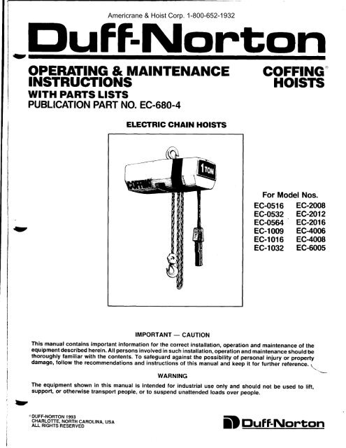
EL<strong>EC</strong>TRIC CHAIN HOISTS<br />
IMPORTANT - CAUTION<br />
This manual contains important information for the correct installation, operation and maintenance of the<br />
equipment described herein. All persons involved in such installation, operation and maintenance should be<br />
thoroughly familiar with the contents. To safeguard against the possibility of personal injury or property<br />
damage, follow the recommendations and instructioni of this manuat anci feep it for furthei reference. 1<br />
WARNING<br />
The equipment shown in this manual is intended for industrial use only and should not be used to lift,<br />
support, or otherwise transport people, or to suspend unattended toads over people.<br />
"TOUFF-NORTON 1993<br />
g|rlE L_q'!f_E,_NORTH CA ROL| NA, U SA<br />
ALL RIGHTS RESERVED<br />
COFFING"<br />
HOTSTS<br />
For Model Nos.<br />
<strong>EC</strong>-0516 <strong>EC</strong>-2008<br />
<strong>EC</strong>-0s32 <strong>EC</strong>-2012<br />
<strong>EC</strong>-0564 <strong>EC</strong>-2016<br />
<strong>EC</strong>-l009 <strong>EC</strong>-4006<br />
<strong>EC</strong>-l016 <strong>EC</strong>-4008<br />
<strong>EC</strong>-l032 <strong>EC</strong>-6005<br />
Duft-Nonton
S<strong>EC</strong>TION I<br />
t-l<br />
1l<br />
l_3<br />
l-4<br />
l-5<br />
t_6<br />
S<strong>EC</strong>TION II<br />
tl<br />
2-t<br />
2-4<br />
2-5<br />
2-6<br />
a1<br />
2-8<br />
S<strong>EC</strong>TION III<br />
3-l<br />
t-z<br />
J-J<br />
3-4<br />
S<strong>EC</strong>TION IV<br />
+l<br />
+2<br />
+t<br />
u<br />
+5<br />
+6<br />
S<strong>EC</strong>TION V<br />
5-l<br />
5-2<br />
5-3<br />
5-4<br />
5-5<br />
5-6<br />
S<strong>EC</strong>TION VI<br />
6-l<br />
S<strong>EC</strong>TION VII<br />
7-l<br />
11<br />
S<strong>EC</strong>TION VIII<br />
8-l<br />
8-2<br />
8-3<br />
FIGURE 8-I<br />
FIGURE 8.2<br />
FIGURE 8.3A<br />
RGURE 8-38<br />
FICURE 8-4A<br />
RGURE 84B<br />
FIGURE 8.5<br />
FIGURE 8-6<br />
FIGURE 8-7A<br />
FIGURE 8-7B<br />
FIGURE 8-7C<br />
FIGURE 8.7D<br />
FIGURE 8-8A<br />
FIGURE 8.88<br />
FIGURE 8.9<br />
FIGURE 8.IOA<br />
FIGURE 8.IOB<br />
RGURE 8-II<br />
S<strong>EC</strong>TION IX<br />
Americrane & <strong>Hoist</strong> Corp. 1-800-652-1932<br />
rABLE OF CONTENTS<br />
INTRODUCTION<br />
General Information<br />
SafetySrandards .... ..<br />
<strong>Hoist</strong> Construction and Features . . . . . .<br />
Basic <strong>Hoist</strong> Data . .<br />
Applicarion Information<br />
Warranty.......<br />
INSTALLATION<br />
Safety Notes<br />
Hanging the <strong>Hoist</strong><br />
Power Supply Connection<br />
Vent Plug .. .<br />
Chain Lubrication . . . ..<br />
Testing .<br />
Trolley lnstallation. . . .<br />
ChainContainerlnstallation ....<br />
OPERATION<br />
General<br />
Safety Notes<br />
Handling The Load<br />
Overload Limiting Prorection .<br />
INSP<strong>EC</strong>TION<br />
General<br />
Frequent Inspection<br />
Periodic Inspection<br />
[.oad Brake Function Check .<br />
Chain Inspecrion<br />
Hook Throal Opening<br />
MAINTENANCE AND REPAIR<br />
General<br />
Limit Switch Adjustment . . .<br />
Motor Brake Adjustment<br />
Top Suspension Removal and Replacement . . . . .<br />
Chain Replacement<br />
Lubrication<br />
TROUBLESHOOTING<br />
General<br />
WIRING<br />
Voltage Conversion<br />
WiringDiagrams......<br />
ILLUSTRATED PARTS LISTS<br />
General<br />
How to Use lhe Parls List. .<br />
How to Order Replacement <strong>Parts</strong> . .<br />
Basic <strong>Hoist</strong><br />
Suspension Assembly Kits<br />
Motor <strong>Parts</strong> (Three Phase) . . .<br />
Motor Pans (Single Phase)<br />
Controller Area (SinSle Speed)<br />
Controllcr Area (Two Speed)<br />
Transmission.....<br />
Chaining<strong>Parts</strong>...<br />
Bottom Block (th & t/z-ton) . . .<br />
Botrom Block(l-ton). .... . . .<br />
Bottom Block (Double Chain) .<br />
Bottom Block (Triple Chain)<br />
Standard Limit Switcb Pans.<br />
Long Lift Limir Switch <strong>Parts</strong> . .<br />
Motor Brake <strong>Parts</strong> . . .<br />
Pushbutton (Single Speed <strong>Hoist</strong>)<br />
Pushbutton (Two Speed <strong>Hoist</strong>).<br />
Chain Container <strong>Parts</strong>. . . . . .<br />
DO'S AND DO NOT'S<br />
PAGE<br />
...7<br />
7<br />
....7<br />
9<br />
9- l0<br />
l0<br />
...t0<br />
lG.ll<br />
...11<br />
ll<br />
...12<br />
t2-t3<br />
l+15<br />
l*<br />
3 5<br />
J<br />
J<br />
.4<br />
..4<br />
..4<br />
..4<br />
.4<br />
4<br />
+5<br />
.6<br />
6<br />
6<br />
6<br />
7<br />
l6<br />
l6-18<br />
.19<br />
.19<br />
l9<br />
.20<br />
J1<br />
.24<br />
.25<br />
26<br />
.27<br />
.28<br />
.30<br />
.32<br />
32<br />
.32<br />
.32<br />
.34<br />
.35<br />
.J6<br />
.38<br />
40<br />
.42<br />
43<br />
3<br />
*'
U<br />
1-1. General Information<br />
This manual provides information for the safe operation<br />
and maintenance of <strong>Coffing</strong>o <strong>EC</strong>-l <strong>Series</strong> <strong><strong>Hoist</strong>s</strong>. All<br />
persons operating or maintaining these hoists should be<br />
familiar with the information contained herein. Adherence<br />
to the precautions, procedures, and maintenance<br />
practices described should ensure long reliable operation.<br />
Suggestions for improvements to this manual are<br />
solicited.<br />
1-2. Safety Standards<br />
All persons concerned with the installation, operation,<br />
inspection and maintenance of these hoists are urged to<br />
read American National Standard (ANSI) B30.16. That<br />
Standard contains valuable guidelines concerning practices<br />
designed to minimize hazards associated with the<br />
use of overhead hoisting equipment. ANSI B30.16 also<br />
contains detailed procedures for establishing hoist<br />
inspection and maintenance programs and can be of<br />
significant assistance in maintaining compliance with<br />
OSHA regulations.<br />
1-3. <strong>Hoist</strong> Construction and Features<br />
Strong, lightweight aluminum alloy die castings provide<br />
a compact, protective enclosure for the mechanical and<br />
clcctrical components of Coffrng' <strong>EC</strong>-l <strong>Series</strong> <strong><strong>Hoist</strong>s</strong>.<br />
Heal treated alloy steel gearing operates in an oil bath<br />
1o provide the most reliable lubrication and eflective<br />
heat dissipation.<br />
<strong>EC</strong>-l <strong>Series</strong> <strong><strong>Hoist</strong>s</strong> incorporate the following<br />
features:<br />
a. Overload limiting clutch.<br />
b. Completely independent mechanical and electrical<br />
brakes.<br />
c. Adjustable limit swilches.<br />
d. Tough, nylon weatherproof pushbulton stations.<br />
e. Steel strain cable inside pushbutton cord.<br />
f. Transformer isolated, low-voltage pushbutton<br />
controls.<br />
g. Quick voltage conversion on dual-voltage units.<br />
TABLE 1-1. BASIC HOIST DATA<br />
Model<br />
No.<br />
<strong>EC</strong>-0516<br />
<strong>EC</strong>4532<br />
8C4564<br />
<strong>EC</strong>-1009<br />
<strong>EC</strong>-1016<br />
<strong>EC</strong>-1032<br />
<strong>EC</strong>-2008<br />
<strong>EC</strong>-2012<br />
<strong>EC</strong>-2016<br />
<strong>EC</strong>4006<br />
<strong>EC</strong>4008<br />
Rrted<br />
Irad<br />
0b)<br />
500<br />
500<br />
500<br />
r000<br />
1000<br />
1000<br />
2000<br />
2000<br />
2000<br />
4000<br />
4000<br />
Americrane & <strong>Hoist</strong> Corp. 1-800-652-1932<br />
sEcfloN I<br />
INTRODUCTION<br />
l,ift Speed<br />
et Reted l-oed<br />
(ft per min)<br />
l6<br />
64<br />
9<br />
l6<br />
32<br />
8<br />
t2<br />
l6<br />
Motor<br />
HP<br />
Vt<br />
Ut<br />
I<br />
Vt<br />
y2<br />
I<br />
Vt<br />
th<br />
6<br />
8 I<br />
<strong>EC</strong>-6005 60m ) I<br />
1-4. Basic <strong>Hoist</strong> Data<br />
The basic hoist models covered bv this manual are listed<br />
in Table l-1.<br />
I<br />
1-5. Application Informataon<br />
This hoist is intended for general industrial use in the<br />
lifting and transporting of freely suspended material<br />
loads within its rated load. Prior to installation and<br />
operation, the user should review his application for<br />
abnormal environmental or handling conditions and to<br />
observe the applicable recommendations as follows:<br />
a. Adverse Environmental Conditions Do not use the<br />
hoist in areas containing flammable vapors, liquids,<br />
gases or any combustible dusts or fibers. Refer to<br />
Article 500 of The National Electric Code. Do not<br />
use this hoist in highly corrosive, abrasive or wet<br />
environments. Do not use this hoist in applications<br />
involving extended exposure to ambient temperatures<br />
below -10"F or above 130"8<br />
b. Lifting of Hazardous Loads This hoist is not recommended<br />
for use in lifting or transporting hazardous<br />
loads or materials which could cause wide-spread<br />
damage if dropped. The lifting of loads which could<br />
explode or create chemical or radioactive contamination<br />
if dropped requires fail-safe redundant supporting<br />
devices which are not incorporated into this hoist.<br />
c. Lifting of Guided l-oads This hoist is not recommended<br />
for use in the lifting ofguided loads, including<br />
dumbwaiters and non-riding elevators. Such applications<br />
require additional proteclive devices which are<br />
not incorporated into this hoist. Refer to your stale<br />
and local regulations governing the requirements for<br />
clevator and dumbwaiter installations.<br />
1-6. Warranty<br />
Every hoist is thoroughly inspected and tested prior to<br />
shipment from the lactory. Should any problerns develop.<br />
return the complete hoist prepaid to your nearest Dufl'-<br />
Norton Authorized Warranty Repair Station. lf inspection<br />
reveals that the problem is caused by clefective workntanship<br />
or material , repairs will be made without charge and<br />
the hoist will be returned, transportatic'rn prepaid.<br />
This warranty does not apply where: ( I ) deterioration is<br />
caused by normal wear, abuse, improper or inadequate<br />
power supply, eccentric or side loading, overloading.<br />
chernical or abrasive actions. improper rnaintenance or<br />
excessive heat; (2) problems resulted from repairs, modifications<br />
or alterations made by persons other than factory<br />
or Duff-Norton Authorized Warranty Repair Station personnel;<br />
(3) the hoist has been abused or damaged as a<br />
result of an accident; (4) repair parts or accessories other<br />
than those supplied by Duff-Norton are used on the hoist.<br />
Equipment and accessories not of the seller's manufacture<br />
are warranted only to the extent that they are warranted by<br />
the manufacturer. EXCEPT AS S]'ATED HEREIN.<br />
DUFF-NORTON MAKES NO OTHER WARRAN-<br />
TIES, EXPRESS OR IMPLIED, INCLUDING<br />
WARRANTIES OF MERCHANTABILITY AND<br />
FITNESS FOR A PARTICULAR PURPOSE.
2-1. Salety Notes<br />
a. Inspect the hoist for any evidence of shipping damage<br />
or loose parts.<br />
b. The supporting structure and load attaching devices<br />
should have a load rating at least equal to that of the<br />
hois1.<br />
c. This hoist is not suitable for use in uncovered ouldoor<br />
locations or areas containing explosive dust, vapors<br />
or gases.<br />
d. The installation area must provide safe operating<br />
conditions for the operator, including sufficient room<br />
for the operator and other personnel to stand clear<br />
of the load at all times.<br />
e. In areas where slack chain hanging from the hoist<br />
may create a hazard, use a chain container (see Figure<br />
2-2).<br />
2-2. Hanging the <strong>Hoist</strong><br />
Hook mounted hoists can be used with a variety of<br />
trollcys or stationary hangers. It is recommended that a<br />
hand-geared or motorized trollcy be used when the<br />
pulling effort required to move thc hoist exceeds 100<br />
pounds or when the application rcquires frequent movemcnt<br />
of the hoist.<br />
a. Makc sure thal thc- hook latch closes after hanging<br />
thc hoist.<br />
b. The standard top hook is restrained from rotation by<br />
a plate and two screws. Thc hook can be madc lo<br />
swivel frecly by removing the plate, or can be rotated<br />
90" and fixed in that position.<br />
c. Sce Figure 2-l for instructions on adjusting lugmounted<br />
plain trolleys.<br />
d. Refer to Coffrng Motorized Trolley Operating and<br />
Maintenance Instructions manual for motorized trollcy<br />
installation instructions.<br />
2-3. Power Supply Connection<br />
a. Disconnect power before making connections.<br />
b. Voltage supplied to the hoist should be within plus<br />
or minus 100/o of the voltage specified for the hoist.<br />
Hoisls are lagged at the factory with a tag indicating<br />
the vohage for which the hoist is wired. Standard<br />
single phase hoists are convertible from ll5 to 230<br />
volts. Standard single speed. three phase hoists are<br />
convertible from 460 volts to 230 volts. See the<br />
Wiring section (paragraph 7-l) for voltage conversion<br />
instructions.<br />
c. National ElectricalCode (ANSI Cl) and local electrical<br />
codes should be consulted and proper disconnects,<br />
branch circuit protectors, and wiring provided.<br />
d. Power cables furnished with the hoist have a green<br />
colored ground wire which must be securely connected<br />
to the electrical system ground.<br />
Americrane & <strong>Hoist</strong> Corp. 1-800-652-1932<br />
sEcroN il<br />
INSTALLATION<br />
e. When installing a three-phase hoist, make only temporary<br />
connections at the power line. Push the "UP"<br />
button and observe the direction of the hook. If it<br />
raises, the phasing is correct and permanent connections<br />
may be made at the power line. If the load block<br />
lowers when the "UP" button is pushed, release the<br />
button immediately since the limit switches will not<br />
operate to protect the hoist from over-travel. Reverse<br />
the red and black wires at the power line connection<br />
to correct the hook direction.<br />
CAUTION<br />
Do not change connections in the hoist or the pushbutton<br />
assembly.<br />
2-4. Vent Plug<br />
This hoist has an oil-bath transmission. For shipping<br />
purposes, a non-vented fill plug (24, Figure 8-l) was<br />
installed at the factory. A vented plug is located in an<br />
envelope tied to one of the hoist cnd covers and must<br />
be installed in place of the non-vented shipping plug<br />
before operating the hoist.<br />
2-5. Chain Lubrication<br />
Thc hoist chain should bc liberally oiled before placing<br />
thc hoist inlo operation. For lubrication instructions,<br />
scc paragraph 5-6.a.<br />
2-6. Testing<br />
a. Bcfore placing the hoist into operation, check for<br />
proper limit switch operation. Push the "UP" butlon<br />
and verify that the hook block stops at least 2 inches<br />
from the botlom of the hoist. Run the hoist down to<br />
ils lower limit. At least l2links ofchain should remain<br />
on the slack end. If either switch is not correcl, adjusl<br />
according to the procedure outlined in paragraph 5-2.<br />
NOTE<br />
The upper and lower limit switches are factory set to<br />
provide the maximum allowable hook travel. This<br />
travel adjustment should not be increased. Howcver,<br />
the switches may be adjusted to stop the hook sooner<br />
at either end of its travel.<br />
b. Attach a light load to the hook and check the hoist<br />
for proper operation. The load should slop without<br />
noticeable drift when the pushbutton is released.<br />
Increase the load to near rated load. The hoist should<br />
still lifl the load without hesitation and stop with no<br />
more than one inch drift.<br />
2-7 . Trolley Installation<br />
Cofling'CT <strong>Series</strong> trolleys can be mounled on American<br />
Standard I Beams from 6 to l8 inches high. Adjustment<br />
for di{Ierent beam dimensions is accomplished with thft:proper<br />
placement of spacer washers as described below<br />
in paragraph 2-7.a.
a. "I"-Beam Adjustment. Adjustment for "I" beam sizes<br />
and tolerances is accomplished by locating the spacer<br />
washers as shown in Figure 2-1. Normal placement<br />
of washers is given in Table 2-2. Refer to Table 2-l<br />
for identification of part names and numbers.<br />
BEAM MANUFACTURING TOLERANCES<br />
ALLOW WIDE VARIATIONS FROM HAND-<br />
BOOK FLANGE WIDTHS, AND SLIGHT<br />
CHANGES TO R<strong>EC</strong>OMMENDED WASHER DIS-<br />
TRIBUTION MAY BE N<strong>EC</strong>ESSARY TO SUIT<br />
SP<strong>EC</strong>IFIC INSTALLATIONS.<br />
DETAIL<br />
3-TON CT TROLLEY<br />
WHEEL ASSEiIBLY<br />
TABLE 2-1. PARTS LIST FOR CT TROLLEY<br />
INDEX PART PART NUMBERS<br />
NO. NAME % TO 2-TON 3-TON<br />
t<br />
z<br />
3<br />
4<br />
5<br />
6<br />
7<br />
Load Pin<br />
Washer (7r" Thick)<br />
Washer (.135" Thick)<br />
Washer (.075' Thick)<br />
Nut<br />
Side Plate<br />
Wheel<br />
r03Kl<br />
H-42t1<br />
H-4209<br />
H-42r0<br />
H-3945<br />
5Kl<br />
45Kl<br />
t03Kt<br />
H-42t1<br />
H-4209<br />
H-4210<br />
H-3945<br />
5K2<br />
45K2<br />
The particular beam on which your hoist is to be<br />
installed should be measured and trolley spacerwashers<br />
adjusted as required to achieve a clearance of ln"<br />
to t/s".<br />
b. Periodic Inspection. The trolley should be inspected<br />
periodically for evidence of excess wear or overload.<br />
<strong>Parts</strong> should be replaced as required.<br />
c. Lubrication. Trolley wheels are equipped with sealed,<br />
lifetime lubricated, precision ball bearings which<br />
should not require lubrication for the normal service<br />
of the trolley.<br />
f<br />
\<br />
t1<br />
I<br />
I<br />
FIGURE 2-I. COFFING CT TROLLEY<br />
TABLE 2-2. TROLLEY I-BEAM ADJUSTMENT DATA<br />
tAmenan<br />
l-Beam'<br />
Si"r &<br />
Weight<br />
6"-t2.5 #<br />
6-t7.25#<br />
8"- I 8.4<br />
8"-23.0<br />
0'-25.4 #<br />
0'-35.0 #<br />
2',-31.8 #<br />
2"-35.0 #<br />
5'42.9 #<br />
5',-50.0 #<br />
8',-54.7 #<br />
8"-70.0 #<br />
Srandard I-B€am<br />
F-lange<br />
width<br />
1.330<br />
3.565<br />
4.000<br />
4.t7<br />
|<br />
4.660<br />
4.944<br />
5.000<br />
5.078<br />
J.500<br />
5.640<br />
6.000<br />
6.250<br />
NOTE: All dimensions are in inchx unl6s otheryiF smificd.<br />
Americrane & <strong>Hoist</strong> Corp. 1-800-652-1932<br />
Foint A<br />
Wsshers Between<br />
Susp. Lug & Sleeve<br />
INDEX<br />
NO.<br />
8<br />
9<br />
0<br />
I<br />
2<br />
3<br />
4<br />
1a<br />
PART<br />
NAME<br />
Axle<br />
Retaining Ring<br />
Bearing<br />
Retaining Ring<br />
Nut (Axle)<br />
Washer<br />
Spacer<br />
Foint B<br />
Weshers Between<br />
Sideplete & Nut<br />
.135 Thicli .075 Thick .135 Thick .075 Thick<br />
I<br />
2<br />
6 7<br />
5<br />
7<br />
9 9<br />
0<br />
0<br />
I<br />
2<br />
0<br />
0<br />
8<br />
9 5<br />
8<br />
7<br />
6<br />
6<br />
4<br />
I 2<br />
0 I<br />
J<br />
z<br />
0<br />
0<br />
I<br />
0<br />
5<br />
5<br />
4<br />
J<br />
5<br />
5<br />
I<br />
4<br />
5<br />
4<br />
0<br />
0<br />
PART NUMBERS<br />
% TO 2-TON 3-TON<br />
l02Kl t02K2<br />
Not Req. H-5530<br />
500K4 500K5<br />
H-5528<br />
H-3945<br />
H-5529<br />
H-3946<br />
H-42t1<br />
200Kr<br />
H-42t2<br />
Not Req.<br />
Acturl<br />
Sprcing<br />
Susp. Lug<br />
to Sleeve<br />
.135<br />
.2"1o<br />
.480<br />
.555<br />
.8t0<br />
.945<br />
.965<br />
1.021<br />
t.215<br />
1.290<br />
1.460<br />
l.590<br />
hintC<br />
Cleennce<br />
Wheel to<br />
Berm<br />
l5<br />
J)<br />
25<br />
l5<br />
25<br />
l8<br />
l0<br />
26<br />
l0<br />
l5<br />
-tQ7<br />
.lil
2-8. Ghain Container Installation<br />
a. Operate hoist in "down" direction until it is stopped<br />
by the limit switch. Disconnect the slack end of the<br />
chain from the hoist by using a small screwdriver to<br />
slide the spring-loaded pin to the left. At least 8 inches<br />
of chain should hang from the hoist. If less than 8<br />
inches of slack chain is present, readjust lower limit<br />
switch using the procedures<br />
detailed in paragraph 5-2.<br />
b. Slide the spring-loaded pin aside and slip the mounting<br />
arm into the slot until the pin fits through the<br />
hole in the plate (see Figure 2-2). Be sure pin passes<br />
CHAIN<br />
CoNTAINER--\<br />
$<br />
CAUTION \ \<br />
Short edge of chain container \<br />
bodv must be mounted \<br />
toward hoist (as shown).<br />
3-1. General<br />
This section presents information concerning the proper<br />
operation of the Cofling'Electric Chain <strong>Hoist</strong>. It is not<br />
intended to serve as a handbook on rigging. Rigging, the<br />
process of moving heavy loads using mechanical<br />
devices, requires special knowledge and equipment. For<br />
information on the safe use of slings and similar riggrng<br />
gear, users are urged to consult a textbook on rigging.<br />
3-2. Safety Notes<br />
a. Inspect the hoist for any sign of loose, broken, or<br />
malfunctioning parts (see Section IV). Any malfunctioning<br />
hoist should be tagged as "out oforder" and<br />
removed from service until the defect is corrected.<br />
b. Before starting the hoist, the operator should be<br />
certain that all personnel are clear.<br />
c. Do not lift more than the rated load of the hoist.<br />
d. Do not lift people or loads over people.<br />
e. Avoid joggrng controls or quick reversals of suspended<br />
loads.<br />
f Do not leave a suspended load unattended.<br />
g. The operator should have a clear view of the load<br />
Americrane & <strong>Hoist</strong> Corp. 1-800-652-1932<br />
FIGURE 2-2. CHAIN CONTAINER INSTALLATION<br />
c.<br />
d.<br />
e.<br />
sEcTtoN ill<br />
OPERATION<br />
completely through plate and into the opposite<br />
housing.<br />
Use the two hex washer head screws provided to<br />
fasten the two remaining hanger chains into the I<br />
notches on the lower edgei of tne hoist housings. e<br />
Be sure the end of the chain is started into the<br />
container. Run hoist up until the hook block is even<br />
with the bottom of the chain container.<br />
Reset upper limit switch at this position (see procedure,<br />
paragraph 5-2) to prevent the possibility of<br />
raising a load into the chain container.<br />
SLOT FOR<br />
SMALL SCREWDRIVER<br />
HEX HEAO<br />
anytime it is moving and should be sure that the<br />
load does not contact any obstructions.<br />
h. Read ANSI 830.16 Safety Standard for Overhead<br />
<strong><strong>Hoist</strong>s</strong>.<br />
3-3. Handling The Load<br />
a. Align hoist directly over load. Avoid side pull.<br />
b. The hoist chain should not be wrapped around the<br />
load. Use proper slings.<br />
c. Be sure there are no twists in the load chain as it<br />
enters the hoist.<br />
CAUTION<br />
This condition should be constantly checked on double<br />
or triple chain hoists because it is possible for<br />
the load block to be "capsized" or flipped over one<br />
or more times, putting twist in the chain. The presence<br />
of twist may not be obvious when the hook block<br />
is in the lowered position but can cause serious chain<br />
binding when the hook block is in its fully raised<br />
position.<br />
d. Bring the hook into engagement with the load and<br />
make sure it is well seated before proceeding to lift<br />
b"
{y<br />
the load. On multiple reeved hoists, be sure that the<br />
load is equalized on all supporting chains.<br />
e. Lift the load just clear of its supports and stop the<br />
hoist to check for proper brake operation.<br />
f. Avoid letting the hook or load swing excessively<br />
while moving a trolley suspended hoist.<br />
3-4. Overload Limiting Protection<br />
This hoist is equipped with a factory-calibrated overload<br />
limiting clutch, which will permit the lifting of loads<br />
within its load rating, but will prevent the lifting of<br />
damaging overloads while the hoist is being operated.<br />
If the load being lifted exceeds the lifting capability of<br />
the overload clutch, the hoist motor will continue to<br />
4-1. General<br />
A scheduled inspection routine should be established<br />
for this hoist based upon severity of use and environmental<br />
conditions. Some inspections should be made<br />
frequently (daily to monthly) and others periodically<br />
(monthly to yearly). It is suggested that an Inspection<br />
and Maintenance Check List and an Inspector's Report<br />
similar to those shown in Figures 4-l and 4-2 be used<br />
and filed for reference. All inspections should be made<br />
by a designated inspector. Special inspections should be<br />
4 made after any significant repairs or any situation causlD<br />
ing suspicion thal the hoist may have been damaged.<br />
Any hoist which has been removed from service for an<br />
extended time should receive an inspection as described<br />
under Periodic Inspections. ANSI B30.16, Safety Standard<br />
for Overhead <strong><strong>Hoist</strong>s</strong>, provides guidelines for hoist<br />
operation and inspection.<br />
V<br />
CAUTION<br />
Any unsafe condition disclosed by any inspection must<br />
be corrected before operation of the hoist is resumed.<br />
4-2. Frequent Inspection<br />
a. Check pushbutton station, brake, and limit switches<br />
for proper operation.<br />
b. Check hooks for deformation, chemical damage, or<br />
cracks. Bent hooks or hooks damaged from chemicals,<br />
deformation, cracks, or having excessive throat<br />
opening (see paragraph 4-6) should be replaced.<br />
Visible deformation of any hook may be evidence<br />
of hoist abuse and overloading and indicates that a<br />
thorough inspection of the complete hoist should be<br />
made.<br />
c. Check that bottom hook swivels freely.<br />
d. Check for missing, bent or otherwise damaged hook<br />
latches.<br />
e. Check pushbutton and power cord for cuts or other<br />
damage.<br />
4-3. Periodic Inspection<br />
The exact period for the following inspections will<br />
Americrane & <strong>Hoist</strong> Corp. 1-800-652-1932<br />
sEcTroN rv<br />
run, causing overheating of both the clutch and the<br />
motor. This condition should be avoided by immediately<br />
releasing the "[JP" button and reducing the load<br />
to within the hoist load rating.<br />
CAUTION<br />
The overload limiting clutch is an emergency protective<br />
device and should not be used to measure the maximum<br />
load to be lifted, or to sense the overload imposed by a<br />
constrained load. Manufacturing tolerances require that<br />
the clutch be set somewhat above the load rating of the<br />
hoist. The fact that the hoist will pick up loads in excess<br />
of its load rating does not in any way sanction the use<br />
of the hoist in an overloaded condition.<br />
INSP<strong>EC</strong>TION<br />
depend on the anticipated severity ofhoist use. Determination<br />
of this period should be based on the user's<br />
experience. It is recommended that the user begin with<br />
a monthly inspection and extend the periods to quarterly,<br />
semi-annually, or annually, based on his monthly<br />
inspection experience.<br />
a. Clean hoist of any dirt or foreign material. Inspect<br />
bottom block for accumulation of debns.<br />
b. Perform all frequent inspections listed above.<br />
c. Check for loose bolts, screws and nuts.<br />
d. Check housings, load block, and other parts for wear,<br />
corrosion, cracks or distortion. Check for abnormal<br />
openings between housing sections.<br />
e. Check motorbrake forworn discs, oil contamination<br />
or excessive clearance (see paragraph 5-3).<br />
f. Check mechanical load brake function (see Figure<br />
4_3).<br />
g. Inspect the entire length ofchain for gouges, nicks,<br />
weld spatter, corrosion, distortion and wear. See<br />
CHAIN INSP<strong>EC</strong>TION, paragraph 4-5.<br />
h. Inspect hooks and suspension parts for cracks, distortion<br />
or extreme wear.<br />
i. Inspect hooks for cracks using magnetic particle, dye<br />
penetrant or other crack detecting methods.<br />
j. Check limit switch set points and resel if necessary<br />
(see paragraph 5-2).<br />
k. Inspect all wiring for defective insulation, and check<br />
to be sure all electrical connections are tight. Check<br />
motor reversing contactor or relay for burned<br />
contacts.<br />
l. Inspect for oil leaks. Check oil level.<br />
m. Inspect for missing or illegible capacity or warning<br />
labels.<br />
n. Inspect the supporting structure for continued ability<br />
to support the hoist rated load.
INSP<strong>EC</strong>TION & MAINTENANCE CH<strong>EC</strong>K LIST<br />
EL<strong>EC</strong>TRIC POWERED OVERHEAD CHAIN HOIST<br />
Type ol Horsl Capacrty (Tons;<br />
Localron Orgrnal lnstallatron Oate<br />
lvlanuf actu rer<br />
FREOUENCY OF INSP<strong>EC</strong>TION :<br />
Americrane & <strong>Hoist</strong> Corp. 1-800-652-1932<br />
Manuf acturer s Ser al No<br />
Frequencv ol lnsDeclron<br />
Item<br />
Frequent Periodrc<br />
Possrble Delrcrenoes ff<br />
Darlv MonthlV112Mo<br />
Operatrng Controls a a o Any def rcrency causrnq rmproper operatro'l<br />
Lrmrt Swrtches a a o<br />
a<br />
Any def rcrency causrng rmproper operatron<br />
Pitlinq or delerloralton<br />
Drsc (Motor) Brake o a a Slippage or excessive wear<br />
a Glazino. contamrnatron or excessive wear<br />
Load Brake<br />
o Farlure to support load wrth drsc brake open<br />
{Mechanrcal)<br />
(see paragraph 4-3 f)<br />
Hooks a a a Excessrve throat openrng, bent or twrsted .nore than<br />
1O degrees, damaged hook latch. wear. chemrcal<br />
damage, worn hook bearrng<br />
a Cracks (use dye penetrant. magnetrc panrole or<br />
other surtable detectron method)<br />
Suspensron Lug<br />
(rf used)<br />
a Cracks, excessrve wear or other damage whrch may<br />
rmparr the strength of the lug<br />
a Cracks (use dye penetrant, magnelrc parlrcle or<br />
other surtable detection method)<br />
Charn o o a Inadequate Iubflcation, excessrve wear or strelch<br />
cracked, damaged or twlsted lrnks, corrosron or<br />
forerqn substance<br />
Hook and Suspensron<br />
a Cracks, bendrng, str pped lhreads loose mountrng<br />
Luo Connections<br />
screws<br />
Pins, Bearings.<br />
Eushings. Shatts<br />
Couplings, Charn<br />
Guides<br />
o Excessrve wear. corros on cracks distortron<br />
Nuts. Bolts. Rrvels a Looseness. slilpped and damaged lhreads<br />
corrosron<br />
Sheaves a Drstortron, cracks, and excessrve wear<br />
Build uo of foreron substances<br />
Housings, Load<br />
a Cracks drstortron excessive wear<br />
Elock<br />
Internal build uo of foreiqn subslances<br />
Wrrrno and Termrnals a Fravrno. deleclrve Insulatron<br />
Contact Block,<br />
Magnelrc Horst<br />
Conlrol Swrtch, Othef<br />
Electrrcal Aoparatus<br />
o Loose conneclrons, burned or pttted contacts<br />
Supporting Structure<br />
and TrolleV (if used)<br />
a Damage or wear whlch restilcts abllrty to support<br />
rmposed loads<br />
Nameplates, Decals,<br />
Warninq Labels<br />
a Missrng, damaged or rllegible<br />
Transmissron<br />
Lubricant<br />
a Low Level, Requrres Changing<br />
NOTE: Reler to Marntenance and Inspectron Seclrons of lhe Horst Marntenance Manual lor further detarls<br />
Frequent - Indrcales rtems requrrrng rnspeclrons darly to monthly Darly Inspeclrons may be perlormed by tne operalor rl<br />
properly desrgnated<br />
Perrodrc - Indicates items requrrrng Inspectron monthly to yearly Inspectrons to be performed by or under lhe drrectron of a<br />
properly desrgnated person The exact penod of Inspectron wrll depend on frequency and type of usage. Determrnation<br />
of this period will be based on the user's expenence. lt rs recommended that the user begrn wath a monthly<br />
inspection and extend the periods to quarterly, semi-annually or annually based on hrs monthly expertence.<br />
FIGURE 4-I. R<strong>EC</strong>OMMENDED INSP<strong>EC</strong>TIONAND<br />
MAINTENANCE CH<strong>EC</strong>K LIST<br />
8<br />
Actron<br />
Requ red<br />
u
!<br />
U<br />
INSP<strong>EC</strong>TOR'S REPORT<br />
ITEM REMARKS (L|ST DEFTCTENC|ES AND R<strong>EC</strong>OMMENDED ACTION)<br />
INSP<strong>EC</strong>TOR'S<br />
SIGNATURE<br />
DATE<br />
INSP<strong>EC</strong>TED APPROVEO BY DATE<br />
FIGURE 4-2. R<strong>EC</strong>OMMENDED INSP<strong>EC</strong>TOR'S REPORT.<br />
4-4. Load Brake Function Check<br />
To check the functioning of the mechanical load brake,<br />
proceed as follows:<br />
a. Attach a light load to the hoist and lift it several inches.<br />
b. DISCONN<strong>EC</strong>T HOIST FROM POWER SUPPLY<br />
and remove short end brake cover (see Figure 8-1,<br />
Index No. l).<br />
c. Refemng to Figure 4-3 (below) and Figure 8-9, place<br />
screwdrivers No. I and No. 2 behind the plate and<br />
arrnature assembly and prepare to pry against the<br />
transmission cover.<br />
NOTE<br />
Do not allow either screwdriver to contact brake disc<br />
(see Figure 8-9, Index No. 7).<br />
d. Carefully pry open motor brake (close solenoid gap)<br />
and observe action of load. If the load descends. the<br />
mechanical load brake is malfunctioning and must<br />
be repaired.<br />
4-5. Chain Inspection<br />
Chain inspection and lubrication are the most important<br />
aspects ofhoist maintenance. Removal ofthe chain from<br />
the hoisr usually is not necessary, but the chain should<br />
be run through the hoist enough that every link is made<br />
visible for inspection.<br />
a. Check each link forgouges, nicks, weld spatter, corrosion<br />
and distortion.<br />
Americrane & <strong>Hoist</strong> Corp. 1-800-652-1932<br />
>rl+-<br />
SCREWORIVER NO. 1<br />
TRANSMISSION COVER<br />
SCREWORIVER NO.2<br />
FIGURE 4-3. LOAD BRAKE FUNCTION CH<strong>EC</strong>K
. Inspect each link for wear to the diameter of the link<br />
(see Figure 4-4). The nominal link diameter is 0.250<br />
inch for chain on models up to <strong>EC</strong>-2008 and 0.281<br />
inch for models <strong>EC</strong>-2012 and above. If the diameter<br />
of any link of 0.250 chain is worn to less than 0.200,<br />
or the diameter of any link of 0.281 chain is worn to<br />
less than 0.225, the entire chain must be replaced.<br />
WEAR IN<br />
THESE AREAS<br />
FIGURE 4-4. TYPICAL WEAR ON LINKS<br />
Americrane & <strong>Hoist</strong> Corp. 1-800-652-1932<br />
l.) Check the chain for overall wear or stretch by<br />
selecting an unworn, unstretched length of chain (at<br />
the slack end, for example). Let the chain hang vertically<br />
with a light load (about 20lbs.)on rhe chain ro<br />
pull it taut. Use a large caliper 10 measure the outside<br />
length of a convenient number of links (about 12<br />
inches). Measure the same number of links in a<br />
used section of chain and calculate the percentage<br />
increase in length of the worn chain.<br />
2.) If the length of the worn chain is more than l7z0lo<br />
longer than the unused chain (.015" per inch of chain<br />
measured), then the chain should be replaced. If thc<br />
5-1. General<br />
This section provides instructions for the most common<br />
routine maintenance and adjustments. Major repairs are<br />
not within the scope of this manual and should be<br />
referred to qualified service facilities.<br />
SAFETY NOTE<br />
Always remove load and disconnect hoist from power<br />
suppll' before removing end covers or making repairs.<br />
5-2. Limit Switch Adjustment<br />
Limit switches are provided to protect the hoist<br />
against damage resulting from overtravel. For easy identification<br />
the upper (No. 2, Figure 5-l) and lower (No.<br />
3, Figure 5-l) limit switch adjusting nuts are colored red<br />
and green respectively. Each limit switch nut has ten<br />
slots for adjustment, and the increment of adjustment<br />
sEcTtoN v<br />
MAINTENANCE<br />
AND REPAIR<br />
10<br />
chain is worn less than l7:0/0, check it at several more<br />
places along its length. If any section is worn more<br />
than I t/zo/0, the chain should be replaced.<br />
d. The chain used in this hoist is accurately calibrated<br />
to operate over the load sprocket and is very carefully<br />
heat treated for maximum wear life and streneth.<br />
WARNING<br />
l. Do not weld or join hoist load chain.<br />
2. Do not substitute another manufacturer's chain in<br />
this hoist.<br />
3. Damage or wear, beyond the stated limits, to any<br />
portion of the chain requires that the entire length<br />
be replaced.<br />
4-6. Hook Throat Opening<br />
Use Table 4-l (below) to check hook throat opening.<br />
TABLE 4-1. MAXIMUM ALLOWABLE HOOK<br />
THROAT OPENING<br />
<strong>Hoist</strong> I-oad<br />
Reting<br />
(ton)<br />
t/q, t/t and I<br />
2<br />
3<br />
Top<br />
Hook'<br />
(in)<br />
l'/tt<br />
l'/rt<br />
lr%:<br />
Bottom<br />
Hoohr<br />
(in)<br />
l'/rt<br />
I 5/,0<br />
I ttln<br />
rFigu.es gru.n arc for hok wirh latch. Add r/ro' if mcasured withoui h@k latch<br />
FIGURE 5-I. LIMIT SWITCH ADJUSTMENT<br />
t<br />
u
iyr<br />
O<br />
is such that one slot is equivalent to one link of chain<br />
travel. Care should be exercised when adjusting either<br />
limit of travel. When a geared type limit switch is<br />
furnished (long lift hoists) each adjustment is equal to<br />
3 links of chain, or 30 links per revolution.<br />
a. Adjusting Upper Limit (Red Nut).<br />
l.) Carefully raise the load block to a point where its<br />
top is 2" or more from the hoist housing.<br />
2.) DISCONN<strong>EC</strong>T POWER from the hoist and<br />
remove the short end cover.<br />
3.) With a screwdriver, pry the spring guide plate (No.<br />
l, Figure 5-l) out of the slots in the colored limit<br />
switch nuts (Nos. 2 and 3).<br />
4.) Turn the slotted red nut (No. 2) toward its limit<br />
switch until the switch clicks.<br />
5.) Release the spring guide plate and be sure it snaps<br />
back into the slots in both nuts. Do not disturb the<br />
other slotted nut if is has been previously set.<br />
6.) Replace the short end cover and reconnect power<br />
to the hoist.<br />
7.) Carefully raise the load block to its upper limit<br />
and observe 10 see if it stops automatically at the<br />
desired point. Do not allow the load block to run into<br />
the hoist housing. The stopping point should be at<br />
least 2" below the hoist housing.<br />
b. Adjusting l,ower Limit (Green Nut)<br />
l.) Carefully lower the load block 1o a poinl where at<br />
least l2 links of slack chain hane down from the hoist<br />
housing.<br />
2.) DISCONN<strong>EC</strong>T POWER from the hoist and<br />
remove the short end cover.<br />
3.) Adjust the green limit switch nut in the same<br />
manner descnbed above for the red nut.<br />
4.) Replace the short end cover and reconnect power<br />
to the hoist.<br />
5.) Carefully lower the load block to its lower limit<br />
and observe if it stops automatically at the desired<br />
level. Do no1 run chain out of hoist or allow the slack<br />
end loop to become taut against the hoist housing.<br />
At least 12 links of slack chain should hane from the<br />
hoist.<br />
NOTE<br />
If upper and lower limits are not operating satisfactorily,<br />
repeat adjustment.<br />
5-3. Motor Brake Adiustment<br />
When properly adjusted, the multiple disc motor brake<br />
should release promptly, operate without noticeable<br />
chatter, and stop the load with no more than one inch<br />
of drift. If the hoist hesitates to lift the load promptly<br />
when the pushbutton is depressed, the brake should be<br />
adjusted per the following procedure.<br />
Americrane & <strong>Hoist</strong> Corp. 1-800-652-1932<br />
11<br />
Adjust to<br />
give .015" -.,<br />
oaD t<br />
T-<br />
FIGURE 5-2. MOTOR BRAKE ADJUSTMENT<br />
a. Remove any load and DISCONN<strong>EC</strong>T POWER<br />
liom hoist.<br />
b. Remove the short end cover.<br />
c. Rcferring to Figure 4-2, check the gap between arrnature<br />
(A) and frame (B). The correct gap is .015".<br />
d. Adjust the gap by turning the three lock nuts (F) and<br />
check with a feeler gauge to be sure the gap is the<br />
same on both ends of the solenoid.<br />
CAUTION<br />
Be sure the bottom of the armature does not touch<br />
the splined adapter (H). As wear occurs, the original<br />
clearance will be reduced. When this clearance<br />
is gone, THE BRAKE DISCS MUST BE RE-<br />
PLACED.<br />
e. Replace short end cover and reconnect power. Ifthe<br />
brake still chatters or is hesitant to release. refer to<br />
Section VI, Troubleshooting.<br />
5-4. Top Suspension Removal and Replacement<br />
A number of diflerent top suspension assemblies are<br />
available to accommodate different methods of hanging<br />
the hoist. Ifit should be necessary to change top suspensions,<br />
proceed as follows:<br />
a. DISCONN<strong>EC</strong>T POWER from hoist and move the<br />
hoist to a safe working area. If necessary, remove<br />
trolley and/or rotate suspension lug to gain access<br />
to the socket head cap screws bolting the top suspension<br />
yoke to the frame of the hoist.<br />
b. Remove socket head screws (1|rc" hex) and lift out<br />
the suspension assembly.<br />
c. Install new suspension assembly and tighten socket<br />
head screws to 75 ft-lbs torque.<br />
NOTE<br />
Due to the off-center hook or lug hole, the suspension<br />
yoke can be installed in the hoist in two different<br />
ways. With the hoist level, the hook or lug must<br />
always be directly over the bottom hook. Refer to<br />
Figure 5-4 for the proper yoke orientations for single,<br />
double and triple chain hoists.
L<br />
5-5. Chain Replacement (Old chain still in hoist)<br />
Refer to Figure 5-4, Chaining and Suspension Diagrams<br />
and proceed as follows:<br />
a. Run the load block up to its top limit.<br />
b. DISCONN<strong>EC</strong>T POWER from the hoist and remove<br />
the short end cover.<br />
c. With a screwdriver, push the spring guide plate (No.<br />
l, Figure 5-l) out of the slots in the plastic limit<br />
switch nuts. Turn the red slotted nut (2) back to<br />
about the center of the threaded screw. DO NOT<br />
DISCONN<strong>EC</strong>T THE WIRES FROM THE LIMIT<br />
SWITCHES.<br />
d. Remove the load hook assembly from the old chain.<br />
h.<br />
FIGURE 5-3. CHAINING HOIST<br />
Make a "C"-shaped chain link by grinding through<br />
one side of the end link of either the old or new<br />
chain. See Figure 5-3.<br />
Hook the special "C" link to the end link of both<br />
chains thus joining them. BE SURE the welds of the<br />
upstanding links of the new chain are out away from<br />
the load sheave. and that proper orientation is<br />
observed for attachment of the slack end in paragraph<br />
j. below.<br />
NOTE<br />
On triple chain hoists be sure all welds are aligned<br />
like the welds on the old chain. It may be necessary<br />
to cut a link from one or both ends of the chain to<br />
accomplish this.<br />
With the end cover o{I, connect the hoist to power<br />
supply. Be sure the gteen glound wire is properly<br />
grounded.<br />
Carefully jog the "lJP" button and run the joined<br />
pieces of chain into the hoist until about 12 inches<br />
of the new chain comes out the other side.<br />
DISCONN<strong>EC</strong>T POWER from the hoist.<br />
Remove both the "C" link and the old chain from<br />
the slack end pin (No. 28, Figure 8-6). This can be<br />
Americrane & <strong>Hoist</strong> Corp. 1-800-652-1932<br />
12<br />
k.<br />
L<br />
accomplished by depressing the pin against the slack<br />
end spring (29) with a small screwdriver. Remove<br />
the soft split link (23) from the old chain and attach<br />
the link to the new chain. Depress the slack end pin<br />
and install the split link observing proper orientation<br />
of the slack end of the chain when secured. Avoid<br />
twists in the chain.<br />
Adjust the lower limit switch per paragraph 5-2.b.<br />
Attach the bottom hook on single-chained hoists to<br />
the loose end ofthe chain. On double-chained hoists,<br />
feed the loose end of the chain through the load<br />
block (welds of the upstanding links will be in<br />
towards the sheave) and fasten the end ofthe chain<br />
to the dead end lug (No. 18, Figure 8-6).<br />
NOTE<br />
On triple chain hoists, feed the loose end ofthe chain<br />
through the load block (welds away from sheave),<br />
around the idler sheave in the hoist. and to the center<br />
of the load block.<br />
m. Adjust the upper limit switch per paragraph 5-2.a.<br />
n. Lubricate the new chain per paragraph 5-6.a and<br />
perform an operation test ofthe hoist.<br />
5-6. Lubrication<br />
Proper lubrication is necessary for long, trouble-free<br />
hoist operation. Refer to the following and to Table 5-1,<br />
Recommended Lubrication Schedule, for lubrication<br />
points, type of lubricant, and frequency of lubrication. 'lr.)<br />
a. Load Chain Clean the load chain with a non-acid and<br />
non-caustic solvent and coat with SAE 90 gear oil.<br />
Wipe excess oil to prevent dripping. If the hoist is<br />
used in an atmosphere containing abrasive dust, the<br />
chain should be cleaned and oiled more frequently.<br />
Never apply grease to the chain.<br />
b. Gearing The gear case of the hoist is filled at assembly<br />
with 46 oz. of a gear oil containing special frictionreducing<br />
additives.<br />
WARNING<br />
The use of gear oils other than that recommended in<br />
Table 5-l can cause brake chatter or can render the load<br />
brake incapable of holding a load. A 46 oz. container of<br />
this oil ls available from the Duff-Norton Co. (Part No.<br />
l4Jl).<br />
a. To check the oil level, remove the 7e" pipe plug from<br />
the side of the hoist. With the hoist hanging level,<br />
transmission oil should be even with the edge of the<br />
tapped plug hole.<br />
b. The length of time between necessary oil changes will<br />
depend on the severity of use the hoist receives. In<br />
general, the oil should be changed every 12 monlhs r<br />
of normal operation, or every 200 hours of actual 1,..1<br />
hoist on-time. Very heavy use or operation in high Y<br />
ambient temperatures (over 105'F) will require that<br />
oil be changed more often. An indication of the need<br />
t
I<br />
I<br />
l<br />
POWER<br />
CABLE<br />
for oil replacement is load brake noise. If an erratic<br />
tapping sound is made when lowering a load, the oil<br />
should be changed.<br />
c. Limit Switch Shaft To prevent rust, the threaded limit<br />
switch shaft should be given a light coat of grease or<br />
sprayed with a general purpose lubricant.<br />
d.<br />
OOUBLE CHAIN<br />
POWER CAELE<br />
END VIEW<br />
AS VIEWEO FROM<br />
END WITH SHORT<br />
COVER<br />
Idler Sheave Bearing (double and triple chain models<br />
only) Use a grease gun to put about a teaspoon of<br />
dust. etc., should be lubri€ted more freeucntly.<br />
NOTE POSITION<br />
OF SUSPENSION<br />
ASSEMBLY.<br />
FIGUR-E 5-4. CHAINING AND SUSPENSION DIAGRAMS<br />
grease through the grease fitting in the bottom block<br />
shaft. Avoid pumping an excessive amount of grease<br />
into the bottom block. On triple chain hoists, use a<br />
grease gun to lubncate the idler sheave in the hoist<br />
until fresh grease pumps from the end of the sheave<br />
bearing.<br />
e. Hook Bearing Apply a few drops of SAE 30 oil around<br />
the edge ofthe beanng.<br />
TABLE 5-1. R<strong>EC</strong>OMMENDED LUBRICATION SCHEDULE- MODEL <strong>EC</strong> EL<strong>EC</strong>TRIC CHAIN HOIST<br />
Figure And<br />
Index No.<br />
Component Type of Lubricanl<br />
Type of Service And<br />
Frequency of Lubrication<br />
Heavy Normal Infrequenl<br />
Frgure 8-6, No. 7 Ilad Chain SAE 90 Gear Oil Daily Weekly Monthly<br />
Figure 8-5 ueanng Coffrng No. H-7813 transmission<br />
oil (Kit No. l4J I<br />
contains quantity of oil<br />
Figure 8-8A, No. 9;<br />
Figure 8-8B, No. 7<br />
Figure 8-6, No. -<br />
&No.-<br />
Figure 8-2,<br />
Nos.t.3.4&5<br />
Figure 8-7C, No. I I<br />
Figure 8-7D, No. I I<br />
-imit Switch Shaft<br />
suflicient for one oil change).<br />
'WD-40" or general purpose<br />
spray lubricant.<br />
At periodic inspection (see Figure {1, paragraph 5-6-2\.<br />
Monthly Yearly Yearly<br />
-oad Hook Beanng SAE 30 Gear or Motor Oil WeekJy Monthly Yearly<br />
lop Hook or Susrnsion<br />
Lug Bearing<br />
iurfaces<br />
Idler Sheave<br />
Bearing (Bushing)<br />
Alt ercpt rdlcr b€ann8s<br />
Americrane & <strong>Hoist</strong> Corp. 1-800-652-1932<br />
SAE 30 Gear or Motor Oil Monthly Yearly Yearly<br />
NLGI #2 multi-purpose<br />
lithium base grease<br />
(Coffrne No. H-7610)<br />
13<br />
At periodic inspection (see Figure 4-l).
Americrane & <strong>Hoist</strong> Corp. 1-800-652-1932<br />
S<strong>EC</strong>TION VI<br />
TROUBLESHOOTING<br />
6-1. General electrician to do your repair work, we recommend that<br />
Use the following table as an aid to troubleshoot your you send your hoist to an approved service center for<br />
hoist. If you do not have an experienced machinist- repairs.<br />
Hook Fails To Stop At End Ol Travel.<br />
TROUBLE REMEDY<br />
I . Limit switches not operating. | 1. Check adjustment. See paragraph 5-2. Check connections against<br />
wiring diagram. Tighten loose connections or replace.<br />
2. Plastic limit switch nuts no1 moving on shaft. | 2. Check for stnpped threads or bent nut guide.<br />
3. Magnetic reversing switch malfunction. | 3. Remove electrical cover and check reversing switch<br />
<strong>Hoist</strong> Does Not Respond To Pushbutton.<br />
l. Power failure in supply lines.<br />
2. Wrong voltage or frequency.<br />
I l. Check circuit breakers, switches and connections in power<br />
I supply lines.<br />
I 2. Check voltage and frequency of power supply against the rating on<br />
the nameplate of the hoist.<br />
3. Improper connections in hoist or pushbutton<br />
station.<br />
4. Motor brake does not release.<br />
5. Faulty magnetic hoist conlrol switch.<br />
| 3. Check all connections at line conneclors and on terminal block.<br />
I Check terminal block on dual-voltage hoists for prop€r<br />
I voltage connections.<br />
| 4. Check connections to the solenoid coil. Check for open or short<br />
I circuit. Check for proper adjustment. See paragraph 5-3.<br />
| 5. Check coils for open or short circuit. Check all connections ln<br />
control circuit. Check for burned contacts. Replace as needed.<br />
Hook Does Not Stop Promptly.<br />
l. <strong>Hoist</strong> overloaded. I L Reduce load to within rated capacity of hoist.<br />
2. Brake not holding. | 2. Check motor brake adjustment (see paragraph 5-3) and load brake<br />
(figure 4-3).<br />
I l-<br />
Three-phase reversal.<br />
2. Improper connections.<br />
<strong>Hoist</strong> Hesitates To Lift When Energized.<br />
Hook Raises But Will Not Lower. (Motor not running)<br />
l. Reverse any two wires (except the green ground wire) at the power<br />
source (see paragraph 2-3).<br />
2. Check all connections against Wiring Diagram.<br />
l. <strong>Hoist</strong> overloaded. I l. Reduce load within rated capacity of hoist.<br />
2. Motor brake requires adjustmenl. I 2. Check motor brake adjustment, see Figure 5-3.<br />
3. Worn overload limiting clutch. | 3. Replace clutch.<br />
4. Low voltage. | 4. Check voltage at hoist power cord with hoist slarting. Voltage<br />
should be no less than 90% of volhge specified on hoist.<br />
5. Faulty SINPAC starting switch or start capacitor 15. Replace t-aulty component.<br />
(single phase hoists only).<br />
l. "Down" circuit open. I l. Check circuit for loose connections. Check "Down" limit switch<br />
for malfunction.<br />
2. Broken conductor in pushbutton cable. | 2. Check each conductor in the cable. Ifone is broken, replace<br />
entire cable.<br />
3. Faulty magnetic hoist control switch. | 3. Check coils for open or short circuit. Check all connections rn<br />
control circuit. Check for burned contacts. Replace as needed.<br />
14<br />
I<br />
,rl<br />
i<br />
( .1<br />
v
0<br />
TROUBLE REMEDY<br />
Hook Raises But Will Not Lower When Motor ls Operating.<br />
Consult Factory Or Authorized Duff-Norton Warranty Repair Station.<br />
Hook Lowers But Will Not Raise.<br />
L <strong>Hoist</strong> overloaded. I l. Reduce load to within rated capacity.<br />
2. Low voltage. | 2. Determine cause of low voltage and bring up to at least l0% of the<br />
voltage specified on hoist. Line voltage should be measured while<br />
holding or lifting load.<br />
3. "UP" circuit open. | 3. Check circuit for loose connections. Check "UP" limit switch for<br />
malfunction.<br />
4. Broken conductor in pushbutton cable. | 4. Check each conductor in the cable. lf one is broken, replace<br />
I entire cable.<br />
5. Faulty magnetic hoist control switch. | 5. Check coils for open or short circuit. Check all connections in<br />
control circuit.<br />
Check for burned contacts. Replace as needed.<br />
6. Faulty capacitor (single-phase hoists only). | 6. Check starting capacitor in motor. Replace if necessary.<br />
7. Worn overload limiting clutch. | 7. Replace clutch.<br />
l. Hoisl overloaded.<br />
2. Motor brake is dragging.<br />
3. Low voltage.<br />
4. Overload limiting clutch intermittently slipping.<br />
Brake "Noise". (Erratic<br />
Need transmission oil change or<br />
improper lubncant has been used.<br />
Load brake malfunctionrns.<br />
Motor Brake Noise Or Chatter. (While starting hoist)<br />
l. Brake needs adjustment<br />
2. Low voltage.<br />
Motor Brake "Buzz". (Anytime hoist is<br />
l. Brake needs adjustment.<br />
2. Broken shadine coil on brake framc.<br />
Americrane & <strong>Hoist</strong> Corp. 1-800-652-1932<br />
l. Reduce load to within rated capacity of hoist.<br />
2. Check for proper brake adj ustment or other defects. See paragraph 5- 3.<br />
3. Bring up voltage to plus or minus l0% of voltage specified on<br />
hoist. Line voltage should be measured while hoist is lifting load.<br />
4. Replace clutch.<br />
l. Change transmission oil. See Table 5-1.<br />
Note: <strong>Hoist</strong> Warranty is void if unapproved oil is used.<br />
2. Check load brake operation. See Figure 4-3<br />
l. Adjust as per parag.raph 5-3.<br />
2. Check voltage at hoist power cord with hoisr starting. Voltage<br />
should be no less than 90% of the voltage specified. I l5 volt hoists<br />
are particularly subject to voltage drop problems due to their high<br />
curent draw. Conversion to 230 volt operation is suggested in<br />
extreme cases.<br />
l. Adjust as per paragraph 5-3.<br />
2. Replace shading coil or complete brake frame assembl<br />
15
I<br />
Americrane & <strong>Hoist</strong> Corp. 1-800-652-1932<br />
sEcfloN vll<br />
Safety Notes<br />
Disconnect power from hoist before removing end covers.<br />
WIRING<br />
c. THREE PHASE HOISTS: Transfer leads T.1. T5. T6. T7.<br />
TU. T9. H2. H3. Sl. and S2 per the appropriate terminal<br />
block schematic.<br />
CAUTION<br />
Do not move any wires or make any changes to the<br />
wiring except at the terminal block.<br />
7-1. Voltage Conversion<br />
Standard singJe phase units are convertible from I l5 to<br />
230 volts and standard single speed three phase units<br />
are convertible from 460 to 230 volts. Conversion to<br />
d. After converting voltage, check for proper phasing of<br />
the alternate voltage can be accomplished with the fol-<br />
three phase units and check for proper limit switch<br />
lowing procedure.<br />
operation.<br />
a. Be sure power is disconnected from hoist. Remove<br />
long end cover.<br />
7-2. Wring Diagrams<br />
The wiring diagrams for standard hoist models are<br />
b. SINGLIT PHASE HOISTS rwith SINPAC' switch): Trans- reproduced on the following pages. In addition, every<br />
f'cr leads 2, Hl. H3. T2. SI. and T3 pcr thc appropriatc hoist should have a wiring diagram located inside the<br />
tcrrrrinul hlock schentatrc.<br />
lone end cover.<br />
T5'<br />
T4<br />
T1<br />
L1 (wxre)<br />
telrcx) L2 H1, Cl<br />
c14<br />
c1s<br />
r-l<br />
N I<br />
c20<br />
c21<br />
1<br />
c2<br />
c5<br />
c4<br />
c1<br />
DN<br />
L.S.<br />
GREEN<br />
NUT<br />
H4, C2<br />
c4<br />
c5<br />
2,H2 Hl, C1<br />
H3 H4,C2<br />
T2, 51<br />
T3, 52<br />
2, s1<br />
TO CONVERT VOLTAGE, R<strong>EC</strong>ONN<strong>EC</strong>T<br />
WIRES TO TERMINAL BLOCK AS SHOWN<br />
tp+-<br />
E+<br />
BRAKE<br />
r<br />
f3> L*<br />
XFMR<br />
FIGURE 7-I. WIRING DIAGRAM<br />
ll5/230V, I Phase, Single Speed <strong>Hoist</strong> with SINPAC! switch<br />
981 <strong>EC</strong> 50<br />
16<br />
c4<br />
c5<br />
1 15V 230V<br />
S1<br />
S2<br />
H4<br />
H3<br />
H2<br />
H1<br />
NOTE:<br />
Diagram shown for<br />
6 to 32 FPM chain<br />
hoists. For <strong>EC</strong>-0564<br />
model swap locations<br />
T2, T3 of motor leads T5<br />
and T8.<br />
S2<br />
H2, H3<br />
SINPAC SWITCH<br />
MOTOR<br />
t<br />
t
c5<br />
c6<br />
cl<br />
A2<br />
c2<br />
ts3<br />
r5<br />
I1<br />
TA<br />
T9<br />
NOTE.<br />
DUAL VOLTAGE OPERATION.<br />
SHOTN 'IRED FOR 46OV<br />
TO CONVERT VOLTAGE.<br />
R<strong>EC</strong>ONN€CT O L€^OS M^RKEO T4 , T5. T6. T7. I8<br />
T9.82,HJ,S ,& 52 PER ^PPROPRlATE OIAGR^M<br />
!l<br />
)
L<br />
Jr''|")'i<br />
trt"<br />
t EADS L<br />
H] H2<br />
l**r XFMER<br />
xt 6----?' x2 -l<br />
I<br />
/-<br />
wrRrN.r HARNESS<br />
FIGURE 7-4. WIRING DIAGRAM<br />
575V, 3 Phase, Single Speed <strong>Hoist</strong><br />
983 <strong>EC</strong> 45<br />
rf<br />
(uo, I.o* j<br />
ll l'11<br />
l1'l<br />
f l lI<br />
I,<br />
"i<br />
u?l ? lt ,.:'i<br />
-t<br />
1 I<br />
,' -l |14 i1t (.r5<br />
? f<br />
l--I .+|-|<br />
n" , ].a<br />
'r-r<br />
[].\.'r<br />
"" i- ;1<br />
d-j , -a i, I r_-f<br />
-L.ll.,<br />
:- r..,r -upr-s- .a_.a 'orurs- -orurs<br />
j<br />
t<br />
I uPrS<br />
t ] --)<br />
A<br />
rN LrNE sPLrcE<br />
L__:<br />
Americrane & <strong>Hoist</strong> Corp. 1-800-652-1932<br />
..i!<br />
h iJ{<br />
NEO GREEN<br />
NIjT NUI<br />
,:,<br />
I<br />
ll1 TI.-l<br />
cr4 c20 cl5 c?,<br />
E*l rf-{ 11i<br />
iFii mf:'<br />
. REO GBEEN<br />
NUT NUT 1<br />
, _<br />
sl s2<br />
a l<br />
!",!.f<br />
G8<br />
ii;; ro<br />
I<br />
"', ffIlor<br />
aru-re ]<br />
soLENo D<br />
.t<br />
I<br />
PUSts<br />
BUffON<br />
STATION<br />
it<br />
L+<br />
;lI<br />
TT<br />
I I f].l fl.' fr4<br />
lrl<br />
i--t t*J XMFR<br />
/.Yr'f\<br />
It<br />
,' L"l<br />
j<br />
FIGURE 7-5. WIRING DIAGRAM<br />
230,460,575 & 208V, 3 Phase, Two Speed <strong>Hoist</strong><br />
983 <strong>EC</strong> 14r<br />
18<br />
SPEEOCOIJIROT<br />
I I<br />
I<br />
lr<br />
lLt<br />
,,'<br />
TT1<br />
i'"<br />
-a<br />
ll<br />
1ay<br />
l i<br />
ir<br />
lir 5l<br />
IL<br />
i ^.J<br />
ta\<br />
(<br />
tl Tll<br />
j1,.'<br />
MOTOF<br />
'.<br />
,{<br />
-
;t<br />
Americrane & <strong>Hoist</strong> Corp. 1-800-652-1932<br />
sEcTloN vill<br />
8-1. General<br />
The following exploded drawings provide a complete<br />
list of parts used in the standard <strong>EC</strong> hoist models (shown<br />
in Table l-1, page 3). Since several diflerent models of<br />
hoists are covered by this manual, diflerences may be<br />
noted between the appearance of your hoist part and<br />
the reference illustration. Ifthis is the case, the parts list<br />
will show several diflerent part numbers with sufficient<br />
information to allow the selection of the correct part<br />
number.<br />
8-2. How To Use The <strong>Parts</strong> List<br />
a. The parts list consists of four columns as follows:<br />
I ) lndex Number<br />
2) Usage Code-This column may contain a code<br />
relating to the model numbers of, or other dala<br />
relating to the hoist in which the part is used. Usage<br />
codes are as follows:<br />
A- Single Phase <strong><strong>Hoist</strong>s</strong> (Single Speed)<br />
B- Three Phase <strong><strong>Hoist</strong>s</strong> (SingJe Speed)<br />
C- Three Phase <strong><strong>Hoist</strong>s</strong> (Two Speed)<br />
D- <strong><strong>Hoist</strong>s</strong> with r/,r in. Load Chain (Models <strong>EC</strong>-0516.<br />
<strong>EC</strong>-0532, <strong>EC</strong>-0s64, <strong>EC</strong>-1008, <strong>EC</strong>-1009. <strong>EC</strong>-1016,<br />
<strong>EC</strong>-1032 and <strong>EC</strong>-2008)<br />
E- <strong><strong>Hoist</strong>s</strong> with e/r in. Load Chain (Models <strong>EC</strong>-2012.<br />
<strong>EC</strong>-2016, <strong>EC</strong>-4006. <strong>EC</strong>-4008 and <strong>EC</strong>-6005)<br />
F- Single Chain Hoisls (Models <strong>EC</strong>-0516, <strong>EC</strong>-0532.<br />
<strong>EC</strong>-0564, <strong>EC</strong>-1009, <strong>EC</strong>-1016, <strong>EC</strong>-1032)<br />
G- Double Chain <strong><strong>Hoist</strong>s</strong> (Models <strong>EC</strong>-2008,<br />
<strong>EC</strong>-4006, <strong>EC</strong>-4008)<br />
H- Single Chain <strong><strong>Hoist</strong>s</strong> (Models <strong>EC</strong>-2012,<br />
<strong>EC</strong>_2016)<br />
J- Triple Chain <strong><strong>Hoist</strong>s</strong> (Model <strong>EC</strong>-6005)<br />
3) Part Number<br />
4) In addition to basic part name, this column contains<br />
descriptions which are essential for choosing the correcl<br />
part number when more than one is listed.<br />
b. How to determine proper part number:<br />
l) Locate the index number in the corresponding<br />
figure of the parts list.<br />
2) If only one part number is listed for the index<br />
number, that part number should be ordered.<br />
3) If more than one usage code and part number is<br />
listed for that index number, choose the correct usage<br />
code by comparing the model number or electrical<br />
characteristics of your hoist with the usage codes<br />
above.<br />
EXAMPLE A<br />
INDEX<br />
NO.<br />
USAGE<br />
CODE<br />
6 E<br />
D<br />
PART<br />
NO.<br />
35J l<br />
35J2<br />
PART NAME<br />
Transmission Housing<br />
Transmission Housing<br />
ILLUSTRATED PARTS LIST<br />
19<br />
4) If more than one part number is listed with the<br />
same usage code, the information under "part name"<br />
will determine the correct part number. This is also<br />
the case if no usage code is listed and more than one<br />
part number is listed for the index number.<br />
EXAMPLE B<br />
INDEX<br />
NO.<br />
USAGE<br />
CODE<br />
4 B<br />
B<br />
PART<br />
NO.<br />
JF-82 l -3<br />
JF-82 r -9<br />
PART NAME<br />
Transformer (Pri. 208, 230/<br />
460 V Sec 2a V 50/60 Cy)<br />
Transformer (Pri. 575 V Sec<br />
2a v 50/60 Cy)<br />
8-3. How To Order Replacement <strong>Parts</strong><br />
When ordenng parts or requesting information concerning<br />
your <strong>EC</strong> hoist, always include the hoist model number<br />
and serial number. Both numbers are permanently<br />
stamped on the transmission housing casting near the<br />
chain entrance area. See index No. 6. Fieure 8-l and<br />
illustration below.<br />
When ordering motor parts, please provide complete<br />
motor nameplate data, including motor "ref." number or<br />
model number.<br />
NOTE<br />
Repair parts are available only from <strong>Coffing</strong> distributors<br />
or authorized repair facilities. It is recommended that<br />
repair part orders be directed to the authorized repair<br />
facilitv nearest vou.
Americrane & <strong>Hoist</strong> Corp. 1-800-652-1932<br />
FIGURE 8-I. BASIC HOIST<br />
20<br />
{<br />
{<br />
I
{<br />
PARTS LIST FOR BASIC HOIST<br />
INDEX<br />
NO. USAGE<br />
CODE<br />
PART<br />
NO.<br />
PART NAME<br />
INDEX<br />
NO.<br />
I<br />
2<br />
J<br />
36J r<br />
36J2<br />
560J4<br />
Brake Cover<br />
Electrical Cover<br />
Gasket, Brake &<br />
4<br />
5<br />
A&C 33J l<br />
B 33J I<br />
B 33Jl-r<br />
A,B,C 33J2<br />
A.B.C 33J2- r<br />
J 33J19<br />
34JG I<br />
34JIK<br />
Electncal Covers<br />
Sheave Housing<br />
(Models <strong>EC</strong>-2012,<br />
<strong>EC</strong>-2016, <strong>EC</strong>-4006<br />
& <strong>EC</strong>-4008)<br />
Sheave Housing<br />
(Models <strong>EC</strong>-2016<br />
& <strong>EC</strong>-4008)<br />
Sheave Housing<br />
(Models <strong>EC</strong>-2012<br />
& <strong>EC</strong>-4006)<br />
Sheave Housing<br />
(Models <strong>EC</strong>-0564<br />
& <strong>EC</strong>-I032)<br />
Sheave Housing<br />
(Models <strong>EC</strong>-0516,<br />
<strong>EC</strong>-O532. <strong>EC</strong>-1008.<br />
<strong>EC</strong>-1016, <strong>EC</strong>-2008 &<br />
<strong>EC</strong>-1009)<br />
Sheave Housing<br />
(Model 6005)<br />
Transmission Cover<br />
(includes 2 oil seals)<br />
Transmission Cover<br />
(older hoists only,<br />
has fill plug<br />
inside cover)<br />
6<br />
1<br />
8<br />
a<br />
r0<br />
E<br />
D<br />
A<br />
B<br />
A&B<br />
C<br />
35JG I Transmission Housing<br />
35JG2 Transmission Housing<br />
95lJ l Power Cable<br />
953J l Power Cable<br />
940J I Wiring Harness<br />
940J l -36 Wiring Harness<br />
H-2923-P Screw (slotted<br />
hex head)<br />
H-2980-PScrew<br />
(older hoists<br />
only, Phillips head)<br />
675J I B<br />
USAGT<br />
Americrane & <strong>Hoist</strong> Corp. 1-800-652-1932<br />
CODE<br />
PART<br />
NO.<br />
PART NAME<br />
l0<br />
(cont.)<br />
675J38<br />
675J48<br />
675J I r<br />
Decal, Capacity (l Ton)<br />
Decal, Capacity (2 Ton)<br />
Decal, Capacity (3 Ton)<br />
ll<br />
t2<br />
l3<br />
t4<br />
l5<br />
l6<br />
t7<br />
l8<br />
l9<br />
20<br />
H-4002-PFlat<br />
Washer<br />
611 tl Decal, <strong>Coffing</strong><br />
H-2981 Screw<br />
560Js Gasket, Transmission<br />
616J28 Decal. Duff Norton<br />
A 679J1 Decal, Power<br />
Requirements<br />
(llsl230v)<br />
B 67912 Decal, Power<br />
Requirements<br />
(2301460 v)<br />
A,B,C 67913 Decal, Power<br />
Requirements<br />
(230 v)<br />
B&C 679J4 Decal, Power<br />
Requirements<br />
(460 v)<br />
B&C 619J5 Decal, Power<br />
Requirements<br />
(575 v)<br />
619J9 Decal. Right<br />
679J I 0 Decal, trft<br />
679Jtl Decal, Bottom<br />
Suspension Assembly<br />
Kit (Ref. #1.3,4<br />
& 5, Figure 8-2)<br />
2l<br />
22<br />
:J<br />
24<br />
25<br />
703J l Screw (Included in all<br />
Suspension<br />
Assembly Kits)<br />
H-4086-P Lock Washer<br />
(Included in all<br />
Suspension<br />
Assembly Krts)<br />
Pushbutton Cable<br />
(Ref. Figure 8-l0A<br />
& 8-l0B)<br />
Fill Plug<br />
Screw<br />
675J28<br />
Decal, Capacity<br />
(% Ton)<br />
Decal, Capacity<br />
(7r Ton)<br />
21<br />
)6<br />
H-6258<br />
H-2910<br />
s-25- l 3<br />
lrvel Plug
Americrane & <strong>Hoist</strong> Corp. 1-800-652-1932<br />
FIGURE 8-2. SUSPENSION ASSEMBLY KITS<br />
22<br />
N<br />
'/ ./'' n<br />
fr"<br />
,d
'. -J/<br />
(J<br />
.J<br />
PARTS LIST FOR SUSPENSION ASSEMBLY KITS<br />
INDEX<br />
PART NAME<br />
NO.<br />
F,G,H r4125 Hook Assembly Kit,<br />
Swivel<br />
F,G'H t4126 Hook Assembly Kit,<br />
Risid<br />
J 3JG23 Rigid Hook Assembly<br />
F,G,H H-7540 Iatch Kit<br />
J H-7544 Latch Kit . :<br />
F,G,H 50JG22 Multi-purposeLug i'fi,<br />
Assembly<br />
F,G,H t4J3 Trolley Lug Assembly<br />
Kit, Plain Trolley,<br />
Parallel Mount<br />
Motorized Trolle<br />
INDEX JSAGE<br />
NO. CODE<br />
PART<br />
NO.<br />
4<br />
(cont.)<br />
J 5OJG53<br />
5 F'G,H l4J4<br />
J<br />
50JG54<br />
Americrane & <strong>Hoist</strong> Corp. 1-800-652-1932<br />
23<br />
PART NAME<br />
Trolley Lug Assembly<br />
Kit, Plain Trolley<br />
Trolley Lug Assembly<br />
Kit, Motorized<br />
Trolley, Cross<br />
Mount<br />
Trolley Lug Assembly<br />
Kit, Motorized Trollel
I<br />
Americrane & <strong>Hoist</strong> Corp. 1-800-652-1932<br />
PARTS LIST FOR THREE PHASE. SINGLE AND TWO SPEED MOTOR<br />
INDEX<br />
NO. USAGE PART<br />
CODE NO.<br />
PART NAME<br />
TNDEX.]SAGT<br />
NO. CODE<br />
PART<br />
NO.<br />
I B<br />
B<br />
B<br />
B<br />
C<br />
C<br />
C<br />
C<br />
B<br />
B<br />
B<br />
B<br />
B<br />
B<br />
B<br />
B<br />
863J201 Motor (% HP, 208 V<br />
60 Hz)<br />
863J208Motor<br />
(% HP, 208 V<br />
60 Hz)<br />
863J209Motor<br />
(% HP. 208 V<br />
60 Hz)<br />
863J 109 Motor (l HP, 208 V,<br />
60 Hz)<br />
873J2tl Motor (.25l.08 HP,<br />
208 V, 60 Hz)<br />
873J209Motor<br />
(.50/.17 HP.<br />
208 V. 60 Hz)<br />
873J1 l6 Motor (.751.25 HP,<br />
208 V, 60 Hz)<br />
873Jll5 Motor (l/.33 HP.<br />
208 V, 60 Hz)<br />
863J20 l Motor (rA HP,<br />
230/460 v, 60 Hz)<br />
863J202 Motor (r/: HP,<br />
2301460 V, 60 Hz)<br />
863J203Motor<br />
(% HP,<br />
2301460 v, 60 Hz)<br />
863J l 04 Motor (l HP,<br />
2301460 v, 60 Hz)<br />
863J204Motor<br />
(r/.r HP, 575 V<br />
60 Hz)<br />
863J205Motor<br />
(h HP, 575 V<br />
60 Hz)<br />
863J206Motor<br />
(r/.r HP, 575 V<br />
60 Hz)<br />
863J r08 Motor (l HP. 575 V,<br />
60 Hz)<br />
I C 873J20 l<br />
(cont.)<br />
C 873J202<br />
Ci 873J r 03<br />
C 873J l 04<br />
CI 873J204<br />
C 873J205<br />
CI873J<br />
107<br />
cl 873J l 08<br />
cl 873J207<br />
Ci 873J208<br />
C] 873J1 l I<br />
CI873J<br />
I l2<br />
Contact fa( 1ory with length<br />
req urred.<br />
a<br />
J Contacl fa< tory.<br />
A<br />
+ Not availalrle<br />
separately<br />
5 I500K3<br />
6 Contact fa<<br />
eplare data for<br />
Hff,,lli<br />
7<br />
H-4082-P<br />
FIGURE 8-3A. MOTOR PARTS<br />
(THREE PHASE)<br />
tory with complete<br />
PART NAME<br />
Motor (.25l.08 HP<br />
230 V, 60 Hz)<br />
Motor (.50/.17 HP<br />
230 V, 60 Hz)<br />
Motor (.75/.25 HP<br />
230 V, 60 Hz)<br />
Motor (1/.33 HP,<br />
230 V, 60 Hz)<br />
Motor (.25l.08 HP<br />
460 V, 60 Hz)<br />
Motor (.50/.17 HP<br />
460 V, 60 Hz)<br />
Motor (.751.25 HP<br />
460 V, 60 Hz)<br />
Motor (l/.33 HP,<br />
460 V, 60 Hz)<br />
Motor (.25l.08 HP<br />
575 V, 60 Hz)<br />
Motor (.50/.17 HP<br />
575 V, 60 Hz)<br />
Motor (.751.25 HP<br />
575 V, 60 Hz)<br />
Motor (l/.33 HP,<br />
575 V, 60 Hz)<br />
Thru Bolt<br />
End Shield<br />
Stator<br />
Bearing<br />
Rotor Shaft<br />
Lock Washer<br />
.{
J<br />
I<br />
I I<br />
rJ<br />
I<br />
PARTS LIST FOR SINGLE PHASE HOIST MOTOR (INTERNAL SWITCH)<br />
Index<br />
No. Part Name<br />
I<br />
2<br />
3<br />
4<br />
6<br />
1<br />
Motor, Completc:<br />
t/a HP. I l-5/230 Vrlt<br />
th HP, I l5/230 Volt<br />
t/c HP, I I5/230 Volt<br />
I HP. I 15/230 Volt<br />
tnd Shicld<br />
Switch, Stationary:<br />
Docrr,7a& I HP<br />
Dtrcrr, 7a & t/: HP. All l,ccson<br />
Screw (for aluminum cnd shicld)<br />
Washer, Shim<br />
Rctaining Ring<br />
Bcaring<br />
,\i<br />
11<br />
II<br />
6/<br />
7<br />
13<br />
\ /tn<br />
v<br />
Part<br />
No.<br />
tt6lJ20l<br />
tt6IJ202<br />
86lJl0l<br />
It6lJ 10,1<br />
I rctorl<br />
JFA-1t447<br />
h,c002775 0 |<br />
s-31-tt4<br />
JFA ]24<br />
JF-5 | (X)-66<br />
5(X)Kl<br />
W<br />
PARTS LIST FOR SINGLE PHASE HOIST MOTOR (SINPAC" SWITCH)<br />
Index<br />
No. Part Name<br />
I<br />
L<br />
7<br />
9<br />
Motor. Complctc.<br />
t/t HP, I t 5/230 Volt<br />
t/z HP, I l5/2-30 Volt<br />
% HP, I l5/230 Volt<br />
I HP, ll5/230 Volt<br />
End Shicld<br />
Bearing<br />
Rotor & Shaft<br />
Americrane & <strong>Hoist</strong> Corp. 1-800-652-1932<br />
Part<br />
No.<br />
Itf,lJll I<br />
136lJ22l<br />
tt6 tJ I 2-l<br />
86lJl24<br />
-s00K3<br />
( 0nt.r(l I r(l0r\ qrth<br />
(,rn\Plcla nJrIlaPlJlc<br />
,hlr lor a\rrlrhrlir!<br />
Index<br />
No. Part Name<br />
FIGURE 8-28. HOIST MOTOR PARTS (I PHASE)<br />
25<br />
li<br />
9<br />
t()<br />
lt<br />
tl<br />
tl<br />
tl<br />
Switch. Rrrlating<br />
Rotor & Shaft<br />
Stator<br />
'fhru Eolt<br />
Lock Washcr<br />
Washcr<br />
Scrcw<br />
Index<br />
No. Part Namc<br />
t0<br />
il<br />
l2<br />
S tator<br />
Thru Bolt<br />
Lockwasher<br />
Parl<br />
No.<br />
JFA-11647-02<br />
('()nlrct Fa!lor\<br />
qrlh L()ntplctc<br />
lor rrarlabrltty<br />
Nrr rratlrblc<br />
icfrrfutcl)<br />
*rth hnfth rrqurrcd<br />
H-.1082 P<br />
s--l ll<br />
H-2118I<br />
Part<br />
No.<br />
N({ r!rrlJble<br />
\cfJrdrr r\<br />
(-r)ntaLl Frrlor\ wrlh<br />
I.n[rh Rcqurrcd<br />
H-4082-P
2 -----+<br />
Index<br />
No. Part Name<br />
I<br />
2<br />
2A<br />
28<br />
3<br />
A<br />
x Not illustrated<br />
Control Panel<br />
Reversing Contactor:<br />
Essex, 24 V Coil<br />
Esscx, 120 V Coil<br />
Squarc D. 24 V Coil<br />
Squarc D. 120 V Coil<br />
Coil:<br />
Essex, 24 V<br />
Esscx, 120 V<br />
Square D, 24 V<br />
Square D, 120 V<br />
Replacement Contact Kit:<br />
Esscx<br />
Squarc D<br />
Terminal Block.<br />
20 position<br />
l0 position<br />
6 position<br />
Transformer:<br />
I 15/230 V - 24 V<br />
208, 230/460 V - 24 V<br />
575V-24V<br />
I 15/230 V - 120 V<br />
208, 230/460 V - 120 V<br />
575V-120V<br />
Americrane & <strong>Hoist</strong> Corp. 1-800-652-1932<br />
't4'-''<br />
Part<br />
No.<br />
l-57J lA<br />
1320J I<br />
rJ 20J 2<br />
It20Kl<br />
lJ20K.r l7<br />
u20J.r0I<br />
1320J 302<br />
lJ20K30 |<br />
tt20K.r0l<br />
820J l(X)<br />
tt20K3(x)<br />
909JC2<br />
909JG4<br />
909J I<br />
J F-tt2 I -4<br />
JF-8 2 l -3<br />
JF-82 l -9<br />
JF-lt2l- l9<br />
J F-82 l<br />
JF-82 l -2<br />
FIGURE 8-3A. CONTROLLER AREA (SINGLE SPEED HOIST)<br />
26<br />
\<br />
\<br />
'8<br />
lndex<br />
No. Part Name<br />
5<br />
6<br />
1<br />
IJ<br />
l0*<br />
ll<br />
l2<br />
ll<br />
l4<br />
Scrcw<br />
l-ock Washcr<br />
Hve lct (-l Phase Units)<br />
Scrcw (l Phasc Units)<br />
Capacitor. l l6 l-59 rnld..<br />
I I 7ro [)ia.<br />
Capacitor, 4(X)-4tt0 mld..<br />
lrTro Dia.<br />
Capacitor. 230 nrfd..<br />
I I 7rr Dia.<br />
Capacitor. 175 mtd..<br />
2r,uro l)ia.<br />
Capacitor. 534 nrld..<br />
21/tt Dia.<br />
Capacitor. ,155 nrfd..<br />
2t/to l)ia.<br />
Capacitur Bracket:<br />
I rTrr Dia.<br />
2t/to Dia.<br />
Splicc Conncctor<br />
Grommct<br />
Scrcw<br />
SINPACT{ Switch<br />
Cablc Tic<br />
o<br />
Capacitor (lndex No. 8)<br />
and SINPACe switch<br />
(lndex No. 13) are used<br />
on slnglephase<br />
units only.<br />
Parl<br />
No.<br />
H-2751<br />
H-415lt<br />
H,4912<br />
H-2152<br />
JL ul0-3<br />
JL-ti t0-4<br />
JL-ti l0-3<br />
8l0K3<br />
810K4<br />
8l LlK5<br />
ullJl<br />
8ilJ2<br />
H-5157<br />
H-7906<br />
H-2981-P<br />
839J2<br />
H-9ff)6
J<br />
J<br />
,1<br />
CoNTROLLER AREA PARTS LIST (TWO SPEED)<br />
INDEX<br />
NO. USAGT<br />
CODE<br />
PART<br />
NO.<br />
PART NAME<br />
I<br />
2<br />
257 Jt Al Control Panel<br />
820J r Reversing Contactor<br />
(Essex, 24 V Coil)<br />
82012 Reversing Contactor<br />
(Essex, 120 V Coil)<br />
820K2 Reversing Contactor<br />
(Square D, 24 V Coil)<br />
820K317Reversing<br />
Contactor<br />
(Square D, 120 V Coil)<br />
2A<br />
820J301Coil<br />
(Essex, 24 V)<br />
8201302 Coil (Essex, 120 V)<br />
820K301Coil<br />
(Square D,24 Y)<br />
820K302Coil<br />
(Square D, 120 V)<br />
2B 820J300 Replacement Contact<br />
Kit (Essex)<br />
820K300Replacement<br />
Contact<br />
Kit (Square D)<br />
INDEX<br />
NO. USAGT<br />
CODE<br />
FIGURE 8-48. CONTROLLER AREA<br />
(TWO SPEED)<br />
a<br />
J<br />
4<br />
5<br />
6<br />
7<br />
8<br />
9<br />
r0<br />
C<br />
C<br />
C<br />
C<br />
C<br />
C<br />
C<br />
PART<br />
PART NAME<br />
NO.<br />
JF-82 r- l 5 Transformer (208,<br />
230/460V - 24v)<br />
JF-82l-l6Transformer<br />
(575 v - 24v)<br />
JF-821- I 7 Transformer (208.<br />
2301460 V - l20v)<br />
JF-821-20 Transformer<br />
(s7sv - l20v)<br />
H-2"751<br />
H-4158<br />
H- 1853<br />
Americrane & <strong>Hoist</strong> Corp. 1-800-652-1932<br />
Screw<br />
Lock Washer<br />
Screw<br />
820J3 Speed Control Relay<br />
(24 V Coil)<br />
820J4<br />
H-5157<br />
Speed Control Relay<br />
(120 V Coil)<br />
Splice Connector<br />
H-7906 Grommet<br />
H-2981-PScrew
Americrane & <strong>Hoist</strong> Corp. 1-800-652-1932<br />
FIGURE 8-5. TRANSMISSION<br />
28<br />
Y**<br />
r<br />
'l
J<br />
PARTS LIST FOR TRANSMISSION<br />
INDEX<br />
NO. USAGE<br />
CODE<br />
PART<br />
NO.<br />
PART NAME<br />
INDEX<br />
NO.<br />
I<br />
2<br />
aJ<br />
4<br />
5<br />
6<br />
7<br />
8<br />
9<br />
l0<br />
u<br />
t2<br />
l3<br />
t4<br />
l5<br />
l6<br />
l7<br />
r8<br />
l9<br />
20<br />
2l<br />
22<br />
E<br />
D<br />
34JGI Transmission Cover<br />
56rK2 Seal<br />
MA-562 Seal<br />
404J1 Output Pinion<br />
401JG25 Output Gear Assembly<br />
580J8 Brake Disc (all models<br />
except <strong>EC</strong>-0564)<br />
-5J6 Pressure Plate<br />
r 30J3 Nut<br />
7JGl5-r Ratchet (all models<br />
exceDt 0-564)<br />
1J t4 Spacer'(8C0564 only)<br />
H-2255 Screw<br />
H-4133 Lock Washer<br />
H-5382 Dowel Pin<br />
H-2978-PScrew<br />
H-5503 Retaining Ring<br />
H-6258 Fill Plug, Vented<br />
s-25- l 3 Level Plug<br />
560J5 Gasket (Ref. #14,<br />
Figure 7- l)<br />
H-6268 Drain Plug<br />
35JG I Transmission Housing<br />
35JG2 Transmission Housine<br />
500K7 Beanng<br />
400J I Input Pinion (Models<br />
<strong>EC</strong>-2012, <strong>EC</strong>-2016,<br />
<strong>EC</strong>-4006. <strong>EC</strong>-4008<br />
& <strong>EC</strong>-6005)<br />
400J2 Input Pinion (Models<br />
<strong>EC</strong>-O516, <strong>EC</strong>-1008,<br />
<strong>EC</strong>-1016 & <strong>EC</strong>-2008)<br />
400J3 Input Pinion (Models<br />
<strong>EC</strong>-0532 & <strong>EC</strong>-I032)<br />
400J4 Input Pinion<br />
(Model <strong>EC</strong>-O564)<br />
400J9 Input Pinion<br />
(Model <strong>EC</strong>-1009)<br />
40lJl Input Gear (Models<br />
<strong>EC</strong>-2012 & <strong>EC</strong>-4006)<br />
40tJ2 Input Gear (Models<br />
<strong>EC</strong>-0516, <strong>EC</strong>-1008,<br />
<strong>EC</strong>-1016 & <strong>EC</strong>-2008)<br />
40rJ3 Input Gear (Models<br />
<strong>EC</strong>-0s32 & <strong>EC</strong>-1032)<br />
40 lJ5 Input Gear (Models<br />
<strong>EC</strong>-2016, <strong>EC</strong>-4008<br />
& <strong>EC</strong>-6005)<br />
401J9 Input Gear<br />
(Model <strong>EC</strong>-1009)<br />
ZJ<br />
59lJGl<br />
59tJG2<br />
Slip Clutch Assembly<br />
(Models <strong>EC</strong>-0516<br />
& <strong>EC</strong>-1008)<br />
Slip Clutch Assembly<br />
(Model <strong>EC</strong>-0532)<br />
USAGT<br />
Americrane & <strong>Hoist</strong> Corp. 1-800-652-1932<br />
CODE<br />
PART<br />
NO.<br />
PART NAME<br />
/.J<br />
(cont.)<br />
24<br />
25<br />
26<br />
2tt<br />
29<br />
30<br />
3r<br />
32<br />
D<br />
tl<br />
59lJG3 Slip Clutch Assembly<br />
(Model <strong>EC</strong>-0564)<br />
591JG4 Slip Clutch Assembly<br />
(Models <strong>EC</strong>-1016<br />
& <strong>EC</strong>-2008)<br />
59lJG5 Slip Clutch Assembly<br />
(Model <strong>EC</strong>-1032)<br />
59rJG6 Slip Clutch Assembly<br />
(Models <strong>EC</strong>-2012<br />
& <strong>EC</strong>-4006)<br />
59lJG7 Slip Clutch Assembly<br />
(Models <strong>EC</strong>-2016,<br />
<strong>EC</strong>-4008 & <strong>EC</strong>-6005)<br />
59lJG20 Slip Clutch Assembly<br />
(Model <strong>EC</strong>-1009)<br />
402J1 Intermediate Pinion<br />
(Models <strong>EC</strong>-2012,<br />
<strong>EC</strong>-4006 & <strong>EC</strong>-1009)<br />
402J2 Intermediate Pinion<br />
(Models <strong>EC</strong>-0516.<br />
<strong>EC</strong>-1008, <strong>EC</strong>-1016,<br />
<strong>EC</strong>-2008, <strong>EC</strong>-2016,<br />
<strong>EC</strong>-4008 & <strong>EC</strong>-6005)<br />
402J3 Intermediate Pinion<br />
(Models <strong>EC</strong>-0532<br />
& <strong>EC</strong>-1032)<br />
H-5549 Retaining Ring<br />
(Models <strong>EC</strong>-0516,<br />
<strong>EC</strong>-1008, <strong>EC</strong>-10r6.<br />
<strong>EC</strong>-2008. <strong>EC</strong>-2016.<br />
<strong>EC</strong>-4008 & <strong>EC</strong>-600s)<br />
H-5553 Retaining Ring<br />
(Models <strong>EC</strong>-2012,<br />
<strong>EC</strong>-4006 & <strong>EC</strong>-1009)<br />
H-5530 Retaining Ring<br />
(Models <strong>EC</strong>-0532<br />
& <strong>EC</strong>-1032)<br />
t4J l Transmission Oil<br />
Replacement Kit,<br />
Includes Oil<br />
Required for One<br />
Oil Change<br />
t32JG22 Sheave Shaft<br />
Assembly<br />
r32JG2l Sheave Shaf't<br />
Assembly<br />
500K29 Bearing<br />
H-5539 Retaining Ring<br />
H-5493 Dowel Pin,<br />
Ratchet Ring<br />
t4J2 Seal Kit, Includes<br />
Three 561K2 Seals,<br />
-l -)<br />
at<br />
J+<br />
35<br />
340t7<br />
25J2<br />
t4lJ l4<br />
One MA-562 Seal<br />
and One 560J5<br />
Gasket<br />
Spring<br />
Pawl<br />
Spacer<br />
29<br />
I
3.TON MODEL<br />
Americrane & <strong>Hoist</strong> Corp. 1-800-652-1932<br />
J<br />
CHAINING PARTS LIST<br />
INDEX<br />
NO. USAGE<br />
CODE<br />
PART<br />
NO.<br />
6 D s00K28<br />
7<br />
E<br />
D<br />
500K5<br />
JLI98<br />
l8<br />
19<br />
20<br />
2l<br />
22<br />
23<br />
24<br />
25<br />
26<br />
27<br />
28<br />
29<br />
E<br />
G<br />
G E<br />
D<br />
JLl9-r<br />
413<br />
l8J l<br />
272J1<br />
272J2<br />
H-5490-P<br />
23J2<br />
Americrane & <strong>Hoist</strong> Corp. 1-800-652-1932<br />
PART NAME<br />
Bearing<br />
Bearing<br />
Load Chain<br />
('A in. Chain)<br />
Load Chain<br />
(eln in. Chain)<br />
Dead End Lug<br />
Dead End Pin<br />
Chain Guide Plate<br />
(%z in. Chain)<br />
Chain Guide Plate<br />
(% in. Chain)<br />
t27Jl Spacer, Chain Guide<br />
Plate<br />
G H-5025-PCotter<br />
Pin<br />
H-7596 Split Chain Link<br />
E,G,HH-2978-PScrew<br />
J H-2232 Screw<br />
H-2976-P Screw<br />
Transmission<br />
Housing (Ref. #6,<br />
Figure 8-l )<br />
Sheave Housing (Ref.<br />
#4, Figure 8-l)<br />
Pin, Slack End<br />
Spring, Slack End<br />
INDEX<br />
NO. USAGE<br />
CODE<br />
PART<br />
NO.<br />
30 500K29<br />
31<br />
JZ<br />
34<br />
35<br />
36<br />
37<br />
38<br />
39<br />
43<br />
44<br />
45<br />
46<br />
47<br />
48<br />
49<br />
D<br />
E<br />
D<br />
E<br />
EG,H<br />
J<br />
EG,H<br />
H<br />
J<br />
J<br />
J<br />
J<br />
J<br />
J<br />
J<br />
H-5539<br />
t612<br />
l6J I<br />
JF-250-3<br />
IF-254-3<br />
l07Jl<br />
t07IG1-4<br />
l70Jr<br />
H-5382<br />
l 8J8<br />
r22JGt6<br />
t7014<br />
255K3 r<br />
530J3s<br />
281t2<br />
H-52t9<br />
H-7818<br />
PART NAME<br />
Bearing (Ref. #29,<br />
Figure 8-5)<br />
Retaining Ring (Ref.<br />
#30, Figure 8-5)<br />
Sheave Shaft<br />
Sheave (th in. Chain)<br />
Sheave (%z in. Chain)<br />
Chain Guide<br />
(% in. Chain)<br />
Chain Guide<br />
(%r in. Chain)<br />
Drive Coupling<br />
Drive Coupling<br />
Retainer Block<br />
Dowel Pin<br />
Dead End Pin<br />
Idler Shaft<br />
Retainer Block<br />
Washer<br />
Sleeve Bearing<br />
Idler Sheave<br />
Grooved Pin<br />
Grease Fitting
s'o-.<br />
//<br />
17/<br />
16<br />
Americrane & <strong>Hoist</strong> Corp. 1-800-652-1932<br />
FIGURE 8-7A. BOTTOM BLOCK<br />
% & %-TON HOISTS<br />
FIGURE 8-7C. BOTTOM BLOCK<br />
DOUBLE CHAIN HOISTS<br />
32<br />
23<br />
z\- -<br />
\\a<br />
26<br />
25<br />
FIGURE 8-7B. BOTTOM BLOCK<br />
ONE-TON HOISTS<br />
FIGURE 8.7D. BOTTOM BLOCK<br />
TRIPLE CHAIN HOISTS
I<br />
PARTS LIST FOR BOTTOM BLOCK ASSEMBLIES<br />
INDEX<br />
NO. USAGE<br />
CODE<br />
PART<br />
NO.<br />
PART NAME<br />
I F,H 3JG2OS Hook and latch<br />
Assembly<br />
2<br />
3<br />
4<br />
5<br />
F,H<br />
F<br />
F<br />
F<br />
H-7540<br />
JF-20-2<br />
JF-20-3<br />
JF-700<br />
l^atch Kit<br />
Load Block Frame<br />
Load Block Frame<br />
Screw<br />
6 F 9I3JG4ASBottom<br />
Block<br />
Assembly<br />
8 G 9r4JG2 Bottom Block<br />
Assembly (Model<br />
<strong>EC</strong>-2008)<br />
G 9t4IG4 Bottom Block<br />
Assembly (Models<br />
<strong>EC</strong>-4006 & <strong>EC</strong>-4008)<br />
9<br />
l0<br />
ll<br />
G<br />
G<br />
G<br />
G<br />
3KGI<br />
3KG6<br />
H-7540<br />
I6JG7<br />
Americrane & <strong>Hoist</strong> Corp. 1-800-652-1932<br />
Hook and latch<br />
Assembly (Models<br />
<strong>EC</strong>-4006 & <strong>EC</strong>-4008)<br />
Hook and latch<br />
Assembly (Model<br />
*l$'trf lr'df1oJ<br />
Sheave and Bearing<br />
Assembly (Model<br />
<strong>EC</strong>-2008)<br />
INDEX<br />
NO. USAGT<br />
CODE<br />
PART<br />
NO.<br />
ll<br />
(cont.)<br />
G,J I6JG6<br />
t2<br />
l3<br />
l4<br />
l5<br />
l6<br />
l7<br />
l8<br />
l9<br />
20<br />
2l<br />
22<br />
23<br />
24<br />
25<br />
26<br />
27<br />
G<br />
G<br />
G,J<br />
G,J<br />
G,J<br />
G,J<br />
G,J<br />
J<br />
J<br />
J<br />
J<br />
J<br />
H<br />
H<br />
H<br />
H<br />
H<br />
3012<br />
30J4<br />
PART NAME<br />
t22IG3 Shaft Assembly<br />
255t
PARTS LIST FOR STANDARD LIMIT SWITCH<br />
INDEX<br />
NO.<br />
PART<br />
NO.<br />
PART NAME<br />
I 918JG4 Limit Switch and Shaft<br />
Assembly (Consists of<br />
Index Nos. 4 thru l2)<br />
A JF900-3 Limit Switch Bracket Assembly<br />
5<br />
6<br />
JF-53 r -4<br />
8l5Jr<br />
(Includes Index No. 5)<br />
Limit Switch Bushing<br />
Microswitch, Limit<br />
Americrane & <strong>Hoist</strong> Corp. 1-800-652-1932<br />
h\<br />
u"/'<br />
'.1 .)'<br />
'*-4<br />
FIGURE 8-8A. STANDARD LIMIT SWITCH PARTS<br />
34<br />
INDEX<br />
NO.<br />
PART<br />
NO.<br />
PART NAME<br />
1 H-1402-PScrew<br />
8 H-3944 Nut<br />
9<br />
l0<br />
ll<br />
t2<br />
l3<br />
I4<br />
JF-l I 7-3 Limit Switch Shaft<br />
JF-75 r-3-GLimit<br />
Switch Nut (Green)<br />
JF-75 r-3-RLimit<br />
Switch Nut (Red)<br />
H-5520 Retaining Ring<br />
JF-343-3 Spring<br />
H-2981-PScrew<br />
7<br />
{
j<br />
PARTS LIST FOR LONG LIFT LIMIT SWITCH<br />
INDEX<br />
NO.<br />
PART<br />
NO.<br />
PART NAME<br />
I<br />
2<br />
aJ<br />
4<br />
5<br />
9441G6 Long Lift Limit Switch<br />
Assembly (all items excepl<br />
No. l9)<br />
t29Jl Mounting Plate<br />
255K16 Thrust Washer<br />
PB-287 Spring<br />
JF-75 I -3R Red Nut<br />
6<br />
7<br />
8<br />
9<br />
l0<br />
JF-75 1-3GGreen<br />
Nut<br />
II7JG2 Shaft and Gear Assemblv<br />
JF-531-4Bushing<br />
258J8 End Plate<br />
H-4158 Lock Washer<br />
,t6<br />
t-<br />
+\r<br />
z\l<br />
M--.. i<br />
'Dtv -.i,<br />
INDEX<br />
NO.<br />
PART<br />
NO.<br />
PART NAME<br />
ll<br />
l2<br />
l3<br />
t4<br />
l5<br />
H-2741-P Screw<br />
8l5Jl Switch<br />
H-3944 Locknut<br />
427J1 Drive Pinion<br />
258JG7 Frame and Guide Assembly<br />
l6<br />
t'l<br />
l8<br />
19<br />
20<br />
2l<br />
Americrane & <strong>Hoist</strong> Corp. 1-800-652-1932<br />
H-1402-PScrew<br />
854823 Screw<br />
H-5520 Retaining Ring<br />
H-2981-PMounting<br />
Screw<br />
H-1210 Flat Head Screw<br />
I l0J 14 Post<br />
FIGURE 8-8B. LONG LIFT LIMIT SWITCH PARTS<br />
35<br />
13<br />
i ?/'$ .lo<br />
-"
Americrane & <strong>Hoist</strong> Corp. 1-800-652-1932<br />
di \<br />
\-l<br />
-4<br />
7l\<br />
tr/ !<br />
llf'x /<br />
)o 13<br />
7<br />
(32&lHPMODELS)<br />
(Vt &Vz HP MODELS)<br />
FIGURE 8-9. MOTOR BRAKE PARTS<br />
36<br />
I l<br />
ii
o<br />
J<br />
MOTOR BRAKE PARTS LIST<br />
INDEX USAGE<br />
NO. CODE<br />
PART<br />
NO.<br />
PART NAME<br />
2<br />
J<br />
A<br />
A<br />
B<br />
B<br />
C<br />
C<br />
c<br />
C<br />
B,C<br />
B,C<br />
B,C<br />
B,C<br />
854JG6<br />
854JGl<br />
854JG7<br />
854JG2<br />
854JG7<br />
854JG2<br />
854JG8<br />
854JG3<br />
854JG9<br />
854JG4<br />
854JG l 0<br />
854JG5<br />
857JGl<br />
858JG l<br />
Disc Brake Assembly<br />
(Ve &thHP,<br />
Il5/230 V <strong><strong>Hoist</strong>s</strong>)<br />
Disc Brake Assembly<br />
(3/e&l HP, ll51230V<br />
<strong><strong>Hoist</strong>s</strong>)<br />
Disc Brake Assembly<br />
(th &thHP,<br />
230/460 V <strong><strong>Hoist</strong>s</strong>)<br />
Disc Brake Assembly<br />
(3/e & | HP, 230/460 V<br />
<strong><strong>Hoist</strong>s</strong>)<br />
Disc Brake Assembly<br />
(Vq & Vt HP. 230 V<br />
<strong><strong>Hoist</strong>s</strong>)<br />
Disc Brake Assembly<br />
(3/e & | HP, 230 V<br />
<strong><strong>Hoist</strong>s</strong>)<br />
Disc Brake Assembly<br />
(t/q & t/z INDEX<br />
NO.<br />
HP, 460 V<br />
<strong><strong>Hoist</strong>s</strong>)<br />
Disc Brake Assembly<br />
(3/c & | HP. 460 V<br />
<strong><strong>Hoist</strong>s</strong>)<br />
Disc Brake Assembly<br />
(th & Vz HP, 575 V<br />
<strong><strong>Hoist</strong>s</strong>)<br />
Disc Brake Assembly<br />
(3/4 & I HP. 575 V<br />
<strong><strong>Hoist</strong>s</strong>)<br />
Disc Brake Assembly<br />
(t/n & Vz HP, 208 V<br />
<strong><strong>Hoist</strong>s</strong>)<br />
Disc Brake Assembly<br />
(3/e & | HP, 208 V<br />
<strong><strong>Hoist</strong>s</strong>)<br />
Plate and Frame<br />
Assembly<br />
Plate and Armature<br />
Assembly<br />
USAGE<br />
Americrane & <strong>Hoist</strong> Corp. 1-800-652-1932<br />
CODE<br />
PART<br />
NO.<br />
PART NAME<br />
4<br />
5<br />
6<br />
7<br />
8<br />
9<br />
l0<br />
ll<br />
t2<br />
13<br />
t4<br />
l5<br />
r6<br />
t1<br />
l8<br />
t9<br />
A<br />
B&C<br />
C<br />
B&C<br />
B&C<br />
859JG l Plate and Stud<br />
Assembly<br />
29tJl Brake Plate<br />
JF-344 Spring<br />
58lJlA Brake Disc<br />
JF-7 l0 Retainer<br />
H-3978 Locking Nut<br />
JF-853- l Coil (l l5 V, 60 Hz,<br />
For Brake 854JG6,<br />
8s4JGl)<br />
JF-853-2 Coil (230 V, 60 Hz,<br />
For Brake 854JG7,<br />
854JG2)<br />
JF-853-3Coil<br />
(460 V, 60 Hz,<br />
For Brake 854JG8,<br />
854JG3)<br />
JF-853-4Coil<br />
(575 V, 60 Hz,<br />
For Brake 854JG9,<br />
854JG4)<br />
JF-853-5Coil<br />
(208 V, 60 Hz,<br />
For Brake 854JG10.<br />
854JGs)<br />
t4tJ2 Spacer (Va & Vz HP<br />
models only)<br />
H-2982-P Screw<br />
t42Jl Brake Adapter<br />
H-5501 Retaining Ring<br />
34JG I Transmission Cover<br />
(Ref. #5, Figure 8-l)<br />
JF-860 Shading Coil Element<br />
(Must be attached to<br />
frame with H-7812<br />
Adhesive)<br />
H-78 r 2 Adhesive (l Oz.<br />
Tube)<br />
616J1 Decal, Load Equalizer<br />
H-4t34 Lock Washer
\<br />
I<br />
Americrane & <strong>Hoist</strong> Corp. 1-800-652-1932<br />
,#<br />
.--w<br />
fi<br />
"L<br />
\-j<br />
FIGURE 8-IOA. PUSHBUTTON<br />
(SINGLE SPEED HOISTS)<br />
38<br />
U
T<br />
o<br />
J<br />
Americrane & <strong>Hoist</strong> Corp. 1-800-652-1932<br />
PARTS IST FOR PI SHBUTTON (S'N<br />
INDEX<br />
NO.<br />
PART<br />
NO.<br />
PART NAME<br />
PART NAME<br />
I<br />
Pushbutton & Cable<br />
Assembly (Consists of<br />
PB-284-2<br />
PB-285<br />
Pushbutton<br />
Interlock (Single speed, Red)<br />
2<br />
J<br />
Index Nos. 2 thru 25)<br />
PB-299-68 6 ft. cable length<br />
PB-299-l lB I I ft. cable length<br />
PB-299- l6B l6 ft. cable length<br />
PBS-299*-BSpecial<br />
Drop (*Equal to<br />
P.B. Drop)<br />
JF-761 Rubber Grommet<br />
Pushbutton Cable<br />
Assembly:<br />
PB-299-6 6 ft. cable length<br />
9<br />
l0<br />
ll<br />
t2<br />
l3<br />
t4<br />
l5<br />
l6<br />
tl<br />
l8<br />
PB-286<br />
PB-287<br />
PB-288<br />
PB-289<br />
PB-290<br />
PB-291<br />
PB-301<br />
PB-293<br />
PB-294-I<br />
PB-295<br />
Boot<br />
Spring, Compression<br />
Spring, Conical<br />
Contact Plate<br />
Contact Plate, Common<br />
Washer, Contact<br />
Screw<br />
Washer, Boot<br />
Grommet<br />
Cap, Enclosure<br />
4<br />
PB-299-l l I I ft. cable length<br />
PB-299-16 l6 ft. cable length<br />
PBS-299*- Special Drop (*Equal to<br />
P.B. Drop)<br />
534K978 Pushbutton Assembly<br />
l9<br />
20<br />
2l<br />
22<br />
23<br />
x-6477-l<br />
H-7851<br />
H-2991<br />
H-2992<br />
H-2993<br />
"O" Ring<br />
Rubber Seal<br />
Screw<br />
Screw<br />
Screw<br />
5<br />
6<br />
PB-282-4<br />
PB-298<br />
(Consists of Index Nos.<br />
5 thru 25)<br />
Enclosure<br />
Cover<br />
24<br />
25<br />
PB-296<br />
H-4160<br />
Warning Tag<br />
Lock Washer<br />
39
,r(<br />
\<br />
?<br />
.h-<br />
Americrane & <strong>Hoist</strong> Corp. 1-800-652-1932<br />
FIGURE 8-IOB. PUSHBUTTON (TWO SPEED HOIST).<br />
40<br />
tb
;4'<br />
Americrane & <strong>Hoist</strong> Corp. 1-800-652-1932<br />
PARTS ST FOR PUSHBUTTON <strong><strong>Hoist</strong>s</strong>)<br />
INDEX<br />
NO.<br />
PART<br />
NO.<br />
PART NAME<br />
INDEX<br />
NO.<br />
PART<br />
NO.<br />
PART NAME<br />
I<br />
Pushbutton & Cable<br />
9 PB-286 Boot<br />
2<br />
3<br />
Assembly (Consists of<br />
Index Nos. 2 thru 30)<br />
534JG4-6 6 ft. cable length<br />
534JG4-l l I I ft. cable length<br />
534JG4-16l6<br />
ft. cable length<br />
534JG4-* Special Drop (*Equal to<br />
P.B. Drop)<br />
JF-76 I Rubber Grommet<br />
Pushbutton Cable<br />
Assembly:<br />
l0<br />
ll<br />
t2<br />
l3<br />
l4<br />
l5<br />
t6<br />
t7<br />
l8<br />
l9<br />
PB-287 Spring, Compression<br />
PB-288 Spring, Conical<br />
PB-289 Contact Plate<br />
PB-290 Contact Plate, Common<br />
PB-29r Washer, Contact<br />
H- 1852-P Screw<br />
PB-293 Washer, Boot<br />
PB-294-l Grommet<br />
PB-29-5 Cap, Enclosure<br />
x-6471-l "O" Ring<br />
PB-300-6 6 ft. cable length<br />
PB-300-l l I I ft. cable length<br />
PB-300- r 6 l6 ft. cable length<br />
PBS-300-* Special Drop (*Equal to<br />
P.B. Drop)<br />
20<br />
zl<br />
22<br />
23<br />
24<br />
H-7851<br />
H-2925<br />
H-2992<br />
H-2993<br />
PB-296<br />
Rubber Seal<br />
Screw (Enclosure)<br />
Screw (Cap)<br />
Screw (Plates)<br />
Warning Tag<br />
4<br />
5<br />
6<br />
l<br />
8<br />
534JG4 Pushbutton Assembly<br />
(Consists of Index Nos.<br />
5 thru 3l )<br />
PB-282-4 Enclosure<br />
PB-29tt C'over<br />
PB-284-22Pushbutton<br />
PB-2tt5- I Interlock (Two-speed. Black)<br />
25<br />
26<br />
21<br />
28<br />
29<br />
30<br />
3l<br />
H-4160<br />
PB-308<br />
755J l<br />
344J5<br />
20rJ l<br />
200J r 6<br />
IF-940-42<br />
Lock Washer<br />
2-Speed Adapter<br />
Insulating Bushing<br />
Spring. Lower<br />
Contact Button<br />
Bushing<br />
Jumper Wire<br />
41
I<br />
CHAIN CONTAINER PARTS LIST<br />
INDEX<br />
NO.<br />
PART<br />
NO.<br />
PART NAME<br />
I 927JGt1Chain<br />
Container Kit (20 feet<br />
chain max.)<br />
921JGt8Chain<br />
Container Kit (25 feet<br />
chain max.)<br />
92tIGt9 Chain Container Kit (35 feet<br />
chain max.)<br />
927JG20Chain<br />
Container Kit (50 feet<br />
chain max.)<br />
Americrane & <strong>Hoist</strong> Corp. 1-800-652-1932<br />
, ---___-<br />
1!<br />
'X-<br />
il<br />
i',!l - i I<br />
\| "<br />
':r-'l<br />
I<br />
,;. 1.<br />
INDEX<br />
NO.<br />
2<br />
lr<br />
\q\ \--<br />
-\<br />
PART<br />
NO.<br />
FIGURE 8-TI. CHAIN CONTAINER PARTS<br />
42<br />
J<br />
^<br />
.+<br />
5<br />
6<br />
927Jt7<br />
927Jt8<br />
927J19<br />
927120<br />
26tJ3<br />
53J4<br />
H-7929<br />
H-2349<br />
PART NAME<br />
Container (20 feet chain max.)<br />
Container (25 feet chain max.)<br />
Container (35 feet chain max.)<br />
Container (50 feet chain max.)<br />
Mounting Arm<br />
Chain Section<br />
Split Link<br />
Screw<br />
h
Electric and Air Powered <strong><strong>Hoist</strong>s</strong><br />
\.<br />
rhe following warnings and operating practices have<br />
u6ssn taken from American National (Safety) Standard<br />
ANSI 830.16 and are intended to avoid unsafe hoisting<br />
practices which might lead to personal injury or property<br />
damage.<br />
These recommendations apply to all electnc and air<br />
powered hoists for vertical lifting service involving material<br />
handling of freely suspended unguided loads.<br />
WARNING: TO AVOID INJURY<br />
I . DO read ANSI B30. l6 Safety Standard for Overhead<br />
<strong><strong>Hoist</strong>s</strong> and <strong>Hoist</strong> Manufacturer's Operating and<br />
Maintenance Instructions.<br />
2. DO be familiar with hoist operating controls, procedurcs<br />
and warnings.<br />
3. DO make sure hook travel is in the same direction<br />
as shown on controls.<br />
4. DO make sure hoist limit switches function<br />
properly.<br />
5. DO maintain firm footing when operating hoist.<br />
6. DO make sure that load slings or other approved<br />
sling attachments are properly sized and seated in<br />
the hook saddle.<br />
7. DO make sure that the hook latch, if used, is closed<br />
and not supporting any part ofthe load.<br />
8. DO make sure that load is free to move and will<br />
clear all obstructions.<br />
9. DO take up slack carefully, check load balance, lift<br />
a few inches and check load holding action before<br />
contlnulng.<br />
10. DO avoid swinging of load or load hook.<br />
I l. DO make sure that all persons stay clear of the<br />
suspended load.<br />
12. DO warn personnel of an approaching load.<br />
13. DO protect wire rope and load chain from weld<br />
spatter or other damaging contaminants.<br />
14. DO promptly report any malfunction, unusual performance,<br />
or damage of the hoist.<br />
I 5. DO inspect hoist regularly, replace damaged or worn<br />
parts, and keep appropriate records of maintenance.<br />
16. DO use the hoist manufacturer's recommended<br />
parts when repairing a hoist.<br />
17. DO use hook latches wherever possible.<br />
Americrane & <strong>Hoist</strong> Corp. 1-800-652-1932<br />
S<strong>EC</strong>TION IX<br />
DO'S AND DO NOT'S<br />
43<br />
18. DO apply lubricant to the wire rope or load chain<br />
as recommended by the hoist manufacturer.<br />
19. DO NOT lift more than rated load.<br />
20. DO NOT use the hoist load limitine device to<br />
measure the load.<br />
21. DO NOT use damaged hoist or hoist that is not<br />
working correctly.<br />
22. DO NOT use the hoist with twisted, kinked, damaged<br />
or worn wire rope or chain.<br />
23. DO NOT lift a load unless wire rope is properly<br />
seated in its groove(s) or unless chain is properly<br />
seated in chain wheel(s) or sprocket(s).<br />
24. DO NOT use load rope or load chain as a sling or<br />
wrap rope or chain around the load.<br />
25. DO NOT lift a load if any binding prevents equal<br />
loading on all supporting ropes or chains.<br />
26. DO NOT apply the load to the tip of the hook.<br />
21. DO NOT operate unless load is centered under<br />
hoist.<br />
28. DO NOT allow your attention to be diverted from<br />
operating the hoist.<br />
29. DO NOT operate the hoist beyond limits of load<br />
rope or load chain travel.<br />
30. DO NOT use limit switches as routine operating<br />
stops unless recommended. They are emergency<br />
devices only.<br />
31. DO NOT use hoist to lift, support or transport<br />
people.<br />
32. DO NOT lift loads over people.<br />
33. DO NOT leave a suspended load unattended unless<br />
specific precautions have been taken.<br />
34. DO NOT allow sharp contact between two hoists<br />
or between hoist and obstructions.<br />
35. DO NOT allow the rope, chain or hook to be used<br />
as a ground for welding.<br />
36. DO NOT allow the rope, chain or hook to be touched<br />
by a live welding electrode.<br />
37. DO NOT remove or obscure the warnings on the<br />
hoist.<br />
38. DO NOT adjust or repair a hoist unless qualified<br />
to perform hoist maintenance.<br />
39. DO NOT attempt to lengthen the load rope orchain<br />
or repair damaged load rope or chain.
I<br />
DUFF.NORTON HAS ALL YOU NEED TO<br />
HANDLE A VARIETY OF TOUGH INDUSTRIAL,<br />
MAINTENANCE AND CONSTRUCTION t'<br />
LIFTING JOBS.<br />
<strong>Coffing</strong>(-' is America's first name in quality,<br />
industrial hoisting equipment. Nowhere else can you<br />
find such a broad range of hoists with such consistent<br />
high-quality construction and durability. A detarled<br />
<strong>Coffing</strong>ro Electric Chain<br />
<strong><strong>Hoist</strong>s</strong><br />
Load ratings from % to 5<br />
lons. More standard<br />
features than any<br />
comparable hoist- Twospeed<br />
options available; 47<br />
models to choose.<br />
Colf ing''r Electric Wire<br />
Rope <strong><strong>Hoist</strong>s</strong>.<br />
Low headroom units with<br />
load ratings from % to 3<br />
tons. Choice of rigid hook or<br />
lug suspensions, plus plain.<br />
geared or motorized trolleys<br />
Single or two speed options<br />
and variety of standard [fts.<br />
35 models.<br />
product catalog is available from your local <strong>Coffing</strong><br />
hoist distributor, Duff-Norton District Sales Manaqer,<br />
or by writing directly to Duff-Norton. Ask for<br />
Catalog 201, it includes:<br />
<strong>Coffing</strong>'' Hand Chain<br />
<strong><strong>Hoist</strong>s</strong>.<br />
Designed for light weight<br />
and long life with minimum<br />
mainlenance. Ootronal<br />
capacity limiter available in<br />
some models. 99 models in<br />
rated foads trom:/z lo 25<br />
tons.<br />
<strong>Coffing</strong>r"' Lever <strong><strong>Hoist</strong>s</strong>.<br />
WARNING: The hoisting equipment described in this manual is intended for industrial use only<br />
and should noi be used to lift, support, or otherwise transport people, or lift loads over people.<br />
AVAILABLE FROM YOUR LOCAL<br />
DUFF NORTON COFFING@/DUFF<br />
LYNX@ HOIST DISTRIBUTOR:<br />
Duff -Norton Manufactures:<br />
Duff-Norton Actuatorsi!' . Mechanical Jacks . Rotary Unions . <strong>Coffing</strong>'ur <strong><strong>Hoist</strong>s</strong> . Duff Lynxo <strong><strong>Hoist</strong>s</strong><br />
Yale.o <strong><strong>Hoist</strong>s</strong>, Shop King <strong><strong>Hoist</strong>s</strong> . Little Mulec' Products and American Lifts<br />
A variety of mechanisms<br />
and rated loads from % to<br />
15 tons; in 36 models lor<br />
both conventional and<br />
special purpose<br />
applicalions.<br />
Duff-Nonton<br />
P.O. Box 7010<br />
Charlotte, NC 28241 -701 0<br />
Customer Service (800) 477-5003<br />
<strong>Parts</strong> Service (800) 477-5004<br />
FAX (704) 588-8466<br />
<strong>EC</strong> <strong>680</strong>-4<br />
Printed ln USA<br />
500 10/93