Cadence OrCAD PCB Designer - Cadence Design Systems
Cadence OrCAD PCB Designer - Cadence Design Systems
Cadence OrCAD PCB Designer - Cadence Design Systems
- TAGS
- cadence
- orcad
- www.cadence.com

Create successful ePaper yourself
Turn your PDF publications into a flip-book with our unique Google optimized e-Paper software.
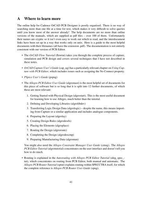
A Where to learn more<br />
The online help for <strong>Cadence</strong> <strong>OrCAD</strong> <strong>PCB</strong> <strong><strong>Design</strong>er</strong> is poorly organised. There is no way of<br />
searching more than one file at a time for text, which makes it very difficult to solve queries<br />
until you know most of the answer already! The help documents are no more than online<br />
versions of the manuals, which are supplied as pdf files – over 100 of them. Unfortunately<br />
their names are cryptic so it isn’t even easy to work out which to read, and the interdocument<br />
links have been set up in a way that works only on unix. Here is a guide to the most helpful<br />
documents with their filenames (all have the extension .pdf). The documentation is not entirely<br />
consistent with our version of <strong>PCB</strong> Editor.<br />
• The <strong>OrCAD</strong> Flow Tutorial (flowtut) takes you through the complete process of capture,<br />
simulation and <strong>PCB</strong> design and covers several techniques that I have not described in<br />
these notes.<br />
• <strong>OrCAD</strong> Capture User’s Guide (cap_ug) has a particularly relevant chapter on Using Capture<br />
with <strong>PCB</strong> Editor, which includes issues such as assigning the No Connect property.<br />
• PSpice User’s Guide (pspug)<br />
• The Allegro <strong>PCB</strong> Editor User Guide (algromast) is the most helpful set of documents for<br />
this piece of software but is so long that it is split into 12 further documents, of which<br />
these are most relevant:<br />
1. Getting Started with Physical <strong>Design</strong> (algrostart). This is the most useful document<br />
for learning how to use Allegro, much better than the tutorial.<br />
2. Defining and Developing Libraries (algrolibdev)<br />
3. Transferring Logic <strong>Design</strong> Data (algrologic) – despite the name, this means importing<br />
from Capture or a similar application and includes analogue components.<br />
4. Preparing the Layout (algrolay)<br />
5. Creating <strong>Design</strong> Rules (algrodesrls)<br />
6. Placing the Elements (algroplace)<br />
7. Routing the <strong>Design</strong> (algroroute)<br />
8. Completing the <strong>Design</strong> (algrodescmp)<br />
9. Preparing Manufacturing Data (algroman)<br />
You might also need the Allegro Constraint Manager User Guide (cmug). The Allegro<br />
<strong>PCB</strong> Editor Tutorial (algrotutorial) concentrates on the user interface and doesn’t tell you<br />
how to do much.<br />
• Routing is explained in the Autorouting with Allegro <strong>PCB</strong> Editor Tutorial (aleg_spec_tut),<br />
which concentrates on routing from <strong>PCB</strong> Editor, both manual and automatic. The<br />
Allegro <strong>PCB</strong> Router Tutorial (sptut) explains routing within SPECCTRA itself, for which<br />
the complete reference is Allegro <strong>PCB</strong> Router User Guide (spug).<br />
41
Command Mapping<br />
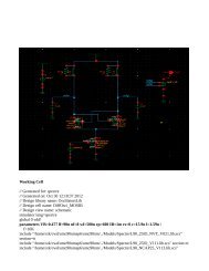
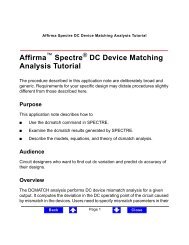
Figure A-1 Allegro <strong>PCB</strong> Editor Toolbar Icons<br />
Show<br />
Element<br />
Cns Show<br />
Shape Add<br />
Shape Add Rect<br />
Show<br />
Measure<br />
Shape Add Circle<br />
Create Detail<br />
Hilight<br />
Shape Select<br />
Dehilight<br />
Shape Void Element<br />
Highlight<br />
SOV<br />
Shape Void Polygon<br />
Dimension Linear<br />
Waive DRC<br />
Shape Edit Boundary<br />
Shape Void Rectangle<br />
Shape Void Circle<br />
Dimension Angular<br />
Grid Toggle<br />
Color192<br />
Island Delete<br />
Leader Diametral<br />
Shadow<br />
Toggle<br />
Signal Library<br />
Leader Radial<br />
Xsection<br />
Signal Model<br />
Dfa_Spreadsheet<br />
Cmgr<br />
Signal Audit<br />
Generaledit<br />
Signal Probe<br />
Ifp<br />
Place<br />
Manual<br />
Place<br />
Manual-H<br />
Figure 22. Toolbars in Allegro, taken from the Allegro <strong>PCB</strong> and Package Physical Layout<br />
Command Reference. Not all of the buttons are available in <strong>OrCAD</strong> <strong>PCB</strong> Editor and many<br />
provide The command functionsmapping that I have innot Table described. A-1 lists the menu choices that can be found in the different<br />
modes (Layout and Symbol) of Allegro <strong>PCB</strong> Editor. If you are running a different product in<br />
the Allegro family (for example, <strong>PCB</strong> <strong>Design</strong> 220), some commands listed here might not be<br />
available. • If you know precisely which <strong>PCB</strong> Editor command is involved, there is a file for commands<br />
starting with each letter. They are called A Commands (acoms) to Z Commands<br />
Table (zcoms). A-1 Allegro The names <strong>PCB</strong> of Editor the commands Command areMapping not always obvious, in which case the Allegro<strong>PCB</strong><br />
and Package Physical Layout Command Reference (cmdrefmast) is the place to<br />
Menu start. Choice The new board wizard is under L (layout wizard), Console for instance, Window which confuses Command me<br />
repeatedly. Figure 22 for the toolbars is taken from this manual.<br />
June 2007 11 Product Version 16.0<br />
Prmed<br />
Ncdrill Legend<br />
Odb Out<br />
Ncdrill Param<br />
Artwork<br />
Net Schedule<br />
Slide<br />
Add Connect<br />
Ncdrill Customization<br />
Testprep Manual<br />
Testprep Automatic<br />
Silkscreen Param<br />
Spread Between Voids<br />
Custom<br />
Smooth<br />
Delay Tune<br />
Thieving<br />
Reports<br />
Vertex<br />
Help<br />
Drc Update<br />
Rplan Plan Rplan Toggle<br />
Bundle Edit<br />
Bundle Create Bundle Properties Rplan Commit<br />
Linefont<br />
Leader Only<br />
Leader Chamfer Autobundle<br />
Bundle Split<br />
Rplan Status<br />
Create Fanout Dimension Datum Leader Balloon Etchedit Bundle Delete<br />
Flow Default<br />
Bundle Toggle<br />
42
B Power-user tips for the future and random jottings<br />
This is a disorganised collection of techniques that I have found useful but seemed too complicated<br />
for the body of this handout (which is already far too long).<br />
B.1 Modes of operation<br />
I didn’t dwell on this in the instructions because we would all rather try out the software than<br />
read a lengthy ‘theory of operation’ but here is a little more. The main point is that the tools<br />
in <strong>PCB</strong> Editor can be used in two different ways (see page 23 of Getting Started with Physical<br />
<strong>Design</strong> for further details).<br />
• Menu-driven editing mode or verb–noun use model. In this mode you first choose a<br />
command, either from the menu bar or by clicking a button, then the design element on<br />
which the tool should operate.<br />
• Pre-selection mode or noun–verb use model. In this mode you first choose the object<br />
followed by the command, which is usually selected from the contextual menu by rightclicking.<br />
The verb–noun approach is a little more cumbersome but it is much easier to see what is happening,<br />
particularly if you keep the control panels open. For example, if you choose Add<br />
Connect, the Find panel automatically selects Pins, Vias and so on – the items to which a connection<br />
can be added. The Options displays the etch layers available and options for the tracks,<br />
such as width and angle of bends. If the Move command is selected instead, different options<br />
are offered and other classes are activated in Find.<br />
The noun–verb model is often more convenient when you know what you are doing and<br />
want to perform a set of operations on an object. However, there is a huge number of possible<br />
operations and they don’t all fit into a contextual menu. <strong>PCB</strong> Editor therefore has two Application<br />
Modes, which can be selected from the menu bar with Setup > Application Mode or with a<br />
button. These are the modes.<br />
• General Edit (GEN). This is the most useful mode and is intended for arranging components<br />
and adding connections.<br />
• Etch Edit (EE). This is mainly for editing tracks that have already been routed.<br />
The current mode is shown near the right-hand end of the status bar below the windows.<br />
The particular set of commands in the contextual menu depends on exactly what is selected.<br />
You may therefore need to adjust the Find control panel before you are able to select the desired<br />
element – a pin for Add Connect, for instance.<br />
Fancier versions of Allegro have a third mode for Flow Planning and there is an empty<br />
space on the button bar for it but it is not available to us.<br />
Use Setup > Application Mode > None to exit from the current application mode and return<br />
to a menu-driven editing mode (there is no button). No contextual menu is available and the<br />
Find control panel is deactivated until a tool or application mode is chosen again. If <strong>PCB</strong> Editor<br />
appears ‘dead’ there is probably no application mode selected.<br />
If that isn’t enough, there are further shortcuts described on pages 34–35 of Getting Started<br />
with Physical <strong>Design</strong>. These are the actions that take place by default when you click and drag<br />
43
on an object, often while holding a modifier key down, and are the quickest ways of performing<br />
the most common actions. For example, in general editing mode:<br />
• dragging a symbol, text or via moves it<br />
• control-dragging a symbol, text or via duplicates it<br />
• shift-dragging a symbol rotates (spins) it<br />
• dragging a cline segement slides it<br />
Similarly, in etch editing mode:<br />
• dragging a cline segement slides it<br />
• double-clicking a pin or via adds a connection (and this can be shortened further to a<br />
single click with the contextual menu Customize > Enable Single Click Execution)<br />
That should be enough for now!<br />
B.2 <strong>Design</strong> rules, particularly width of tracks.<br />
The suggested design rules do not permit a track to run between the pads of of an integrated<br />
circuit, 0.1 ′′ apart. This keeps the board easy to solder but makes it more difficult to route. If<br />
you wish to allow tracks between the pads, reduce the Minimum line to pad spacing to 12 mils<br />
in the New Board Wizard. For an existing design use Setup > Constraints > Spacing. . . to<br />
bring up the Constraint Manager, select Spacing Constraint Set > All Layers and change the<br />
appropriate entries from 20 to 12. You will need to solder the board carefully!<br />
It can be helpful to change the width of a track along its length, particularly if the tracks<br />
are narrow, because our etching process tends to attack long, isolated tracks; keep them at least<br />
20 mil wide. You can change the width during manual routing with the Options control panel<br />
or contextual menu.<br />
B.3 Editing padstacks to include guide holes for drilling<br />
Here’s how to fix the padstacks so that they can be plotted with a guide hole for drilling. The<br />
trick is to use the solderpaste layer for the guide hole. (I’m grateful to redwire and other<br />
members of the <strong>Cadence</strong> forum for help with this. The procedure should become obsolete with<br />
version 16.2.) See Library Padstacks in Defining and Developing Libraries, Layout Padstacks,<br />
Vias, and Etch Shapes in Preparing the Layout, and Padstack <strong><strong>Design</strong>er</strong> in P Commands for full<br />
details.<br />
1. Right-click on a pin and choose Modify <strong>Design</strong> Padstack > All Instances. Alternatively,<br />
choose Tools > Padstack > Modify <strong>Design</strong> Padstack. . . from the menu bar and select a<br />
padstack either by clicking or from the Options control panel. The Padstack <strong><strong>Design</strong>er</strong><br />
starts.<br />
2. You will probably see the Parameters tab first. There’s probably no need to touch this<br />
unless you want to adjust the diameter of the hole.<br />
44
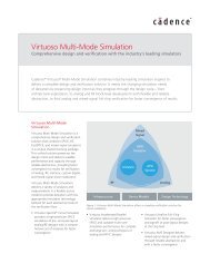
Figure 23. Padstack editor settings with a pastemask to act as a dummy hole.<br />
3. The Layers tab needs the work. See figure 23. I’m not sure what the Thermal Relief and<br />
Anti Pad should be, but these settings avoid complaints.<br />
• The TOP and BOTTOM layers should have the dimensions of the copper under<br />
Regular Pad. It is best to set the Thermal Relief and Anti Pad to null.<br />
• The DEFAULT INTERNAL layer has the same dimensions in all three categories.<br />
• SOLDERMASK_TOP and SOLDERMASK_BOTTOM have the same size Regular<br />
Pad as the others.<br />
• I have edited the PASTEMASK_TOP and PASTEMASK_BOTTOM to have a circular<br />
Regular Pad with diameter 20 mil. This will become the guide hole in the<br />
final plot.<br />
There are further commands to replace padstacks and to purge unused padstacks from a design.<br />
B.4 Alternative design flow<br />
If you don’t like the idea of the new board wizard, you can follow a more conventional but<br />
clumsier flow to start the board. It gives a little more control.<br />
1. Send the netlist from Capture to <strong>PCB</strong> Editor without first setting up a bare board. Leave<br />
the Input Board File empty in the Create Netlist dialogue box, figure 7 on page 16.<br />
45
2. In <strong>PCB</strong> Editor, use Setup > Outlines > Board Outline to define the outline of the board<br />
and the route and package keepins, which are made identical. The same dialogue box can<br />
be used to change these outlines later. You might wish to draw a different route keepin<br />
with Setup > Areas > Route Keepin.<br />
I have not tried placing the components first and subsequently drawing the board outline<br />
and keepins around them. You would obviously have to keep DRC off.<br />
3. Import a technology file with File > Import > Techfile when we set one up! Until then<br />
you will have to work through the steps below.<br />
4. Use Setup > Cross-section to define the number, names and types of layers. The default<br />
is two layers, which is fine.<br />
5. Set up the grids with Setup > Grids. I suggest 100 mil for the non-etch layers and 25 mil<br />
for the etch.<br />
6. Define the widths of tracks with Setup > Constraints > Physical and the separations with<br />
Setup > Constraints > Spacing. While you are doing this, edit the vias in the Physical<br />
pane as described on page 38.<br />
7. You might wish to tweak some of the parameters in Setup > <strong>Design</strong> Parameters > Display,<br />
such as the display of drill holes and the ratsnest. Their visibility is treated differently<br />
from other elements of the design. (At present you can display the drill holes on<br />
the screen but not plot them.)<br />
B.5 Miscellaneous <strong>PCB</strong> Editor tips<br />
There seems to be no Unroute Board command within <strong>PCB</strong> Editor, which would be helpful if<br />
you made a complete mess of routing. One method is to reload the design, assuming that you<br />
saved it first. Alternatively, try this.<br />
1. Open the Find control panel and select Nets only.<br />
2. Drag across the design to select all the nets.<br />
3. All the nets are now highlighted in the main window. Right-click and choose Ripup etch.<br />
I haven’t described how to produce Gerber files and the like, which require the Manufacture<br />
menu of <strong>PCB</strong> Editor. This will depend on the demands of the company involved. See Preparing<br />
Manufacturing Data.<br />
It should be possible to set up colour files that make it simpler to produce photomasks. I<br />
haven’t yet got this to work reliably. The colorview commands are described in C Commands.<br />
I haven’t explained how to add mechanical features such as mounting holes, which ought to<br />
be remedied. These can be placed by selecting Place > Manually. . . and choosing Mechanical<br />
symbols from the drop-down list. Click the Advanced Settings tab and choose Library because<br />
these symbols will not be in the database imported from Capture.<br />
I haven’t explained how to do pours (nor have I tried it myself).<br />
Our local allegro library doesn’t yet include mechanical symbols. There is another problem<br />
with the electrical symbols too: the values have vanished. The padstacks have proliferated<br />
46
into a mess too. The main references for this job are Defining and Developing Libraries and<br />
Preparing the Layout. Issues with importing from Capture are covered in Preparing your<br />
design for use with <strong>PCB</strong> Editor in the Capture UserÕs Guide. The conversion of libraries from<br />
Layout is described under the orcad in command in O Commands.<br />
It would be convenient if the schematic circuit could be drawn once with both ‘virtual<br />
components’ such as sources for simulation and sockets for the real <strong>PCB</strong>. Unfortunately this<br />
cannot be done without editing the components in the pspice library because some have pins<br />
numbered 0, which allegro rejects. Many of the libraries are full of bugs. Some components<br />
have pins numbered with letters (such as the electrolytic capacitor) and some aren’t numbered<br />
at all.<br />
I find it helpful to adjust the grids produced by the new board wizard, which are the same<br />
for everything. Choose Setup > Grids. . . from the menu bar and change the Spacing figures<br />
for Non-Etch (essentially the components) to 100. Leave the remaining spacings at 25.<br />
Lines in the ratsnest are ‘jogged’ by default. I prefer to join the components with straight<br />
lines instead. Choose Setup > <strong>Design</strong> Parameters. . . from the menu to bring up the <strong>Design</strong><br />
Parameter Editor. Select the Display tab and adjust the Ratsnest geometry to Straight.<br />
There are two types of ‘design’ file that both use the extension .dsn, but whose contents are<br />
entirely different.<br />
• Capture has a design file to hold its database (Windows calls it a Data Source Name)<br />
• <strong>PCB</strong> Editor uses a design file to export the board to the autorouter.<br />
Don’t let them get mixed up! This is one of the reasons for setting up a separate allegro<br />
subdirectory.<br />
There is a high chance of error if you copy names of footprints from a document and type<br />
them manually: It is better practice to select them from a library. This is a bit clumsy in <strong>PCB</strong><br />
Editor. (Perhaps there is a better way that I have yet to discover because this worked better in<br />
Layout. A listing of the directory might be easier.)<br />
1. Choose Place > Manually. . . from the menu bar.<br />
2. Click the Advanced Settings tab and choose to Display definitions from Library.<br />
3. Return to the Placement List and select Package symbols from the drop-down list. You<br />
will now see a list of all packages in the libraries.<br />
4. Scroll down to find the outline that you want, RC400 for example. Click in the check<br />
box next to the component and a graphic appears in the Quickview window. This helps<br />
you to confirm that it is the correct outline, although there is no scale.<br />
5. Select the Text radio button and the name of the component appears. You can copy this<br />
and paste it into the Properties Editor in Capture.<br />
6. Dismiss the Placement box with Cancel when you have finished and quit from <strong>PCB</strong><br />
Editor without saving any changes.<br />
47
B.6 SPECCTRA tips<br />
Tracks can be edited in SPECCTRA instead of <strong>PCB</strong> Editor. This is handy for moving badlyplaced<br />
vias (I found it easier than <strong>PCB</strong> Editor). Right-click in the window, which brings up<br />
the INTERACTIVE ROUTING MENU. Move mode is probably the most useful. You can then<br />
select tracks or vias and move them. This is best done before the finishing touches of spreading<br />
and mitring. In fact you can do most of the placement and routing in SPECCTRA but I didn’t<br />
want to describe yet another interface.<br />
If you export a fully or partly routed board from <strong>PCB</strong> Editor to SPECCTRA, the imported<br />
tracks are protected against changes in SPECCTRA. Choose Edit > [Un]protect > Wires by<br />
Net. . . (or Wires by Layer List. . . ) to remove the protection. You can then unroute these tracks<br />
and reroute the board.<br />
48