Project Manual Industrial Hydraulics - Bosch Rexroth
Project Manual Industrial Hydraulics - Bosch Rexroth
Project Manual Industrial Hydraulics - Bosch Rexroth

Create successful ePaper yourself
Turn your PDF publications into a flip-book with our unique Google optimized e-Paper software.
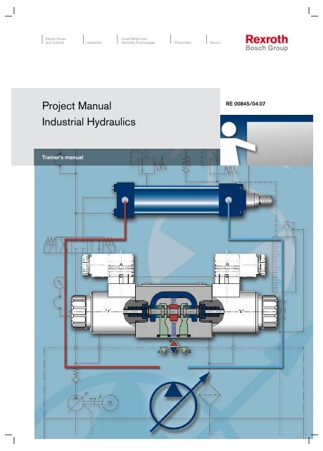
Electric Drives<br />
and Controls <strong>Hydraulics</strong><br />
<strong>Project</strong> <strong>Manual</strong><br />
<strong>Industrial</strong> <strong>Hydraulics</strong><br />
Trainer‘s manual<br />
Linear Motion and<br />
Assembly Technologies Pneumatics Service<br />
RE 00845/04.07
Electric Drives<br />
and Controls <strong>Hydraulics</strong><br />
A<br />
B<br />
C<br />
D<br />
Introduction<br />
A<br />
Linear Motion and<br />
Assembly Technologies Pneumatics Service<br />
Introduction<br />
Imparting knowledge through project work • <strong>Project</strong> designation with short description of<br />
the industrial application • Comparison of project exercises <strong>Bosch</strong> <strong>Rexroth</strong> AG/BIBB •<br />
Component matrix • Overview of components • Safety aspects<br />
Basic principles of hydraulics<br />
System technologies/energy conversion • Simple hydraulic circuit • Symbols according<br />
to DIN ISO 1219-1 • Circuit systems in the field of hydraulics • Demands placed on drive<br />
elements • Physical basic principles • Hydraulic fluids • Filtration<br />
<strong>Project</strong> tasks<br />
Fundamental safety notes • 01 Hydraulic power unit • 02 Hydraulic pump/variable displacement<br />
pump characteristic curve • 03 Single-rod cylinder/pressure intensification •<br />
04 Single-rod cylinder/flow • 05 Hydraulic motor • 06 4/3 directional valve • 07 Check<br />
valve • 08 Check valve, pilot operated • 09 Throttle valve, adjustable • 10 Throttle check<br />
valve • 11 Flow control valve • 12 Pressure relief valve, direct operated • 13 Pressure relief<br />
valve controls • 14 Pressure reducing valve • 15 Pressure switch • 16 Pressure switch/<br />
hysteresis • 17 Hydraulic accumulator • 18 Regenerative circuit • 19 Rapid speed/creep<br />
speed control • 20 Valve circulation control • 21 Commissioning, inspection, maintenance,<br />
troubleshooting, repair<br />
Annex<br />
RE 07008 General product information about hydraulic products from<br />
<strong>Bosch</strong> <strong>Rexroth</strong> AG<br />
Introduction<br />
A
<strong>Project</strong> 0 :<br />
Single-rod cylinder / pressure intensification <strong>Bosch</strong> <strong>Rexroth</strong> AG I RE 00845/04.07<br />
<strong>Project</strong> 03: Single-rod cylinder/pressure intensification<br />
<strong>Project</strong>/trainer information<br />
If in a hydraulic system the hydraulic force, which is converted into mechanical energy, is to be<br />
transmitted to an actuator in the form of a linear (straight) movement, a hydraulic cylinder is<br />
used. We distinguish hydraulic cylinders by their design principles:<br />
Plunger, single-rod and double-rod cylinders.<br />
The hydraulic cylinder as output element forms the link between the hydraulic circuit and the<br />
working element/tool in a technological system. Lifting, lowering, locking and transporting loads<br />
are typical applications of hydraulic cylinders.<br />
Neglecting friction, the possible maximum cylinder force F in kN depends on the possible<br />
maximum system pressure p and the effective piston area A of the hydraulic cylinder, i.e.<br />
F = p • A in dN p in bar; A in cm 2<br />
The piston velocity v in m/s of the hydraulic cylinder is determined by the pump flow supplied.<br />
Flow control valves are used to change, i.e. reduce, the piston velocity. When throttling, for<br />
example, the piston extension velocity, important physical laws must be taken into account.<br />
In the following <strong>Project</strong> 03 knowledge can be imparted with regard to the use of single-rod<br />
cylinders as machine elements.<br />
In the project order, the trainee is to work out the physical basic principles of pressure intensification<br />
with single-rod cylinders. On the basis of this project task, he/she is to understand<br />
the following:<br />
• The hydraulic cylinder performs a straight movement and transmits the supplied piston pressure<br />
in the form of force.<br />
• Double-acting hydraulic cylinders with different piston areas are pressure intensifiers.<br />
• Due to adhesive friction in the hydraulic cylinder the pressure actually transmitted via the<br />
piston area or through the differences in areas is reduced.<br />
• Forces and velocities can be kept constant over the entire stroke.<br />
Biased on the control set up on the training system the trainee is to learn that the use of a meterout<br />
throttle on the piston rod side involves a risk of pressure intensification. When the hydraulic<br />
pump is switched on, the piston of the single-rod cylinder extends. The extension velocity can<br />
be varied by means of a throttle valve. Retracting of the single-rod cylinder is accomplished<br />
with the help of a 4/2 directional valve.<br />
Notes on detailed technical information about hydraulic cylinders:<br />
• The Hydraulic Trainer Volume 1/<strong>Bosch</strong> <strong>Rexroth</strong> AG<br />
Basic principles and components, Chapter 7<br />
• Technical data sheet RE 17039<br />
Hydraulic cylinders of tie rod design<br />
03
<strong>Project</strong> 0 :<br />
Single-rod cylinder / pressure intensification <strong>Bosch</strong> <strong>Rexroth</strong> AG I RE 00845/04.07<br />
<strong>Project</strong> definition<br />
<strong>Project</strong> tasks<br />
A workpiece is to be shifted by a horizontally installed single-rod cylinder to the working range<br />
of a simple fixture when the hydraulic pump is switched on. To this end, the extension velocity<br />
of the cylinder must be adjustable. Retracting is to be achieved by means of a 4/2 directional<br />
valve.<br />
The customer installed a throttle valve on the piston rod side and, while adjusting the extension<br />
velocity, recognizes that the pressure upstream of the throttle becomes higher than the set<br />
system pressure. Apart from the technical documentation he wishes to get an explanation of<br />
the pressure intensification of the single-rod cylinder.<br />
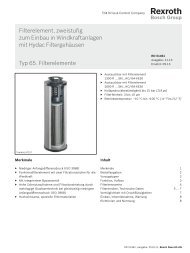
Fig. 03.1 Practical example: Hydraulic cylinder of tie rod design<br />
• Independent understanding and execution of the task set through application of hydraulic<br />
control technology<br />
• Planning and organizing the customer requirement (core qualification)<br />
• Analyzing the technical data sheet of a hydraulic cylinder (specialist qualification)<br />
• Handling of hydraulic components in line with functional needs<br />
03
<strong>Project</strong> 0 :<br />
Single-rod cylinder / pressure intensification <strong>Bosch</strong> <strong>Rexroth</strong> AG I RE 00845/04.07<br />
<strong>Project</strong> steps<br />
Notes<br />
• Informing: Accepting and understanding the order, among others, through discussions<br />
with the customer.<br />
• Planning: Planning and organizing the execution of the customer order; among others,<br />
through the selection of hydraulic components from the data sheet<br />
collection (RE 17039 Hydraulic cylinders, tie rod design).<br />
• Deciding: Preparation of a schematic diagram sketch and selection of components.<br />
• Executing: Set-up of the hydraulic control on the training system. Working out and<br />
documenting the system parameters required by the customer and explanations<br />
with regard to pressure intensification on the basis of a calculation<br />
example.<br />
• Checking: Are all customer requirements met?<br />
• Evaluating: Are there further possibilities of meeting the customer requirement or simpler<br />
ways of project execution? Have unforeseeable problems occurred?<br />
03
<strong>Project</strong> 0 :<br />
Single-rod cylinder / pressure intensification 4<br />
<strong>Bosch</strong> <strong>Rexroth</strong> AG I RE 00845/04.07<br />
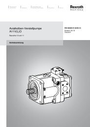
Hydraulic circuit diagram<br />
Item 0.2<br />
Item 0.1<br />
Item 1.1<br />
Item 1.0<br />
Fig. 03.2 Hydraulic circuit diagram: Feeding cylinder<br />
Item 1.3<br />
Item 0.3<br />
Item 1.2<br />
Power unit limit<br />
Measuring<br />
glass<br />
03
<strong>Project</strong> 0 :<br />
Single-rod cylinder / pressure intensification 5<br />
<strong>Bosch</strong> <strong>Rexroth</strong> AG I RE 00845/04.07<br />
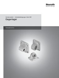
Electrical circuit diagram<br />
Fig. 03.3 Wiring diagram re hydraulic circuit diagram Fig. 03.2<br />
Control 4/ directional valve<br />
Retraction<br />
-Single-rod cylinder-<br />
Note:<br />
The single-rod cylinder<br />
extends automatically<br />
when the hydraulic pump is<br />
switched on.<br />
03
<strong>Project</strong> 0 :<br />
Single-rod cylinder / pressure intensification 6<br />
<strong>Bosch</strong> <strong>Rexroth</strong> AG I RE 00845/04.07<br />
Component selection with parts list<br />
Item Qty Component designation Type designation Symbol<br />
1.0 1<br />
1.1 1<br />
1.2 1<br />
Double-acting cylinder<br />
with single-sided piston rod<br />
4/2 directional valve with solenoid<br />
actuation, spring return<br />
Direct operated pressure relief<br />
valve, the cracking pressure can be<br />
adjusted by means of a spring<br />
ZY 1.3<br />
DW 3 E<br />
DD 1.1<br />
1.3 1 Throttle valve, adjustable DF 1.2<br />
0.1 - 0.3 3<br />
1 Distributor plate with four ports DZ 4.1<br />
3<br />
Pressure gauge with hose<br />
and quick release coupling<br />
without check valve<br />
Hose with quick release coupling<br />
with check valve<br />
DZ 1.4<br />
DZ 25.1<br />
Hose VSK 1<br />
Table 03.1 Parts list for hydraulic circuit diagram Fig. 03.2<br />
03
<strong>Project</strong> 0 :<br />
Single-rod cylinder / pressure intensification 7<br />
<strong>Bosch</strong> <strong>Rexroth</strong> AG I RE 00845/04.07<br />
Component arrangement<br />
Measuring glass<br />
Connection block<br />
Fig. 03.4 Recommended component arrangement with component designations for parts list Table 03.1 and hydraulic circuit diagram Fig. 03.2<br />
Notes<br />
Note:<br />
D Note:<br />
In the case of connection<br />
elements marked with “D”, the<br />
components can be connected<br />
directly with each other.<br />
The designations of components in the parts list and the component arrangement are <strong>Rexroth</strong>specific<br />
designations. Also the grid arrangement is <strong>Rexroth</strong>-specific and adapted for use on<br />
the training system.<br />
03
<strong>Project</strong> 0 :<br />
Single-rod cylinder / pressure intensification 8<br />
<strong>Bosch</strong> <strong>Rexroth</strong> AG I RE 00845/04.07<br />
Safety notes<br />
Warning<br />
Caution<br />
Execution of the order<br />
To ensure the operability of plant and machinery, and consequently to allow<br />
the recognition of potential risks, safety regulations must be observed before<br />
and during the execution of the order. Relevant sources of regulations are<br />
given in the introduction of the present manual.<br />
If work on electrohydraulic components is carried out improperly, risks of<br />
injury and a safety risk can arise during operation of the system, including<br />
danger to life.<br />
Before starting work on the training stand, check that the electrical ON/<br />
OFF switch on the hydraulic power unit is pressed in, i.e. that the system is<br />
switched off. Use the system pressure gauges to check that the system is<br />
depressurized.<br />
Hydraulic systems can store pressure energy when at rest. It can cause injury<br />
when the system is opened.<br />
Set up the control as described below:<br />
1. Mount the components required according to Table 03.1 in a clearly arranged form on the<br />
training system according to the prepared circuit diagram.<br />
Connect the hydraulic control according to hydraulic circuit diagram Fig. 03.2 by means of<br />
hoses.<br />
For connections, to which pressure gauges with minimess line DZ .4 are to be connected,<br />
use hydraulic hoses DZ 5. Hand-tighten the pressure gauge measuring lines at the relevant<br />
minimess connection of the hydraulic hose.<br />
The correct and proper fit of the component connections with hoses can be checked<br />
by slightly turning the hoses.<br />
Make sure that pipes or hoses are connected to all connections - in this case<br />
also to minimess lines, or that the connections are plugged by means of plug<br />
screws or protective caps. Leakage oil may drip through open connections<br />
Warning<br />
and cause a slipping risk.<br />
Before commissioning the hydraulic control, i.e. before switching the hydraulic<br />
pump on, check, whether all pressure control valves are set to minimum<br />
Caution pressure (spring unloaded) and all throttle valves are open.<br />
Wire the electrical control according to wiring diagram Fig. 03.3.<br />
2. Switch the hydraulic pump on and inspect the set up control for leakage. No pressure gauge<br />
may indicate a pressure.<br />
3. Check the pressure set on the variable displacement pump of the drive power unit (if<br />
required, correct to 50 bar).<br />
4. Set the system pressure on pressure relief valve Item . to 50 bar plus one turn; operate<br />
push-button S to prevent the piston of hydraulic cylinder Item .0 from extending.<br />
5. Through operation of push-button S the control voltage of solenoid Y of the 4/2 directional<br />
valves Item . drops, and the piston of the hydraulic cylinder extends due to the pump flow<br />
supplied directly to the piston side.<br />
03
<strong>Project</strong> 0 :<br />
Single-rod cylinder / pressure intensification <strong>Bosch</strong> <strong>Rexroth</strong> AG I RE 00845/04.07<br />
Measured values<br />
6. Switch the hydraulic pump off and wait until the system is depressurized. Close throttle<br />
valve Item . . To this end, turn in the adjustment element counter-clockwise to the limit<br />
stop.<br />
7. Switch the hydraulic pump on. The piston of the hydraulic cylinder cannot extend, because<br />
the counterforce on the piston rod side is greater than the force on the piston side, since<br />
the throttle valve is closed. Pressure gauge M indicates the value of pressure intensification.<br />
Note the measured values and enter them in Table 03.2.<br />
Caution<br />
Hydraulic<br />
cylinder<br />
Extending/<br />
Y1 not operated<br />
After having completed practical work on the training system switch the<br />
hydraulic pump off! Turn pressure relief valve Item . back to minimum<br />
pressure. No pressure gauge may indicate a pressure!<br />
Measuring point M<br />
System pressure p in bar<br />
Table 03.2 Pressure intensification values measured<br />
M piston side<br />
p in bar<br />
The values were measured at an oil temperature of approx. 20 °C.<br />
The values measured by the trainees can deviate by 10 %.<br />
M piston rod side<br />
p in bar<br />
48 48 82<br />
Additional task in conjunction with the customer requirement:<br />
Calculation of the pressure intensification on the basis of given hydraulic cylinder values.<br />
Hydraulic cylinder of tie rod design: Type CD T ... 5/ 8... 00<br />
Bore: 25 mm<br />
Piston rod diameter: 18 mm<br />
A<br />
A<br />
A<br />
piston<br />
rod<br />
annulus<br />
4,91 cm<br />
2,54 cm<br />
= 4,91 cm<br />
= 2,54 cm<br />
2<br />
2<br />
= 2,37 cm 2<br />
2<br />
2<br />
= 2,07 : 1<br />
If the meter-out throttle is completely closed,<br />
then:<br />
F = F<br />
p � A = p � A<br />
p<br />
K R<br />
K K R R<br />
R<br />
= 2,07<br />
1,00<br />
� 50 bar = 103,5 bar<br />
03
<strong>Project</strong> 0 :<br />
Single-rod cylinder / pressure intensification 0<br />
<strong>Bosch</strong> <strong>Rexroth</strong> AG I RE 00845/04.07<br />
Evaluating the work results with regard to the customer requirement<br />
• Hydraulic cylinders perform linear movements and transmit the piston pressure in the form<br />
of force.<br />
• Double-acting hydraulic cylinders with different areas are called single-rod cylinders.<br />
• Single-rod cylinders are pressure intensifiers.<br />
• Velocities can be kept constant over the entire stroke.<br />
03