October 2000 Newsletter - Naval Postgraduate School
October 2000 Newsletter - Naval Postgraduate School
October 2000 Newsletter - Naval Postgraduate School

You also want an ePaper? Increase the reach of your titles
YUMPU automatically turns print PDFs into web optimized ePapers that Google loves.
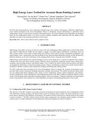
FEATURED PROJECT<br />
JP-10/AEROSOL FOR PULSE DETONATION APPLICATIONS, continued from page 6<br />
successfully detonated a JP-10/air aerosol in a PDE combustor.<br />
Previous research at the laboratory resulted in the first<br />
two-phase detonation of a JP10/oxygen mixture and recent<br />
efforts resulted in the first documented two-phase detonation<br />
of JP-10 and air. The results demonstrate the practicality of<br />
liquid-fuel detonations for PDE applications.<br />
Due to the nature of the combustion process, the mode of<br />
operation for a typical PDE is cyclical. The fuel/<br />
air mixture is loaded into a combustor, rapidly<br />
detonated, and then the products are exhausted.<br />
The resulting pressure behind the detonation wave<br />
presses on the head-end, or thrust wall, of the<br />
combustor to generate thrust. After the combustion<br />
event is complete, the exhaust is expelled<br />
from the combustor and a new fuel/air mixture is<br />
loaded and the procedure repeats. This repeated<br />
fill/detonate/exhaust process typically must occur<br />
at frequencies of 40 Hz or greater to generate a<br />
reasonable thrust level for most systems.<br />
Gaseous systems possess an inherent simplicity<br />
since all of the fuel is already in a vapor state and<br />
is therefore more likely to react rapidly with the<br />
oxidizer, which is required in a detonation wave.<br />
Generally, the energy release must occur within<br />
1cm of the detonation leading shock. If the heat<br />
release occurs too late, the combustion zone<br />
decouples from the shock and the detonation will<br />
likely fail. In a two-phase condition, such as a JP-<br />
10/air aerosol, the fuel must be significantly<br />
vaporized before a substantial reaction can occur.<br />
Calculations indicated that a spray possessing<br />
droplets below 6 microns in diameter would be<br />
required to support a two-phase detonation wave.<br />
The experimental facility used for this work,<br />
shown in Figures 1 and 2, was operated at air flow<br />
rates of up to 1.3 kg/s (3 lbm/s) and provided the<br />
engine with air inlet temperatures of up to 500 K.<br />
The air was heated by a hydrogen vitiator with<br />
make-up oxygen and a maximum outlet temperature<br />
of 725 K. The vitiator outlet was connected<br />
to the engine inlet through a 6.35 cm (2.5 inch)<br />
diameter flex hose. The engine geometry is shown<br />
in Figure 3 with exploded views of selected areas.<br />
The engine inlet choke isolated the vitiator from<br />
pressure oscillations in the main combustor and<br />
allowed for redundant metering of the vitiated air flow. Fuel<br />
was injected just after the inlet choke and was allowed to mix<br />
completely before being discharged into a plenum region and<br />
then injected into the main combustor through a perforated<br />
cone segment in order to provide increased turbulence,<br />
mixing, and partial acoustic isolation.<br />
--continued on page 41<br />
From top to bottom:<br />
Figure 1. Experimental<br />
Layout<br />
Figure 2. Test Cell<br />
View of Experimental<br />
Setup<br />
Figure 3. Pulse<br />
Detonation Engine<br />
Geometry<br />
NPS Research page 7<br />
<strong>October</strong> <strong>2000</strong>