BC2401H - Billy Goat
BC2401H - Billy Goat
BC2401H - Billy Goat
- TAGS
- billygoat.com

You also want an ePaper? Increase the reach of your titles
YUMPU automatically turns print PDFs into web optimized ePapers that Google loves.
1<br />
2<br />
ACCESSORIES<br />
NUT REPLACEMENT KIT<br />
P/N 500208.<br />
To replace stripped or<br />
damaged insert nuts in<br />
engine base.<br />
BLADE BC2401<br />
P/N 500210.<br />
Original Equipment Blade<br />
for replacement.<br />
BELT TRACTION DRIVE<br />
P/N 500119.<br />
Traction Drive Belt<br />
for BC2401<br />
BELT BLADE DRIVE<br />
P/N 500237.<br />
Blade Drive Belt<br />
for BC2401<br />
BLADE HIGH LIFT<br />
BC2401<br />
P/N 500102.<br />
Optional blade for<br />
replacement<br />
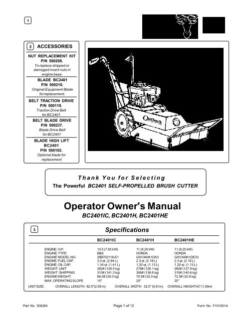
Thank You for Selecting<br />
The Powerful BC2401 SELF-PROPELLED BRUSH CUTTER<br />
Operator Owner's Manual<br />
BC2401IC, <strong>BC2401H</strong>, <strong>BC2401H</strong>E<br />
3 Specifications<br />
BC2401IC <strong>BC2401H</strong> <strong>BC2401H</strong>E<br />
ENGINE: H.P. 10.5 (7.83 kW) 11 (8.20 kW) 11 (8.20 kW)<br />
ENGINE: TYPE B&S HONDA HONDA<br />
ENGINE MODEL NO: 28B702118-E1 GXV340K1DX3 GXV340K1DE33<br />
ENGINE: FUEL CAP. 3.0 qt. (2.84 L) 2.3 qt. (2.18 L) 2.3 qt. (2.18 L)<br />
ENGINE: OIL CAP. 1.34 qt. (1.41 L) 1.20 qt. (1.13 L) 1.20 qt. (1.13 L)<br />
WEIGHT: UNIT 282# (128.5 kg) 278# (126.1 kg) 282# (127.9 kg)<br />
WEIGHT: SHIPPING 310# (141.3 kg) 306# (138.8 kg) 310# (140.6 kg)<br />
ENGINE WEIGHT: 66.0# (30.0 kg) 70.5# (32.0 kg) 72.5# (32.9 kg)<br />
MAX. OPERATING SLOPE 15° 20° 20°<br />
UNIT SIZE: OVERALL LENGTH: 82.5"(2.09 m) OVERALL WIDTH 32.0" (0.81m) OVERALL HEIGHT43" (1.09m)<br />
Part No. 500264 Page 1 of 12<br />
Form No. F101001A
5 IN THE INTEREST OF SAFETY<br />
WARNING: DO NOT<br />
1. DO NOT run engine in an enclosed<br />
area. Exhaust gases contain carbon<br />
monoxide, an odorless and deadly poison.<br />
2. DO NOT place hands or feet near<br />
moving or rotating parts.<br />
3. DO NOT store, spill or use gasoline<br />
near an open flame, or devices such as a<br />
stove, furnace, or water heater which use<br />
a pilot light or devices which can create a<br />
spark.<br />
4. DO NOT refuel indoors where area is<br />
not well ventilated. Outdoor refueling is<br />
recommended.<br />
5. DO NOT fill fuel tank while engine is<br />
running. Allow engine to cool for 2<br />
minutes before refueling. Store fuel in<br />
approved safety containers.<br />
6. DO NOT remove fuel tank cap while<br />
engine is running.<br />
7. DO NOT operate engine when smell of<br />
gasoline is present or other explosive<br />
conditions exist.<br />
8. DO NOT operate engine if gasoline is<br />
spilled. Move machine away from the spill<br />
and avoid creating any ignition until the<br />
gasoline has evaporated.<br />
9. DO NOT transport unit with fuel in tank.<br />
10. DO NOT smoke when filling fuel tank.<br />
11. DO NOT choke carburetor to stop<br />
engine. Whenever possible, gradually<br />
reduce engine speed before stopping.<br />
12. DO NOT run engine at excessive<br />
speeds. This may result in<br />
injury<br />
6<br />
BEFORE STARTING ENGINE, READ AND UNDERSTAND THE “ENTIRE OPERATOR'S MANUAL &<br />
ENGINE MANUAL.”<br />
THIS SYMBOL MEANS WARNING OR CAUTION. DEATH, PERSONAL INJURY AND/OR PROPERTY<br />
DAMAGE MAY OCCUR UNLESS INSTRUCTIONS ARE FOLLOWED CAREFULLY.<br />
WARNING: The Engine Exhaust from this product contains chemicals known<br />
to the State of California to cause cancer, birth defects or other reproductive harm.<br />
TABLE OF CONTENTS<br />
SAFETY INSTRUCTIONS<br />
GENERAL SAFETY<br />
ASSEMBLY<br />
LIT. BAG & CONTROLS<br />
LABELS<br />
OPERATION<br />
MAINTENANCE<br />
PARTS DRAWING & LIST<br />
TROUBLESHOOTING<br />
WARRANTY PROCEDURE<br />
2<br />
3<br />
3<br />
4<br />
4<br />
5, 9<br />
10 - 12<br />
6 - 8<br />
12<br />
12<br />
& /or damage to unit.<br />
13. DO NOT tamper with governor springs,<br />
governor links or other parts which may<br />
change the governed engine speed.<br />
14. DO NOT tamper with the engine speed<br />
selected by the engine manufacturer.<br />
15. DO NOT check for spark with spark plug<br />
or spark plug wire removed. Use an<br />
approved tester.<br />
16. DO NOT crank engine with spark plug<br />
removed. If engine is flooded, place throttle<br />
in “FAST” position and crank until engine<br />
starts.<br />
17. DO NOT strike flywheel with a hard<br />
object or metal tool as this may cause<br />
flywheel to shatter in operation. Use proper<br />
tools to service engine.<br />
18. DO NOT operate engine without a<br />
muffler. Inspect periodically and replace, if<br />
necessary. If engine is equipped with<br />
muffler deflector, inspect periodically and<br />
replace, if necessary, with correct deflector.<br />
19. DO NOT operate engine with an<br />
accumulation of grass, leaves, dirt or other<br />
combustible material in the muffler area.<br />
20. DO NOT use this engine on any forest<br />
covered, brush covered, or grass covered<br />
unimproved land unless a spark arrester is<br />
installed on the muffler. The arrester must<br />
be maintained in effective working order by<br />
the operator. In the State of California the<br />
above is required by law (Section 4442 of<br />
the California Public Resources Code).<br />
Other states may have similar laws. Federal<br />
laws apply on federal lands.<br />
21. DO NOT touch hot muffler, cylinder, or<br />
fins because contact may cause burns.<br />
22. DO NOT run engine without air cleaner<br />
or air cleaner cover.<br />
23. DO NOT operate during excessive<br />
vibration!<br />
24. DO NOT leave machine unattended<br />
while in operation.<br />
25. DO NOT park machine on a steep grade<br />
or slope.<br />
WARNING: DO<br />
1. ALWAYS DO remove the wire from the<br />
spark plug when servicing the engine or<br />
equipment TO PREVENT ACCIDENTAL<br />
STARTING.<br />
2. DO keep cylinder fins and governor<br />
parts free of grass and other debris<br />
which can affect engine speed.<br />
3. DO pull starter cord slowly until resistance<br />
is felt. Then pull cord rapidly to avoid<br />
kickback and prevent hand or arm injury.<br />
4. DO examine muffler periodically to be<br />
sure it is functioning effectively. A worn or<br />
leaking muffler should be repaired or<br />
replaced as necessary.<br />
5. DO use fresh gasoline. Stale fuel can<br />
gum carburetor and cause leakage.<br />
6. DO check fuel lines and fittings frequently<br />
for cracks or leaks. Replace if necessary<br />
7. Follow engine manufacturer operating<br />
and maintenance instructions.<br />
8. Inspect machine and work area before<br />
starting unit.<br />
7 SOUND<br />
8<br />
VIBRATION<br />
SOUND TESTS<br />
Sound tests conducted were in accordance<br />
VIBRATION LEVEL 1.1g<br />
Vibration levels at the operators handles were<br />
measured in the vertical, lateral, and longitudinal<br />
with 79/113/EEC and were performed on 05/19/ directions using calibrated vibration test equipment.<br />
95 under the conditions listed:<br />
Tests were performed on 05/19/95 under the<br />
GENERAL CONDITION:<br />
Sunny<br />
conditions listed:<br />
GENERAL CONDITION:<br />
Sunny<br />
TEMPERATURE:<br />
62 °F (16.7 °C)<br />
TEMPERATURE:<br />
72 °F (22.2 °C)<br />
WIND SPEED:<br />
5 MPH (8 kmh) WIND SPEED:<br />
5 MPH (8 kmh)<br />
WIND DIRECTION:<br />
South<br />
WIND DIRECTION:<br />
S.W.<br />
OPERATOR HUMIDITY:<br />
67%<br />
HUMIDITY:<br />
67 %<br />
BAROMETRIC PRESSURE:<br />
30.06" Hg (763mm Hg)<br />
BAROMETRIC PRESSURE:<br />
Part No. 500264 Page 2 of 12 30.06" Hg (763mm Hg)<br />
Form No. F101001A
9<br />
10<br />
GENERAL SAFETY<br />
For your safety and the safety of others, these directions should be followed:<br />
Do not operate this machine without first reading<br />
owner's manual and engine manufacturer's manual.<br />
Use of Eye and Breathing protection is recommended<br />
when using this machine.<br />
·DO NOT place hands or feet beneath cutting deck, near<br />
debris outlet or near any moving parts.<br />
·DO NOT start engine or operate unit with bystanders in or<br />
near the work area.<br />
·DO NOT start or operate machine with blade or drive clutch<br />
engaged.<br />
ASSEMBLY<br />
Read all safety and operating instructions<br />
before assembling or starting this unit.<br />
PUT OIL IN ENGINE BEFORE STARTING.<br />
Your <strong>Billy</strong> <strong>Goat</strong> Brush Cutter is shipped from the<br />
factory in one carton, completely assembled except<br />
for the upper handle, and front guard bar.<br />
11<br />
Use of Ear Protection is recommended while<br />
operating this machine.<br />
DISCONNECT SPARK PLUG WIRE<br />
BEFORE ASSEMBLING UNIT.<br />
PACKING CHECKLIST<br />
These items should be included in your carton. If<br />
any of these parts are missing, contact your dealer.<br />
·DO NOT operate during excessive vibration.<br />
·DO NOT perform any maintenance or inspection until engine has<br />
been turned off and has come to a complete stop, and the spark<br />
plug has been removed<br />
·DO NOT operate machine with guards removed.<br />
·DO NOT use this machine for cutting areas containing rock,<br />
glass, string like material, wire, rags, cans, metal, or other nonorganic<br />
material.<br />
·DO NOT operate this machine on slopes greater than specified<br />
on page 1.<br />
·DO NOT operate machine near any hot or burning debris, or any<br />
toxic or explosive material.<br />
·DO NOT allow children to operate this equipment.<br />
1. REMOVE unit from carton and allow upper handle (item 40) to lay on<br />
ground behind unit. Set guard bar(Item 31) to the side for now.<br />
2. REMOVE hardware items 115, 117, 141, 143, & 144 from temporary<br />
storage positions on lower handle (items 51, & 52).<br />
3. ATTACH upper handle to lower as shown below, and securely tighten<br />
all fasteners. For easy alignment of handles during installation, loosen the<br />
four screws that secure the lower handles. Line up and hand tighten all<br />
handle hardware before final tightening. Note: Be sure the engine starter<br />
rope is properly installed in the starter rope guide (item 145) before<br />
tightening the corresponding fasteners.<br />
4. REMOVE hardware items 102, 103, 117, 119, 124, 141, & 152 from<br />
temporary storage positions on deck and skid assy at front of unit<br />
(items 2, 155, & 156)<br />
5. ATTACH guard bar(Item 31) to deck as shown below. Install the center<br />
bolts(Item 153) first, and install the bolts that fasten through the sides of<br />
the deck last. Securely tighten all fasteners. Note: Hardware items 117,<br />
119, & 141 are used to secure both the front skid attachment and the<br />
sides of the guard bar. Be sure both are securely attached.<br />
6. CONNECT spark plug wire to spark plug.<br />
Literature<br />
Assy<br />
Engine<br />
Manual<br />
Per Model<br />
Handle Upper<br />
Assembly<br />
500256<br />
Bar Support WA<br />
500235<br />
Literature Assy<br />
500263<br />
Briggs & Stratton<br />
Honda(English)<br />
Honda W/Electric<br />
Start (English)<br />
Part No. 500264 Page 3 of 12<br />
Form No. F101001A
12 LITERATURE ASSY P/N 500263 13<br />
Ty Wrap 900407<br />
Qty: (4)<br />
14<br />
Owner's<br />
Manual<br />
Warranty<br />
Card<br />
EU Declaration<br />
of Conformity<br />
& EU<br />
Distributor List<br />
INSTRUCTION LABELS<br />
Literature Checklist<br />
Owner's<br />
Manual<br />
500264<br />
Warranty<br />
Card<br />
400972<br />
EU Declaration<br />
of Conformity &<br />
EU Distributor<br />
List 500265<br />
These labels should be included on your Brush Cutter. If any of these<br />
labels are damaged, replace them before putting this equipment into<br />
operation. Item and part numbers are given to help in ordering replacement<br />
labels..<br />
Label Do Not Fill While<br />
Engine Is Hot<br />
Item 63 Part No.400268<br />
Label Danger Keep Hands and<br />
Feet Away<br />
Item 180 PartNo.400424<br />
Label Shift BC2400<br />
Item No. 186<br />
Part No. 500202<br />
Label Ear Eye Breathing Item<br />
No. 188 Part No. 890254<br />
Label Danger Flying<br />
Material Item 184<br />
Part No.810736<br />
Label Clutch Blade<br />
Item 192<br />
Part No.500177<br />
Label Chock Wheels Item No. 189 Part No. 500168<br />
Label Warning Guards<br />
Item 185 Part No.900327<br />
Label Read Owner's<br />
Manual Item No. 187<br />
Part No. 890301<br />
Label Clutch Drive<br />
Item 191<br />
Part No.500176<br />
Label Patent No<br />
Item 190 Part No.500279<br />
CONTROLS<br />
Throttle Control<br />
BRIGGS &<br />
STRATTON<br />
Briggs engines have a choke<br />
type carburetor that is<br />
operated by moving the<br />
throttle control to the full start<br />
position. See STARTING<br />
section, see page 5.<br />
ENGINE LABELS<br />
Part No. 500264 Form No. F101001A<br />
Page 4 of 12<br />
15<br />
Briggs & Stratton<br />
Read Owner’s Manual Before Operating.<br />
Lire le manuel d’utilisation avant la mise en route.<br />
Vor Inbetriebnahme Bedienungs - und Wartungsanleitung lesen.<br />
Favor leer las instrucciones de operacion antes de operar el motor.<br />
'<br />
Consultare il Manuale Uso e Manutenzione prima dell utilizzo.<br />
.. ..<br />
Las Skotselinstruktionen Innan Start.<br />
Honda<br />
HONDA<br />
Honda engines have a separate choke lever that is<br />
operated by pulling back along with moving the throttle<br />
control to the full start position if necessary. See<br />
STARTING section, see page 5.<br />
Pull to choke<br />
'<br />
'
16<br />
OPERATION<br />
INTENDED USE: This is not a lawn mower. The BC2401 is<br />
designed for cutting overgrown weeds, brush, and other<br />
types of organic growth to a height of 3-1/2". The unit may<br />
also be used to clear small saplings 1-1/2" in dia. or less. It<br />
does not provide the cut quality of a finish cut lawn mower.<br />
The unit is designed for use in rural areas, and should not<br />
be used in settings where conditions require that the unit be<br />
operated in tight or confined areas. Be sure to inspect work<br />
area and machine before operating. Make sure that all<br />
operators of this equipment are trained in general machine<br />
use and safety.<br />
Like all mechanical tools, reasonable care must<br />
be used when operating machine. Do not operate unit<br />
in areas where bystanders may be present.<br />
Do not operate if excessive vibration occurs. If excessive<br />
vibration occurs, shut engine off immediately and check for<br />
damaged or worn blade, loose blade bolt, loose blade adapter<br />
key, loose engine or lodged foreign objects. Note: See parts list<br />
for proper blade bolt torque specifications. (See trouble shooting<br />
section on page 12).<br />
16.1 STARTING<br />
PUT OIL IN ENGINE BEFORE STARTING.<br />
ENGINE: See engine manufacturer’s instructions<br />
for type and amount of oil and gasoline used.<br />
Engine must be level when checking and filling oil and<br />
gasoline.<br />
ENGINE SPEED: Controlled by throttle lever on the handle.<br />
FUEL VALVE: Move fuel valve to "ON" position (when<br />
provided on engine).<br />
CHOKE:<br />
Briggs engines have a choke type carburetor that is<br />
operated by moving the throttle control to the full start<br />
position.<br />
Honda engines have a separate choke lever that is operated<br />
by pulling back when starting. Push it back to its<br />
original position after the engine has started.<br />
THROTTLE: Move remote throttle control to fast position.<br />
Pull starting rope to start engine.<br />
ELECTRIC START: Choke the engine if necessary. Push<br />
and hole down on the rocker switch until engine starts, then<br />
release switch to run.<br />
IF YOUR UNIT FAILS TO START:<br />
See Troubleshooting on page 12.<br />
16.2<br />
CUTTING OPERATION<br />
GENERAL OPERATION: To engage the blade, depress<br />
the operator's left hand control lever against operator's handle.<br />
The blade is disengaged by releasing this lever.(See Fig. 1.1)<br />
To engage the wheel drive, lift the operator's right hand<br />
control lever against operator's handle. The drive is disengaged<br />
by releasing this lever.(See Fig. 1.2) Ground speed can<br />
be varied by shifting gears as described on page 9. To begin<br />
cutting engage the blade lever, allow the blade to spin up to<br />
speed, and engage the wheel drive to begin moving forward<br />
into the material to be cut.<br />
NOTE: Do not engage blade during transport between work<br />
sites. The blade should remain disengaged at all times when<br />
work is not being performed.<br />
The best performance is achieved when cutting in dry<br />
conditions. If the deck becomes choked with grass or debris<br />
during operation, back unit off of debris allowing machine to<br />
clear itself and continue cutting, or shut the unit off and clear the<br />
clog by hand (See below). A drop in engine RPM or a noticeable<br />
change in engine sound is usually a good indicator of a<br />
clogged discharge or other interference.<br />
Under most conditions cutting should be done in first or<br />
second gear. Third gear should be reserved for conditions<br />
where weeds and brush are thinned out or not as tall. The<br />
quality of the cut produced is directly related to the unit's ground<br />
speed during cutting. If the quality of the cut is not satisfactory<br />
(i.e. material left standing) you should shift into a lower gear<br />
during cutting. For improved control in confined areas, this<br />
machine can be pushed forward or backward by releasing the<br />
operator's clutch lever, placing the transaxle in neutral, and<br />
pushing the machine.<br />
CLEARING A CLOGGED CUTTING DECK:<br />
Turn engine off and wait for blade to stop completely.<br />
Disconnect spark plug wire. Wearing durable gloves,<br />
remove clog.<br />
Danger, the clog may contain sharp materials.<br />
Reconnect spark plug wire.<br />
BLADE CLUTCH<br />
The Brush Cutter blade clutch is controlled by an operator<br />
presence control. To engage the blade, depress the operator's<br />
left hand control lever against operator's handle. The blade is<br />
disengaged by releasing this lever.(See Fig. 1.1)<br />
NOTE: The blade clutch must be either fully engaged for cutting<br />
or fully disengaged to bring the blade to a stop. Do not operate<br />
the unit with the blade clutch partially engaged. Premature belt<br />
wear and clutch failure will result from improper operation of the<br />
clutch.<br />
CAUTION: Use extreme care when operating the<br />
blade. Inspect the work area for foriegn objects<br />
that could cause damage to the unit or injure the<br />
operator if struck by the blade. Never operate the<br />
blade with bystanders in the work area.<br />
Handle<br />
Fig. 1.1<br />
Lever Up<br />
Disengages<br />
Clutch<br />
Lever<br />
Lever<br />
Down<br />
Engages<br />
Clutch<br />
Part No. 500264 Page 5 of 12<br />
Form No. F101001A
PARTS DRAWING<br />
Part No. 500264 Form No. F101001A<br />
Page 6 of 12<br />
18<br />
<strong>BC2401H</strong>E, <strong>BC2401H</strong>, BC2401IC
19 PARTS<br />
LIST<br />
ITEM <strong>BC2401H</strong>E <strong>BC2401H</strong> BC2401IC<br />
NO. DESCRIPTION Part No QTY Part No QTY Part No QTY<br />
1 Deck Assembly with labels 500239 1 500239 1 500239 1<br />
2 Deck WA BC2401 500266 1 500266 1 500266 1<br />
3 Deflector Front BC2400 500125 1 500125 1 500125 1<br />
4 Base Assembly with labels 500240 1 500240 1 500240 1<br />
5 Handle Brace Left 500196 1 500196 1 500196 1<br />
6 Handle Brace Right 500200 1 500200 1 500200 1<br />
7 Door Base Engine 500233 1 500233 1 500233 1<br />
8 Transaxle 3 SPD BC2400 500100 1 500100 1 500100 1<br />
9 Pulley 5.0" OD ‘A’ Sec. 830180 1 830180 1 830180 1<br />
10 Belt Traction Drive 500119 1 500119 1 500119 1<br />
11 Plate Pivot Idler / Shifter 500122 1 500122 1 500122 1<br />
12 Shifter Pivot WA 500169 1 500169 1 500169 1<br />
13 Pulley Idler 800260 1 800260 1 800260 1<br />
14 Wheel & Tire 16" AG SP LH 500103 1 500103 1 500103 1<br />
15 Wheel & Tire 16" AG SP RH 500104 1 500104 1 500104 1<br />
16 Arm Idler WA 500170 1 500170 1 500170 1<br />
17 Cable Clutch Blade BC2400 500259 1 500259 1 500259 1<br />
18 Cable Clutch Drive BC2400 500327 1 500327 1 500327 1<br />
19 Bar Shift T-axle 500121 1 500121 1 500121 1<br />
20 Angle Support T-axle 500127 1 500127 1 500127 1<br />
21 Rod Link Shifter 500144 1 500144 1 500144 1<br />
22 Tube Shift With Grip 500171 1 500171 1 500171 1<br />
23 Clutch Brake BC2401 500258 1 500258 1 500258 1<br />
24 Grip 3/4 ID - Black 610102 1 610102 1 610102 1<br />
25 Tube Pointer 500184 1 500184 1 500184 1<br />
26 Plate Mount Idler WA 500228 1 500228 1 500228 1<br />
27 Pulley Idler 4.5" OD X 3/8 500270 1 500270 1 500270 1<br />
28 Hub Cap 900486 2 900486 2 900486 2<br />
29 Belt Blade Drive 500237 1 500237 1 500237 1<br />
30 Spacer Spindle BC2401 500232 1 500232 1 500232 1<br />
31 Bar Guard WA BC2401 500235 1 500235 1 500235 1<br />
32 Bushing Shifter 500130 1 500130 1 500130 1<br />
33 Washer Hub Cap 850237 2 850237 2 850237 2<br />
34 Spindle WA BC2400 500174 1 500174 1 500174 1<br />
35 Bearing 7/8" ID Sealed Press 500101 2 500101 2 500101 2<br />
36 Shaft Drive Blade 500107 1 500107 1 500107 1<br />
37 Spacer Spindle Bearing 500115 1 500115 1 500115 1<br />
38 Pulley 7" OD x 7/8" BORE 500253 1 500253 1 500253 1<br />
39 Lever Control Blade 500312 1 500312 1 500312 1<br />
40 Handle Upper BC2400 500243 1 500243 1 500243 1<br />
41 Grip Handle 1 ID x 7.5 500267 2 500267 2 500267 2<br />
42 Lever Control Clutch 500142 1 500142 1 500142 1<br />
43 Bushing Lever Control 500152 4 500152 4 500152 4<br />
44 Fitting Mount Cable 500187 2 500187 2 500187 2<br />
45 Engine 11 HP Honda GXV340 Electric Start 500294 1 - - - -<br />
Engine 11 HP Honda GXV340 - - 620100 1 - -<br />
Engine 10.5 HP B & S I/C - - - - 500323 1<br />
46 Pulley Drive Traction BC2401 500238 1 500238 1 500238 1<br />
47 Spacer Engine WA 2401 500262 1 500262 1 500262 1<br />
48 Control Throttle BC2400 500154 1 500154 1 500213 1<br />
49 Tube Cable Cover 500186 2 500186 2 500186 2<br />
50 Blade 24" BC2400 500210 1 500210 1 500210 1<br />
51 Handle Lower RH BC2400 500140 1 500140 1 500140 1<br />
52 Handle Lower LH BC2400 500141 1 500141 1 500141 1<br />
53 Adapter Blade WA 500191 1 500191 1 500191 1<br />
54 Washer Friction Blade 500108 1 500108 1 500108 1<br />
55 Guard Hand BC2401 500257 2 500257 2 500257 2<br />
56 Screwcap 8x3/8 HWH Type B 100121 2 100121 2 100121 2<br />
100 Washer Lock 5/16 Twist. Tooth 8177011 2 8177011 2 8177011 2<br />
101 Bolt Carraige 1/4 - 20 x 3/4 8024021 4 8024021 4 8024021 4<br />
102 Nut Lock 1/4 - 20 *8160001 14 *8160001 10 *8160001 10<br />
103 Screw Cap 5/16 - 18 x 1 1/4 *8041029 18 *8041029 18 *8041029 18<br />
104 Washer Lock 5/16 split *8177011 7 *8177011 7 *8177011 7<br />
105 Plate Impeller Washer 850443 1 850443 1 850443 1<br />
106 Screw Cap 7/16-20 X 3" 500269 1 500269 1 500269 1<br />
107 SCREWCAP 5/16-18 X 1" *8041028 5 *8041028 4 *8041028 4<br />
108 Screw Cap 5/16 - 18 x 2 3/4 *8041035 6 *8041035 6 *8041035 6<br />
109 Bolt Carraige 5/16 - 18 x 3/4 8024039 2 8024039 2 8024039 2<br />
110 Washer Flat 1/2" 900230 1 900230 1 900230 1<br />
111 Pin Cotter 3/32 x 3/4" *8197016 1 *8197016 1 *8197016 1<br />
Part No. 500264 Form No. F101001A<br />
Page 7 of 12
19<br />
Parts List<br />
continued from<br />
page 9.<br />
* Denotes<br />
standard<br />
hardware item,<br />
that may be<br />
purchased<br />
locally.<br />
Item Description <strong>BC2401H</strong>E Qty. <strong>BC2401H</strong> Qty. BC2401IC Qty.<br />
No. Part No. Part No. Part No.<br />
112 Bolt Shoulder 1/2 x 1 500114 1 500114 1 500114 1<br />
113 Nut Lock 3/8-16 *8160003 3 *8160003 3 *8160003 3<br />
114 Bolt Idler 800888 1 800888 1 800888 1<br />
115 Screw Cap 5/16 x 2" *8041032 5 *8041032 5 *8041032 5<br />
116 Nut Jam 5/16 - 18 *8142002 3 *8142002 3 *8142002 3<br />
117 Nut Lock 5/16 - 18 *8160002 29 *8160002 28 *8160002 30<br />
118 Bolt Carraige 5/16 - 18 x 1 *8024040 6 *8024040 6 *8024040 6<br />
119 Screw Cap 5/16 x 1 1/2 *8041030 4 *8041030 4 *8041030 4<br />
120 Washer 3/8 FC *8171004 1 *8171004 1 *8171004 1<br />
121 Terminal Piggyback 3/16 890010 1 890010 1 - -<br />
122 Screw Cap 1/4 - 28 x 1/2 GR5 850408 1 850408 1 850408 1<br />
123 Washer Lock 1/4 Split *8177010 1 *8177010 1 *8177010 1<br />
124 Washer 1/4 FC *8171002 5 *8171002 5 *8171002 5<br />
125 Screw Self Tap 5/16 *8123128 1 *8123128 1 *8123128 1<br />
126 Pin Hair Cotter 900471 2 900471 2 900471 2<br />
127 Washer 5/16 SAE *8172008 2 *8172008 2 *8172008 2<br />
128 Screw Cap 1/4 - 20 x 2 1/2 *8041012 1 *8041012 1 *8041012 1<br />
129 Washer 3/4 SAE *8172015 2 *8172015 2 *8172015 2<br />
130 Washer 0.765 x 1.250 x 0.060 850238 2 850238 2 850238 2<br />
131 Plate Control Box 500305 1 500305 1 - -<br />
132 Ring Snap 0.750 850230 2 850230 2 850230 2<br />
133 Key 3/16 x 2 1/8 9201087 2 9201087 2 9201087 2<br />
134 Washer Fender 1/4" 8172019 4<br />
135 Screw Cap 7/16 - 20 x 1 1/4 GR8 800554 1 800554 1 800554 1<br />
136 Washer 1.25 x 0.882 x 0.125 500182 1 500182 1 500182 1<br />
137 Ty Wrap 900407 4 900407 4 900407 4<br />
138 Key Sq 3/16 x 5/8 9201072 2 9201072 2 9201072 2<br />
139 Screw Cap 7/16 - 20 x 2 GR8 500188 1 500188 1 500188 1<br />
140 Washer Lock 7/16 Tw. Tooth 850132 3 850132 3 850132 3<br />
141 Washer 5/16 FC *8171003 27 *8171003 27 *8171003 23<br />
142 Bracket Clutch Cable Guard 500321 1 500321 1 500321 1<br />
143 Screw Cap 5/16 - 18 x 1 3/4 *8041031 7 *8041031 7 *8041031 9<br />
144 Screw Cap 5/16 - 18 x 2 1/2 *8041034 1 *8041034 1 *8041034 1<br />
145 Guide Rope 830533 2 830533 2 830533 2<br />
146 Grip Lever 500181 2 500181 2 500181 2<br />
147 Label Start/Stop Toggle 500329 1<br />
148 Spacer Engine Honda SP VQ 830113 1 830113 1 830113 1<br />
149 Guide Belt LH 500230 1 500230 1 500230 1<br />
150 Guide Belt RH 500231 1 500231 1 500231 1<br />
151 Screw Cap 5/16 - 24 x 1 *400164 2 *400164 2 *400164 2<br />
152 Screw Cap 1/4 - 20 x 1 1/4 *8041007 7 *8041007 3 *8041007 3<br />
153 Screw Cap 1/4 - 20 x 2 3/4 *8041013 1 *8041013 1 *8041013 1<br />
154 Screwcap 1/4-20 x 2” *8041010 2 *8041010 2 *8041010 2<br />
155 Skid RH BC v-cup WA 500291 1 500291 1 500291 1<br />
156 Skid LH BC v-cup WA 500292 1 500292 1 500292 1<br />
157 Switch Box Assy BC 500318 1 500283 1 500283 1<br />
158 Switch Toggle 500307 1 500281 1 500281 1<br />
159 Harness Assy 500306 1 890442 1 890442 1<br />
160 Bushing Strain Relief 500282 1 500282 1 500282 1<br />
161 Label Throttle 810656 1 810656 1 810656 1<br />
162 Cable Battery Red W/Charge 500304 1<br />
163 Cable Battery Black 10" 790133 1<br />
164 Lid Box Battery 500301 1<br />
165 Box Battery Drilled 500299 1<br />
166 Plate Guard Bottom Battery 500303 1<br />
167 Strap Battery 500302 1<br />
168 Bracket Mount Battery Wa 500297 1<br />
169 Bar Support Battery 500298 1<br />
180 Label OPEI 400424 2 400424 2 400424 2<br />
184 Label Flying Debris 810736 1 810736 1 810736 1<br />
185 Label Guards 900327 2 900327 2 900327 2<br />
186 Label Shift BC2400 500202 1 500202 1 500202 1<br />
187 Label Read 890301 1 890301 1 890301 1<br />
188 Label Ear Eye Breathe 890254 1 890254 1 890254 1<br />
189 Label Chock Wheels 500168 1 500168 1 500168 1<br />
190 Label Patent No 500279 1 500279 1 500279 1<br />
191 Label Clutch Drive 500176 1 500176 1 500176 1<br />
192 Label Clutch Blade 500177 1 500177 1 500177 1<br />
193 Plate cChoke Mount BC 500325 1 500325 1<br />
194 Screw Machine 10-24x5/8" 8059135 1 8059135 1<br />
195 Control Cable Choke BC 500326 1 500326 1<br />
Part No. 500264 Page 8 of 12<br />
Form No. F101001A
16<br />
OPERATION continued<br />
16.3 PROPULSION<br />
This Brush Cutter is self-propelled, and is controlled by an<br />
operator presence control. To engage the wheel drive, lift the<br />
operator's right hand control lever against operator's handle. The<br />
drive is disengaged by releasing this lever.(See Fig. 1.2)<br />
GROUND SPEED can be varied by selecting a higher or lower<br />
gear using the gear shift lever at the rear of the machine(See<br />
Fig. 2), or by changing the engine rpm. To shift the Brush<br />
Cutter into reverse, release all controls and rotate the shift lever<br />
to the left, when the lever stops lift it up and continue to turn it to<br />
the left until it stops again.<br />
Under most conditions cutting should be done in first or second<br />
gear. Third gear should be reserved for conditions where<br />
weeds and brush are thinned out or not as tall. The quality of<br />
the cut produced is directly related to the unit's ground speed<br />
during cutting. If the quality of the cut is not satisfactory (i.e.<br />
material left standing) you should shift into a lower gear during<br />
cutting. For improved control in confined areas, this machine<br />
can be pushed forward or backward by releasing the operator's<br />
clutch lever, placing the transaxle in neutral, and pushing the<br />
machine.<br />
Handle<br />
Fig. 1.2<br />
16.4 CUTTING HEIGHT ADJUSTMENT<br />
Lever<br />
Lever Up<br />
Engages<br />
Clutch<br />
Cutting height can be adjusted to allow a 1” lower cutting height.<br />
This is particularly useful for cutting grasses that lay over when<br />
over grown. (i.e. Bermuda, Johnson, etc.)<br />
Note: When cutting brush and normal field grasses it is<br />
strongly recommended that you operate your brush cutter at the<br />
standard (top) cutting height.<br />
HANDLING & TRANSPORTING:<br />
Using three people to lift machine is recommended. Lift holding the<br />
handle and front of deck. Secure in place during transport.<br />
STORAGE<br />
Never store engine indoors or in enclosed poorly ventilated<br />
areas with fuel in tank, where fuel fumes may reach an open<br />
flame, spark or pilot light, as on a furnace, water heater, clothes<br />
dryer or other gas appliance.<br />
If engine is to be unused for 30 days or more, prepare as<br />
follows:<br />
Be sure engine is cool. Do not smoke. Remove all gasoline<br />
from carburetor and fuel tank to prevent gum deposits from<br />
forming on these parts and causing possible malfunction of<br />
engine. Drain fuel outdoors, into an approved container, away<br />
from open flame. Run engine until fuel tank is empty and<br />
engine runs out of gasoline.<br />
NOTE: Fuel stabilizer (such as Sta-Bil) is an acceptable<br />
alternative in minimizing the formation of fuel gum deposits<br />
during storage. Add stabilizer to gasoline in fuel tank or storage<br />
container. Always follow mix ratio found on stabilizer container.<br />
Run engine at least 10 min. after adding stabilizer to allow it to<br />
reach the carburetor.<br />
CAUTION: Wheels must be chocked or blocked<br />
when unit is parked on a slope.<br />
Part No. 500264 Form No. F101001A<br />
Page 9 of 12<br />
16.5<br />
16.6<br />
SHIFT LEVER<br />
Fig. 2
17 MAINTENANCE<br />
Use only a qualified mechanic for<br />
any adjustments, disassembly or<br />
any kind of repair .<br />
WARNING: TO AVOID PERSONAL INJURY, ALWAYS<br />
TURN MACHINE OFF, MAKE SURE ALL MOVING<br />
PARTS COME TO A COMPLETE STOP.<br />
DISCONNECT SPARK PLUG WIRE<br />
BEFORE SERVICING UNIT.<br />
RECONNECT SPARK PLUG WIRE,<br />
AND ALL GUARDS BEFORE START-<br />
ING ENGINE.<br />
Note: Blade, and drive belts are normal wear items.<br />
These should be inspected on a regular basis and<br />
replaced if worn.<br />
17.1<br />
ENGINE<br />
When servicing engine refer to specific manufacturers engine<br />
owner's manual. All engine warranty is covered by the specific<br />
engine manufacturer. If your engine requires warranty or other<br />
repair work contact your local servicing engine dealer. When<br />
contacting a dealer for service it is a good idea to have your<br />
engine model number available for reference(See table page 11).<br />
If you can not locate a servicing dealer in your area you can<br />
contact the manufacturers national service organization.<br />
To reach:<br />
Briggs & Stratton: 800-233-3723<br />
American Honda: 800-426-7701<br />
BLADE REMOVAL / SHARPENING<br />
NOTE: When sharpening the blade it is a good idea to check the<br />
balance of the blade. A properly balanced blade will increase<br />
life of the bearings and other components.<br />
Tools required: 5/8 inch socket, torque wrench, adequate<br />
support.<br />
1. Disconnect spark plug wire.<br />
2. Support front of unit to allow access to the blade. Note: Unit<br />
is heavy. Be sure support is adequate to prevent personal injury.<br />
3. Block the blade to prevent it from rotating during removal.<br />
4. Remove the blade bolt (Item 139), lockwasher (140), and<br />
large friction washer (54).<br />
5. Remove the blade (50) and, replace or sharpen the blade.<br />
NOTE: When replacing the blade use only B.G.I. Part no.<br />
500210.<br />
6.Replace the blade using all fasteners in the exact order<br />
they were removed. Torque blade screw to 60 ft-lbs. NOTE:<br />
Before installing the fasteners inspect them for wear and<br />
replace as necessary.<br />
BELT REPLACEMENT<br />
When replacing one belt the other should be inspected for wear and<br />
replaced if worn. It is good practice to change both belts when either<br />
is worn beyond use. Use only original equipment belts for replacement.<br />
<strong>Billy</strong> <strong>Goat</strong> uses only premium quality, kevlar corded and coated<br />
belts in your unit. Substitute belts do not meet the design and<br />
performance requirements for your unit , and will greatly reduce<br />
machine performance and belt life.<br />
Part No. 500264 Page 10 of 12<br />
Form No. F101001A<br />
17.2<br />
Transaxle Drive Belt<br />
Tools required: 1/2 inch socket, 1/2 inch universal extension bar, pry<br />
bar or long screw driver, adequate support for machine.<br />
1. Disconnect spark plug wire.<br />
2. Support rear of unit to allow access to underside of the machine<br />
towards the rear. Note: Unit is heavy. Be sure support is adequate to<br />
prevent personal injury.<br />
3. Loosen but do not remove the two nuts (116) holding the plate mount<br />
idler (item 26) in place. This will release the tension on the blade drive<br />
belt (29). NOTE: It may be necessary to apply some force to the pulley<br />
to slide it over from it’s tight position and release the belt.<br />
4. Working from the underside of the machine, loosen but do not<br />
remove the four screws (103) holding the two belt guides(Items 149 &<br />
150) in place next to the crankshaft drive pulley (9) at the rear of the<br />
machine. This will loosen the belt guides(Items 149 & 150) and allow<br />
them to move to the side. NOTE: This step requires the use of a<br />
universal joint or universal extension bar to reach the screws(103)<br />
holding the belt guide(149). If universal joint is not available you may<br />
remove the “neutral stop bolt”(Item 115) and associated nuts (116 &<br />
117) to allow the idler arm to swing back and allow access to the<br />
screws(103) holding the belt guide(149).<br />
5. With the guides loose slip the transaxle drive belt(Item 10) out of the<br />
groove on the drive pulley and down past the pulley.<br />
6. Slip the old belt(10) up and over the pulley on the transaxle (Item 9)<br />
and remove belt from machine.<br />
7. Install new belt in groove on transaxle pulley(Item 9) and slip into<br />
groove on transaxle drive pulley(46).<br />
8. Tighten four screws(103) to secure belt guides(149 & 150) in place.<br />
Note: With clutch levers engaged, be sure belt guides do not touch<br />
belts after installation.<br />
9. Reconnect spark plug wire.<br />
Blade Drive Belt<br />
Tools required: 1/2 inch socket, 1/2 inch universal extension bar, pry bar<br />
or long screw driver, adequate support for machine.<br />
1. Disconnect spark plug wire.<br />
2. Support rear of unit to allow access to underside of the machine<br />
towards the rear. Note: Unit is heavy. Be sure support is adequate to<br />
prevent personal injury.<br />
3. Remove the two screws (103) and washers (141) holding the engine<br />
base door (7), and remove the door.<br />
4. Loosen but do not remove the two nuts (116) holding the plate mount<br />
idler (item 26) in place. This will release the tension on the blade drive<br />
belt (29). NOTE: It may be necessary to apply some force to the pulley<br />
to slide it over from it’s tight position and release the belt.<br />
5. Working from the underside of the machine, loosen but do not remove<br />
the four screws (103) holding the two belt guides(Items 149 & 150) in<br />
place next to the crankshaft drive pulley (9) at the rear of the machine.<br />
This will loosen the belt guides(Items 149 & 150) and allow them to<br />
move to the side. NOTE: This step requires the use of a universal joint<br />
or universal extension bar to reach the screws(103) holding the belt<br />
guide(149). If universal joint is not available you may remove the<br />
“neutral stop bolt”(Item 115) and associated nuts (116 & 117) to allow<br />
the idler arm to swing back and allow access to the screws(103) holding<br />
the belt guide(149).
17<br />
MAINTENANCE continued<br />
6. With the guides loose slip the blade drive belt(29) out of the groove<br />
on the drive pulley and down past the pulley. Note: It is necessary to<br />
remove the transaxle drive belt(10) from its groove to allow removal of<br />
the blade drive belt.<br />
7. Pull the belt back through the hole in the top of the engine base<br />
and remove it from the machine. NOTE: Removal of the belt from the<br />
blade drive pulley requires some force to walk the belt past the front<br />
portion of the pulley.<br />
8. Install new belt into groove on blade drive pulley. Push remaining<br />
length of belt back through engine base toward clutch/brake drive<br />
pulley.<br />
9. Reach through from rear of machine and pull new belt through and<br />
install it in the groove on the clutch/brake drive pulley. NOTE: Make<br />
sure the blade belt is properly seated in the clutch/brake drive<br />
pulley(Item 23) and not resting in the gap between the clutch/brake<br />
pulley(23) and the transaxle drive pulley(46)<br />
10. Tighten four screws to secure belt guides (item 149 & 150) in<br />
place. NOTE: Be sure belt is correctly routed when replacing. (See<br />
Fig. 3)<br />
11. Set tension on belt by reaching in through top of engine base with<br />
a long screwdriver or other pry bar and pushing the idler pulley over<br />
against the belt to increase tension. While holding the belt under<br />
tension tighten the two screws (107) that hold the idler arm in place.<br />
Note: Proper belt tension can be verified by checking the tight side<br />
(non-idler side)belt deflection. The belt should deflect 3/16”-1/4” with<br />
force applied perpendicular to the belt after tensioning.<br />
12. Replace engine base door (item 7) and tighten screws to hold it in<br />
place<br />
13. Reconnect spark plug.<br />
BLADE DRIVE BELT TENSION ADJUSTMENT<br />
1. Disconnect spark plug wire.<br />
2. Remove the two screws holding the engine base door (item 7),<br />
and remove the door.<br />
3. Examine the condition of the belt and note the position of the idler<br />
assembly and the amount of tension on the blade belt.<br />
3. Loosen the two nuts (Item 117) on top of the engine base, holding<br />
the idler arm assembly (Item 26) in place .<br />
4. Reset tension on belt by reaching in through top of engine base<br />
with a long screwdriver or other pry bar and pushing the idler pulley<br />
over against the belt to increase tension. While holding the belt<br />
under tension tighten the two screws that hold the idler arm in place.<br />
5. Replace engine base door and verify blade belt tension setting by<br />
operating the unit in the conditions that caused it to slip<br />
originally.NOTE: If belt continues to slip it may be worn out and<br />
require replacement before proper operation can resume.<br />
Blade Drive Belt<br />
Belt in top groove<br />
of engine pulley<br />
Maintenance Schedule<br />
Maintenance Operation<br />
Engine (See Engine Manual)<br />
Check for excessive vibration<br />
Inspect for loose parts<br />
Inspect for worn or damaged parts<br />
Sharpen Blade<br />
Inspect belts for wear<br />
Check blade clutch cable tension<br />
Replace blade and traction belts<br />
Inspect battery for damage or leak<br />
Check battery terminal for corrosion<br />
STARTER SWITCH WIRING Lubricate throttle control cable and<br />
linkage.<br />
Date of Service<br />
Fig. 3<br />
Transaxle<br />
Drive Belt<br />
Belt in bottom groove<br />
of engine pulley<br />
Part No. 500264 Page 11 of 12<br />
Form No. F101001A<br />
Every<br />
Use<br />
Follow these hourly<br />
maintenance intervals.<br />
Every 5 hrs Every 25 Every 50<br />
or (Daily) hrs hrs<br />
MAINTENANCE HISTORY<br />
Service Performed
17<br />
17.3<br />
20<br />
22.1<br />
Purchase<br />
Date<br />
Engine Service and Warranty<br />
Contact your nearest engine manufacturer's authorized<br />
servicing dealer.<br />
21 Serial Plate<br />
Operator<br />
MAINTENANCE continued<br />
Problem Possible Cause<br />
Will not cut or has poor<br />
cutting performance.<br />
Belt slips or smokes.<br />
CLUTCH ADJUSTMENT<br />
Clutch/Brake Adjustment:<br />
As the clutch/brake wears, adjustments may be required to<br />
maintain proper control cable tension, and clutch engagement.<br />
If the clutch/brake begins slipping or squealing during normal<br />
operation it may require an adjustment to increase the clutch<br />
cable tension. A properly adjusted blade clutch should require a<br />
minimum of 10 lbs. of force to completely depress the end of the<br />
clutch lever.(See Fig. 4) Adjust by tightening or by loosening<br />
clutch cable adjusting nut as required, located at the rear of the<br />
engine base. When adjusting cable tension on blade control<br />
cable be sure to leave slack in cable to allow for engagement of<br />
blade brake. Replacement of cable or clutch/brake may be<br />
necessary if adjustment will not allow for proper clutch and<br />
brake engagement.<br />
WARNING: If the clutch begins to squeal or slip, do not<br />
continue to operate your unit until adequate adjustment or repair<br />
has been performed.<br />
Improper adjustment can cause clutch to slip and overheat,<br />
greatly reducing machine performance and clutch life.<br />
The engine will not start<br />
Starter does not turn<br />
(Electric start unit only)<br />
The engine will not stop<br />
TROUBLESHOOTING<br />
Dull Blade. Clogged deck. Excessive quantity of debris built up or<br />
blocking blade. Engine RPM set too low.<br />
Record your machine model, serial number and<br />
date-of-purchase and where purchased<br />
min-1 lbs. kg kW rpm<br />
Purchased<br />
from<br />
Belt tension too low . Belt worn or stretched. Pulleys worn or<br />
damaged.<br />
Operator's clutch lever not releasing clutch. Broken or out of<br />
adjustment clutch cable. Worn or broken belt.<br />
Before Requesting Service Review These Suggestions<br />
Part No. 500264 Page 12 of 12<br />
Form No. F101001A<br />
22<br />
Solution<br />
Unclog deck (see page 5). Sharpen blade.<br />
Check engine RPM.(see page 11 for settings)<br />
Abnormal vibration. Loose or out of balance blade or loose engine. Check blade and replace if required. Check Engine.<br />
No self propelling.<br />
Self propelled drive will not<br />
release .<br />
Engine is locked, will not<br />
pull over.<br />
Stop switch is off. Throttle is not in ON position. Out of gasoline. Bad<br />
or old gasoline. Spark plug wire disconnected. Dirty air cleaner.<br />
Battery is too low or dead. Battery cable is disconnected or battery<br />
terminal is corroded. Bad starter switch or wire harness. Bad starter.<br />
Damaged stop switch. Stop switch wire is disconnected. Stop switch<br />
wire is worn or damaged.<br />
Clutch cable out of adjustment.<br />
Debris locked against blade. Engine problem.<br />
Model Serial No.<br />
Unit(Weight) Engine Power<br />
MOVE ADJUSTER OUT TO<br />
INCREASE CABLE TENSION<br />
MOVE ADJUSTER IN TO<br />
DECREASE CABLE TENSION<br />
Fig. 4<br />
Increase tension at idler(see page 11). Replace belt. Replace<br />
pulleys<br />
Adjust clutch cable. Replace any worn, damaged or malfunctioning<br />
parts.<br />
Adjust clutch cable. See page 12 Clutch Adjustment.<br />
WARRANTY PROCEDURE<br />
Please fill in the WARRANTY CARD and send the upper part to <strong>Billy</strong> <strong>Goat</strong>.<br />
The WARRANTY terms are stated on the lower part which remains with the<br />
user. Whenever a <strong>Billy</strong> <strong>Goat</strong> Machine is faulty due to a defect in material<br />
and / or workmanship, the owner should make a warranty claim as follows:<br />
The Machine should be taken to the dealer from whom it was<br />
purchased or to an authorized <strong>Billy</strong> <strong>Goat</strong> dealer.<br />
The owner should present the remaining half of the Warranty<br />
Registration Card, or, if this is not available, the invoice or receipt.<br />
The Warranty Claim will be filled in by the authorized <strong>Billy</strong> <strong>Goat</strong> Dealer,<br />
who will send it with the faulty part to <strong>Billy</strong> <strong>Goat</strong> headquarters.<br />
The Quality / Service department at <strong>Billy</strong> <strong>Goat</strong> headquarters will study<br />
the claim and parts and will notify their conclusions.<br />
The decision by the Quality / Service department at <strong>Billy</strong> <strong>Goat</strong><br />
headquarters to approve or reject a Warranty claim is final and<br />
binding.<br />
MINIMUM FORCE = 3 LBS.<br />
WHEN FULLY DEPRESSED<br />
Check switch, throttle, & gasoline. Check for spark with an approved<br />
tester. Clean or replace air cleaner. Contact service dealer.<br />
Charge battery or replace with a new one. Clean battery terminals.<br />
Replace starter switch. Replace Wire harness. Contact service dealer.<br />
Replace stop switch. Connect stop switch wire. Replace stop switch<br />
wire.<br />
Clutch slips or squeals. Clutch cable tension too low . Clutch worn or damaged. Increase clutch cable tension (see above). Replace clutch/brake<br />
Blade brake will not engage. Inadequate slack in clutch cable . Clutch worn or damaged. Adjust or replace cable (see above). Replace clutch/brake<br />
Remove debris (see page 5 ). Contact an engine servicing dealer<br />
for engine problems.(see page 10)<br />
Note: To process a Warranty Claim, it is necessary to quote the Model<br />
& Serial number who are printed on the <strong>Billy</strong> <strong>Goat</strong> Serial Plate.<br />
BILLY GOAT INDUSTRIES INC.<br />
1803 S.W. JEFFERSON STREET LEE'S SUMMIT, MO 64082 / USA<br />
PHONE: 816-524-9666 FAX: 816-524-6983 www.billygoat.com