Download PDF file
Download PDF file
Download PDF file
- TAGS
- download
- 81.169.135.155

You also want an ePaper? Increase the reach of your titles
YUMPU automatically turns print PDFs into web optimized ePapers that Google loves.
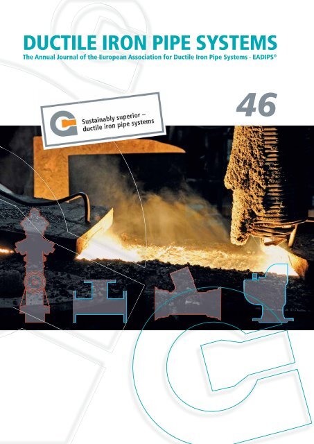
DUCTILE IRON PIPE SYSTEMS<br />
The Annual Journal of the European Association for Ductile Iron Pipe Systems · EADIPS ®<br />
46
Subjects and authors<br />
4 Letter from the editor<br />
5 Abstracts<br />
A modern material with a tradition<br />
8 Ductile iron pipe systems: sustainably superior<br />
by Ulrich Pässler<br />
DN 500 culvert pipeline for sewage<br />
13 Ductile iron pipes across the river Main<br />
guarantee safety and security in the long term<br />
by Stephan Hobohm and Heinz-Jörg Weimer<br />
DN 700 pipeline for uncontaminated wastewater<br />
19 Pile foundations for a pipeline of ductile iron pipes below<br />
the water table carrying uncontaminated wastewater<br />
by Roger Saner<br />
Newly installed – A DN 800 pipeline on pile foundations<br />
24 The municipality of Kutzenhausen – New pipes for ducting the Schüttgraben,<br />
a DN 800 pipeline on pile foundations<br />
by Simon Hähnlein and Manfred Schmied<br />
Renovation with DN 200 and DN 300 butterfly valves<br />
28 Installation of butterfly valves in plant equipment<br />
at the Bad Zwischenahn waterworks<br />
by Tim Hobbiebrunken<br />
Rubber gaskets for ductile iron pipe systems<br />
30 Which came first – the pipe or the seal?<br />
by Felice Pavan<br />
The new EN 545 – Impact on practical planning and design<br />
33 The impact of the new EN 545 on practical planning<br />
and design for ductile iron drinking water pipelines<br />
by Jürgen Rammelsberg<br />
Laying of new DN 100, DN 150 and DN 200 pipelines<br />
38 Re-organization of the Wertheim water supply system –<br />
Feeder pipeline to the Eichel/Hofgarten district<br />
by Erich Amrehn und Frieda Elenberger<br />
A DN 200, PFA 40 pressure pipeline for a drinking water power station<br />
42 Generating electricity by water power –<br />
An important contribution to the phasing out of atomic energy<br />
by Andreas Schütz<br />
2<br />
FGR® / EADIPS® 46
Subjects and authors<br />
A DN 400 culvert pipeline<br />
45 Culvert pipeline under the river Traun near Linz<br />
High performance by ductile iron pipe systems<br />
by Ingo Krieg<br />
A DN 500 trunk water main<br />
48 Zweckverband Gruppenwasserwerk Dieburg supply utility –<br />
Southern trunk water main from Hergershausen to Gross-Zimmern<br />
by Heinz-Jörg Weimer<br />
DN 500 press-pull technique<br />
51 World premiere at WASSER BERLIN INTERNATIONAL 2011 –<br />
The press-pull technique with soil removal<br />
by Stephan Hobohm und Franz Schaffarczyk<br />
The horizontal direction drilling technique – DN 700<br />
59 Germany’s biggest HDD project, using DN 700 ductile iron pipes<br />
by Lutz Rau<br />
A DN 500 penstock pipeline<br />
65 A DN 500 penstock pipeline pulled in straight through a mountain<br />
by Andreas Moser<br />
DN 80 to DN 250 snow-making systems<br />
69 The operators’ association Liftverbund Feldberg makes sure of snow<br />
by Stefan Wirbser, Christian Weiler and Alexander Bauer<br />
Driven ductile iron piles<br />
73 25 years of driven ductile iron piles<br />
by Jérôme Coulon and Erich Steinlechner<br />
79 Imprint<br />
80 Logos of full members of the FGR®/EADIPS®<br />
80 Logos of sponsoring members of the FGR®/EADIPS®<br />
81 A note from the Editor<br />
DUCTILE IRON PIPE SYSTEMS 3
Letter from the editor<br />
Dear readers,<br />
at the WASSER BERLIN INTERNATIONAL<br />
2011 international trade fair, the Fachgemeinschaft<br />
Guss-Rohrsysteme (FGR®) e. V. /<br />
European Association for Ductile Iron Pipe<br />
Systems · EADIPS® and its member companies<br />
who were exhibiting at the fair, briefed the professionals<br />
attending about what ductile iron<br />
pipe systems are capable of doing for them in<br />
the various applications the systems have in the<br />
water industry.<br />
These include not only the traditional fields of<br />
water supply and sewage disposal, but also more<br />
recent applications to high-pressure systems<br />
such as trunk mains for water, penstock pipelines<br />
and pipelines for snow-making systems. Some<br />
notable advances in trenchless installation using<br />
ductile iron pipe systems were given public recognition<br />
by the conferring of the German Society<br />
for Trenchless Technology’s GSTT Award 2011.<br />
Prize-winners included the press-pull technique<br />
with soil removal (2 nd prize) and an HDD installation<br />
operation in Berlin (3 rd prize); you can find<br />
articles on these in this issue of the Journal.<br />
Sustainability is one aspect of all the installation<br />
operations carried out. I have already reported<br />
on this subject in issue 45.<br />
4<br />
In making this assertion, the FGR®/ EADIPS®<br />
substantiates its claim that, from the point of<br />
view of sustainability, ductile iron pipe systems<br />
are economically, environmentally and technically<br />
superior. The technical articles in this issue<br />
will confirm this claim.<br />
I hope you will find plenty to enjoy in the new<br />
46 th issue of DUCTILE IRON PIPE SYSTEMS.<br />
Yours sincerely,<br />
Raimund Moisa<br />
FGR® / EADIPS® 46
Abstracts<br />
Ductile iron pipe systems:<br />
sustainably superior<br />
Ulrich Pässler ........................................................8<br />
A particularly important consideration for capital<br />
investments in supply infrastructure is the<br />
technical operating life of the items installed.<br />
No pipe material is a match for cast iron in this<br />
respect, because it has already been used in<br />
the supply of drinking water for several centuries.<br />
The sustainability of ductile cast iron pipe<br />
systems from the environmental and economic<br />
points of view is demonstrated; additionally it’s<br />
increasing use in trenchless installation techniques<br />
and in high-pressure applications is<br />
considered.<br />
Ductile iron pipes across the river Main<br />
guarantee safety and security in the long term<br />
Stephan Hobohm and Heinz-Jörg Weimer .........13<br />
The sewage from a million people in the city<br />
of Frankfurt am Main is treated in two treatment<br />
plants. Because of the topography, pressure<br />
pipelines have to be used to transport the<br />
sewage. For increased reliability of operation,<br />
a pressure pipeline crossing the river Main<br />
needed another pipeline in parallel. The planning<br />
and selection of the material for the installation<br />
of the culvert pipeline required under the<br />
river Main, using ductile iron pipes installed in<br />
an open trench is described as: a good lesson in<br />
thorough planning as a prerequisite for a successful<br />
installation.<br />
Pile foundations for a pipeline of ductile iron pipes<br />
below the water table carrying uncontaminated<br />
wastewater<br />
Roger Saner .........................................................19<br />
Ground with hardly any bearing capacity yet<br />
still highly corrosive, a pipeline zone below the<br />
water table, and topography giving only a very<br />
slight gradient – hardly the conditions under<br />
which you would expect to install a non-pressurised<br />
wastewater pipeline able to operate<br />
successfully in the long term. Yet it has been<br />
done with vonRollgeoecopur ductile iron pipes!<br />
They had to have pile foundations so that the<br />
gradient, slight anyway at < 3‰, would not be<br />
jeopardised by settlement.<br />
The municipality of Kutzenhausen –<br />
New pipes for ducting the Schüttgraben,<br />
a DN 800 pipeline on pile foundations<br />
Simon Hähnlein and Manfred Schmied ..............24<br />
Sometimes in a relatively small operation a<br />
number of individual and difficult problems<br />
may arise simultaneously, for example: when a<br />
stream is ducted into pipes which are dilapidated<br />
and have to be replaced; in ground with inadequate<br />
bearing capacity, below a road carrying<br />
heavy goods traffic. After a survey of the ground,<br />
it was possible to make a decision on an alternative<br />
route and that in turn provided the technical<br />
solution: the new pipeline of DN 800 ductile iron<br />
pipes for ducting the stream was given foundations<br />
formed by driven ductile iron piles.<br />
Installation of butterfly valves in plant<br />
equipment at the Bad Zwischenahn waterworks<br />
Tim Hobbiebrunken .............................................28<br />
Butterfly valves, may be less spectacular than<br />
the pipes and are often not seen, but that is why<br />
it is all the more important for them to operate<br />
reliably. The waterworks has had a varied<br />
history, which began when it supplied drinking<br />
water to a military airfield during the Third<br />
Reich. Today it is a vital resource in what is now<br />
the peaceful and prosperous spa town of Bad<br />
Zwischenahn. Ductile iron butterfly valves are<br />
the guarantee for a safe and secure supply of<br />
drinking water.<br />
Which came first – the pipe or the seal?<br />
Felice Pavan .........................................................30<br />
It is amazing how materials as different as<br />
iron and rubber have developed; in the case<br />
of ductile iron pipelines the development has<br />
sometimes gone on in parallel. This is because<br />
pipelines for drinking water and sewage are<br />
important infrastructures, which all communities<br />
with flourishing economies need.<br />
DUCTILE IRON PIPE SYSTEMS 5
The impact of the new EN 545 on<br />
practical planning and design<br />
for ductile iron drinking water pipelines<br />
Jürgen Rammelsberg ...........................................33<br />
Having introduced pressure classes for pipes<br />
not subject to longitudinal forces, EN 545:2010,<br />
the new product standard for ductile iron drinking<br />
water pipes, still does not contain a practical<br />
solution for dealing with and marking the<br />
pipe system which has joints restrained against<br />
longitudinal forces. With such joints, the allowable<br />
operating pressure is generally appreciably<br />
lower than the pressure given by the pressure<br />
class. In an association standard of its own, the<br />
FGR®/ EADIPS® will shortly be proposing a<br />
practicable procedure for dealing with and an<br />
unmistakable marking for these pipes, to cover<br />
the period until EN 545 is revised.<br />
Re-organization of the Wertheim<br />
water supply system – Feeder pipeline<br />
to the Eichel/Hofgarten district<br />
Erich Amrehn and Frieda Elenberger ................38<br />
Changes to official rules and regulations are<br />
sometimes the reason for an existing supply<br />
network being re-organized and for new and<br />
better quality water being distributed at a lower<br />
cost. This is what happened in Wertheim where,<br />
although the constraints were difficult, a further<br />
pressure zone was even added. The selection<br />
of the material was exemplary: in rocky<br />
ground, rugged ductile iron pipes and fittings<br />
are the ideal prerequisites for a viable longterm<br />
investment.<br />
Generating electricity by water power –<br />
An important contribution to the phasing<br />
out of atomic energy<br />
Andreas Schütz ...................................................42<br />
Mountainous regions in Switzerland are often<br />
blessed by considerable differences in height<br />
between intake structures at springs and the<br />
drinking water reservoir serving a local community.<br />
What are referred to as drinking water<br />
power stations can kill two birds with one stone,<br />
the local water supply is combined with the<br />
local generation of green electricity. With guaranteed<br />
feed-in tariffs, the installation of the station<br />
soon pays for itself. Ductile iron pipes with<br />
restrained push-in joints are equal to the high<br />
operating pressures, are easy to install even in<br />
difficult terrain, and their robust material will<br />
withstand any external loads.<br />
6<br />
Culvert pipeline under the river Traun near Linz<br />
High performance by ductile iron pipe systems<br />
Ingo Krieg ............................................................45<br />
Ductile iron pipes as problem solvers – that is<br />
how they are often seen, because they become a<br />
talking point in spectacular special cases. Often<br />
forgotten though are the many kilometres of<br />
ductile iron pipeline which go into the ground<br />
unnoticed under “bread and butter” contracts<br />
and quietly do their duty there for decades. But<br />
the real source of pride to those involved in the<br />
installation is of course problems successfully<br />
overcome, as here on the Traun where there<br />
were several types of river crossing – an<br />
instructive example of the universality of ductile<br />
iron pipe systems.<br />
Zweckverband Gruppenwasserwerk<br />
Dieburg supply utility – Southern trunk water main<br />
from Hergershausen to Gross-Zimmern<br />
Heinz-Jörg Weimer .............................................48<br />
Often there is not an easy solution for a technically<br />
demanding problem. Things are deferred<br />
and the problem becomes more urgent.<br />
Restricted and complicated routes for pipelines<br />
in which other construction and installation<br />
companies and agencies have a say, may be<br />
particularly critical in this case. Almost all the<br />
practical problems arising with pipelines can be<br />
solved with ductile iron pipes – easily, inexpensively<br />
and for the long term. Here is a project<br />
report which is typical of many similar cases.<br />
World premiere at WASSER BERLIN INTERNATIONAL<br />
2011 – The press-pull technique with soil removal<br />
Stephan Hobohm and Franz Schaffarczyk ........51<br />
As so often in the past, Berlin has been the<br />
scene of an innovation in pipeline installation.<br />
The press-pull technique, a tried and trusted<br />
trenchless pipeline replacement technique,<br />
had to be modified because the soil displacement<br />
needed for the upsizing required for the<br />
new pressure pipeline was impossible with the<br />
given height of cover. The press-pull technique<br />
was therefore expanded to include soil removal,<br />
a reliable way of preventing a hump from being<br />
formed above the pipeline on the surface of the<br />
ground. The new technique made its debut on<br />
the Construction Site Day which formed part of<br />
the WASSER BERLIN INTERNATIONAL 2011<br />
fair. On 07.12.2011, this project was awarded 2 nd<br />
prize under the GSTT Award 2011.<br />
FGR® / EADIPS® 46
Germany’s biggest HDD project,<br />
using DN 700 ductile iron pipes<br />
Lutz Rau ...............................................................59<br />
A new record in Germany: on a strip of land on<br />
the banks of the river Havel where access was<br />
difficult, a 490 m long DN 700 pipeline for raw<br />
water has been installed using the horizontal<br />
direction drilling technique.<br />
The 82 pipes with BLS® push-in joints were<br />
assembled and pulled in, on an enclosed assembly<br />
ramp, in 34 hours.<br />
The onset of severe winter weather and high<br />
water levels interrupted the work for two<br />
months but the project was still completed<br />
within the time scheduled.<br />
The project was awarded 3 rd prize at the GSTT<br />
Awards 2011.<br />
A DN 500 penstock pipeline pulled in straight<br />
through a mountain<br />
Andreas Moser ....................................................65<br />
The encouragement to generate renewable<br />
energy which is provided by fixed feed-in tariffs,<br />
often results in existing small hydroelectric<br />
power stations looking at ways of increasing<br />
their capacity. Though it is only nine years old,<br />
this was achieved at the Tasser power station in<br />
South Tyrol, whose output has been boosted by<br />
60 % by lengthening the existing penstock pipeline<br />
by 1,225 m and thus increasing the pressure<br />
in it from 15 bars to 28 bars. The installation of<br />
the extra length was extremely difficult, involving<br />
drilling through 174 m of rock, but it meant<br />
that the material for the penstock pipeline was<br />
easy to select: ductile iron pipe systems are<br />
equal to any challenge.<br />
The operators’ association Liftverbund Feldberg<br />
makes sure of snow<br />
Stefan Wirbser, Christian Weiler and<br />
Alexander Bauer .................................................69<br />
Ductile iron pipes for snow-making systems –<br />
this is an application which is showing satisfying<br />
levels of growth. The external conditions,<br />
steep runs of pipe, difficult ground, routes<br />
which are difficult to access, and high operating<br />
pressures: these are challenges which are<br />
just right for ductile iron pipe systems. This has<br />
once again been demonstrated on the Feldberg<br />
mountain in the Black Forest.<br />
25 years of driven ductile iron piles<br />
Jérôme Coulon and Erich Steinlechner ..............73<br />
The 25 year success story of ductile iron driven<br />
piles – from their invention in a Swedish pipe<br />
foundry to today’s 5 million metres of driven<br />
piles – is inconceivable without the properties of<br />
ductile cast iron, without the production of virtually<br />
monolithic foundation piles of all lengths<br />
from individual to mass-produced pieces, and<br />
without the minimal installation and site costs.<br />
Even very strict clients such as SBB (Swiss<br />
Federal Railways) use ductile iron driven piles<br />
as foundations for their network structures –<br />
sometimes while services continue running.<br />
DUCTILE IRON PIPE SYSTEMS 7
A modern material with a tradition<br />
Ductile iron pipe systems: sustainably superior<br />
by Ulrich Pässler<br />
1 Introduction – the development history<br />
Around 150 years ago in Europe, the infrastructure<br />
for supplying towns and cities with gas<br />
and water was laid almost entirely in cast iron<br />
pipes. A large proportion of today’s supply networks<br />
still date from that time. Over the years,<br />
the development of crucial aspects of the cast<br />
iron pipe system has continued: production<br />
processes have adapted to meet the increased<br />
requirements for dimensional accuracy, reductions<br />
in wall thickness and cost-effectiveness,<br />
and joints have become safer, more reliable and<br />
easier to connect. The triumphal progress of<br />
the cast iron pipe from the grey cast iron pipe<br />
of those days to the ductile iron pipe of modern<br />
times is a reflection of the story of industry itself<br />
and is an impressive demonstration of the qualities<br />
of ductile cast iron and of the many obvious<br />
advantages it has. There is no pipe material that<br />
can provide such clearly demonstrable proof of<br />
its durability as ductile cast iron.<br />
Over the years, a series of other materials apart<br />
from ductile cast iron have been developed<br />
for pipes carrying drinking water and sewage<br />
but closer inspection shows none of them<br />
to have any major advantages over this traditional<br />
material. On the contrary, when it comes<br />
to reliability, durability, resistance to damage<br />
and sustainability, there is at the moment no<br />
pipe material which can offer higher standards<br />
of performance than ductile iron. This is just as<br />
true of pipes for pipelines for drinking water,<br />
where the very highest quality and purity has to<br />
be guaranteed, as it is of ones used in pipelines<br />
for sewage, which has to be transported safely<br />
to treatment and purification plants. And it is<br />
equally true of fittings and valves of ductile iron,<br />
whose reliability helps with the installation of<br />
pipelines and makes them sustainably safe.<br />
8<br />
2 Clear advantages in term of cost<br />
Particularly in the very recent past, certain competing<br />
materials have tried to make out a case<br />
for themselves as having an advantage in terms<br />
of price. And in times when budgets are tight<br />
this supposed advantage has tempted municipalities<br />
and supply companies to make decisions<br />
that look only at the short term. However,<br />
on closer inspection the price-based argument<br />
proves to be deceptive because effects<br />
which only become apparent in the medium to<br />
long term are often ignored and the responsibility<br />
owed to future generations is thus often<br />
forgotten.<br />
It has been shown by, for example, studies<br />
comparing the costs of plastic and ductile iron<br />
pipes over a period in use of 15 years that, as<br />
from a nominal size of DN 200, if not a smaller<br />
one, ductile iron pipes quite clearly have major<br />
advantages and that, as the sizes become larger,<br />
so do they become increasingly superior.<br />
At a nominal size of DN 400, the advantage in<br />
terms of cost of using ductile iron pipes over<br />
using plastic ones can be calculated as more<br />
than 20% over the period mentioned [1]. This<br />
advantage is achieved by, amongst other things,<br />
more efficient installation.<br />
Ductile iron pipes, with their easily connected<br />
joints, can be installed quickly and<br />
easily regardless of the weather. Polyethylene<br />
pipes on the other hand, whose joints have to be<br />
welded, involve considerably higher expenditure<br />
on, amongst other things, the skilled and<br />
certified personnel required for the welding.<br />
Also, dry weather is needed for the welding, and<br />
this means an increase in costs for the welding<br />
when the weather is bad and thus a decrease in<br />
the efficiency of installation.<br />
FGR® / EADIPS® 46
Fig. 1<br />
Ductile iron pipes do not require a sand bedding<br />
The rugged ductile iron pipe system does not<br />
require a sand bedding (Fig. 1). Depending on<br />
the external protection, the material excavated<br />
from the trench can be re-used for installation,<br />
even at grain sizes up to 100 mm [2].<br />
With plastic pipes, there is still some contention<br />
on this point: whereas under Appendix G<br />
to DVGW Arbeitsblatt W 400-2 [2] the grain size<br />
is limited to 40 mm (round grains) for polyethylene<br />
pipes > DN 200, according to [3] plastic<br />
pipes are installed in a bed of sand to protect<br />
them against external damage under the current<br />
rules. Without this bed of sand, some<br />
pipes would be very highly stressed by external<br />
loads or changes in pressure [3]. Hence, the<br />
nature of the material surrounding the pipe<br />
has to be such that the pressurised pipe carrying<br />
the medium is protected against external<br />
damage. This generates extra costs for the material<br />
and its transportation, extra costs which are<br />
un necessary with ductile iron pipe systems.<br />
Under normal installation conditions and if<br />
restrained joints are used, ductile iron pipes<br />
manage without concrete thrust blocks –<br />
another advantage which can impact on the<br />
costs of the pipeline (Fig. 2).<br />
In the long term, as the studies mentioned<br />
above and also the damage statistics compiled<br />
by the DVGW (German Technical and<br />
Scientific Association for Gas and Water)<br />
have shown, ductile iron pipes also have<br />
considerably lower fault and damage rates.<br />
The DVGW Damage Statistics for Water [4]<br />
(years surveyed 1997 to 2004, covering the whole<br />
of the Federal Republic of Germany) show a<br />
damage rate (number of damaged points per<br />
100 km) of 4 for ductile iron pipes for 2004. For<br />
Fig. 2<br />
A ductile iron pipe with a cement mortar coating and a<br />
restrained push-in joint<br />
HDPE pipes the rate was 50 % higher, namely 6.<br />
With ductile iron pipes the proportion of damaged<br />
points caused by external effects was only<br />
about 5 % whereas it was approximately 18%<br />
with HDPE.<br />
There could hardly be a clearer demonstration<br />
of the advantages of ductile iron pipes. A<br />
decision to use ductile iron pipelines therefore<br />
produces an investment whose advantages are<br />
sustainable, because there is also a saving on<br />
the cost of maintenance and repairs in the long<br />
term. Added to this are “incalculable” advantages<br />
from the environmental and hygienic<br />
points of view which make the ductile iron pipe<br />
a superior alternative investment even in very<br />
small nominal sizes.<br />
3 Safety below ground.<br />
Responsibility for the environment<br />
The raw material used for ductile cast iron is<br />
pre-sorted recycled steel scrap. In contrast to<br />
plastic pipes, virtually no primary or fossil raw<br />
materials have to be used for ductile cast iron,<br />
thus reducing CO 2 emissions and the demands<br />
made on natural resources. Ductile iron<br />
pipes make a positive contribution to the<br />
environment.<br />
An important factor in any environmental<br />
and hygienic consideration is ductile<br />
cast iron’s impermeability to diffusion. For<br />
the protection of drinking water and for sewage<br />
pipelines, this is an unbeatable argument.<br />
Where the diffusion of chlorinated hydrocarbons<br />
for example is possible, polyethylene pipes<br />
are around 1,000 times more permeable than<br />
ductile iron pipes [5].<br />
DUCTILE IRON PIPE SYSTEMS 9
What is more, ductile iron pipes have a guarantee<br />
of hygienic and environmentally friendly<br />
operation in the form of their linings (polyurethane<br />
to EN 15655 [6] and mortar based on<br />
blast furnace cement for the supply of drinking<br />
water [7] or mortar based on high-alumina<br />
cement for the disposal of sewage [8]).<br />
4 Durability:<br />
Avoidance of future expenditure<br />
There is no other pipe material which can provide<br />
such convincing practical proof of its<br />
durability, and therefore of the safety which it<br />
maintains for generations, as ductile iron. The<br />
technical operating life of ductile iron pipes is<br />
up to 140 years. If ductile iron pipes with their<br />
high-grade coatings as follows<br />
■ a cement mortar coating (ZM-U) to EN<br />
15542 [9] and<br />
■ polyurethane (PUR) to EN 15189 [10]<br />
are taken as a basis, they provide a particularly<br />
impressive and emphatic confirmation of<br />
this long operating life. A systematic study has<br />
been made in which the outer surfaces of pipes<br />
which had been in operation for periods of up to<br />
32 years were examined and samples for examination<br />
under DIN 50929, part 3 [11] were taken<br />
of the native soils and of the bedding materials<br />
used in the respective cases. At all the test digs,<br />
it was found that, after being in use for from<br />
25 to 32 years, pipes coated with cement mortar<br />
were in a virtually good as new state and were<br />
not showing any damage due to corrosion [12].<br />
Similar studies to provide practical proof of the<br />
long-term resistance of the polyurethane coating<br />
are going on in Switzerland. Two runs of<br />
test pipeline, which are continuously monitored<br />
by the SGK (Swiss Society for Corrosion<br />
Protection), have been operating for more than<br />
20 years in Zurich. The protective potentials of<br />
the polyurethane coated pipes and their contact<br />
resistances with the ground are measured in<br />
different soils. In all the beddings studied, these<br />
field studies show constant good performance<br />
on the part of ductile iron pipes coated with<br />
polyurethane [13].<br />
From all these studies, it can be concluded<br />
that these ductile iron pipe systems with<br />
high-grade coatings, will undoubtedly<br />
achieve a technical operating life of 100 to<br />
140 years.<br />
10<br />
A glance at the pre-industrial era reveals<br />
another impressive fact: In 1783, Clemens<br />
Wenceslaus, the Archbishop-Elector of Trier,<br />
gave instructions for a water pipeline to be<br />
laid to supply the public wells of the town of<br />
Koblenz. This pipeline, known as the Metternich<br />
water pipeline, consisted of socketed cast<br />
iron pipes of a laying length of 1.5 metres and<br />
a diameter of 80 millimetres. When, after more<br />
than 150 years, this pipeline was exposed in<br />
1934, it was found that the material of the<br />
pipes was still in excellent condition after their<br />
long time in operation. The then Lord Mayor<br />
of Koblenz confirmed this in an official letter<br />
to the “Deutscher Gußrohr-Verband” [14],<br />
today’s europäische Fachgemeinschaft Guss-<br />
Rohr systeme (FGR®) e. V. / European Association<br />
for Ductile Iron Pipe Systems · EADIPS®,<br />
www. eadips.org.<br />
Polyethylene pipes are assumed to have an<br />
operating life of around 60 years. That is less<br />
than half the demonstrable working life of ductile<br />
iron pipes. This means that re-investment<br />
and rehabilitation budgets can be set at an<br />
appreciably lower level when ductile iron pipes<br />
are used.<br />
5 Trenchless installation techniques and pipelines<br />
subject to high stresses<br />
Trenchless installation techniques have now<br />
become very important all over Europe. To avoid<br />
site noise and obstacles to traffic in inner-city<br />
areas and to allow crossings to be made under<br />
obstructions such as roads or rivers, trenchless<br />
installation techniques are now indispensable<br />
when pressure pipelines have to be replaced.<br />
They are low-cost techniques which are kind<br />
to the environment. There was been a close<br />
connection between their development and<br />
the ductile iron pipe and its joints and types of<br />
external protection. Because of their ability to<br />
carry high mechanical loads, ductile iron pipes<br />
with restrained joints are very much superior to<br />
pipes of any other material for trenchless installation<br />
(Fig. 3), a superiority which is also seen<br />
in the allowable tractive forces which can be<br />
used with them (Fig. 4).<br />
FGR® / EADIPS® 46
Fig. 3<br />
A DN 125 push-in joint being connected on a burst lining<br />
project<br />
Fig. 4<br />
Allowable tractive forces on pipelines in trenchless<br />
installation and replacement techniques<br />
This superiority is also apparent in other heavyduty<br />
applications. The strength of plastic pipes<br />
to resist pressure is limited and because of this<br />
they can be used to only a very limited extent, if<br />
at all, for turbine pipelines for example, which<br />
have to withstand high pressures and generally<br />
have to be installed in topographically difficult<br />
terrain.<br />
Because of the properties of their material and<br />
the different types of external protection available,<br />
ductile iron pipes on the other hand can<br />
be installed without any problems even in rocky<br />
terrain and are even suitable for operating pressures<br />
of more than 100 bars. It is not only in the<br />
case of snow-making systems, which are generally<br />
located in mountainous terrain, and in the<br />
case of pipelines for fire extinguishing water,<br />
which call for a fireproof material for the pipes,<br />
that these advantages become clear. They also<br />
Fig. 5<br />
Ductile iron fittings and valves<br />
apply in principle to any ductile iron pressure<br />
pipeline used in municipal water supply, which<br />
needs good safety margins.<br />
6 To sum up<br />
Ductile iron is a material which can be used in<br />
any pipeline and water management applications<br />
and one which, due to its superior technical<br />
properties, the cost-saving technology used<br />
for its coatings and joints, and the full range of<br />
fittings and valves which is available (Fig. 5), is<br />
able to guarantee long-term safety wherever it<br />
is used. Though a traditional material, cast iron<br />
is in fact more up to date than ever because it<br />
meets the demands of the future for the economical<br />
use of resources and for long-term cost<br />
advantages and therefore for true sustainability.<br />
References<br />
[1] Wegener, Th. and Böge, M: Wirtschaftlichkeitsuntersuchungen<br />
an Rohrleitungen,<br />
GUSSROHR-TECHNIK 41 (2007), p. 45<br />
[2] DVGW-Arbeitsblatt W 400-2<br />
Technical rules of water distribution systems<br />
Part 2: Installation and testing<br />
2004-09<br />
[3] DVGW Technologie Report Nr. 4/2008:<br />
Kunststoffmaterialien in der Gas- und<br />
Wasserversorgung<br />
[4] Neihues, Berthold: DVGW-Schadensstatistik<br />
Wasser. Ergebnisse aus den Jahren 1997<br />
bis 2004<br />
energie | wasser praxis 10 (2006), pp. 18–23<br />
DUCTILE IRON PIPE SYSTEMS 11
[5] Ministerium für Ernährung, Landwirtschaft,<br />
Umwelt und Försten des Landes<br />
Baden-Württemberg (publishers): Umgang<br />
mit leichtflüchtigen chlorierten und aromatischen<br />
Kohlenwasserstoffen – Leitfaden.<br />
H. 15, December 1984,<br />
reprinted December 1986<br />
[6] EN 15655<br />
Ductile iron pipes, fittings and accessories –<br />
Internal polyurethane lining for pipes and<br />
Fittings –<br />
Requirements and test methods<br />
2009<br />
[7] EN 545<br />
Ductile iron pipes, fittings, accessories and<br />
their joints for water pipelines –<br />
Requirements and test methods<br />
2010<br />
[8] EN 598<br />
Ductile iron pipes, fittings, accessories and<br />
their joints for sewerage applications –<br />
Requirements and test methods<br />
2009<br />
[9] EN 15542<br />
Ductile iron pipes, fittings and accessories –<br />
External cement mortar coating for pipes –<br />
Requirements and test methods<br />
2008<br />
[10] EN 15189<br />
Ductile iron pipes, fittings and accessories –<br />
External polyurethane coating for pipes –<br />
Requirements and test methods<br />
2006<br />
12<br />
[11] DIN 50929-3<br />
Corrosion of metals; probability of corrosion<br />
of metallic materials under external<br />
corrosion conditions; pipelines and structural<br />
component parts in soil and water<br />
1985-09<br />
[12] Rink, W.: Examination of ductile iron pipes<br />
with cement mortar coating after a period<br />
of three decades in operation,<br />
FGR® / EADIPS® DUCTILE IRON PIPE<br />
SYSTEMS 45 (2011), p. 29<br />
[13] SGK (Swiss Society for Corrosion Protection),<br />
unpublished report 07’044-2, eco pur-<br />
Rohre in der Grossmann-Strasse,<br />
Mess ergebnisse bis 2007, Zurich 27.07.07<br />
[14] Gußeiserne Druckrohre – Entwicklung ·<br />
Herstellung · Verwendung<br />
Published by: Fachgemeinschaft Gußeiserne<br />
Rohre, Cologne<br />
1954<br />
Author<br />
Dipl.-Kfm. Ulrich Pässler<br />
Chairman of the Board<br />
of the Fachgemeinschaft Guss-Rohrsysteme<br />
(FGR®) e. V. / European Association for Ductile<br />
Iron Pipe<br />
Systems · EADIPS®<br />
Im Leuschnerpark 4<br />
64347 Griesheim, Germany<br />
phone: +49 (0)61 55/6 05-2 25<br />
E-mail: info@eadips.org<br />
FGR® / EADIPS® 46
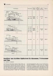
DN 500 culvert pipeline for sewage<br />
Ductile iron pipes across the river Main<br />
guarantee safety and security in the long term<br />
by Stephan Hobohm and Heinz-Jörg Weimer<br />
The experts at Frankfurt’s drainage and sewage<br />
disposal utility Stadtentwässerung Frankfurt<br />
am Main (SEF) called it a special event such as<br />
happens only once a decade. On 10 March 2011<br />
a new culvert pipeline for sewage was pulled<br />
through the bed of the river Main.<br />
Since June 2011 the sewage from the town of<br />
Kelsterbach has been flowing through it to the<br />
sewage treatment plant at Frankfurt-Sindlingen.<br />
SEF is a Frankfurt-owned municipal utility and<br />
it has invested 3.3 million Euros in this new<br />
267.5 metre long pipeline, including the connections<br />
to the existing pipelines on both sides of<br />
the Main.<br />
1 The situation at the outset<br />
The sewage from almost a million people<br />
in the Frankfurt urban area – which means,<br />
in dry weather, around 300,000 m 3 a day or<br />
15,000 tanker-lorry loads flows into the sewers<br />
and to the Niederrad/Griesheim and Sindlingen<br />
sewage treatment plants. There is another<br />
treatment plant in the town of Bad Vilbel, but<br />
the nature of the topography means that only<br />
the sewage from Nieder-Erlenbach flows to that.<br />
However, it is not just the sewage generated<br />
in the Frankfurt urban area; also connected to<br />
Frankfurt’s sewer network are the Abwasserverband<br />
Main-Taunus and Westerbachverband<br />
sewage utilities and also five other towns<br />
(Offenbach, Kelsterbach, Neu Isenburg, Steinbach,<br />
and the Bischofsheim district of Maintal).<br />
Previously, a pumping station on the left bank<br />
of the Main had pumped the sewage from Kelsterbach,<br />
a town on the south-western edge of<br />
Frankfurt, to the treatment plant in Sindlingen<br />
through a DN 500 size pressure pipeline.<br />
The maximum pumping rate was about 240 L/s.<br />
After about 450 m, this pressure pipeline<br />
crosses the Main at the point where the Bonnemühle<br />
mill belonging to the Okriftel district<br />
of Hattersheim is situated and on the right bank<br />
of the Main runs for another 2,250 m to where<br />
it opens into a gravity sewer at the treatment<br />
plant. Nowhere along the entire length of some<br />
2,700 m are there any possibilities of a diversion<br />
or any retention facilities.<br />
The pipeline was laid in 1981. At the last inspection<br />
carried out under the German Sewage<br />
Monitoring Regulations there was found to be<br />
slight damage and the SEF therefore felt itself<br />
compelled to act. Repairing the damage would<br />
necessarily have involved withdrawing the<br />
pressure pipeline from service for a time and<br />
this would not been possible without a replacement<br />
for the pipeline crossing the Main.<br />
To ensure the reliability of the pressure pipeline<br />
and also to enable strategic action to be taken in<br />
the event of a fault, a new pressure pipeline had<br />
to be installed (Fig. 1).<br />
Main-Taunus district<br />
town of Hattersheim<br />
Okriftel<br />
Existing<br />
pressure pipeline<br />
New Main<br />
culvert pipeline<br />
Kelsterbach<br />
pumping station<br />
Sindlingen sewage<br />
treatment plant<br />
Gross-Gerau<br />
district Town of<br />
Kelsterbach<br />
Fig. 1:<br />
Path followed by the sewage pressure pipeline and<br />
position of the new culvert pipeline<br />
DUCTILE IRON PIPE SYSTEMS 13
2 The planning phase<br />
As part of a feasibility study, a variety of options<br />
for the Main crossing were examined involving<br />
different routes and different laying techniques<br />
and materials. The comparison was therefore<br />
confined to the section of pipeline between<br />
the left and right banks of the Main and to<br />
the ascending sections on the two sides running<br />
to the connections to the existing pipeline.<br />
An open-trench crossing of the Main was<br />
found to be the simplest solution. It meant that<br />
only a trench, in which the pipeline would subsequently<br />
find a home, would have to be excavated<br />
in the bed of the river. This technique had<br />
the following advantages:<br />
■ very minor interference to nature and the<br />
environment,<br />
■ a route of comparatively short length,<br />
■ low installation costs,<br />
■ a technique which presented only minimal<br />
risks.<br />
For the open-trench crossing of the Main, the<br />
trench for the culvert pipeline would be dug by<br />
the dry or dredging method of excavation, and<br />
the culvert pipeline would be installed and the<br />
trench refilled. It is true that major incursions<br />
would have to be made into the surface of the<br />
riverbed, but this is the technique where the<br />
laying soil poses the fewest risks. Even obstacles<br />
such as boulders, remnants of structures, etc.<br />
could be removed so to make sure that the culvert<br />
pipeline could be laid.<br />
Once the laying technique had been decided<br />
on, the usual laborious business of obtaining all<br />
the consents and approvals followed. The districts,<br />
municipalities and other authorities having<br />
given the go-ahead, there was one more<br />
Fig. 2:<br />
A ductile iron sewer pipe with a BLS ® /VRS ® -T<br />
push-in joint<br />
14<br />
obstacle that had to be overcome: there are still<br />
bombs and shells from the Second World War<br />
lying on the bed of the Main. A check therefore<br />
had to be made to see whether there were still<br />
any dangerous leftovers that had to be removed.<br />
Areas of 4,500 m 2 in the Main and 500 m 2 on<br />
land and on the banks were searched. The<br />
divers came across all sorts of objects – bicycles<br />
and even mopeds – but luckily nothing of an<br />
explosive nature.<br />
In respect of the material, the client opted in the<br />
end for DN 500 ductile iron pipes to EN 598 [1]<br />
with BLS®/VRS®-T push-in joints and a cement<br />
mortar coating (ZM-U) to EN 15542 [2] (Fig. 2).<br />
The reasons for this decision included:<br />
■ short delivery times for pipes and fittings,<br />
■ quick and easy assembly,<br />
■ assembly is possible in all weathers<br />
(including frost and snow)<br />
■ maximum corrosion protection provided by<br />
a zinc coating and the ZM-U<br />
■ being economically attractive<br />
■ durability,<br />
■ maximum safety margins to deal with<br />
unplanned loads,<br />
■ proximity to manufacturer’s site (for technical<br />
support).<br />
In the course of wide-ranging technical consultancy<br />
meetings held by the pipe supplier’s<br />
Applications Engineering Division with Hülskens,<br />
the installing company from Wesel, all the<br />
details relating to the equipment specifications,<br />
the installation procedures and the leak testing<br />
were settled in full, in advance of the installation.<br />
In the light of the pipes to be used, the<br />
Hülskens company was then able to decide on<br />
and calculate the precise technical specifications<br />
for the design of the culvert pipeline. This<br />
showed the total weight of the culvert pipeline<br />
made up of the pipes, supporting structure and<br />
end sections to be some 82 t.<br />
The calculation of buoyancy showed there to be<br />
a safety factor of just on 1.3 during the installation<br />
phase (pipeline empty, no cover of riverbed<br />
material). The maximum tractive force<br />
to be expected, given by the weight of the culvert<br />
pipeline structure and the installation<br />
technique, was determined as 15.22 t so the<br />
planning included two cable winches each providing<br />
a tractive force of 16 t. The maximum<br />
tractive force occurs shortly before the end<br />
(fully pulled-in) position and is calculated from<br />
the total buoyant weight of the culvert pipeline<br />
multiplied by a coefficient of friction µ = 0.65.<br />
The overall tractive force was applied by the<br />
FGR® / EADIPS® 46
Fig. 3:<br />
Driving the sheet piling<br />
Fig. 4:<br />
Dredging work<br />
cable winches, via return pulleys, to a traction<br />
head which was connected to the structure supporting<br />
the culvert pipeline. This stopped any<br />
tractive forces from being transmitted to the<br />
pipeline itself.<br />
Another point in the actual planning for the<br />
work was the fixing of the minimum radiuses.<br />
The BLS®/VRS®-T push-in joint of DN 500 ductile<br />
iron sewer pipes allows an angular deflection<br />
of 3°. This gives a minimum radius of 115 m.<br />
The Hülskens company’s calculations showed<br />
the supporting structure to have a smallest<br />
allowable bending radius of 102 m. For safety’s<br />
sake, a minimum radius of 150 m was decided<br />
on for the line followed by the pipeline and for<br />
the digging of the trench floor and the pull-in<br />
ramp.<br />
Fig. 5:<br />
The supporting structure on rollers<br />
3 The installation phase<br />
3.1 Preparatory operations<br />
After the quite long planning phase described<br />
above, the installation work got underway in<br />
October 2010.<br />
Before the actual pulling-in, a trench some 2.5<br />
to 3 m deep and just on 150 m long was excavated<br />
across the Main. A special dredger which<br />
kept exactly to the minimum radius of 150 m<br />
preset for the floor of the trench was used for<br />
this. The spoil excavated from the trench was<br />
taken away by barge and was later re-used as<br />
backfill material. This was possible because of<br />
the external protection on the pipes (a cement<br />
mortar coating applied in the factory). Under<br />
EN 545 [3], ductile iron pipes with a ZM-U coating<br />
can be installed in soil of any desired corrosiveness,<br />
i.e. even below the bed of a river.<br />
The allowable maximum grain size of the backfill<br />
material is limited to 100 mm under DVGW-<br />
Arbeitsblatt W 400-2 [4] in this case. While the<br />
trench was being dredged, sheet piling was<br />
being driven on both sides of the Main and the<br />
launch and target pits and the pull-in ramp<br />
were being dug (Figs. 3 and 4). A directionchanging<br />
frame was installed in the target pit,<br />
by means of which the traction cable was passed<br />
from the two cable winches through the trench<br />
to the traction head on the structure supporting<br />
the pipeline. At the same time as these operations,<br />
a start was made on building the supporting<br />
structure and assembling the pipes.<br />
DUCTILE IRON PIPE SYSTEMS 15
3.2 Assembly of the culvert pipeline<br />
To minimise the pulling-in forces, the entire<br />
culvert pipeline including the supporting structure<br />
was assembled on rollers spaced 3 m apart<br />
(Fig. 5). The load-bearing capacity of each individual<br />
roller was 13 t. The supporting structure<br />
was laid along the tops of the rollers. The structure<br />
mainly consisted of a 1,000 mm wide traction<br />
plate at the bottom, two 100 mm high angles<br />
forming the edging formwork, and the ballasting<br />
concrete (1,000 mm x 100 mm). The ascending<br />
supporting structures for the end sections of the<br />
pipeline were welded on at the beginning and<br />
end (Fig. 6).<br />
Winter set in early with temperatures well<br />
below freezing and snow, but in spite of this<br />
the next step, the assembling of the pipes,<br />
got started on time, not least because of the<br />
advantage of ductile iron pipes being able to<br />
be installed regardless of the weather. Using<br />
Fig. 6:<br />
Ascending section and supporting structure<br />
Fig. 7:<br />
Cross-section of culvert pipeline<br />
16<br />
wooden saddles and steel straps, the DN 500<br />
ductile iron pipes were fastened to the concrete-filled<br />
supporting structure together with<br />
two DN 100 ductworks (Fig. 7). Ascending sections<br />
were formed at the two ends of the culvert<br />
pipeline because what would later be the<br />
connections to the on-shore pipelines were<br />
some 2.5 metres above its axis. The ends of the<br />
pipeline were closed off with fittings from the<br />
BLS®-/VRS®-T range (Fig. 8) and subsequent<br />
pressure testing could thus be carried out without<br />
any further shoring. The Vorwerk company<br />
of Halle/Saale, which has had plenty of experience<br />
with the laying of ductile iron pipes, was<br />
the contractor for the connection of the pipes.<br />
The actual assembly of the pipeline and its end<br />
sections took only three days. The severe frost<br />
and the high water level which followed (Fig. 9)<br />
stopped the pressure test from being carried out<br />
immediately but it did go off satisfactorily early<br />
in February.<br />
Fig. 8:<br />
Connecting a dead end<br />
Fig. 9:<br />
High water level<br />
FGR® / EADIPS® 46
Fig. 10:<br />
The traction head<br />
3.3 Pulling-in of the culvert pipeline<br />
As well as carrying the tractive forces, the supporting<br />
structure described not only ensured a<br />
stable position during the pulling-in but also<br />
gave added weight to stop the pipeline from<br />
floating up during the pulling-in. The traction<br />
head was fitted to the end of the supporting<br />
structure closer to the river (Fig. 10). Fastened<br />
in the traction head was a return pulley for the<br />
traction cable and the latter ran across the Main<br />
and over a direction-changing structure to the<br />
two cable winches (Fig. 11). Then, on 10 March<br />
2011, the time had come and the pulling-in<br />
could start. The pulling-in operation began<br />
dead on 10 a. m., watched by 100 or so interested<br />
spectators.<br />
Fig. 11:<br />
Looking from the direction-changing frame over the cable winches<br />
to the left bank of the Main<br />
The entire structure was pulled off the rollers<br />
towards the Main. The roller-equipped track<br />
ended about 20 m before the water line so the<br />
pipeline had to be pulled along the ground<br />
in this area. The front ascending section then<br />
began to slide into the water, to come to the surface<br />
again on the left bank of the Main some<br />
2.5 hours later. The traction force measured<br />
during the pulling-in operation was a maximum<br />
of 14 t.<br />
For safety reasons there was a ban on any navigation<br />
on the river on this day.<br />
Standard depth of cover Standard depth of cover � 1.2 m on land, � 2.0 m under the Main<br />
Pipes DN 500 ductile iron pipes to EN 598 [1] with BLS ® /VRS ® -T push-in joints and<br />
NBR TYTON ® gaskets to DIN 28603 [5]<br />
Coating Zinc coating (200 g/m2 ) plus cement mortar coating to EN 15542 [2]<br />
Lining Cement mortar lining based on high-alumina cement, to DIN 2880 [7]<br />
and EN 598 [1]<br />
Thickness of layer � 5.0 mm<br />
Protection for sockets ZM-U protecting sleeve<br />
Fittings DN 500 ductile iron fittings to EN 545 [3] with BLS ® /VRS ® -T push-in joints<br />
and NBR TYTON ® Table 1:<br />
Technical data in brief<br />
gaskets to DIN 28603 [5]<br />
Internal and external coatings Epoxy powder coating (� 250 µm) to EN 14901 [6]<br />
of fittings<br />
Installation time October 2010 to May 2011<br />
Cost of project 3.3 million Euros<br />
DUCTILE IRON PIPE SYSTEMS 17
4 Concluding work<br />
The pulling-in of the pipeline was still not the<br />
end of the operation. In addition to the pipeline<br />
itself, another 112 m of ductile iron pipes was<br />
installed on the left and right banks of the Main<br />
together with two manholes which included pig<br />
launcher/receivers. The pipeline can be cleaned<br />
in future from these. The connecting of the new<br />
pipeline to the existing one, and the backfilling<br />
of the pipeline trench, followed.<br />
4.1 The data in brief<br />
Extended, the length of the culvert pipeline<br />
across the Main is approximately 155.50 m.<br />
Pipelines around 112 m long are installed in<br />
addition in the land on the left and right banks<br />
of the Main. The overall length of the new pipeline<br />
is thus 267.50 m (Table 1).<br />
4.2 What is a culvert pipeline?<br />
“Düker” (culvert) comes from Low German and<br />
means much the same as “diver” (“duiker” in<br />
Dutch). A culvert is a transverse drain or passage<br />
which passes below a road, dyke, tunnel or<br />
river and a culvert pipeline is a pipeline which<br />
passes below in the same way. The liquid carried<br />
is able to make its way past obstacles in this<br />
way without having to be pumped. Use is made<br />
in this case of the principle of communicating<br />
vessels, under which liquids in pipes which are<br />
connected together always settle to the same<br />
level. If fresh liquid is constantly flowing in on<br />
one side, it rises to the same level on the other<br />
side and can be passed on there with almost no<br />
loss in height. Even the Romans used various<br />
culvert pipelines of lead or clay pipes to allow<br />
drinking water pipelines to cross gorges without<br />
the need for an aqueduct.<br />
References<br />
[1] EN 598<br />
Ductile iron pipes, fittings, accessories and<br />
their joints for sewerage applications –<br />
Requirements and test methods<br />
2007 + A1:2009<br />
[2] EN 15542<br />
Ductile iron pipes, fittings and accessories –<br />
External cement mortar coating for pipes –<br />
Requirements and test methods<br />
2008<br />
[3] EN 545<br />
Ductile iron pipes, fittings, accessories and<br />
their joints for water pipelines –<br />
18<br />
Requirements and test methods<br />
2010<br />
[4] DVGW-Arbeitsblatt W 400-2<br />
Technical rules of water distribution systems<br />
Part 2: Installation and testing<br />
2004-09<br />
[5] DIN 28603<br />
Ductile iron pipes and fittings – Push-in<br />
joints – Survey, sockets and gaskets<br />
2002-05<br />
[6] EN 14901<br />
Ductile iron pipes, fittings and accessories –<br />
Epoxy coating (heavy duty) of ductile iron<br />
fittings and accessories –<br />
Requirements and test methods<br />
2006<br />
[7] DIN 2880<br />
Application of cement mortar lining for cast<br />
iron pipes, steel pipes and fittings<br />
1999-01<br />
Authors<br />
Dipl.-Ing. (FH) Stephan Hobohm<br />
Duktus Rohrsysteme Wetzlar GmbH<br />
Sophienstrasse 52–54 · 35576 Wetzlar, Germany<br />
phone: +49 (0)64 41 / 49-12 48<br />
E-mail: stephan.hobohm@duktus.com<br />
Heinz-Jörg Weimer<br />
Duktus Rohrsysteme Wetzlar GmbH<br />
Sophienstrasse 52–54 · 35576 Wetzlar, Germany<br />
phone: +49 (0)64 45 / 6 12 03 03<br />
E-mail: heinz-joerg.weimer@duktus.com<br />
Client<br />
Stadt Frankfurt am Main, Stadtentwässerung<br />
Siegfried Lemke<br />
Goldsteinstr. 160 · 60528 Frankfurt, Germany<br />
phone: +49 (0)69 / 2 12-3 27 54<br />
E-mail: siegfried.lemke@stadt-frankfurt.de<br />
Installing company<br />
Hülskens Wasserbau GmbH & Co. KG<br />
Klaus Bresser<br />
Maassenstrasse 5 · 46483 Wesel, Germany<br />
phone: +49 (0)3 51 / 4 98 21 34<br />
E-mail: klaus.bresser@huelskens.de<br />
Planning<br />
Planungsgesellschaft für Rohrvortrieb und<br />
Dükerbau<br />
Moll-prd GmbH & Co. KG<br />
Weststrasse 21 · 57392 Schmallenberg, Germany<br />
phone: +49 (0)29 72 / 9 78 43-0<br />
E-mail: schmallenberg@moll-prd.com<br />
FGR® / EADIPS® 46
DN 700 pipeline for uncontaminated wastewater<br />
Pile foundations for a pipeline of ductile iron pipes below<br />
the water table carrying uncontaminated wastewater<br />
by Roger Saner<br />
1 The “Grosses Moos” region<br />
in the Swiss Seeland<br />
This region in the triangle of land between<br />
Lake Bienne, Lake Morat and Lake Neuchâtel<br />
is known as Swiss Seeland. Part of it is the<br />
“Grosses Moos” or Great Marsh, an area into<br />
which the Aare, the Rhine’s largest tributary,<br />
would flood and it thus became trackless marshland.<br />
The floods repeatedly caused tremendous<br />
losses of crops and severe damage to buildings.<br />
Following the first Jura waters correction from<br />
1868 to 1891, one of Switzerland’s biggest ever<br />
river engineering projects, the “Grosses Moos”<br />
was drained into the three Jura lakes via canals.<br />
Nevertheless, adverse ratios between the<br />
inflows to and outflows from the lakes and settlement<br />
of the existing peaty soil still caused<br />
repeated floods over large areas.<br />
It was only after the second Jura waters correction<br />
(1962 to 1973), in which the three Jura lakes<br />
were combined into one communicating system<br />
by widening and deepening the canals, that<br />
widespread flooding could be prevented in the<br />
“Grosses Moos” and large areas of agricultural<br />
land could be permanently drained [1].<br />
The top soil (humus) in the “Grosses Moos”<br />
consists of layers of black, fertile peat, some<br />
of which are covered by layers of overburden<br />
(man-made embankments, recent alluvial fans).<br />
Today, the Seeland and especially the “Grosses<br />
Moos” is Switzerland’s most important vegetable<br />
growing region. More than 60 types of vegetable<br />
are grown there.<br />
The ground below the top soil consists mainly<br />
of silty overburden and of lake marl and these,<br />
like the layers of peat, have very little bearing<br />
capacity and are very prone to settlement [2].<br />
2 The situation at the outset:<br />
Development of the Rämismatte area of Ins<br />
Situated in the middle of the “Grosses Moos” is<br />
the municipality of Ins, where the Rämismatte<br />
area was to be developed. Under Ins’s statutory<br />
zoning plan for building, Rämismatte is in the<br />
urban enterprise zone intended for industrial,<br />
commercial and services companies.<br />
2.1 The ground<br />
Soil surveys made by means of excavated<br />
trenches confirmed the geological conditions<br />
known to exist in the region. The ground was<br />
found to have only limited bearing capacity.<br />
Below the top soil (covering layer) is a layer of<br />
peat between 1.20 m and 2.80 m thick which<br />
is very prone to settlement. Lower down there<br />
are silty and clay layers and the well-known<br />
lake marl. Only at a depth of about 10 m below<br />
the natural terrain is there a stratum of coarse<br />
gravel able to bear loads.<br />
2.2 Groundwater conditions<br />
As well as the adverse soil conditions, another<br />
characteristic of the Rämismatte area is a high<br />
water table. This is regulated by a canal system<br />
which was built at the time of the second Jura<br />
waters correction. In the lowest part of the<br />
area, the water table is about 1.50 m below the<br />
natural terrain.<br />
2.3 The development plan<br />
The construction project for developing the<br />
area was worked out by the firm of consulting<br />
engineers which had been engaged. As well<br />
as the usual below-ground infrastructure<br />
(for roads, combined sewerage, drinking and<br />
DUCTILE IRON PIPE SYSTEMS 19
20<br />
Overflow<br />
manhole<br />
Fig. 1:<br />
A detail from the drawing of site infrastructure<br />
fire-extinguishing water, electricity, telephones<br />
and TV), the plans also had to include a pipeline<br />
for uncontaminated wastewater and provisions<br />
for the retention of water from precipitation<br />
(Fig. 1). As well as taking away the clean and<br />
surface water from Rämismatte, the new pipeline<br />
for uncontaminated wastewater is also used<br />
to bring in this wastewater from two catchment<br />
areas lying to the north of the adjacent railway<br />
line. These catchment areas are drained by<br />
a system which drains the rainwater and dirty<br />
water separately.<br />
The geometry of the development was very<br />
good as a result of the way in which it was<br />
divided into plots. The constraints affecting the<br />
construction project however were difficult, due<br />
above all to the flat topography of the terrain<br />
(problems with back-flow), the high water table<br />
and the poor soil conditions.<br />
3 Planning of a new DN 700 pipeline for<br />
uncontaminated wastewater<br />
Because of the flat terrain, the new DN 700<br />
pipeline for uncontaminated wastewater could<br />
be planned and installed with a minimal gradient<br />
of only 3 ‰. For the pipeline to operate in<br />
accordance with the hydraulic calculations in<br />
ground highly prone to settlement and below<br />
the high water table, it had to be laid on piles.<br />
To enable the trench to be dug for the new pipeline,<br />
the water table had to be lowered. This was<br />
done by a combined technique using firstly the<br />
existing system of canals in the “Grosses Moos”<br />
and secondly a technique for local vacuum<br />
dewatering known as wellpoint dewatering. This<br />
technique has the advantage that the trench can<br />
be dug with batter without the need for shoring.<br />
The wellpoint dewatering could be implemented<br />
section by section, each time with a short<br />
installation time, as the laying of the pipeline<br />
advanced (Fig. 2), therefore allowing the laying<br />
to progress quickly.<br />
An overflow manhole (Fig. 1), which conveys<br />
the surface water (coming mainly from the road<br />
drains) into the pipeline for uncontaminated<br />
wastewater in the event of an overload, was also<br />
installed at the lowest point of the water retention<br />
channel in the verge of the road running<br />
through the development.<br />
Fig. 2:<br />
Lowering the water table by wellpoint dewatering<br />
FGR® / EADIPS® 46
4 Advantages of ductile iron<br />
as a pipe material<br />
The main consideration in selecting the right<br />
material for the pipes for the new pipeline was<br />
the existing soil conditions below the water<br />
table. It was vital for the following requirements<br />
to be met:<br />
■ absolutely leaktight socket joints, even<br />
against groundwater applying pressure<br />
from outside,<br />
■ an external coating resistant to acidic,<br />
highly corrosive soils,<br />
■ a flexible socket system to absorb ground<br />
movements,<br />
■ extremely high static strength properties,<br />
■ suitable for pile foundations, self-supporting,<br />
■ a hydraulically smooth internal coating for<br />
gradients � 3 ‰,<br />
■ easy and quick assembly, including the lateral<br />
connections.<br />
These demanding requirements themselves<br />
constituted a severe restriction in selecting<br />
the right pipe material, as there are only a few<br />
which have all these properties. Having considered<br />
the most significant criteria such as<br />
installation time, reliability in operation, sustainability<br />
and durability, the unanimous decision<br />
by the consulting engineers doing the<br />
planning and the client was to go for the von-<br />
Rollgeoecopur DN 700 fully protected pipe<br />
of wall-thickness class K 9 under EN 598 [3].<br />
The decision was also supported by the fact<br />
that a combined sewer pipeline of vonRollgeoecopur<br />
DN 400 ductile iron pipes had already<br />
been installed in the same area in 2008, with a<br />
gradient of < 5 ‰ and also on pile foundations.<br />
With their high diametral stiffness, ductile<br />
iron pipes are very resistant to ovalisation by<br />
mechanical loads. Movements due to settlement<br />
of the ground are fully absorbed by the<br />
articulating push-in joints of the flexible ductile<br />
iron pipe systems. The K 9 wall-thickness<br />
class needed was found from the stress analyses<br />
under Swiss standard SIA 190 [4].<br />
With ductile iron pipes, the leak tightness<br />
against positive external pressure is tested in<br />
the functional test under EN 598 [3] at 2 bars for<br />
two hours and in long-term operation the pipes<br />
have to withstand a positive external pressure<br />
of 1 bar (= 10 m water gauge).<br />
In the case of the vonRollgeoecopur ductile<br />
iron pipe, corrosion protection is provided by<br />
an integrally applied polyurethane (PUR) coating<br />
which is applied to the internal and external<br />
surfaces of the pipe to standards EN 15655 [5]<br />
and EN 15189 [6]. Under these standards, the<br />
nominal thicknesses of the layers of polyurethane<br />
are 1.5 mm in the inside and 0.9 mm<br />
on the outside and the strength of ad hesion<br />
called for to the cast iron is � 8 MPa. The actual<br />
values measured were always more than<br />
14 MPa. Also, under EN 598, Annex B.2.3 [3], the<br />
vonRollgeoecopur pipe is a fully protected pipe<br />
with a reinforced coating and can therefore be<br />
used in soils of all levels of corrosivity, including<br />
these existing acidic peaty soils.<br />
5 The installation work<br />
The first step was to lay the pile foundations<br />
for the new pipeline for uncontaminated wastewater<br />
and the inspection manholes. The locations<br />
of all the piles were plotted on the site by<br />
the surveyor from grid co-ordinates using GPS<br />
navi gational data.<br />
The pre-manufactured 220 mm Ø micro-piles<br />
had to be driven to a depth of 12 m to 14 m to<br />
reach the stratum of coarse gravel of good<br />
bearing capacity. The piles were produced in<br />
the factory to be slightly longer than required;<br />
as a result they projected from the ground for<br />
a short distance and could then be shortened<br />
to the exactly defined final length (Fig. 3). To<br />
define the exact planned heights for the pipeline,<br />
steel plates were welded to steel tubes<br />
incorporated in the piles to millimetre accuracy.<br />
All the micro-piles are designed for a working<br />
load of 500 kN.<br />
Fig. 3:<br />
Heads of piles projecting from the ground<br />
DUCTILE IRON PIPE SYSTEMS 21
Fig. 4:<br />
Cradle of in-situ concrete with<br />
a neoprene supporting lining<br />
Fig. 5:<br />
Detail view of head of pile and cradle of in-situ concrete<br />
22<br />
d.i. shaft lining<br />
vonRollhydro Fig. 1571<br />
DN 700 mm<br />
variabel/max. 5.45<br />
cross section A - A<br />
d.i. pipeline on piles<br />
neoprene<br />
supporting lining<br />
thickness 1 cm<br />
length = 1,13 m–1,15 m<br />
width = 15 cm<br />
micro pile Ø 220 cm<br />
length 12 m–14 m<br />
nominal load 500 kN<br />
6 m each<br />
manhole cover 5 to<br />
hight of pipe head hight of pipe head<br />
Fig. 6:<br />
Detail view of pile foundation<br />
for in-situ concrete manhole<br />
micro pile Ø 220 cm<br />
length 12 m–14 m<br />
nominal load 500 kN<br />
micro pile Ø 220 cm<br />
length 12 m–14 m<br />
nominal load 500 kN<br />
6 m each<br />
variabel<br />
blinding concrete<br />
Fig. 7:<br />
Fitting vonRollgeoecopur ductile iron pipes to a<br />
cradle of in-situ concrete at very low temperatures<br />
Fig. 8:<br />
DN 700 ductile iron pipes – easy, time-saving assembly<br />
Fig. 9:<br />
Lateral connections are child’s play to connect:<br />
On left: bored hole coated with epoxy paint<br />
On right: fully connected 90° tapping saddle<br />
FGR® / EADIPS® 46
Immediately behind the socket, the 6 m long<br />
ductile iron pipes each require a pile-mounted<br />
support carrying a cradle of in-situ concrete. A<br />
1 cm thick supporting neoprene lining was inset<br />
into the cradle to act as a sliding and protective<br />
layer for the vonRollgeoecopur pipes (Figs. 4<br />
and 5). Three piles also formed the foundations<br />
for each of the in-situ concrete inspection manholes<br />
(Fig. 6).<br />
The assembling of the DN 700 fully protected<br />
ductile iron pipes began at the lowest point<br />
of the new pipeline (at the “bottom” socket) to<br />
allow the pumped water to be fed straight into<br />
the new pipeline when the wellpoint equipment<br />
was changed over. Once again, there was a<br />
convincing demonstration to everyone involved<br />
of the ease of assembly of ductile iron pipes.<br />
Last winter, in 2011, the pipeline was laid without<br />
a break at very low temperatures of –10 °C<br />
(Fig. 7).<br />
The consulting engineers and the installing<br />
company were impressed to see how easily and<br />
quickly, and therefore how cost-effectively the<br />
work of assembling vonRollgeoecopur pipes<br />
is with the vonRollhydrotight push-in joints<br />
(Fig. 8). Using 90° tapping saddles, lateral inlets<br />
were very easy to connect in with no need for<br />
the PUR coating to be peeled off (Fig. 9).<br />
References<br />
[1] Wikipedia, Seeland (Switzerland)<br />
http://en.wikipedia.org/wiki/Seeland_<br />
(Switzerland)<br />
[2] Soil survey by Ingenieurbüro E.<br />
Hunziker, Ins<br />
[3] EN 598<br />
Ductile iron pipes, fittings, accessories and<br />
their joints for sewerage applications –<br />
Requirements and test methods<br />
2007 + A1:2009<br />
[4] SIA 190; SN 533190: 2000-07<br />
Kanalisationen; Leitungen, Normal- und<br />
Sonder bauwerke<br />
2000-07-01<br />
[5] EN 15655<br />
Ductile iron pipes, fittings and accessories.<br />
Internal polyurethane lining for pipes and<br />
fittings.<br />
Requirements and test methods<br />
2009<br />
[6] EN 15189<br />
Ductile iron pipes, fittings and accessories.<br />
External polyurethane coating for pipes.<br />
Requirements and test methods<br />
2006<br />
Author<br />
Dipl.-Ing. Roger Saner<br />
vonRoll hydro (Suisse) ag<br />
Von Roll-Strasse 24<br />
4702 Oensingen, Switzerland<br />
phone: +41 (0)62 / 3 88 12 37<br />
E-mail: roger.saner@vonroll-hydro.ch<br />
Client<br />
fenaco<br />
Areale und Technik<br />
Martin Beutler<br />
Erlachstrasse 5<br />
3001 Berne, Switzerland<br />
phone: +41 (0) 58 / 4 34 03 01<br />
E-mail: martin.beutler@fenaco.com<br />
Consulting engineers/planners<br />
BSB + Partner<br />
Ingenieure und Planer<br />
Simon Friedli<br />
Von Roll-Strasse 29<br />
4702 Oensingen, Switzerland<br />
phone: +41 (0) 62 / 3 88 38 38<br />
E-mail: simon.friedli@bsb-partner.ch<br />
Builders/pipeline installers<br />
F. Gugger AG<br />
Pascal Ackermann<br />
Gampelenstrasse 71<br />
3232 Ins, Switzerland<br />
phone: +41 (0)32 / 3 13 19 12<br />
E-mail: info@gugger-ag.ch<br />
DUCTILE IRON PIPE SYSTEMS 23
Newly installed – A DN 800 pipeline on pile foundations<br />
The municipality of Kutzenhausen – New pipes for ducting<br />
the Schüttgraben, a DN 800 pipeline on pile foundations<br />
by Simon Hähnlein and Manfred Schmied<br />
1 Introduction<br />
In the Agawang district of the municipality of<br />
Kutzenhausen, in the Augsburg district of Swabia,<br />
a pipeline for ducting a stream, the Schüttgraben,<br />
was no longer serviceable and needed<br />
to be replaced (Fig. 1).<br />
A change of route was discussed by the bodies<br />
responsible in the municipality and there were<br />
two possible options: option 1 passed close to<br />
the adjoining buildings present on the neighbouring<br />
properties in an area of land parcel, and<br />
option 2 ran through the adjoining cemetery. On<br />
option 1, the low-deformation shoring required<br />
would have been very expensive, and damage<br />
to the buildings could still not have been ruled<br />
out, therefore the decision was made to go for<br />
option 2 (Fig. 2). The length of the route was<br />
about 160 m.<br />
2 The planning<br />
A feature of both the routes was difficult ground<br />
with no bearing capacity. The surveyors Baugrundinstitut<br />
Kling Consult (BIKC) were therefore<br />
asked to make soil surveys. BIKC made<br />
three small-core percussion tests along the<br />
route of option 2. The locations for the bores<br />
were found from the drawings of the existing<br />
pipeline made by Ingenieurbüro Endres.<br />
Anthropogenic fill (fill containing proportions<br />
of foreign materials such as rubble, broken<br />
brick, etc.) was found in the specimens from the<br />
bores. Below this fill there was natural overburden<br />
and peat. None of the fill and overburden<br />
found had any bearing capacity or was suitable<br />
to carry structural loads (Fig. 3).<br />
24<br />
Fig. 1:<br />
The old concrete pipeline –<br />
the duct for the Schüttgraben stream<br />
e<br />
45<br />
2<br />
S = 477,52<br />
DN 150 PVC<br />
DN 800 GGG/<br />
4,90 m/<br />
23,45‰<br />
5<br />
D = 479,13<br />
S = 477,63<br />
DN 300 PVC<br />
So= 477.53<br />
16/4<br />
DN 800 B(Lage nicht bekannt)<br />
3<br />
DN 800 GGG/ 23,54 m/ 23,45 ‰<br />
976<br />
Beginn Gräber<br />
41/7<br />
4<br />
D = 479,71<br />
S = 478,18<br />
4.00<br />
11.70<br />
976/1<br />
DN 800 B(Lage nicht bekannt)<br />
DN 800 GGG/ 49,35 m/ 23,45 ‰<br />
2<br />
D = 484,05<br />
S = 479,70<br />
962<br />
Q1 Q1<br />
16/6<br />
B.H.S<br />
3.00<br />
16/5<br />
DN 800 GGG/ 18,70 m/ 19,52 ‰<br />
Busbucht<br />
Granitgroßsteinpflaster<br />
Obernefsried (Kr A 1)<br />
DN 800 GGG/ 28,00 m/ 19,52 ‰<br />
TRAFO<br />
3<br />
D = 483,71<br />
S = 479,34<br />
1<br />
D = 484,84<br />
S = 480,25<br />
Parkplatz(Asph.)<br />
4690021<br />
D =483.77<br />
So = 481.70<br />
(Grün)<br />
49/6<br />
5<br />
1<br />
952<br />
49<br />
41/8<br />
DN 250 AZ<br />
Kirchberg<br />
948<br />
4450022<br />
D = 483.57<br />
So = 479.69<br />
47/11<br />
DN 800 GGG/ 31,70 m/ 19,52 ‰<br />
47/12<br />
DN 800 B<br />
4690023<br />
D = 483.67<br />
So = 481.28<br />
944/3<br />
944/2<br />
FGR® / EADIPS® 46<br />
1<br />
6<br />
944/1<br />
4190022<br />
Sohle 480.87<br />
S = 480,87<br />
Fig. 2:<br />
Layout plan – the route of the new DN 800 pipeline<br />
PP<br />
Am Graben<br />
HS HS<br />
HS<br />
2
GP 1 0.60 m<br />
GP 2 1.00 m<br />
GP 3 3.00 m<br />
GW 3.30 m<br />
(15.06.2010)<br />
GP 4 4.60 m<br />
GP 5 5.00 m<br />
GP 6 5.80 m<br />
GP 7 6.00 m<br />
484.80mNN<br />
starting point: 484.80 mNN<br />
0.00 m<br />
484.65 mNN 0.15 m A<br />
A<br />
A (Mu (S,u,o))<br />
A (G,s,u)<br />
484.20 mNN 0.60 m<br />
483.80 mNN 1.00 m<br />
A<br />
A<br />
A<br />
residuals of asphalt,<br />
rubble and roots<br />
A (S,u,g')<br />
broken bricks<br />
A<br />
A<br />
481.80 mNN<br />
480.20 mNN<br />
479.80 mNN<br />
479.00 mNN<br />
478.80 mNN<br />
3.00 m<br />
4.60 m<br />
5.00 m<br />
RKS 3a<br />
Because of the results of the soil surveys, the<br />
foundation selected for the pipes and manholes<br />
was driven piles of ductile iron.<br />
The driven ductile iron piles, of 118 mm x 7.5 mm<br />
size, were designed as pressure grouted piles,<br />
but were sized as end-bearing piles. The alkaline<br />
mortar of 0–4 mm grain size which was<br />
fed in under pressure as the piles were being<br />
driven acts as corrosion protection in corrosive<br />
soils. The piles were driven into the soil present<br />
at the bearing level (the foundation soil) until<br />
the cut-off criterion for driving (< 10 mm/20 s)<br />
was reached. The average pile length required<br />
was 9 m. The possible presence of quite large<br />
thicknesses of undrained soil of too low a shear<br />
strength (c u � 15 N/mm 2 ) could not be ruled out,<br />
so the safety of the piles against buckling had to<br />
be verified.<br />
The invitation to tender called for the pipes<br />
for the pipeline to be ductile iron pipes to<br />
EN 598 [1]. These pipes are able to carry high<br />
loads and they allowed the piles to be spaced<br />
6 m apart. They are lined with the tried and<br />
tested cement mortar lining (ZM-A) based on<br />
high-alumina cement and their external protection<br />
is a zinc coating and an epoxy finishing<br />
layer. The depth of cover over the ductile iron<br />
pipes was 5 m.<br />
A<br />
A<br />
A<br />
A<br />
A<br />
A<br />
A<br />
5.80 m<br />
6.00 m<br />
total depth<br />
Fig. 3:<br />
The Schüttgraben in Agawang –<br />
Section diagram for window sample 3a<br />
A<br />
A<br />
A<br />
A<br />
A (S,u,g')<br />
A (S,u*,o,g')<br />
broken bricks<br />
H,s<br />
mixed with fills<br />
(broken bricks etc.)<br />
H,s,u<br />
S,u<br />
mica<br />
Fig. 4:<br />
Pre-manufactured concrete cradles to<br />
carry DN 800 ductile iron pipes<br />
3 The installation work<br />
The contract for the installation work was<br />
placed with the Carl Heuchel GmbH & Co. KG<br />
company of Nördlingen. The laying length of<br />
the ductile iron pipes was 6 m. The pipe manufacturer<br />
supplied a stress analysis for the pipes<br />
which showed that one driven pile (and pipe<br />
cradle) per pipe was adequate with no loss of<br />
the existing high safety margins. The cradle<br />
(Fig. 4) always needed to be positioned at a distance<br />
of 88 cm from the pipe joint.<br />
The pipeline crosses below the A 1 district road,<br />
which has heavy goods traffic carrying castings<br />
weighing up to 80 t. During the installation<br />
phase, the district road had to be closed<br />
to heavy goods traffic for a week. Although the<br />
stress analysis indicated that one pile (and pipe<br />
cradle) per pipe would have been enough in the<br />
region of the crossing, two piles (and pipe cradles)<br />
were installed there. The pipe-carrying-<br />
cradles simply needed to provide support over a<br />
larger angle of 180° in the region of the crossing<br />
(Fig. 5). In the areas of the route not subject to<br />
traffic loads, the angle was 140° (Fig. 6).<br />
The pipe-carrying-cradles used were readymade<br />
reinforced concrete parts with built-in<br />
filling openings. The cradles are 36 cm wide in<br />
the areas not subject to traffic loads and 80 cm<br />
wide in the areas where there are traffic loads<br />
(heavy goods traffic). There is a layer of neoprene<br />
between the cradle (of concrete) and the<br />
ductile iron pipe (Fig. 7).<br />
DUCTILE IRON PIPE SYSTEMS 25
26<br />
abutment load 450 kN abutment load 100 kN<br />
Fig. 5:<br />
Production drawing for the concrete cradles<br />
providing support over an angle of 180°<br />
for DN 800 ductile iron pipes<br />
2 x steel bars<br />
250/35/10 mm<br />
incl. anchors<br />
finish: uncoated<br />
The foundations for each of the manholes were<br />
three driven piles. The piles were driven with a<br />
rapid-stroke hammer (Fig. 8).<br />
The quick-change coupler system used by<br />
the Heuchel company meant that the entire<br />
sequence of operations – excavation, driving of<br />
the piles, installation of the pipeline and backfilling<br />
of the trench – could be carried out with<br />
a single excavator. Vacuum dewatering of the<br />
trench was necessary during the installation<br />
work.<br />
Fig. 7:<br />
Installing the DN 800 ductile iron pipes –<br />
pipes supported on neoprene-lined concrete cradles<br />
Fig. 6:<br />
Production drawing for the concrete cradles<br />
providing support over an angle of 140°<br />
for DN 800 ductile iron pipes<br />
4 To sum up<br />
For the client and the planning engineers, the<br />
operation was convincing proof of the viability<br />
of the system of using driven ductile iron piles<br />
as foundations for ductile iron pipes because a<br />
relatively simple solution could be found to deal<br />
with the very difficult existing constraints (the<br />
ground). The excellent co-ordination between<br />
everyone involved made it possible for the<br />
entire operation to be carried out in only six<br />
weeks.<br />
Fig. 8:<br />
Driving the 118 mm x 7.5 mm<br />
ductile iron piles<br />
2 x steel bars<br />
250/35/10 mm<br />
incl. anchors<br />
finish: uncoated<br />
FGR® / EADIPS® 46
References<br />
[1] EN 598<br />
Ductile iron pipes, fittings, accessories and<br />
their joints for sewerage applications<br />
Requirements and test methods<br />
2007 + A1:2009<br />
Authors<br />
Dipl.-Ing. Simon Hähnlein,<br />
Carl Heuchel GmbH & Co. KG<br />
Augsburger Strasse 53<br />
86720 Nördlingen, Germany<br />
phone: +49 (0)90 81 / 21 98-56<br />
E-Mail: s.haehnlein@heuchel.de<br />
Dipl.-Ing. Manfred Schmied<br />
Duktus S.A.<br />
Sigmundstrasse 10<br />
86562 Berg im Gau, Germany<br />
phone: +49 (0)84 54 / 9 15 87 32<br />
E-Mail: manfred.schmied@duktus.com<br />
Client<br />
Municipality of Kutzenhausen<br />
Silvia Kugelmann<br />
Schulstrasse 10<br />
86500 Kutzenhausen, Germany<br />
phone: +49 (0)82 38 / 96 01-20<br />
E-Mail: bgm@kutzenhausen.de<br />
Planning and supervision of installation<br />
Ingenieurbüro Andreas Endres<br />
Dipl.-Ing. Christian Kästner<br />
Alte Reichstrasse 2<br />
86356 Neusäss-Steppach, Germany<br />
phone: +49 (0)8 21 / 4 80 78-0<br />
E-Mail: c.kaestner@ib-endres.de<br />
Soil surveys<br />
Kling Consult Planungs- und<br />
Ingenieurgesellschaft für Bauwesen mbH<br />
Dipl.-Ing. Holger Jeckle<br />
Burgauer Strasse 30<br />
86381 Krumbach, Germany<br />
phone: +49 (0)82 82 / 9 94-1 39<br />
E-Mail: holger.jaeckle@klingconsult.de<br />
Installing company<br />
Carl Heuchel GmbH & Co. KG<br />
Dipl.-Ing. Simon Hähnlein<br />
Ausgburger Strasse 53<br />
86720 Nördlingen, Germany<br />
phone: +49 (0)90 81 / 21 98-56<br />
E-Mail: s.haehlein@heuchel.de<br />
DUCTILE IRON PIPE SYSTEMS 27
Renovation with DN 200 and DN 300 butterfly valves<br />
Installation of butterfly valves in plant equipment at the<br />
Bad Zwischenahn waterworks<br />
by Tim Hobbiebrunken<br />
1 Introduction and past history<br />
The Bad Zwischenahn waterworks went into<br />
operation in 1938; its main purpose was to supply<br />
drinking water to a Luftwaffe airfield. The<br />
municipality of Bad Zwischenahn had played a<br />
part in the planning at the time and had therefore<br />
ensured a secure supply of drinking water<br />
for the village of Bad Zwischenahn downstream<br />
of the airfield.<br />
Because of the impending war and the armament<br />
and construction work which it involved,<br />
it was very difficult to obtain building materials<br />
at the time. The waterworks, with a water<br />
tower, was built in spite of all the difficulties and<br />
it went into operation on 1 August 1938. Over<br />
next few years, the demand for water increased<br />
due to the airfield and only two years later the<br />
waterworks had to be enlarged to include a further<br />
well. The airfield was bombed a number of<br />
times in 1944 and 1945 and destroyed, the new<br />
water tower was also damaged and holed; only<br />
the waterworks was not attacked. After the end<br />
of the war the airfield was used as an emergency<br />
landing area by the allied forces and in<br />
1955 it was converted into a Bundeswehr military<br />
hospital, which was decommissioned in<br />
2006.<br />
2 Development of the demand for water<br />
Because of the increase in the population of<br />
Bad Zwischenahn, the waterworks was enlarged<br />
in 1958 and the volume of water treated was<br />
increased by a third.<br />
Consumption continued to increase and in 1979<br />
a further section was built and went into operation<br />
to expand the waterworks. In this section,<br />
28<br />
the water supply facilities were expanded to<br />
include a new aeration system, a new filtration<br />
building with open filters and a flocculation system.<br />
In 1990, a system for carbonic acid/calcium<br />
balancing was installed.<br />
From 1990 onwards there was no further renovation<br />
or expansion of the waterworks. Water<br />
consumption has remained largely constant<br />
since then.<br />
3 Renovation of the technical equipment of<br />
the Bad Zwischenahn waterworks<br />
Every year, the Bad Zwischenahn waterworks<br />
treats approximately 800,000 m 3 of water<br />
extracted from four groundwater wells. Around<br />
150 t of iron is removed from this water The<br />
waterworks uses three stages of treatment<br />
which can be divided into aeration, lime precipitation<br />
and the downstream gravel filters.<br />
Because of its state of repair, the Bad Zwischenahn<br />
municipal utilities authority decided to<br />
renovate the technical equipment of the waterworks.<br />
The project was planned jointly with<br />
the consulting engineers Ingenieurbüro Lührs<br />
of Bremen and is currently in its third phase.<br />
Further renovation work is imminent.<br />
As part of the various pieces of renovation work,<br />
which take place while operation continues and<br />
are usually done in the winter months, butterfly<br />
valves made by the Keulahütte GmbH company<br />
of Krauschwitz are being installed. The reason<br />
for this is the good experience the municipal<br />
utilities have had with the valves on the pipeline<br />
network which they also maintain. They are<br />
used mainly as shutoff valves upstream of the<br />
treatment systems.<br />
FGR® / EADIPS® 46
Fig. 1:<br />
Settling chamber outlet<br />
Soft seated, double eccentric butterfly valves to<br />
EN 593 [1] (GR 14 face-to-face dimensions as in<br />
EN 558 [2]) of DN 200 and DN 250 nominal sizes<br />
and PN 16 pressure rating are being installed.<br />
All the valves have an epoxy powder coating<br />
to GSK (Quality Association for the Heavy<br />
Duty Corrosion Protection of Powder Coated<br />
Valves and Fittings) guidelines [3] (coating<br />
thickness � 250 µm) and also have valve-disc<br />
bearings not exposed to the fluid carried. The<br />
gearboxes of the valves are intended for manual<br />
operation by handwheels (Figs. 1 and 2).<br />
Butterfly valves from the same manufacturer<br />
will also be installed in the remaining sections<br />
of the renovation work.<br />
References<br />
[1] EN 593<br />
Industrial valves. Metallic butterfly valves<br />
2009 + A1:2011<br />
[2] EN 558<br />
Industrial valves – Face-to-face and centreto-face<br />
dimensions of metal valves for use<br />
in flanged pipe systems –<br />
PN and Class designated valves<br />
2008 + A1: 2011<br />
[3] Güte- und Prüfbestimmungen RAL-GZ 662<br />
Schwerer Korrosionsschutz von Armaturen<br />
und Formstücken durch Pulverbeschichtung<br />
2008-01<br />
Fig. 2:<br />
Settling chamber outlet<br />
with sampling equipment<br />
Author<br />
Tim Hobbiebrunken<br />
Gemeindewerke Bad Zwischenahn<br />
für Wasser und Abwasser<br />
Wasserwerk<br />
Am Heldenhain 1<br />
26160 Bad Zwischenahn, Germany<br />
phone: +49 (0)44 03 / 26 00<br />
E-mail: wasserwerk@bad-zwischenahn.de<br />
DUCTILE IRON PIPE SYSTEMS 29
Rubber gaskets for ductile iron pipe systems<br />
Which came first – the pipe or the seal?<br />
by Felice Pavan<br />
1 Introduction<br />
It may have been pipes which existed first but<br />
it was only with seals that they could be connected<br />
into pipelines. The story of the transporting<br />
of drinking water is therefore also the story<br />
of sealing. In 1724, in his textbook on hydraulic<br />
engineering, Leupold [1] described the problem<br />
of making a permanently watertight connection<br />
between pipes. In the early days the gap at the<br />
socket was sealed with a type of permanently<br />
elastic putty, but later on the gap was packed<br />
with hemp and lead (Fig. 1). A further development<br />
was gaskets made of vulcanised natural<br />
rubber.<br />
30<br />
Packed socket<br />
Lead Hemp<br />
Fig. 1:<br />
Section through a packed socket joint<br />
Today, it is only gaskets made of synthetic rubber<br />
which are used. EPDM (ethylene propylene<br />
diene monomer) is used for drinking water and<br />
NBR (nitrile butadiene rubber) for sewage.<br />
2 Requirement to be met by rubber gaskets<br />
2.1 Mechanical and physical requirements<br />
For its durability in operation, the most important<br />
characteristic of an elastomer gasket is its<br />
long-term elasticity. This characteristic is determined<br />
in what is known as compression set in<br />
accelerated tests.<br />
In these tests, a rubber specimen is compressed<br />
by a fixed amount and is allowed to age in this<br />
state at various temperatures for 24 or 72 hours.<br />
When the compression is released, the thickness<br />
to which the specimen recovers is measured<br />
and the remaining loss in thickness is<br />
related to the original thickness.<br />
The requirements given in EN 681-1 [2] for the<br />
compression set of gaskets of the hardness class<br />
of TYTON® joints in water pipelines (Fig. 2) are<br />
■ 72 h at 23 °C: compression set < 12 %<br />
■ 24 h at 70 °C: compression set < 20 %.<br />
Further measures of resistance to ageing are the<br />
increase in hardness and reduction in tensile<br />
strength and elongation at break as compared<br />
with the original state, in a seven-day accelerated<br />
ageing test at 70 °C.<br />
FGR® / EADIPS® 46
Fig. 2:<br />
Double-socket tee with 45° plain-end branch for sewage<br />
TYTON ® socket with inset TYTON ® gasket (of NBR)<br />
For the types of rubber used for the TYTON®<br />
joint, the requirements are:<br />
■ Ageing over seven days at 70°C, maximum<br />
change from original values:<br />
– hardness + 8/–5 IRHD<br />
– tensile strength –20 %<br />
– elongation at break +10 %/–30 %.<br />
2.2 Drinking water hygiene requirements<br />
Organic materials in contact with drinking<br />
water are subject to strict statutory regulations<br />
to ensure that no harmful substances migrate<br />
into the drinking water.<br />
The requirements in the Elastomer Guideline<br />
issued by the German Federal Environmental<br />
Agency [3] are considered a prototype for a<br />
future European scheme of approval for rubber<br />
gaskets. Under this Guideline, these are the<br />
basic requirements, namely<br />
■ that the external characteristics<br />
– odour/taste,<br />
– clarity/colour/foaming<br />
of the “migration” water obtained in tests<br />
may not be changed, and<br />
■ that the release of organic substances<br />
(TOC) may not exceed certain limiting<br />
values.<br />
Also, only materials which are entered on a positive<br />
list may be used to manufacture rubber<br />
gaskets.<br />
What also has to be assessed for gaskets is their<br />
tendency to enhance microbial growth under<br />
DVGW Arbeitsblatt W 270 [4].<br />
3 Gaskets performing an additional<br />
restraining function<br />
It was about 40 or so years ago that a gasket<br />
into which metal “teeth” with hardened cutting<br />
edges had been vulcanised was first developed.<br />
At one end these teeth engage in the surface<br />
of the spigot end and at the other end they are<br />
supported against the locating collar of the<br />
socket of the other pipe and they therefore prevent<br />
any undesirable pulling apart of the pipe<br />
joint caused by the internal pressure (TYTON<br />
SIT PLUS® gasket). Figures 3 and 4 show the<br />
TYTON SIT PLUS® gasket which is usually<br />
used.<br />
Fig. 3:<br />
All-socket tee with 90° branch for drinking water,<br />
TYTON ® socket with inset<br />
TYTON SIT PLUS ® gasket (EPDM)<br />
Fig. 4:<br />
DN 200 11° double socket bend for drinking water with<br />
TYTON SIT PLUS ® gasket (EPDM)<br />
DUCTILE IRON PIPE SYSTEMS 31
The vulcanising-in of the metal restraining<br />
members was a major challenge to gasket<br />
manufacturers because there were other<br />
requirements that the gasket also had to meet.<br />
The requirements for its operation and the test<br />
methods for the restraint provided are described<br />
in detail in product standards EN 545 [5] and<br />
EN 598 [6].<br />
4 To sum up<br />
All the requirements to be met by a modern<br />
gasket for ductile iron pipe systems can be summarised<br />
in the following list:<br />
■ The mechanical and physical requirements<br />
must be met.<br />
In conjunction with the design of the joint,<br />
these ensure that there is a permanent<br />
sealing function.<br />
■ The drinking water hygiene requirements<br />
must be met.<br />
These ensure that the quality of the drinking<br />
water transported in the pipeline is not<br />
adversely affected.<br />
■ The requirements relating to operation<br />
must be met.<br />
These ensure that a design of joint with<br />
the right rubber gasket remains sealed for<br />
decades even though there may be adverse<br />
conditions (movements of the ground,<br />
dimensional tolerances, etc.)<br />
■ The requirements relating to the<br />
restrain ing function must be met.<br />
These ensure that a pipeline is held stably<br />
in position when acted on by internal pressure,<br />
even at changes in direction, dead<br />
ends, etc.<br />
Not the least of the requirements which belong<br />
in this list is that a rubber-sealed joint must be<br />
easy, quick and reliable to assemble and also<br />
tolerant of minor errors by the assembling<br />
personnel.<br />
This list shows that all of the following three<br />
things need to work together in the optimum<br />
way to enable a permanently sealed and durable<br />
joint to be obtained between pipes<br />
■ the pipe and its joint,<br />
■ a correctly fitting gasket,<br />
■ a conscientious assembler.<br />
32<br />
References<br />
[1] Leupold, J.<br />
Theatrum machinarum hydrotechnarum<br />
Schau-Platz der Wasser-Bau-Kunst; Leipzig,<br />
1724<br />
[2] EN 681-1<br />
Elastomeric seals. Material requirements<br />
for pipe joint seals used in water and drainage<br />
applications. Vulcanized rubber<br />
1996 + A1:1998 = A2:2002 + AC:2002 +<br />
A3:2005<br />
[3] German Federal Environmental Agency:<br />
Guideline for hygienic assessment of elastomers<br />
in contact with drinking water<br />
(Elastomer Guideline)<br />
2011-12-22<br />
http://www.umweltbundesamt.de/ wasser-e/<br />
themen/downloads/trinkwasser/elastomerleitlinie_english.pdf<br />
[4] DVGW-Arbeitsblatt W 270<br />
Microbial enhancement on materials to<br />
come into contact with drinking water –<br />
Testing and assessment<br />
2007-11<br />
[5] EN 545<br />
Ductile iron pipes, fittings, accessories and<br />
their joints for water pipelines –<br />
Requirements and test methods<br />
2010<br />
[6] EN 598<br />
Ductile iron pipes, fittings, accessories and<br />
their joints for sewerage applications –<br />
Requirements and test methods<br />
2007 + A1:2009<br />
Author<br />
Felice Pavan<br />
SATTEC DBS GOMMA SRL<br />
Via E. Mattei, 12<br />
33080 Prata de Pordenone (PN), Italy<br />
phone: +39 (0)4 34 / 62 01 00<br />
E-mail: tecnicoqualita@sattecgomma.it<br />
FGR® / EADIPS® 46
The new EN 545 – Impact on practical planning and design<br />
The impact of the new EN 545 on practical planning<br />
and design for ductile iron drinking water pipelines<br />
by Jürgen Rammelsberg<br />
1 Introduction<br />
The change made in the revised version of<br />
EN 545:2010 [1] which has the most serious<br />
consequences, is the general introduction of<br />
pressure classes and the dropping of the old<br />
K classes (wall-thickness classes). This was<br />
done under a recommendation in EN 14801 [2]<br />
aimed at simplifying the planning and design<br />
of buried pipelines. It was recommended not<br />
only that the operating pressure be laid down<br />
but also that three typical loading conditions,<br />
namely<br />
■ traffic load in a rural area,<br />
■ minor traffic load of an urban road, and<br />
■ heavy traffic load of a main road<br />
be specified as representing various loads on<br />
the pipe crown to serve as criteria for selecting<br />
a suitable pipe.<br />
Whereas there is a detailed discussion and<br />
appraisal in EN 14801 [2] of the usual parameters<br />
required to draw up a stress analysis<br />
for a pipeline, only a rather meagre amount of<br />
space is devoted to longitudinal forces in pipelines<br />
in informative Annex A. There is equally<br />
incomplete coverage of the rules for joints<br />
restrained against longitudinal forces in the<br />
new EN 545: 2010 [1].<br />
2 Forces and stresses in pipelines<br />
As shown in Fig. 1, the internal pressure in a<br />
pipeline or a pressurised container produces<br />
stresses in the wall of the pipe or container,<br />
namely circumferential or tangential stresses � t<br />
and longitudinal or axial stresses � a .<br />
The two types of stress can be calculated as<br />
follows:<br />
p D<br />
σ t N mm<br />
e =<br />
⋅<br />
2<br />
⎡<br />
⋅<br />
⎣ / ⎤<br />
2<br />
⎦<br />
p D<br />
σ a N mm<br />
e =<br />
⋅<br />
2<br />
⎡<br />
⋅<br />
⎣ / ⎤<br />
4<br />
⎦<br />
DUCTILE IRON PIPE SYSTEMS 33<br />
s t<br />
s a<br />
st<br />
s a<br />
Fig. 1:<br />
Stresses due to internal pressure in the wall of a pipe<br />
(1)<br />
(2)<br />
where<br />
p Internal pressure [bar]<br />
1 bar = 0.1 MPa = 0.1 N/mm2 D Central diameter [mm]<br />
D = (DE + D ) / 2 = DE – e<br />
i<br />
DE Outside diameter [mm]<br />
Di Inside diameter [mm]<br />
e Wall thickness [mm]<br />
�t Tangential stress in the wall [N/mm2 �a ]<br />
Axial stress (in the longitudinal<br />
direction) in the wall [N/mm2 s<br />
s<br />
]
The majority of ductile iron pipes to EN 545:2010<br />
[1] are joined together into pipelines by push-in<br />
joints. A distinction has to be made in this case<br />
between<br />
1. flexible push-in joints, and<br />
2. flexible restrained push-in joints.<br />
The flexible push-in joints shown as 1. above<br />
do not transit axial forces. Should the internal<br />
pressure of the water generate any axial forces,<br />
these have to be transmitted into the ground<br />
by some suitable means, e.g. by concrete thrust<br />
blocks at dead ends, branches, reductions or<br />
changes of direction.<br />
Over the last six decades flexible push-in joints<br />
have played a major part in shaping the image<br />
of the ductile iron pipe; they are inexpensive<br />
and easy to push together and they relieve the<br />
pipe of loads precisely because they are not able<br />
to pass on any axial forces.<br />
A typical non-restrained socketed pipe absorbs<br />
only the circumferential or tangential stresses � t<br />
arising from the internal pressure of the water<br />
(Fig. 2). The following equation gives the level<br />
of these stresses:<br />
34<br />
s<br />
s<br />
s t<br />
s<br />
s t<br />
Fig. 2:<br />
Circumferential stresses in a pipe with a flexible nonrestrained<br />
push-in joint<br />
p D<br />
σ t N mm<br />
e =<br />
⋅<br />
2<br />
⎡<br />
⋅<br />
⎣ / ⎤<br />
2<br />
⎦<br />
(1)<br />
which, when converted for the internal pressure,<br />
gives:<br />
e<br />
p<br />
D<br />
bar<br />
t<br />
= ⋅ ⋅ 2 σ<br />
[ ]<br />
(3)<br />
where D is the diameter at the centre of the wall<br />
of the pipe. With the wall thickness e and the<br />
outside diameter DE, from this is obtained the<br />
known equation which we have been using for<br />
decades in EN 545 [1] to obtain the wall thickness<br />
e from the internal pressure:<br />
min<br />
s<br />
2 ⋅emin ⋅σt<br />
p =<br />
[ bar]<br />
DE − e<br />
( )<br />
min<br />
e min Minimum wall thickness [mm]<br />
of the selected type of pipe<br />
under EN 545 [1]<br />
(4)<br />
Ductile cast iron has a minimum tensile<br />
strength R m = 420 MPa and the circumferential<br />
stress in the wall needs to differ from the minimum<br />
tensile strength by a safety factor of S F = 3.<br />
With this stipulation we can obtain the internal<br />
pressure which is then referred to as the allowable<br />
operating pressure PFA:<br />
⋅e⋅ e<br />
PFA =<br />
( DE − e )⋅ DE e<br />
=<br />
2 min 420 2800 ⋅<br />
3 −<br />
min<br />
Definition from EN 805 [3]<br />
min<br />
( )<br />
Allowable operating pressure PFA [bar]:<br />
min<br />
[ bar]<br />
Maximum hydrostatic pressure that a component<br />
can withstand continuously in service<br />
(5)<br />
This definition applies only when there are no<br />
pressure surges and only to non-restrained<br />
joints.<br />
3 The previous method of deciding<br />
on wall thicknesses<br />
As diameter increases, so too do the wall thicknesses<br />
for a given operating pressure. So that<br />
there was no need for a table to be incessantly<br />
consulted, wall-thickness classes were introduced.<br />
These characterise the level to which a<br />
pipe will perform by one whole number K for all<br />
diameters or nominal sizes.<br />
FGR® / EADIPS® 46
The value of K can be freely selected, e. g. … 8, 9,<br />
10 … and it connects nominal size DN and wall<br />
thickness e by the following equation:<br />
( )[ ]<br />
e = K⋅ 05 , + 0001 , ⋅DN<br />
mm<br />
(6)<br />
This nominal wall thickness also has a minus<br />
tolerance �e, which then gives the minimum<br />
wall thickness e min :<br />
( )[ ]<br />
Δ e = − 1, 3 + 0, 001⋅DN<br />
mm<br />
(7)<br />
So that it would in fact remain possible for the<br />
wall thicknesses to be produced at small nominal<br />
sizes, bottom limits were set<br />
for the nominal wall thickness at<br />
e � 6 mm<br />
and for the minimum wall thickness at<br />
e min � 4.7 mm.<br />
Taking the minimum wall thicknesses for K = 9,<br />
the allowable operating pressure PFA can be<br />
plotted as a function of the nominal size DN as<br />
shown below (Fig. 3).<br />
PFA [bar]<br />
160<br />
140<br />
120<br />
100<br />
80<br />
60<br />
40<br />
20<br />
0<br />
0 200 400 600 800 1000 1200 1400 1600 1800 2000<br />
Nominal size DN<br />
Fig. 3:<br />
Allowable operating pressure PFA for non-restrained<br />
pipes of wall-thickness class K 9<br />
Because of the bottom limit of 4.7 mm for minimum<br />
wall thickness, the graph shows that in<br />
the bottom part of the nominal size range, from<br />
DN 80 to DN 200, the pipes are somewhat oversized<br />
for the internal pressure, which is usually<br />
10 bars in drinking water distribution networks.<br />
This is particularly true when it is considered<br />
that the sizing equation already includes a<br />
safety factor of S F = 3 relative to the minimum<br />
tensile strength.<br />
This resulted in the bottom limit of 4.7 mm for<br />
minimum wall thickness being reduced to a<br />
value of 3.0 mm. It was in this phase that the call<br />
came in EN 14801 [2] for pipeline components<br />
to be classified by their pressure and, as it were,<br />
for their ability to withstand internal pressure<br />
to be shown as a performance feature in their<br />
name or designation. The pressure classes were<br />
therefore created. Hence, a non-restrained pipe<br />
of pressure class C 40 is designed for an internal<br />
pressure of PFA = 40 bars.<br />
Up to DN 300, this is a serious change with<br />
regard to the sizing for internal pressure of<br />
non-restrained pipes, as the next graph shows<br />
(Fig. 4). At DN 400 and above the differences<br />
are fairly negligible.<br />
0<br />
80 100 125 150 200 250 300 350 400 450 500 600 700 800 900 1000 1100 1200<br />
DUCTILE IRON PIPE SYSTEMS 35<br />
PFA [bar]<br />
160<br />
140<br />
120<br />
100<br />
80<br />
60<br />
40<br />
20<br />
C classes<br />
K classes<br />
Nominal size DN<br />
Fig. 4:<br />
K classes (wall-thickness classes)<br />
compared with C classes (pressure classes)<br />
This effect is due solely to the fact that the<br />
limiting value for wall thickness was lowered (by<br />
about a third) from 4.7 mm to 3 mm. Equation (5)<br />
which applies to the calculation of wall thickness<br />
continues to apply.<br />
When anyone has gained their experience of<br />
ductile iron pipes over years of professional<br />
activity as a planner, pipeline layer or network<br />
operator, the image of a pipe that will have been<br />
impressed on their mind is that of a pipe of<br />
wall-thickness class K 9.
This is because this pipe represents a good<br />
compromise between<br />
■ ability to withstand internal pressure,<br />
■ resistance to longitudinal bending (longitudinal<br />
bending strength)<br />
■ resistance to ovalisation (diametral stiffness).<br />
If they now wish to define this tried and tested<br />
pipe (non-restrained, remember) as required by<br />
standards, what he needs is Table 2 in [4], which<br />
converts the old K class into the new pressure<br />
class for them for each nominal size. The wall<br />
thickness in millimetres is of course a value<br />
common to both these classes. In this table,<br />
the ranges of similar wall thicknesses and the<br />
ranges of the allowable operating pressure PFA<br />
which correspond to the pressure classes are<br />
shown in the same colours.<br />
This gives the pipeline planner or designer an<br />
opportunity to bring his experience based on<br />
the K classes into line with the new way of looking<br />
at things in the form of the pressure classes<br />
and, in so doing, to always keep his eye on the<br />
actual minimum wall thickness as a common<br />
reference value.<br />
4 Restrained joints<br />
Quotation from EN 545:2010 [1]:<br />
36<br />
4. Technical requirements<br />
4.2 Pressure class<br />
In accordance with 3.21, the pressure class of a<br />
component is defined by a combination of its<br />
structural performance and the performance<br />
of its non-restrained flexible joint.<br />
Restrained joints may reduce the PFA; in this case<br />
the PFA shall be declared by the manufacturer.<br />
The structural performance means simply the<br />
minimum wall thickness which is calculated for<br />
the PFA from equation (5) by taking the tensile<br />
strength, safety factor and diameter.<br />
The performance of the non-restrained flexible<br />
joint means nothing more than that the push-in<br />
joint will remain sealed at least up to this PFA.<br />
When it refers to restrained joints, the second<br />
sentence is rather confusing because in fact the<br />
pipe already has a pressure-based designation,<br />
its C class.<br />
If for example there is then not only the designation<br />
C 40 called for in the standard but also<br />
a PFA = 16, this may lead to misinterpretations,<br />
particularly when the pipe is one which has a<br />
flexible push-in joint which can if required be<br />
turned into a restrained joint by fitting a gasket<br />
having metal retaining claws.<br />
4.1 Use of restrained push-in joints<br />
Restrained flexible push-in joints are used in<br />
two different ways in the laying of pipelines:<br />
1. For securing in position in the case<br />
of buried pipelines (DVGW-Arbeitsblatt<br />
GW 368 [5]).<br />
Forces due to the internal pressure are<br />
transmitted into the ground at changes in<br />
direction, dead ends, branches or reductions.<br />
The stress state in the barrel of the<br />
pipe is bi-axial. The stating of the PFA plus<br />
the pressure class is all that is needed.<br />
The pressure class is then merely a synonym<br />
for the minimum wall thickness and<br />
the crucial criterion for performance is the<br />
PFA.<br />
2. When pulling-in takes place in trenchless<br />
installation techniques (DVGW-Arbeitsblatt<br />
GW 321 [6] ff.), empty, non-pressurised<br />
pipe strings are pulled in along preset<br />
routes. The stress state in the barrel of the<br />
pipes is uniaxial. It is not enough for the<br />
PFA (which once again is synonymous with<br />
the minimum wall thickness) plus the pressure<br />
class to be stated. The allowable tractive<br />
force has to be stated in addition. The<br />
crucial criteria for performance are the<br />
PFA and the allowable tractive force.<br />
In the German-speaking part of the world, the<br />
proportion of restrained ductile iron pipelines<br />
is, after all, more than 75 %.<br />
FGR® / EADIPS® 46
4.2 Marking<br />
Quotation from EN 545:2010 [1]:<br />
4.7 Marking of pipes, fittings and<br />
accessories<br />
4.7.1 Pipes and fittings<br />
All pipes and fittings shall be legibly and durably<br />
marked and shall bear at least the following<br />
information:<br />
- the manufacturer’s name or mark;<br />
- the identification of the year of<br />
manufacture;<br />
- the identification as ductile iron;<br />
- the DN;<br />
- the PN rating of flanges for flange<br />
components;<br />
- the reference to this European standard,<br />
i. e. EN 545;<br />
- the pressure class designation of<br />
centrifugally cast pipes.<br />
The first five markings given above shall be<br />
cast-on or cold stamped; the other markings<br />
can be applied by any method, e.g. painted<br />
on the casting.<br />
There is no clear and unequivocal stipulation in<br />
EN 545:2010 [1] relating to the marking of pipes<br />
which have restrained joints.<br />
5 Conclusions<br />
By introducing the pressure classes for nonrestrained<br />
pipes, EN 545:2010 [1] has implemented<br />
a recommendation of EN 14801 [2].<br />
What is said in the standard is not adequate<br />
for pipes which are equipped with restrained<br />
joints of the kind needed for trenchless installation<br />
techniques. There are no rules whatsoever<br />
for pipes which have friction-locking joints in a<br />
normal socket pro<strong>file</strong>.<br />
EN 545:2010 [1] needs urgent revision to meet<br />
the needs of practical users because it is misleading<br />
in its current state.<br />
The FGR®/EADIPS®, the European Association<br />
representing the interests of the ductile<br />
iron pipe industry, will shortly be publishing an<br />
association standard in which the details which<br />
are unclear will be clarified and those which are<br />
missing will be added. Until the revised version<br />
of the product standard is published, the Association’s<br />
recommendation to its members is that<br />
they continue using the well established K class<br />
marking for restrained pipes.<br />
References<br />
[1] EN 545<br />
Ductile iron pipes, fittings, accessories and<br />
their joints for water pipelines –<br />
Requirements and test methods<br />
2010<br />
[2] EN 14801<br />
Conditions for pressure classification of<br />
products for water and wastewater pipelines<br />
2006<br />
[3] EN 805<br />
Water supply<br />
Requirements for systems and components<br />
outside buildings<br />
2000<br />
[4] Rammelsberg, J.: Wall-thickness classes<br />
and pressure classes in EN 545 – Comparison<br />
between the 2007 and 2010 versions<br />
DUCTILE IRON PIPE SYSTEMS 45 (2011),<br />
p. 23<br />
[5] DVGW-Arbeitsblatt GW 368<br />
Restrained socket joints for pipes, fittings<br />
and valves made of ductile cast iron or steel<br />
2002-06<br />
[6] DVGW-Arbeitsblatt GW 321<br />
Horizontal directional drilling for gas and<br />
water pipelines –<br />
Requirements, quality assurance and testing<br />
2003-10<br />
Author<br />
Dr.-Ing. Jürgen Rammelsberg<br />
Fachgemeinschaft Guss-Rohrsysteme<br />
(FGR®) e. V. / European Association for Ductile<br />
Iron Pipe Systems®<br />
Im Leuschnerpark 4<br />
64347 Griesheim, Germany<br />
phone: +49 (0)61 55 / 6 05-2 25<br />
E-mail: rammelsberg@arcor.de<br />
DUCTILE IRON PIPE SYSTEMS 37
Laying of new DN 100, DN 150 and DN 200 pipelines<br />
Re-organization of the Wertheim water supply system –<br />
Feeder pipeline to the Eichel/Hofgarten district<br />
by Erich Amrehn und Frieda Elenberger<br />
1 Introduction<br />
Stadtwerke Wertheim GmbH is the company<br />
that operates the water supply systems of the<br />
town of Wertheim and the utility Zweckverband<br />
Wasserversorgung Main-Tauber. Zweckverband<br />
Wasserversorgung Main-Tauber was founded<br />
in 1971 as an entity under public law with its<br />
headquarters in Freudenberg am Main and it<br />
began operations in 1972. To obtain a secure<br />
water supply using only its own water, an ultramodern<br />
new waterworks was built and put into<br />
Herrnquelle<br />
38<br />
Quelle<br />
Quelle<br />
L 2310<br />
K 2830<br />
Grünenwört<br />
HB Nassig mit<br />
Druckerhöhungsanlage<br />
J = 175m³<br />
Wsp. = 343.95m+NN<br />
L 508<br />
DN 200<br />
DN 200<br />
DN 125<br />
HB Grünenwört<br />
J = 600m³<br />
Wsp. = 208.19m+NN<br />
HB Wartberg mit<br />
Druckerhöhungspumpwerk<br />
J = 1600m³<br />
Wsp. = 324.06m+NN<br />
L 508<br />
DN 150<br />
K 2879<br />
DN 200<br />
Vockenrot<br />
DN 150<br />
DN 200DN 200<br />
Brunnen<br />
Sachsenhausen<br />
HB Gänsstraße<br />
J = 500m³<br />
Wsp. = 361.50m+NN<br />
DN 200<br />
DN 125<br />
DN 150<br />
HB Bestenheid<br />
J = 1600m³<br />
Wsp. = 205.98m+NN<br />
K 2828<br />
HB Dörlesberg<br />
J = 150m³<br />
Wsp. = 337.38m+NN<br />
DN 200<br />
HB Sachsenhausen<br />
J = 175m³<br />
Wsp. = 329.93m+NN<br />
DN 150<br />
DN 100<br />
DN 250<br />
Sachsenhausen<br />
Wasserwerk Eichelsee<br />
J = 160m³<br />
Wsp. = 284.98m+NN<br />
Aussiedlerhöfe<br />
Fig. 1:<br />
Wertheim’s water supply network<br />
Oberer<br />
Laufbr.<br />
Br. III<br />
DN 150<br />
DN 400<br />
Br. I<br />
DN 80<br />
DN 300<br />
K 2829<br />
Unterer<br />
Laufbr.<br />
Hessenbr.<br />
Br. II<br />
DN 200<br />
DN 200<br />
DN 150<br />
DA 90<br />
L 508<br />
L 2310<br />
K 2879<br />
DN 400<br />
DN 200<br />
Bestenheid<br />
Brunnen<br />
Christwiesen<br />
L 506<br />
Dörlesberg<br />
Wertheim<br />
DN 100<br />
Tauber<br />
Eselsquelle<br />
STADT WERTHEIM<br />
HB Eichelsteige<br />
J = 450m³<br />
Wsp. = 173.66m+NN<br />
HB Alte Steige<br />
J = 220m³<br />
Wsp. = 222.93m+NN<br />
Tauber<br />
L 506<br />
Br. VII<br />
Waldenhausen<br />
DN 250<br />
DN 125<br />
HB Waldenhausen<br />
J = 110m³<br />
Wsp. = 182.79m+NN<br />
Pumpwerk u.<br />
Brunnen<br />
Pumpwerk u.<br />
Brunnen VI<br />
DN 200<br />
HB Neuberg mit<br />
Druckerhöhungspumpwerk<br />
J = 200m³<br />
Wsp. = 214.81m+NN<br />
DN 400<br />
Reicholzheim<br />
Aussiedlerhöfe<br />
Eichgrund<br />
Tauber<br />
Eichel<br />
DN 125<br />
operation in 2011 in the Aalbachtal valley. The<br />
raw water is pumped from six wells in the Aalbachtal<br />
valley and is treated in the waterworks<br />
to produce drinking water of outstandingly good<br />
quality.<br />
The overriding aim of this first major joint<br />
project is to distribute drinking water of the<br />
same quality over the whole of the area supplied<br />
by the Zweckverband, comprising the<br />
town of Freudenberg and its associated villages<br />
and the town of Wertheim and its 18 districts<br />
and villages.<br />
DN 100<br />
DN 200<br />
DU Reicholzheim<br />
J = 8.0m³<br />
Wsp. = 229.44m+NN<br />
DN 150<br />
HB Geisberg<br />
J = 150m³<br />
Wsp. = 194.35m+NN<br />
L 506<br />
Bronnbach<br />
DN200 GGG<br />
L 2310<br />
DN 150<br />
DN 100<br />
DN 400<br />
HB Bettingen (NZ)<br />
J = 115m³<br />
Wsp. = 183.89m+NN<br />
HB Bettingen (HZ)<br />
J = 600m³<br />
Wsp. = 237.00m+NN<br />
HB Urphar<br />
J = 60.0m³<br />
Wsp. = 180.72m+NN<br />
Main<br />
Übergabeschacht S22<br />
Brunnen<br />
+ Pwk<br />
DN 150<br />
Urphar<br />
HB Eichholz<br />
J = 200m³<br />
Wsp. = 305.92m+NN<br />
DN 150<br />
Aussiedlerhöfe<br />
Jungheide<br />
DN 250<br />
DN 200<br />
L 617<br />
L 2310<br />
K 2826<br />
DU Urphar<br />
J = 8.0m³<br />
Wsp. = 226.00m+NN<br />
DH Höhefeld<br />
Gel.= 276.20<br />
Drucklinie = 375.00m+NN<br />
DN 50<br />
Aussiedlerhof<br />
Schafhof<br />
Bettingen<br />
DN 150<br />
DN 200<br />
Main<br />
DU Lindelbach<br />
J = 13.0m³<br />
Wsp. = 274.32m+NN<br />
K 2822<br />
Aussiedlerhof<br />
Mittelhof<br />
Kieselbrunnen<br />
DN 150<br />
Br.5<br />
HB Lindelbach<br />
J = 40.0m³<br />
Wsp. = 245.51m+NN<br />
Aussiedlerhöfe<br />
Wassersteinchen<br />
Br.4<br />
Lindelbach<br />
DN 300<br />
Br.3<br />
DU Dietenhan<br />
J = 13.0m³<br />
Wsp. = 250.40m+NN<br />
DN 400<br />
Br.2<br />
Aussiedlerhöfe<br />
Klosterhöhe u. Urphar<br />
DN 125<br />
Eschelbrunnen<br />
Scharrenbrunnen<br />
Notversorgung<br />
(außer Betrieb)<br />
HB Dietenhan<br />
DN 100<br />
DN 400<br />
Pumpwerk mit<br />
Tiefbrunnen<br />
(außer Betrieb)<br />
Br.1<br />
Br.Dert.<br />
Wasserwerk<br />
Aalbachtal<br />
DN 100<br />
DN 150<br />
DN 125DN 125<br />
Aussiedlerhöfe<br />
Wagenbuch<br />
Höhefeld<br />
Dertingen<br />
DN 400<br />
K 2878<br />
K 2824<br />
DN 125<br />
HB Dertingen mit<br />
Aussiedlerhöfe Druckerhöhungsanlage<br />
J = 220m³<br />
Wsp. = 233.16m+NN<br />
DN 400<br />
Dietenhan<br />
Autobahn A3<br />
HB Steigerholz<br />
J = 2000m³<br />
Wsp. = 332.04m+NN<br />
DU Kembach<br />
J = 8.0m³<br />
Wsp. = 278.31m+NN<br />
DN 150<br />
HB Höhefeld<br />
J = 165m³<br />
Wsp. = 358.23m+NN<br />
DN 100<br />
Notversorgung<br />
(außer Betrieb)<br />
FGR® / EADIPS® 46<br />
DN 150<br />
K 2822<br />
K 2825<br />
L 2310<br />
K 2825<br />
Kembach<br />
Quelle
Table 1:<br />
List of the four pressure zones – Settings of the pressure-reducing valves<br />
Consumption<br />
zone<br />
High zone HZ III<br />
Hofgarten<br />
High zone HZ II<br />
Hofgarten<br />
High zone HZ I<br />
Hofgarten<br />
(= service reservoir<br />
CMS)<br />
(water level =<br />
215.00)<br />
Low zone<br />
Hofgarten/<br />
Old-town<br />
Valve Altitudes<br />
of pressure<br />
regulating<br />
stations<br />
[m above sea<br />
level]<br />
The Zweckverband’s pipeline system is<br />
designed so that the water is pumped centrally<br />
by only three pumping stations which lift it to<br />
the various storage facilities. The increase in<br />
pressure required for this is 15 bars.<br />
2 Planning of the Eichel/Hofgarten<br />
feeder pipeline<br />
Inlet pressure<br />
[m above sea<br />
level/bar]<br />
The Eichel/Hofgarten district and parts of the<br />
old-town of Wertheim were previously supplied<br />
with drinking water from two wells on the<br />
Main-Aue river system. Following the amendment<br />
of the drinking water regulations, various<br />
parameters exceeded their limiting values,<br />
these water extraction facilities therefore had to<br />
be shut down. In future the supply of water will<br />
be taken from the set of wells in the Aalbachtal<br />
valley via the newly built Eichel waterworks<br />
with its central treatment facilities (Fig. 1).<br />
Because of the wide variations in its altitude,<br />
the expanded area supplied, comprising the<br />
old-town of Wertheim and the Eichel district, is<br />
being re-organised to have four different pressure<br />
zones (rather than the previous three)<br />
(Table 1).<br />
To cope with this task, the following pipelines<br />
have had to be laid:<br />
1. A feeder pipeline to the Eichel/Hofgarten<br />
district running from manhole S 22 (on the<br />
Eichgrund housing estate) to the pressure<br />
Outlet<br />
pressure<br />
[m above sea<br />
level/bar]<br />
Altitudes of land in the area<br />
supplied<br />
[m above sea<br />
level/bar]<br />
[m above sea<br />
level/bar]<br />
Nr. max. min.<br />
Setting for<br />
safety valves<br />
DR3 234 317/8.3 268/3.4 238/3.0 211/5.7 About<br />
0.8 bars<br />
DR2 234 317/8.3 250/1.6 225/2.5 181/6.9 higher<br />
than the<br />
DU 211 215/– 215/0.4 179/3.6 149/6.6 outlet<br />
pressure<br />
set<br />
DR1 170 317/14.7 185/1.5 155/3.0 137/4.8<br />
reduction station on the Oberer Neuberg<br />
hill. DN 200, pressure rating PN 16, length<br />
2,740 m.<br />
88 2.25 95<br />
08<br />
05<br />
249.11<br />
09<br />
+1.00m<br />
über FFB.<br />
4<br />
04<br />
gepl. Gitterrostabdeckung<br />
aus Wst. Nr.1.4571; DN900<br />
best. Schachtabdeckung<br />
10<br />
entfällt!<br />
2<br />
13 07<br />
Futterrohr FZ DN300<br />
248.21<br />
Ringraumdichtung<br />
32<br />
75 80 1.30 53<br />
30 90 66 32 25 75 20<br />
25 3.38<br />
3.88<br />
25<br />
Fig. 2:<br />
Enlargement of the S 22 manhole structure to allow<br />
the new feeder pipeline to the Eichel/Hofgarten district<br />
to be controlled<br />
DUCTILE IRON PIPE SYSTEMS 39<br />
2.55<br />
80 1.10 1.00<br />
2.00<br />
Belüftung DN 150<br />
Außentür einflügig<br />
1.00m x 2.00m<br />
WK3 mit Wärme- und<br />
Schalldämmung<br />
Gebäudeentwässerung DN 50<br />
Spritzschutz 30cm<br />
Rabatte 8/25<br />
Futterrohr FZ DN250<br />
Ringraumdichtung<br />
Belüftung DN 150<br />
18<br />
Futterrohr<br />
FZ DN250<br />
Ringraumdichtung<br />
01<br />
Futterrohr FZ DN250<br />
Ringraumdichtung<br />
10<br />
Achse NW 200<br />
Spülauslass<br />
section Schnitt A-A<br />
80<br />
Achse NW 80<br />
NW 400<br />
250.81<br />
Kernbohrung DN250<br />
für Ringraumdichtung<br />
EG<br />
4.08<br />
best. Einstiegsleiter<br />
Achse 1 1/4"<br />
UG<br />
Auffüllung mit Schotter<br />
245.30<br />
Achse NW 150<br />
R. Aussiedler NW 200<br />
Achse 1 1/4"<br />
06<br />
11<br />
NW 400<br />
245.90<br />
246.51<br />
16<br />
Kernbohrung DN300<br />
für Ringraumdichtung<br />
12<br />
Erdungsfestpunkt<br />
50cm über OK Gelände<br />
Förderleitung<br />
Eichel DN200<br />
Entlüftung DN 150<br />
80 51 1.60 90<br />
25 1.90 25 64 12 2.48 12<br />
Isolierung 6cm
2. A connecting pipeline from the planned<br />
pressure reduction station to the existing<br />
Eichelsteige high-level service reservoir.<br />
DN 200, pressure rating PN 16, length<br />
425 m.<br />
3. Connecting pipelines for zone isolation for<br />
the new pressure zones set up in the Hofgarten<br />
district. DN 100 and DN 150, pressure<br />
ratings PN 10 and PN 16, length 385 m.<br />
Thanks to the good experience which the client<br />
has had with them in the past, the invitation to<br />
tender called for ductile iron pipes to EN 545 [1]<br />
for all the pipelines. The ductile iron pipes have<br />
a cement mortar lining (ZM-A) and an external<br />
zinc/aluminium (Zn/Al) coating with an<br />
epoxy finishing layer. There were certain structures<br />
which had to be converted in connection<br />
with the operation, such as manhole structure<br />
S 22 (Fig. 2), the gate-valve chamber at the<br />
Caspar-Merionstrasse service reservoir and the<br />
Eichelsteige pumping station. A new operations<br />
building was also built at the Oberer Neuberg<br />
pressure reducing station.<br />
3 The installation work<br />
The route followed by the pipeline starts<br />
above the existing Eichelsteige high-level service<br />
reservoir and runs, via the Eichelsteige<br />
approach road, along the municipality connecting<br />
road to the Eichgrund housing estate in the<br />
Reichholzheim district. An added problem along<br />
the route was the presence of (Fig. 3)<br />
■ telecommunication cables<br />
■ high and low-voltage electricity cables<br />
■ water supply pipelines<br />
■ sewer pipes, and<br />
■ gas pipelines.<br />
All the entrances to residential and other properties<br />
had to remain accessible throughout the<br />
installation phase. The biotopes found along the<br />
route had to be given special protection.<br />
The ground encountered along 2/3 of the route<br />
was rock and along the remainder of the route<br />
it was non-cohesive soil (Fig. 4). The pipeline,<br />
of ductile iron pipes of a laying length<br />
of 6 m, was installed in the conventional way<br />
in open trenches. The pipes were bedded in<br />
sand in accordance with DVGW-Arbeitsblatt<br />
W 400-2 [2] to provide additional corrosion<br />
protection (Fig. 5). To avoid the need for excavated<br />
cuts (excess depths) at high points, it<br />
was necessary for four additional air-release<br />
and admission valves to be fitted. The pipeline<br />
generally has a height of cover of 1.2 m to 1.5 m.<br />
40<br />
Fig. 3:<br />
A third-party pipeline along the route<br />
of the new pipeline<br />
Fig. 4:<br />
Non-cohesive soil<br />
in the pipeline zone<br />
Fig. 5:<br />
Additional corrosion protection<br />
by a sand bedding<br />
FGR® / EADIPS® 46
To ensure that the pipeline remains in a<br />
secure and robustly maintained position in<br />
steep stretches, the ductile iron pipes and fittings<br />
were installed using the BLS®/VRS®-T<br />
restrained push-in joint at these points. Along<br />
the rest of the route, pipes and fittings with<br />
the friction-locking BRS® push-in joint with a<br />
TYTON SIT PLUS® gasket were used. Concrete<br />
thrust blocks could therefore be dispensed with<br />
everywhere along the route.<br />
In the installation and subsequent pressure<br />
testing of the pipeline, the requirements of<br />
EN 805 [3] and DVGW-Arbeitsblatt W 400-2 [2]<br />
were followed and complied with.<br />
4 To sum up<br />
Ductile iron pipes were used for the operation<br />
described. Under the sometimes difficult constraints<br />
which existed, such as<br />
■ the ground,<br />
■ intersecting third-party pipelines,<br />
■ the need to maintain access,<br />
■ the biotopes requiring protection, and<br />
■ the steep stretches,<br />
these pipes provide very high levels of safety<br />
and security and a long operating life. They are<br />
rugged and insensitive to point support and, by<br />
virtue of their laying length and the ability of<br />
the joints to deflect, they allow problems to be<br />
solved in a flexible way.<br />
All those involved worked together well and<br />
this, together with the good weather during the<br />
installation phase, meant that the installation<br />
time was shorter than planned.<br />
References<br />
[1] EN 545<br />
Ductile iron pipes, fittings, accessories and<br />
their joints for water pipelines –<br />
Requirements and test methods<br />
2010<br />
[2] DVGW Arbeitsblatt W 400-2<br />
Technical rules of water distribution systems<br />
Part 2: Installation and testing<br />
2004-09<br />
[3] EN 805<br />
Water supply. Requirements for systems<br />
and components outside buildings<br />
2000<br />
Authors<br />
Dipl.-Ing. Erich Amrehn<br />
Walter + Partner GbR<br />
Beratende Ingenieure VBI<br />
Krautgartenweg 6<br />
97941 Tauberbischofsheim, Germany<br />
phone: +49 (0)93 41 / 92 07-24<br />
E-mail: erich.amrehn@wup-tb.de<br />
Dipl.-Ing. Frieda Elenberger<br />
Walter + Partner GbR<br />
Beratende Ingenieure VBI<br />
Krautgartenweg 6<br />
97941 Tauberbischofsheim, Germany<br />
phone: +49 (0)93 41 / 92 07-20<br />
E-mail: frieda.elenberger@wup-tb.de<br />
Client<br />
Stadtwerke Wertheim<br />
Richard Diehm<br />
Mühlenstrasse 60<br />
97877 Wertheim, Germany<br />
phone: +49 (0)93 42/9 09-0<br />
E-mail:<br />
richard.diehm@stadtwerke.wertheim.de<br />
Planning and supervision of installation<br />
Walter + Partner GbR<br />
Dipl.-Ing. Erich Amrehn<br />
Krautgartenweg 6<br />
97941 Tauberbischofsheim, Germany<br />
phone: +49 (0) 93 41 / 92 07-0<br />
E-mail: erich.amrehn@wup-tb.de<br />
Installing companies<br />
Zöller Bau GmbH<br />
Ruthard Schnarr<br />
Siemensstrasse 11<br />
97855 Triefenstein, Germany<br />
phone: +49 (0)93 95 / 87 89-17<br />
E-mail: r.schnarr@zoeller-bau.de<br />
WaRoTec GmbH<br />
Wasser und Rohrleitungstechnik<br />
Günter Hasenstab<br />
Haselmühlweg 50<br />
63741 Aschaffenburg, Germany<br />
phone: +49 (0)60 21/4 42 98-2 14<br />
E-mail: hasenstab@warotec.com<br />
DUCTILE IRON PIPE SYSTEMS 41
A DN 200, PFA 40 pressure pipeline for a drinking water power station<br />
Generating electricity by water power – An important<br />
contribution to the phasing out of atomic energy<br />
by Andreas Schütz<br />
1 Introduction<br />
Thanks to the topographical conditions in Switzerland,<br />
there is still a vast potential for the<br />
environmentally-friendly generation of electricity<br />
by hydroelectric power, especially in the<br />
mountainous regions. What is more, this form of<br />
electricity generation has for many years now,<br />
been actively encouraged by the federal government<br />
by the provision of financial support.<br />
The decision in May 2011 by the Swiss Federal<br />
Council to completely phase out atomic energy<br />
by 2034 is now creating an entirely new situation.<br />
In releases to the media, the federal<br />
govern ment has stated that it is planning to<br />
make the development of water power its first<br />
priority. Other important elements of its future<br />
energy policy are the saving of electricity,<br />
improved efficiency and above all efforts relating<br />
to renewable energy sources.<br />
2 The promotion of water power<br />
A revision of the Swiss Energy Law is expected<br />
as a result of the Federal Council’s decision.<br />
Even before this decision, the Energy Law laid<br />
down an increase of at least 5,400 GWh in the<br />
generation of electricity from renewable energy<br />
sources by 2030. There is now expected to be a<br />
substantial upward adjustment of this figure.<br />
The existing Energy Law already includes a raft<br />
of measures for promoting renewable energies<br />
and for increasing efficiency in the electricity<br />
sector. The main measure in this case has<br />
been the cost-covering remuneration for feedin<br />
to the grid (CRF) for electricity from renewable<br />
energy sources. Around 247 million Swiss<br />
francs per annum has been made available to<br />
offset the difference between the remuneration<br />
42<br />
and the market price. To date, the cost-covering<br />
remuneration is provided for the following<br />
energy sources:<br />
■ water (i.e. hydroelectric) power<br />
■ photovoltaic energy<br />
■ wind power<br />
■ geothermal energy<br />
■ biomass and waste from biomass.<br />
Depending on the energy source, the remuneration<br />
is payable for 20 to 25 years.<br />
3 Green electricity from drinking water<br />
power stations<br />
A principal aim of the federal government’s new<br />
energy strategy is to increase energy efficiency.<br />
In this respect, electricity generated by drinking<br />
water power stations is particularly energy<br />
efficiency because, as well as serving their main<br />
purpose of supplying drinking water, the drinking<br />
water pipelines also generate environmentally-friendly<br />
electricity. The advantages to the<br />
operator are obvious. The electricity generated<br />
by drinking water power stations is produced<br />
locally, and the environment and the water cycle<br />
remain virtually unaffected. What is more, an<br />
important contribution can be made to achieving<br />
the government’s aims at a relatively low<br />
cost (Fig. 1).<br />
The production of electricity does not impair<br />
the quality of the drinking water. Also, in the<br />
assessment of the VUE (Swiss Association for<br />
Environ mentally Sound Energy), the environmental<br />
pollution caused by drinking water<br />
power stations can hardly be measured. The<br />
energy produced therefore ranks as green electricity<br />
and can be sold as such.<br />
FGR® / EADIPS® 46
Fig. 1<br />
Diagrammatic representation of a hydroelectric power<br />
station (a combination of drinking water and power<br />
station pipelines)<br />
4 The Herber small power station project<br />
in Hergiswil<br />
The Herber small power station in Hergiswil<br />
(in the canton of Obwalden) was built as a new<br />
station and was incorporated into an exis ting<br />
1,270 m long pressure pipeline for drinking<br />
water.<br />
The 160 mm diameter of the existing pipeline<br />
was not large enough so a diameter of 200 mm<br />
was decided on for the new pressure pipeline.<br />
The pipes used were vonRollecopur DN 200, K 9<br />
class (wall-thickness class) ductile iron pipes<br />
of PFA 40 with restrained push-in joints and<br />
a reinforced coating to EN 545 [1] and with an<br />
integral polyurethane coating and lining. These<br />
are referred to as fully protected pipes. Thanks<br />
to the flexibility of the tried and tested von-<br />
Rollhydrotight push-in socket system, the pipes<br />
could be assembled easily and very efficiently<br />
(Figs. 2 to 4).<br />
5 Performance features<br />
The net head of the Herber small power station<br />
is 290 m. This gives an operating pressure<br />
of about 29 bars. The flow-rate of the water is<br />
72 L/s. The turbine spins at a speed of 1000 rpm<br />
and the output of the generator is 150 kW.<br />
Fig. 2:<br />
Installing a vonRollecopur DN 200, PFA 40,<br />
wall-thickness class K 9 pipe<br />
Fig. 3:<br />
A vonRollecopur ductile iron pipe with<br />
a polyurethane lining<br />
Fig. 4:<br />
The vonRollhydrotight Fig. 2807 A internal thrust<br />
resistance system<br />
DUCTILE IRON PIPE SYSTEMS 43
6 Very high energy efficiency<br />
The polyurethane-lined vonRollecopur fully protected<br />
pipe has a wall roughness of k < 0.01 mm<br />
and can therefore be considered hydraulically<br />
smooth. This is a prerequisite for minimal head<br />
losses. This pipe is therefore made-to-measure<br />
for hydroelectric power stations, where high<br />
energy efficiency is of crucial importance.<br />
The push-in joints can be deflected by up to 3°.<br />
The pipeline therefore adjusts to slight curves<br />
without the need for additional fittings, which<br />
further optimises the energy properties of a<br />
network; for the operator, lower head losses<br />
mean a higher output from the turbine and<br />
consequently strikingly greater efficiency from<br />
the system as a whole, something which it was<br />
possible to achieve in the present case.<br />
7 Demanding requirements<br />
for the pressure pipeline<br />
The requirements which the client had for the<br />
lining of the pipes were demanding ones. The<br />
lining had to meet the requirements for drinking<br />
water hygiene, to withstand soft water and at<br />
the same time to be extremely strong mechanically.<br />
The polyurethane lining to EN 15655 [2]<br />
meets these requirements.<br />
For the laying of a power station pipeline carrying<br />
high pressures, crucial factors governing the<br />
choice of a sustainable material for the pipeline<br />
are also high safety and reliability, economical<br />
operation, easy laying of the pipeline in steep<br />
terrain and a long working life.<br />
The vonRollecopur fully protected pipe with the<br />
proven vonRollhydrotight thrust resistance system<br />
meets these demanding requirements and<br />
is therefore ideal for use at hydroelectric power<br />
stations.<br />
44<br />
References<br />
[1] EN 545<br />
Ductile iron pipes, fittings, accessories and<br />
their joints for water pipelines –<br />
Requirements and test methods<br />
2010<br />
[2] EN 15655<br />
Ductile iron pipes, fittings and accessories –<br />
internal polyurethane lining for pipes and<br />
fittings –<br />
Requirements and test methods<br />
2009<br />
Author<br />
Dipl.-Ing. Andreas Schütz<br />
vonRoll hydro (suisse) ag<br />
Von Roll-Strasse 24<br />
4702 Oensingen, Switzerland<br />
phone: +41 (0)62 / 3 88 12 38<br />
E-mail: andreas.schuetz@vonroll-hydro.ch<br />
Client<br />
Gemeinde Wasserversorgung Giswil<br />
Oskar Zumstein<br />
Grundwaldstrasse 13<br />
6074 Giswil, Switzerland<br />
phone: +41 (0)41 / 6 75 21 17<br />
E-mail: oskar.zumstein@bluewin.ch<br />
Pipeline installation<br />
ARMIN BERCHTOLD AG<br />
Armin Berchtold<br />
Sanitär + Heizung<br />
Mühlemattli 30<br />
6074 Giswill, Switzerland<br />
phone: +41 (0)41 / 6 75 19 19<br />
E-mail: berchtold.ag@bluewin.ch<br />
FGR® / EADIPS® 46
A DN 400 culvert pipeline<br />
Culvert pipeline under the river Traun near Linz<br />
High performance by ductile iron pipe systems<br />
by Ingo Krieg<br />
1 Introduction<br />
Ductile iron pipe systems are known to be successful<br />
in particularly difficult applications.<br />
When a pipeline for transporting water was laid<br />
from Linz to Ansfelden, the ductile iron pipe<br />
system once again attracted attention because<br />
there were many challenges which had to be<br />
overcome in a distance of 1.4 kilometres. Ductile<br />
iron pipe systems had to show the full range of<br />
their talents.<br />
2 Planning and installation work<br />
Hardly any water management project this year<br />
in Upper Austria has made such great demands<br />
on the underground installation engineers and<br />
the material of the pipes as the installation of<br />
this pipeline for transporting water. Not only<br />
did a culvert pipeline 92 m long have to be run<br />
under the river Traun, but crossings were also<br />
needed over the river Krems (a tributary of<br />
the Traun), the Mühlkanal and the Mühlbach.<br />
Even a canal serving a power station had to be<br />
crossed by a pipe bridge.<br />
LINZ AG, Linz’s city-owned supply company,<br />
did all the planning and installation work.<br />
DN 400 ductile iron pressure pipes to EN 545 [1],<br />
with BLS®/VRS®-T push-in joints and a PUR<br />
TOP coating, were used for this work, which<br />
lasted from 6 February to mid-April 2011. The<br />
water-transporting pipeline, which supplies the<br />
Wasserverband Grossraum Ansfelden utility<br />
and the southern part of Linz, was successfully<br />
put into operation in June 2011.<br />
What made the project necessary was a bridge<br />
pipeline (700 m of steel pipes and 700 m of<br />
asbestos-cement ones), which was laid in 1960<br />
when Linz’s A 7 urban autobahn was built,<br />
which had become unserviceable. Renovation<br />
would have cost 350,000 Euros more so LINZ<br />
AG opted for a new, buried, pipeline.<br />
3 The route<br />
The new route runs along the A 7 towards Ansfelden.<br />
The planning made allowance for the<br />
prospective widening of the A7 to three lanes.<br />
But that was not all the planners had to cope<br />
with; there were also many stipulations made by<br />
the authorities to be complied with.<br />
In the words of Wilhelm Riedlbauer, operations<br />
manager of LINZ AG’s water department, who<br />
saw to the planning and implementation of the<br />
special project: “The major part of the pipeline<br />
is situated in the Natura 2000 nature reserve.<br />
For this sensitive area there were therefore<br />
special legal stipulations relating to nature and<br />
fishing which had to be allowed for. But there<br />
were also water rights to be observed, not to<br />
mention consents to be obtained for ground<br />
clearance and stipulations by ASFINAG –<br />
AUTOBAHNEN- UND SCHNELLSTRASSEN-<br />
FINANZIERUNGS-AKTIENGESELLSCHAFT<br />
of Vienna, the Austrian motorways operator,<br />
and by the electricity supplier VERBUND AG of<br />
Vienna.”<br />
4 Installation of the culvert pipeline<br />
The major challenge from the laying point of<br />
view was the 92 m long crossing below the<br />
Traun by a culvert pipeline following a curve<br />
measuring 80 m in radius. This was done without<br />
using a pre-drained trench. Excavators<br />
dredged a trench two metres deep in the river,<br />
and the DN 400 ductile iron pipeline, which<br />
DUCTILE IRON PIPE SYSTEMS 45
was encased in concrete (Fig. 1), was pulled in<br />
by a cable winch able to exert a tractive load of<br />
80 t. The concrete casing was insisted on by the<br />
authorities to stop the 76 t weight of the pipeline<br />
from buoying up, given the high speed of<br />
flow of the Traun (Fig. 2).<br />
Because the ductile iron pipes were mounted on<br />
a sledge of steel plate, the tractive forces acted<br />
on the sledge and not on the culvert pipeline. At<br />
the time of installation, an ascending end section<br />
was pulled in as well (Fig. 3) to stop any<br />
river water from getting into the pipeline. Two<br />
divers kept watch on the pulling-in.<br />
Fig. 3:<br />
The fully assembled culvert pipeline end section<br />
46<br />
Fig. 1 (on the left):<br />
The DN 400 culvert<br />
pipeline before being<br />
pulled in – ductile iron<br />
pipes encased in concrete<br />
Fig. 2 (on the right):<br />
A concrete casing was<br />
needed to stop the<br />
pipeline from buoying up<br />
When the other, smaller, waterways were<br />
crossed, a heavy crane lifted the culvert pipelines,<br />
pre-assembled and suspended from a<br />
spreader beam, into their final position (Fig. 4).<br />
In some cases the ductile iron pipes were preassembled<br />
in a steel supporting cradle (Figs. 5<br />
and 6) and lifted into the water.<br />
Special plain-ended pipes to the manufacturer’s<br />
standard, with welded beads for restrained<br />
BLS®/VRS®-T push-in joints, were used for<br />
these sections of the pipeline.<br />
Pressure tests were carried out before and after<br />
the pulling-in and lifting-in work done in the<br />
respective cases.<br />
Fig. 4:<br />
A fully assembled culvert pipeline being lifted in –<br />
done under floodlights<br />
FGR® / EADIPS® 46
Fig. 5:<br />
A culvert pipeline combination comprising<br />
ductile iron pipes and a cradle of steel plate<br />
5 Concluding remarks<br />
The demanding work of laying ductile iron pipes<br />
on the Traun was possible without any problems,<br />
due not least to the professionalism of the<br />
companies involved – GLS Bau und Montage<br />
GmbH of Perg, Hitthaller of Linz and LINZ AG –<br />
but also to the reliability of the BLS®/VRS®-T<br />
push-in joint and to the ruggedness of the pipes<br />
and their cement mortar coating (ZM-U).<br />
Fig. 6:<br />
The culvert pipelines were lowered into place by heavy<br />
cranes to cross some smaller waterways<br />
References<br />
[1] EN 545<br />
Ductile iron pipes, fittings, accessories and<br />
their joints for water pipelines –<br />
Requirements and test methods<br />
2010<br />
Author<br />
Ingo Krieg<br />
Duktus Tiroler Rohrsysteme GmbH<br />
Innsbrucker Strasse 51<br />
6060 Hall in Tirol, Austria<br />
phone: +43 (0)52 23 / 5 03-1 08<br />
E-mail: ingo.krieg@duktus.com<br />
DUCTILE IRON PIPE SYSTEMS 47
A DN 500 trunk water main<br />
Zweckverband Gruppenwasserwerk Dieburg<br />
supply utility – Southern trunk water main<br />
from Hergershausen to Gross-Zimmern<br />
by Heinz-Jörg Weimer<br />
1 Introduction<br />
The Zweckverband Gruppenwasserwerk<br />
Dieburg utility supplies water to more than<br />
120,000 people in the region. The water is distributed<br />
to customers through its pipeline network<br />
of around 1,000 km via trunk mains, local<br />
mains and house connection pipes. Of this total<br />
of around 1,000 km, the Zweckverband replaces<br />
about 2 % a year with the latest generation of<br />
ductile iron pipes.<br />
2 Planning<br />
In the southern part of its distribution network,<br />
the renovation of a difficult section had been put<br />
off in the past because of the demanding technical<br />
requirements. Along a very short stretch, the<br />
pipeline crossing below an important section<br />
of German Federal Railways (DB) track and a<br />
federal highway similar to an autobahn needed<br />
to be replaced. The existing protective casing<br />
tubes could not be used because the supply of<br />
drinking water had to be maintained throughout<br />
the whole of the replacement phase.<br />
3 Description of the route<br />
The site of the replacement operation was on<br />
the south-eastern edge of the Dieburg group<br />
of municipalities. At this point, the route runs<br />
along the Altheimer Strasse for about 385 m<br />
in a north-south direction between the Darmstadt-Aschaffenburg<br />
railway line and a valveequipped<br />
manhole containing a needle valve<br />
which is situated on district road K 128.<br />
The route to be followed by the new pipeline<br />
due for installation began on the northern side<br />
of the Darmstadt-Aschaffenburg railway line<br />
48<br />
Fig. 1:<br />
Path followed by the route<br />
and crossed below it. It then continued for a<br />
length of 30 m along the foot of the embankment<br />
carrying federal highway B 45 and then crossed<br />
below it (Fig. 1). Where it continued, there was<br />
a DN 1500 overflow sewer below which a crossing<br />
had to be made by culvert.<br />
4 Crossings below<br />
DN 900 protective casing tubes were installed by<br />
steered pipe jacking for the crossings below the<br />
railway embankment and federal highway B 45<br />
(Fig. 2). The lengths of the stretches of casing<br />
tube were 20 m (to cross the railway embankment)<br />
and 65 m (to cross the federal highway).<br />
Retained seepage water and an intersecting gas<br />
pipeline allowed only slight variations in height<br />
(Fig. 3). The jacking of the tubes having been<br />
completed, the ductile iron pipes were pulled in<br />
(Figs. 4 and 5).<br />
FGR® / EADIPS® 46
Fig. 2:<br />
Removing the soil from an installed DN 900 protective<br />
casing tube with a feed auger<br />
Fig. 3:<br />
Installation above<br />
an existing pipeline<br />
Fig. 4:<br />
Fitting the skids for sliding to a DN 500 ductile iron<br />
pipe – in preparation for the pulling-in<br />
Fig. 5:<br />
A DN 500 ductile iron pipe pulled into the DN 900 steel<br />
protective casing tube<br />
Fig. 6:<br />
DN 500 restrained ductile iron pipes with a cement<br />
mortar coating and shrink sleeves plus protective cones<br />
at the socket joints<br />
Fig. 7:<br />
The annular gap sealed off at the end of the steel<br />
protective casing tube – the annular gap was not filled.<br />
DUCTILE IRON PIPE SYSTEMS 49
The pipes used were DN 500 ductile iron pipes<br />
to EN 545 [1] with restrained BLS® push-in<br />
joints and a cement mortar coating (ZM-U) to<br />
EN 15542 [2] serving as external protection.<br />
The annular gap between the medium-carrying<br />
pipes and the protective tube was not filled<br />
(Fig. 7).<br />
5 Installation variants<br />
For the three installation techniques employed,<br />
namely<br />
■ open trench installation,<br />
■ pulling-in (trenchless installation)<br />
■ culverting,<br />
the use of BLS®/ZM-U pipes allowed the installation<br />
of concrete thrust blocks to be dispensed<br />
with given the very short distances involved,<br />
even though there were frequent changes in<br />
direction and height.<br />
6 Concluding remarks<br />
Further unforeseeable problems occurred during<br />
the operation. One of these was old bridge<br />
foundations which were encountered and which<br />
made it necessary to re-plan the original route.<br />
Fig. 8:<br />
Ductile iron fittings and a butterfly valve which were<br />
installed<br />
50<br />
The collaboration between the client and the<br />
pipe supplier was ideal and allowed the fittings<br />
required (Fig. 8) to be supplied and installed<br />
at short notice without the site being shut<br />
down. The new pipeline went into operation<br />
within the schedule that had been laid down for<br />
installation.<br />
References<br />
[1] EN 545<br />
Ductile iron pipes, fittings, accessories and<br />
their joints for water pipelines –<br />
Requirements and test methods<br />
2010<br />
[2] EN 15542<br />
Ductile iron pipes, fittings and accessories –<br />
External cement mortar coating for pipes –<br />
Requirements and test methods<br />
2008<br />
Author<br />
Heinz-Jörg Weimer<br />
Duktus Rohrsysteme Wetzlar GmbH<br />
Sophienstrasse 52–54<br />
35576 Wetzlar, Germany<br />
phone: +49 (0)64 45 / 6 12 03 03<br />
E-mail: heinz-joerg.weimer@duktus.com<br />
Client<br />
Zweckverband Gruppenwasserwerk Dieburg<br />
Wasserwerk Hergeshausen<br />
Dipl.-Ing Wolfram Wittwer<br />
Ausserhalb 2 Hergehausen<br />
64832 Babenhausen, Germany<br />
phone: +49 (0)60 73 / 6 03-24<br />
E-mail: wittwer@wasserwerk.com<br />
Bernd Suderleith<br />
phone: +49 (0)60 73 / 6 03-59<br />
E-mail: suderleith@wasserwerk.com<br />
Installation work<br />
HSE Technik GmbH & Co. KG<br />
Andreas Jürschik<br />
Dornheimer Weg 24<br />
62493 Darmstadt, Germany<br />
phone: +49 (0)61 51 / 7 01-70 47<br />
E-mail: andreas.juerschik@hse.ag<br />
FGR® / EADIPS® 46
DN 500 press-pull technique<br />
World premiere at<br />
WASSER BERLIN INTERNATIONAL 2011 –<br />
The press-pull technique with soil removal<br />
by Stephan Hobohm und Franz Schaffarczyk<br />
1 Introduction<br />
On the Construction Site Day which Berlin’s<br />
water supply company Berliner Wasserbetriebe<br />
(BWB) organised on 4 May as part of WASSER<br />
BERLIN INTERNATIONAL 2011, the Berlin<br />
branch of the Josef Pfaffinger Bauunternehmung<br />
GmbH company presented a new development<br />
in the field of trenchless water pipeline<br />
replacement to an interested trade audience. A<br />
modification of the press-pull technique usually<br />
used in Berlin to replace water pipelines<br />
was employed to replace a DN 300 pressure<br />
sewage pipeline with a new pipeline of DN 500<br />
ductile iron sewer pipes, following the same<br />
route. New machinery for this operation had<br />
been developed in close collaboration with the<br />
TRACTO-TECHNIK GmbH & Co. KG company<br />
of Lennestadt (Fig. 2).<br />
2 The situation at the outset<br />
Berlin is divided into drainage regions which<br />
are designed to follow the courses of rivers and<br />
navigational canals. The sewers convey sewage<br />
to 150 sewage pumping stations and from there<br />
it is pumped to the treatment plants through<br />
a network of pressure pipes around 1,200 km<br />
long. Though parts dated from 1962, most of the<br />
section of pipeline intended for replacement on<br />
the Walchenseestrasse dated from 1944.<br />
The main reason for replacing the pipeline was<br />
its hydraulic performance, which was not good<br />
enough for today’s conditions. By increasing<br />
its diameter from DN 300 to DN 500, it will be<br />
possible for its paired operation with a further<br />
pressure sewage pipeline and for intermediate<br />
pumping stations to be dispensed with in future.<br />
Fig. 1:<br />
The GSTT Award 2011 trophy<br />
Fig. 2:<br />
The DN 300/DN 500 press-pull technique<br />
with soil removal<br />
DUCTILE IRON PIPE SYSTEMS 51
The majority of the pipeline is situated in public<br />
areas. The Walchenseestrasse (in Berlin<br />
Köpenick, the Grünau district) is a residential<br />
street carrying little traffic, with only a thin<br />
layer of surfacing. Nor are there any trees or<br />
other obstructions to pipe-laying. In this section<br />
the height of cover is only 1.40 m to 1.50 m.<br />
These would have been ideal conditions for<br />
replacing the pipeline in conventional open<br />
trenches, except that it would have needed to<br />
cross below a privately owned piece of land. In<br />
the interests of the owner of the land, Berliner<br />
Wasserbetriebe decided to make a trenchless<br />
crossing below the land affected, with no change<br />
of route, and therefore minimise any claims the<br />
owner might be entitled to make.<br />
The task was therefore to replace a DN 300<br />
pressure sewage pipeline of grey cast iron with<br />
a new ductile iron pipeline of DN 500 nominal<br />
size, trenchlessly and along the same route, and<br />
in so doing remove all the material of the old<br />
pipe from the ground without in any way affecting<br />
the piece of privately owned land. The complete<br />
removal of the material of the old pipe is<br />
an essential requirement whenever pipes are<br />
replaced in Berlin. At Berliner Wasserbetriebe<br />
the decision was made to leave the method of<br />
replacing the pipeline to the contractor. Its proposal<br />
to replace the pipeline by the press-pull<br />
technique with additional soil removal landed<br />
the contract for the Berlin branch of the Josef<br />
Pfaffinger Bauunternehmung GmbH company.<br />
The press-pull technique has a long tradition<br />
in Berlin. Every year around 10,000 m of<br />
water pipelines of nominal sizes from DN 80 to<br />
DN 400 are replaced by this technique. Berliner<br />
Wasserbetriebe has created a set of rules of<br />
its own for this, in the form of company standard<br />
WN 322. These rules are closely related to<br />
DVGW-Arbeits blatt GW 322-1 [1], but allow<br />
higher tractive forces for ductile iron pipes with<br />
positive locking joints.<br />
The problems with this installation project were,<br />
above all, the very large amount of upsizing<br />
called for by the change of dimension through<br />
two nominal size increments, and the relatively<br />
small height of cover.<br />
52<br />
Ø = 300 mm<br />
r = 150 mm<br />
Old pipe<br />
DN 300<br />
grey cast iron<br />
Amount<br />
of upsizing<br />
max Ø = 700 mm<br />
New pipe<br />
DN 500 ductile iron<br />
Fig. 3:<br />
Determining the amount of upsizing<br />
r = 350 mm<br />
Under DVGW-Merkblatt GW 323 [2], the<br />
amount of upsizing is the difference between<br />
the inside radius of the old pipe and the radius<br />
of the enlarged passage required (Fig. 3). In this<br />
case the diameter of the enlarged passage was<br />
about 700 mm so the radius was 350 mm. This<br />
value was obtained from the outside diameter<br />
of 636 mm of the socket of the DN 500 BLS®/<br />
VRS®-T push-in joint plus the 5 mm thickness<br />
of the cement mortar coating (ZM-U) plus the<br />
oversize required. The amount of upsizing was<br />
therefore 200 mm. This amount of upsizing was<br />
the criterion for the cover required for the pipes<br />
and for the minimum distances from neighbouring<br />
pipelines. The cover for the pipes may<br />
not be less than 10 times the amount of upsizing<br />
if damage is to be avoided to surfaced ground.<br />
For the present operation, this figure would<br />
have been at least 200 cm. However, because the<br />
cover available was only 1.40 m to 1.50 m, the<br />
normal press-pull technique was not an option.<br />
The solution therefore lay not in displacing the<br />
excess soil but in removing it – a totally new<br />
procedure when combined with the familiar<br />
press-pull technique.<br />
Consequently, the Josef Pfaffinger Bauunternehmung<br />
GmbH company had to collaborate<br />
with the TRACTO-TECHNIK GmbH & Co.<br />
KG company to develop new machinery to cater<br />
for this ambitious project. The pipe supplier<br />
assisted with this.<br />
150 200<br />
350<br />
FGR® / EADIPS® 46
3 The machinery and pipes<br />
As the installation work progressed, the use of a<br />
Groundoburst 2500 G (Fig. 4) proved to be the<br />
right decision. This machine has a maximum<br />
tractive force of around 250 t and therefore<br />
meets the basic requirements for bursting pipes<br />
of nominal sizes up to DN 1000 or for pressing<br />
pipes of a nominal diameter of DN 300 (or<br />
more) out of the ground.<br />
This massive tractive force is transmitted by<br />
the QuickLock bursting string, which measures<br />
140 mm in diameter and weighs some 200 kg<br />
per section.<br />
Fig. 4:<br />
Groundoburst 2500 G with a front frame<br />
A press-pull head was coupled to the Quick-<br />
Lock string in the usual way. The job of the head<br />
was to push the old pipe ahead of it and out of<br />
the soil onto a bursting mandrel. The presspull<br />
head was followed by a system for measuring<br />
tractive force. This in turn was followed<br />
by the real innovation, the system for removing<br />
the soil (a reamer) (Fig. 5). The reamer<br />
consisted in essence of a head fitted with cutting<br />
edges, within which opened a tube containing<br />
a feed auger to take away the soil reamed<br />
out. The soil was transported away towards the<br />
Fig. 5:<br />
Schematic representation of the soil removal process<br />
pipe-assembly pit by means of the string of<br />
auger sections and the feed tube. The reamer<br />
also had incorporated in it the coupling for<br />
connecting on the new pipe to be installed. In<br />
the case of the Walchenseestrasse, a modified<br />
PN 40 flanged socket with a BLS®/VRS®-T<br />
push-in joint was used as a coupling.<br />
Because the new pipeline being installed was<br />
a pressure sewage pipeline, ductile iron sewer<br />
pipes to EN 598 [3] were later coupled to the<br />
coupling and pulled in. In accordance with<br />
the stipulations of GW 322-1 [1] and Berliner<br />
Wasserbetriebe’s rules, the pipes to be pulled in<br />
had to be connected together by positive locking<br />
joints.<br />
This was why the tried and tested BLS®/VRS®-T<br />
push-in joint was used. This joint has been in<br />
use in Berlin for the trenchless replacement of<br />
drinking water pipelines for decades now. Its<br />
chief characteristics are that it is quick, easy<br />
and safe to assemble and also has very high<br />
safety margins when being pulled in. The allowable<br />
tractive force on the DN 500 BLS®/VRS®-T<br />
push-in joint in this case was 860 kN, at a maximum<br />
angular deflection of 3°. Its wall thickness<br />
complied with wall-thickness class K 9 under<br />
EN 545 [4]. The maximum operating pressure<br />
(PFA) was 30 bars, which was more than enough<br />
for the operating pressure expected of 4 bars to<br />
6 bars. In principle, the ductile iron pipes used<br />
for all trenchless installation techniques should<br />
only be ones which have restrained push-in<br />
joints operating on a positive locking basis.<br />
DUCTILE IRON PIPE SYSTEMS 53
Fig. 6:<br />
A ZMU-Plus pipe with a BLS ® /VRS ® -T push-in joint and<br />
an internal feed auger<br />
Ductile iron sewer pipes are lined with highalumina<br />
cement mortar. As is usual for trenchless<br />
installation, a cement mortar coating<br />
(ZM-U) to EN 15542 [5] was selected as the<br />
external protection. This however was specially<br />
modified in the light of the geological conditions<br />
and to minimise any risk of subsequent<br />
settlement.<br />
The usual layer thickness of 5 mm was increased<br />
to around 60 mm on the barrel of the pipe. This<br />
made the pipe entirely cylindrical from the<br />
spigot end to the socket – what is referred to as<br />
a ZMU-Plus pipe (Fig. 6). As well as providing<br />
excellent mechanical protection, the cement<br />
mortar coating also has very good protective<br />
properties against chemicals. Under EN 598 [3]<br />
ductile iron pipes with a ZM-U coating can be<br />
installed in soils of any type of corrosivity.<br />
The laying length is 6 m with a total weight of<br />
approximately 2,000 kg.<br />
4 The installation phase<br />
Because this new installation technique was to<br />
be presented in the course of the Construction<br />
Site Day during WASSER BERLIN INTERNA-<br />
TIONAL 2011, neither the installing company<br />
nor the client wanted to leave anything to<br />
chance.<br />
The first section had been installed, and the<br />
technique had therefore been tested, even<br />
before the Construction Site Day. Even the section<br />
which was presented on 4 May 2011 was not<br />
the one for which the technique had in the end<br />
been developed for. It merely served as a demonstration<br />
for the trade visitors and of course<br />
54<br />
as a further test for the third section which followed.<br />
It was this section which was then to be<br />
installed under the piece of privately owned<br />
land described above. The length of run for all<br />
the sections was 40 m to 50 m.<br />
The installation work itself was divided into<br />
the following six stages:<br />
1. digging of the launch and target pits,<br />
2. inspection of the old pipeline and determination<br />
of its state,<br />
3. preparation of the old pipeline,<br />
4. installation of the machinery,<br />
5. pulling in of the new pipeline,<br />
6. connecting together of the sections and<br />
backfilling of the pits.<br />
4.1 Digging of the launch and target pits<br />
A launch and a target pit were needed for each<br />
section, the target pit of the previous section<br />
being used wherever possible as the launch pit<br />
for the next section. Given the six metre length<br />
of the pipes plus the space needed for assembly<br />
and working and the size of equipment, i. e. the<br />
machine used (the Groundoburst 2500 G and<br />
the front frame), the dimensions of the launch<br />
pit were approximately 10 m x 2 m x 2 m.<br />
A Berlin type pit lining with double-layer timber<br />
shoring was used. In certain areas the pits<br />
had to be pre-drained. As well as this, various<br />
intersecting supply pipes and cables had to be<br />
re-laid. The last stage was the concreting of<br />
the previously calculated thrust block in the<br />
machinery pit. Because of the high tractive<br />
forces expected, this block proved to be<br />
correspondingly large at 5 m 3 (Fig. 7).<br />
Fig. 7:<br />
Schematic general arrangement view<br />
FGR® / EADIPS® 46
4.2 Inspection of the old pipeline<br />
and determination of its state<br />
As in any trenchless replacement operation,<br />
the pipeline to be replaced was subjected to a<br />
thorough examination.<br />
Even while the pits were being dug, the sections<br />
of pipeline which were cut out in the course of<br />
this were examined for their degree of fouling,<br />
the properties of their material and their residual<br />
load-bearing capacity. This latter one was<br />
particularly significant for the subsequent procedure.<br />
Whether the pipeline needed further<br />
strengthening before the replacement depended<br />
on it. The pipeline which had been cut open was<br />
also subjected to a visual inspection, the path<br />
followed by it was documented and the positions<br />
of valves and other installed items were<br />
established from drawings. All these had to be<br />
removed as otherwise there would have been an<br />
uncontrolled rise in the tractive force.<br />
4.3 Preparation of the old pipeline<br />
It was found that the load-bearing capacity<br />
was not in fact high enough for the intended<br />
replacement technique. It was very likely that<br />
the walls of the pipes would collapse as the<br />
pipeline was being pressed out and would<br />
therefore make continued pressing impossible.<br />
The installing company therefore decided to<br />
undertake retrospective strengthening.<br />
For this purpose, a DN 150 PVC pipe for connecting<br />
to sewers was slid concentrically into<br />
the old pipe on spacers. The annular gap around<br />
7 cm wide which was created in this way was<br />
then grouted with a special mortar. This mortar<br />
was notable for its good flowability, and its<br />
high capacity for swelling and resistance to<br />
compression. The curing time of the mortar was<br />
five days. The nominal size of the PVC pipe was<br />
firstly intended to produce as large an annular<br />
gap as possible and hence as large as possible<br />
a cross-section for the concrete. Secondly the<br />
140 mm diameter traction string had to fit into<br />
it.<br />
4.4 Installation of the machinery<br />
After the preparatory work on the old pipeline,<br />
the installation of the machinery could begin. A<br />
rail-type supporting structure on which the soil<br />
removal equipment would slide freely and the<br />
new pipes could be assembled was installed in<br />
the launch pit (Fig. 8).<br />
Fig. 8:<br />
The launch or assembly pit<br />
The traction machine and its front frame were<br />
lowered into the target pit. They were both<br />
braced against the shoring formed by the<br />
concrete thrust block already cast. The front<br />
frame served more than one purpose. Firstly the<br />
bursting mandrel for splitting open the old pipeline<br />
could be accommodated there and secondly<br />
the space was needed for pulling the new pipeline<br />
into the target pit. The traction string was<br />
slid into the old pipeline, i.e. into the PVC pipe.<br />
The press-pull head, followed by the system for<br />
Fig. 9:<br />
Assembly of the first pipe to the reamer<br />
DUCTILE IRON PIPE SYSTEMS 55
measuring tractive force and the reamer, was<br />
coupled to the traction string. Because of the<br />
outside diameter of just on 650 mm of the ductile<br />
iron sewer pipes which would follow, the soil<br />
removal process was designed for a diameter of<br />
690 mm. This was equal to an oversize of 20 mm<br />
or 5.7 %. To reduce the skin friction between the<br />
pipeline and the ground, the reamer also had<br />
provision for bentonite lubrication built into it.<br />
As the installation operation advanced, this very<br />
much reduced the tractive forces.<br />
The assembly of the new pipeline and its internal<br />
feeding system, and the pulling-in, could<br />
then begin (Fig. 9).<br />
4.5 Pulling in of the new pipeline<br />
The actual pulling-in of the new pipeline went<br />
off smoothly. The pulling-in of a 40 m long run<br />
needed only a day. The assembly and pullingin<br />
of one six metre long pipe plus the feeding<br />
system took about an hour. How this hour broke<br />
down can be seen from Table 1.<br />
Table 1:<br />
Breakdown of one assembly and pulling-in cycle<br />
Process Time taken<br />
[min]<br />
Coupling of feed tube with internal 20–25<br />
auger string<br />
Assembly of ductile iron sewer pipe<br />
with BLS ® /VRS ® -T push-in joint<br />
Protection of the push-in joint 5<br />
Pulling-in of new pipe, removal of soil<br />
and pressing-out/removal of old pipe<br />
30<br />
For the initial start-up, i.e. the freeing of the old<br />
DN 300 pipe from the surrounding soil, a tractive<br />
or thrust force of 160 t had to be applied.<br />
This was no problem given the 250 t tractive<br />
force of the traction machine employed.<br />
As the pulling-in continued, the tractive force<br />
went down to 40 t to 60 t. The traction forces<br />
were logged by means of a data logger. This was<br />
positioned between the press-pull head and the<br />
reamer. The pipe and the BLS®/VRS®-T pushin<br />
joint (allowable tractive force 860 kN under<br />
GW 322-1 [1]) were subjected to appreciably<br />
lower loads because it was only low skin friction<br />
which had to be overcome in their case.<br />
56<br />
5<br />
Fig. 10:<br />
Extraction by suction of the fed spoil<br />
The soil reamed out was fed through the feed<br />
tube situated in the new pipeline to the launch<br />
pit and removed there by a suction excavator<br />
(Fig. 10).<br />
In the target pit/machinery pit, the old pipe and<br />
the PVC pipe and concrete reinforcement were<br />
pressed onto a bursting mandrel and then burst<br />
and broken into fragments. The broken fragments<br />
were then removed from the pit (Fig. 11).<br />
Fig. 11:<br />
Bursting mandrel and removal<br />
of the fragments of old pipe<br />
FGR® / EADIPS® 46
4.6 Connecting together of the sections<br />
and backfilling of the pits<br />
The sections which had been pulled in were<br />
connected by PN 16 restrained flanged sockets<br />
and flanged spigots from the BLS®/VRS®-T<br />
range. The final steps were the dismantling of<br />
the shoring, the backfilling of the pits and the<br />
restoration of the ground surfaces.<br />
5 Summing up and future outlook<br />
The press-pull technique with soil removal is<br />
a new development, so there is of course still<br />
potential for further development and refinement<br />
of the technique. For example, the Josef<br />
Pfaffinger Bauunternehmung GmbH company<br />
decided, as from the next section, to dispense<br />
with the feed augers and to extract the soil<br />
cut away by vacuum. This does away with the<br />
complicated and laborious assembling of the<br />
feed augers and at the same time reduces the<br />
amount of troublesome mechanical components<br />
which tend to cause blockages.<br />
To date, sections 40 m to 50 m long have been<br />
produced. Lengths of run of up to 100 m seem<br />
perfectly possible, as do diameters of up to<br />
1,000 mm for the new pipes.<br />
Because of their high load-bearing capacity for<br />
tractive force and high abrasion resistance, the<br />
ductile iron sewer pipes with BLS®/VRS®-T<br />
push-in joints and a ZM-coating which were<br />
used, they were installed with no damage whatever.<br />
The small oversize of just 20 mm all round<br />
stopped any visible humps, and any subsequent<br />
settlement, from occurring on the surface.<br />
With its maximum traction force of 250 t, which<br />
was needed in this case, the sophisticated<br />
machinery made by the TRACTO- TECHNIK<br />
GmbH & Co. KG company of Lennestadt<br />
ensured that the old pipe string could be freed<br />
and the new pipeline pulled in.<br />
Particular thanks are due to Berliner Wasserbetriebe,<br />
which has once again shown itself<br />
to be a pioneer in and promoter of trenchless<br />
installation techniques.<br />
Fig. 12:<br />
The certificate for 2 nd prize under the GSTT Award 2011<br />
6 GSTT Award 2011 for the press-pull<br />
technique with soil removal<br />
On 7 December 2011, Berliner Wasserbetriebe<br />
AöR’s “Berlin-Walchenseestrasse” project was<br />
awarded the 2nd prize under the GSTT Award<br />
2011 (Figs. 1 and 12). By awarding these prizes<br />
to special trenchless installation projects, the<br />
German Society for Trenchless Technology<br />
e. V. (GSTT) wishes to show what a wide range<br />
Fig. 13:<br />
The winners of the 2 nd prize under<br />
the GSTT Award 2011<br />
DUCTILE IRON PIPE SYSTEMS 57
of opportunities there are for this technology,<br />
what financial savings can be made compared<br />
with open-trench installation, and what vast<br />
resources it offers for dealing sensitively with<br />
the environment. The prize was awarded to Berliner<br />
Wasserbetriebe AöR, Josef Pfaffinger Bauunternehmung<br />
GmbH and Duktus Rohrsysteme<br />
Wetzlar GmbH (Fig. 13).<br />
The FGR®/EADIPS® offers its sincere congratulations<br />
to all those involved.<br />
References<br />
[1] DVGW Arbeitsblatt GW 322-1<br />
Trenchless replacement of gas- and water<br />
pipelines<br />
Part 1: Press-/pull technique<br />
Requirements, quality assurance<br />
and testing<br />
2009-01<br />
[2] DVGW-Merkblatt GW 323<br />
Trenchless renovation of gas- and water<br />
supply pipelines by burstlining;<br />
Requirements, quality assurance<br />
and testing,<br />
2009-01<br />
[3] EN 598<br />
Ductile iron pipes, fittings, accessories and<br />
their joints for sewerage applications –<br />
Requirements and test methods<br />
2007 + A1:2009<br />
[4] EN 545<br />
Ductile iron pipes, fittings, accessories and<br />
their joints for water pipelines –<br />
Requirements and test methods<br />
2007<br />
[5] EN 15542<br />
Ductile iron pipes, fittings and accessories –<br />
External cement mortar coating for pipes –<br />
Requirements and test methods<br />
2008<br />
58<br />
Authors<br />
Dipl.-Ing. (FH) Stephan Hobohm<br />
Duktus Rohrsysteme Wetzlar GmbH<br />
Sophienstrasse 52–54<br />
35576 Wetzlar, Germany<br />
phone: +49 (0)64 41 / 49-12 48<br />
E-mail: stephan.hobohm@duktus.com<br />
Franz Schaffarczyk<br />
Josef Pfaffinger Bauunternehmung GmbH<br />
Berlin branch<br />
Götelstrasse 118–122<br />
13595 Berlin, Germany<br />
phone: +49 (0)30 / 78 89 33-20<br />
E-mail: berlin@pfaffinger.com<br />
Client and planning<br />
Berliner Wasserbetriebe<br />
Dipl.-Ing. Olaf Bork<br />
Neue Jüdenstrasse 1<br />
10179 Berlin, Germany<br />
phone: +49 (0)30 / 86 44 98 00<br />
E-mail: olaf.bork@bwb.de<br />
Installing company<br />
Josef Pfaffinger Bauunternehmung GmbH<br />
Berlin branch<br />
Franz Schaffarczyk<br />
Götelstrasse 118–122<br />
13595 Berlin, Germany<br />
phone: +49 (0)30 / 78 89 33-20<br />
E-mail: berlin@pfaffinger.com<br />
Machinery<br />
TRACTO-TECHNIK GmbH & Co. KG<br />
Dipl.-Ing (FH) Sebastian Schwarzer<br />
Reiherstrasse 2<br />
57368 Lennesstadt, Germany<br />
phone: +49 (0)27 23 / 8 80-2 96<br />
E-mail: sebastian.schwarzer@tracto-technik.de<br />
FGR® / EADIPS® 46
The horizontal direction drilling technique – DN 700<br />
Germany’s biggest HDD project,<br />
using DN 700 ductile iron pipes<br />
by Lutz Rau<br />
1 Background and context<br />
In Berlin Charlottenburg, the river Havel is<br />
more than a kilometre wide. From the banks of<br />
the river, Berlin’s water supply company, Berliner<br />
Wasserbetriebe, pumps raw water from<br />
the “Schildhorn” set of wells and treats it in the<br />
“Tiefwerder” waterworks to produce drinking<br />
water (Fig. 2). For three years now renovation<br />
on the set of wells has been ongoing, with open<br />
trench replacement work on a 2 km long section<br />
of the pipeline for raw water, using ductile iron<br />
pipes.<br />
The Berlin water authority, the Berlin Senate<br />
Department for Health, Environment and Consumer<br />
Protection (Sen GUV), and Nature Protection<br />
have stringent requirements which have<br />
to be observed for this work. There are also<br />
special requirements applying to laying work<br />
within the sensitive drinking water protection<br />
zone as well.<br />
Tiefwerder<br />
waterworks<br />
Havelchaussee 193<br />
Lot 2<br />
Rupenhorn wells<br />
3rd section<br />
Replace 930 m of DN 600 asbestos cement/<br />
DN 800 ductile iron<br />
raw water pipeline<br />
2nd section<br />
Install 486 m of new DN 700<br />
ductile iron raw water pipeline<br />
Install 42 m of new DN 600<br />
ductile iron raw water pipeline<br />
1st section<br />
Replace 234 m of DN 600<br />
grey cast iron/ductile iron<br />
raw water pipeline<br />
Fig. 2:<br />
Locations of the sets of wells on the bank of the Havel<br />
Fig. 1:<br />
The GSTT Award 2011 trophy<br />
The DN 700 collecting main for raw water had<br />
to be installed in a narrow strip of land between<br />
the Havelchaussee road and the river bank<br />
(Fig. 3).<br />
This meant that in a sloping region 486 m long<br />
the pipeline had to run below the 17 m or so<br />
high river bank (Fig. 4).<br />
There were other problems:<br />
■ a high water table,<br />
■ the river bank was accessible from only<br />
one side<br />
■ the access route was not surfaced.<br />
Fig. 3:<br />
Route of the pipeline along the Havel<br />
Lot 2, raw water, Rupenhorn<br />
3rd section, scheduled for 2012<br />
Replace 930 m of DN 600 asbestos<br />
cement/DN 800 ductile iron raw water<br />
pipeline<br />
2nd section, in 2011<br />
Install 486 m of new DN 700 ductile iron<br />
raw water pipeline (HDD technique)<br />
Install 42 m of new DN 600<br />
ductile iron raw water pipeline<br />
1st section, in 2010<br />
Replace 234 m of DN 600 grey cast iron/<br />
ductile iron raw water pipeline<br />
Lot 1, raw water, Schildhorn<br />
3rd section, in 2009/10<br />
Replace 668 m of DN 600 grey cast<br />
iron/ductile iron raw water pipeline<br />
Lay new run of cable conduit<br />
2nd section, in 2009<br />
Replace 499 m of DN 500 grey cast iron/<br />
ductile iron raw water pipeline<br />
Lay new run of cable conduit<br />
1st section, in 2008<br />
Replace 470 m of DN 400 asbestos<br />
cement/ductile iron raw water pipeline<br />
Install 257 m of new DN 400 ductile<br />
iron raw water pipeline Lay new run<br />
of cable conduit<br />
DUCTILE IRON PIPE SYSTEMS 59
Fig. 4:<br />
DN 700 HDD – Plan of locations and heights<br />
2 The problems and how they were solved<br />
With all the requirements and constraints<br />
described, installation in open trenches could<br />
be dismissed straightaway. The old pipeline<br />
could not be replaced during operation, but<br />
operation needed to be maintained. Because of<br />
the restricted access routes, pipes of any great<br />
length were not an option and short assembly<br />
times were wanted. Laying out a string of pipes<br />
would have hampered access and consent had<br />
not been given for the pipeline to be floated out<br />
on the river.<br />
The experience which Berliner Wasserbetriebe<br />
had already had with ductile iron pipes on previous<br />
sections had been good. The relatively<br />
short laying lengths of 6 m were found to be an<br />
advantage on these. Angular deflections of the<br />
restrained joints would allow flexible adjustments<br />
to be made to cater for fixed points along<br />
the route.<br />
The horizontal direction drilling (HDD) technique<br />
was an elegant way of meeting these different<br />
requirements. After a critical check on<br />
60<br />
the costs, the consulting engineers doing the<br />
planning, Hyder Consulting GmbH Deutschland,<br />
also considered it the preferred technique.<br />
Experience with projects of a similar size<br />
abroad meant that there was even less of a risk.<br />
3 Preparations for installation<br />
Berliner Wasserbetriebe’s project management<br />
department did the planning and took conscientious<br />
account of the interests and demands of all<br />
the parties involved and affected. A restricted<br />
invitation to tender with an open competitive<br />
pre-qualification procedure then selected<br />
the consortium to do the installation work and<br />
a further invitation to tender decided the pipe<br />
and fittings supplier.<br />
An order was placed for 504 m of ductile iron<br />
pipes to EN 545 [1] of wall-thickness class K 9<br />
with TYTON® push-in sockets and the BLS®-/<br />
VRS®-T restraint system and for the fittings<br />
required. The pipes are lined with cement<br />
mortar and on the outside are zinc coated<br />
with a rugged outer cement mortar coating to<br />
FGR® / EADIPS® 46
EN 15542 [2]. This coating withstands very high<br />
mechanical and chemical stresses. The joint<br />
regions are protected by heat-shrinkable tapes<br />
and sheet-metal cones.<br />
4 The installation work – Part 1<br />
Under the lead management of the Berlin<br />
branch of the Stehmeyer + Bischoff GmbH & Co.<br />
KG company, the preparatory work got under<br />
way:<br />
■ drawing up and agreeing a timetable for<br />
installation,<br />
■ setting up of the site,<br />
■ digging of the launch pit lined with timber<br />
shoring,<br />
■ surfacing/securing the site areas<br />
■ dismantling/relaying a number of pipelines<br />
in the launch pits and target pits.<br />
The pilot bore and the following enlargement<br />
stages were the work of consortium member<br />
BLK-Bohrteam GmbH. The client required the<br />
allowable curve radius of 230.00 m (max. angular<br />
deflection at sockets 1.5°) to be kept to with<br />
absolute accuracy and to be documented by<br />
means of a cable-guided measuring system.<br />
While the drilling specialists were enlarging the<br />
diameter of the drilled bore, the target pit was<br />
dug and the line for the back-flushing fluid was<br />
set up. Work began early in November 2010.<br />
By the end of November, the bore had been<br />
enlarged first to 500 mm and then to 850 mm.<br />
The pipes were ferried from the storage point to<br />
the assembly pit on smaller vehicles.<br />
Fig. 5:<br />
High water on the Havel –<br />
Work in the flooded site area<br />
5 Problems with the installation work<br />
Early in December 2010, the onset of winter<br />
forced the work to be suspended. Because of the<br />
frost there could be no guarantee of thorough<br />
back-flushing and the launch pits and target<br />
pits were also iced up. Another surprise was<br />
a historically high water level on the Havel,<br />
which meant that the track along the bank to<br />
the assembly pit was flooded (Fig. 5). The water<br />
even threatened to run into the assembly pit,<br />
which needed an extra safeguard in the form of<br />
sandbags.<br />
6 The installation work – Part 2<br />
Work resumed from mid-January 2011. The<br />
enlargement to 850 mm was repeated and the<br />
bore then bored out to 1,100 mm. The final<br />
clearing was done by a “cleaning pass” by a<br />
6 m long DN 850 trial pipe and the bore was<br />
checked for free passage. The requirements for<br />
river bank protection prevented a pre-assembled<br />
pipe string from being pulled in. This was<br />
why pipe-by-pipe assembly (Fig. 6) with a<br />
fairly steep angle of entry at the assembly pit<br />
was adopted. A 12 m long inclined steel assembly<br />
ramp, which was enclosed in scaffolding and<br />
tarpaulins because of possible bad weather, was<br />
constructed for this purpose (Figs. 7 and 8).<br />
Following instruction by the pipe supplier’s<br />
applications engineering department (Fig. 9)<br />
and joint fitting of the traction head (Fig. 10),<br />
the actual pulling-in could begin (Fig. 11).<br />
The crew from the installing company soon got<br />
into a routine and the 486 m long pipeline was<br />
assembled and pulled in in just 34 hours, including<br />
the protection of the joints (60 hours had<br />
Fig. 6:<br />
Pipe-by-pipe assembly – the first DN 700 ductile iron<br />
pipe on the assembly ramp<br />
DUCTILE IRON PIPE SYSTEMS 61
Fig. 7:<br />
The steel assembly ramp – A shrink-on sleeve<br />
and protective cone being fitted<br />
Fig. 8:<br />
The enclosure in the assembly area<br />
Fig. 9:<br />
Instruction by the pipe supplier’s applications<br />
engineering department<br />
62<br />
Fig. 10:<br />
Fitting the traction head<br />
Fig. 11:<br />
The DN 700 ductile iron pipeline dipping into<br />
the drilling fluid<br />
Fig. 12:<br />
Three-shift work – Work on the night shift<br />
FGR® / EADIPS® 46
een planned). All in all, an average of 14 workers<br />
per shift worked on the three-shift system<br />
(Fig. 12). To control its buoyancy, the DN 700<br />
was filled with water at all times. Three small<br />
filler pipelines were also pulled in in parallel.<br />
The tractive force for pulling-in was below the<br />
allowable 165 t.<br />
7 Remaining work and resumé<br />
The remaining drilling fluid between the ductile<br />
iron pipeline and the tunnel wall was replaced<br />
by a hydraulically curing cement-based suspension<br />
with a final strength of 2.0 N/mm 2 . A camera<br />
was passed through the pipeline to inspect<br />
it and it was pigged, flushed out, disinfected and<br />
pressure tested. The ends of the pipeline were<br />
connected into the existing system.<br />
Despite the bad weather the operation was successfully<br />
completed by late February 2011. With<br />
the easily assembled BLS®-/VRS®-T system,<br />
pipe-by-pipe assembly proved to be an advantage<br />
in this case and even in cramped conditions<br />
the angle of entry required was easy to<br />
set and still allowed high installation rates to be<br />
achieved. This was a convincing demonstration<br />
Fig. 13:<br />
The certificate for 3 nd prize at the GSTT Awards 2011<br />
Fig. 14:<br />
The prize being presented by Prof. Jens Hölterhoff<br />
to the representative of Berliner Wasserbetriebe,<br />
Herr Torsten von Trotha<br />
of the allowable tractive forces and provided an<br />
assurance of high levels of safety for user and<br />
client, even on angled routes.<br />
Pipes of ductile iron with a cement mortar lining<br />
and the rugged cement mortar coating are a<br />
guarantee of a long life and decades of troublefree<br />
operation.<br />
8 Prize awarded to the project<br />
at the GSST Awards 2011<br />
With its GSTT Awards, the German Society for<br />
Trenchless Technology (GSTT) honours special,<br />
outstanding projects in the field of trenchless<br />
installation.<br />
On 7 December 2011 at the Dortmunder Sanierungstage<br />
conference, Berliner Wasserbetriebe<br />
AöR was awarded 3 rd prize (Figs. 1 and 13) at<br />
the GSTT Awards 2011 for its “DN 700 HDD<br />
Berlin-Havelchaussee” project. The companies<br />
involved in the project were the Stehmeyer +<br />
Bischoff GmbH & Co. KG/ BLK-Bohrteam<br />
GmbH consortium and Duktus Rohrsysteme<br />
Wetzlar GmbH.<br />
The accolade was bestowed on the project,<br />
and the GSTT Award 2011 was presented, by<br />
the chairman of the board of GSTT, Prof. Jens<br />
Hölterhoff (Fig. 14).<br />
The FGR®/EADIPS® offers its congratulations<br />
to the companies involved for winning the 3rd<br />
prize at the GSTT Awards 2011.<br />
DUCTILE IRON PIPE SYSTEMS 63
References<br />
[1] EN545<br />
Ductile iron pipes, fittings, accessories and<br />
their joints for water pipelines –<br />
Requirements and test methods<br />
2007<br />
[2] EN 15542<br />
Ductile iron pipes, fittings and accessories –<br />
External cement mortar coating for pipes –<br />
Requirements and test methods<br />
2008<br />
Author<br />
Dipl.-Ing. Lutz Rau<br />
Duktus Rohrsysteme Wetzlar GmbH<br />
Berlin Sales Office<br />
Am Schonungsberg 45<br />
12589 Berlin, Germany<br />
phone: +49 (0)30 / 64 84 90 70<br />
E-mail: lutz.rau@duktus.com<br />
64<br />
Client<br />
Berliner Wasserbetriebe<br />
Planung und Bau Werke<br />
Dipl.-Ing. Torsten von Trotha<br />
Neue Jüdenstrasse 1<br />
10179 Berlin, Germany<br />
phone: +49 (0)30 / 86 44-60 95<br />
E-mail: torsten.vontrotha@bwb.de<br />
Consulting engineers<br />
Hyder Consulting GmbH Deutschland<br />
Dipl.-Ing. Ute Rodeike<br />
Grunewaldstrasse 61-62<br />
10825 Berlin, Germany<br />
phone: +49 (0)30 / 67 05 21-45<br />
E-mail: ute.rodeike@hyderconsulting.com<br />
Installing company<br />
Stehmeyer + Bischoff GmbH & Co. KG<br />
Berlin branch<br />
Dipl.-Ing. Harald Lübben<br />
Dipl.-Ing. Dirk Richter<br />
Scharnweberstrasse 24<br />
13405 Berlin, Germany<br />
phone: +49 (0)30 / 41 78 85-22<br />
E-mail: luebben-berlin@stehmeyer.de<br />
E-mail: dirk.richter@stehmeyer.de<br />
Drilling company<br />
BLK-Bohrteam GmbH<br />
Steffen Rühlicke<br />
OT Görschen<br />
Gewerbegebiet Südring 2<br />
06618 Mertendorf, Germany<br />
phone: +49 (0)3 44 45 / 7 01-44<br />
E-mail: steffen.ruehlicke@blk-bohrteam.de<br />
FGR® / EADIPS® 46
A DN 500 penstock pipeline<br />
A DN 500 penstock pipeline pulled in<br />
straight through a mountain<br />
by Andreas Moser<br />
1 Extension of the penstock pipeline<br />
Under a new licence granted under water law,<br />
the “E-Werk Tasser” small hydroelectric power<br />
station has been completely replaced except for<br />
the water intake structure and the existing penstock<br />
pipeline. The existing penstock pipeline<br />
was 1,840 m long and travelled through a difference<br />
in height of 147 m. It was laid in 2002.<br />
For the new “E-Werk Tasser” project which had<br />
been submitted, the existing pipeline was to<br />
be lengthened by 1,225 m, which would give it<br />
an increase in operating pressure from 15 bars<br />
to 28 bars. The additional head of 128 m would<br />
produce a rise of approximately 60 % in annual<br />
electricity generation.<br />
2 Selecting the material of the pipes<br />
Ductile iron pipes as shown below were selected<br />
for the installation of the penstock pipeline<br />
extension:<br />
■ nominal size: DN 500,<br />
■ socket joints:<br />
BLS®/VRS®-T restrained push-in joints,<br />
■ wall-thickness classes: K 9 and K 11,<br />
■ lining:<br />
high-alumina cement mortar due to the<br />
driving water’s very low pH (pH = 5)<br />
■ coating:<br />
active: thermally sprayed zinc<br />
passive: polyurethane<br />
3 Planning<br />
The planning of the new route to be followed<br />
by the turbine pipeline extension was a major<br />
challenge for everyone involved. This was<br />
not because of high operating pressures, but<br />
Fig. 1:<br />
The turbine pipeline was installed straight through the<br />
mountain at the point indicated by the red circle<br />
because of the cramped space available between<br />
the stream carrying the water and the steep<br />
slopes surrounding it. Fig. 1 shows how the valley<br />
narrows at the start of the planned pipeline<br />
tunnel. It was impossible for a safe route for the<br />
pipeline to be excavated on the right or left of<br />
DUCTILE IRON PIPE SYSTEMS 65<br />
174 m<br />
pipeline tunnel DN 800<br />
Fig. 2:<br />
Height pro<strong>file</strong> of the pipeline tunnel –<br />
difference in height 30 m<br />
30 m
2,14<br />
66<br />
1005<br />
-49.165<br />
-47.922<br />
1004<br />
1011<br />
-47.394<br />
1010<br />
-46.833<br />
1006 -47.448<br />
-47.335 1003<br />
-47.245 1007<br />
7,22<br />
1,64<br />
1000 -45.462<br />
922<br />
-42.297<br />
7,20<br />
925<br />
-39.021 -40.595<br />
923<br />
1013<br />
-41.141 926<br />
1002<br />
-36.717 -41.767<br />
-41.679 924<br />
-43.616 1001<br />
908 -42.364 900<br />
909<br />
914<br />
-43.499<br />
1008<br />
907<br />
-42.778<br />
905<br />
-41.158<br />
904<br />
912<br />
906<br />
901<br />
-43.499<br />
902<br />
911<br />
915<br />
916<br />
-42.762<br />
-37.928<br />
-42.578 913<br />
-41.168 -42.094 903<br />
921<br />
-41.203 918 -43.022<br />
-39.807<br />
919<br />
-37.381<br />
920<br />
917<br />
-36.983<br />
-38.945<br />
-32.311<br />
-46.338<br />
-42.383<br />
-44.425<br />
9,78<br />
910<br />
1009 -43.610<br />
-40.580<br />
800<br />
-39.108<br />
rock<br />
pipeline tunnel DN 800<br />
630<br />
-8.326<br />
640<br />
1.390<br />
-5.718<br />
-12.862<br />
625<br />
624<br />
-22.529<br />
-24.481<br />
622 623<br />
609<br />
-17.683 -7.548<br />
608<br />
626<br />
607 -23.445<br />
627<br />
-23.779 606<br />
-3.053<br />
-24.078 610<br />
-23.120<br />
611<br />
612 605 628<br />
621<br />
-23.732 -23.328<br />
-10.784<br />
632<br />
-23.188<br />
631<br />
604<br />
629 -13.529<br />
-22.051 -22.221 -19.836<br />
618 600 613 -22.349 633<br />
-21.815<br />
603 -21.634<br />
-19.841<br />
602<br />
619<br />
634<br />
616 -20.958<br />
-21.228<br />
-21.493<br />
614<br />
-21.771<br />
635<br />
-21.201<br />
Fig. 3:<br />
Layout plan of the route selected – Length of pipeline tunnel 174 m<br />
Table 1:<br />
Technical details<br />
-24.863<br />
8,37<br />
9,32<br />
4,59<br />
636<br />
-20.723<br />
637<br />
-20.972<br />
601<br />
-21.127<br />
509<br />
-20.844<br />
617<br />
-19.609<br />
620<br />
-15.830<br />
639<br />
-4.715<br />
520<br />
638<br />
-14.218<br />
-16.044<br />
615<br />
-20.942<br />
11,48<br />
519<br />
507<br />
-20 656<br />
19 210<br />
the stream. Doing this<br />
would have created<br />
a risk of the pipeline<br />
floating out at high<br />
water and of its being<br />
damaged by the bed<br />
load of the stream<br />
(large stones and<br />
sand).<br />
The plan envisaged<br />
part of the pipeline<br />
having to be installed<br />
through a mountain<br />
ridge of solid dolomite<br />
rock.<br />
Fig. 2 shows the difference<br />
in height<br />
between the launch pit<br />
and the exit of the new<br />
pipeline tunnel to be<br />
produced.<br />
It is 30 m; this corresponds<br />
to a difference<br />
in operating pressure<br />
of � PFA = 3 bars.<br />
Fig. 3 shows the route<br />
followed by the new<br />
penstock pipeline.<br />
Table 1 is an overview<br />
of the technical details<br />
of the project.<br />
Length of the new run of penstock pipeline 1,225 m<br />
Length of the extended penstock pipeline 3,065 m<br />
Length of the pipeline tunnel crossing through the mountain 174 m<br />
Diameter of the pipeline tunnel 800 mm<br />
Nominal size of the penstock pipeline DN 500<br />
Operating pressure in the region of the pipeline tunnel 20 bar<br />
Material of the penstock pipeline pipes – in the region of the tunnel<br />
Ductile iron pressure pipes with BLS ® /VRS ® -T push-in joints, wall-thickness class K 11<br />
– coating:<br />
active corrosion protection: 200 g/m2 of thermally sprayed zinc<br />
passive corrosion protection: fibre-reinforced cement mortar coating<br />
with a layer thickness of 6 mm<br />
- lining:<br />
high-alumina cement due to the very soft, acid, water (pH = 5)<br />
Material of the penstock pipeline pipes – remainder of the new penstock pipeline<br />
Ductile iron pressure pipes with BLS ® /VRS ® -T push-in joints, wall-thickness class K 9<br />
– coating:<br />
active corrosion protection: 200 g/m2 of thermally sprayed zinc<br />
passive corrosion protection: polyurethane with a layer thickness of � 150 µm<br />
– lining:<br />
high-alumina cement due to the very soft, acid, water (pH = 5)<br />
FGR® / EADIPS® 46
4 The installation work<br />
For the quite short distance of 174 m, the boring<br />
of the DN 800 tunnel was protracted and<br />
took six months. The reason for this was that the<br />
dolomite rock which often occurs in the region<br />
concerned (the Gadertal in South Tyrol) is very<br />
difficult to work on and presented considerable<br />
difficulties for the boring of the tunnel.<br />
The cutting wheels of the boring head had to be<br />
replaced a number of times (Fig. 4). The bored<br />
tunnel was lined with steel tubes, chiefly to protect<br />
the empty polyethylene pipes (for control<br />
cables, etc.) which were also installed in the<br />
tunnel against any pieces of rock breaking loose.<br />
What was also needed was a smooth surface for<br />
pulling in the ductile iron pipes (Figs. 5 and 6).<br />
The ductile iron pipes with BLS®/VRS®-T<br />
Fig. 4:<br />
DN 800 boring head,<br />
showing replaced cutting wheels<br />
Fig. 5:<br />
The pipeline tunnel when bored, showing<br />
the sometimes friable rock<br />
restrained push-in joints were pulled into the<br />
previously inserted steel tubes downhill by a<br />
diesel-hydraulic traction system (Fig. 7).<br />
To keep the friction generated as low as possible,<br />
a commercially available lubricant was used<br />
at the points of contact between the steel tubes<br />
and ductile iron pipes. A traction head supplied<br />
by the pipe manufacturer was used as a connector<br />
between the positively locked ductile iron<br />
pipeline and the traction unit (Fig. 8).<br />
The 174 m long ductile iron pipeline with a dead<br />
weight of 26,380 kg was pulled into the tunnel<br />
all in one run.<br />
The allowable tractive force on the BLS®/<br />
VRS®-T restrained push-in joint is 860 kN.<br />
The tractive force which actually occurred was<br />
determined to be 49 kN.<br />
Fig. 6:<br />
The launch pit – an inserted steel tube with ductile iron<br />
pipes pulled in<br />
Fig. 7:<br />
The diesel-hydraulic traction unit at the tunnel exit.<br />
It was also converted to act as the boring unit<br />
DUCTILE IRON PIPE SYSTEMS 67
Fig. 8:<br />
At the tunnel exit: the traction head with ductile iron<br />
pipes hitched on with four empty pipes riding on them<br />
Table 2 is an overview of the operating pressure,<br />
the allowable tractive force, and the angular<br />
deflection and therefore the radius of curves,<br />
for the selected nominal size of DN 500. It also<br />
gives details relating to assembly.<br />
Table 2:<br />
DN 500 penstock pipeline – Application and installation<br />
information and assembly times<br />
Nominal size DN 500<br />
Operating pressure PFA 30 bar<br />
Allowable tractive force F all<br />
DVGW-Arbeitsblatt GW 320-1<br />
Duktus Manual on Trenchless<br />
Installation of Ductile Iron Pipes<br />
68<br />
860 kN<br />
860 kN<br />
Possible angular deflection at sockets 3°<br />
Minimum radius of curves 115 m<br />
Number of assemblers 2<br />
Assembly time not including<br />
joint protection<br />
12 min<br />
Assembly time when using<br />
a rubber sleeve<br />
Assembly time when using<br />
a shrink-on sleeve<br />
3 To sum up<br />
14 min<br />
28 min<br />
In the region of the Untermojerbach stream<br />
(municipality of Enneberg in the province of<br />
Bozen in South Tyrol, Italy), the new section of<br />
the DN 500 penstock pipeline for the “E-Werk<br />
Tasser” small hydroelectric power station has<br />
been run through a pipeline tunnel. All the<br />
fresh installation work to increase the capacity<br />
of the small hydroelectric power station was<br />
carried out from June 2010 to November 2011.<br />
Author<br />
Ing. Andreas Moser<br />
Duktus Tiroler Rohrsysteme GmbH<br />
Innsbrucker Strasse 51<br />
6060 Hall in Tirol, Austria<br />
phone: +43 (0)52 23 / 50 34 53<br />
E-mail: andreas.moser@duktus.com<br />
Client<br />
Impianti Idroelettrici Tasser KG<br />
Tasser Giuseppe & Co.<br />
Giuseppe Tasser<br />
Via Costalungia 11<br />
39030 Welschellen-Enneberg, Italy<br />
phone: +39 (0)4 74 / 52 00 67<br />
Consulating engineers<br />
Studio G GmbH<br />
Dott.Ing. Elias Pezzedi<br />
Rienzfeldstrasse 30<br />
39031 Bruneck, Italy<br />
phone: +39 (0)4 74 / 41 13 24<br />
E-mail: info@studiog.it<br />
Installing company<br />
Holzer GmbH<br />
Max Holzer<br />
Rein Nr. 97<br />
39032 Sand in Taufers, Italy<br />
phone: +39 (0)4 74 / 67 20 01<br />
E-mail: holzergmbh@dnet.it<br />
Boring<br />
Klapfer Bau GmbH<br />
Josef Klapfer<br />
Handwerkerzone 9<br />
39030 Terenten, Italy<br />
phone: +39 (0)4 72 / 54 61 78<br />
E-mail: info@klapfer.com<br />
Stress analysis<br />
Studio Tecnico<br />
Dott. Ing. Angelo Del Buono<br />
Strada Paraccia 40<br />
39030 Marebbe, Italy<br />
phone: +39 (0)4 74 / 50 12 42<br />
E-mail: info@studio-db.it<br />
FGR® / EADIPS® 46
DN 80 to DN 250 snow-making systems<br />
The operators’ association Liftverbund Feldberg<br />
makes sure of snow<br />
by Stefan Wirbser, Christian Weiler and Alexander Bauer<br />
1 About the ski resort<br />
The operators’ association Liftverbund Feldberg<br />
GbR was founded in the 1970’s and consists of<br />
the tourist services departments of the towns<br />
of Todtnau and St. Blasien and the municipality<br />
of Feldberg. The association operates three<br />
cable cars and twelve surface lifts on 40 km of<br />
ski runs of all levels of difficulty.<br />
The Feldberg mountain is the third largest skiing<br />
region in Germany. The 2 km long World<br />
Cup downhill course on the Rothausbahn has<br />
been the venue for the Alpine Ski World Cup<br />
three times. Each time, only the best in the<br />
world at the time were able to emerge victorious<br />
on it, they were Ingemar Stenmark, Pirmin Zurbriggen<br />
and, in 2000, Hermann Maier.<br />
An average of 130 operating days each winter<br />
bears witness to the high reliability of snow.<br />
400,000 to 480,000 skiers visit the resorts every<br />
winter (Fig. 1). Turnover varies between 6 million<br />
and 8.5 million Euros. Over the past few<br />
Fig. 1:<br />
Skiers at the top station<br />
years about 30 million Euros has been invested<br />
on piste grooming and snow-making systems<br />
and in modernising the lifts and cable cars.<br />
Around 120 seasonal jobs and another 350 at<br />
skiing schools and in restaurants provide the<br />
population of this high area of the Black Forest<br />
with employment in the winter months.<br />
On the Feldberg mountain there are a number<br />
of cable car companies which belong to the Liftverbund<br />
Feldberg (Fig. 2). The Feldberg is the<br />
highest mountain in the federal state of Baden-<br />
Württemberg and with the general conditions<br />
which exist there, it is one of the regions in the<br />
European low mountain ranges where snow can<br />
be relied on. 16 uphill transport systems provide<br />
access to the ski runs. Artificial snow is available<br />
on about 1/3 of the ski runs.<br />
The showpiece of the skiing region is the World<br />
Cup ski run. The last time it was the venue for<br />
the Alpine Ski World Cup was in 2000. The German<br />
Snowboard Championships were last held<br />
on the Feldberg in 2007.<br />
Fig. 2:<br />
The Liftverbund Feldberg<br />
DUCTILE IRON PIPE SYSTEMS 69
Fig. 3:<br />
The reservoir lake<br />
2 The snow-making plan<br />
In 2008, Liftverbund Feldberg decided to<br />
place a contract with the well known consulting<br />
engineers Klenkhart & Partner Consulting<br />
ZT GmbH, whose head office is in Absam in<br />
Tirol, to draw up a basic plan for snow-making.<br />
Klenkhart & Partner counts some 250 cable car<br />
companies all over the world among its regular<br />
customers and a flagship project for it was the<br />
drawing up of the overall technical plan for the<br />
FIS Alpine World Ski Championships 2011. It<br />
developed a forward-looking snow-making plan<br />
for the enormous skiing region on the Feldberg.<br />
In its fully developed form, this will guarantee<br />
reliable snow on all the main downhill runs on<br />
at least 110 days of operation a year.<br />
At the heart of the snow-making plan was the<br />
setting up of a central reservoir lake with a<br />
capacity of around 250,000 m 3 (Fig. 3). This<br />
lake is an environmentally acceptable way of<br />
ensuring a supply of water for the snow-making<br />
systems. Environmentally acceptable means<br />
that the reservoir lake will be filled at the times<br />
when the surrounding flowing watercourses<br />
are carrying high levels of water (i. e. during<br />
the melting of snow or during and immediately<br />
after heavy rainfall), and the withdrawal of<br />
water from these flowing watercourses is therefore<br />
not a problem for freshwater ecology. Water<br />
does not need to be withdrawn from flowing<br />
watercourses at times when flow is low, whereas<br />
there is no objection from the point of view of<br />
freshwater ecology to large volumes of water<br />
being withdrawn from the big reservoir lake for<br />
short periods.<br />
70<br />
Fig. 4:<br />
Leisure-friendly landscaping for around the reservoir<br />
lake<br />
What is more, the reservoir lake was to be laid<br />
out in such a way as to look like a natural mountain<br />
lake. Habitats for amphibians, reptiles and<br />
insects in the form of small untended pools of<br />
a wide variety of types are also to be created in<br />
the area immediately surrounding the reservoir<br />
lake.<br />
These operations are enriching the appearance<br />
of the landscape, are creating new and attractive<br />
habitats and are widening the range of what is<br />
on offer to summertime guests and local residents<br />
looking for recreation (Fig. 4).<br />
3 The reservoir lake<br />
In drawing up the basic plan for snow-making,<br />
a main concern was finding a solution which<br />
was as energy-efficient as possible. Because of<br />
the high altitude of the reservoir lake in the skiing<br />
region, full use can be made of the natural<br />
pressure produced by the geodetic difference in<br />
height. There are also enough springs and flowing<br />
watercourses on the same level as the reservoir<br />
lake, making it energy efficient to fill it.<br />
The altitude of the reservoir lake combined<br />
with the use of the geodetic difference in height<br />
also allows the pumps used to be only mediumpressure<br />
ones (high-pressure pumps are not<br />
required); as well as reducing the capital costs,<br />
this fact also means a considerable reduction in<br />
the use of energy and, as a result, in the operating<br />
costs.<br />
FGR® / EADIPS® 46
In their fully developed form, the central reservoir<br />
lake and the central pumping station,<br />
whose projected pumping capacity is 600 L/s,<br />
will be supplying the skiing regions of Feldberg-<br />
Seebuck, Todtnau-Fahl and St. Blasien-Grafenmatt<br />
through a 15 km long network of snow<br />
pipelines.<br />
4 The use of ductile iron pipes<br />
Because of the sometimes difficult geology of<br />
the ground (a constant alternation between soil<br />
class 2, shifting soils, and soil class 7, rock), the<br />
material selected for the pressure pipelines was<br />
ductile iron. The pipes used were ductile iron<br />
pipes (Fig. 5) with restrained push-in joints to<br />
EN 545 [1].<br />
Even with the difficult ground conditions which<br />
existed here, ductile iron pipes were a guarantee<br />
of fast and easy installation, with little likelihood<br />
of mistakes regardless of the temperature<br />
and weather.<br />
This was tremendously important given the<br />
short installation period each year on the Feldberg<br />
(in order not to interfere with summer<br />
tourism, installation work close to the main hiking<br />
trails is only possible outside the high season<br />
in summer) (Fig. 6).<br />
Since 2010, and building on the findings made<br />
under the basic snow-making plan, extensions<br />
are now being made, year on year, to the existing<br />
Fig. 6:<br />
The Feldberg with snow-covered ski runs<br />
snow-making systems to allow the planned<br />
fully developed stage to be reached in about ten<br />
years. In the past two years, the pipes used have<br />
been only ductile iron pipes of the DN 80 to<br />
DN 250 nominal sizes with BLS®/VRS®-T pushin<br />
joints. The length of run is 4 km. The installation<br />
work was put out to open tender.<br />
The difficulties in doing the installation work<br />
lay mainly in the difficult terrain and the very<br />
short time period for the installation. These two<br />
factors and the high operating pressures of up<br />
to 63 bars imposed severe requirements for the<br />
material of the pipes to be installed. The ductile<br />
iron pipes have met the requirements laid down<br />
for them in every respect.<br />
Fig. 6:<br />
Ductile iron pipes with<br />
restrained push-in joints<br />
DUCTILE IRON PIPE SYSTEMS 71
5 Future prospects<br />
For the future, the movers and shakers around<br />
Feldberg’s lord mayor Stefan Wirbser (the<br />
chairman of the Liftverbund) are planning further<br />
investments in snow-making.<br />
The aim here is for snow to be made on all the<br />
ski runs. Also, the surface lifts are to be successively<br />
replaced by coupleable chair lifts. As well<br />
as this there are also plans for the construction<br />
of a multi-storey car park containing 1,300 parking<br />
spaces. Work is currently being done on<br />
financing this.<br />
References<br />
[1] EN 545<br />
Ductile iron pipes, fittings, accessories and<br />
their joints for water pipelines –<br />
Requirements and test methods<br />
2010<br />
72<br />
Authors<br />
Stefan Wirbser<br />
Liftverbund Feldberg<br />
Kirchgasse 1<br />
79868 Feldberg, Germany<br />
phone: +49 (0)76 55 / 80 51 01<br />
E-mail: info@liftverbund-feldberg.de<br />
DI Christian Weiler<br />
Klenkhart & Partner Consulating ZT<br />
Gesellschaft m.b.H.<br />
Salzbergstrasse 15<br />
6067 Absam, Austria<br />
phone: +43 (0)5 02 / 26-0<br />
E-mail: office@klenkhart.at<br />
Alexander Bauer<br />
Duktus Rohrsysteme Wetzlar GmbH<br />
Sophienstrasse 52–54<br />
35576 Wetzlar, Germany<br />
phone: +49 (0)1 60 / 7 19 76 69<br />
E-mail: alexander.bauer@duktus.com<br />
Installing companies<br />
GEO-ALPINBAU GmbH<br />
Helmut Ortler<br />
Au 3/1<br />
6493 Insterberg, Austria<br />
phone: +43 (0)6 64 / 88 47 88 00<br />
E-mail: h.ortler@geo-alpinbau.at<br />
Firma Wolfram Staller<br />
Daniel Staller<br />
Grafenhauser Strasse 15<br />
79865 Grafenhausen, Germany<br />
phone: +49 (0)77 48 / 12 31<br />
E-mail: ds@firma-staller.de<br />
FGR® / EADIPS® 46
Driven ductile iron piles<br />
25 years of driven ductile iron piles<br />
by Jérôme Coulon and Erich Steinlechner<br />
1 Five million metres installed<br />
When they invented the ductile iron pile in the<br />
early 80’s at the AB Gustavsberg company, this<br />
was a figure the Swedes Bertil Schmidt and<br />
Pentti Kosonen would not have dreamed of.<br />
Ductile iron was completely unknown in special<br />
geotechnical engineering, nor did people see it<br />
as a very likely candidate. Initially, they underestimated<br />
the “G-Påle” and it was only felt to<br />
be justified for underpinning inside buildings.<br />
It was as a result of the technology being transferred<br />
(a licence agreement) in 1986 between<br />
the Tiroler Röhren- und Metallwerke AG and<br />
AB Gustavsberg companies that the ductile<br />
Fig. 1:<br />
Ductile iron under<br />
the scanning electron<br />
microscope: spheroidal<br />
graphite gives the iron<br />
high levels of strength,<br />
including for example<br />
impact resistance<br />
iron pile reached Austria and therefore Central<br />
Europe. As a result, it became known as a versatile<br />
idea for foundations which meant reliability<br />
and speed. The success story began. In 25 years,<br />
five million metres have been produced and<br />
have been used all over the world on the most<br />
varied projects.<br />
Whereas in the early days of the story, the system<br />
met with scepticism and misunderstanding<br />
among pile-driving engineers, today Austria<br />
could not do without it. Spheroidal graphite cast<br />
iron (Fig. 1), also known as ductile iron, was<br />
and is the key to this success.<br />
Fig. 2:<br />
Driven ductile iron piles are preformed industrially under very strict quality controls<br />
during the process. Together with the barrel of the pile pipe, the conical plug-in<br />
joint is produced in a single cast.<br />
DUCTILE IRON PIPE SYSTEMS 73
Fig. 3:<br />
5 m long driven ductile iron piles stored ready for<br />
delivery<br />
The material was industrialised in the early 50’s<br />
and provides a simultaneous combination of<br />
everything a driven pile system needs:<br />
■ ductility,<br />
■ impact strength, and<br />
■ corrosion resistance.<br />
Added to this, there is excellent castability.<br />
The conical plug-in joint is the most important<br />
means of connection and is produced, together<br />
with the barrel of the pile pipe, in a single cast<br />
(Fig. 2); this makes things very much easier<br />
on site. The piles are produced in 5 m long sections<br />
(Fig. 3), which makes for easy handling,<br />
and can be connected directly on site without<br />
any welding or special tools. This also allows the<br />
piles to be varied in length.<br />
Bored piles of diameters � 500 mm or bored<br />
micropiles [1] of diameters � 300 mm are economically<br />
replaced in Austria by ductile iron<br />
piles because ductile iron gives the best possible<br />
combination of high loads with slender design.<br />
Its modern material even allows the driven<br />
ductile iron pile to score points over other preformed<br />
driven piles in many respects.<br />
2 Advantages of preformed driven piles<br />
In special geotechnical engineering, there have<br />
always been two means of support, bored piles<br />
and driven piles. The advantages of bored piles<br />
come to the fore when high loads and high<br />
bending moments have to be withstood, e. g. in<br />
multi-storey buildings and bridge abutments.<br />
The disadvantage is the heavy and expensive<br />
equipment needed for them. Where the<br />
use of heavy equipment is not possible, e.g. on<br />
gap sites or where the headroom or access is<br />
74<br />
restricted, large sets of conventionally bored<br />
micropiles are therefore employed. However,<br />
both systems, bored piles and bored micropiles,<br />
have a low installation rate per day and the boring<br />
spoil fed out has to be disposed of. Over the<br />
past few years, dumping costs have soared. With<br />
contaminated soils, disposing of the spoil costs<br />
several times more than the actual foundation.<br />
Because of this, it is more and more frequently<br />
being asked why the soil cannot be left where<br />
it is.<br />
High productivity is always wanted. With bored<br />
piles, new techniques such as the SOB pile<br />
(augered cast-in-place pile) have been developed<br />
for this purpose. However, this system<br />
shows little response to the actual foundation<br />
soil present. Variations in load-bearing capacity<br />
due to load-bearing soil layers of varying<br />
thickness and compactness are a problem.<br />
Concreting below the water table, the exposure<br />
of concrete reinforcement, constrictions of the<br />
column of fresh concrete due to expanding soil,<br />
these are all added difficulties which have to be<br />
factored into the design.<br />
Given all these difficulties, reliance in special<br />
geotechnical engineering is placed, wherever<br />
possible, on precast driven piles. The precast<br />
driven pile is usually manufactured industrially,<br />
is subject to thorough quality control and, due to<br />
the high degree of production by machine, there<br />
is a reduction in human error on site.<br />
As a representative of the precast driven pile,<br />
the driven ductile iron pile has the advantage<br />
that, due to its good strength-to-mass ratio, high<br />
load-bearing capacities can be obtained using<br />
only small and light-weight equipment. The pile<br />
heads do not have to be trimmed and integrity<br />
tests can be dispensed with.<br />
3 The superiority of ductile iron<br />
The most important materials for precast driven<br />
piles are reinforced concrete, steel, wood and<br />
cast iron, though the wooden pile is taking very<br />
much of a back seat nowadays firstly due to its<br />
limited length, but above all because problems<br />
may be caused by the only limited consistency<br />
in quality. It is true that wood does not rust but<br />
it is subject to uncontrollable rot due to oxygen<br />
in areas where the water table varies. In terms<br />
of quantity, reinforced concrete and steel are<br />
the leaders in precast driven piles, but as the<br />
loads rise and the driven items become larger,<br />
the equipment which has to be used very soon<br />
FGR® / EADIPS® 46
ecomes very big and the advantages over the<br />
equipment for bored piles no longer exist. Both<br />
materials impose high labour costs for cutting<br />
off the projecting piece of pile if the criterion<br />
for ceasing to drive is reached prematurely.<br />
Lengthening the individual pile sections also<br />
imposes additional labour costs.<br />
As well as all the advantages which the precast<br />
driven pile has over the bored pile, driven ductile<br />
iron piles have an additional advantage in<br />
the form of their DUKTEC material. DUKTEC<br />
is a specially modulated cast iron produced<br />
by Duktus S.A. which optimises the ductility,<br />
impact strength and corrosion resistance of the<br />
driven ductile iron pile. Ductile iron is also the<br />
only material which allows the plug-in joint to<br />
be produced directly with the barrel when the<br />
pile is being produced in the factory. The PLUG<br />
AND DRIVE joint is stiff in bending and locked<br />
by friction. No additional work has to be done<br />
on site to connect the individual sections of the<br />
pile. In terms of stress analysis, a driven ductile<br />
iron pile is the same as a continuous monolithic<br />
pile. Pile lengths of 50 m or more are not a<br />
problem and can be driven with the same small<br />
equipment.<br />
The most important features of the materials<br />
used in the technology of precast driven piles<br />
can be identified by considering the following<br />
criteria:<br />
■ Environmental compatibility<br />
Raw materials from the recycling industry,<br />
local resources, low pollution from fossil<br />
fuels and CO 2 emissions,<br />
■ Drivability<br />
Equipment required, high impact strength<br />
and low risk of fracture<br />
■ Handling/transport<br />
Modular make-up, individual lengths, economical<br />
transport and storage, potential<br />
hazards when being unloaded, response of<br />
material to over-stressing<br />
Table 1:<br />
Criteria for the use of different materials in the field of precast drive piles<br />
■ Adjustment of length<br />
Time spent on assembling joints (plugin<br />
joints, welded joints and bolted joints),<br />
trimming of pile heads,<br />
■ Long life<br />
Fitness for purpose, corrosion,<br />
■ Vibration/noise<br />
Frequency in the ground, effects on man<br />
and nature.<br />
Table 1 shows the criteria for the use of different<br />
materials in the field of precast driven piles.<br />
Ductile iron shows up convincingly under all<br />
the criteria, and the idea of recycling should be<br />
particularly emphasised. In a society which considers<br />
the sorting of waste important, the idea of<br />
recycling must also apply to the materials used<br />
in foundation engineering. To sum up, it can be<br />
said that ductile iron meets all the above criteria<br />
and therefore makes a significant contribution<br />
to sustainability.<br />
3 Lowering of level of<br />
the Lucerne Zentralbahn<br />
An enormous increase in traffic can be expected<br />
on Switzerland’s A 2 autobahn in the Lucerne<br />
area over the next few years. By expanding the<br />
urban railway services, the intention is to get the<br />
proportion of commuters to change over to suburban<br />
public transport. This shifting of traffic,<br />
combined with the moving of the Zentralbahn<br />
(central railway) to a lower level in the area of<br />
the town, will result in a significant reduction in<br />
noise emission in the town of Lucerne (Figs. 4<br />
and 5).<br />
The Zentralbahn Development Project is a key<br />
project in the programme for the Lucerne conurbation.<br />
Work is underway on the stretch of<br />
the Zentralbahn network between the Lucerne-<br />
Engelberg and Lucerne-Interlaken sections. In<br />
2006, the Federal Council included the project<br />
Criteria for use Ductile iron Wood Steel Reinforced<br />
concrete<br />
Environmental compatibility ++ +++ + +<br />
Drivability +++ – ++ –<br />
Handling/transport +++ + + –<br />
Adjustment of length +++ – – – –<br />
Long life ++ – – + ++<br />
Vibration/noise + – – – – –<br />
DUCTILE IRON PIPE SYSTEMS 75
Fig. 4:<br />
Aerial photo of the area of the “Lowering of level of<br />
the Lucerne Zentralbahn” site, where ductile iron piles<br />
were used for the first phase of the work<br />
on the list of urgent projects to be implemented<br />
under the National Infrastructure Fund. The<br />
capital investment costs amount to 250 million<br />
CHF. The Zentralbahn Development Project<br />
consists of a number of sub-projects.<br />
The key element is a widening to two tracks,<br />
with the tracks moved to a lower level, in<br />
Lucerne (the moving to a lower level will allow<br />
four changes of levels to be done away with in<br />
the inner city). There is also provision for other<br />
adjustments on the rest of the Zentralbahn network<br />
to increase speeds on the sections of track<br />
and performance generally. The first trains will<br />
be travelling through the Allmend and Hubelmatt<br />
tunnels to Lucerne on the new twin tracks<br />
after the timetable change in December 2012.<br />
Conversion work on the railway infrastructure<br />
has been necessary for the lowering of the<br />
level in Lucerne. The below-ground work on<br />
the tracks, including the deep foundations for<br />
the footings carrying the posts for the overhead<br />
76<br />
Lowering of level of the Lucerne<br />
Zentralbahn<br />
actual state of execution per 31.07.2011<br />
Fig. 5:<br />
Layout plan of the “Lowering of level of the Lucerne<br />
Zentralbahn” site<br />
cross section 1 : 50<br />
ground plan 1 : 50<br />
Fig. 6:<br />
Design drawings of a mast and anchorage footing for<br />
the overhead lines<br />
lines, has been done quickly and promptly by<br />
the C. Vanoli AG company of Immensee (Figs. 6,<br />
7, 8 and 9).<br />
The mast and anchorage footings for the overhead<br />
lines of Swiss Federal Railways (SBB) and<br />
the Zentralbahn (zb) are stressed in compression<br />
and tension (vertical forces) and the horizontal<br />
forces are coupled to the moments and<br />
are applied to the head of the footing. Depending<br />
on the type of footing, two to three piles per<br />
footing are being installed. The compressive<br />
loads are transmitted to the soil by 170/9.0 mm<br />
grouted driven ductile iron piles – outside<br />
diameter 250 mm – and the tensile loads are<br />
transmitted by additional 28 mm Ø pre-injected<br />
anchor rods fixed into the piles (Fig. 10).<br />
The ground at the site of the project consists<br />
of mushy to soft lacustrine deposits, sometimes<br />
permeated with unstable lenticles of clay, and<br />
below the lacustrine deposits, a stiff to hard,<br />
i.e. dense to very dense, ground moraine. The<br />
FGR® / EADIPS® 46
Fig. 7:<br />
The driven ductile iron piles being driven<br />
Fig. 8:<br />
Thanks to the light and compact driving equipment,<br />
the ductile iron piles were installed directly by the<br />
existing tracks and overhead lines, with restricted<br />
headroom, while normal railway services continued.<br />
Fig. 9:<br />
New masts erected for overhead lines<br />
ground is saturated with water to a point close<br />
to the surface (water table about 1.0 m below<br />
the terrain surface). The lacustrine deposits are<br />
susceptible to settlement and are not suitable<br />
for the transmission of loads by shallow foundations.<br />
Also, the level of the top of the ground<br />
moraine varies widely and a pile system of variable<br />
length is needed.<br />
All these requirements can be met with the<br />
driven ductile iron pile and the first sections<br />
of the work have been completed to the client’s<br />
satisfaction (Figs. 11, 12 and 13). The loadbearing<br />
capacity was confirmed by a tensile test,<br />
which showed a safety factor of 3.5.<br />
Fig. 10:<br />
Types of driven ductile iron piles – tension and compression<br />
piles: depending on the nature of the soil and<br />
the loads, ductile iron piles with suitable top and bottom<br />
accessories are installed with or without grouting.<br />
Fig. 11:<br />
A tension pile being tested: in the tensile test, the test<br />
pile operating by skin friction achieved the requisite<br />
load-bearing capacity with a safety factor of 3.5.<br />
DUCTILE IRON PIPE SYSTEMS 77
Fig. 12:<br />
Laying overhead line and anchorage footings<br />
Fig. 13:<br />
New Swiss Federal Railways overhead lines: the piles<br />
for the mast and anchorage footings are loaded in<br />
tension and compression and the horizontal forces are<br />
coupled with the moments and are applied to the top<br />
of the footings.<br />
5 To sum up<br />
After 25 years of positive experiences with<br />
driven ductile iron piles and a wide range of<br />
projects carried out all over the world, it has to<br />
be said that ductile iron, with all its advantages,<br />
is today an established part of special geotechnical<br />
engineering. The centrifugal casting<br />
process allows the plug-in socket joint to be produced<br />
in one piece with the tubular barrel and,<br />
in this way, allows the time spent and the quality<br />
achieved to be improved on site. The properties<br />
of the material in the areas of processing and<br />
corrosion characteristics, the easy processing<br />
technique, and the high load-bearing capacities<br />
are the success factors which will ensure that<br />
78<br />
there is a place for the driven ductile iron pile<br />
in special geotechnical engineering not just now<br />
but in the future too.<br />
References<br />
[1] EN 1419<br />
Execution of special geotechnical works –<br />
Micropiles<br />
2005<br />
Authors<br />
Dipl.-Ing. Jérôme Coulon<br />
Duktus S.A.<br />
Innsbrucker Strasse 51<br />
6060 Hall in Tirol, Austria<br />
phone: +43 (0)52 23 / 5 03-1 14<br />
E-mail: jerome.coulon@duktus.com<br />
Ing. Erich Steinlechner<br />
Duktus S.A.<br />
Innsbrucker Strasse 51<br />
6060 Hall in Tirol, Austria<br />
phone: +43 (0)52 23 / 5 03-3 10<br />
E-mail: erich.steinlechner@duktus.com<br />
Client<br />
The Canton of Lucerne<br />
Verkehr und Infrastruktur vif<br />
Hans Ruedi Ramseier<br />
Arsenalstrasse 43<br />
6010 Kriens, Switzerland<br />
phone: +41 (0)41 / 3 18 12 12<br />
E-mail: vif@lu.ch<br />
Consulting engineers<br />
Wild Ingenieure AG<br />
Bruno Tanner<br />
Kelmattstrasse 10<br />
6403 Küssnacht am Rigi, Switzerland<br />
phone: +41 (0)41 / 8 54 61 20<br />
E-mail: bruno.tanner@wilding.ch<br />
Driving work<br />
C. Vanoli AG<br />
Bauunternehmung<br />
Renato Vanoli, Luca Vanoli<br />
Artherstrasse 44<br />
6405 Immensee, Switzerland<br />
phone: +41 (0)41 / 8 54 60 60<br />
E-mail: infoi@c-vanoli.ch<br />
FGR® / EADIPS® 46
Imprint<br />
Picture credits:<br />
Except where otherwise stated, the pictures<br />
appearing in the text were supplied by the<br />
authors.<br />
Layout and production:<br />
Schneider Media GmbH, Erfurt<br />
Published by and copyright:<br />
Fachgemeinschaft Guss-Rohrsysteme<br />
(FGR®) e. V.<br />
European Association for Ductile Iron<br />
Pipe Systems · EADIPS®<br />
Im Leuschnerpark 4<br />
64347 Griesheim<br />
Deutschland<br />
phone: +49 (0)61 55 / 6 05-2 25<br />
telefax: +49 (0)61 55 / 6 05-2 26<br />
E-mail: r.moisa@eadips.org<br />
Editor:<br />
Dipl.-Ing. Raimund Moisa<br />
Text may be reprinted provided the source is<br />
acknowledged. Please supply a specimen copy.<br />
Press date:<br />
31 March 2012<br />
www.eadips.org<br />
Disclaimer:<br />
Whilst every care has been taken in the compilation<br />
of the material, information and content<br />
contained in this Annual Journal, and<br />
every effort is made to ensure that it is both<br />
accurate and up-to-date, the FGR® / EADIPS®<br />
makes no representations or warranties of any<br />
kind, express or implied, about the completeness,<br />
correctness, up-to-dateness or technical<br />
accuracy of such material, information and<br />
content. Whilst all reasonable steps have been<br />
taken to ensure that this Annual Journal is free<br />
from computer viruses, we accept no liability in<br />
respect of any loss, cost, damage, inconvenience<br />
or expense suffered as a result of accessing<br />
this Annual Journal. We also reserve the right<br />
to make, at any time and without prior notice,<br />
amendments or additions to or deletions from<br />
the material, information and content contained<br />
in this Annual Journal.<br />
Through this Annual Journal you are able to<br />
access links to third-party websites which are<br />
not under the control of the FGR® / EADIPS®. We<br />
have no control over the nature and content of<br />
these third-party websites or over any changes<br />
made to them. We therefore accept no liability<br />
for the content of such third-party websites to<br />
which links are provided in our Annual Journal,<br />
or for links to further websites which are provided<br />
on such third-party websites.<br />
Reproduction:<br />
Text, data, software and graphics appearing<br />
in this Annual Journal may be reprinted,<br />
reproduced, copied or used in other ways for<br />
non-commercial, private, education or trainingrelated<br />
purposes provided always that the text,<br />
data, software and graphics are not modified<br />
and that an indication that the FGR® / EADIPS®<br />
is the copyright owner appears on every copy.<br />
Prior written consent must be obtained from us<br />
for any other use.<br />
DUCTILE IRON PIPE SYSTEMS 79
Logos of full members of the FGR®/EADIPS®<br />
Logos of sponsoring members of the FGR®/EADIPS®<br />
80<br />
FGR® / EADIPS® 46
A note from the Editor<br />
includes a search<br />
function<br />
Welcome to the FGR ® /EADIPS ®<br />
On our web-site, www.eadips.org, you can find<br />
everything you want to know on the subject of<br />
ductile iron pipe systems:<br />
■ pipes,<br />
■ fittings, and<br />
■ valves.<br />
Under the Publications button you will find<br />
an E-Book button. The chapters of the German<br />
FGR®/EADIPS® E-Book Guss-Rohrsysteme<br />
are constantly being updated. Chapters 9<br />
(Restrained socket joints), 10 (Mechanical<br />
joints) and 14 (Coatings) were updated in 2011.<br />
In Chapter 24 (standards, directives and technical<br />
rules), there is a link to the FGR®/EADIPS®’s<br />
standards database www.eadips.org/ normendatenbank.<br />
This standards database is currently<br />
under construction and in the future will<br />
contain all the standards and other normative<br />
E-Book<br />
documents which have to be followed in connection<br />
with ductile iron pipe systems. The most<br />
recent German version of the E-Book is the<br />
07.2011 version.<br />
In 2011, the FGR®/EADIPS® E-Book also began<br />
to be made available in English. You can also<br />
access the English E-Book Ductile iron pipe systems<br />
on our web-site. Only updated chapters<br />
have been taken over from the German version<br />
to the English one. Chapters 8 (Push-in joints),<br />
9 (Restrained socket joints), 10 (Mechanical<br />
joints) and 14 (Coatings) were added in 2011.<br />
The most recent English version of the E-Book<br />
is the 07.2011 version.<br />
The FGR®/EADIPS® will endeavour to continue<br />
updating chapters of the E-Book and in this way<br />
to document the current state of knowledge on<br />
ductile iron pipe systems.<br />
DUCTILE IRON PIPE SYSTEMS 81
Notes<br />
82<br />
FGR® / EADIPS® 46
Notes<br />
DUCTILE IRON PIPE SYSTEMS 83
1<br />
2<br />
3<br />
4<br />
www.eadips.org<br />
9<br />
2<br />
1<br />
4<br />
8 7<br />
Fachgemeinschaft Guss-Rohrsysteme (FGR ® ) e. V. /<br />
European Association for Ductile Iron Pipe Systems · EADIPS ®<br />
Where the full members are located<br />
3<br />
5<br />
6<br />
5<br />
6<br />
7<br />
8<br />
9