Equipment Recommendations : GAUIHobby - HeliFleet.com
Equipment Recommendations : GAUIHobby - HeliFleet.com
Equipment Recommendations : GAUIHobby - HeliFleet.com

You also want an ePaper? Increase the reach of your titles
YUMPU automatically turns print PDFs into web optimized ePapers that Google loves.
Electronics installation and wiring<br />
Tail servo and the heading hold gyro setup<br />
Servo and Linkage Installation<br />
Pitch settings<br />
Head speed and pitch settings<br />
Main Rotor Head Assembling<br />
Main Fram Assembling<br />
Double Joints Tail Slider & CNC Tail Gear Case Assembling<br />
Belt Driven Unit Assembling<br />
Shaft Driven Unit Assembling<br />
ESC instruction<br />
Specifications of Motor and ESC<br />
GU-365 FES Gyro installing<br />
FES 2Blade Head & Swashplate Assembling<br />
Optional & Replacement Parts<br />
Specification of Screws<br />
1<br />
2<br />
3<br />
4<br />
5<br />
6-7<br />
8-9<br />
10<br />
11-12<br />
13-14<br />
15<br />
16<br />
17<br />
18<br />
19-24<br />
25
Battery<br />
Servo<br />
(AIL)<br />
Charging<br />
plug<br />
CH 1<br />
CH 2<br />
CH 3<br />
CH 4<br />
CH 5<br />
CH 6<br />
Gyro Socket<br />
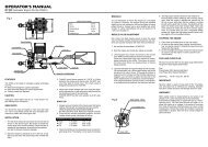
Electronics Installation and Wiring<br />
Servo<br />
(PIT)<br />
Battery<br />
Receiver<br />
3-6 LiPo Cells<br />
18A ESC<br />
(AIL)<br />
(ELE)<br />
ESC<br />
GYRO<br />
Gyro Gain Plug(S)<br />
(PIT)<br />
(RUD)<br />
Servo<br />
(ELE)<br />
ESC<br />
Tail Servo<br />
Heading Hold<br />
Gyro ( GU-210 )<br />
To Receiver<br />
ESC<br />
(AIL)<br />
(ELE)<br />
GYRO<br />
Gyro Gain Plug(S)<br />
(PIT)<br />
(RUD)<br />
Servo<br />
(AIL)<br />
Motor<br />
CCPM<br />
(Swash plate)<br />
Servo<br />
(PIT)<br />
( S ) Gyro<br />
Sensitivity<br />
CH-6<br />
CH-1<br />
6/B<br />
5<br />
4<br />
3<br />
2<br />
1<br />
Servo<br />
(ELE)<br />
Heading Hold<br />
Gyro ( GU-210 )<br />
Tail Servo<br />
plug into<br />
Gyro<br />
To Receiver CH4<br />
To Receiver CH5 or Ch7<br />
6ch<br />
Racng Team<br />
Micro Receiver (6CH)<br />
FUTABA HITEC JR Sanwa Blue ESC GYRO<br />
Bird<br />
Signal (S) White Orange Orange Blue Orange Orange White Yellow<br />
Positive (+) Red Red Red Red Red Red Red<br />
Negative (-) Black Black Brown Black Brown Brown Black<br />
FM
Tail servo and the heading hold gyro setup<br />
1. Install the Gyro and the tail servo.<br />
2. Connect the tail pushrod to the servo.<br />
Make sure the servo arm is 90 degrees<br />
to the tail pushrod. The ball link<br />
should be set at the second hole on<br />
the servo arm (as shown on left).<br />
3. Slide the servo mount and the tail<br />
servo along the tail boom until the<br />
tail pitch lever is parallel to the<br />
tail output shaft or slightly<br />
forward.<br />
4. Set the Gyro limit properly, make<br />
sure the tail pitch yoke do not touch<br />
the tail pitch lever mount and the<br />
tail rotor hub when the tail servo<br />
moves to the left and the right<br />
maximum travel volumn. If the Gyro<br />
you used do not have the function<br />
of Limit , set the function of ATV /<br />
End Point / Travel Adjust on<br />
transmitter to adjust the proper<br />
travel volumn of the tail servo.<br />
5. If the tail oscillates or wags at<br />
less than 60% gain,you will need to<br />
move the ball link to the hole which<br />
is closer to the serve Gyro<br />
limit properly. The ideal gain setting<br />
is around 70%.<br />
Important:<br />
Do not touch the<br />
tail pitch lever<br />
mount and the<br />
tail rotor hub.
Servo and Linkage Installation<br />
Rotate each blade clockwise until<br />
the blades are parellel to the flybar.<br />
(Top View)<br />
Servo and linkage setting<br />
1. Adjust the length of the control<br />
linkages as figure below. Make sure<br />
that the the servo arms for CCPM<br />
swashplate are all in the same length.<br />
Level<br />
2. The servos at neutral should have the<br />
servo arms at level position, and the<br />
arm should be 90 degrees to<br />
the control linkage. At this<br />
point,the swash<br />
plate and the<br />
scissor arms<br />
should be level,<br />
and the pitch<br />
should be set at<br />
0 degrees.<br />
Length of each linkage<br />
L1 L2<br />
Slide the swashplate up or down until<br />
the blades are parallel to the flybar (Left<br />
View). The collective pitch angle is zero<br />
at this position.<br />
Level<br />
L3<br />
L4 L5<br />
30.5 mm 31 mm 25.5 mm 37.7 mm 35.3mm<br />
L1<br />
L2<br />
L3<br />
L4<br />
L5
(maximum)<br />
+ 15 degrees<br />
0 degrees<br />
- 15 degrees<br />
(maximum)<br />
Distance S<br />
Pitch : +13<br />
(11.5mm)<br />
(swashplate height)<br />
Pitch Setting<br />
Pitch : 0<br />
(7mm)<br />
Head speed and pitch settings<br />
Pitch : -13<br />
(2.5mm)<br />
1. Total collective pitch range should be approx 30 degrees ( -15 ~ +15 ).<br />
Normal flight should be about +12 to -5 degrees.<br />
2. The re<strong>com</strong>mended hovering head speed should be at least 3000rpm.<br />
This can be checked with a tachometer. If the helicopter is unstable in<br />
a hover, reduce the pitch at this throttle setting to gain more head<br />
speed.If this does not solve the problem, increase the throttle curve.<br />
3. Refer to the next page for getting more informations about setting.<br />
4. The wooden blades or FRP blades are re<strong>com</strong>manded for 3D flight.<br />
Be sure to balance your blades before flying.
IMPORTANT:<br />
W1.4X2.5X0.4<br />
B1.5X4X1.3<br />
M1.4X4<br />
W2X3.5X0.5<br />
PW3X3.7X1.6<br />
O ring<br />
#203849<br />
M1.4X5<br />
W1.4X2.5X0.4<br />
B1.5X4X1.3<br />
B2X5X2.5<br />
M2X10<br />
Main Rotor Head Assembling - 1<br />
Make sure to use the non-locktite adhesive or similar material to<br />
adhere the screws while assemble the parts.<br />
#203625<br />
M1.4X5<br />
M1.4X6<br />
M2X8.4<br />
P1.5X7.7<br />
M2X2<br />
M1.4X6<br />
P1.2X13.5
M1.4X5<br />
Ø1.4X6<br />
IMPORTANT:<br />
Main Rotor Head Assembling - 2<br />
Make sure to use the non-locktite adhesive or similar material to<br />
adhere the screws while assemble the parts.<br />
③<br />
P1.4X2X3<br />
M1.4X6<br />
① ②<br />
B1.5X4X1.2<br />
W1.4X2.5X0.4<br />
B8X12X2.5<br />
#203591<br />
M1.4X5<br />
M1.4X15<br />
P1.4X2X9
IMPORTANT:<br />
#203121<br />
B2X5X2.3F<br />
P2X3.5X6.4<br />
P2X3X3.5<br />
B2X5X2.5<br />
M2X8.4<br />
Main Frame Assembling - 1<br />
Make sure to use the non-locktite adhesive or similar material to<br />
adhere the screws while assemble the parts.<br />
Fig.1<br />
M2X5<br />
Parts in Fig.1 are for<br />
belt version only<br />
B3X6X2<br />
M2X3.2<br />
P2X3.5X12<br />
Countsunk Washer<br />
(Use the locktite adhesive to adhere<br />
both bearings to bearing mounts.)<br />
M2X4.6<br />
Ø1.4X4<br />
#203125<br />
M2X3.2<br />
The length of tail boom<br />
which is inserted into<br />
the tail gear case are<br />
different between<br />
P2X3.5X9.5<br />
Belt Version and<br />
Shaft version<br />
(Belt version) (Shaft version)<br />
M2X8.4<br />
M1.4X5
IMPORTANT:<br />
M2X3.2<br />
M2X14<br />
P2X3.5X8.5<br />
M2X3.2<br />
3.5X3.5X31<br />
M1.4X6<br />
Main Frame Assembling - 2<br />
Make sure to use the non-locktite adhesive or similar material to<br />
adhere the screws while assemble the parts.<br />
B3X6X2<br />
#203636<br />
Ø1.4X3<br />
#203311<br />
P2X3.5X12<br />
#203209
Double Joints Tail Slider & CNC Tail Gear Case Assembling<br />
IMPORTANT:<br />
Make sure to use the non-locktite adhesive or similar material to adhere<br />
the screws while assemble the parts.<br />
Upper tail pitch lever<br />
The bearings and the<br />
tail pitch link should<br />
be adhered by the<br />
locktite adhesive.<br />
Vertical<br />
B1.5X3.4X2<br />
P2X2.5X4.6<br />
M1.4X3<br />
#203135<br />
N2X4<br />
M2X8<br />
M1.4X5<br />
M1.4X5<br />
W3X4.6X0.5<br />
P1.4X2.5X1.24<br />
P1.2X3.5<br />
M1.4X6<br />
B1.4X4X2<br />
B3X6X2<br />
M1.4X5<br />
P2X3X7.7
IMPORTANT:<br />
Distance B =<br />
Make sure to use the non-locktite adhesive or similar material to<br />
adhere the screws while assemble the parts.<br />
4.5mm<br />
Use Locktite 609 , 680 , or<br />
similar material to adhere<br />
the long neck pinion gear<br />
to the motor shaft.<br />
( Make sure the distance B<br />
is correct. )<br />
M3X3<br />
64T<br />
B3X7X2<br />
B3X6.5X6<br />
120T<br />
Belt Driven Unit Assembling-1<br />
15T<br />
Motor can be mounted front or rear<br />
M3X5<br />
#203232
IMPORTANT:<br />
Make sure to use the non-locktite adhesive or similar material to<br />
adhere the screws while assemble the parts.<br />
Distance B =<br />
4.5mm<br />
Use Locktite 609 , 680 , or<br />
similar material to adhere<br />
the long neck pinion gear<br />
to the motor shaft.<br />
( Make sure the distance B<br />
is correct. )<br />
Shaft Driven Unit Assembling-1<br />
120T<br />
B3X6.5X6<br />
B3X7X2<br />
M3X3<br />
15T<br />
9T<br />
#203232<br />
Adjust the motor front<br />
or rear to make sure<br />
the gear mesh was<br />
set properly.
IMPORTANT:<br />
Shaft Driven Unit Assembling-2<br />
Make sure to use the non-locktite adhesive or similar material to<br />
adhere the screws while assemble the parts.<br />
#203126<br />
P1.4X2.5X1.24<br />
M1.4X5<br />
M2X5<br />
W3X4.6X0.5<br />
B3X6X2.5<br />
Ø1.4X4<br />
Ø1.4X4<br />
Insert the tail shaft assembly into the boom holder, install the crown gear onto the<br />
driven shaft , adjust the gear mesh and tighten the screws of the boom holder.<br />
(Lower pinion 9T for crown gear)<br />
The lower pinion must not touch<br />
the main gear.<br />
Countsunk Washer<br />
(Upper pinion 15T for main gear)
Product Functions<br />
Battery Management<br />
There is a built-in Battery Management function in the speed controller. The power cut off timing is based on the cell number<br />
and continuous current drains of the battery. There are two options defined in the battery management, one is for Li-Polymer<br />
batteries and another for using with NiMH battery. The battery management allows you to protect your batteries from over<br />
discharge and moreover to extend the lifetime of your batteries.<br />
Flying Mode<br />
The flying mode function offers you four options for different aircrafts. You could choose from Airplane, Glider, Helicopter<br />
without governor and Helicopter with governor.<br />
Set Up Procedure<br />
1. To enter set up mode and throttle calibration<br />
Due to the signal differentiation amount different remote control brands, it is strongly re<strong>com</strong>mended to run the throttle curve<br />
initiation process whenever set up a new aircraft.<br />
I. Shifting the throttle position to the full throttle/full speed.<br />
II. Power on the transmitter<br />
III. Power on the speed controller, the motor will <strong>com</strong>e up with acknowledge tones ♪-♪-♪-♪-♪-♪<br />
IV. Moving the throttle position to the minimum/stop position, the motor will <strong>com</strong>e up with acknowledge tones ♪-♪-♪-♪<br />
The speed controller recognized the exactly throttle range then optimizes the throttle curve after this progress. When finish the<br />
calibrating process, you could simply shutdown the power to leave the other settings unchanged. If not, simply waiting for 1<br />
second. The speed controller will enter the set up mode.<br />
2.Battery Management<br />
The first section of setup is battery management. This section offers 2 options for using with either NiMH or Li-Polymer battery.<br />
The motor will <strong>com</strong>e up the corresponding tones as indicator. The following is the indication with graphic reference.<br />
o Standard discharge protection for Li-Polymer (Factory Default) ♪-♪<br />
o +5V cut-off protection for Ni-MH ♪-♪♪<br />
When intending to choose one of above options, simply push throttle stick from minimum/stop to maximum/full throttle after<br />
the indication tone, then pull throttle stick back to the minimum/stop position to confirm after the acknowledge tone. You could<br />
simply shut down the power if you don t need any further settings. If you want to skip this section and leave current setting<br />
unchanged, just keep throttle stick in minimum position and wait the speed controller to enter next section.<br />
3.F lying Mode<br />
The following section is flying mode setting. This section offers 4 options. They are Airplane, Glider and Helicopter without<br />
Governor/with Governor. The motor will <strong>com</strong>e up the corresponding tones as indicator. The following is the indication with<br />
graphic reference.<br />
o Aircraft ♪♪-♪<br />
o Glider ♪♪-♪♪<br />
o Helicopter with Governor ♪♪-♪♪♪<br />
o Helicopter without Governor (Factory Default) ♪♪-♪♪♪♪<br />
ESC instruction<br />
When intending to choose one of above options, simply push throttle stick from minimum/stop to maximum/full throttle after the<br />
indication tone, then pull throttle stick back to the minimum/stop position to confirm after the acknowledge tone. Shutdown the<br />
power, and now the speed controller is ready to fly.<br />
More about Battery Management System<br />
This section gives you more details of the smart design of battery management in order to help you to utilize the function.<br />
Technically the power cut off timing was based on the cell number and continuous current drains of the battery. The speed<br />
controller will calculate the timing and cut the power off with two steps. Because the last stage of each battery discharge cycle<br />
ha s quick voltage drop, such function will provide a safe process during the operation.<br />
1st step: enabled when the single cell reaches the low point, the motor will be forced to lower the RPM by microprocessor<br />
2nd step: enabled when the single cell reaches the lowest point defined in the system, the motor will be <strong>com</strong>pletely cut off.<br />
To regain the power, the user needs to adjust the throttle stick to the stop position until the battery voltage <strong>com</strong>es back to the<br />
safe level.<br />
The following are the detailed definition of each option in battery management.<br />
o NiMH battery<br />
+5.0 volt cut off<br />
o Li-Polymer standard discharge (Factory Default)<br />
1st step voltage @ 2.9V<br />
2nd step voltage @2.6V<br />
Caution!!<br />
High power motor systems could be very dangerous. High current could generate heat on wires, batteries, and motors. Always<br />
follow the instruction and use proper tools to set up the system within safe range. Always fly at a designed field with caution<br />
even though this controller is equipped with safety arming program.
Specifications of Motor and ESC<br />
Specifications of 18A ESC<br />
Working Voltages(Maximum) ------------------------------ 5.5 V ~ 16.8 V(Maximum)<br />
Maximum Current(Instantaneous) -------------------------------------------------- 24 A<br />
Continual Current ------------------------------------------------------------------------ 18 A<br />
Built-in BEC ------------------------------------------------------- Maximum Input 12.6 V<br />
Output 5 V / 2 A<br />
Low Battery Protect ------------------------------------------------------ 3.1V~2.9V / cell<br />
Temperature Overload --------------------------------------------------------------- 120 ℃<br />
Specifications of BL Motor<br />
KV value ----------------------------------------------------------------------------------- 4800<br />
Maximum Current(Instantaneous) ------------------------------------------------- 15 A<br />
Efficiency ---------------------------------------------------------------------------------- 85%<br />
Voltage Range -------------------------------------------------------------------- 7 V ~ 15 V<br />
Motor Weight ---------------------------------------------------------------------------- 28 g<br />
Motor Diameter ------------------------------------------------------------------- 24.5 mm<br />
Motor Length ------------------------------------------------------------------------ 24 mm<br />
Motor Output Shaft Diameter ----------------------------------------- 2.3x12 (L) mm<br />
Bearings ------------------------------------------------ (3x6mm)*1 pc , (3x7mm)*1 pc<br />
Poles -------------------------------------------------------------------------------------------- 8
GU-365 FES Gyro installing<br />
1.Cut the sponge tape into 4 small squares (8mm), attached them to the<br />
corners of name plate side.<br />
Gyro must not be tied<br />
2.Attach the GU-365 Gyro to heli<br />
as shown in figure above.<br />
Battery<br />
Use the magic<br />
tape to attach<br />
the battery onto<br />
battery plate<br />
(bottom side),<br />
and it is re<strong>com</strong>mended<br />
to tie them together by<br />
Rubber Band or Touch<br />
Fastener Cable Tie.<br />
(AIL)Servo<br />
(PIT)Servo<br />
Receiver<br />
Wires must not<br />
be pulled tightly<br />
Gyro box must not have contact with<br />
heli except sponge tape<br />
3.The trimmers and switches of GU-365 Gyro<br />
should be aligned with the slots.<br />
CA<br />
(ELE)Servo<br />
18A ESC<br />
GU-365 FES Gyro<br />
Use C/A to adhere<br />
frames and bottom<br />
plate which may<br />
avoid vibration<br />
IMPORTANT: Please refer to the instruction manual of GU-365 gyro<br />
for more setting information.
M1.4X6<br />
M2X3<br />
Parallel<br />
(Fig.4)<br />
M2X12<br />
FES 2Blade Head & Swashplate Assembling<br />
B2X5X2.5<br />
M2X8.4<br />
P2X3.5X2.5<br />
M1.4X6<br />
W1.4X2.5X0.4<br />
P1.4X2X3.1<br />
Ø1.4X6<br />
M1.4X5<br />
B1.5X4X1.2<br />
Grips and Head Assembling Mast and Upper Swashplate Lock Assembling<br />
Install the linkages<br />
0 Pitch degrees (Fig. 1)<br />
The ball link and the arm<br />
shod e perpendicular<br />
at 0 pitch degrees (Fig.2)<br />
Equal<br />
IMPORTANT:<br />
The socket set screws of the Swashplate Lock should be tightened<br />
after 3 conditions are all set properly:<br />
1. The main blade is at 0 pitch degrees.(Fig.1)<br />
2. The arm and the ball link of the Upper Swashplate Lock are perpendicular.(Fig.2)<br />
3. The position of upper swashplate, lower swashplate and the main grips was set as (Fig.3).<br />
4. The arm of the Upper Swashplate Lock and the Main Grips are parallel from top view.(Fig.4)<br />
The position of upper swashplate, lower<br />
swashplate and the main grips.(Fig.3)<br />
Top View Assembled
203308<br />
SP Main Rotor Blades(200L)<br />
203702<br />
FES Upper Swashplate Lock Ass'y<br />
(for 100~250 class 3mm Mast)<br />
203306<br />
203620 203625<br />
203851<br />
203560 203570 203580<br />
203700<br />
203701<br />
203704<br />
203705 203706 203708<br />
203711 203712 203715 203716<br />
203691<br />
Optional & Replacement Parts<br />
CNC Main Grips set<br />
(for 100~200 class)<br />
CNC See-Saw Set CNC See-Saw Spindle<br />
Main Rotor Yoke<br />
with Stop Plate<br />
FES 4Blade Rotor Head<br />
(for 100~250 class 3mm Mast)<br />
FES 2Blade Head and Swashplate<br />
Ass'y (for 100~250 class 3mm Mast)<br />
Main Rotor Blades Pack<br />
(Wooden 200L)<br />
FES 2Blade Rotor Head<br />
(for 100~250 class 3mm Mast)<br />
FES 4Blade Swashplate Ass'y<br />
(for 100~250 class 3mm Mast)<br />
FES 3Blade Head and Swashplate<br />
Ass'y (for 100~250 class 3mm Mast)<br />
861902 203591<br />
Tail Rotor Belt<br />
(for H200 Series)<br />
CNC Swashplate Assembly CNC Mixing Arms<br />
FES 3Blade Swashplate Ass'y<br />
(for 100~250 class 3mm Mast)<br />
FES 2Blade Rotor Head & Upper<br />
Swashplate Lock (for 100~250 class<br />
3mm Mast)<br />
FES 5Blade Rotor Head<br />
(for 100~250 class 3mm Mast)<br />
CNC Stop Plate<br />
(for 100~400 class)<br />
FES 3Blade Rotor Head<br />
(for 100~250 class 3mm Mast)<br />
FES 5Blade Swashplate Ass'y<br />
(for 100~250 class 3mm Mast)<br />
203692 203693<br />
FES 4Blade Head and Swashplate<br />
Ass'y (for 100~250 class 3mm Mast)<br />
CNC Washout Base & Arms<br />
Assembly<br />
FES 5Blade Head and Swashplate<br />
Ass'y (for 100~250 class 3mm Mast)
203707 203710<br />
203714 203718<br />
FES 2Blade System full conversion set<br />
(for 100~250 class 3mm Mast)<br />
203085 203115<br />
High Performance Tail Rotor<br />
Blades Pack<br />
203128<br />
203125<br />
901503<br />
203211<br />
203326 203327 203328<br />
203241<br />
203121<br />
203544<br />
Optional & Replacement Parts<br />
H200 Linkage Set<br />
203126<br />
203325<br />
H200 Metal Parts Pack<br />
Universal Links Pack(3.5mm) Tail Pitch Link Set Double Link set<br />
Flybar Adaptors Pack<br />
High Performance Tail Output<br />
Shaft Set(for belt version)<br />
H200SD Pinion Gear(15T x 10T)<br />
High Performance Auto-rotation<br />
Main Gear Set(without bearings)<br />
FES 3Blade System full conversion set<br />
(for 100~250 class 3mm Mast)<br />
High Performance Stabilizer<br />
Blades Pack<br />
H200SD Tail Output Shaft Set<br />
Pinion Gear 15T-100(2.3x5mm)<br />
203127<br />
203542 203543<br />
203230 203232 203233<br />
Mast Collars Pack(S)<br />
FES 4Blade System full conversion set<br />
(for 100~250 class 3mm Mast)<br />
H200SD Crown Gear<br />
One Way Bearing & Auto-rotation<br />
Main Gear Set<br />
Main Pulley Collars(for High<br />
Performance Main Gear)<br />
FES 5Blade System full conversion set<br />
(for 100~250 class 3mm Mast)<br />
H200SD Pinion Gear(15T x 9T)<br />
One Way High Performance Main<br />
Gear Set(for Shaft Version)<br />
Upper Mast Collar
203151<br />
Guide Wheel with Bearing Pack<br />
803725<br />
Flange Bearing(3x6x2.5)<br />
203571<br />
203250 203270<br />
203271<br />
203280<br />
203290<br />
203261 203450<br />
203183<br />
203847<br />
203329<br />
203849<br />
203445<br />
203446 203608 203616 203634<br />
203635 203636<br />
Landing Gear Skids Pack<br />
(Titanium anodized)<br />
Ball & Extension for<br />
CNC Swashplate<br />
Optional & Replacement Parts<br />
Bearings(1.4x4x1.2)x2pcs Bearings(1.4x4x2)x2pcs Flange Bearing(2x5x2.3)x2pcs<br />
Bearings(2x5x2.5)x3pcs<br />
H200V2 Lower Frame Set CF Fin & Tail(D Type)-Silver<br />
CNC Integrated Middle Mount CNC Motor Mount<br />
H200 Body Retainers Pack<br />
O Ring and Paper washer for<br />
H200 Main Rotor Spindle<br />
Bearings(3x6x2.5)x2pcs<br />
H200V2 Lower Frame Conver<br />
-sion Set (V1 convert to V2)<br />
Swashplate Guide<br />
High Rigidity Landing<br />
Gear Brace Set<br />
Spindle shafts Pack for<br />
H200 Main Rotor Yoke<br />
H200V2 Upper Frame Set<br />
(for 6g~9g Servo)<br />
CNC Mast Mount<br />
203565<br />
CNC Swashplate Guide<br />
203680<br />
CF Landing Gear Brace & Skid<br />
203135<br />
Tail Hubs Pack
203191 203196<br />
Titanium anodized Tail Booms<br />
Pack (for Belt version)<br />
203222<br />
Long Main Shafts Pack<br />
203582<br />
203583<br />
203197<br />
203240<br />
203598 203630<br />
203632<br />
203675<br />
Optional & Replacement Parts<br />
203223<br />
CNC Tail Pitch Lever Set CNC Rudder Control Guide<br />
CNC Double Joints Tail Slider Set<br />
(with double bearings)<br />
CNC Alu Tail Gear Case with Double<br />
Joints Tail Slider(for Belt version)<br />
832010<br />
842014 203662 203663<br />
Socket Head Cap Screw(M2x14)x10pcs<br />
(for 100~250 class FES 4~5Blade Rotor Head)<br />
Black CF Tail Boom<br />
(for Belt version)<br />
H200 Alu Tail Driven Shaft<br />
with Bevel Gear<br />
CNC Tail Rotor Grip Set(with Hub)<br />
Machine Screws<br />
(M2x10)x10pcs<br />
Countsunk Washer & Screw<br />
set (M2x3.2)x10<br />
Titanium anodized Tail Boom<br />
with one bearing(Shaft version)<br />
Flybars Pack<br />
203209<br />
203532<br />
203584 203596<br />
CNC Tail Support Clamp<br />
CNC Universal Battery Plate<br />
H200 Tail Boom Support Set<br />
(Long)<br />
H200 Rudder Linkage with<br />
Rudder Control Guide<br />
CNC Tail Pitch Link Set<br />
203665<br />
842010 842012<br />
Socket Head Cap Screw(M2x14)x10pcs<br />
(for 100~250 class FES 2Blade Rotor )<br />
Countsunk Washer & Screw<br />
set (M1.4x4)x10<br />
CNC Alu Tail Gear Case with Double<br />
Joints Tail Slider(for Shaft version)<br />
Socket Head Cap Screw(M2x12)x10pcs<br />
(for 100~250 class FES 3Blade Rotor Head)<br />
883503<br />
Metal Balls with Stand<br />
(3.5mm) x 10
203311<br />
Damper Rubbers Pack<br />
(for canopy)<br />
204904<br />
Decal(2)<br />
203165<br />
H200 FRP Painted Canopy<br />
(A Type)<br />
203172<br />
H200 FRP Painted Canopy<br />
(Green)<br />
Optional & Replacement Parts<br />
203529<br />
Tail Servo Mount Set<br />
910011<br />
Blade Support<br />
(for H100~H200)<br />
203920 203930<br />
203531<br />
203166<br />
203572<br />
203167<br />
203169 203170 203171<br />
H200 FRP Painted Canopy<br />
(Red)<br />
203173<br />
H200 FRP Painted Canopy<br />
(Purple)<br />
Hurricane 200V2 SE Hurricane 200V2 FES<br />
Boom Support Pack<br />
Light-weight Body-Canopy(9g)<br />
H200 FRP Painted Canopy<br />
(Orange)<br />
203174<br />
H200 FRP Painted Canopy<br />
(Yellow)<br />
Mini Spacer & Brass Washer<br />
Spare Pack<br />
H200 FRP Painted Canopy<br />
(B Type)<br />
H200 FRP Painted Canopy<br />
(Blue)<br />
203613<br />
H200V2 Frames Set
921601 921602 921603 922601<br />
Micro Receiver<br />
Micro Receiver<br />
Micro Receiver<br />
(SRX-6UH-40MHZ) (SRX-6UH-72MHZ)<br />
(SRX-6UH-35MHZ)<br />
BMS 306BB Servo<br />
923182<br />
(GUEC GE-182)ESC 18A<br />
with Connectors(For BL Motor)<br />
926081<br />
(GUEC GB-081)Li-Po Battery<br />
(11.1v 800mah)<br />
851812<br />
BL Motor 200w/4800kv<br />
with Connector<br />
924210 924365<br />
926080<br />
(GUEC GU-210)<br />
Heading Hold Gyro<br />
203503<br />
BL Motor 200w/4800kv with 15T<br />
Gear/Connector(for belt version)<br />
(GUEC GU-365) Flybarless<br />
E-Stabilizer (FES)<br />
(GUEC GB-080)Li-Po Battery<br />
(7.4v 800mah)<br />
203505 203506<br />
BL Motor 200w/4800kv with 9/15T<br />
Gear/Connector(for shaft version)<br />
BL Motor 200w/480kv with 10/15T<br />
Gear/Connector(for shaft version)
Specification of Screws ( 1 : 1 )<br />
M1.4<br />
Machine screws<br />
Ø1.4<br />
Self taping screws<br />
Ø2.0<br />
Self taping screws<br />
M2.0<br />
Tiny head machine screws<br />
M2.0<br />
Machine screw<br />
M2.0<br />
Socket head machine screws<br />
M2.0<br />
Socket set screws<br />
Linkage rods<br />
Ø2<br />
15.0<br />
8.0<br />
12.0<br />
8.4<br />
10.0<br />
14.0<br />
2.0<br />
12.0<br />
16.0<br />
Ø3<br />
22.0<br />
7.0<br />
6.0<br />
10.0<br />
4.6<br />
12.0<br />
3.0<br />
6.0<br />
5.0<br />
8.0<br />
3.2<br />
10.0<br />
5.0<br />
4.0<br />
8.0<br />
4.0<br />
3.0<br />
5.0<br />
3.0<br />
3.0
200 V2


![Spartan Quark Gyro Installation Guide [Doc. v1.0] - Spartan RC](https://img.yumpu.com/53147979/1/190x196/spartan-quark-gyro-installation-guide-doc-v10-spartan-rc.jpg?quality=85)