

Power Jack - Atwood Mobile Products
Power Jack - Atwood Mobile Products
Power Jack - Atwood Mobile Products

You also want an ePaper? Increase the reach of your titles
YUMPU automatically turns print PDFs into web optimized ePapers that Google loves.
SAFETY ALERT SYMBOLS<br />
Safety Symbols alerting you to potential personal safety hazards. Obey all safety<br />
messages following these symbols.<br />
� WARNING � CAUTION<br />
avoid possible avoid possible<br />
injury or death injury and/or property damage<br />
FOR YOUR SAFETY READ ALL INSTRUCTIONS<br />
BEFORE INSTALLATION AND OPERATION<br />
Installer: Provide these instructions to the consumer.<br />
Consumer: Keep documents for future reference.<br />
The <strong>Atwood</strong> <strong>Power</strong> <strong>Jack</strong> is a 12-volt DC motor driven screw jack<br />
intended for use on recreational type and marine trailers. Patent #<br />
D349800. <strong>Jack</strong> is used to level trailer or raise and lower coupler for<br />
hookup to tow vehicle.<br />
� CAUTION<br />
PERSONAL INJURY/PROPERTY DAMAGE<br />
• Retract jack fully before towing.<br />
• Do not use blocks to increase height of jack.<br />
• Use 3500 lb. Heavy Duty <strong>Power</strong> <strong>Jack</strong> if you use equalizer bars<br />
between the trailer and the tow vehicle.<br />
LIGHT WT STANDARD DELUXE HEAVY DUTY MARINE<br />
SHORT<br />
Max. Lifting Cap. LBS 1500 2500 2500 3500 1000<br />
INSTALLATION<br />
1. Block tires of trailer and securely support trailer tongue.<br />
2. The <strong>Atwood</strong> RV <strong>Power</strong> <strong>Jack</strong> is designed to attach to the top<br />
surface of an A-frame type tongue having mounting holes typical<br />
of the <strong>Atwood</strong> A-frame couplers FIG 1. Use coupler installation<br />
instructions (MPD 87984) if installing coupler. The Marine <strong>Power</strong><br />
<strong>Jack</strong> attaches to the side of a straight tongue trailer.<br />
3. A lower support plate must be used for side support of the RV<br />
jack on the lower surface of the A-frame FIG 1.<br />
HOLE DIAMETERS: Light Weight 2.02˝ (MIN) 2.09˝ (MAX)<br />
Standard / Short / Deluxe / Heavy Duty 2.20˝ 2.28˝<br />
Hole in lower support plate must align with hole in coupler.<br />
TO ORDER LOWER SUPPORT PLATE: Light Weight - <strong>Atwood</strong> MPD 80263<br />
Standard / Short / Deluxe / Heavy Duty - <strong>Atwood</strong> MPD 80570<br />
Using 1/8˝ fillet weld, No. E6011 AWS welding rod 1/8˝ diameter,<br />
machine amps (AC or DCRP) at 160-180 with 50 volts, weld<br />
plate full length on each side to underside of A-frame. The<br />
maximum frame height is 6 inches.<br />
4. Place RV jack through holes in coupler and lower support plate,<br />
FIG 1-A. Attach with three (3) bolts (3/8˝ dia. x 5/8˝ long, grade 5,<br />
(provided) FIG 1-B. NOTE: Torque bolts to 15 foot lbs. minimum<br />
/20 foot lbs. max.<br />
Note: There must be metal to metal contact between jack and coupler.<br />
The three mounting bolts with attached star washers must be used.<br />
The star washers are designed to remove paint on the surface of<br />
jack flange. The bolts also should remove paint from the mounting<br />
holes in coupler. If there is a grounding problem (i.e. no power) check<br />
these two surfaces to be sure there is metal to metal contact between<br />
jack and coupler. For wiring, see WIRING ILLUSTRATIONS FIG 2 & 3.<br />
9<br />
1<br />
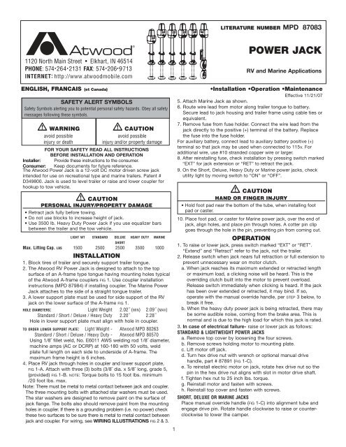
LITERATURE NUMBER MPD 87083<br />
POWER JACK<br />
RV and Marine Applications<br />
ENGLISH, FRANCAIS (et Canada) •Installation •Operation •Maintenance<br />
Effective 11/21/07<br />
5. Attach Marine <strong>Jack</strong> as shown.<br />
6. Route wire lead from motor along trailer tongue to battery.<br />
Secure lead to jack housing and trailer frame using cable ties or<br />
equivalent.<br />
7. Remove fuse from fuse holder. Connect the wire lead from the<br />
jack directly to the positive (+) terminal of the battery. Replace<br />
the fuse into the fuse holder.<br />
For auxiliary battery, connect lead to auxiliary battery positive (+)<br />
terminal so that jack may be used when connected to 115v. For<br />
additional wire, use #10 stranded copper wire or larger.<br />
8. After reinstalling fuse, check installation by pressing switch marked<br />
“EXT” for jack extension or “RET” to retract the jack.<br />
9. On the Short, Deluxe, Heavy Duty or Marine power jacks, check<br />
utility light by moving switch to “ON” or “OFF”.<br />
� CAUTION<br />
HAND OR FINGER INJURY<br />
• Hold foot pad near the bottom of the tube, when installing foot<br />
pad or caster.<br />
10. Place foot pad, or caster for Marine power jack, over the end of<br />
jack, align holes, and place pin through holes. A cotter pin clip<br />
goes through the hole in the pin, preventing pin from coming out.<br />
OPERATION<br />
1. To raise or lower jack, press switch marked “EXT” or “RET”.<br />
“Extend” and “Retract” refer to the jack, not the trailer.<br />
2. Release switch when jack nears full retraction or full extension to<br />
prevent unnecessary wear on motor clutch.<br />
a. When jack reaches its maximum extended or retracted length<br />
or maximum load, a clicking noise will be heard. This is the<br />
overriding clutch built into the motor to prevent overload.<br />
Release switch immediately when clicking is heard. If the jack<br />
has been over extended or retracted, it may bind. If so,<br />
operate with the manual override handle, per STEP 3 below, to<br />
break it free.<br />
b. When the heavy duty power jack is being retracted, there may<br />
be some audible noise, coming from the brake area. This is<br />
normal and is due to the high load for which this jack is rated.<br />
3. In case of electrical failure- raise or lower jack as follows:<br />
STANDARD & LIGHTWEIGHT POWER JACKS<br />
a. Remove top cover by loosening the four screws.<br />
b. Remove screws holding motor to mounting plate.<br />
c. Lift motor off jack.<br />
d. Turn hex drive nut with wrench or optional manual drive<br />
handle, part # 87891 (FIG 1-C).<br />
e. To reinstall electric motor on jack, rotate hex drive nut so the<br />
pin in the hex drive nut aligns with slot in motor drive shaft.<br />
f. Tighten hex nut to 25 inch lbs. torque.<br />
g. Reinstall motor and fasten with screws.<br />
h. Reinstall top cover and fasten with screws.<br />
SHORT, DELUXE OR MARINE JACKS<br />
Place manual override handle (FIG 1-C) into alignment tube and<br />
engage drive pin. Rotate handle clockwise to raise or counterclockwise<br />
to lower the camper.
HEAVY DUTY POWER JACKS<br />
Place manual override handle (FIG 1-C) into alignment tube and<br />
engage drive pin. Rotate handle counterclockwise to raise or<br />
clockwise to lower the camper.<br />
MAINTENANCE<br />
1. Before each use, inspect jack tubes and replace if bent or damaged.<br />
2. If wiring is connected to battery terminal, inspect at least twice each<br />
year for corrosion. Clean with a solution of baking soda and water,<br />
then apply a thin coat of grease. NOTE: The motor ground screw<br />
(FIG 1-D) and mounting bolts (FIG 1-B) must be cleaned too if a ground<br />
continuity problem occurs.<br />
Guides are only intended for use on <strong>Atwood</strong> ® products by service<br />
technicians who have successfully completed <strong>Atwood</strong> ® training.<br />
This guide should be used in conjunction with the appropriate<br />
Instruction Manual provided with the product and any applicable<br />
Industry Standards. This is not intended to be a complete list.<br />
Please direct questions concerning service of <strong>Atwood</strong> ® products to<br />
866-869-3118 before proceeding.<br />
� WARNING<br />
PERSONAL INJURY AND/OR PRODUCT DAMAGE<br />
• If any of the following conditions develop, the trailer must not be<br />
used until proper corrective action is taken.<br />
CONDITION WITH SOLUTIONS<br />
MOTOR WILL NOT OPERATE<br />
No or low voltage..........................Check battery & electrical connections.<br />
Must have minimum of 10 VDC<br />
<strong>Jack</strong> flange not making good ......Clean paint or dirt from coupler frame<br />
contact to provide adequate<br />
ground with coupler surface<br />
Blown fuse ....................................Replace with 30 amp AWG fuse<br />
Loose wires on ON/OFF switch ....Secure wire connections<br />
ON/OFF switch faulty ....................Replace switch<br />
Motor faulty ..................................Replace motor<br />
POOR GROUND<br />
WHEN BUTTON IS PRESSED ON JACK -<br />
<strong>Jack</strong> doesn’t operate ....................Inspect motor mounting bolt for Loctite ® .<br />
<strong>Jack</strong> operates only partially up<br />
or down, or<br />
<strong>Jack</strong> runs intermittently<br />
9<br />
If Loctite ® found, replace with new 1/4-20<br />
x 3” screw and two lock washers. If bolt<br />
unavailable, clean present bolt and hole<br />
with wire buffing wheel. Inspect bolt<br />
2<br />
3. Once each year, extend jack as far as possible and clean inner ram<br />
tube. Coat tube with light coat of silicone spray lubricant.<br />
The Electric Drive Motor Landing Leg system is protected by a 30 amp<br />
fuse. If replacement is necessary, replace only with a Buss Type AGC-30<br />
fuse or equivalent, available in automotive supply stores.<br />
<strong>Power</strong> <strong>Jack</strong><br />
TROUBLE SHOOTING GUIDE<br />
Effective: 11/21/07<br />
hole. If dirty, clean with a 1/4-20 tap.<br />
MOTOR CLUTCH ENGAGES<br />
Normal if jack leg is at fully ..........None, but let go of switch when you hear<br />
retracted or extended position the clutch<br />
Worn worm gear ..........................Replace jack ram<br />
Dirty inner ram tube......................Clean ram tube and coat with light coat<br />
of silicone spray<br />
Bent inner ram ..............................Replace inner ram<br />
Clutch faulty ..................................Replace motor<br />
<strong>Jack</strong> at angle ................................Secure mounting bolts and ensure a<br />
support plate is used.<br />
Excessive tongue weights ............Determine if jack is adequate for tongue<br />
weight.<br />
UTILITY LIGHT DOES NOT WORK<br />
Loose wires on the ON/OFF ..........Secure wire connection<br />
switch<br />
Bad light bulb................................Replace bulb<br />
AMP DRAW<br />
Range of motor ............................8-45 amps<br />
IMPORTANT CAUTION - If equalizer bars are attached to the tow<br />
vehicle and the trailer while operating the power tongue jack,<br />
you may experience the motor clutching the moment the jack<br />
sees load. This will occur because you are lifting both the tongue<br />
of the trailer and the rear of the tow vehicle. The 1500 lb. and<br />
2500 lb. acme screw jacks cannot lift this excessive weight. To<br />
overcome this excessive weight, you should upgrade to the 3500<br />
lb. power jack. The ball screw mechanism utilized in this jack<br />
should allow you to lift this load.
REPLACEMENT SERVICE PARTS / PIÉCES DÉTACHÉES<br />
ITEM LIGHT WT STANDARD SHORT DELUXE HEAVY DUTY MARINE DESCRIPTION<br />
ARTICLE LÉGER STANDARD NORMAL DE LUXE LOURD MARIN DESCRIPTION<br />
1 87571 87571 87595 87595 87595 87595<br />
Upper Cover<br />
Couvercle supérieur<br />
2 87060 87060 87057 87057 87057 87057<br />
Cover Screw<br />
Vis du couvercle<br />
3 87055 87055 87942 87942 87942 87942 Motor Ground Screw / Vis<br />
4 86111 86111 86111 86111 86111 86111<br />
Lock Washer<br />
Rondelle de blocage<br />
5 75367 75367 75625 75625 75625 75625<br />
Motor and Terminals<br />
Moteur et bornes<br />
6 N/A N/A 87916 87916 87916 87916<br />
Cover Tube<br />
Tube du couvercle<br />
7 N/A N/A 87108 87108 87108 87108<br />
Bevel Gear Kit<br />
Pignon conique<br />
Gear Housing Cover<br />
8 N/A N/A 88002 88002 88002 88002 Couvercle de la boîte de vitesse<br />
9 N/A N/A 70298 70298 71132 70298<br />
Drive Pin<br />
Goupille d’entraînement<br />
10 N/A N/A 87941 87941 87941 87941<br />
Drive Shaft<br />
Arbre d’entraînement<br />
11 87573 87573 87597 87597 87597 87597<br />
Lower Cover<br />
Couvercle inférieur<br />
12 N/A N/A 87585 87585 87585 87585<br />
Wire & Light Bulb*<br />
Ampoule électrique*<br />
13 N/A N/A 87591 87591 87591 87591 Lens / Lentille<br />
14 87035 87035 87035 87035 87035 87035<br />
Hole Plug<br />
Bouchon de l’orifice<br />
15 80237 80512 87489 87500 87559 N/A<br />
<strong>Jack</strong> Hsing & Ram Asy 16˝ trvl<br />
Enveloppe du vérin et corps du cric à<br />
course de 16 po<br />
16 N/A N/A 87847 87847 87847 87847<br />
Washer Support<br />
Support de rondelle<br />
17 70229 70229 70667 70667 70667 70667 Pin / Tige<br />
18 87568 87568 87598 87598 87598 87598<br />
Ground Wire<br />
Fil de terre<br />
19 N/A N/A 87586 87586 87586 87586<br />
Light Switch<br />
Commutateur d’éclairage<br />
20 87570 87570 87570 87570 87570 87570<br />
Motor Switch<br />
Commutateur du moteur<br />
21 87327 87327 87327 87327 87327 87327<br />
Strain Relief Bushing<br />
Bague de bride de cordon<br />
22 N/A N/A 87599 87599 87599 87599<br />
Jumper Wire & Fuse<br />
Fil de connexion et fusible<br />
23 N/A N/A N/A N/A N/A N/A Fuse ▲ / Fusibles ▲<br />
24 87176 87176 87176 87176 87176 87176 Mounting Bolt / Boulon<br />
Manual Drive Handle<br />
25 OPTIONAL OPTIONAL 87891 87891 87891 87891 Manette de commande manuelle<br />
26 70269 70269 70269 70269 N/A 70269<br />
Cotter Pin<br />
Goupille fendue<br />
27 80238 87021 87021 87021 87021 --<br />
Round Foot Pad<br />
Coupelle ronde<br />
28 87709 87709 87709 87709 70215 87709<br />
Clevis Pin<br />
Axe de chape<br />
Hex Drive Nut<br />
29 87077 87077 N/A N/A NA N/A Écrou de commande hexagonal<br />
30 87569 87569 N/A N/A N/A N/A<br />
Fuse Wire<br />
Fil du fusible<br />
31 87150 Bracket / Patte<br />
32 84037 Caster / Roue pivotante<br />
*912 type T5 12 candle power *912 type T5 12 candelas<br />
▲ Buss Type AGC-30 amp fuse ▲ Buss type AGC-30 à fusible<br />
Marine<br />
<strong>Power</strong> <strong>Jack</strong><br />
3<br />
32<br />
31<br />
Standard &<br />
Lightweight<br />
<strong>Power</strong> <strong>Jack</strong><br />
5<br />
29<br />
11<br />
15<br />
Short, Deluxe,<br />
Heavy Duty &<br />
Marine<br />
<strong>Power</strong> <strong>Jack</strong><br />
4<br />
5<br />
7<br />
8<br />
9<br />
10<br />
11<br />
13<br />
14<br />
15<br />
6<br />
26<br />
27<br />
26<br />
27<br />
19<br />
12<br />
Cric électrique<br />
service normal<br />
et léger<br />
24<br />
17<br />
22<br />
28<br />
28<br />
1<br />
18<br />
17<br />
20<br />
30<br />
Cric électrique<br />
service court,<br />
deluxe et lourd<br />
1<br />
2<br />
3<br />
16<br />
18<br />
20<br />
21<br />
23<br />
25
1<br />
1<br />
C<br />
Attachment<br />
Hardware<br />
(included)<br />
D<br />
B<br />
A<br />
Boulonnerie de<br />
fixation (incluse)<br />
POWER JACK WIRING ILLUSTRATIONS<br />
Lightweight & Standard Short, Deluxe & Heavy Duty<br />
2<br />
RED LEAD<br />
FROM MOTOR<br />
BLACK<br />
FUSE WIRE<br />
FIL CONDUCTEUR<br />
ROUGE DU MOTEUR<br />
FIL NOIR<br />
DU FUSIBLE<br />
YELLOW LEAD<br />
FROM MOTOR<br />
FIL CONDUCTEUR<br />
JAUNE DU MOTEUR<br />
GROUND<br />
TO MOTOR<br />
SCREW<br />
FIL DE TERRE<br />
À LA VIS DU<br />
MOTEUR<br />
(DELUXE) - RED LEAD<br />
(HEAVY DUTY) - YELLOW LEAD<br />
FROM MOTOR<br />
3<br />
BLACK<br />
GROUND<br />
WIRE<br />
W/BLACK<br />
JUMPER<br />
BLACK FUSE<br />
WIRE W/RED<br />
JUMPER<br />
(DELUXE) - YELLOW LEAD<br />
(HEAVY DUTY) - RED LEAD<br />
FROM MOTOR<br />
RED<br />
JUMPER<br />
FROM<br />
FUSE WIRE<br />
BLACK<br />
WIRE FROM<br />
LAMP BASE<br />
SPADE CONNECTOR<br />
BLACK JUMPER<br />
FROM GROUND WIRE<br />
GROUND TO MOTOR<br />
SCREW AT ASSEMBLY<br />
CRIC ÉLECTRIQUE SCHÉMAS DE CABLAGE<br />
Cric Électrique Standard Cric Électrique De Luxe et Haute Capacité<br />
2<br />
FIL ROUGE (DE LUXE)<br />
FIL JAUNE (DE GRANDE CAPACITÉ)<br />
DU MOTEUR<br />
3<br />
RED<br />
JUMPER<br />
FROM<br />
FUSE WIRE<br />
BLACK<br />
WIRE FROM<br />
LAMP BASE<br />
SPADE CONNECTOR<br />
BLACK JUMPER<br />
FROM GROUND WIRE<br />
4<br />
FIL DE<br />
TERRE NOIR<br />
AV. FIL DE<br />
CONNEXION<br />
NOIR<br />
FIL NOIR DU<br />
FUSIBLE FIXÉ<br />
AU FIL DE<br />
CONNEXION<br />
MARINE POWER JACK WIRING ILLUSTRATIONS<br />
2<br />
RED LEAD<br />
FROM MOTOR<br />
RED FUSE<br />
WIRE TO<br />
VEHICLE<br />
WIRING<br />
HARNESS<br />
FIL CONDUCTEUR<br />
ROUGE DU MOTEUR<br />
2<br />
YELLOW LEAD<br />
FROM MOTOR<br />
BLACK GROUND TO<br />
VEHICLE WIRING HARNESS<br />
CRIC ÉLECTRIQUE MARIN<br />
SCHÉMA DE CÂBLAGE<br />
FIL ROUGE<br />
DU FUSIBLE<br />
AU FAISCEAU<br />
DE CÂBLES DU VÉHICULE<br />
FAISEAU DE<br />
CÂBLES NOIR<br />
DE LA TERRE<br />
AU VÉHICULE<br />
FIL CONDUCTEUR<br />
JAUNE DU MOTEUR<br />
CONNECTEUR DE COSSE<br />
CONNECTEUR DE COSSE<br />
FIL DE CONNEXION NOIR DU FIL DE TERREE<br />
FIL DE CONNEXION<br />
ROUGE DU FIL<br />
DU FUSIBLE<br />
FIL NOIR DE LA BASE<br />
DE LA LAMPE<br />
FIL JAUNE (DE LUXE)<br />
FIL ROUGE (DE GRANDE CAPACITÉ)<br />
DU MOTEUR<br />
FIL DE<br />
CONNEXION<br />
ROUGE DU FIL<br />
DU FUSIBLE<br />
FIL NOIR DE<br />
LA BASE DE<br />
LA LAMPE<br />
CONNECTEUR DE COSSE<br />
FIL DE CONNEXION<br />
NOIR DU FIL DE TERRE<br />
FIL DE TERRE À LA VIS DU<br />
MOTEUR À L'ASSEMBLAGE
ATWOOD POWER JACK LIMITED WARRANTY<br />
<strong>Atwood</strong> <strong>Mobile</strong> <strong>Products</strong> warrants to the original owner this product will be free of<br />
defects in material and workmanship for a period of two years from the date of<br />
purchase. <strong>Atwood</strong>’s liability hereunder is limited to the replacement of product,<br />
repair of product or replacement of product with a reconditioned product, at the<br />
discretion of the manufacturer. The warranty is void if the product has been<br />
damaged by accident, unreasonable use, neglect, tampering or other causes not<br />
arising from defects in material or workmanship. The warranty extends to the<br />
original consumer purchaser of the product only, and is subject to the following<br />
conditions:<br />
1. For two (2) years commencing with the date of purchase, <strong>Atwood</strong> will provide<br />
the replacement or repair of any Hardware System and Components that are<br />
found to be defective by <strong>Atwood</strong> in material or workmanship.<br />
2. In the event of a warranty claim, the Original Owner must contact the <strong>Atwood</strong><br />
Consumer Service Department, 1120 North Main, Elkhart, IN 46514, telephone:<br />
866-869-3118, fax: 574-206-9655. Warranty claim service must be performed as<br />
approved by the <strong>Atwood</strong> Consumer Service Department. Warranty replacement<br />
hardware systems and components or parts will be furnished freight prepaid,<br />
labor cost to repair or replace will be limited to the amount of the original<br />
purchase price of the systems and components. The replaced warranty products<br />
or parts become the property of <strong>Atwood</strong> <strong>Mobile</strong> <strong>Products</strong> and must be returned<br />
to the <strong>Atwood</strong> Consumer Service Department freight prepaid, unless prior<br />
arrangements have been agreed to.<br />
3. This limited warranty is valid only when the product is applied, installed,<br />
maintained and operated in accordance with this <strong>Atwood</strong> Installation,<br />
Maintenance and Operating Manual. Any deviation from these recommended<br />
specifications must be approved in writing by <strong>Atwood</strong>.<br />
4. Any implied warranties are limited to the duration of this limited warranty as<br />
stated above. <strong>Atwood</strong> does not assume responsibility for consequential damage<br />
or loss, including loss of use of vehicle, loss of time, inconvenience, expense for<br />
gasoline, telephone, travel, lodging, loss or damage to personal properties, or<br />
loss of revenues. Some states do not allow limitations on how long an implied<br />
warranty lasts or limitations on consequential damages, so the above limitations<br />
may not apply to you. This limited warranty gives you specific legal rights which<br />
may vary from state to state.<br />
7


