Static Ignition Timing - General
Static Ignition Timing - General
Static Ignition Timing - General

Create successful ePaper yourself
Turn your PDF publications into a flip-book with our unique Google optimized e-Paper software.
<strong>Static</strong> <strong>Ignition</strong> <strong>Timing</strong> - <strong>General</strong> Rev. 01<br />
Doug Lawson (dklawson-at-mindspring-dot-com) November 2007<br />
What is Covered:<br />
The following document discusses the fundamentals of static timing automotive ignition systems. It was written specifically<br />
for the A- and B-series engines used in many British cars. It is applicable to other engines; however, the reader is advised that<br />
they (and not the author) are responsible for determining where the procedure differs for their vehicle. The discussion below<br />
will specifically address negative ground vehicles. The reader who owns a positive ground car must keep this in mind and<br />
compensate accordingly.<br />
Also presented in this document are instructions on how to re-fit spark plug wires to the ignition system if they have been<br />
removed without marking them first, or where the distributor has been installed in a non-standard orientation.<br />
What is not Covered:<br />
This document covers ignition timing (when the spark is delivered to the spark plugs). This must not be confused with valve<br />
timing which is the positional relationship between the crankshaft and the camshaft which opens and closes the valves. This<br />
document will not tell you how to: 1) set your valves, 2) set/adjust your ignition points, 3) inspect ignition components. The<br />
reader must obtain this information from other sources.<br />
Dynamic timing (where ignition timing is set with the engine running and using a timing or strobe light) is not discussed in this<br />
article.<br />
Read and re-read this entire article before beginning any adjustments on your vehicle.<br />
Glossary:<br />
The text below (including the glossary) is written in U.S. English. The terms are fairly universal but the reader must confirm<br />
that they understand what is being described in each step. Regardless of the language used the procedure is universal.<br />
<strong>Static</strong>: Not moving, as in the engine is not running.<br />
Distributor: Spark plug wires are connected to an insulated cap on this device which routes (distributes) electricity<br />
from the ignition coil to the spark plugs. Below the distributor’s insulated cap are electrical switching<br />
components such as points and a condenser, or electronic switching modules.<br />
Points: Electrical contacts inside the ignition distributor that open and close to supply and interrupt current flow<br />
to the ignition coil. Also called “ignition points”.<br />
Condenser: A capacitor wired in parallel to the points to facilitate proper coil operation and limit arcing across the<br />
points.<br />
Coil: This is the short term for <strong>Ignition</strong> Coil, a device which when switched on and off behaves like a<br />
transformer to boost the car’s 12 Volt electrical system to higher voltages to create the spark at the spark<br />
plugs.<br />
Rotor: This is a metal and plastic part located underneath the distributor cap. It attaches to the cam that opens<br />
and closes the points. The rotor directs electricity from the center of the distributor cap to each of the<br />
spark plug wires.<br />
Low-Tension: This is the low-voltage side of the ignition system. It operates at (or near) 12 Volts DC.<br />
High-Tension: This is the high-voltage side of the ignition system. Components associated with the high-tension circuit<br />
include the ignition coil, distributor cap and rotor, spark plug wires, and the spark plugs.<br />
TDC: This is the acronym for “Top Dead Center”. This refers to the position where a piston is at the very top<br />
of its stroke (the top of the piston will be near the top of the engine block).<br />
BTDC: This is the acronym for “Before Top Dead Center”. This refers to the angular position of the engine<br />
crankshaft at the time the spark plug needs to fire to ignite the fuel/air mixture.<br />
Backlash: Looseness or play between mechanical components, such as a timing chain that is tight on one side of a<br />
sprocket and loose on the other. Here it refers to play associated with the mechanical components of the<br />
ignition system.<br />
Four-Cycle: This refers to the common combustion cycle in most gasoline powered automobile engines. In this<br />
process there are four steps or cycles requiring two complete engine rotations for completion. These<br />
steps are: Intake (piston moving down and drawing in the fuel/air mix), Compression (piston moving up<br />
and squeezing the fuel/air mix), Combustion (piston driven down by the burning fuel/air mix), and<br />
Exhaust (piston moving up to push out the burned fuel/air mix). The static timing is set when the piston<br />
in cylinder #1 is slightly before TDC at the end of the compression stroke.<br />
CW & CCW: These are acronyms for “clockwise” and “counterclockwise” respectively.<br />
Ground Automotive electrical systems connect one terminal of the car’s battery to the car’s chassis. The car’s<br />
chassis is referred to as the “ground” or “earth” connection.<br />
<strong>Static</strong><strong>Timing</strong>.doc Page 1 of 6
Tools Required:<br />
Test Lamp: This is a device made by connecting two wires to a simple automotive light bulb. One wire connects to<br />
the contact tip of the bulb, the other to the metal shell of its base. When the two wires are connected<br />
across a 12 Volt supply the bulb lights to indicate power is present.<br />
Multi-meter: Electrical volt/ohm meter. This is optional and can be used in place of the test lamp to determine when<br />
12 Volts is present.<br />
Wrenches: The distributor will be clamped to the engine block. It will be necessary to loosen the distributor clamp<br />
to rotate the distributor and adjust the timing.<br />
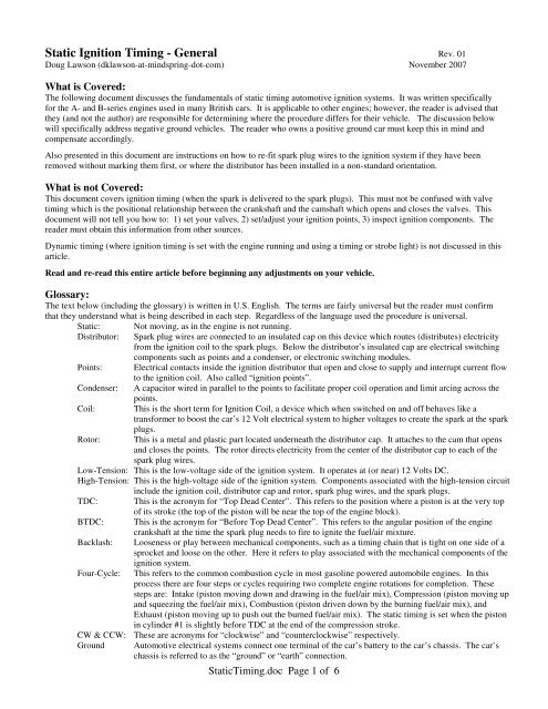
Theory of Operation:<br />
In the discussions that follow, all electrical polarity mentioned is for negative ground cars.<br />
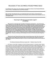
A basic understanding of the coil and its operation is necessary to understand what is to be achieved in static timing. The<br />
figure below shows a simplified schematic of the Kettering ignition system using points and a condenser. In electronic<br />
ignitions an electronic module replaces the points and condenser but serves the same function. Succinctly, when the coil is<br />
supplied battery voltage on its (+) terminal AND the ignition points in the distributor are closed, current flows through the<br />
ignition coil to chassis ground. This creates a magnetic field inside the coil. As the crankshaft in the engine rotates, it turns a<br />
cam inside the distributor (at 1/2 engine speed). The cam in the distributor opens the points and disrupts current flow through<br />
the coil. When the current stops flowing through the coil, its magnetic field collapses and this creates a high voltage spike on<br />
the coil’s high-tension or secondary windings. The high voltage spike is delivered via the rotor, distributor cap, and spark plug<br />
wires to the appropriate spark plug.<br />
For the engine to run efficiently and develop the proper power, the spark must occur at the right time. This is controlled by<br />
adjusting the position at which the cam in the distributor opens the points relative to the position of the crankshaft (the<br />
distributor body position is adjusted so the points open at the correct crankshaft position). Most engines (for reasons beyond<br />
the scope of this document) require the static ignition timing be set so the ignition points open several degrees before the piston<br />
reaches top dead center (BTDC). Setting the static timing is a simple task but care needs to be taken when making these<br />
adjustments that they are being carried out for the correct cylinder at the correct step in the four-cycle process. (Typically this<br />
is with cylinder #1 several degrees BTDC on the end of the compression stroke).<br />
<strong>Ignition</strong> System Schematic (Negative Ground)<br />
<strong>Static</strong><strong>Timing</strong>.doc Page 2 of 6
Preliminary Adjustments:<br />
Various maintenance steps need to be carried out before adjusting the ignition timing. Before proceeding the reader<br />
must carefully dress (or replace) and set the gap of the points. The reader must also inspect all the ignition<br />
components replacing any that are suspect.<br />
Prior to proceeding, remove the distributor cap and have an assistant turn the engine over on the starter. Observe<br />
and record the normal direction of rotation for 1) the engine, and 2) the rotor in the distributor. The A-series and Bseries<br />
engines have clockwise (CW) crank rotation when looking at the front (radiator fan end) of the engine and<br />
their distributor rotors turn counterclockwise (CCW) when observed looking straight down on them. On A- and Bseries<br />
engines #1 cylinder is closest to the radiator fan.<br />
NOTE: Any mention of rotation direction in subsequent paragraphs refers to what is standard on British A- and Bseries<br />
engines. The reader MUST note where this is different from their car and adjust the steps accordingly.<br />
<strong>Timing</strong> Sequence:<br />
Check service manuals to determine what settings are appropriate for your vehicle (static timing settings, firing<br />
order, and location of timing marks).<br />
<strong>Timing</strong> specifications are typically given in degrees BTDC for the #1 cylinder (or spark plug). Therefore the reader<br />
needs to correctly identify which cylinder is #1 and that it is near (but before) TDC at the end of the compression<br />
stroke before proceeding. This can be determined several ways. When in doubt, the best method is to remove the<br />
valve cover and inspect the valve rocker arms for cylinder #1. When the piston is near TDC on the firing stroke,<br />
the piston should be visible through the spark plug hole and its rocker arms will be loose, indicating that the valves<br />
are fully closed and that cylinder is ready to fire. If the crankshaft is rotated one more full turn, the piston will<br />
again be near TDC, however, this time the rocker arms will be tight (valves open) indicating that the engine is at the<br />
end of the exhaust stroke and ready to begin an intake stroke. The reader is advised to confirm that the engine is<br />
near TDC at the end of the compression stroke before making any changes to the ignition settings.<br />
To static time the engine perform the following steps:<br />
1. Label the spark plug wires, remove them from the spark plugs then remove the spark plugs.<br />
2. Remove the distributor cap from the distributor but leave the spark plug wires attached to it.<br />
3. Locate the timing marks on your engine and determine which are correct for your use.<br />
4. Use one of the following methods to turn your engine over as works best for your car:<br />
• Put the car in neutral and pull the engine over using the tight fan belt and fan, or<br />
• put the car in gear and jack the car up sufficiently to elevate one drive wheel then<br />
rotate the elevated wheel, or<br />
• leave the car in gear on level ground and roll the car to turn the engine over, or<br />
• with the gearbox in neutral, use the appropriate socket on the crank pulley and turn the<br />
engine over using a wrench.<br />
5. Turn the engine only in the normal direction of rotation and stop turning the engine when the desired<br />
timing marks come into alignment. (i.e. Stop at 5 to 8 BTDC on A-series engines). If you overshoot the<br />
desired timing mark, back up past the desired mark by at least 30 degrees, then move forward again to<br />
assure that all the slack and backlash have been taken out of the mechanical components. Remember that<br />
you must stop at the timing marks when the piston is near the end of the compression stroke.<br />
6. Locate the wire connecting the distributor to the coil. Connect your test lamp (or multi-meter) wires<br />
between this coil terminal and a good, bare metal earthing (ground) spot on the engine or car body.<br />
7. For reference, make a small removable paint mark between the distributor body and the engine. (In the<br />
event of some unforeseen problem, the distributor can be set to its original position by re-aligning the paint<br />
marks).<br />
8. Loosen the distributor clamp.<br />
9. Switch ON the ignition (Pertonix/Aldon Ignitor owners read the appendix first). The test lamp may be OFF<br />
or ON.<br />
<strong>Static</strong><strong>Timing</strong>.doc Page 3 of 6
10. If the test lamp is ON, turn the distributor body SLOWLY in the direction you observed the rotor turning<br />
during normal engine rotation until it turns OFF, then continue about 10 or 20 more degrees. If the lamp<br />
was already OFF, turn an additional 10 to 20 degrees in the direction of rotor rotation and stop.<br />
11. SLOWLY turn the distributor body back in the OPPOSITE direction you just turned it until the test lamp<br />
just turns on. You will be turning the distributor body the OPPOSITE direction of rotor rotation.<br />
12. Stop immediately when the test lamp turns on and tighten the distributor clamp.<br />
13. Refit the rotor (if removed), distributor cap, spark plugs, and refit the spark plug wires.<br />
14. Once you have started the engine and are happy with the results, remove the old paint alignment made in<br />
step 7 above and make a new paint mark between the distributor and engine block.<br />
NOTES:<br />
1) The test lamp will turn ON when the points are open and OFF when they are closed. When you turn the<br />
distributor body until the test lamp just turns on (or multi-meter displays 12 Volts) you have located the point where<br />
the coil will fire to create the spark. Locking the distributor down in this position sets the static timing for the<br />
engine.<br />
2) IF you find you have to reset the timing on the side of the road and cannot improvise a test lamp, timing may be<br />
carried out by eye. As above, turn the distributor body in the direction of rotor rotation until you see the points are<br />
fully closed. Stop and turn the distributor body SLOWLY in the opposite direction watching closely for a small<br />
spark at the points which indicates the exact moment that they open. This is equivalent to the test lamp turning<br />
“ON”.<br />
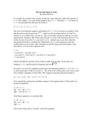
Test Lamp Connections<br />
<strong>Timing</strong> Marks On Early Mini (A-Series Engine)<br />
1/ 4 = TDC<br />
<strong>Static</strong><strong>Timing</strong>.doc Page 4 of 6<br />
Test Lamp<br />
Typical <strong>Timing</strong> Marks
Multi-meter connected to VW (in place of test lamp)<br />
for static timing. 12V = Points open.<br />
Distributor rotor is the light-brown component above<br />
the black, cylindrical distributor housing.<br />
Test Lamp between coil (-) and ground.<br />
(Red wire on coil (-), Black wire on cylinder head stud).<br />
Points are open.<br />
Firing Order:<br />
For various reasons a distributor may have been inserted into an engine block in a “non-standard” orientation. For<br />
this reason the spark plug wires may be arranged on the cap in positions that differ from what is shown in service<br />
manuals. This is not a serious problem. What is important is the firing order. (Air cooled VW owners please see<br />
the appendix. Distributor orientation and spark plug wire placement is important to you).<br />
If the reader has followed the steps outlined in “<strong>Timing</strong> Sequence” above, they have identified when #1 cylinder is<br />
at the top of its compression stroke. Subsequent to that they have set the static timing for #1 cylinder. Installing<br />
the spark plug wires in the correct sequence is a simple extension of that process.<br />
If the engine ran properly before (and the spark plug wires have not been removed from the distributor cap) simply<br />
re-fit the rotor (if removed), the distributor cap, and spark plugs, then reconnect the spark plug wires to the spark<br />
plugs. There is nothing to change.<br />
If for some reason all the spark plug wires were removed or the spark plug wires were not marked prior to removal,<br />
proceed as follows:<br />
1. Complete the <strong>Timing</strong> Sequence described above. (Do not turn the engine after setting the static timing).<br />
2. Fit the rotor to the shaft/cam inside the distributor if it was removed.<br />
3. Fit the distributor cap to the distributor making sure it engages any alignment features that orient it<br />
correctly.<br />
4. Remove the cap again, pulling it slowly straight up.<br />
5. The rotor will be pointing in the direction of a lug and spark plug wire on the distributor cap. Place the<br />
spark plug wire for #1 cylinder on that cap lug/position and connect its other end to the spark plug for #1<br />
cylinder.<br />
6. Refer to your service manual and find the firing order for your engine. (For the A- and B-series British<br />
engines the firing order is 1-3-4-2).<br />
7. Refer to your notes where you recorded the direction of rotor rotation.<br />
8. Sequentially put the spark plug wires on the distributor cap following the direction of rotor rotation and the<br />
firing order listed in your service manual. For the A- and B-Series engines the direction of rotor rotation is<br />
counterclockwise and the order is 1-3-4-2. Therefore, after fitting the spark plug wire for #1 cylinder to the<br />
distributor cap, the next lug CCW on the cap receives the spark plug wire for cylinder #3 and so on.<br />
<strong>Static</strong><strong>Timing</strong>.doc Page 5 of 6
Again, your service manual may show the distributor oriented a different way than you find on your engine and this<br />
may have occurred for several reasons. However, if you were able to static time your car’s ignition, and if any<br />
vacuum advance tubing for the distributor is long enough, and if the spark plug wires are long enough to reach the<br />
appropriate spark plugs there is no problem with rearranging your spark plug wires around the distributor cap as<br />
long as the firing order is maintained.<br />
Appendix:<br />
1) Pertronix/Aldon Ignitor:<br />
There are at least two versions of electronic ignition modules available from Pertronix. The original module<br />
(simply referred to as an Ignitor) can be static timed exactly the same as ignition points. HOWEVER, the ignition<br />
module is not rated for continuous passage of current. Limit the time power is flowing through the Ignitor unit<br />
to less than three minutes, then allow an equal time for cooling before applying power again. Removing power<br />
can be addressed by turning the ignition off between attempts to static time the engine.<br />
A later version of this module is referred to as Ignitor II. This module CANNOT be static timed.<br />
Older Crane/Alison ignitions can be static timed following the procedure above but the author is not familiar with<br />
later units, nor is the author familiar with Lumenition ignitions.<br />
2) Air Cooled Volkswagen Engine Firing Order:<br />
Unlike most engines, the air cooled VW has an asymmetrical distributor cam. The distributor is intentionally<br />
designed to provide slightly different timing for cylinder #3. This altered timing is provided to account for the<br />
higher operating temperature of cylinder #3 due to the proximity of the engine oil cooler. VW owners should pay<br />
close attention to and adjust their distributors to match the installation and firing order photographs shown in their<br />
service manuals.<br />
Rev Date Changes<br />
<strong>Static</strong><strong>Timing</strong>.doc Page 6 of 6