7900 Instrument Stand - Haag-Streit USA
7900 Instrument Stand - Haag-Streit USA
7900 Instrument Stand - Haag-Streit USA
- TAGS
- haag-streit-usa.com

You also want an ePaper? Increase the reach of your titles
YUMPU automatically turns print PDFs into web optimized ePapers that Google loves.
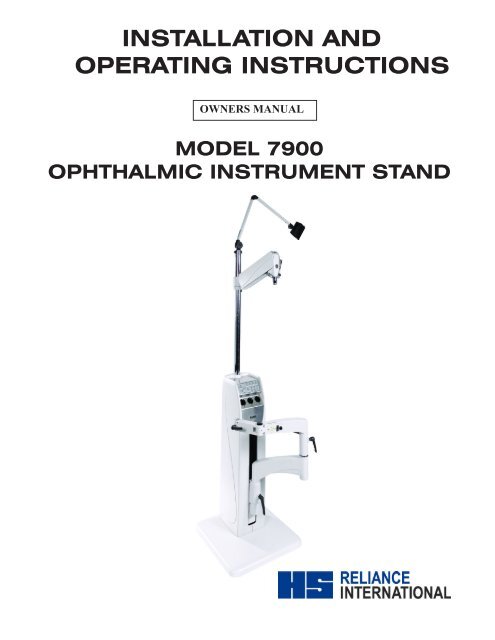
����INSTALLATION AND<br />
OPERATING INSTRUCTIONS<br />
OWNERS MANUAL<br />
MODEL <strong>7900</strong><br />
OPHTHALMIC INSTRUMENT STAND
MADE IN AMERICA<br />
serial number<br />
For your future reference, mark the serial number<br />
in the space provided.<br />
Quality management<br />
system<br />
registered to<br />
iso 9001:2000<br />
iso 13485:2003<br />
Reliance® Medical Products • 3535 Kings Mills Road • Mason, Ohio 45040-2303 • 1-800-735-0357 • www.reliance-medical.com
Table of Contents<br />
imPOrTanT inFOrmaTiOn................................................4<br />
1. inTrODuCTiOn...................................................5<br />
TeChniCal sPeCiFiCaTiOns................................6<br />
2. insTallaTiOn..................................................7<br />
unPaCking...............................................................7<br />
2.1 base unit..........................................................7<br />
2.2 instrument Console/base Cap.......................7<br />
replacement or repair...............................7<br />
2.3 support Column installation..........................8<br />
2.4 Configuring The switches For The b/P ...................8<br />
2.5 auxiliary (Third) arm .............................................9<br />
2.6 refractor suspension arm - Dual lock.........10<br />
2.7 refractor suspension arm - single lock......10<br />
2.8 Overhead lamp..............................................10<br />
2.9 slit lamp arm...............................................10<br />
2.10 Final assembly...........................................12<br />
Console/base Cap..........................................12<br />
2.11 Chair assembly............................................12<br />
2.12 miscellaneous.............................................12<br />
3. OPeraTing insTruCTiOns............................13<br />
3.1 slit lamp arm......................................13<br />
3.2 auxiliary (Third) arm....................................14<br />
3.3 refractor suspension arms........................14<br />
3.4 Overhead lamp............................................14<br />
3.5 instrument Console/base Cap....................14<br />
hand instrument Wells - rechargeable battery<br />
Ty p e ( C o n s o l e o n l y ) . . . . . . . . . . . . . . . . . . . . . . . . . 1 4<br />
3.6 Front Panel Controls.............................15<br />
standby switch (sTbY) ...............................15<br />
auxiliary switch (aux1)................................16<br />
lamp switch (lamp)...........................16<br />
lamp Down switch..................................16<br />
lamp up switch............................................16<br />
binding Post switch (b/P)............................16<br />
b/P Down switch...........................................16<br />
b/P up switch................................................16<br />
Chair base up switch...................................16<br />
Chair base Down switch..............................16<br />
auto switch.................................................16<br />
3.7 Fuses...........................................................17<br />
3.8. eclipse infrared room light Control<br />
system.......................................................................18<br />
Dual Zone vs. single Zone...........................18<br />
incandescent vs. Fluorescent......................19<br />
single Zone...................................................19<br />
Dual Zone......................................................19<br />
sWiTChPaCk #1 (sW1)......................................21<br />
sWiTChPaCk #2 (sW2).....................................22<br />
Programming single Zone room lights....23<br />
Programming Dual Zone room lights......24<br />
T r O u b l e s h O O T i n g g u i D e . . . . . . . . . . . . . . . . . . . . 2 9<br />
Cleaning anD mainTenanCe .......................31<br />
ParTs lisT.........................................................33<br />
model <strong>7900</strong> instrument stand assembly.....35<br />
base assembly.............................................36<br />
roller Frame assembly................................38<br />
Outlet Plate assembly..................................40<br />
back Cover assembly.................................42<br />
slit lamp arm assembly..............................44<br />
model 5250 Dual lock refractor<br />
assemblY...............................................................46<br />
model 5255 single lock refractor<br />
assemblY...............................................................48<br />
model 5380 auxiliary (3rd) arm assembly...50<br />
instrument Console W/O ir assembly........52<br />
instrument Console With ir assembly..........54<br />
instrument Console base Cap assembly W/O Wells<br />
.......................................................................56<br />
instrument Console base Cap assembly With<br />
Wells..................................................58<br />
Wire Diagram - Console<br />
(With and Without ir) ..............................................60<br />
Wire Diagram basecap.................................62<br />
limiTeD WarranTY..........................................67<br />
3
imPOrTanT inFOrmaTiOn<br />
saFeTY sYmblOls<br />
4<br />
!<br />
“Danger”, “Warning”, or “CauTiOn”<br />
The exclamation point within an equilateral<br />
triangle is intended to alert the user to<br />
the presence of important operating and<br />
maintenance (servicing) instructions in this<br />
Installation and Operating Instructions.<br />
“nOTe”<br />
Amplifies a procedure, practice, or condition.<br />
Type B, Applied Part<br />
<strong>Stand</strong>-By<br />
Dangerous Voltage / Shock Hazard<br />
Fuse Rating Specification<br />
Protective Earth Ground<br />
Alternating Current-AC<br />
Safe Working Load<br />
“Attention, Consult Accompanying<br />
Documents”<br />
TransPOrTaTiOn / sTOrage COnDiTiOns<br />
Temperature: Operating: 59 to 104º F<br />
15 to 40º C<br />
Storage: -22 to +140º F<br />
-30 to +60º C<br />
Relative Humidity: Operating: 5 to 95% without<br />
condensation<br />
Storage: 10 to 100%<br />
IN-<strong>7900</strong>
1. inTrODuCTiOn<br />
1.1. This Installation and Operating Instructions contains<br />
information applicable only to the Reliance® Model <strong>7900</strong><br />
ophthalmic instrument stand also known as floor unit.<br />
1.2. Whenever you see the symbols shown below, heed their<br />
instructions! Always follow safe operating and maintenance<br />
practices.<br />
“Danger”- The Danger sYmbOl<br />
iDenTiFies sPeCial insTruCTiOns Or<br />
PrOCeDures WhiCh, iF nOT COrreCTlY<br />
FOllOWeD, COulD resulT in lOss OF liFe<br />
Or PersOnal inJurY.<br />
‘’Danger” - le sYmbOle De Danger<br />
iDenTiFie les insTruCTiOns sPÉCiales<br />
O u l e s P r O C É D u r e s Q u i , s i n O n<br />
COrreCTemenT suiVi, POurraienT aVOir<br />
COmme COnsÉQuenCe la PerTe De Vie Ou<br />
De blessures.<br />
“Warning”- The Warning sYmbOl<br />
iDenTiFies sPeCial insTruCTiOns Or<br />
PrOCeDures WhiCh, iF nOT COrreCTlY<br />
FOllOWeD, COulD resulT in PersOnal<br />
inJurY.<br />
« aVerTissanT » - le sYmbOle<br />
D ’ aV e r T i s s e m e n T i D e n T i F i e l e s<br />
insTruCTiOns sPÉCiales Ou les<br />
PrOCÉDures Qui, sinOn COrreCTemenT<br />
suiVi, POurraienT aVOir COmme<br />
COnsÉQuenCe Des blessures.<br />
“CauTiOn”- This caution symbol identifies<br />
special instructions or procedures which, if<br />
not strictly observed, could result in damage<br />
to or destruction of equipment.<br />
« aTTenTiOn » - ce symbole d’attention<br />
identifie les instructions spéciales ou les<br />
procédures aux lesquelles, sinon strictement<br />
observés, pourrait avoir comme conséquence<br />
les dégâts ou la destruction du matériel.<br />
“nOTe”- Note indicates points of particular or<br />
additional information.<br />
« nOTe » - la note indique des remarques<br />
d’information particulière ou supplémentaire.<br />
1.3 Should your product not perform properly, or if you<br />
have any questions concerning the use and care of any<br />
Reliance® product, contact the Reliance® Distributor,<br />
where you purchased this product or contact the Technical<br />
Service Department, Reliance® Medical Products, Inc.,<br />
3535 Kings Mills Road, Mason, Ohio 45040-2303, or call<br />
(800) 735-0358.<br />
nOTe: Always have the model number and serial<br />
number available before contacting Reliance® or<br />
your authorized Reliance® Distributor.<br />
nOTe: Ayez toujours le numéro et le numéro<br />
de série de type disponibles avant Reliance®<br />
entrant en contact ou votre distributeur autorisé<br />
de Reliance®.<br />
“ClassiFieD bY CanaDian sTanDarDs<br />
assOCiaTiOn® Csa WiTh resPeCT TO<br />
eleCTriC shOCk, Fire anD meChaniCal<br />
haZarDs OnlY in aCCOrDanCe WiTh ieC<br />
60601-1.”<br />
According to Clause 5 in IEC 60601-1, sec 6.8.1, this unit<br />
is classified by the following:<br />
• The type of protection against electric shock: EQUIPMENT<br />
energized from an external electrical power source:<br />
CLASS I EQUIPMENT<br />
• The degree of protection against electric shock: TYPE<br />
B EQUIPMENT<br />
• The degree of protection against harmful ingress of<br />
water: ORDINARY DEGREE<br />
• The degree of safety of application in the presence of a<br />
FLAMMABLE ANAESTHETIC MIXTURE WITH AIR or WITH<br />
OXYGEN OR NITROUS OXIDE: EQUIPMENT not suitable<br />
for use in the presence of a FLAMMABLE ANAESTHETIC<br />
MIXTURE WITH AIR or WITH OXYGEN OR NITROUS<br />
OXIDE<br />
• The mode of operation: CONTINUOUS OPERATION<br />
IN-<strong>7900</strong> 5
6<br />
Warning: TO PreVenT Fire Or shOCk<br />
haZarD, DO nOT exPOse This aPPlianCe<br />
TO rain Or mOisTure.<br />
aTTenTiOn: POur PrÉVenir le risQue<br />
D’inCenDie Ou De ChOC, n’exPOseZ<br />
Pas CeT aPPareil À la Pluie Ou À<br />
l’humiDiTÉ.<br />
TeChniCal sPeCiFiCaTiOns<br />
rating for 120V instrument stand<br />
This equipment is rated Class I, Type B<br />
Equipment Model<br />
<strong>Instrument</strong> <strong>Stand</strong> <strong>7900</strong><br />
Volts Hertz Amps<br />
120V 50/60 12.0<br />
Class I Type B<br />
�<br />
��������<br />
���������<br />
����������<br />
rating for 230V instrument stand<br />
This equipment is rated Class I, Type B<br />
Equipment Model<br />
<strong>Instrument</strong> <strong>Stand</strong> <strong>7900</strong><br />
Volts Hertz Amps<br />
230V 50/60 6.0<br />
Class I Type B<br />
�<br />
��������<br />
���������<br />
����������<br />
U.S. Patent No.<br />
D503,233 D512,507 5,717,480<br />
D504,515 D514,701 5,907,387<br />
D506,257 D424,200 6,264,329<br />
imPOrTanT user Warnings<br />
Warning- exPlOsiOn: This sTanD musT<br />
nOT be useD in The PresenCe OF Flammable<br />
anesTheTiCs.<br />
“aVerTissanT” - DÉCOmPOsiTiOn : CeTTe<br />
gabariT ne DOiT Pas êTre uTilisÉe en<br />
PrÉsenCe Des anesThÉsiQues inFlammables<br />
POTenTial eleCTrOmagneTiC or OTher<br />
inTerFerenCe<br />
This equipment generates, uses and can radiate radio<br />
frequency energy and, if not installed and used in accordance<br />
with the instructions, may cause harmful interference to other<br />
devices in the vicinity. However, there is no guarantee that<br />
interference will not occur in a particular installation.<br />
If this equipment does cause harmful interference to other<br />
devices, which can be determined by turning the equipment<br />
off and on, the user is encouraged to try to correct the<br />
interference by one or more of the following measures:<br />
• Reorient or relocate the receiving device.<br />
• Increase the separation between the equipment.<br />
• Connect the equipment into an outlet on a circuit different<br />
from that to which the other device(s) are connected.<br />
• Consult the manufacturer or field service technician for<br />
help.<br />
This product contains lead. Check with local ordinance or<br />
laws for proper disposal.<br />
IN-<strong>7900</strong>
2. insTallaTiOn<br />
2.1. unpacking<br />
2.1.1. base unit<br />
2.1.1.1 Remove all external shipping tapes and wrappings.<br />
Remove the base unit from the skid and set it in the desired,<br />
final location.<br />
2.1.1.2 Loosen the two screws that hold the back cover<br />
(Figure 1) in place, located in bottom of cover. Cover lifts<br />
off the base unit.<br />
2.1.1.3. Squeeze, the slit lamp arm release lever (Figure<br />
1) and at the same time push down on slit lamp arm. Arm<br />
should move approximately 1/4 inch. Release the lever to<br />
set the slit lamp arm lock.<br />
2.1.1.4. Inside the rear of the unit, remove the wood brace<br />
beneath the counterbalance weights and the cords which<br />
hold incremental weights to the large weight. While pushing<br />
firmly down (50 pounds force) on the slit lamp arm, again<br />
squeeze the lock release lever. Allow the slit lamp arm to<br />
rise to its full height and again release the lever.<br />
Warning- WiTh WeighT braCe remOVeD,<br />
arm assemblY Will rise abruPTlY iF<br />
release leVer is DePresseD.<br />
aVerTissanT -lOrsQue le blOQueur<br />
De DÉPlaCemenT esT reTirÉ, le<br />
bras COnTrebalanCÉ remOnTera<br />
PrOmPTemenT si le leVier Du Frein esT<br />
enFOnCÉ.<br />
2.2. instrument Console/base Cap<br />
CauTiOn- The power supply cord should not<br />
be connected to the power supply during the<br />
installation process.<br />
aVerTisseZ -le cordon d’alimentation ne<br />
doit pas être connecté au secteur électrique<br />
pendant d’installation.<br />
Refractor<br />
Suspension<br />
Arm<br />
Auxiliary<br />
(Third) Arm<br />
<strong>Instrument</strong><br />
Console or<br />
Base Cap<br />
Handle<br />
Release Lever<br />
Slit Lamp Arm<br />
Handle<br />
Overhead<br />
Lamp<br />
Monitor<br />
Arm<br />
Figure 1<br />
Support<br />
Column<br />
31”<br />
(787.4 mm)<br />
16”<br />
(406.4 mm)<br />
7 1/2 ”<br />
(190.5 mm)<br />
nOTe: If you are installing room light controls<br />
on this instrument stand, also refer to the “Eclipse<br />
Room Light Control Operating Instructions<br />
Section.”<br />
nOTe : Si vous installez le système de contrôles<br />
d’éclairage sur le support ophtalmique, veuillez<br />
suivre les consignes d’installation en vous référant<br />
au manuel d’instruction du système de contrôle<br />
d’éclairage éclipse.<br />
2.2.1. replacement or repair<br />
Back<br />
Cover<br />
Wood Brace<br />
(Inside)<br />
IN-<strong>7900</strong> 7<br />
Base<br />
Unit<br />
In the event that the instrument console or cap must be<br />
mounted or removed for replacement or repair purposes, it<br />
will be necessary to remove the back cover and disconnect<br />
the eight connectors from the console. To continue removing<br />
the console, remove the three Phillips Head screws from the
8<br />
mounting tabs then lift the console out from the front of the<br />
unit.(See Figure2)<br />
To install a console, connect the four connectors on top of<br />
the base to the matching connectors hanging from the back<br />
of the console. The lamp jumper cable will drop throught the<br />
large opening and be connected to the matching connector<br />
that hangs from underneath the support column. Figure 2<br />
illustrates the connections that must be made. Align the three<br />
mounting tabs in the base unit with the matching holes in the<br />
console and attach with Phillps Head screws.<br />
2.3. support Column installation<br />
Remove Philips Head shipping screw. Unwrap the support<br />
column. Remove the column support pin and the collar from<br />
the instruction manual bag. Insert the column in the hole at<br />
Chair Control<br />
(Ref)<br />
Overhead<br />
Lamp<br />
Slit Lamp<br />
Arm from<br />
Roller Frame<br />
Mounting<br />
Tabs<br />
Ground from<br />
AC Input<br />
Figure 2<br />
Ground from 3rd Arm &<br />
Slit Lamp<br />
AC Input<br />
from Outlet<br />
Plate<br />
3rd Arm<br />
from Back<br />
Cover<br />
Aux from<br />
Back Cover<br />
the top of the base unit. Line up the hole in the column with<br />
the hole in the base unit and insert the pin. Note that the<br />
small screw at the top of the column faces the rear of the<br />
unit. Tighten the set screws under the support pin. Remove<br />
set screw from bag and install where shipping screw had<br />
been. Slide the collar down firmly against the console/base<br />
cap. Insert and tighten set screw.<br />
2.4. Configuring The switches For The b/P<br />
Switchpack SW2 on the console must be configured<br />
for proper operation of the stand. Individual switches 1,<br />
2 and 3 control the voltage and power to the Indirect<br />
Ophthalmoscope. See Table 1 on Page 8.<br />
Switchpack<br />
(SW2)<br />
Overhead<br />
Lamp<br />
Overhead<br />
Lamp<br />
Jumper<br />
B/P Jumper<br />
from Module<br />
Chair Control<br />
from Outlet<br />
Plate<br />
Switchpack<br />
(SW1)<br />
Optional<br />
Chair<br />
Control<br />
IN-<strong>7900</strong>
TABLE 1<br />
SWITCH SETTINGS FOR B/P VOLTAGES<br />
S W2-1 S W2-2 S W2-3 B /P V OLTAG E<br />
OF F OF F OF F 6V /18W INC ANDE S C ANT<br />
ON OF F OF F 7V INC ANDE S C ANT<br />
OF F ON OF F 12V INC ANDE S C ANT<br />
ON ON OF F NOT DE F INE D<br />
OF F OF F ON 6V /10W HALOG E N<br />
ON OF F ON 6V /18W HALOG E N<br />
OF F ON ON 12V /12W HALOG E N<br />
ON ON ON NOT DE F INE D<br />
PRESS HERE<br />
TO TURN OFF<br />
oFF<br />
SW2<br />
auXiliary<br />
"3rd" arm<br />
ProJeCtor<br />
1 2 3 4 5 6 7 8<br />
PRESS HERE<br />
TO TURN ON<br />
�<br />
��������<br />
���������<br />
����������<br />
���<br />
����<br />
Figure 3<br />
2.5 auxiliary (Third) arm<br />
2.5.1. If supplied, unpack the auxiliary (third) arm. Slide the<br />
clamp member carefully down over the support column until<br />
positioned as shown in Figure 1. Tighten the clamp screw<br />
using the hex key wrench provided.<br />
2.5.2. Position the clamp initially so that the clamp screw is<br />
toward the rear of the unit. If necessary, this position can be<br />
altered to center the rotation of the arm about the column<br />
(300°) within the desired range of movement.<br />
2.5.3. Springs are used to counterbalance the instrument<br />
mounted on the arm. Adjustment of the springs is by means<br />
of a screw which is accessible upon removal of plug button.<br />
Rotating the screw clockwise increases the tension. With<br />
the instrument in place, adjust the screw for the 20 to 50<br />
pounds.<br />
If used with a console, plug the third arm into the<br />
connector marked “3RD ARM.” Securely attach the green<br />
ground wire to the stud with the nut provided. If used with a<br />
base cap, plug the third arm into the connector on the back<br />
of the base cap housing. Once again, securely attach the<br />
green ground wire to the stud with the nut provided.<br />
Binding<br />
Posts<br />
IN-<strong>7900</strong> 9<br />
!
10<br />
2.6. refractor suspension - Dual lock<br />
2.6.1. Unpack the refractor suspension arm. Slide the<br />
clamp member carefully down over the support column until<br />
positioned as shown in Figure 1. Tighten the clamp screw<br />
securely, using the hex key wrench provided.<br />
2.6.2. Note that the chrome plug button in the front of<br />
the assembly covers the counterbalance spring adjusting<br />
screw. If necessary, after the instrument is attached to the<br />
suspension, remove this button and adjust the screw, turning<br />
it clockwise to increase tension. Optimum adjustment is<br />
reached when the suspension barely supports the weight<br />
at the upper limit of it’s travel. The suspension will support<br />
instruments weighing a maximum of 20 pounds.<br />
2.7. refractor suspension-single lock<br />
2.7.1. Unpack the refractor suspension. Slide the clamp<br />
member carefully down over the support column until<br />
positioned as shown in Figure 1. Tighten the clamp screw<br />
securely, using the hex key wrench provided.<br />
2.7.2. After the refractor is mounted on the suspension<br />
arm, the counter balance spring may require adjustment.<br />
The 1/2” adjustment screw may be found just below the<br />
cover by viewing the suspension from the support column.<br />
Turning the screw clockwise will increase tension. Optimum<br />
adjustment is reached when the suspension barely supports<br />
the weight at the upper limit of it’s travel. The suspension<br />
arm will support instruments weighing a maximum of 20<br />
pounds.<br />
2.8. Overhead lamp<br />
2.8.1. Unpack the lamp assembly. Remove the small screw<br />
near the top of the support column. Feed the plug and coiled<br />
extension cord into the tip of the support column until the<br />
lamp support member can be inserted into the column.<br />
Replace the screw previously removed.<br />
2.8.2 Remove the support tube pin (Item11, Fig. 20) to<br />
allow the lamp cord plug to drop free of the support column.<br />
Replace the support pin, being careful not to pinch the lamp<br />
cord.<br />
Insert the plug from the overhead lamp extension into the<br />
matching connector hanging down from the console in the<br />
rear of the unit.<br />
When all connections have been completed, replace the<br />
back cover.<br />
2.9 slit lamp arm<br />
2.9.1. After slit lamp arm is unpacked and set into place,<br />
the option of changing the instrument stand can be done at<br />
this time. For example if the unit is order as a right-handed<br />
and needed to be changed to left-handed unit; follow the<br />
listed instructions below.<br />
2.9.1.1 To convert the Slit Lamp Arm to a left-handed unit,<br />
remove the four (4) #8-32 Screws that hold the Cover<br />
Plates with the Outlet and Rocker Switch. Carefully pull<br />
the Plates off of the Upper Arm. Loosen the center Screw<br />
holding the two plates together but do not completely<br />
remove it. Pull the two Plates apart and rotate them so<br />
the Outlet and Rocker Switch are now on the opposite<br />
side of the Upper Arm. Place the Plates back into the<br />
recessed area of the Upper Arm. Be careful not to pinch<br />
any wires between the Plates and the Upper Arm when<br />
making this change.<br />
2.9.1.2 Loosen the three Set Screws that lock the Arm<br />
Extension in place at the end of the Slit Lamp Arm. Loosen<br />
the Black Knob on top of the Slit Lamp Arm.Rotate Arm<br />
Extension so it is approximately 60 degrees from the side<br />
of the Upper Arm of the Slit Lamp Arm and tighten the Set<br />
Screws. Tighten the Black Knob on top of the Slit Lamp<br />
Arm. Remove Adjustable Handle and Plug Button from the<br />
Arm Extension and place them on the opposite side they<br />
were on. (See Figure 4) and (See Figures 4a, 4b, 4c, 4d<br />
page 10 and Figure 27 page 42 for details.)<br />
Voltage laBel<br />
outlet<br />
oPPosite side<br />
uPPer arm CoVer Plate, Plain<br />
uPPer arm CoVer Plate<br />
#8-32 tHms<br />
PusH Button sWitCH W/ ir (sHoWn)<br />
Plug Button W/o ir<br />
Figure 4<br />
roCKer<br />
sWitCH<br />
#8-32 PHms<br />
IN-<strong>7900</strong>
Figure 4a Figure 4b<br />
Figure 4C Figure 4D<br />
reference to changing the instrument stand from a right-handed to a left-hand unit.<br />
IN-<strong>7900</strong> 11
12<br />
2.10. Final assembly<br />
2.10.1. Console<br />
If an additional instrument is to be connected to the binding<br />
posts or if any auxiliary equipment is to be plugged into<br />
the”AUX” power connector, make these connections at<br />
this time.<br />
2.11. Chair assembly<br />
2.11.1 The chair control switches located on the floor unit<br />
may control any Reliance® low voltage chair. Refer to the<br />
chair instructions for unpacking and assembling the chair.<br />
2.11.2. A chair control cable is provided to control the<br />
vertical movement of the chair base from the floor unit.<br />
One end of the cable is to be inserted into the black circular<br />
receptacle on the Outlet Plate Assembly. See Figure 5. The<br />
other end of the cable is to be inserted into the mating<br />
receptacle marked “CHAIR CONTROL CABLE” in the rear of<br />
your Reliance® chair.<br />
2.12. miscellaneous<br />
Figure 5<br />
2.12.1. When attaching an instrument to the slit lamp arm,<br />
note the thrust bearing which should be in place between<br />
the instrument and the arm.<br />
2.12.2. Proper balance of an instrument on the slit lamp<br />
arm is achieved by adding or removing counter-balance<br />
weights as shown in Figure 6. See Page 12 for a table of<br />
weight settings.<br />
2.12.3 Finally, plug the power cord into a wall receptacle<br />
and check all electrical functions as described in the<br />
Installation and Operating Instructions. If all functions are<br />
normal, reattach the base unit rear cover.<br />
2.12.4 To disconnect power to <strong>Instrument</strong> <strong>Stand</strong> unplug<br />
power cord from wall receptacle.<br />
nOTe: Outlet wires are hot.<br />
nOTe : Les fils de sortie sont chauds<br />
CauTiOn-“accessory equipment connected<br />
to the analog and interfaces must be certified<br />
according to the respective ieC standards<br />
(i.e. ieC 950 for data processing equipment<br />
and ieC 601-1 for medical equipment).<br />
Furthermore all configurations shall comply<br />
with the system standard ieC 601-1-1.<br />
everybody who connects additional equipment<br />
to the signal input part or output part<br />
configures a medical system, and is therefore<br />
responsible that the system complies with<br />
the requirements of ieC 601-1-1. if in doubt,<br />
consult the technical services department or<br />
your local representative.”<br />
equipment with siP/sOP connectors should<br />
either indicate the connected equipment<br />
comply with ieC 601-1 and/or ieC 601-<br />
1-1 harmonized national standard or the<br />
combination should be evaluated.<br />
aTTenTiOn- “les équipements branché sur<br />
le support ophtalmique doivent répondre aux<br />
normes ieC (i.e. ieC 950 pour le matériel<br />
informatique et le ieC 601-1 pour le matériel<br />
médical). en outre toutes les configurations<br />
devront étre conformes á la norme ieC<br />
601-1-1.<br />
Tout personne qui branché un équipement<br />
supplémentaire au systéme doit s’assurer<br />
que cet équipement répond aux normes<br />
médicales ieC 601-1-1 et en est responsable.<br />
en cas de doute, consultez le service<br />
technique de votre distributeur ou votre<br />
préposé technique local.”<br />
le matériel avec des connecteurs de type<br />
siP/sOP devront être conformes à la norme<br />
ieC 601-1 et/ou être conformes à la norme<br />
nationale harmonisée ieC 601-1-1.<br />
IN-<strong>7900</strong>
3. OPeraTing insTruCTiOns<br />
3.1. slit lamp arm<br />
3.1.1. This arm is counterbalanced by means of weights<br />
and all its movements are controlled manually.<br />
3.1.2. The vertical lock for this arm is controlled by the<br />
release lever located under the upper arm. (See Figure 1),<br />
grip the upper arm and depress the release lever to unlock<br />
the arm. Releasing the release lever will lock vertical travel<br />
in both directions.<br />
SLIT LAMP<br />
TABLE<br />
Warning- arm Will rise abruPTlY iF<br />
release leVer is DePresseD anD arm<br />
is nOT COunTer-balanCeD.<br />
aVerTissanT- le bras COnTrebalanCÉ<br />
remOnTera PrOmPTemenT si le leVier<br />
Du Frein esT enFOnCÉ eT Que le bras<br />
n’esT Pas COnTrebalanCÉ.<br />
BEARINGS<br />
OUTER ARM<br />
SET SCREWS<br />
(6)<br />
Figure 6<br />
LEVELING<br />
SLEEVE<br />
OUTERMOST<br />
HANDLE<br />
3.1.3. Incremental weights are added or removed to<br />
achieve proper balance in accordance with the weight<br />
settings-slit lamp arm chart. (See Figure 7).<br />
3.1.4. The handle under the innermost pivot point of<br />
the slit lamp arm (Figure 1), is to restrain rotation of the<br />
complete arm assembly. The handle at the intermediate<br />
joint on the slit lamp arm locks rotation of the outer arm<br />
section. The handle and set screws directly under the slit<br />
lamp locks rotation of the outer arm section. The handle<br />
directly under the slit lamp locks rotation of the instrument<br />
about its pivot point.<br />
instrument gross<br />
weight-lbs.(kg)<br />
12-16 ( 5.44-7.25) None<br />
16-20 ( 7.25-9.0) Light<br />
20-23 ( 9.0-10.43) Medium<br />
23-25 ( 10.43-11.34) Heavy<br />
incremental weights<br />
25-28 ( 11.34-12.7) Light, Medium<br />
28-30 ( 12.7-13.6) Light, Heavy<br />
30-33 ( 13.6-14.97) Medium, Heavy<br />
33-35 ( 14.97-15.88) 2 Heavy<br />
35-38 ( 15.88-17.24) Light, Medium, Heavy<br />
38-40 ( 17.24-18.14) 1 Light, 2 Heavy<br />
40-43 ( 18.14-19.5) 1 Medium, 2 Heavy<br />
43-45 ( 19.5-20.41) 3 Heavy<br />
45-48 ( 20.41-21.77) 1 Light, 1 Medium, 2 Heavy<br />
48-50 ( 21.77-22.68) 1 Light, 3 Heavy<br />
50-53 ( 22.68-24.04) 1 Medium, 3 Heavy<br />
53-55 ( 24.04-24.95) 4 Heavy<br />
55-58 ( 24.95-26.31) 1 Light, 1 Medium, 3 Heavy<br />
58-60 ( 26.31-27.22) 1 Light, 4 Heavy<br />
Weight settings-slip lamp arm Chart<br />
3.1.5. The outer end of the slit lamp arm contains a sleeve<br />
and six set screws for field re-leveling of the instrument, if<br />
necessary. A hex key wrench (1/8) and a small, accurate<br />
level will be required. Remove the instrument from the table<br />
and refer to Figure 6.<br />
Warning- WiTh insTrumenT remOVeD,<br />
arm Will rise abruPTlY iF release<br />
leVer is DePresseD.<br />
aVerTissanT- lOrs Du reTraiT<br />
D’insTrumenT, le bras COnTrebalanCÉ<br />
remOnTera PrOmPTemenT si le lÈVera<br />
Du Frein esT enFOnCÉ.<br />
The outermost handle must be into the sleeve, but not<br />
tightened. Rotate the slit lamp arm to the examining position<br />
and tighten the other (2) handles. It may be necessary to<br />
loosen several set screws to reposition screws securely<br />
and check level.<br />
IN-<strong>7900</strong> 13
14<br />
Figure 7<br />
3.1.6. The handle on the outermost knob can be adjusted<br />
to any preferred, locked position. Simply pull out on handle,<br />
rotate as desired, and release.<br />
3.1.7. The outer arm contains an outlet for instrument<br />
power, and a rocker switch to control vertical movement<br />
of the chair. The Chair Control Cable (Item 17, Figure 22)<br />
must be installed. (refer to Section 2.10). Depress the “UP”<br />
arrow on the switch to raise the chair. Depress the “Down”<br />
arrow to lower the chair.<br />
nOTe: Switch action is momentary; but may<br />
be programmed to function as maintained<br />
depending on the chair model. See chair manual<br />
for programming instructions.<br />
n O T e : L’action de contact est<br />
momentanée ; mais peut être programmé<br />
pour fonctionner comme mis à jour selon<br />
le modèle de présidence. Voir le manuel<br />
de présidence pour des instructions de<br />
programmation.<br />
3.2. auxiliary (Third) arm<br />
3.2.1. Three handles control all motions of this arm<br />
assembly. The handle nearest the column controls rotation<br />
about the column. The handle at the pivot point of the outer<br />
arm controls both vertical movement and the rotation of the<br />
outer arm. The handle in the outer arm controls rotation of<br />
the instrument at the outermost pivot points.<br />
3.2.2. Adjustment of the spring counterbalance is as<br />
described in the Installation and Operating Instructions,<br />
Section 2.5.3. Plug the power cord into back cover.<br />
3.3. refractor suspension<br />
3.3.1. If the refractor suspension assembly is of the dual<br />
lock style, thehandle nearest the support column controls<br />
the clamp for locking rotation of the entire assembly about<br />
the column. The lever locks both vertical movement and<br />
rotation of the outer arm. If the refractor assembly is of the<br />
single lock style, the movements of the assembly around<br />
the column, the vertical position of the refractor and it’s<br />
rotation are all controlled by the single handle located<br />
below the arms.<br />
3.3.2. Refer to the Installation and Operating Instructions<br />
2.6 or 2.7 for the method of adjusting the counterbalancing<br />
spring.<br />
3.4. Overhead lamp<br />
3.4.1. Movements of the overhead lamp arms are<br />
controlled by friction and spring-compensated joints, each<br />
of which is adjustable. Tighten all three knobs with moderate<br />
hand pressure. This will allow you to move to move the lamp<br />
easily. The lamp should hold its position without repeated<br />
knob adjustments. The lamp has an ON/OFF switch located<br />
at the top of the head, which can be controlled separately<br />
from the instrument stand.<br />
3.5. instrument Console/base Cap<br />
3.5.1. The instrument console or Base Cap contains all<br />
electrical controls for the entire unit. Refer to Figure 8, 9<br />
& 10 for the location of controls.<br />
3.5.2. hand instrument Wells - rechargeable<br />
battery Type (Console only)<br />
3.5.2.1. The rechargeable battery type well is internally<br />
connected to the charging circuit at the factory and will<br />
charge instrument 3.5V NiCd batteries as long as the<br />
instrument handle is fully seated in the well.<br />
3.5.2.2. An indicator light (LED), located below each<br />
rechargeable well is supplied as a visual aid for determining<br />
that instrument is properly seated in the well and is<br />
recharging.<br />
IN-<strong>7900</strong>
CauTiOn- The lamp inside the instrument<br />
must be turned off before inserting the<br />
handle into the well. also, the wells will<br />
charge continuously as long as the power<br />
supply cord is attached to the floor unit.<br />
aVerTisseZ- l’ampoule de l’instrument<br />
doit être éteint avant de l’insérer dans le<br />
puits de charge et les puits chargeront<br />
continuellement la pile de l’instrument tout<br />
aussi longtemps que le support ophtalmique<br />
sera branché sur le secteur électrique.<br />
Figure 8<br />
WiThOuT inFrareD<br />
Figure 9<br />
WiTh inFrareD<br />
Figure 10<br />
baseCaP<br />
3.6. Front Panel Controls<br />
3.6.1. The controls for the stand are located on the panel<br />
above the instrument wells. Refer to Figure 6, 7 and 8 for<br />
identification of the various controls.<br />
3.6.1.1. standby switch (sTbY)<br />
• Turns secondary power ON and OFF to the system.<br />
• Turns the STBY, BASE, and AUTO LED’s ON.<br />
• Applies MAIN power to the S/L ARM and AUX power<br />
connectors if on.<br />
• Disables all system functions, except charging of the<br />
instrument wells when in the OFF position.<br />
IN-<strong>7900</strong> 15
16<br />
Warning- main POWer (120VaC Or<br />
240VaC) is alWaYs PresenT insiDe<br />
The sYsTem When The POWer COrD is<br />
PluggeD inTO The Wall.<br />
aVerTissanT- l’alimenTaTiOn ÉleC-<br />
TriQue De (120VaC Ou 240VaC) esT TOu-<br />
JOurs PrÉsenTe À l’inTÉrieur Du suP-<br />
POrT OPhTalmiQue QuanD Celui-Ci esT<br />
branChÉ sur le rÉseau ÉleCTriQue.<br />
3.6.1.2. auxiliary switch (aux)<br />
• Turns MAIN power ON and OFF to the AUX power<br />
connector.<br />
• Turns the AUX LED ON when MAIN power is applied to the<br />
AUX power connector.<br />
• The primary purpose of the switch is to turn the projector<br />
ON and OFF.<br />
3.6.1.3. lamp switch (lamp)<br />
• Turns the overhead lamp ON and OFF.<br />
• Turns the lamp ON at 50% intensity when the switch is<br />
pressed for the first time after the system’s power cord<br />
is plugged into the wall. Afterwards, the light will turn ON<br />
at its previous intensity level.<br />
• Turns the LAMP LED ON when power is applied to the<br />
overhead lamp.<br />
3.6.1.4. lamp Down switch<br />
• Decreases the intensity of the overhead lamp.<br />
3.6.1.5. lamp up switch<br />
• Increases the intensity of the overhead lamp.<br />
3.6.1.6 binding Post switch (b/P)<br />
• The B/P Switch is enabled when Switch 5 of SW2 is turned<br />
OFF. See Table 1.<br />
• When enabled, turns power to the binding posts (Indirect<br />
Ophthalmoscope) ON and OFF.<br />
• Turns the B/P LED ON when power is applied to the<br />
Ophthalmoscope.<br />
• When disabled, the B/P Switch has no function. Power to<br />
the Ophthalmoscope is controlled by the optional hanger<br />
assembly.<br />
3.6.1.7. b/P Down switch<br />
• Decreases the intensity of the Indirect Ophthalmoscope.<br />
3.6.1.8. b/P up switch<br />
• Increases the intensity of the Indirect Ophthalmoscope<br />
3.6.1.9. Chair base up switch<br />
• Causes the chair base to raise.<br />
3.6.1.10. Chair base Down switch<br />
• Causes the chair base to lower<br />
3.6.1.12. auto switch<br />
• On a low voltage 980, 7000, 710 or FX920 Chair, this<br />
switch causes the chair base to lower to its lowest position<br />
and the chair top to move to its full upright position.<br />
CauTiOn- The chair will move automatically.<br />
To sTOP chair movement, press the sTOP<br />
switch located on the side of the chair<br />
back.<br />
aVerTisseZ- la chaise ophtalmique se<br />
positionnera automatiquement. Pour<br />
arrêTer le mouvement de la chaise,<br />
appuyez sur le bouton “arrêT” situé du côté<br />
de la chaise.<br />
• On a low voltage 5200, 6200 or FXM920 Chair, this<br />
switch causes the chair base to lower to its lowest<br />
position. The chair top must be manually returned to it’s<br />
full upright position.<br />
CauTiOn- The chair will move automatically.<br />
To sTOP chair movement, press the sTOP<br />
switch located on the side of the chair<br />
back.<br />
aVerTisseZ- la chaise ophtalmique<br />
se positionnera automatiquement. Pour<br />
arrêTer le mouvement de la chaise,<br />
appuyez sur le bouton “arrêT” situé du côté<br />
de la chaise.<br />
• On an older high voltage chair, this switch causes the<br />
chair base to lower to its lowest position. The chair top<br />
does not move.<br />
CauTiOn- The chair will move automatically.<br />
To sTOP chair movement, press either the<br />
base uP or base DOWn switches located<br />
on the floor unit.<br />
aVerTisseZ- la chaise ophtalmique se<br />
positionnera automatiquement. Pour arrêTer<br />
le mouvement de la chaise, appuyez sur le<br />
bouton “hauT” ou “bas” situé sur le pédalier<br />
de la chaise.<br />
IN-<strong>7900</strong>
3.6.2<br />
• The round button under the “B/P” arrows is used to turn<br />
on and off the indirect hanger. The up and down arrows<br />
are used to control the output voltage (i.e. the intensity)<br />
of the indirect bulb.<br />
3.6.3<br />
• The round button under the “LAMP” arrows is used to turn<br />
on and off the overhead lamp. The up and down arrows<br />
are used to control the output voltage (i.e. the intensity)<br />
of the overhead lamp.<br />
3.7. Fuses<br />
�������<br />
Warning- DisCOnneCT FlOOr uniT FrOm<br />
main inPuT POWer beFOre PrOCeeDing<br />
WiTh eleCTriCal insPeCTiOns Or<br />
mainTenanCe.<br />
aVerTissemenT-DÉbranCheZ le<br />
suPPOrT OPhTalmiQue Du rÉseau<br />
ÉleCTriQue POur PrOCÉDer À une<br />
insPeCTiOns Ou mainTenanCe.<br />
CauTiOn- replace fuse(s) as marked. all<br />
fuses must be replaced with a fuse of the<br />
same size and rating. refer to the wiring<br />
diagrams on pages 56-59.<br />
l’aTTenTiOn- remplacement des fusible<br />
(s) tel qu’indiqué. Tous les fusibles doivent<br />
être remplacés avec un fusible de même<br />
taille et de même ampérage et/ou voltage.<br />
référez-vous aux diagrammes de câblage<br />
aux page 56-59.<br />
3.7.1. Floor units contain two fuses located inside the AC<br />
Input Module on the Outlet Plate Assembly.<br />
3.7.2. Consoles and Base Caps contain no additional<br />
fuses.<br />
3.7.3. Fuse replacement (aC input module)<br />
method for removing fuse drawer:<br />
1. The fuse drawer is located above the power cord.<br />
Remove the power cord.<br />
Place a small bladed screwdriver into appropriate slot<br />
(shown above) and push the flat spring towards the<br />
center of the power module until a click is heard. (Click<br />
may not be heard in all cases.) The drawer will come<br />
forward slightly.<br />
Once the flap has been pushed towards the center, the<br />
drawer will extend slightly beyond the power module.<br />
Remove the drawer by pulling it out by your fingers.<br />
CauTiOn- never install the drawer into the<br />
aC input module without fuses.<br />
aTTenTiOn- ne jamais introduire le<br />
module de support des fusibles sans avoir<br />
inséré les fusibles.<br />
IN-<strong>7900</strong> 17<br />
2.<br />
3.<br />
4.<br />
5.
18<br />
3.8. eCliPse rOOm lighT COnTrOl sYsTem<br />
The Eclipse Room Light Control System, available as an<br />
option on the Model <strong>7900</strong> instrument stands with console.<br />
The Eclipse System allows one to control examination room’s<br />
incandescent and/or fluorescent lights from the <strong>Instrument</strong><br />
<strong>Stand</strong>. This infrared (IR) system has a maximum of 16 different<br />
lighting combinations or scenes (dual zone). The Eclipse is<br />
available in either a single or dual zone system.<br />
The Eclipse console has an additional switch for room<br />
light controls (See Figure 11, switch marked “ROOM”) and<br />
a transmitter that attaches to the top of the support pole.<br />
The software in the unit is designed to operate a designated<br />
function on the stand. A signal is sent to a receiver that is<br />
installed in the in place of the room light switch. The signal is<br />
an infrared signal, the same technology as remote control.<br />
The signal tells the receiver what “scene” the lights being<br />
controlled need to go into. A scene is a lighting environment<br />
programmed into the receiver. Each function has its own<br />
scene which the user has the ability to manipulate. For<br />
example, removing the instrument from well #1 is scene 1.<br />
When the handle is removed the software tells the receiver<br />
to go to scene 1, and controls the light as scene 1 has<br />
been programmed.<br />
inFrareD signal<br />
Figure 11<br />
3.8.1. Dual Zone vs. single Zone<br />
3.8.1.1 A Zone refers to a bank of lights controlled by one<br />
room light switch. For example a room with a group of canned<br />
lights controlled by one switch and fluorescent controlled by<br />
another switch has two lighting zones. A dual zone system<br />
allows a scene to operate both zones and program them so<br />
the zones are programmed independently. When a handle is<br />
removed from well #1 the user can have one bank of lights<br />
dim and the other turn completely off. When the handle is<br />
replaced the lights go back to the original settings. A single<br />
zone system can only control one lighting zone.<br />
Dual Zone receiver/standard 2 Zone switch<br />
3.8.1.2. number of scenes<br />
Dual zone has 16 scenes or 8 functions on the instrument<br />
stand that can control room lights.<br />
• Room light switch.<br />
• B/P switch.<br />
• Auxiliary switch.<br />
• Lamp switch.<br />
• Switch on the slit lamp arm.<br />
Single zone is controlled by the room light switch.<br />
• Well #1.<br />
• Well #2.<br />
• B/P switch.<br />
• Switch on the slit lamp arm.<br />
The B/P switch and Slit lamp switch share the same<br />
scene.<br />
3.8.1.3 Program Features<br />
Dual zone system is programmed at the receiver mounted<br />
in the wall (see figure 17), while the single zones uses a<br />
hand held remote to program (see figure 16). The dual<br />
zone system allows one to set a fade rate of the lighting,<br />
while the single zone does not. The single zone requires<br />
the B/P switch and Slit lamp arm switch to share a scene,<br />
while dual zone does not.<br />
3.8.1.4 indirect hanger<br />
Both systems accept a indirect hanger which is mounted to<br />
the back of the pole. The hanger is designed so when the<br />
indirect is lifted off, the room lights go to the desired scene<br />
and the indirect comes on. Use of the hanger supersedes<br />
the B/P switch.<br />
IN-<strong>7900</strong>
3.8.2 incandescent vs. Fluorescent<br />
Both systems can accommodate fluorescent lighting.<br />
3.8.2.1 single Zone<br />
This system can only dim fluorescent. It requires a special<br />
receiver and dimming ballast installed to the lighting system.<br />
Incandescent only requires installing the receiver in lieu of<br />
the standard wall switch.<br />
installation Diagram: single Zone incandescent<br />
120 VaC or 277 VaC<br />
120V<br />
60 Hz<br />
Hot<br />
line<br />
side<br />
neutral<br />
BlaCK<br />
note: See Installation Instructions that comes<br />
with Receiver.<br />
note: Voir les instructions d’installation<br />
accompagnant le récepteur.<br />
BlaCK<br />
load<br />
side<br />
ConneCtion diagram<br />
BlaCK Wire must attaCH to<br />
line side only<br />
BlaCK Wire must attaCH to<br />
load side only<br />
Figure 12<br />
3.8.2.2 Dual Zone<br />
This system can either turn fluorescent on and off or dim.<br />
Turning the fluorescent on and off does require a relay<br />
assembly to be installed. Dimming fluorescent involves<br />
installing a dimming ballast and an interface, figure 20<br />
(note dimming ballast, figure 21 is purchased separate).<br />
Incandescent lighting is a direct install. The receiver replaces<br />
the dual light switches already in the wall.<br />
IN-<strong>7900</strong> 19<br />
load<br />
neutral
20<br />
installation Diagram: Dual Zone Flourescent On/OFF incandescent<br />
120 VaC or 277 VaC<br />
Resistor needs to be mounted. Recommended box to house relay and resistor- 6” x 6” x .04” thick and<br />
made of aluminum.<br />
note: See Grafik Eye for installation of GRX.<br />
Figure 13<br />
note : Voir l’oeil diagramme pour l’installation de GRX.<br />
IN-<strong>7900</strong>
Warning-The eCliPse inFrareD rOOm<br />
lighTs COnTrOl sYsTem musT maTCh<br />
The reQuiremenTs OF The user. iF The<br />
sYsTem is nOT PrOPerlY COnFigureD<br />
beFOre seCOnDarY POWer TO The uniT is<br />
TurneD On Via The sTbY sWiTCh, Damage<br />
TO The sYsTem Or insTrumenT bulbs<br />
maY OCCur.<br />
aVerTissanT-le sYsTÈme De COnTrôle<br />
inFrarOuge D’ÉClairage ÉCliPse DOiT<br />
COrresPOnDre aux COnDiTiOns De<br />
l’uTilisaTeur. si le sYsTÈme n’esT<br />
Pas COrreCTemenT COnFigurÉ aVanT<br />
D’allumer le suPPOrT OPhTalmiQue, Par<br />
le COnTrôle “sTbY”, Des DOmmages au<br />
suPPOrT Ou aux amPOules ÉleCTriQues<br />
PeuVenT se PrODuire.<br />
ECLIPSE ROOM LIGHT SYSTEM<br />
Press Here<br />
to turn oFF<br />
indireCt<br />
BulB ratings<br />
slit lamP<br />
BulB ratings<br />
sW2-1<br />
sW2-2<br />
sW2-3<br />
Hanger<br />
BeeP on<br />
oPen<br />
sW2-7<br />
sW2-8<br />
Press Here<br />
to turn on<br />
oFF<br />
sW2<br />
REAR VIEW OF CONSOLE ASSEMBLY<br />
eCliPse inFrareD rOOm lighT COnTrOls<br />
PrOgramming guiDe<br />
Configuring the system is accomplished by setting dip<br />
switches found on the circuit board. The dip switches<br />
are labeled SW1 and SW2. The following paragraphs<br />
provide the necessary information required to configure<br />
the system.<br />
sWiTChPaCk #1 (sW1)<br />
switch 1<br />
• Turn Switch 1 OFF if your system contains a single-zone<br />
infrared receiver.<br />
• Turn Switch 1 ON if your system contains a dual-zone<br />
infrared receiver (Factory default setting).<br />
1 2 3 4 5 6 7 8<br />
oFF<br />
sW1<br />
1 2 3 4 5 6 7 8<br />
enaBle-on<br />
dual Zone<br />
Well #1<br />
Well #2<br />
Well #3<br />
Binding Post<br />
s/l arm<br />
auXiliary<br />
lamP<br />
switch 2<br />
• Turn Switch 2 ON to enable Well #1 to affect room lights<br />
and fixation lights.<br />
• Turn Switch 2 OFF to disable Well #1 from affecting room<br />
lights and fixation lights.<br />
switch 3<br />
• Turn Switch 3 ON to enable Well #2 to affect room lights<br />
and fixation lights.<br />
• Turn Switch 3 OFF to disable Well #2 from affecting room<br />
lights and fixation lights.<br />
switch 4<br />
• Turn Switch 4 ON to enable Well #3 to affect room lights<br />
and fixation lights.<br />
• Turn Switch 4 OFF to disable Well #3 from affecting room<br />
lights and fixation lights.<br />
switch 5<br />
• If power to the Indirect Ophthalmoscope is controlled by<br />
the B/P Switch on the front panel, turn Switch 5 ON if<br />
you want the B/P Switch to affect room lights.<br />
• Turn Switch 5 OFF if you do not want the B/P Switch to<br />
affect room lights.<br />
switch 6<br />
• Turn Switch 6 ON to enable Slit Lamp Arm Switch to affect<br />
room lights.<br />
• Turn Switch 6 OFF to disable Slit Lamp Arm Switch from<br />
affecting room lights.<br />
switch 7<br />
• Turn Switch 7 ON to enable the AUX1 Switch to affect<br />
room lights.<br />
• Turn Switch 7 OFF to disable the AUX1 Switch from<br />
affecting room lights.<br />
switch 8<br />
• Turn Switch 8 ON to enable the LAMP Switch to affect<br />
room lights.<br />
• Turn Switch 8 OFF to disable the LAMP Switch from<br />
affecting room lights.<br />
IN-<strong>7900</strong> 21
22<br />
SWitchpAck #2 (SW2)<br />
switch 1 through 3<br />
These switches are used to determine the type and voltage of<br />
the Indirect Ophthalmoscope bulb. See the Chart below.<br />
B UL B VOL T AG E A ND T Y P E -IND. OP HT HA L MOS C OP E<br />
S witch 1 2 3<br />
6.5V /18W, Incandescent OF F OF F OF F<br />
R S V D Incandescent ON OF F OF F<br />
R S V D Incandescent OF F ON OF F<br />
R S V D Incandescent ON ON OF F<br />
6V /10W Halogen OF F OF F ON<br />
6V /20W Halogen ON OF F ON<br />
12V /12W Halogen OF F ON ON<br />
R S V D Halogen ON ON ON<br />
switch 4<br />
• Turn Switch 4 ON if your system contains a indirect<br />
hanger (Figure 13) for an Indirect Ophthalmoscope and<br />
you want that hanger to automatically supply power to<br />
the instrument.<br />
note: Turn Switch 5 on SW1 OFF if turning Switch<br />
4 ON.<br />
note: Positionnez le contact 5 á la position<br />
arrêt sur l’interrupteur SW1 et positionnez le<br />
contact 4 EN position MARCHE.<br />
• Turn Switch 4 OFF if your system does not contain a hanger<br />
for an Indirect Ophthalmoscope. In this case, power is<br />
turned ON and OFF to the instrument via the B/P Switch<br />
on the front panel (See Switch 5 on SW1).<br />
switch 5<br />
• If you want your system to beep whenever a switch is<br />
pressed , set Switch 5 ON.<br />
• If you do not want to hear a beep whenever a switch is<br />
pressed, set Switch OFF.<br />
switch 6<br />
• Reserved<br />
switches 7 and 8<br />
These switches are used to determine the type and voltage<br />
of the Slit Lamp bulb. See chart to the above right.(DOES<br />
NOT APPLY TO INSTRUMENT STANDS)<br />
B UL B VOL T AG E A ND T Y P E -S L IT L A MP B UL B<br />
S witch 7 8<br />
6V /4.5A, Incandescent OF F OF F<br />
R S V D ON OF F<br />
6V /20W Halogen OF F ON<br />
12V /30W Halogen ON ON<br />
standby switch (sTbY)<br />
• OFF- Unit is deactivated, except for charging wells.<br />
• ON- Activates all unit functions<br />
Figure 14<br />
(F actory default)<br />
auxiliary switch (aux1)<br />
• Affects the room lights and is programmable.<br />
• See section 3.8.3 for programming instructions if you<br />
have a single-zone infrared receiver.<br />
• See Switch 7 of Switchpack #1 in the Programming<br />
Instructions section of this manual for details.<br />
IN-<strong>7900</strong>
oom switch (rOOm)<br />
• Dual Zone turns the ROOM Lights OFF or ON to a<br />
pre-programmed intensity.<br />
• Single Zone turn ROOM Lights OFF or full ON.<br />
room Down switch<br />
• Decreases the intensity of the ALL room light(s).<br />
room up switch<br />
• Increases the intensity of the ALL room lights(s).<br />
lamp switch (lamP)<br />
• Affects the room lights and is programmable.<br />
• See section 3.8.3 for programming instructions if you<br />
have a single-zone infrared receiver.<br />
• See Switch 8 on Switchpack #1 in the Programming<br />
Instructions Section of this manual for details<br />
binding Post switch (b/P)<br />
• Affects the room lights and is programmable.<br />
• See section 3.8.3 for programming instructions if you<br />
have a single-zone infrared receiver.<br />
• See Switch 5 on Switchpack #1 in the Programming<br />
Instructions Section of this manual for details.<br />
hanger switch<br />
• Affects the room lights and is programmable.<br />
• See Switch 4 on Switchpack #2 in the Programming<br />
Instructions Section of this manual for details.<br />
Hanger<br />
Binding Posts<br />
toggle sWitCH<br />
rHeostat<br />
Figure 15<br />
inDireCT hanger sWiTCh<br />
• See section 3.8.3 for programming instructions if<br />
you have a single-zone infrared receiver.<br />
slit lamp switch<br />
• Affects the room lights and is programmable.<br />
• See section 3.8.3 for programming instructions if you<br />
have a single-zone infrared receiver.<br />
• See Switch 6 on Switchpack #1 in the Programming<br />
Instructions Section of this manual for details.<br />
• Push button at the beginning of Slit Lamp examination,<br />
then push button again after examination is complete.<br />
Well #1<br />
• Controls room light(s) when the rechargeable instrument<br />
is removed from well.<br />
• When the instrument is returned to the well, the room lights<br />
return to Scene #1. See section 3.8.3 for Programming<br />
Instructions.<br />
• See Switch 2 on Switchpack #1.<br />
Well #2<br />
• Controls room light(s) when the rechargeable instrument<br />
is removed from the well.<br />
• When the instrument is returned to the well, the room lights<br />
return to Scene #1. See section 3.8.3 for Programming<br />
Instructions.<br />
• See Switch 3 on Switchpack #1.<br />
Well #3<br />
• Controls room light(s) when the rechargeable instrument<br />
is removed from the well.<br />
• When the instrument is returned to the well, the room lights<br />
return to Scene #1. See section 3.8.3 for Programming<br />
Instructions.<br />
• See Switch 4 on Switchpack #1.<br />
3.8.3 Programming single Zone room lights<br />
3.8.3.1. Point the remote control (See Figure 14) at the<br />
single zone receiver. (See Figure 16)<br />
3.8.3.2. Toggle the Room Lights Settings switch up or<br />
down to set the room lights at the desired intensity.<br />
3.8.3.3. Press the switch designated for a section of the<br />
instrument stand.<br />
3.8.3.4. Maintain pressure on the switch until the small<br />
LED located next to the receiver begins to blink.<br />
Example:<br />
If one sets the room light for use while using Well #1.<br />
Follow steps 1 and 2. Press the second switch from the<br />
top of the remote (Figure 14) until the LED next to it blinks.<br />
Now when Well #1 is removed, the room lights will dim<br />
down to the designated level.<br />
IN-<strong>7900</strong> 23
22<br />
room ligHts on<br />
Well #1<br />
Well #2<br />
slit lamP arm & Binding Post<br />
room ligHts oFF<br />
room ligHt settings<br />
Figure 16<br />
Wireless remOTe COnTrOl<br />
3.8.4 Programming Dual Zone room lights<br />
3.8.4.1. Confirm that the STBY switch is lit and<br />
activated.<br />
3.8.4.2. Operate one of the functions at the instrument<br />
stand (eg. Remove a handle from a well, depress the<br />
B/P switch etc.).<br />
3.8.4.3. Raise the tinted, hinged cover located above<br />
the white panel on the receiver. (See Figure 15)<br />
3.8.4.4. Using the intensity switches lowers or raises<br />
the intensity of lighting in the room.<br />
3.8.4.5. Return the stand to its original condition (return<br />
handle to well, depress the B/P switch etc.) That function<br />
is now programmed.<br />
3.8.4.6. The fade rate for each lighting function may<br />
be controlled by the arrow buttons located below the<br />
fade window.<br />
3.8.4.7. Each function on the stand can be programmed<br />
as above.<br />
Zone<br />
numBer<br />
intensity<br />
raise/loWer<br />
Fade<br />
time<br />
Zone<br />
oVerride<br />
Figure 17<br />
Dual ZOne reCeiVer<br />
Hinged CoVer<br />
master<br />
raise/<br />
loWer<br />
Zone<br />
intensity system<br />
oFF<br />
sCene<br />
seleCts<br />
IN-<strong>7900</strong>
P/N 17185<br />
0.22<br />
Figure 18<br />
single ZOne reCeiVer<br />
2.60<br />
1.44<br />
4.12<br />
1.28<br />
BlaCK Wire<br />
BlaCK Wire<br />
gnd Wire<br />
IN-<strong>7900</strong> 25<br />
2.58<br />
note: See Installation Instructions that comes with Receiver.<br />
1.71<br />
note: Voir les instructions d’installation accompagnagt le récepteur.<br />
ir reCeiVer lens<br />
2.16
26<br />
Fade<br />
time<br />
Zone<br />
oVerride<br />
intensity Zone<br />
raise/loWer numBer<br />
Zone<br />
intensity<br />
5.31<br />
P/N 17186<br />
Hinged CoVer<br />
6.55<br />
2.13<br />
.36<br />
sCene<br />
seleCts<br />
system<br />
oFF<br />
master<br />
raise/<br />
loWer<br />
notes:<br />
desCriPtion: reCeiVer, i.r., tWo-Zone<br />
manuFaCturer: lutron eleCtroniCs Co., inC.<br />
7200 suter road<br />
CooPersBurg, Pa. 18036<br />
model no.: grX-3102-t-WH<br />
i.r. Codes: tHis Part numBer is<br />
ProPrietary to lutron<br />
no. oF Zones: 2<br />
unit CaPaCity: 1200 Watts/Va total<br />
mounts in u.s.<br />
WallBoX: 2-gang, 3.5" deeP, (2.75" dP min)<br />
enVironmental: 32-104°F (0-40°C)<br />
PoWer: inPut PoWer: 120VaC<br />
Zone CaPaCity: standard: 25-800 Watts/Va Per<br />
Zone (oPtional: uP to 30,000 W/Va<br />
Per Zone Via ngrX-PB PoWer<br />
Booster or Hi-PoWer 2-4-6<br />
dimming modules.)<br />
Figure 19<br />
Dual ZOne reCeiVer<br />
note: See Installation Instructions that comes with Receiver.<br />
note: Voir les instructions d’installation accompagnant le récepteur.<br />
.18<br />
2.06<br />
4.48<br />
Closed<br />
CoVer<br />
2.61<br />
.88<br />
3.28<br />
.33<br />
.97<br />
.94<br />
Ø.188 X .312<br />
4 PlaCes,<br />
mounting Holes<br />
ssa<br />
Zone 2<br />
Hot<br />
sW Hot<br />
neutral<br />
Zone 1<br />
1.50<br />
3.34<br />
5.17<br />
4<br />
3<br />
2<br />
1<br />
Class 2<br />
Cu Wire<br />
only<br />
load tyPes: inCandesCent<br />
FluoresCent (dim or non-dim)<br />
reQuires grX-FdBi FluoresCent<br />
interFaCe, relianCe P/n 17187<br />
or Hi-PoWer 2-4-6 dimming<br />
module, relianCe P/n 17188<br />
ligHting<br />
Control: sCenes: 16 standard<br />
Fade time: 0-59 seC ir 1-60 min.<br />
aCCessory: oPerating Voltage: Class 2, 12VdC<br />
Via 4 loW Voltage terminals tHat<br />
aCCePt (2) #18 aWg (1.0 mm)<br />
For maXimum PerFormanCe tHe FaCe oF tHe<br />
reCeiVer sHould Be mounted PerPendiCular to<br />
tHe transmitter.<br />
see installation diagram B-17475 WHen using<br />
non-dimming FluoresCent ligHts.<br />
see installation diagram B-17476 WHen using<br />
dimming FluoresCent ligHts.<br />
IN-<strong>7900</strong>
P/N 17187<br />
Figure 20<br />
FluOresCenT inTerFaCe<br />
IN-<strong>7900</strong> 27
28<br />
Figure 21<br />
insTallaTiOn Diagram-TWO ZOne WiTh FluOresCenT Dimming<br />
IN-<strong>7900</strong>
TrOubleshOOTing guiDe<br />
insTrumenT sTanD<br />
problem problem cause solution<br />
1) UNIT NOT GETTING POWER A) UNIT NOT PLUGGED INTO OUTLET A) PLUG POWER CORD INTO WALL<br />
2) CHAIR CONTROLS NOT<br />
FUNCTIONING<br />
B) BLOWN FUSE(S) B) REPLACE FUSE (S)<br />
C) BASE CAP OR CONSOLE NOT<br />
PLUGGED IN<br />
A) CHAIR CONTROL CABLE NOT<br />
CONNECTED TO STAND<br />
B) BASE CAP OR CONSOLE NOT<br />
CONNECTED TO CONTROL CABLE<br />
Should your <strong>Instrument</strong> <strong>Stand</strong> not perform properly, contact the Reliance®<br />
Distributor, where you purchased this product or contact the Technical<br />
Service Department, Reliance® Medical Products, Inc., 3535 Kings Mills<br />
Road, Mason, Ohio 45040-2303, or call (800) 735-0358.<br />
C) PLUG BASE CAP OR CONSOLE<br />
INTO BASE<br />
A) CONNECT CHAIR CONTROL<br />
CABLE TO STAND<br />
B) CONNECT BASE CAP OR<br />
CONSOLE TO CONTROL CABLE<br />
ON TOP OF THE STAND<br />
3) WELLS NOT RECHARGING A) UNIT NOT PLUGGED INTO OUTLET A) PLUG POWER CORD INTO WALL<br />
4) OVERHEAD LAMP NOT<br />
FUNCTIONING<br />
5) AUXILIARY ARM NOT<br />
RECEIVING POWER<br />
B) POOR CABLE CONNECTION B) CONNECT CABLE TO WELL PCB<br />
A) OVERHEAD LAMP NOT PLUGGED<br />
INTO "LAMP" OUTLET<br />
A) AUXILIARY ARM NOT PLUGGED<br />
INTO BASE CAP OR CONSOLE<br />
A) PLUG OVERHEAD LAMP INTO<br />
"LAMP" OUTLET<br />
A) PLUG AUXILIARY ARM INTO<br />
BASE CAP OR CONSOLE<br />
IN-<strong>7900</strong> 29
30<br />
1) ROOM LIGHTS NOT<br />
RESPONSIVE<br />
eClisPe rOOm lighT COnTrOl sYsTem<br />
problem problem cause solution<br />
2) SLIT LAMP ARM SWITCH<br />
DOES NOT EFFECT ROOM<br />
LIGHTS<br />
3) ROOM LIGHTS DO NOT<br />
RESPOND AS DESIRED<br />
4) WALL UNIT DOES NOT<br />
AFFECT LIGHTS<br />
A) LED IN TRANSMITTER DOES<br />
NOT EMIT RED LIGHT<br />
B) LED IN TRANSMITTER DOES<br />
EMIT RED LIGHT<br />
A) CHECK DIP SWITCHES FOR CORRECT<br />
SETTINGS<br />
A) INSURE THAT TRANSMITTER IS<br />
PROPERLY CONNECTED<br />
B) CHECK PROGRAMMING OFRECEIVER<br />
B) CHECK TO INSURE NO OBJECT IS<br />
POSITIONED IN FRONT OF TRANSMITTER<br />
OR RECEIVER<br />
B) INSURE THAT TRANSMITTER IS<br />
POINTED IN DIRECTION OF RECEIVER<br />
B) IF RECEIVER IS 5' OR LESS AWAY<br />
FROM STAND ADJUST POSITION OF<br />
TRANSMITTER SO IT IS DIRECTLY IN LINE<br />
WITH THE RECEIVER<br />
B) IF RECEIVER IS MORE THAN 5' AWAY<br />
FROM STAND PLACE THE TRANSMITTER<br />
AT TOP OF POLE<br />
A) UNIT NOT IN PROPER SCENCE A) ACTIVATE SWITCHES ON SLIT LAMP<br />
ARM AGAIN<br />
A) RECEIVER NOT PROGRAMMED<br />
CORRECTLY<br />
A) CHECK WIRING<br />
B) CHECK RECEIVER<br />
A) REPROGRAM RECEIVER<br />
A) CONTACT INSTALLER OF RECEIVER<br />
B) EXCHANGE RECEIVER<br />
IN-<strong>7900</strong>
Cleaning Painted surfaces<br />
The painted metal surfaces are covered in durable, powdercoated<br />
paint which is resistant to scratching and scuffing.<br />
It may be cleaned with a clean cloth dampened with mild,<br />
soapy water or equivalent household product that uses<br />
spray application.<br />
recommended infection Control Products<br />
The disinfectant/cleaner products that we have tested<br />
and recommend for our painted items and plastic covers<br />
are as follows.<br />
• Cavicide® Hospital Disinfectant<br />
• Precise® Hospital Foam Cleaner Disinfectant<br />
Cleaning stainless steel Face Plate<br />
• Non-Abrasive Pad<br />
Cleaning anD mainTenanCe<br />
CauTiOn- Follow manufacturer’s directions<br />
for concentration and application of<br />
disinfecting, material. avoid prolonged<br />
application of any disinfectant/ cleaner<br />
products, because they may cause staining<br />
or discoloration of material.<br />
aTTenTiOn- suivez les instructions du<br />
manufacturier pour la concentration et<br />
l’application des produits désinfection. Évitez<br />
l’application prolongée de tous les produits<br />
désinfectants nettoyants, parce qu’elles<br />
peuvent causer une détérioration ou une<br />
décoloration du produit.<br />
IN-<strong>7900</strong> 31
32<br />
note: When ordering parts, please:<br />
ParTs lisT<br />
relianCe® mODel <strong>7900</strong><br />
OPhThalmiC insTrumenT sTanD<br />
1. Advise dealer or factory of model and serial number of unit. These numbers are on the label<br />
that is located at rear, on back cover, of base unit.<br />
2. Specify color of painted parts. Painted parts have an asterisk(*) behind the part description.<br />
note : Lors d’une commande de pièces, s’il vous plaît :<br />
1. Avisez le distributeur ou le manufactunrier du modèle et du numéro de série de l’ensemble<br />
ophtalminque. Ces numéros apparaissent sur la plaque qui est située à l’arrière, près de la<br />
base, de l’unité centrale.<br />
2. Indiquez la couleur des pièces peintes. Les pièces peintes ont un astérisque (*) dans la<br />
description de la pièce.<br />
Should your <strong>Instrument</strong> <strong>Stand</strong> not perform properly, or if replacement<br />
parts are need, contact the Reliance® Distributor, where you purchased<br />
this product or contact the Technical Service Department, Reliance®<br />
Medical Products, Inc., 3535 Kings Mills Road, Mason, Ohio 45040-2303,<br />
or call (800) 735-0358.<br />
IN-<strong>7900</strong>
(nOTes)<br />
IN-<strong>7900</strong> 33
34<br />
(nOTes)<br />
IN-<strong>7900</strong>
19<br />
14<br />
21<br />
Figure 22<br />
mODel <strong>7900</strong> insTrumenT sTanD assemblY<br />
2<br />
6<br />
5<br />
10<br />
16<br />
3<br />
19<br />
23<br />
7<br />
13<br />
8<br />
9<br />
4<br />
15<br />
1<br />
22<br />
18<br />
11<br />
model and serial<br />
numBer Plate<br />
17<br />
20<br />
item part no. description item part no. description<br />
1 Base Assembly* (See Figure 23 ) 12 0514780 Collar-Chrome<br />
2 Slit Lamp Arm Assembly* (See Figure 27) 13 0722699 Sckt. H.S.S. 1/4 x 1/4<br />
3 Console* (See <strong>Instrument</strong> Console Section) 14 1677399 Lens<br />
4<br />
2034392 Dual B/P Assembly 15 0715799 Round H.M.S #10 x 1/4<br />
2034499 Twist Lock Hubbell Receptacle 16 1971599 Lock Cover<br />
2034503 Cover Plate - P.CT* 17 1550599 Chair Control Cable<br />
2040103 Indirect Receptacle Assembly<br />
1979592 <strong>Instrument</strong> Hanger Assembly<br />
18<br />
5 Refractor Arm Assembly* (See Figure 28,29) 2054092 Indirect Hanger Kit (I.R. Only)<br />
6 Auxiliary (Third) Arm* (See Figure 30) 19 2035199 Locking Handle<br />
7 525106 Lamp Assembly* 20 1659299 Power Cord Assembly<br />
8 0541680 Snap Plug 21 1677499 Retaining Ring<br />
9<br />
1974599 Support Tube (Shown) 22 1682199 Caution Label<br />
0537399 Column Stub 23 1969499 Lexan Shelf<br />
10 1569799 Bulb-12vdc, 20w, Type G4<br />
11 0503599 Support Pin<br />
24<br />
1568699 Chair Control Assembly (Not Shown)<br />
(used only to connect new stands to old<br />
chairs)<br />
IN-<strong>7900</strong> 35
36<br />
Figure 23<br />
base assemblY<br />
IN-<strong>7900</strong>
item part no. description item part no. description<br />
1 1598603 Base* 20 1974099 Bumper Pad<br />
2 1966892 <strong>7900</strong> Top Frame Assembly 21 0709399 Hex H.C.S. 1/2-13 x 3/4<br />
3 1971192 LH Side Panel 22 0708299 Hex H.C.S. 3/8-16 x 3/4<br />
4 1971092 RH Side Panel 23 0707199 Hex H.C.S. 5/16-18 x 1<br />
5 Outlet Plate Assembly*(See Figure 25) 24 0728399 Washer - Lock 5/16 Split<br />
6 0495599 Guide Rod 25 1734799 PHMS #10-32 x 3/8 W/Lock Washer<br />
7 0825584 Lift Bar Assembly 26 0729299 Washer - 1/2<br />
8 1971603 Side Panel Mounting Bracket - LH* 27 0728499 Washer - Lock 3/8 Split<br />
9 1971703 SIde Panel Mounting Bracket - RH* 28 1971292 <strong>7900</strong> Top Housing<br />
10 Roller Frame Assembly*(See Figure 24) 29 Back Cover Assembly* (See Figure 26)<br />
11 1225499 Lock Shaft ( in Item 10 ) 30 0591999 Cable Clamp<br />
12 1598799 Support Column 31 2034999 PHMS #8-32 x 3/8 W/Lockwasher<br />
13 2036099 1/2-20 Jam Nut 32 0705399 #8-32 Hex Nut<br />
14 0825392 Weight & Cable Assembly-45 lbs 33 1975099 Side Panel Clamp<br />
15 0548099 Counter Balance Weight - 10 lbs 34 0705599 #10-32 Keps Nut<br />
16 0548199 Counter Balance Weight - 7.5 lbs 35 1976399 Face Plate - Mount Bar<br />
17 0548299 Counter Balance Weight - 5 lbs 36 0821699 FHMS #8-32 x 3/8<br />
18 0513199 Cable Clamp 37 2035099 THMS #10-32 x 3/8<br />
19 0508599 3/8-16 Lock Nut 38 1282699 .625 Nylon Hole Plug<br />
To order complete Base Assembly use P/N’s.<br />
1967692 <strong>7900</strong> Base Assembly-120V*<br />
1967792 <strong>7900</strong> Base Assembly- 230V*<br />
*Please specify paint color when ordering.<br />
IN-<strong>7900</strong> 37
38<br />
10<br />
To order complete Roller Frame Assembly use P/N.<br />
1966192 <strong>7900</strong> Roller Frame Assembly*<br />
*Please specify paint color when ordering.<br />
7<br />
9<br />
Figure 24<br />
rOller Frame assemblY<br />
8<br />
6<br />
15<br />
5<br />
1<br />
4<br />
16<br />
2<br />
IN-<strong>7900</strong><br />
3
item part no. description<br />
1 1627295 Roller Frame*<br />
2 1663299 Ball Bearing<br />
3 1663699 Button H.C.S. 3/8 x 1<br />
4 0513099 Clamp Bracket<br />
5 0834992 Eccentric Bearing Assembly<br />
6 0789399 SCKT H.C.S. 5/16 x 1-1/4<br />
7 0728499 Lockwasher - 3/8 Split<br />
8 0729599 Washer - 3/8<br />
9 0730199 Washer - 5/16<br />
10 0728399 Lockwasher - 5/16 Split<br />
11 1225599 Lockshoe - Upper<br />
12 1225699 Lockshoe - Lower<br />
13 1730699 Wiring Clip<br />
14 1222399 Spring<br />
15 1970192 Coiled Cord Assembly-H.V. 3 Cond<br />
16 1970292 Coiled Cord Assembly-L.V. 5 Cond<br />
11<br />
12<br />
IN-<strong>7900</strong> 39<br />
14<br />
13
40<br />
To order complete Outlet Plate Assembly use P/N’s.<br />
1966992 Outlet Plate Assembly - 120V*<br />
1967092 Outlet Plate Assembly - 230V*<br />
*Please specify paint color when ordering.<br />
Figure 25<br />
OuTleT PlaTe assemblY<br />
IN-<strong>7900</strong>
item part no. description<br />
1 1969803 Outlet Plate-<strong>7900</strong>*<br />
2<br />
1082899 Receptacle, Single 15A/125V, NEMA 5-15R (120V)<br />
1733499 Receptacle, Single 15A/250V, NEMA 6-15R (230V)<br />
3 1976799 Power Entry Module W/Filter<br />
4 Fusedrawer, 2 Pole (in Item 3)<br />
5<br />
1682399 Fuse, 10A/250V (120V)<br />
1634299 Fuse, 6.3A/250V (230 V)<br />
6 0290299 T.H.M.S. #6-32 X3/8 - Phillips<br />
7 1970599 Chair Control Cable - Internal<br />
8 0904499 Cable Clamp 1/2 I.D.<br />
9 1970692 AC Input Cord Set.<br />
10 1977492 Ground Wire Assembly<br />
11 0706599 Nut, Hex - #6-32 Keps<br />
12 1977592 Ground Wire Assembly<br />
13 1446099 Label- Chair Control<br />
14 0591999 Cable Clamp - .50<br />
15<br />
1680399 Label, 6.3A/250V (120V)<br />
1680499 Label, 4A/250V (230V)<br />
16 1734799 #10-32 x 3/8 P.H.M.S. W/Lockwasher<br />
IN-<strong>7900</strong> 41
42<br />
15<br />
4<br />
7<br />
2<br />
9<br />
12<br />
10<br />
BlaCK<br />
6<br />
���<br />
����<br />
�������<br />
5<br />
red<br />
To order complete Back Cover Assembly use P/N’s.<br />
��������<br />
���������<br />
����������<br />
1967192 Back Cover Assembly - 120V*<br />
1967292 Back Cover Assembly - 230V*<br />
2047792 Back Cover Assembly - Base Cap - 120V*<br />
2047892 Back Cover Assembly - Base Cap - 230V*<br />
*Please specify paint color when ordering.<br />
�<br />
!<br />
Figure 26<br />
baCk COVer assemblY<br />
8<br />
1<br />
11<br />
13<br />
14<br />
WHite<br />
BlaCK<br />
3<br />
BroWn<br />
Blue<br />
green/yelloW<br />
IN-<strong>7900</strong>
item part no. description<br />
1 1971403 Back Cover-<strong>7900</strong>*<br />
2<br />
3<br />
2034692 Auxiliary Cable Assembly - Console - 120V<br />
2034792 Auxiliary Cable Assembly - Console - 230V<br />
2039992 Auxiliary Cable Assembly - Base Cap - 120V<br />
2040092 Auxiliary Cable Assembly - Base Cap - 230V<br />
2034503 Cover Plate* (Used With Base Cap)<br />
2034392 Dual Binding Post Assembly<br />
2040692 Hubbell Twist Lock Assembly<br />
2054492 Indirect Hanger Plate Assembly<br />
4 0302099 T.H.M.S. #6-32 X 1/2 - Phillips<br />
5 0824399 T.H.M.S. #8-32 X 3/8 - Phillips<br />
6 1682699 Label - Arm & Projector<br />
7<br />
8<br />
1680199 Label - 2A Max. - 120V<br />
1680299 Label - 1A Max. - 230V<br />
1680599 Label - Binding Post<br />
2054399 Label - Indirect Hanger<br />
9 1682199 Label - Caution Shock Hazard<br />
10 1083199 Label - Caution Continuity<br />
11<br />
1682499 Label - T10A/250V (120V)<br />
1622999 Label - T6.3A/250V (230V)<br />
12 1682299 Label - Leakage Current<br />
13<br />
14<br />
2034199 Dual Binding Posts<br />
2034499 Twist Lock Hubbell<br />
2034292 Binding Post Jumper Assembly<br />
2046392 Hubbel l Twist Lock Jumper Assembly<br />
2054692 Indirect Hanger Jumper<br />
15 Model and Serial Number Label<br />
IN-<strong>7900</strong> 43
44<br />
1736292 Slit Lamp Arm Assembly-W/O IR<br />
Figure 27<br />
sliT lamP arm assemblY<br />
IN-<strong>7900</strong>
item part no. description item part no. description<br />
1<br />
1967403 Lower Arm Assembly-STD* 22 0513199 1/4 Cable Clamp<br />
1967503 Lower Arm Assembly-W/C* 23 0722899 1/4-28 x 3/8 Sckt H.S.S.<br />
1968092 Upper Arm Assembly-STD* 24 0297799 1/4-28 x 1/2 Sckt H.S.S.<br />
2<br />
1968192 Upper Arm Assembly-W/C*<br />
1680199 2A Max., 120v/60HZ - 120V Label<br />
25<br />
3 1442203 Arm Extension* 1680299 2A Max., 230V/50HZ - 230V Label<br />
4 1222699 Handwheel 26 1720399 #10-24 x 1/2 Pan H.M.S. W/Lockwasher<br />
5<br />
1624799 Outlet, S.S. H.G.-15A/125V - 120V<br />
0636299 Button Plug (W/O IR)<br />
27<br />
1731499 Outlet, S.S. H.G.-15A/250V - 230V 1730099 Pushbutton Switch (W/ IR)<br />
6 0142695 Lever Bracket 28 1734899 Switch Cap W/ IR<br />
7 1225299 Release Lever 29 1513699 Rocker Switch -S.P.D.T<br />
8 1225399 Cable Slide 30 1445299 #10-24 x 3/8 Pan H.M.S.<br />
9 2035199 Locking Handle 31 0295699 1/4-28 Jam Nut<br />
10<br />
11<br />
1978699 Control Cable Assembly - STD 32 1226099 Adapter Nut<br />
1978799 Control Cable Assembly - W/C 33 0732599 3/8 Retaining Ring<br />
1731599 8 Cond., Cable 18AWG - 49" - STD 34 0297899 1/4 Retaining Ring<br />
1731599 8 Cond., Cable 18AWG - 47" - W/C 35 0716699 #10-24 x 1/2 Round H.M.S.<br />
12 1221999 1/4 Dia. x 1-7/16 Pin 36 0923499 Thrust Bearing<br />
13 0919280 Collar - Chrome 37 1412399 Thrust Washer<br />
14 0961099 Washer, Thrust 38 0807799 1/4-20 x 3/8 Sckt H.C.S.<br />
15 0843599 Truss H.M.S. #8-32 x 5/8 39 1972203 Upper Arm Cover Plate*<br />
16 0688099 5/16 Plug Button 40 1972403 Upper Arm Cover Plate - Plain*<br />
17 0536999 Hole Plug 41 1658699 #6-32 x .25 Pan M.H.S. W/Lockwasher<br />
18 0506599 Washer, Thrust 42 2043499 Room Light Label ( With IR Only)<br />
19 0506399 Bearing-Thrust 43 2043299 Up Label<br />
20 1442199 Leveling Sleeve 44 2043399 Down Label<br />
21 0920199 Pivot Pin 45 2074799 Label-Safe Working Load-60 lbs<br />
To order complete Slit Lamp Arm Assembly use P/N’s.<br />
1965792 Slit Lamp Arm Assembly-W/O IR<br />
1965892 Slit Lamp Arm Assembly- W/ IR<br />
1965992 Slit Lamp Arm Assembly W.C.-W/O IR<br />
1966092 Slit Lamp Arm Assembly W.C..-W/ IR<br />
*Please specify paint color when ordering.<br />
IN-<strong>7900</strong> 45
46<br />
31<br />
14<br />
13<br />
12<br />
5<br />
26<br />
6<br />
4<br />
Figure 28<br />
mODel 5250 Dual lOCk reFraCTOr assemblY<br />
22<br />
9<br />
15<br />
32<br />
8<br />
16<br />
17<br />
28<br />
11<br />
10<br />
19<br />
25<br />
23<br />
20<br />
27<br />
18<br />
7<br />
21<br />
3<br />
17<br />
2<br />
1<br />
29<br />
16<br />
IN-<strong>7900</strong><br />
24<br />
31
item part no. description item part no. description<br />
1 1973603 Support Assembly* 17 0503195 Pivot Pin<br />
2 1967803 Clamp Sleeve* 18 0298299 Washer - .005<br />
3 0515203 Suspension-Lower Arm Assembly* 19 0503295 Pivot Pin<br />
4 0117803 Suspension-Upper Arm Assembly* 20 0501495 Spring Pin<br />
5 1975803 Front Housing Assembly* 21 0512992 Spring Assembly<br />
6 0789199 THMS #10-24 x 3/8 - Phils 22 0501699 Screw - Adjustment 5/16-18 x7<br />
7 1969603 Refractor Cover* 23 0502980 Lock Link<br />
8<br />
1144680 <strong>Instrument</strong> Arm - <strong>Stand</strong>ard 24 1979299 Adjustable Handle<br />
1606380 <strong>Instrument</strong> Arm - Wheelchair 25 1113292 Lock Handle Assembly<br />
9 0732199 Retaining Ring 26 0506595 Thrust Washer<br />
10 0802599 Set Screw - #10-24 x 1/4 27 0508380 Pivot Screw<br />
11 1144580 Arm Stud 28 0508699 Washer - 3/4<br />
12 0508999 Bushing (Part of Item 5) 29 0514399 Washer - 2 3/8<br />
13 0387380 Plug Button 30 1526299 Screw - 1/4 -24<br />
14 0291399 Lock Bolt<br />
0808799 Cap Screw - <strong>Stand</strong>ard<br />
31<br />
15 0508880 Bushing 1702599 Adjustable Handle - Wheelchair<br />
16 0354899 Valve Rod Spring Washer 32 0730199 .312 SAE Washer<br />
To order complete Dual Lock Refractor Assembly use P/N’s.<br />
525004 Refractor Suspension Arm Assembly - <strong>Stand</strong>ard (Dual Lock Refractor Arm)<br />
525005 Refractor Suspension Arm Assembly - Wheelchair (Dual Lock Refractor Arm)<br />
*Please specify paint color when ordering.<br />
IN-<strong>7900</strong> 47
48<br />
1<br />
6<br />
2<br />
4<br />
5<br />
3<br />
11<br />
8<br />
20<br />
Figure 29<br />
mODel 5255 single lOCk reFraCTOr assemblY<br />
32<br />
35<br />
36<br />
12<br />
30<br />
25<br />
10<br />
18<br />
24<br />
24<br />
19<br />
13<br />
23<br />
17<br />
18<br />
15<br />
14<br />
18<br />
26<br />
31<br />
20<br />
28<br />
29<br />
16<br />
9<br />
7<br />
22<br />
IN-<strong>7900</strong><br />
33<br />
21<br />
27<br />
34
item part no. description item part no. description<br />
1 1526299 Screw - .250 -24 19 1743003 Arm*<br />
2<br />
1752692 Arm Assembly - <strong>Stand</strong>ard 20 1690099 Roll Pin<br />
1752792 Arm Assembly - Wheelchair 21 1751303 Inner Lock Housing - Bottom*<br />
3 1752992 Outer Lock Assembly 22 0514399 Washer-Delrin<br />
4 0284299 Thrust Washer 23 1757299 Pin-Dowel<br />
5 0284399 Tru-Arc Ring 24 1757399 Pin-Dowel<br />
6 1778703 Outer Lock Housing Assembly* 25 1752503 Lock Handle*<br />
7 1752892 Inter Lock Housing Assembly 26 1757499 Pin-Dowel<br />
8 1751799 Lock Bar Refractor<br />
0808799 Screw-<strong>Stand</strong>ard<br />
27<br />
9 1751403 Inner Lock Housing - Top* 1702599 Handle-Wheelchair<br />
10 1751879 Lock Bar Guide 28 1753003 Lock*<br />
11 1666399 Thrust Washer 29 1752079 Spring Anchor Pivot<br />
12 0479103 Arm Cover* 30 1743003 Arm*<br />
13 0716499 THMS #10-24 x 3/8 - Phil 31 0706499 SCKT H.C.S. 1/4 -20 x 1/2<br />
14 1752379 Lock Link 32 1778899 SCKT H.S.S. #10-24 x 5/16<br />
15 0730199 Washer - 5/16 SAE 33 1933099 Groove Pin<br />
16 0501699 Adjusting Screw-5/16-18 x 7 34 1936099 Set Screw 1/4-20 x 3/8<br />
17 0512992 Spring Assembly 35 0508999 Spacer Bushing<br />
18 0802599 Set Screw #10-24 x 1/4 36 0508699 Washer-Nylon 3/4<br />
To order complete Single Lock Refractor Assembly use P/N’s.<br />
525501 Refractor Suspension Arm Assembly - <strong>Stand</strong>ard (Single Lock Refractor Arm)<br />
525503 Refractor Suspension Arm Assembly - Wheelchair (Single Lock Refractor Arm)<br />
*Please specify paint color when ordering.<br />
IN-<strong>7900</strong> 49
50<br />
18<br />
30<br />
40<br />
39<br />
31<br />
41<br />
7<br />
15<br />
19<br />
20<br />
21<br />
6<br />
38<br />
11<br />
39<br />
5<br />
42<br />
35<br />
4<br />
33<br />
Figure 30<br />
mODel 5380 auxiliarY (3rD) assemblY<br />
32<br />
27<br />
28<br />
9<br />
29<br />
13<br />
25<br />
8<br />
34<br />
12<br />
26<br />
23<br />
10<br />
12<br />
22<br />
3<br />
2<br />
14<br />
17<br />
1<br />
27<br />
14<br />
16<br />
24<br />
IN-<strong>7900</strong>
item part no. description item part no. description<br />
1 1974103 Support* 23 0536799 Wire Clip<br />
2 1974303 Clamp Sleeve* 24 1979299 Adjustable Handle<br />
3 0541803 Lower Arm Assembly*<br />
1082899 Outlet-Single H.G. - 120V<br />
25<br />
4 0541903 Upper Arm Assembly* 1733499 Outlet-Single H.G. - 230V<br />
5 1978403 Front Housing Assembly* 26 1113292 Lock Handle Assembly<br />
6 1750203 Swing Arm Assembly* 27 0716499 Machine Screw<br />
7 0541792 Spring Anchor Assembly 28 0506699 Thrust Washer<br />
8 0119585 Spring Anchor 29 1701403 Cover*<br />
9 0919280 Collar-Chrome 30 0688099 Plug Button<br />
10 1975303 Cover* 31 1450899 Lock Handle<br />
11 0732399 Retaining Ring 32 0789199 #10 x .38 R.H.M.S. - Phil<br />
12 0532592 Lock Link Assembly 33 0513199 Cable Clamp<br />
13 1992899 1/4-20 x 1/4 Sock't H.C.S. 34 0302099 Mounting Screw<br />
14 0532999 Pivot Pin<br />
1680199 Label - 2A Max - 120V<br />
35<br />
15 0501699 Adjusting Screw 1680299 Label - 1A Max - 230V<br />
16 0539099 Spacer 36 0508699 Washer-Nylon<br />
17 0808799 5/16-24 x 1 1/4 B.H.C.S 37 0729599 Washer-Zinc<br />
18 0291399 Lock Bolt 38 0536999 Hole Plug<br />
19 0506499 Thrust Bearing 39 0506599 Thrust Washer<br />
20 0537499 Thrust Washer 40 0506399 Thrust Bearing<br />
21 0387380 Plug Button 41 2074699 Label-Safe Working Load-50lbs<br />
22 0536599 Tension Spring 42 2074499 Label-Consult Accompanying Doc<br />
To order complete Auxiliary (3rd) Arm Assembly use P/N’s.<br />
538008 Auxiliary (3rd) Arm Assembly - AC Plug*<br />
*Please specify paint color when ordering.<br />
IN-<strong>7900</strong> 51
52<br />
Figure 31<br />
insTrumenT COnsOle mODule assemblY W/O ir<br />
IN-<strong>7900</strong>
item part no. description item part no. description<br />
22<br />
1 Face Plate Assembly-<strong>7900</strong> W/O IR 18 1644299 Membrane Switch W/O IR<br />
2 1971899 Module - Side Frame - LH 19 0733199 Retaining Ring<br />
3 1971999 Module - Side Frame - RH 20 0706599 #6-32 Keps Nuts<br />
4 1977199 Circuit Board Assembly - W/O IR 21 1622899 L.E.D. Light Assembly<br />
5 1972599 Chassis Plate 22 2006499 Contact Stud-Short<br />
6 1978992 Transformer Assembly 23 1663092 Lamp Cord Jumper<br />
7 1734599 #10-32 x 7/16 M/F - Hex - <strong>Stand</strong>off 24 0505299 Battery Socket<br />
8 1734799 #10-32 x 3/8 P.H.M.S. W/ Lockwasher 25 0489199 Contact Spring<br />
9 0706699 #8-32 Keps Nut 26 1614999 <strong>Stand</strong>off, Hex Male/Female-Brass<br />
10 1979399 Spacer 27 1550999 Circuit Board Assembly-Wells<br />
11 1731999 #10-32 x .75 R.H.M.S. - Nylon 28 1658699 Pan H.M.S. #6-32 x 1/4 W/Lockwasher<br />
12 1970999 Face Plate - Console 29 0705599 #10-32 Kep Nuts<br />
13 0977799 Rubber Washer 30 1970399 Ribbon Cable Assembly<br />
14 1979899 Spacer 31 1976899 Membrane Frame Assembly<br />
15 1979999 #10-32 x 1.5 P.H.M.S 32 1976499 Face Plate - Mount Tab<br />
16 2040292 B/P Jumper 33 0904499 Ty-Wrap<br />
17 Labe-Serial Numberl 34<br />
21<br />
25<br />
9<br />
32<br />
18<br />
26<br />
19<br />
31 9<br />
24<br />
12<br />
20<br />
28<br />
30<br />
29<br />
27<br />
To order complete Console Assembly use P/N.<br />
1968592 <strong>7900</strong> Console Module Assembly Without IR<br />
*Please specify paint color when ordering.<br />
IN-<strong>7900</strong> 53
54<br />
Figure 32<br />
insTrumenT COnsOle mODule assemblY W/ ir<br />
IN-<strong>7900</strong>
item part no. description item part no. description<br />
22<br />
1 Face Plate Assembly-<strong>7900</strong> W/ IR 18 1644399 Membrane Switch W/ IR<br />
2 1971899 Module - Side Frame - LH 19 0733199 Retaining Ring<br />
3 1971999 Module - Side Frame - RH 20 0706599 #6-32 Kep Nuts<br />
4 1977299 Circuit Board Assembly - W/ IR 21 1622899 L.E.D. Light Assembly<br />
5 1972599 Chassis Plate 22 2006499 Contact Stud-Short<br />
6 1978992 Transformer Assembly 23 1663092 Lamp Cord Jumper<br />
7 1734599 #10-32 x 7/16 M/F - Hex - <strong>Stand</strong>off 24 0505299 Battery Socket<br />
8 1734799 #10-32 x 3/8 P.H.M.S. W/ Lockwasher 25 0489199 Contact Spring<br />
9 0706699 #8-32 Keps Nut 26 1614999 <strong>Stand</strong>off, Hex Male/Female-Brass<br />
10 1979399 Spacer 27 1550999 Circuit Board Assemby-Wells<br />
11 1731999 #10-32 x .75 R.H.M.S. - Nylon 28 1658699 Pan H.M.S. #6-32 x 1/4 W/Lockwasher<br />
12 1970999 Face Plate - Console 29 0705599 #10-32 Kep Nuts<br />
13 0977799 Rubber Washer 30 1970399 Ribbon Cable Assembly<br />
14 1979899 Spacer 31 1976899 Membrane Frame Assembly<br />
15 1979999 #10-32 x 1.5 P.H.M.S 32 1976499 Face Plate - Mount Tab<br />
16 2040292 B/P Jumper 33 1734692 Transmitter - IR<br />
17 Label - Serial Number 34 0904499 Ty-Wrap<br />
21<br />
25<br />
9<br />
32<br />
18<br />
26<br />
19<br />
31 9<br />
24<br />
12<br />
20<br />
28<br />
30<br />
29<br />
27<br />
To order complete Console Assembly use P/N.<br />
1968692 <strong>7900</strong> Console Module Assembly With IR<br />
*Please specify paint color when ordering.<br />
IN-<strong>7900</strong> 55
56<br />
1<br />
7<br />
Figure 33<br />
base CaP mODule assemblY W/O Wells<br />
6<br />
15<br />
3<br />
16<br />
2<br />
5<br />
15<br />
12<br />
20<br />
19<br />
17<br />
18<br />
4<br />
IN-<strong>7900</strong><br />
8<br />
2
item part no. description item part no. description<br />
1 Face Plate Assembly-<strong>7900</strong> Base Cap 11 0706599 #6-32 Kep Nuts<br />
2 1734799 #10-32 x 3/8 - Pan H.M.S. -Phil 12 Label - Serial Number<br />
3 1971899 Module - Side Frame - LH 13 1972099 Face Plate-<strong>7900</strong> Base Cap W/O Wells<br />
4 1971999 Module - Side Frame - RH 14 1968499 Membrane Switch Base Cap Assembly<br />
5 1975299 Circuit Board Mounting Plate 15 0706699 #8-32 Kep Nuts<br />
6 2043599 Circuit Board Assembly 16 1785099 Membrane Switch Cable<br />
7 1734599 #10-32 X 7/16 Hex <strong>Stand</strong>off 17 2035592 S/L Arm & Outlet Jumper<br />
8 1975199 Chassis Plate - <strong>7900</strong> Base Cap 18 2033192 AC Input Jumper<br />
9 1976499 Face Plate - Mount Tab 19 1663092 Lamp Cord Jumper<br />
10 1976899 Membrane Frame Assembly 20 1973592 Chair Control Jumper - Base Cap<br />
To order complete Console Assembly use P/N.<br />
1968792 <strong>7900</strong> Base Cap Module Assembly W/O Wells<br />
*Please specify paint color when ordering.<br />
IN-<strong>7900</strong> 57
58<br />
1<br />
7<br />
Figure 34<br />
base CaP mODule assemblY WiTh Wells<br />
6<br />
15<br />
3<br />
16<br />
2<br />
5<br />
15<br />
12<br />
20<br />
19<br />
17<br />
18<br />
4<br />
IN-<strong>7900</strong><br />
8<br />
2
item part no. description item part no. description<br />
1 Face Plate Assembly-<strong>7900</strong> Base Cap 12 Label - Serial Number<br />
2 1734799 #10-32 x 3/8 - Pan H.M.S. -Phil 13 2047699 Face Plate-<strong>7900</strong> Base Cap With Wells<br />
3 1971899 Module - Side Frame - LH 14 1968499 Membrane Switch Base Cap Assembly<br />
4 1971999 Module - Side Frame - RH 15 0706699 #8-32 Kep Nuts<br />
5 1975299 Circuit Board Mounting Plate 16 1785099 Membrane Switch Cable<br />
6 2043599 Circuit Board Assembly 17 2035592 S/L Arm & Outlet Jumper<br />
7 1734599 #10-32 X 7/16 Hex <strong>Stand</strong>off 18 2033192 AC Input Jumper<br />
8 1975199 Chassis Plate - <strong>7900</strong> Base Cap 19 1663092 Lamp Cord Jumper<br />
9 1976499 Face Plate - Mount Tab 20 1973592 Chair Control Jumper - Base Cap<br />
10 1976899 Membrane Frame Assembly 21 2040499 Well<br />
11 0706599 #6-32 Kep Nuts 22 2040599 Retaining Ring<br />
To order complete Console Assembly use P/N.<br />
2047492 <strong>7900</strong> Base Cap Module Assembly With Wells<br />
*Please specify paint color when ordering.<br />
IN-<strong>7900</strong> 59
60<br />
Figure 35<br />
Wire Diagram - COnsOle (WiTh anD WiThOuT ir)<br />
IN-<strong>7900</strong>
IN-<strong>7900</strong> 61
62<br />
Figure 36<br />
Wire Diagram - baseCaP<br />
IN-<strong>7900</strong>
IN-<strong>7900</strong> 63
64<br />
(NOtES)<br />
IN-<strong>7900</strong>
(NOtES)<br />
IN-<strong>7900</strong> 65
66<br />
(NOtES)<br />
IN-<strong>7900</strong>
limited warranty<br />
the reliance® product must be used only for the purposes and in the manner described in the literature<br />
distributed with the product. the products are warranted against defective materials and workmanship for the<br />
period set forth in the warranty provided with each product. Products or parts thereof will be repaired or replaced<br />
as required at reliance® medical Products, inc. such repair or replacement shall be the sole remedy under<br />
this warranty. this warranty extends only to the original purchaser from an authorized reliance® dealer and is<br />
subject to the following conditions:<br />
1. the warranty card must be completed and returned to reliance® medical Products, inc. within two(2)<br />
weeks from the date of installation.<br />
2. installation and servicing of the products must be performed by trained reliance® equipment dealer service<br />
personnel in accordance with the appropriate instructions manual for the products.<br />
3. the products have not sustained breakage or other type damage due to accident or misuse.<br />
4. this warranty will not apply to reliance® products which have had the serial number removed, altered or<br />
effaced.<br />
except for the express warranty set forth above, reliance® does not grant any<br />
warranties, either express or implied, including implied warranties of merchantabilty<br />
or fitness for a particular use.<br />
reliance® medical Products neither assumes nor authorizes any person to assume for it, any other liability<br />
in connection with the sale and use of its products.<br />
remedies are limited exclusively to repair or replacement of parts. reliance®<br />
medical products, inc. expressly disclaims liability for incidental or consequential<br />
damage resulting from the use of the equipment.<br />
Claims covered by this warranty will be honored when presented within one (1) month from discovery of a defect.<br />
IN-<strong>7900</strong> 67
made in ameriCa<br />
3535 Kings mills road<br />
mason, ohio 45040-2303<br />
1-800-735-0357(customer service)<br />
1-800-735-0358 (technical service)<br />
(513) 398-3937<br />
http://www.reliance-medical.com<br />
p/n 19700 rev c<br />
© Copyright 2006<br />
Printed in u.s.a.<br />
revised 09-2006-6781