ESA Document - Emits - ESA
ESA Document - Emits - ESA ESA Document - Emits - ESA
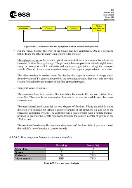
s Visual sights Controls Actuators Figure 4-113: Instrumentation and equipment used for manual final approach Motion control system units HMM Assessment Study Report: CDF-20(A) February 2004 page 378 of 422 • For the Visual Sights: The crew of the Soyuz uses two equipments. One is a periscope (BCK-4) and the other is a television system video monitor. The sight(periscope) is the primary optical instrument. It has a dual screen that allows the astronaut to view the target image. The periscope has two positions: attitude sight( aimed along the transport vehicle –Y-axis) and approach sight (aimed along the transport vehicle –X-axis). A reduced-scale colour image of the target is projected onto the screen. The video monitor is another mean for viewing the target. It receives its image signal from the external TV camera mounted on the habitation module. The crew only uses this system for qualitative assessment of the final approach process. • Transport Vehicle Controls. The astronauts have two controls. One translation hand controller and one rotation hand controller. The controls are mounted on brackets in the descent module near the center astronaut seat. The translational hand controller has two degrees of freedom. Tilting the stick in either direction will translate the vehicle’s centre of gravity in the directions ±Y and ±Z of the spacecraft coordinate system. The controller has a toggle switch with a middle (neutral) position to generate the signals required to translate the vehicle’s center of gravity in the ±X direction. The rotational hand controller has three degreesrees of freedom. With it you can control the vehicle’s rate of rotation to control attitude. 4.5.2.6.2 Mass and power budgets (redundancy included) Mass (kg) Power (W) Stick (Two) 1.6 15 Screen 2 50 Periscope 30 TBD Video monitor TBD TBD Table 4-55: Mass and power budgets
s 4.5.3 Structures HMM Assessment Study Report: CDF-20(A) February 2004 page 379 of 422 4.5.3.1 Requirements and design drivers For the design of the Mars Ascent Vehicle the following set of general requirements were taken into account: • Compatibility with the vehicle launcher Energia induced mechanical loads. • Compatibility with Energia fairing envelope. • MAV centre of gravity must be low as possible. All structures module shall provide the mechanical support to ensure mission success. 4.5.3.2 Assumptions and trade-off The MAV centre of gravity is assumed to be at 1 m, with the referential at the bottom part of it. 4.5.3.3 Baseline design Due to the short time frame for this module, no detailed analysis was performed. The analysis performed for the THM was used as reference. 4.5.3.3.1 MAV shell The MAV consists of a cylinder with 2.2 m of total length and 2.8 m of diameter. For the MAV mass determination, the first analysis began with comparison with the values of the Soyuz capsule without the heat shield. But the necessary usable volume for the MAV is higher, so as second analysis, due to the shape similarity, it was compared with the Columbus laboratory. For the thickness the same value was chosen as for the laboratory – 4 mm and for the skin material the same aluminium alloy as for the Columbus laboratory – AL 2219. As preliminary analyses the stiffeners mass was assumed to be half of the skin mass. For strength of the MAV it was assumed to have a ring every 0.6 m. The aim of these rings is to give the necessary rigidity to the MAV. 4.5.3.3.2 MAV propulsion module The MAV Propulsion Module consists of two stages. Each stage has four tanks and four engines, around a central cylinder, which accommodates a passage tunnel between MAV and SHM. For each stage there is a plate that supports the tanks and then engines. These plates consist of sandwich panels. All panels will be aluminium alloy for the face sheet, with 5 mm thickness and the core 30 mm thickness. In Figure 4-114 is described the nomenclature used for the structural parts for both stages. Note: The MAV shape shown in Figure 4-114 shows not the last version.
- Page 327 and 328: s 4.3.9.3 Baseline design 4.3.9.3.1
- Page 329 and 330: s Bio-Lock Masses: Core Samples No.
- Page 331 and 332: s HMM Assessment Study Report: CDF-
- Page 333 and 334: s HMM Assessment Study Report: CDF-
- Page 335 and 336: s Figure 4-72: Entry Velocity (L) a
- Page 337 and 338: s HMM Assessment Study Report: CDF-
- Page 339 and 340: s HMM Assessment Study Report: CDF-
- Page 341 and 342: s HMM Assessment Study Report: CDF-
- Page 343 and 344: s 2 3.9 233 923.1 347 923 12.3 352
- Page 345 and 346: s Figure 4-85: Communications MEV/M
- Page 347 and 348: s HMM Assessment Study Report: CDF-
- Page 349 and 350: s 4.4.5.3.2 GNC equipment HMM Asses
- Page 351 and 352: s 4.4.5.4 Control laws generation H
- Page 353 and 354: s HMM Assessment Study Report: CDF-
- Page 355 and 356: s Finally, the Figure 4-97 shown th
- Page 357 and 358: s HMM Assessment Study Report: CDF-
- Page 359 and 360: s HMM Assessment Study Report: CDF-
- Page 361 and 362: s velocity (m/sec) altitude (km) 50
- Page 363 and 364: s 4.5 Mars Ascent Vehicle 4.5.1 Tra
- Page 365 and 366: s Term Value Unit Radius of equator
- Page 367 and 368: s 4.5.2.1 Requirements and design d
- Page 369 and 370: s HMM Assessment Study Report: CDF-
- Page 371 and 372: s HMM Assessment Study Report: CDF-
- Page 373 and 374: s Inclination (deg) 47.5 47 46.5 46
- Page 375 and 376: s HMM Assessment Study Report: CDF-
- Page 377: s HMM Assessment Study Report: CDF-
- Page 381 and 382: s HMM Assessment Study Report: CDF-
- Page 383 and 384: s 4.5.5 Thermal HMM Assessment Stud
- Page 385 and 386: s 4.5.5.3 Baseline thermal design H
- Page 387 and 388: s HMM Assessment Study Report: CDF-
- Page 389 and 390: s Crew Ingress/Egress Hatch: HMM As
- Page 391 and 392: s Element 3: Mars Ascent Vehicle HM
- Page 393 and 394: s 4.5.7.5 Budgets Characteristic Va
- Page 395 and 396: s PER DAY PER MISSION DRINKING WATE
- Page 397 and 398: s HMM Assessment Study Report: CDF-
- Page 399 and 400: s HMM Assessment Study Report: CDF-
- Page 401 and 402: s 5 OVERALL CONCLUSIONS HMM Assessm
- Page 403 and 404: s 6 APPENDIX A - MARTIAN SURFACE NU
- Page 405 and 406: s HMM Assessment Study Report: CDF-
- Page 407 and 408: s Figure 6-1: Example of buried rea
- Page 409 and 410: s HMM Assessment Study Report: CDF-
- Page 411 and 412: s 7 APPENDIX B - REFERENCES [RD1] C
- Page 413 and 414: s [RD26] IES2, Phase A0: Final Repo
- Page 415 and 416: s HMM Assessment Study Report: CDF-
- Page 417 and 418: s [RD85] Mars Transportation Enviro
- Page 419 and 420: s 8 APPENDIX C - ACRONYMS AAA Avion
- Page 421 and 422: s MLI Multi-Layer Insulation MMH Mo
s<br />
Visual sights Controls Actuators<br />
Figure 4-113: Instrumentation and equipment used for manual final approach<br />
Motion<br />
control system<br />
units<br />
HMM<br />
Assessment Study<br />
Report: CDF-20(A)<br />
February 2004<br />
page 378 of 422<br />
• For the Visual Sights: The crew of the Soyuz uses two equipments. One is a periscope<br />
(BCK-4) and the other is a television system video monitor.<br />
The sight(periscope) is the primary optical instrument. It has a dual screen that allows the<br />
astronaut to view the target image. The periscope has two positions: attitude sight( aimed<br />
along the transport vehicle –Y-axis) and approach sight (aimed along the transport<br />
vehicle –X-axis). A reduced-scale colour image of the target is projected onto the screen.<br />
The video monitor is another mean for viewing the target. It receives its image signal<br />
from the external TV camera mounted on the habitation module. The crew only uses this<br />
system for qualitative assessment of the final approach process.<br />
• Transport Vehicle Controls.<br />
The astronauts have two controls. One translation hand controller and one rotation hand<br />
controller. The controls are mounted on brackets in the descent module near the center<br />
astronaut seat.<br />
The translational hand controller has two degrees of freedom. Tilting the stick in either<br />
direction will translate the vehicle’s centre of gravity in the directions ±Y and ±Z of the<br />
spacecraft coordinate system. The controller has a toggle switch with a middle (neutral)<br />
position to generate the signals required to translate the vehicle’s center of gravity in the<br />
±X direction.<br />
The rotational hand controller has three degreesrees of freedom. With it you can control<br />
the vehicle’s rate of rotation to control attitude.<br />
4.5.2.6.2 Mass and power budgets (redundancy included)<br />
Mass (kg) Power (W)<br />
Stick (Two) 1.6 15<br />
Screen 2 50<br />
Periscope 30 TBD<br />
Video monitor TBD TBD<br />
Table 4-55: Mass and power budgets


