ESA Document - Emits - ESA
ESA Document - Emits - ESA ESA Document - Emits - ESA
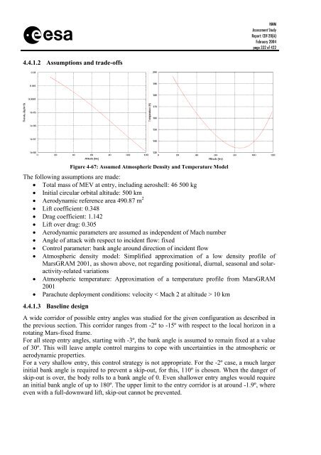
s 4.4.1.2 Assumptions and trade-offs HMM Assessment Study Report: CDF-20(A) February 2004 page 332 of 422 Figure 4-67: Assumed Atmospheric Density and Temperature Model The following assumptions are made: • Total mass of MEV at entry, including aeroshell: 46 500 kg • Initial circular orbital altitude: 500 km • Aerodynamic reference area 490.87 m 2 • Lift coefficient: 0.348 • Drag coefficient: 1.142 • Lift over drag: 0.305 • Aerodynamic parameters are assumed as independent of Mach number • Angle of attack with respect to incident flow: fixed • Control parameter: bank angle around direction of incident flow • Atmospheric density model: Simplified approximation of a low density profile of MarsGRAM 2001, as shown above, not regarding positional, diurnal, seasonal and solaractivity-related variations • Atmospheric temperature: Approximation of a temperature profile from MarsGRAM 2001 • Parachute deployment conditions: velocity < Mach 2 at altitude > 10 km 4.4.1.3 Baseline design A wide corridor of possible entry angles was studied for the given configuration as described in the previous section. This corridor ranges from -2º to -15º with respect to the local horizon in a rotating Mars-fixed frame. For all steep entry angles, starting with -3º, the bank angle is assumed to remain fixed at a value of 30º. This will leave ample control margins to cope with uncertainties in the atmospheric or aerodynamic properties. For a very shallow entry, this control strategy is not appropriate. For the -2º case, a much larger initial bank angle is required to prevent a skip-out, for this, 110º is chosen. When the danger of skip-out is over, the body rolls to a bank angle of 0. Even shallower entry angles would require an initial bank angle of up to 180º. The upper limit to the entry corridor is at around -1.9º, where even with a full-downward lift, skip-out cannot be prevented.
s HMM Assessment Study Report: CDF-20(A) February 2004 page 333 of 422 Figure 4-68 shows the altitude profile for seven regarded entry angles in the specified range from 2º-15º below the local horizon. The following sets of diagrams show the comparative evolution of Mach number, dynamic pressure and g-load. Figure 4-68: Altitude over Time for Seven Regarded Cases Figure 4-69: Mach Number over Time (L) and Altitude (R) for Regarded Cases
- Page 281 and 282: s Figure 4-28: Mars albedo (L), ars
- Page 283 and 284: s HMM Assessment Study Report: CDF-
- Page 285 and 286: s sun flux (W/m2) 450 400 350 300 2
- Page 287 and 288: s HMM Assessment Study Report: CDF-
- Page 289 and 290: s Insulation structure (external) F
- Page 291 and 292: s cryocooler heat lift [W] cryocool
- Page 293 and 294: s HMM Assessment Study Report: CDF-
- Page 295 and 296: s HMM Assessment Study Report: CDF-
- Page 297 and 298: s • a duty cycle value (duration
- Page 299 and 300: s Figure 4-48: MAV Power Inputs HMM
- Page 301 and 302: s HMM Assessment Study Report: CDF-
- Page 303 and 304: s 4.3.5.4.2 Power storage HMM Asses
- Page 305 and 306: s Figure 4-52: Regenerative Fuel Ce
- Page 307 and 308: s Figure 4-54: Solar irradiance on
- Page 309 and 310: s 450.00 400.00 350.00 300.00 250.0
- Page 311 and 312: s 4.3.6.1 Budgets HMM Assessment St
- Page 313 and 314: s HMM Assessment Study Report: CDF-
- Page 315 and 316: s HMM Assessment Study Report: CDF-
- Page 317 and 318: s HMM Assessment Study Report: CDF-
- Page 319 and 320: s HMM Assessment Study Report: CDF-
- Page 321 and 322: s HMM Assessment Study Report: CDF-
- Page 323 and 324: s Surface Surface Container MAV Con
- Page 325 and 326: s HMM Assessment Study Report: CDF-
- Page 327 and 328: s 4.3.9.3 Baseline design 4.3.9.3.1
- Page 329 and 330: s Bio-Lock Masses: Core Samples No.
- Page 331: s HMM Assessment Study Report: CDF-
- Page 335 and 336: s Figure 4-72: Entry Velocity (L) a
- Page 337 and 338: s HMM Assessment Study Report: CDF-
- Page 339 and 340: s HMM Assessment Study Report: CDF-
- Page 341 and 342: s HMM Assessment Study Report: CDF-
- Page 343 and 344: s 2 3.9 233 923.1 347 923 12.3 352
- Page 345 and 346: s Figure 4-85: Communications MEV/M
- Page 347 and 348: s HMM Assessment Study Report: CDF-
- Page 349 and 350: s 4.4.5.3.2 GNC equipment HMM Asses
- Page 351 and 352: s 4.4.5.4 Control laws generation H
- Page 353 and 354: s HMM Assessment Study Report: CDF-
- Page 355 and 356: s Finally, the Figure 4-97 shown th
- Page 357 and 358: s HMM Assessment Study Report: CDF-
- Page 359 and 360: s HMM Assessment Study Report: CDF-
- Page 361 and 362: s velocity (m/sec) altitude (km) 50
- Page 363 and 364: s 4.5 Mars Ascent Vehicle 4.5.1 Tra
- Page 365 and 366: s Term Value Unit Radius of equator
- Page 367 and 368: s 4.5.2.1 Requirements and design d
- Page 369 and 370: s HMM Assessment Study Report: CDF-
- Page 371 and 372: s HMM Assessment Study Report: CDF-
- Page 373 and 374: s Inclination (deg) 47.5 47 46.5 46
- Page 375 and 376: s HMM Assessment Study Report: CDF-
- Page 377 and 378: s HMM Assessment Study Report: CDF-
- Page 379 and 380: s 4.5.3 Structures HMM Assessment S
- Page 381 and 382: s HMM Assessment Study Report: CDF-
s<br />
4.4.1.2 Assumptions and trade-offs<br />
HMM<br />
Assessment Study<br />
Report: CDF-20(A)<br />
February 2004<br />
page 332 of 422<br />
Figure 4-67: Assumed Atmospheric Density and Temperature Model<br />
The following assumptions are made:<br />
• Total mass of MEV at entry, including aeroshell: 46 500 kg<br />
• Initial circular orbital altitude: 500 km<br />
• Aerodynamic reference area 490.87 m 2<br />
• Lift coefficient: 0.348<br />
• Drag coefficient: 1.142<br />
• Lift over drag: 0.305<br />
• Aerodynamic parameters are assumed as independent of Mach number<br />
• Angle of attack with respect to incident flow: fixed<br />
• Control parameter: bank angle around direction of incident flow<br />
• Atmospheric density model: Simplified approximation of a low density profile of<br />
MarsGRAM 2001, as shown above, not regarding positional, diurnal, seasonal and solaractivity-related<br />
variations<br />
• Atmospheric temperature: Approximation of a temperature profile from MarsGRAM<br />
2001<br />
• Parachute deployment conditions: velocity < Mach 2 at altitude > 10 km<br />
4.4.1.3 Baseline design<br />
A wide corridor of possible entry angles was studied for the given configuration as described in<br />
the previous section. This corridor ranges from -2º to -15º with respect to the local horizon in a<br />
rotating Mars-fixed frame.<br />
For all steep entry angles, starting with -3º, the bank angle is assumed to remain fixed at a value<br />
of 30º. This will leave ample control margins to cope with uncertainties in the atmospheric or<br />
aerodynamic properties.<br />
For a very shallow entry, this control strategy is not appropriate. For the -2º case, a much larger<br />
initial bank angle is required to prevent a skip-out, for this, 110º is chosen. When the danger of<br />
skip-out is over, the body rolls to a bank angle of 0. Even shallower entry angles would require<br />
an initial bank angle of up to 180º. The upper limit to the entry corridor is at around -1.9º, where<br />
even with a full-downward lift, skip-out cannot be prevented.


