- Page 1 and 2:
s HMM Assessment Study Report: CDF-
- Page 3 and 4:
s STUDY TEAM HMM Assessment Study R
- Page 5 and 6:
s T A B L E O F C O N T E N T S HMM
- Page 7 and 8:
s HMM Assessment Study Report: CDF-
- Page 9 and 10:
s L I S T O F F I G U R E S HMM Ass
- Page 11 and 12:
s HMM Assessment Study Report: CDF-
- Page 13 and 14:
s HMM Assessment Study Report: CDF-
- Page 15 and 16:
s L I S T O F T A B L E S HMM Asses
- Page 17 and 18:
s HMM Assessment Study Report: CDF-
- Page 19 and 20:
s 1 INTRODUCTION 1.1 Background HMM
- Page 21 and 22:
s 2 GENERAL ARCHITECTURE 2.1 Study
- Page 23 and 24:
s HMM Assessment Study Report: CDF-
- Page 25 and 26:
s 2.2.4.2 Accelerations HMM Assessm
- Page 27 and 28:
s 2.2.4.4 Temperature and relative
- Page 29 and 30:
s HMM Assessment Study Report: CDF-
- Page 31 and 32:
s HMM Assessment Study Report: CDF-
- Page 33 and 34:
s Figure 2-10: Trajectory Overview
- Page 35 and 36:
s 2.4.3.5 TEI and planetary protect
- Page 37 and 38:
s HMM Assessment Study Report: CDF-
- Page 39 and 40:
s HMM Assessment Study Report: CDF-
- Page 41 and 42:
s HMM Assessment Study Report: CDF-
- Page 43 and 44:
s HMM Assessment Study Report: CDF-
- Page 45 and 46:
s Mars Excursion Vehicle Transfer H
- Page 47 and 48:
s 2.7.5.1 Mission elements dry mass
- Page 49 and 50:
s 2.7.5.8 MEV release The MEV is re
- Page 51 and 52:
s Total mission time (days) 1200 10
- Page 53 and 54:
s HMM Assessment Study Report: CDF-
- Page 55 and 56:
s HMM Assessment Study Report: CDF-
- Page 57 and 58:
s stack 9 Propellant mass of the ne
- Page 59 and 60:
s HMM Assessment Study Report: CDF-
- Page 61 and 62:
s HMM Assessment Study Report: CDF-
- Page 63 and 64:
s HMM Assessment Study Report: CDF-
- Page 65 and 66:
s The core supporting structure has
- Page 67 and 68:
s 2.7.7.1.3 Mars excursion module S
- Page 69 and 70:
s 2.7.7.1.4 Earth return capsule HM
- Page 71 and 72:
s Mission Phase Description Event s
- Page 73 and 74:
s Mission Phase Description Event s
- Page 75 and 76:
s 2.7.10 Mission performance Table
- Page 77 and 78:
s Days on Martian surface 450 400 3
- Page 79 and 80:
s HMM Assessment Study Report: CDF-
- Page 81 and 82:
s HMM Assessment Study Report: CDF-
- Page 83 and 84:
s Maximum manoeuvre duration 6 mont
- Page 85 and 86:
s % of loss from baseline 20 18 16
- Page 87 and 88:
s 2.7.15 Sensitivity analysis HMM A
- Page 89 and 90:
s 2.7.15.4 Influence of the mass of
- Page 91 and 92:
s HMM Assessment Study Report: CDF-
- Page 93 and 94:
s Parameters used: • No Shuttle
- Page 95 and 96:
s 2.8.3.3 Launch 3- Front node Figu
- Page 97 and 98:
s HMM Assessment Study Report: CDF-
- Page 99 and 100:
s HMM Assessment Study Report: CDF-
- Page 101 and 102:
s HMM Assessment Study Report: CDF-
- Page 103 and 104:
s HMM Assessment Study Report: CDF-
- Page 105 and 106:
s HMM Assessment Study Report: CDF-
- Page 107 and 108:
s HMM Assessment Study Report: CDF-
- Page 109 and 110:
s 2.10.1.4 Communications HMM Asses
- Page 111 and 112:
s HMM Assessment Study Report: CDF-
- Page 113 and 114:
s 2.10.2.2.2 LEO assembly HMM Asses
- Page 115 and 116:
s HMM Assessment Study Report: CDF-
- Page 117 and 118:
s Basic RF link Four 70-m Ka-band s
- Page 119 and 120:
s HMM Assessment Study Report: CDF-
- Page 121 and 122:
s HMM Assessment Study Report: CDF-
- Page 123 and 124:
s HMM Assessment Study Report: CDF-
- Page 125 and 126:
s 3 TRANSFER VEHICLE 3.1 Systems…
- Page 127 and 128:
s Operational Requirements It shall
- Page 129 and 130:
s Trans Mars Injection Module Mars
- Page 131 and 132:
s Figure 3-2: Parallel configuratio
- Page 133 and 134:
s Figure 3-6: Global dimensions com
- Page 135 and 136:
s Front Node 3.2.3.1.3 EVA systems
- Page 137 and 138:
s Trans Mars Injection (three stage
- Page 139 and 140:
s Figure 3-16: Recommendations for
- Page 141 and 142:
s Factors to be considered Impacts
- Page 143 and 144:
s HMM Assessment Study Report: CDF-
- Page 145 and 146:
s HMM Assessment Study Report: CDF-
- Page 147 and 148:
s HMM Assessment Study Report: CDF-
- Page 149 and 150:
s Figure 3-24: Baseline design back
- Page 151 and 152:
s Figure 3-26: Baseline design priv
- Page 153 and 154:
s Module part 3............= 0 m 3
- Page 155 and 156:
s 3.3.2.1 Requirements and design d
- Page 157 and 158:
s HMM Assessment Study Report: CDF-
- Page 159 and 160:
s HMM Assessment Study Report: CDF-
- Page 161 and 162:
s HMM Assessment Study Report: CDF-
- Page 163 and 164:
s HMM Assessment Study Report: CDF-
- Page 165 and 166:
s HMM Assessment Study Report: CDF-
- Page 167 and 168:
s 3.3.3.1 Requirements and design d
- Page 169 and 170:
s HMM Assessment Study Report: CDF-
- Page 171 and 172:
s HMM Assessment Study Report: CDF-
- Page 173 and 174:
s HMM Assessment Study Report: CDF-
- Page 175 and 176:
s HMM Assessment Study Report: CDF-
- Page 177 and 178:
s flux [W/m2] 250 200 150 100 50 0
- Page 179 and 180:
s Figure 3-38: Power required to ma
- Page 181 and 182:
s HMM Assessment Study Report: CDF-
- Page 183 and 184:
s HMM Assessment Study Report: CDF-
- Page 185 and 186:
s 3.3.4.3 Assumptions and trade-off
- Page 187 and 188:
s 3.3.4.3.3 Power conditioning and
- Page 189 and 190:
s 3.3.5 AOCS HMM Assessment Study R
- Page 191 and 192:
s HMM Assessment Study Report: CDF-
- Page 193 and 194:
s Configuration Length (m) Total ma
- Page 195 and 196:
s 3.3.5.5 ACS for TMI 1 st HMM Asse
- Page 197 and 198:
s HMM Assessment Study Report: CDF-
- Page 199 and 200:
s HMM Assessment Study Report: CDF-
- Page 201 and 202:
s HMM Assessment Study Report: CDF-
- Page 203 and 204:
s HMM Assessment Study Report: CDF-
- Page 205 and 206:
s 3.3.6.2 Baseline design HMM Asses
- Page 207 and 208:
s HMM Assessment Study Report: CDF-
- Page 209 and 210:
s 5 Reduce 2dB pointing precision t
- Page 211 and 212:
s 70-m antenna 70-m antenna 3.3.7.5
- Page 213 and 214:
s Angular separation SEM > 10º SEM
- Page 215 and 216:
s Figure 3-63: Communications MEV/M
- Page 217 and 218:
s HMM Assessment Study Report: CDF-
- Page 219 and 220:
s HMM Assessment Study Report: CDF-
- Page 221 and 222:
s HMM Assessment Study Report: CDF-
- Page 223 and 224:
s HMM Assessment Study Report: CDF-
- Page 225 and 226:
s Element 1: Transfer Habitation Mo
- Page 227 and 228:
s HMM Assessment Study Report: CDF-
- Page 229 and 230:
s Radiation Shielding Shielding Req
- Page 231 and 232:
s HMM Assessment Study Report: CDF-
- Page 233 and 234:
s The propulsion system and its cha
- Page 235 and 236:
s HMM Assessment Study Report: CDF-
- Page 237 and 238:
s Item Nr. Mass [kg] Margin [%] Mas
- Page 239 and 240:
s HMM Assessment Study Report: CDF-
- Page 241 and 242:
s HMM Assessment Study Report: CDF-
- Page 243 and 244:
s HMM Assessment Study Report: CDF-
- Page 245 and 246:
s HMM Assessment Study Report: CDF-
- Page 247 and 248:
s 3.4.4 Mechanisms HMM Assessment S
- Page 249 and 250:
s 4 MARS EXCURSION VEHICLE 4.1 Syst
- Page 251 and 252:
s HMM Assessment Study Report: CDF-
- Page 253 and 254:
s Figure 4-2: Option 2: Vertical co
- Page 255 and 256:
s HMM Assessment Study Report: CDF-
- Page 257 and 258:
s 4.3 Surface habitation module Fig
- Page 259 and 260: s Figure 4-11: Section through the
- Page 261 and 262: s HMM Assessment Study Report: CDF-
- Page 263 and 264: s 4.3.1.5 Baseline design HMM Asses
- Page 265 and 266: s HMM Assessment Study Report: CDF-
- Page 267 and 268: s 4.3.1.5.3 Top level Figure 4-20:
- Page 269 and 270: s 4.3.2.3 Baseline design HMM Asses
- Page 271 and 272: s Schedule in hours for the most ac
- Page 273 and 274: s 4.3.3.6 Waste production HMM Asse
- Page 275 and 276: s Figure 4-26: Total pressure vs. O
- Page 277 and 278: s ECLS system mass: Figure 4-27: Ma
- Page 279 and 280: s HMM Assessment Study Report: CDF-
- Page 281 and 282: s Figure 4-28: Mars albedo (L), ars
- Page 283 and 284: s HMM Assessment Study Report: CDF-
- Page 285 and 286: s sun flux (W/m2) 450 400 350 300 2
- Page 287 and 288: s HMM Assessment Study Report: CDF-
- Page 289 and 290: s Insulation structure (external) F
- Page 291 and 292: s cryocooler heat lift [W] cryocool
- Page 293 and 294: s HMM Assessment Study Report: CDF-
- Page 295 and 296: s HMM Assessment Study Report: CDF-
- Page 297 and 298: s • a duty cycle value (duration
- Page 299 and 300: s Figure 4-48: MAV Power Inputs HMM
- Page 301 and 302: s HMM Assessment Study Report: CDF-
- Page 303 and 304: s 4.3.5.4.2 Power storage HMM Asses
- Page 305 and 306: s Figure 4-52: Regenerative Fuel Ce
- Page 307 and 308: s Figure 4-54: Solar irradiance on
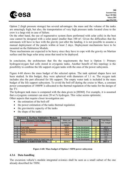
- Page 309: s 450.00 400.00 350.00 300.00 250.0
- Page 313 and 314: s HMM Assessment Study Report: CDF-
- Page 315 and 316: s HMM Assessment Study Report: CDF-
- Page 317 and 318: s HMM Assessment Study Report: CDF-
- Page 319 and 320: s HMM Assessment Study Report: CDF-
- Page 321 and 322: s HMM Assessment Study Report: CDF-
- Page 323 and 324: s Surface Surface Container MAV Con
- Page 325 and 326: s HMM Assessment Study Report: CDF-
- Page 327 and 328: s 4.3.9.3 Baseline design 4.3.9.3.1
- Page 329 and 330: s Bio-Lock Masses: Core Samples No.
- Page 331 and 332: s HMM Assessment Study Report: CDF-
- Page 333 and 334: s HMM Assessment Study Report: CDF-
- Page 335 and 336: s Figure 4-72: Entry Velocity (L) a
- Page 337 and 338: s HMM Assessment Study Report: CDF-
- Page 339 and 340: s HMM Assessment Study Report: CDF-
- Page 341 and 342: s HMM Assessment Study Report: CDF-
- Page 343 and 344: s 2 3.9 233 923.1 347 923 12.3 352
- Page 345 and 346: s Figure 4-85: Communications MEV/M
- Page 347 and 348: s HMM Assessment Study Report: CDF-
- Page 349 and 350: s 4.4.5.3.2 GNC equipment HMM Asses
- Page 351 and 352: s 4.4.5.4 Control laws generation H
- Page 353 and 354: s HMM Assessment Study Report: CDF-
- Page 355 and 356: s Finally, the Figure 4-97 shown th
- Page 357 and 358: s HMM Assessment Study Report: CDF-
- Page 359 and 360: s HMM Assessment Study Report: CDF-
- Page 361 and 362:
s velocity (m/sec) altitude (km) 50
- Page 363 and 364:
s 4.5 Mars Ascent Vehicle 4.5.1 Tra
- Page 365 and 366:
s Term Value Unit Radius of equator
- Page 367 and 368:
s 4.5.2.1 Requirements and design d
- Page 369 and 370:
s HMM Assessment Study Report: CDF-
- Page 371 and 372:
s HMM Assessment Study Report: CDF-
- Page 373 and 374:
s Inclination (deg) 47.5 47 46.5 46
- Page 375 and 376:
s HMM Assessment Study Report: CDF-
- Page 377 and 378:
s HMM Assessment Study Report: CDF-
- Page 379 and 380:
s 4.5.3 Structures HMM Assessment S
- Page 381 and 382:
s HMM Assessment Study Report: CDF-
- Page 383 and 384:
s 4.5.5 Thermal HMM Assessment Stud
- Page 385 and 386:
s 4.5.5.3 Baseline thermal design H
- Page 387 and 388:
s HMM Assessment Study Report: CDF-
- Page 389 and 390:
s Crew Ingress/Egress Hatch: HMM As
- Page 391 and 392:
s Element 3: Mars Ascent Vehicle HM
- Page 393 and 394:
s 4.5.7.5 Budgets Characteristic Va
- Page 395 and 396:
s PER DAY PER MISSION DRINKING WATE
- Page 397 and 398:
s HMM Assessment Study Report: CDF-
- Page 399 and 400:
s HMM Assessment Study Report: CDF-
- Page 401 and 402:
s 5 OVERALL CONCLUSIONS HMM Assessm
- Page 403 and 404:
s 6 APPENDIX A - MARTIAN SURFACE NU
- Page 405 and 406:
s HMM Assessment Study Report: CDF-
- Page 407 and 408:
s Figure 6-1: Example of buried rea
- Page 409 and 410:
s HMM Assessment Study Report: CDF-
- Page 411 and 412:
s 7 APPENDIX B - REFERENCES [RD1] C
- Page 413 and 414:
s [RD26] IES2, Phase A0: Final Repo
- Page 415 and 416:
s HMM Assessment Study Report: CDF-
- Page 417 and 418:
s [RD85] Mars Transportation Enviro
- Page 419 and 420:
s 8 APPENDIX C - ACRONYMS AAA Avion
- Page 421 and 422:
s MLI Multi-Layer Insulation MMH Mo


