ESA Document - Emits - ESA
ESA Document - Emits - ESA ESA Document - Emits - ESA
s HMM Assessment Study Report: CDF-20(A) February 2004 page 296 of 422 Figure 4-45: MEV Modes The MEV power subsystem has to cope with three different types of mission requirements: • during the descent: power needs to be supplied in a short time with some peak power constraint (pyros…) • during the surface operations: important level of power needs to be supplied for a long duration with possibility to generate power • during the launch, the parking orbits and the rendezvous: power needs to be supplied for a few days with a possibility to store energy during the sunlight, to have enough energy available for the eclipses and non-Sun pointed phases. Since the power system designed for the surface operations is able to cope with high power level during periods of 14 hours, it can also cover the energy requirements for the descent phase. Therefore, it has been chosen in this study not to develop a specific power subsystem for the descent phase. Nevertheless, a dedicated DM power subsystem is not excluded given that its mass would be negligible compared to the total MEV mass. On the MAV’s side, the mass is an important mission driver. Consequently, the implementation of the huge power subsystem required for the surface operation inside the MAV has been rejected. However, such a design would be possible in some particular cases for example when using fuel cells by keeping the useless and empty reactant tanks outside of the MAV. The MEV power system is composed of: • one power system inside the SHM which is also used by the DM • one power system located in the MAV for supplying the power after the launch from Mars. These two subsystems are completely independent, except that the MAV power subsystem can be charged by the SHM power system to the launch. 4.3.5.2.2 Power requirements In this study, the power requirements have been computed unit per unit and mode per mode (DM: Figure 4-46, SHM: Figure 4-47, MAV: Figure 4-48). Each unit power profile is defined by three values: • a peak power • a standby power
s • a duty cycle value (duration of the peak power compared to the total duration) HMM Assessment Study Report: CDF-20(A) February 2004 page 297 of 422 For every mode, the peak and standby values have been added to obtain the values at system level. An equivalent duty cycle has also been computed to keep the same level of energy (See Figure 4-49). Figure 4-46: DM power inputs
- Page 245 and 246: s HMM Assessment Study Report: CDF-
- Page 247 and 248: s 3.4.4 Mechanisms HMM Assessment S
- Page 249 and 250: s 4 MARS EXCURSION VEHICLE 4.1 Syst
- Page 251 and 252: s HMM Assessment Study Report: CDF-
- Page 253 and 254: s Figure 4-2: Option 2: Vertical co
- Page 255 and 256: s HMM Assessment Study Report: CDF-
- Page 257 and 258: s 4.3 Surface habitation module Fig
- Page 259 and 260: s Figure 4-11: Section through the
- Page 261 and 262: s HMM Assessment Study Report: CDF-
- Page 263 and 264: s 4.3.1.5 Baseline design HMM Asses
- Page 265 and 266: s HMM Assessment Study Report: CDF-
- Page 267 and 268: s 4.3.1.5.3 Top level Figure 4-20:
- Page 269 and 270: s 4.3.2.3 Baseline design HMM Asses
- Page 271 and 272: s Schedule in hours for the most ac
- Page 273 and 274: s 4.3.3.6 Waste production HMM Asse
- Page 275 and 276: s Figure 4-26: Total pressure vs. O
- Page 277 and 278: s ECLS system mass: Figure 4-27: Ma
- Page 279 and 280: s HMM Assessment Study Report: CDF-
- Page 281 and 282: s Figure 4-28: Mars albedo (L), ars
- Page 283 and 284: s HMM Assessment Study Report: CDF-
- Page 285 and 286: s sun flux (W/m2) 450 400 350 300 2
- Page 287 and 288: s HMM Assessment Study Report: CDF-
- Page 289 and 290: s Insulation structure (external) F
- Page 291 and 292: s cryocooler heat lift [W] cryocool
- Page 293 and 294: s HMM Assessment Study Report: CDF-
- Page 295: s HMM Assessment Study Report: CDF-
- Page 299 and 300: s Figure 4-48: MAV Power Inputs HMM
- Page 301 and 302: s HMM Assessment Study Report: CDF-
- Page 303 and 304: s 4.3.5.4.2 Power storage HMM Asses
- Page 305 and 306: s Figure 4-52: Regenerative Fuel Ce
- Page 307 and 308: s Figure 4-54: Solar irradiance on
- Page 309 and 310: s 450.00 400.00 350.00 300.00 250.0
- Page 311 and 312: s 4.3.6.1 Budgets HMM Assessment St
- Page 313 and 314: s HMM Assessment Study Report: CDF-
- Page 315 and 316: s HMM Assessment Study Report: CDF-
- Page 317 and 318: s HMM Assessment Study Report: CDF-
- Page 319 and 320: s HMM Assessment Study Report: CDF-
- Page 321 and 322: s HMM Assessment Study Report: CDF-
- Page 323 and 324: s Surface Surface Container MAV Con
- Page 325 and 326: s HMM Assessment Study Report: CDF-
- Page 327 and 328: s 4.3.9.3 Baseline design 4.3.9.3.1
- Page 329 and 330: s Bio-Lock Masses: Core Samples No.
- Page 331 and 332: s HMM Assessment Study Report: CDF-
- Page 333 and 334: s HMM Assessment Study Report: CDF-
- Page 335 and 336: s Figure 4-72: Entry Velocity (L) a
- Page 337 and 338: s HMM Assessment Study Report: CDF-
- Page 339 and 340: s HMM Assessment Study Report: CDF-
- Page 341 and 342: s HMM Assessment Study Report: CDF-
- Page 343 and 344: s 2 3.9 233 923.1 347 923 12.3 352
- Page 345 and 346: s Figure 4-85: Communications MEV/M
s<br />
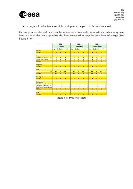
• a duty cycle value (duration of the peak power compared to the total duration)<br />
HMM<br />
Assessment Study<br />
Report: CDF-20(A)<br />
February 2004<br />
page 297 of 422<br />
For every mode, the peak and standby values have been added to obtain the values at system<br />
level. An equivalent duty cycle has also been computed to keep the same level of energy (See<br />
Figure 4-49).<br />
Figure 4-46: DM power inputs


