ESA Document - Emits - ESA
ESA Document - Emits - ESA ESA Document - Emits - ESA
s Configuration Length (m) Total mass (tonnes) Total length (m) Comp CoG (m) Inertia total kg*m^2/1000 MEV 10 46 10 5.0 THM 19 65 29 13.5 ERC 0 15 29 15.3 22874 TEI 15 160 44 27.2 63444 MOI 0 100 44 31.5 84414 HMM Assessment Study Report: CDF-20(A) February 2004 page 192 of 422 Table 3-35: TEI and MOI dimensions The ACS functions shall be: • Attitude control while orbiting Mars • Manoeuvres • Rate dumping after MOI motor separation: 0.5 degrees/s dumped in 30 seconds (maximum attitude error 15 degrees) Again, the last one is the most demanding The maximum torque needed in this case is: 25 000 Nm If ACS is dislocated in the three points, the torque arms shall be: b1 = 21.5 m b2 = 2.5 m b3 = 12.5 m Considering 440N thrust at b1 and b2, a torque contribution of 440*(21.5+2.5) = 10500 Nm is given by the ACS of the habitation module. The additional thrusters to be located in b3 are: Thrust needed = 25000-10500/12.5 = 1160 N So a cluster of 2 Ariane-5 SCA thrusters (2x550=1100N) might be used here. 3.3.5.3 ACS for TMI 3 rd In this configuration four control points shall be actives: P1, P2, P3 and P4, as shown in Figure 3-49. P4 P3 EV Airlock A 1 P2 Habitation Module Figure 3-49: TMI 3 rd configuration P1
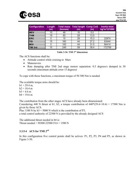
s Configuration Length (m) Total mass (tonnes) Total length (m) Comp CoG (m) Inertia total kg*m^2/1000 MEV 10 46 10 5.0 THM 19 65 29 13.5 ERC 0 15 29 15.3 22874 TEI 15 160 44 27.2 63444 MOI 0 100 44 31.5 84414 TMI 3rd 15 249 59 39.4 172759 HMM Assessment Study Report: CDF-20(A) February 2004 page 193 of 422 Table 3-36: TMI 3 rd dimensions The ACS functions shall be: • Attitude control while cruising to Mars • Manoeuvres • Rate dumping after TMI 2nd stage motors separation: 0.5 degrees/s dumped in 30 seconds (maximum attitude error 15 degrees) To cope with those functions, a maximum torque of 50 300 Nm is needed. The available torque arms should be: b1 = 29.4 m, b2 = 10.4 m b3 = 4.6 m b4 = 19.6 m The contribution from the other stages ACS have already been dimensioned: Considering 440 N thrust at b1, b2, a torque contribution of 440*(29.4+10.4) = 17500 Nm is given by those ACS. Plus 1100 N by b3 = 5000 N which is the contribution of P3, a total control authority of 22500 N is provided by the already designed ACS The additional thrust needed in b4 is: Thrust needed = 50300-22500/19.6 = 1500 N 3.3.5.4 ACS for TMI 2 nd In this configuration five control points shall be actives: P1, P2, P3, P4 and P5, as shown in Figure 3-50.
- Page 141 and 142: s Factors to be considered Impacts
- Page 143 and 144: s HMM Assessment Study Report: CDF-
- Page 145 and 146: s HMM Assessment Study Report: CDF-
- Page 147 and 148: s HMM Assessment Study Report: CDF-
- Page 149 and 150: s Figure 3-24: Baseline design back
- Page 151 and 152: s Figure 3-26: Baseline design priv
- Page 153 and 154: s Module part 3............= 0 m 3
- Page 155 and 156: s 3.3.2.1 Requirements and design d
- Page 157 and 158: s HMM Assessment Study Report: CDF-
- Page 159 and 160: s HMM Assessment Study Report: CDF-
- Page 161 and 162: s HMM Assessment Study Report: CDF-
- Page 163 and 164: s HMM Assessment Study Report: CDF-
- Page 165 and 166: s HMM Assessment Study Report: CDF-
- Page 167 and 168: s 3.3.3.1 Requirements and design d
- Page 169 and 170: s HMM Assessment Study Report: CDF-
- Page 171 and 172: s HMM Assessment Study Report: CDF-
- Page 173 and 174: s HMM Assessment Study Report: CDF-
- Page 175 and 176: s HMM Assessment Study Report: CDF-
- Page 177 and 178: s flux [W/m2] 250 200 150 100 50 0
- Page 179 and 180: s Figure 3-38: Power required to ma
- Page 181 and 182: s HMM Assessment Study Report: CDF-
- Page 183 and 184: s HMM Assessment Study Report: CDF-
- Page 185 and 186: s 3.3.4.3 Assumptions and trade-off
- Page 187 and 188: s 3.3.4.3.3 Power conditioning and
- Page 189 and 190: s 3.3.5 AOCS HMM Assessment Study R
- Page 191: s HMM Assessment Study Report: CDF-
- Page 195 and 196: s 3.3.5.5 ACS for TMI 1 st HMM Asse
- Page 197 and 198: s HMM Assessment Study Report: CDF-
- Page 199 and 200: s HMM Assessment Study Report: CDF-
- Page 201 and 202: s HMM Assessment Study Report: CDF-
- Page 203 and 204: s HMM Assessment Study Report: CDF-
- Page 205 and 206: s 3.3.6.2 Baseline design HMM Asses
- Page 207 and 208: s HMM Assessment Study Report: CDF-
- Page 209 and 210: s 5 Reduce 2dB pointing precision t
- Page 211 and 212: s 70-m antenna 70-m antenna 3.3.7.5
- Page 213 and 214: s Angular separation SEM > 10º SEM
- Page 215 and 216: s Figure 3-63: Communications MEV/M
- Page 217 and 218: s HMM Assessment Study Report: CDF-
- Page 219 and 220: s HMM Assessment Study Report: CDF-
- Page 221 and 222: s HMM Assessment Study Report: CDF-
- Page 223 and 224: s HMM Assessment Study Report: CDF-
- Page 225 and 226: s Element 1: Transfer Habitation Mo
- Page 227 and 228: s HMM Assessment Study Report: CDF-
- Page 229 and 230: s Radiation Shielding Shielding Req
- Page 231 and 232: s HMM Assessment Study Report: CDF-
- Page 233 and 234: s The propulsion system and its cha
- Page 235 and 236: s HMM Assessment Study Report: CDF-
- Page 237 and 238: s Item Nr. Mass [kg] Margin [%] Mas
- Page 239 and 240: s HMM Assessment Study Report: CDF-
- Page 241 and 242: s HMM Assessment Study Report: CDF-
s<br />
Configuration Length<br />
(m)<br />
Total mass<br />
(tonnes)<br />
Total length<br />
(m)<br />
Comp CoG<br />
(m)<br />
Inertia total<br />
kg*m^2/1000<br />
MEV 10 46 10 5.0<br />
THM 19 65 29 13.5<br />
ERC 0 15 29 15.3 22874<br />
TEI 15 160 44 27.2 63444<br />
MOI 0 100 44 31.5 84414<br />
TMI 3rd 15 249 59 39.4 172759<br />
HMM<br />
Assessment Study<br />
Report: CDF-20(A)<br />
February 2004<br />
page 193 of 422<br />
Table 3-36: TMI 3 rd dimensions<br />
The ACS functions shall be:<br />
• Attitude control while cruising to Mars<br />
• Manoeuvres<br />
• Rate dumping after TMI 2nd stage motors separation: 0.5 degrees/s dumped in 30<br />
seconds (maximum attitude error 15 degrees)<br />
To cope with those functions, a maximum torque of 50 300 Nm is needed.<br />
The available torque arms should be:<br />
b1 = 29.4 m,<br />
b2 = 10.4 m<br />
b3 = 4.6 m<br />
b4 = 19.6 m<br />
The contribution from the other stages ACS have already been dimensioned:<br />
Considering 440 N thrust at b1, b2, a torque contribution of 440*(29.4+10.4) = 17500 Nm is<br />
given by those ACS.<br />
Plus 1100 N by b3 = 5000 N which is the contribution of P3,<br />
a total control authority of 22500 N is provided by the already designed ACS<br />
The additional thrust needed in b4 is:<br />
Thrust needed = 50300-22500/19.6 = 1500 N<br />
3.3.5.4 ACS for TMI 2 nd<br />
In this configuration five control points shall be actives: P1, P2, P3, P4 and P5, as shown in<br />
Figure 3-50.


