ESA Document - Emits - ESA
ESA Document - Emits - ESA
ESA Document - Emits - ESA
- TAGS
- emits
- emits.esa.int

You also want an ePaper? Increase the reach of your titles
YUMPU automatically turns print PDFs into web optimized ePapers that Google loves.
s<br />
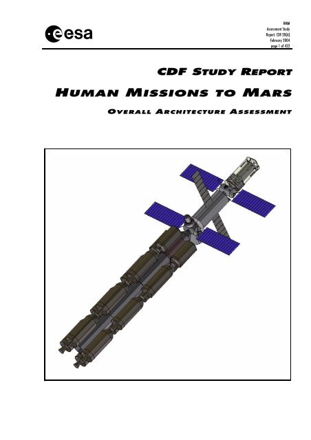
HMM<br />
Assessment Study<br />
Report: CDF-20(A)<br />
February 2004<br />
page 1 of 422<br />
CDF STUDY REPORT<br />
UMAN ISSIONS TO ARS<br />
O VERALL A RCHITECTURE A SSESSMENT
s<br />
FRONT COVER<br />
(The front cover shows schematic of the complete vehicle for a<br />
human mission to Mars)<br />
PROJECT<br />
Assessment Study<br />
Report: CDF-20(A)<br />
February 2004<br />
page 2 of 422
s<br />
STUDY TEAM<br />
HMM<br />
Assessment Study<br />
Report: CDF-20(A)<br />
February 2004<br />
page 3 of 422<br />
This Assessment Study was performed in the ESTEC Concurrent Design Facility (CDF) by the<br />
following interdisciplinary team:<br />
TEAM LEADER A. Santovincenzo, TOS-ACD<br />
SYSTEMS D. Escorial, TOS-ACD<br />
AEROTHERMO-<br />
DYNAMICS<br />
S. Durrant, TOS-MMM<br />
S. Bayon, TOS-ACD<br />
M. A. Larsen, TOS-ACD<br />
F. Mazoue, TOS-MPA<br />
J. Kirchner, MSM-MX<br />
MISSION ANALYSIS M. Khan, TOS-GA<br />
M. Landgraf, TOS-GA<br />
POWER S. Zimmermann, TOS-<br />
EPS<br />
COMMUNICATIONS J. V. Perello, TOS-ET PROGRAMMATICS M. Braghin, TOS-MTC<br />
CONFIGURATION R. Westenberg, TOS-MCS<br />
B. Imhof (Liquifer)<br />
PROPULSION N. Kutufa, TOS-MPE<br />
COST P. Ponzio, IMT-ICE RADIATION H. Evans, TOS_EMA<br />
DATA HANDLING G. Furano, TOS-ESD RISK/SAFETY P. Villar, TOS-QQD<br />
GNC G. Ortega, TOS-ESN<br />
M. Sallusti, TOS-ECN<br />
SIMULATION L. Dwedari, TOS-EMM<br />
GROUND SEGMENT R. Timm, TOS-OS STRUCTURES C. Cabaco, TOS-MCS<br />
LIFE SUPPORT A. Rodriguez, TOS-MCT THERMAL D. Schwaller, TOS-MCT<br />
HUMAN FACTORS B. Houdou, MSM-MC TRAJECTORIES A. Martinez, TOS-EMZ<br />
MECHANISMS S. Durrant, TOS-MMM<br />
Under the responsibility of:<br />
L. Bessone, <strong>ESA</strong>/EAC/MSM-AT, Study Manager<br />
D. Vennemann, <strong>ESA</strong>/ESTEC/MSM-MF, Study Manager<br />
Additional contribution by:<br />
B. Parkinson, L. Summerer, A. Cawthorne, K. Legner, R. Condessa, G. Kminek, M. Vasile, U.<br />
Thomas, P. Rodriguez<br />
Contribution to the editing and compilation of this report has been provided by:<br />
J. Taylor, TOS-ACD<br />
M. Kruk-Strzelecki, TOS-ACD
s<br />
Further information and/or additional copies of the report are available from:<br />
L. Bessone<br />
EAC/<strong>ESA</strong>/MSM-AT<br />
Linder Hoehe<br />
D-51147 Cologne<br />
Germany<br />
Tel: +(49)-2203 6001 340<br />
Fax: +(49)-2203 6001 302<br />
Loredana.Bessone@esa.int<br />
For further information on the Concurrent Design Facility please contact:<br />
M. Bandecchi<br />
<strong>ESA</strong>/ESTEC/TOS-ACD<br />
Postbus 299<br />
2200 AG Noordwijk<br />
The Netherlands<br />
Tel: +(31)-71-5653701<br />
Fax: +(31)-71-5656024<br />
Massimo.Bandecchi@esa.int<br />
PROJECT<br />
Assessment Study<br />
Report: CDF-20(A)<br />
February 2004<br />
page 4 of 422
s<br />
T A B L E O F C O N T E N T S<br />
HMM<br />
Assessment Study<br />
Report: CDF-20(A)<br />
February 2004<br />
page 5 of 422<br />
1 INTRODUCTION .................................................................................................... 19<br />
1.1 Background ................................................................................................................................19<br />
1.2 CDF study ..................................................................................................................................19<br />
1.3 <strong>Document</strong> structure....................................................................................................................19<br />
2 GENERAL ARCHITECTURE................................................................................. 21<br />
2.1 Study objectives.........................................................................................................................21<br />
2.2 Overall mission requirements and constraints...........................................................................22<br />
2.2.1 Mission Objectives.....................................................................................................................22<br />
2.2.2 Mission-general requirements ...................................................................................................23<br />
2.2.3 Safety requirements ..................................................................................................................23<br />
2.2.4 Physiology requirements: ..........................................................................................................23<br />
2.2.5 Planetary protection requirements ............................................................................................29<br />
2.2.6 Constraints ................................................................................................................................30<br />
2.3 Background ................................................................................................................................31<br />
2.4 Mission analysis.........................................................................................................................31<br />
2.4.1 Requirements and design drivers..............................................................................................31<br />
2.4.2 Assumptions and trade-offs.......................................................................................................32<br />
2.4.3 Baseline design .........................................................................................................................32<br />
2.4.4 Budgets .....................................................................................................................................35<br />
2.4.5 Options ......................................................................................................................................36<br />
2.5 Cruise and surface operations ...................................................................................................37<br />
2.5.1 Planetary protection ..................................................................................................................37<br />
2.5.2 Human surface operations on Mars ..........................................................................................38<br />
2.5.3 Conclusions...............................................................................................................................39<br />
2.6 Radiation environment ...............................................................................................................39<br />
2.6.1 Trapped particle belts................................................................................................................40<br />
2.6.2 Solar proton events ...................................................................................................................40<br />
2.6.3 Galactic cosmic rays .................................................................................................................40<br />
2.6.4 Requirements and design drivers..............................................................................................40<br />
2.6.5 Assumptions and trade-offs.......................................................................................................42<br />
2.6.6 Budgets .....................................................................................................................................43<br />
2.6.7 Conclusions...............................................................................................................................43<br />
2.7 Mission architecture ...................................................................................................................44<br />
2.7.1 Mission case..............................................................................................................................44<br />
2.7.2 Mission case basic architecture ................................................................................................44<br />
2.7.3 Key parameters .........................................................................................................................45<br />
2.7.4 Mission case architecture options .............................................................................................45<br />
2.7.5 Basic assumptions for trade-offs...............................................................................................46<br />
2.7.6 Trade-offs ..................................................................................................................................50<br />
2.7.7 Vehicle architecture...................................................................................................................62<br />
2.7.8 Launchers..................................................................................................................................69<br />
2.7.9 Mission phases..........................................................................................................................70<br />
2.7.10 Mission performance ....................................................................................................75<br />
2.7.11 Surface opportunities....................................................................................................75<br />
2.7.12 Abort Options................................................................................................................78<br />
2.7.13 Aerobraking ..................................................................................................................82<br />
2.7.14 Artificial gravity .............................................................................................................84<br />
2.7.15 Sensitivity analysis .......................................................................................................87<br />
2.8 In orbit assembly........................................................................................................................89<br />
2.8.1 Assumptions and trade-offs.......................................................................................................89<br />
2.8.2 Sensitivity analysis ....................................................................................................................92<br />
2.8.3 Baseline design .........................................................................................................................93<br />
2.8.4 Options ....................................................................................................................................100
s<br />
PROJECT<br />
Assessment Study<br />
Report: CDF-20(A)<br />
February 2004<br />
page 6 of 422<br />
2.9 Safety/risk assessment............................................................................................................ 101<br />
2.9.1 Mission-specific characteristics .............................................................................................. 101<br />
2.9.2 Definition of “safety and mission success” ............................................................................. 101<br />
2.9.3 Safety requirements:............................................................................................................... 101<br />
2.9.4 Mission factors/issues:............................................................................................................ 101<br />
2.9.5 Technical risk assessment scope........................................................................................... 102<br />
2.9.6 Abort possibilities.................................................................................................................... 102<br />
2.9.7 Risk acceptability .................................................................................................................... 103<br />
2.9.8 Risk assessment process example ........................................................................................ 105<br />
2.10 Ground segment and operations............................................................................................. 106<br />
2.10.1 Mission operations concept ....................................................................................... 106<br />
2.10.2 Ground segment concept........................................................................................... 111<br />
2.11 Simulation................................................................................................................................ 118<br />
2.11.1 Simulation results....................................................................................................... 118<br />
2.11.2 Simulation tool selection ............................................................................................ 119<br />
2.12 Programmatics ........................................................................................................................ 120<br />
2.12.1 Requirements and programmatic drivers................................................................... 120<br />
2.12.2 Assumptions and trade-offs ....................................................................................... 120<br />
2.12.3 Model philosophy and qualification............................................................................ 121<br />
2.12.4 Baseline operations ................................................................................................... 122<br />
2.12.5 Options....................................................................................................................... 123<br />
3 TRANSFER VEHICLE ......................................................................................... 125<br />
3.1 Systems……............................................................................................................................ 125<br />
3.1.1 System requirements.............................................................................................................. 125<br />
3.1.2 System design drivers ............................................................................................................ 127<br />
3.1.3 Mass budget ........................................................................................................................... 128<br />
3.2 Configuration ........................................................................................................................... 130<br />
3.2.1 Requirements and design drivers........................................................................................... 130<br />
3.2.2 Assumptions and trade-offs .................................................................................................... 130<br />
3.2.3 Baseline design....................................................................................................................... 132<br />
3.3 Transfer Habitation Module ..................................................................................................... 138<br />
3.3.1 Internal configuration .............................................................................................................. 138<br />
3.3.2 Environmental control and life support system....................................................................... 154<br />
3.3.3 Thermal................................................................................................................................... 166<br />
3.3.4 Power...................................................................................................................................... 182<br />
3.3.5 AOCS...................................................................................................................................... 189<br />
3.3.6 Data handling.......................................................................................................................... 196<br />
3.3.7 Communications ..................................................................................................................... 205<br />
3.3.8 Mechanisms............................................................................................................................ 217<br />
3.3.9 Structures................................................................................................................................ 226<br />
3.4 Propulsion module................................................................................................................... 230<br />
3.4.1 Propulsion ............................................................................................................................... 230<br />
3.4.2 Structures................................................................................................................................ 234<br />
3.4.3 Thermal................................................................................................................................... 238<br />
3.4.4 Mechanisms............................................................................................................................ 247<br />
4 MARS EXCURSION VEHICLE............................................................................ 249<br />
4.1 Systems……............................................................................................................................ 249<br />
4.1.1 System requirements.............................................................................................................. 249<br />
4.1.2 System design drivers ............................................................................................................ 250<br />
4.1.3 Mass budget ........................................................................................................................... 251<br />
4.2 Configuration ........................................................................................................................... 251<br />
4.2.1 Requirements and design drivers........................................................................................... 251<br />
4.2.2 Assumptions and trade-offs .................................................................................................... 252<br />
4.2.3 Baseline design....................................................................................................................... 253<br />
4.2.4 Surface habitation module ...................................................................................................... 254
s<br />
HMM<br />
Assessment Study<br />
Report: CDF-20(A)<br />
February 2004<br />
page 7 of 422<br />
4.2.5 Mars ascent vehicle.................................................................................................................256<br />
4.3 Surface habitation module .......................................................................................................257<br />
4.3.1 Internal configuration...............................................................................................................257<br />
4.3.2 Propulsion................................................................................................................................268<br />
4.3.3 Environmental control and life support system .......................................................................270<br />
4.3.4 Thermal ...................................................................................................................................279<br />
4.3.5 Power ......................................................................................................................................294<br />
4.3.6 Data handling ..........................................................................................................................310<br />
4.3.7 Communications......................................................................................................................311<br />
4.3.8 Mechanisms ............................................................................................................................316<br />
4.3.9 Sample handling......................................................................................................................319<br />
4.3.10 Structures ...................................................................................................................330<br />
4.4 Descent Module .......................................................................................................................331<br />
4.4.1 Entry Analysis..........................................................................................................................331<br />
4.4.2 Aerothermodynamics ..............................................................................................................336<br />
4.4.3 Structures ................................................................................................................................341<br />
4.4.4 Communications......................................................................................................................343<br />
4.4.5 GNC.........................................................................................................................................345<br />
4.4.6 Mechanisms ............................................................................................................................356<br />
4.4.7 Parachute design.....................................................................................................................359<br />
4.4.8 Propulsion................................................................................................................................362<br />
4.5 Mars Ascent Vehicle ................................................................................................................363<br />
4.5.1 Trajectories..............................................................................................................................363<br />
4.5.2 GNC and rendezvous & docking.............................................................................................366<br />
4.5.3 Structures ................................................................................................................................379<br />
4.5.4 Power ......................................................................................................................................380<br />
4.5.5 Thermal ...................................................................................................................................383<br />
4.5.6 Mechanisms ............................................................................................................................388<br />
4.5.7 Propulsion................................................................................................................................391<br />
4.5.8 Environmental control and life support system .......................................................................393<br />
4.5.9 Data handling ..........................................................................................................................398<br />
4.5.10 Communications.........................................................................................................398<br />
5 OVERALL CONCLUSIONS ................................................................................. 401<br />
5.1 Technology development.........................................................................................................402<br />
6 APPENDIX A - MARTIAN SURFACE NUCLEAR REACTOR............................. 403<br />
6.1 General parameters and initial assumptions ...........................................................................403<br />
6.2 Reactor type, mass and sizing aspects ...................................................................................403<br />
6.2.1 General parameters ................................................................................................................403<br />
6.2.2 Main differences to terrestrial systems....................................................................................403<br />
6.2.3 Approach .................................................................................................................................404<br />
6.3 Reactor power subsystems......................................................................................................404<br />
6.4 Radiation protection and shielding issues ...............................................................................406<br />
6.5 Reactor operation.....................................................................................................................407<br />
6.5.1 Pre-launch operations .............................................................................................................408<br />
6.5.2 Start-up....................................................................................................................................408<br />
6.5.3 Nominal operations .................................................................................................................408<br />
6.5.4 Emergency operations ............................................................................................................408<br />
7 APPENDIX B – REFERENCES ........................................................................... 411<br />
8 APPENDIX C - ACRONYMS................................................................................ 419
s<br />
PROJECT<br />
Assessment Study<br />
Report: CDF-20(A)<br />
February 2004<br />
page 8 of 422
s<br />
L I S T O F F I G U R E S<br />
HMM<br />
Assessment Study<br />
Report: CDF-20(A)<br />
February 2004<br />
page 9 of 422<br />
FIGURE 2-1: REQUIRED PRESSURISED VOLUME AS A FUNCTION OF THE MISSION DURATION (HISTORICAL DATA) ........24<br />
FIGURE 2-2: SURFACE AVAILABLE IN THE DIFFERENT EARTH SYSTEMS........................................................................24<br />
FIGURE 2-3: BODY AXES DIRECTIONS ..........................................................................................................................25<br />
FIGURE 2-4: MAXIMUM ALLOWABLE G-LOADS IN THE +GX DIRECTION.......................................................................25<br />
FIGURE 2-5: REQUIREMENTS FOR SUSTAINED G-LOADS ...............................................................................................26<br />
FIGURE 2-6: TOLERANCE TO SHORT-DURATION –GZ ACCELERATIONS.........................................................................26<br />
FIGURE 2-7: TEMPERATURE AND HUMIDITY LEVELS ...................................................................................................27<br />
FIGURE 2-8: ALLOWABLE CAREER RADIATION LEVELS BASED ON GENDER AND AGE OF THE CREW............................28<br />
FIGURE 2-9: ASSUMED RECONDITIONING TIME TO MARTIAN GRAVITY ENVIRONMENT................................................28<br />
FIGURE 2-10: TRAJECTORY OVERVIEW FOR MISSION 2033 .........................................................................................33<br />
FIGURE 2-11: GEOMETRY FOR EARTH-MARS TRANSFER .............................................................................................33<br />
FIGURE 2-12: GEOMETRY DURING MARS PHASE.........................................................................................................34<br />
FIGURE 2-13: GEOMETRY DURING MARS-EARTH TRANSFER ......................................................................................34<br />
FIGURE 2-14: EARTH RETURN TRAJECTORY STRATEGY ..............................................................................................35<br />
FIGURE 2-15: DISTRIBUTION OF THE EVENT DURATION WHERE THE 10 MEV FLUX EXCEEDS 2 PROTONS/CM 2 /S/STER.41<br />
FIGURE 2-16: GCR DOSE EQUIVALENT (SV/YEAR) AS A FUNCTION OF SHIELDING THICKNESS.....................................42<br />
FIGURE 2-17: MISSION ELEMENTS FOR A HUMAN MISSION TO MARS ...........................................................................45<br />
FIGURE 2-18: ∆V REQUIRED FOR THE DIFFERENT SOLUTIONS ......................................................................................50<br />
FIGURE 2-19: MISSION DURATION FOR THE DIFFERENT SOLUTIONS .............................................................................51<br />
FIGURE 2-20: TOTAL MISSION DURATION, TRIP DURATION AND STAY TIME AROUND MARS AND RATIO ......................52<br />
FIGURE 2-21: ENERGY REQUIREMENTS ........................................................................................................................53<br />
FIGURE 2-22: ENTRY VELOCITY AT EARTH ..................................................................................................................54<br />
FIGURE 2-23: BOIL-OFF PROCESS .................................................................................................................................56<br />
FIGURE 2-24: BOIL-OFF EFFECTS AND ∆V CAPABILITY LOSS .......................................................................................57<br />
FIGURE 2-25: EFFECT OF DIFFERENT PARAMETERS ON THE BOIL-OFF (11 STACKS WITH A PAYLOAD OF 470 TONNES).57<br />
FIGURE 2-26: NUMBER OF STACKS REQUIRED AS A FUNCTION OF LAUNCHER RATE AND BOIL-OFF RATE ....................58<br />
FIGURE 2-27: ORBIT AROUND MARS............................................................................................................................60<br />
FIGURE 2-28: TRANSFER HABITATION MODULE..........................................................................................................63<br />
FIGURE 2-29: PROPULSION MODULE ............................................................................................................................64<br />
FIGURE 2-30: TMI STACK CHARACTERISTICS ..............................................................................................................64<br />
FIGURE 2-31: TMI SUPPORTING STRUCTURE CHARACTERISTICS..................................................................................65<br />
FIGURE 2-32: MOI STACK CHARACTERISTICS..............................................................................................................65<br />
FIGURE 2-33: MOI SUPPORTING STRUCTURE CHARACTERISTICS .................................................................................66<br />
FIGURE 2-34: TEI STACK CHARACTERISTICS ...............................................................................................................66<br />
FIGURE 2-35: TMI SUPPORTING STRUCTURE CHARACTERISTICS..................................................................................67<br />
FIGURE 2-36: MARS EXCURSION VEHICLE...................................................................................................................68<br />
FIGURE 2-37: MISSION PHASES ....................................................................................................................................74<br />
FIGURE 2-38: 40-DAY-PLUS SURFACE OPPORTUNITIES, USING A SOLAR CELL POWER SYSTEM .....................................77<br />
FIGURE 2-39: MISSION TIMELINE .................................................................................................................................77<br />
FIGURE 2-40: CONDITIONS IN CASE OF FAILED MOI ....................................................................................................80<br />
FIGURE 2-41: EFFECT OF MICROGRAVITY ON PHYSIOLOGICAL SYSTEMS......................................................................85<br />
FIGURE 2-42: RADIAL ACCELERATION DEPENDING ON ROTATIONAL RADIUS AND ANGULAR VELOCITY .....................86<br />
FIGURE 2-43: INFLUENCE OF THE THM MASS.............................................................................................................87<br />
FIGURE 2-44: INFLUENCE OF THE ERC MASS..............................................................................................................88<br />
FIGURE 2-45: INFLUENCE OF THE MEV MASS.............................................................................................................89<br />
FIGURE 2-46: MISSION TIMELINE .................................................................................................................................90<br />
FIGURE 2-47: ASSEMBLY TIME AND BOIL-OFF AS A FUNCTION OF LAUNCH RATE.........................................................92<br />
FIGURE 2-48: ASSEMBLY TIME AS A FUNCTION OF LAUNCH RATE AND CHECK-OUT.....................................................93<br />
FIGURE 2-49: THM CENTRAL CYLINDER AND SP1.......................................................................................................94<br />
FIGURE 2-50: LAUNCH OF BACK NODE AND SP2.........................................................................................................95<br />
FIGURE 2-51: LAUNCH OF FRONT NODE ......................................................................................................................95<br />
FIGURE 2-52: LAUNCH OF TEI AND MOI.....................................................................................................................96<br />
FIGURE 2-53: LAUNCH OF 2 ND AND 3 RD STAGE OF TMI .................................................................................................96
s<br />
PROJECT<br />
Assessment Study<br />
Report: CDF-20(A)<br />
February 2004<br />
page 10 of 422<br />
FIGURE 2-54: LAUNCH OF TMI STAGE 1......................................................................................................................97<br />
FIGURE 2-55: LAUNCH OF ERC AND APPENDAGE........................................................................................................97<br />
FIGURE 2-56: LAUNCH OF MEV ..................................................................................................................................98<br />
FIGURE 2-57: ASSEMBLY SCENARIO ............................................................................................................................99<br />
FIGURE 2-58: RISK REDUCTION POTENTIAL ...............................................................................................................104<br />
FIGURE 2-59: RISK ASSESSMENT PROCESS .................................................................................................................105<br />
FIGURE 2-60: HMM COMMUNICATION NETWORK ....................................................................................................118<br />
FIGURE 2-61: TRANSFER VEHICLE CUTAWAY............................................................................................................119<br />
FIGURE 2-62: ASTRONAUT POSING VIEW ...................................................................................................................119<br />
FIGURE 3-1: ONE-MODULE CONFIGURATION..............................................................................................................130<br />
FIGURE 3-2: PARALLEL CONFIGURATION ...................................................................................................................131<br />
FIGURE 3-3: CROSS CONFIGURATION .........................................................................................................................131<br />
FIGURE 3-4: COMPLETE VEHICLE ..............................................................................................................................132<br />
FIGURE 3-5: GLOBAL DIMENSIONS COMPLETE VEHICLE TOP VIEW (DIMENSIONS IN MM) ...........................................132<br />
FIGURE 3-6: GLOBAL DIMENSIONS COMPLETE VEHICLE SIDE VIEW (DIMENSIONS IN MM) ..........................................133<br />
FIGURE 3-7: MAIN CYLINDER (DIMENSIONS IN MM)...................................................................................................134<br />
FIGURE 3-8: BACK NODE ...........................................................................................................................................134<br />
FIGURE 3-9: FRONT NODE..........................................................................................................................................135<br />
FIGURE 3-10: COMPLETE PROPULSION MODULE.........................................................................................................136<br />
FIGURE 3-11: BACKBONE STRUCTURE.......................................................................................................................136<br />
FIGURE 3-12: ALL THREE PROPULSION SYSTEMS .......................................................................................................137<br />
FIGURE 3-13: GLOBAL DIMENSIONS OF THE PROPULSION MODULE ............................................................................137<br />
FIGURE 3-14: CONICAL ADAPTER WITH TANKS (CONSUMABLES)...............................................................................137<br />
FIGURE 3-15: RECOMMENDATIONS FOR VOLUMES FOR DIFFERENT AREAS OF THE PRIVATE ZONE .............................138<br />
FIGURE 3-16: RECOMMENDATIONS FOR VOLUMES FOR DIFFERENT AREAS OF THE PERSONAL ZONE ..........................139<br />
FIGURE 3-17: RECOMMENDATIONS FOR VOLUMES FOR DIFFERENT AREAS OF THE PERSONAL ZONE ..........................139<br />
FIGURE 3-18: RECOMMENDATIONS FOR VOLUMES FOR DIFFERENT AREAS OF THE SOCIAL ZONE ...............................140<br />
FIGURE 3-19: LEVELS..................................................................................................................................................144<br />
FIGURE 3-20: ORIENTATION OPTIONS ........................................................................................................................144<br />
FIGURE 3-21: AXONOMETRIC VIEW OF THE FINAL BASELINE DESIGN.........................................................................146<br />
FIGURE 3-22: BASELINE DESIGN OVERVIEW - DRAWING ............................................................................................147<br />
FIGURE 3-23: BASELINE DESIGN OVERVIEW – DRAWING OF MEASUREMENTS............................................................148<br />
FIGURE 3-24: BASELINE DESIGN BACK NODE – DRAWING..........................................................................................149<br />
FIGURE 3-25: BASELINE DESIGN PERSONAL AREA - DRAWING ...................................................................................150<br />
FIGURE 3-26: BASELINE DESIGN PRIVATE ZONE – DRAWING......................................................................................151<br />
FIGURE 3-27: BASELINE DESIGN SOCIAL ZONE - DRAWING ........................................................................................152<br />
FIGURE 3-28: BASELINE DESIGN FRONT NODE - DRAWING .........................................................................................153<br />
FIGURE 3-29: BASELINE DESIGN COMPLETE OVERVIEW.............................................................................................154<br />
FIGURE 3-30: WASTE STRATEGY................................................................................................................................161<br />
FIGURE 3-31: MARS THM LSS DESIGN.....................................................................................................................162<br />
FIGURE 3-32: THERMAL BUS (PRIMARY AND SECONDARY LOOP)...............................................................................170<br />
FIGURE 3-33: HABITAT MODULE / PRIMARY LOOP PRINCIPLES ...........................................................................................171<br />
FIGURE 3-34: SECONDARY LOOP AND RADIATORS............................................................................................................175<br />
FIGURE 3-35: COMPARATIVE MONOPHASIC / DIPHASIC......................................................................................................176<br />
FIGURE 3-36: TOTAL ENERGY ON RADIATOR (L), RADIATOR SIZE VERSUS ANGLE AND TEMP. FLUID (R) ...................................177<br />
FIGURE 3-37: DEBRIS SHIELDING/THERMAL PROTECTION (L), MAX. TEMP. OF EXTERNAL LAYER (NEXTEL) (R)......178<br />
FIGURE 3-38: POWER REQUIRED TO MAINTAIN TEMPERATURE (L), COIL SYSTEM + HEAT PIPES SCHEMATIC (R).........................179<br />
FIGURE 3-39: OVERALL VIEW OF RADIATORS (SIZE: 2 X 57M 2 ) ...........................................................................................179<br />
FIGURE 3-40: OXYGEN TANK DIMENSIONS.................................................................................................................180<br />
FIGURE 3-41: TES (L) AND IMAS (R) PULSE TUBES (L), CRYOSTAT AND COOLERS SCHEMATIC (R)........................181<br />
FIGURE 3-42: TV MISSION MODES............................................................................................................................183<br />
FIGURE 3-43: MASS BUDGET FOR MULTI-JUNCTION CELLS OPTIONS ..........................................................................186<br />
FIGURE 3-44: POWER SYSTEM OVERALL ARCHITECTURE ...........................................................................................187<br />
FIGURE 3-45: MASS BUDGET......................................................................................................................................188<br />
FIGURE 3-46: VEHICLE CONFIGURATION....................................................................................................................190<br />
FIGURE 3-47: HABITATION MODULE ACS..................................................................................................................190
s<br />
HMM<br />
Assessment Study<br />
Report: CDF-20(A)<br />
February 2004<br />
page 11 of 422<br />
FIGURE 3-48: TEI AND MOI CONFIGURATION ...........................................................................................................191<br />
FIGURE 3-49: TMI 3 RD CONFIGURATION.....................................................................................................................192<br />
FIGURE 3-50: TMI 2 ND CONFIGURATION.....................................................................................................................194<br />
FIGURE 3-51: TMI 1 ST CONFIGURATION .....................................................................................................................195<br />
FIGURE 3-52: ELECTRICAL ARCHITECTURE................................................................................................................196<br />
FIGURE 3-53: COMPARISON OF PRESENT ROADMAPS FOR SPACE QUALIFIED AND COMMERCIAL MICROPROCESSORS .197<br />
FIGURE 3-54: IBM FOUNDRY ROADMAP FOR HIGH-PERFORMANCE MICROPROCESSORS.............................................198<br />
FIGURE 3-55: COMPLEXITY OF INTERCONNECTED BUSSES AS A FUNCTION OF BANDWITH .........................................200<br />
FIGURE 3-56: INTEROPERABILITY SCENARIO FOR A MARS MISSION. ..........................................................................202<br />
FIGURE 3-57: POINTING DETECTOR SYSTEM. IT IS USED TOGETHER AN INERTIAL SENSOR. ........................................209<br />
FIGURE 3-58: UHF TV-SHM LINK............................................................................................................................212<br />
FIGURE 3-59: COMMUNICATIONS LINKS DURING CRUISE AND MARS ORBIT PHASES WORST CASES............................213<br />
FIGURE 3-60: COMMUNICATIONS LINKS AFTER MEV LANDING. NORMAL AND CONTINGENCY CASES ......................214<br />
FIGURE 3-61: COMMUNICATIONS LINKS BEFORE MAV TAKE OFF .............................................................................214<br />
FIGURE 3-62: COMMUNICATIONS DURING SOLAR SUPERIOR CONJUNCTION ...............................................................214<br />
FIGURE 3-63: COMMUNICATIONS MEV/MAV-TV DURING TAKE OFF – RENDEZVOUS AND UNDOCKING-LANDING...215<br />
FIGURE 3-64: TV COMMUNICATIONS BUDGET SUMMARY ..........................................................................................216<br />
FIGURE 3-65: RUSSIAN DOCKING SYSTEM & INTERNATIONAL BERTHING & DOCKING MECHANISM........................220<br />
FIGURE 3-66: ACTIVE AND PASSIVE COMMON BERTHING MECHANISMS.....................................................................223<br />
FIGURE 3-67: FLYWHEEL EXERCISE DEVICE...............................................................................................................223<br />
FIGURE 3-68: ROTATION MOMENTUM........................................................................................................................224<br />
FIGURE 3-69: DEBRIS CLOUD CONTACT BETWEEN ALUMINIUM AND NEXTEL MOD, [RD56]. ...................................227<br />
FIGURE 3-70 – MOD SHIELDING CONFIGURATION....................................................................................................227<br />
FIGURE 3-71: SHIELDING CONFIGURATION FOR THE STORM-SHELTER. ......................................................................229<br />
FIGURE 3-72: VULCAIN 2........................................................................................................................................231<br />
FIGURE 3-73: RD 0212 ..............................................................................................................................................233<br />
FIGURE 3-74: TANDEM CONFIGURATION....................................................................................................................235<br />
FIGURE 3-75:COMPARATIVE STORAGE TECHNOLOGY (L), HYDROGEN PHASE DIAGRAM (R)....................................................239<br />
FIGURE 3-76: TANKS SCHEMATIC ..............................................................................................................................240<br />
FIGURE 3-77: HEAT LOSS ...........................................................................................................................................241<br />
FIGURE 3-78; EQUIVALENT EFFICIENCY AND HEAT LOOSES AS A FUNCTION OF THE NUMBER OF LAYERS ..................241<br />
FIGURE 3-79: COP EFFICIENCY AND INPUT POWER AS FUNCTION OF TC ....................................................................243<br />
FIGURE 3-80: TB SCHEMATIC (1 STAGE)....................................................................................................................243<br />
FIGURE 3-81: THERMO-OPTICAL PROPERTIES AND MLI EQUIVALENT EFFICIENCY ....................................................246<br />
FIGURE 4-1: OPTION 1: HORIZONTAL CONFIGURATION.............................................................................................252<br />
FIGURE 4-2: OPTION 2: VERTICAL CONFIGURATION ..................................................................................................253<br />
FIGURE 4-3: MARS EXCURSION VEHICLE....................................................................................................................254<br />
FIGURE 4-4: GLOBAL DIMENSIONS MARS EXCURSION VEHICLE .................................................................................254<br />
FIGURE 4-5: SURFACE HABITATION MODULE .............................................................................................................255<br />
FIGURE 4-6: GLOBAL DIMENSIONS SURFACE HABITATION MODULE ...........................................................................255<br />
FIGURE 4-7: MARS ASCENT VEHICLE .........................................................................................................................256<br />
FIGURE 4-8: CAPSULE OF THE MAV WITH THE CONICAL INTERFACE TO SURFACE HABITATION MODULE..................256<br />
FIGURE 4-9: MARS EXCURSION VEHICLE; CAPSULE WITH ITS SECOND STAGE............................................................257<br />
FIGURE 4-10: AXONOMETRIC SKETCH OF OPTION 1 WITH LSS IN THE MIDDLE OF THE SHM.....................................258<br />
FIGURE 4-11: SECTION THROUGH THE SHM AND PLAN OF THE LOWER LEVEL – WORKSPACE AND EVA ACCESS .....259<br />
FIGURE 4-12: SECTION THROUGH THE SHM (L), PLAN OF THE LOWER LEVEL (R) – WORKSPACE AND EVA ACCESS 259<br />
FIGURE 4-13: SKETCH OF OPTION 2 WITH LSS AT THE BASE .....................................................................................260<br />
FIGURE 4-14: SECTIONAL DRAWINGS OF OPTION 2 ....................................................................................................261<br />
FIGURE 4-15: PLAN OF LOWER LEVEL, UPPER LEVEL AND MID LEVEL, RESPECTIVELY, FROM LEFT TO RIGHT ............262<br />
FIGURE 4-16: AXONOMETRIC OF THE FINAL DESIGN STATUS .....................................................................................263<br />
FIGURE 4-17: SECTION OF THE FINAL DESIGN STATUS................................................................................................264<br />
FIGURE 4-18: PLAN OF LOWER LEVEL ........................................................................................................................265<br />
FIGURE 4-19: “AIRLOCKLESS”-AIRLOCK SYSTEM, CURRENTLY FURTHER DEVELOPED AT EADS, GERMANY...........266<br />
FIGURE 4-20: PLAN OF MID LEVEL .............................................................................................................................267<br />
FIGURE 4-21: PLAN OF TOP LEVEL .............................................................................................................................268<br />
FIGURE 4-22: YUZHNOYE RD 861-G...................................................................................................................269
s<br />
PROJECT<br />
Assessment Study<br />
Report: CDF-20(A)<br />
February 2004<br />
page 12 of 422<br />
FIGURE 4-23: CREW ACTIVITY SCHEDULE DURING MARTIAN SURFACE STAY ............................................................271<br />
FIGURE 4-24: METABOLIC NEEDS AND PRODUCTS OF THE CREW................................................................................271<br />
FIGURE 4-25: EVA SCENARIO....................................................................................................................................273<br />
FIGURE 4-26: TOTAL PRESSURE VS. OXYGEN IN ATMOSPHERE ..................................................................................275<br />
FIGURE 4-27: MARS SHM LSS DESIGN .....................................................................................................................277<br />
FIGURE 4-28: MARS ALBEDO (L), ARS THERMAL INERTIA(R) ....................................................................................281<br />
FIGURE 4-29: MARTIAN DAY DURATION VERSUS LATITUDE AND LS (L), SOLAR FLUX VERSUS LS (R) ......................281<br />
FIGURE 4-30: GROUND TEMPERATURE VERSUS LOCAL TIME AND LATITUDE .............................................................282<br />
FIGURE 4-31: SKY TEMPERATURE VERSUS LATITUDE (L), SKY TEMPERATURE VERSUS LATITUDE (R) ......................282<br />
FIGURE 4-32: BOTTOM RADIATOR FACING GROUND SINK ..................................................................................................285<br />
FIGURE 4-33: LOCAL SUN FLUX ON SHM (EQUINOX, LAT. 0).............................................................................................285<br />
FIGURE 4-34: SENSITIVITY RAD. VERSUS SINK AND SUN FLUX (EQUINOX, LAT. 0)..................................................................285<br />
FIGURE 4-35: SHM RADIATOR AND LOCATION ...............................................................................................................286<br />
FIGURE 4-36: SURFACE HABITATION MODULE / PRIMARY LOOP PRINCIPLES........................................................................286<br />
FIGURE 4-37: CLRC BEAGLE2 STUDY (L), AEROGEL THERMAL CONDUCTIVITY VERSUS PRESSURE (R) ...................................287<br />
FIGURE 4-38: INSULATION LAYOUT ...........................................................................................................................287<br />
FIGURE 4-39: POWER REQUIRED TO MAINTAIN TEMPERATURE............................................................................................288<br />
FIGURE 4-40: THERMAL SYSTEM CONFIGURATION.....................................................................................................289<br />
FIGURE 4-41: EQUIVALENT EFFICIENCY AND BOIL-OFF..............................................................................................290<br />
FIGURE 4-42: NUMBER OF TANKS AND BOIL-OFF AS FUNCTION OF TANK DIAMETER FOR LOX AND H2......................290<br />
FIGURE 4-43: CRYOCOOLER HEAT LIFT FOR THE HYDROGEN STORAGE......................................................................291<br />
FIGURE 4-44: CRYOCOOLER HEAT LIFT AS FUNCTION OF THE NUMBER OF LAYERS AND TANK DIAMETER .................292<br />
FIGURE 4-45: MEV MODES.......................................................................................................................................296<br />
FIGURE 4-46: DM POWER INPUTS ..............................................................................................................................297<br />
FIGURE 4-47: SHM POWER INPUTS............................................................................................................................298<br />
FIGURE 4-48: MAV POWER INPUTS...........................................................................................................................299<br />
FIGURE 4-49: POWER INPUTS AT MEV LEVEL ...........................................................................................................300<br />
FIGURE 4-50: EXAMPLE OF DATA (SOLAR FLUX) FROM THE MARS CLIMATE DATABASE .........................................301<br />
FIGURE 4-51: PRIMARY FC WITH AIR+H2 AS REACTANTS ........................................................................................304<br />
FIGURE 4-52: REGENERATIVE FUEL CELL WITH O2/CO/H2 AS REACTANTS ...............................................................305<br />
FIGURE 4-53: R-SOFC POTENTIAL SYSTEM ON MARS ...............................................................................................305<br />
FIGURE 4-54: SOLAR IRRADIANCE ON THE MARTIAN SURFACE DURING ONE MARTIAN YEAR ...................................307<br />
FIGURE 4-55: PERIODS FOR WHICH LANDING CANNOT BE PERFORMED BASED ON SOLAR-CELL DESIGN.....................307<br />
FIGURE 4-56: LIST OF POWER ARCHITECTURE OPTIONS FOR SURFACE OPERATIONS...................................................308<br />
FIGURE 4-57: MASS COMPARISON FOR THE EIGHT ARCHITECTURE OPTIONS ..............................................................308<br />
FIGURE 4-58: AREA COMPARISON OF DEPLOYED SOLAR ARRAYS FOR THE EIGHT ARCHITECTURE OPTIONS ...............309<br />
FIGURE 4-59: COMPARISON OF REQUIRED VOLUME FOR THE EIGHT ARCHITECTURE OPTIONS....................................309<br />
FIGURE 4-60: MASS BUDGET OF OPTION 1 SHM POWER SUBSYSTEM........................................................................310<br />
FIGURE 4-61: EVAS DATA RATES AND FREQUENCIES, RESPECTIVELY .......................................................................315<br />
FIGURE 4-62: COMMUNICATION FREQUENCIES USING A REPEATER AND DATA RATES FROM FIGURE 4-61.................316<br />
FIGURE 4-63: SAMPLE TRANSFER SCHEMATIC II........................................................................................................323<br />
FIGURE 4-64: SAMPLE TRANSFER SCHEMATIC II........................................................................................................324<br />
FIGURE 4-65: BIO-LOCK PRINCIPLE............................................................................................................................328<br />
FIGURE 4-66: SHM MASS DISTRIBUTION...................................................................................................................330<br />
FIGURE 4-67: ASSUMED ATMOSPHERIC DENSITY AND TEMPERATURE MODEL .........................................................332<br />
FIGURE 4-68: ALTITUDE OVER TIME FOR SEVEN REGARDED CASES..........................................................................333<br />
FIGURE 4-69: MACH NUMBER OVER TIME (L) AND ALTITUDE (R) FOR REGARDED CASES .......................................333<br />
FIGURE 4-70: DYNAMIC PRESSURE OVER TIME (L) AND ALTITUDE (R) FOR REGARDED CASES ...............................334<br />
FIGURE 4-71: G-LOAD OVER TIME (L) AND ALTITUDE (R) FOR REGARDED CASES...................................................334<br />
FIGURE 4-72: ENTRY VELOCITY (L) AND ENTRY PHASE DURATION (R) AS FUNCTION OF ENTRY ANGLE ................335<br />
FIGURE 4-73: PEAK DYNAMIC PRESSURE (L) AND PEAK G-LOAD (R) AS FUNCTION OF ENTRY ANGLE....................335<br />
FIGURE 4-74: SIZE OF DEORBIT BURN AS FUNCTION OF ENTRY ANGLE .....................................................................335<br />
FIGURE 4-75: BENT BICONIC SHAPE ...........................................................................................................................337<br />
FIGURE 4-76: IBD SHAPE...........................................................................................................................................337<br />
FIGURE 4-77: IBD SHAPES.........................................................................................................................................338<br />
FIGURE 4-78: AERODYNAMIC COEFFICIENTS COMPARISON........................................................................................338
s<br />
HMM<br />
Assessment Study<br />
Report: CDF-20(A)<br />
February 2004<br />
page 13 of 422<br />
FIGURE 4-79: 60 DEGREES HALF CONE ANGLE, 25 M BASE DIAMETER.......................................................................339<br />
FIGURE 4-80: AERODYNAMIC COEFFICIENTS VS MACH NUMBER ...............................................................................339<br />
FIGURE 4-81: AERODYNAMIC COEFFICIENTS VS ANGLE OF ATTACK FOR MACH 7.....................................................340<br />
FIGURE 4-82: TOTAL HEAT FLUX VERSUS TIME .........................................................................................................340<br />
FIGURE 4-83: HEAT LOAD VERSUS TIME.....................................................................................................................341<br />
FIGURE 4-84: LANDING-LEG CONFIGURATION ...........................................................................................................342<br />
FIGURE 4-85: COMMUNICATIONS MEV/MAV-TV DURING TAKE OFF – RENDEZVOUS AND UNDOCKING-LANDING...345<br />
FIGURE 4-86: MEV CDF MODEL ..............................................................................................................................346<br />
FIGURE 4-87: GNC DESIGN CYCLE ............................................................................................................................346<br />
FIGURE 4-88: VEHICLE COORDINATE SYSTEMS ..........................................................................................................347<br />
FIGURE 4-89: CAUTION AND WARNING TUBES AROUND THE NOMINAL PATH .............................................................348<br />
FIGURE 4-90: LANDING CONE (FLYABLE CORRIDOR) ................................................................................................348<br />
FIGURE 4-91: MEV GNC EQUIPMENT .......................................................................................................................349<br />
FIGURE 4-92: THRUSTER CONFIGURATION................................................................................................................350<br />
FIGURE 4-93: ENTRY MODES......................................................................................................................................350<br />
FIGURE 4-94: CONTROL LAW.....................................................................................................................................352<br />
FIGURE 4-95: 3DOF AND 6 DOF TRAJECTORIES.........................................................................................................352<br />
FIGURE 4-96: 6DOF TRAJECTORY CHARACTERISTICS ................................................................................................354<br />
FIGURE 4-97: MONTE CARLO RUNS ...........................................................................................................................355<br />
FIGURE 4-98: MOMENTUM BALANCE SYSTEM............................................................................................................356<br />
FIGURE 4-99: MINIMUM FOOTPRINT VS. VERTICAL HEIGHT .......................................................................................358<br />
FIGURE 4-100: VELOCITY AND ALTITUDE OF MEV FROM PARACHUTE OPENING TO LANDING ROCKET FIRING..........361<br />
FIGURE 4-101: CD DATA............................................................................................................................................364<br />
FIGURE 4-102: BASELINE TRAJECTORY STRATEGY ....................................................................................................365<br />
FIGURE 4-103: BASELINE TRAJECTORY AND FLIGHT ENVIRONMENT..........................................................................366<br />
FIGURE 4-104: R & D CONSTRAINTS .........................................................................................................................368<br />
FIGURE 4-105: RENDEZVOUS STRATEGIES .................................................................................................................369<br />
FIGURE 4-106: RENDEZVOUS STRATEGIES ADVANTAGES...........................................................................................370<br />
FIGURE 4-107: RENDEZVOUS STRATEGIES DISADVANTAGES......................................................................................370<br />
FIGURE 4-108: PLANE CHANGE MANOEUVRE RESULTS ..............................................................................................372<br />
FIGURE 4-109: INCLINATION EVOLUTION...................................................................................................................373<br />
FIGURE 4-110: INTERMEDIATE RENDEZVOUS.............................................................................................................374<br />
FIGURE 4-111: GNC SCHEMATIC OF THE ORBITER.....................................................................................................376<br />
FIGURE 4-112: RVD BUDGETS: TIME AND FUEL .........................................................................................................377<br />
FIGURE 4-113: INSTRUMENTATION AND EQUIPMENT USED FOR MANUAL FINAL APPROACH.......................................378<br />
FIGURE 4-114: MAV PROPULSION MODULE .............................................................................................................380<br />
FIGURE 4-115: MAV SOLAR CELLS LOCATION...........................................................................................................381<br />
FIGURE 4-116: MAV BUDGET....................................................................................................................................382<br />
FIGURE 4-117: FLIGHT ENVIRONMENT (FROM TRAJECTORY ANALYSIS)...............................................................................384<br />
FIGURE 4-118: RADIATOR LAYOUT (L), LOK RADIATORS (NOTA: BENT OVER THE YEARS) (R)...............................................386<br />
FIGURE 4-119: ASCENT VEHICLE / PRIMARY AND SECONDARY LOOP PRINCIPLES ..................................................................386<br />
FIGURE 4-120: INTERNATIONAL BERTHING & DOCKING MECHANISM ......................................................................389<br />
FIGURE 4-121: AESTUS ENGINE ..............................................................................................................................392<br />
FIGURE 4-122: CREW ACTIVITY SCHEDULE DURING MARTIAN SURFACE STAY.........................................................394<br />
FIGURE 4-123: METABOLIC NEEDS AND PRODUCTS OF THE CREW..............................................................................395<br />
FIGURE 4-124: MARS MAV LSS DESIGN ..................................................................................................................396<br />
FIGURE 6-1: EXAMPLE OF BURIED REACTOR CORE.....................................................................................................407<br />
FIGURE 6-2: LM REACTOR DESIGN (L) AND GC REACTOR DESIGN (R) ......................................................................407
s<br />
PROJECT<br />
Assessment Study<br />
Report: CDF-20(A)<br />
February 2004<br />
page 14 of 422
s<br />
L I S T O F T A B L E S<br />
HMM<br />
Assessment Study<br />
Report: CDF-20(A)<br />
February 2004<br />
page 15 of 422<br />
TABLE 2-1: RADIATION DOSE LIMITS (BFO: BLOOD FORMING ORGANS) ....................................................................27<br />
TABLE 2-2: COMPARISON OF CHARACTERISTICS FOR OPPORTUNITIES 2028 THROUGH 2043 ......................................37<br />
TABLE 2-3: RADIATION EXPOSURE LIMITS SET BY <strong>ESA</strong> AND THE NCRP CAREER LIMIT ..............................................41<br />
TABLE 2-4: SKIN AND EYE RADIATION DOSES ..............................................................................................................43<br />
TABLE 2-5: BLOOD FORMING ORGANS RADIATION DOSES............................................................................................43<br />
TABLE 2-6: TRADE-OFFS AND OPTIONS FOR THE STUDY CASE......................................................................................46<br />
TABLE 2-7: MISSION ELEMENTS MASSES .....................................................................................................................47<br />
TABLE 2-8: LIFE SUPPORT SYSTEM LEVEL OF CLOSURE................................................................................................47<br />
TABLE 2-9: PROPULSION TECHNOLOGIES CHARACTERISTICS .......................................................................................48<br />
TABLE 2-10: ENERGIA ASSUMED PERFORMANCES .......................................................................................................48<br />
TABLE 2-11: DESIGN POINT AND ASSUMPTIONS FOR TRADE-OFFS................................................................................49<br />
TABLE 2-12: TRADE-OFF FOR DIFFERENT TRAJECTORIES CLASS...................................................................................51<br />
TABLE 2-13: MISSION 2003 OPPORTUNITY RELEVANT DATA .......................................................................................54<br />
TABLE 2-14: MASS TO LEO FOR DIFFERENT PROPULSION TECHNOLOGIES...................................................................56<br />
TABLE 2-15: MASS TO LEO FOR THE DIFFERENT STRATEGIES ON EARTH RETURN ......................................................58<br />
TABLE 2-16: ORBIT INSERTION AROUND MARS (SEE SURFACE OPPORTUNITIES) .........................................................59<br />
TABLE 2-17: MASS TO LEO AS FUNCTION OF THE MEV RELEASE STRATEGY .............................................................60<br />
TABLE 2-18: MASSES FOR ALL-UP AND SPLIT SCENARIOS ............................................................................................61<br />
TABLE 2-19: TRADE-OFF CONCLUSIONS.......................................................................................................................62<br />
TABLE 2-20: THM PROPERTIES ...................................................................................................................................63<br />
TABLE 2-21: MEV PROPERTIES ...................................................................................................................................68<br />
TABLE 2-22: ENERGIA LAUNCHER ...............................................................................................................................69<br />
TABLE 2-23: LAUNCHERS USED ...................................................................................................................................70<br />
TABLE 2-24: MISSION PHASES .....................................................................................................................................73<br />
TABLE 2-25: MASS EVOLUTION ...................................................................................................................................74<br />
TABLE 2-26: MISSION CASE SUMMARY ........................................................................................................................75<br />
TABLE 2-27: FAST ABORT TRANSFER CHARACTERISTICS .............................................................................................79<br />
TABLE 2-28: SLOW ABORT TRANSFER DEPENDENCIES .................................................................................................79<br />
TABLE 2-29: AEROBRAKING CONSTRAINTS.................................................................................................................83<br />
TABLE 2-30: RESULTS OF AEROBRAKING ANALYSES ...................................................................................................83<br />
TABLE 2-31: INFLUENCE OF THE LEVEL OF CLOSURE IN THE ECLSS FOR A 1000-DAY MISSION ..................................87<br />
TABLE 2-32: ASSUMPTIONS FOR ASSEMBLY.................................................................................................................90<br />
TABLE 2-33: ASSEMBLY PARAMETERS.........................................................................................................................92<br />
TABLE 2-34: LAUNCH SEQUENCE.................................................................................................................................99<br />
TABLE 2-35: ASSEMBLY SIMULATION RESULTS ...........................................................................................................99<br />
TABLE 2-36: MODIFIED ASSEMBLY SEQUENCE...........................................................................................................100<br />
TABLE 2-37: MODIFIED ASSEMBLY RESULTS .............................................................................................................100<br />
TABLE 2-38: TECHNICAL RISK ASSESSMENT ..............................................................................................................102<br />
TABLE 2-39: ABORT POSSIBILITIES ............................................................................................................................103<br />
TABLE 2-40: RISK ACCEPTABILITY ............................................................................................................................105<br />
TABLE 2-41: MISSION TIMEFRAME ............................................................................................................................116<br />
TABLE 3-1: TRANSFER VEHICLE HIGH LEVEL REQUIREMENTS ...................................................................................127<br />
TABLE 3-2: MASS BUDGET FOR THE THM .................................................................................................................128<br />
TABLE 3-3: MASS BUDGET FOR THE PM ....................................................................................................................129<br />
TABLE 3-4: TOTAL MASS TO BE LAUNCHED INTO LEO...............................................................................................129<br />
TABLE 3-5: ONE MODEL CONFIGURATION (OPTION 1)................................................................................................131<br />
TABLE 3-6: DIMENSIONS OF MAIN CYLINDER AND NODES..........................................................................................133<br />
TABLE 3-7: GENERAL ARCHITECTURE........................................................................................................................141<br />
TABLE 3-8: ARCHITECTURE CONFIGURATION ............................................................................................................142<br />
TABLE 3-9: RECOMMENDATIONS (COMMUNICATION)................................................................................................142<br />
TABLE 3-10: ARCHITECTURE (LIGHT, COLOUR AND SOUND)......................................................................................143<br />
TABLE 3-11: CREW ACTIVITY SCHEDULE DURING EARTH-MARS TRANSITS AND IN ORBIT AROUND MARS ...............155<br />
TABLE 3-12: METABOLIC NEEDS AND PRODUCTS OF THE CREW.................................................................................155
s<br />
PROJECT<br />
Assessment Study<br />
Report: CDF-20(A)<br />
February 2004<br />
page 16 of 422<br />
TABLE 3-13: OPEN LOOP LIFE SUPPORT SYSTEM MASS, CONSUMABLES AND WASTE PRODUCTION.........................156<br />
TABLE 3-14: MASS ESTIMATES FOR A MISSION USING CURRENT TECHNOLOGY..........................................................163<br />
TABLE 3-15: ANTICIPATED DEGREES OF RECYCLING .................................................................................................164<br />
TABLE 3-16: MASS ESTIMATES FOR A MISSION USING ANTICIPATED TECHNOLOGY ...................................................164<br />
TABLE 3-17: DETAILED MASS BUDGET FOR THE ANTICIPATED LIFE SUPPORT SYSTEM ...............................................165<br />
TABLE 3-18: MASS BUDGETS.....................................................................................................................................166<br />
TABLE 3-19: POWER BUDGETS...................................................................................................................................166<br />
TABLE 3-20: VOLUME REQUIREMENTS ......................................................................................................................166<br />
TABLE 3-21: THERMAL CASES DEFINITION ................................................................................................................168<br />
TABLE 3-22: THERMAL SYSTEMS FUNCTIONS ............................................................................................................169<br />
TABLE 3-23: FLUID LOOP SYSTEMS............................................................................................................................172<br />
TABLE 3-24: WORKING FLUIDS IN PAST SYSTEMS ......................................................................................................172<br />
TABLE 3-25: WORKING FLUIDS PROPERTIES ..............................................................................................................173<br />
TABLE 3-26: HEAT REJECTION SYSTEMS....................................................................................................................174<br />
TABLE 3-27: DESIGN SUMMARY ................................................................................................................................182<br />
TABLE 3-28: OVERALL BUDGETS...............................................................................................................................182<br />
TABLE 3-29: COMPUTATION OF POWER INPUTS .........................................................................................................184<br />
TABLE 3-30: COMPARISON OF MULTI-JUNCTION CELLS AND THIN-FILM CELL POWER GENERATION...........................185<br />
TABLE 3-31: SOLAR ARRAYS OPTIONS BUDGET .........................................................................................................188<br />
TABLE 3-32: ACS DURING MISSION LIFETIME............................................................................................................189<br />
TABLE 3-33: VEHICLE DIMENSIONS...........................................................................................................................190<br />
TABLE 3-34: HABITATION MODULE DIMENSIONS.......................................................................................................190<br />
TABLE 3-35: TEI AND MOI DIMENSIONS...................................................................................................................192<br />
TABLE 3-36: TMI 3 RD DIMENSIONS ............................................................................................................................193<br />
TABLE 3-37: TMI 2 ND DIMENSIONS ............................................................................................................................194<br />
TABLE 3-38: TMI 1 ST DIMENSIONS.............................................................................................................................195<br />
TABLE 3-39: DHS MASS AND POWER BUDGETS .........................................................................................................205<br />
TABLE 3-40: DATA RATE REQUIREMENTS FOR TV.....................................................................................................206<br />
TABLE 3-41: LASER TRANSMITTER CONSIDERED OPTIONS. ........................................................................................209<br />
TABLE 3-42: ASSUMED GROUND STATION CHARACTERISTICS....................................................................................211<br />
TABLE 3-43: LINKS DESCRIPTION ..............................................................................................................................211<br />
TABLE 3-44: X-BAND TRANSPONDER. RECEIVER CHARACTERISTICS.........................................................................212<br />
TABLE 3-45: KA-BAND TRANSPONDER. RECEIVER CHARACTERISTICS.......................................................................212<br />
TABLE 3-46: DATA RATES OF RF KA-BAND AND LASER LINKS AT DIFFERENT ANGULAR SEPARATIONS ....................213<br />
TABLE 3-47: TV ANTENNAS SUMMARY .....................................................................................................................216<br />
TABLE 3-48: SOLAR ARRAY WING LOADS ..................................................................................................................221<br />
TABLE 3-49: ANTENNA LOADS ..................................................................................................................................222<br />
TABLE 3-50: REQUIRED ROTATION SPEED FOR A GIVEN G-LOAD................................................................................224<br />
TABLE 3-51: TV MECHANISMS MASS AND THERMAL BUDGETS ...............................................................................225<br />
TABLE 3-52: TV MECHANISMS MISSION MODES POWER BUDGET............................................................................225<br />
TABLE 3-53: TV MECHANISMS MISSION MODES POWER BUDGET............................................................................225<br />
TABLE 3-54: MASS BUDGET FOR RADIATION PROTECTION ........................................................................................228<br />
TABLE 3-55: LEVEL OF PROTECTION PROVIDED BY THE MASS ON-BOARD..................................................................229<br />
TABLE 3-56: THM STRUCTURAL MASS BUDGET.......................................................................................................230<br />
TABLE 3-57: TMI SUMMARY.....................................................................................................................................231<br />
TABLE 3-58: TMI STACK MASS BUDGET ....................................................................................................................232<br />
TABLE 3-59: MOI AND TEI SUMMARY......................................................................................................................233<br />
TABLE 3-60: MOI/TEI STACK MASS BUDGET ............................................................................................................234<br />
TABLE 3-61: TMI STACK STRUCTURAL MASS BUDGET ..............................................................................................236<br />
TABLE 3-62: TMI STAGE BACKBONE STRUCTURAL MASS BUDGET ............................................................................237<br />
TABLE 3-63: MOI 80 TONNE STACK STRUCTURAL MASS BUDGET............................................................................237<br />
TABLE 3-64: MOI BACKBONE STRUCTURAL MASS BUDGET .....................................................................................237<br />
TABLE 3-65: MOI CONNECTION TO THM STRUCTURAL MASS BUDGET....................................................................237<br />
TABLE 3-66: HYDROGEN STORAGE OPTIONS..............................................................................................................239<br />
TABLE 3-67: CRYOGENS PROPERTIES.........................................................................................................................240<br />
TABLE 3-68: INSULATION PROPERTIES.......................................................................................................................240
s<br />
HMM<br />
Assessment Study<br />
Report: CDF-20(A)<br />
February 2004<br />
page 17 of 422<br />
TABLE 3-69: REQUIREMENTS.....................................................................................................................................241<br />
TABLE 3-70: PHASE SEPARATION SYSTEMS................................................................................................................242<br />
TABLE 3-71: SYNTHESIS ............................................................................................................................................244<br />
TABLE 3-72: TMI DESIGN ..........................................................................................................................................246<br />
TABLE 3-73: MOI DESIGN..........................................................................................................................................246<br />
TABLE 3-74: TE DESIGN ............................................................................................................................................246<br />
TABLE 3-75: TMI MASS BUDGET ...............................................................................................................................248<br />
TABLE 3-76: MOI MASS BUDGET...............................................................................................................................248<br />
TABLE 3-77: TEI MASS BUDGET ................................................................................................................................248<br />
TABLE 4-1: MARS EXCURSION VEHICLE HIGH-LEVEL REQUIREMENTS ......................................................................250<br />
TABLE 4-2: MASS BUDGET FOR THE MEV .................................................................................................................251<br />
TABLE 4-3: DIMENSIONS AND VOLUME MAIN CYLINDER ...........................................................................................255<br />
TABLE 4-4: DIMENSIONS AND VOLUME CAPSULE.......................................................................................................256<br />
TABLE 4-5: LANDING PROPULSION SYSTEM SUMMARY ..............................................................................................269<br />
TABLE 4-6: PRE-BREATHING TIME AS A FUNCTION OF SUIT INTERNAL PRESSURE (MIN) .............................................274<br />
TABLE 4-7: MASS ESTIMATES FOR A MISSION USING CURRENT TECHNOLOGY............................................................277<br />
TABLE 4-8 DETAILED UNIT BREAKDOWN FOR THE ANTICIPATED LIFE SUPPORT SYSTEM............................................278<br />
TABLE 4-9: LIFE SUPPORT POWER BUDGET ................................................................................................................279<br />
TABLE 4-10: THERMAL CASES DEFINITION.................................................................................................................280<br />
TABLE 4-11: RADIATOR OPTIONS...............................................................................................................................284<br />
TABLE 4-12: SOLUTIONS............................................................................................................................................292<br />
TABLE 4-13: OPTIONS................................................................................................................................................293<br />
TABLE 4-14: SYNTHESIS PER SUBSYSTEM ..................................................................................................................294<br />
TABLE 4-15: OVERALL BUDGET.................................................................................................................................294<br />
TABLE 4-16: MASS BUDGET.......................................................................................................................................311<br />
TABLE 4-17: DATA REQUIREMENTS CALCULATION FOR EVA OPERATIONS. ..............................................................313<br />
TABLE 4-18: X-BAND TRANSPONDER CHARACTERISTICS ...........................................................................................314<br />
TABLE 4-19: BRIEF SUMMARY OF THE RELAY SATELLITE ANTENNAS AND TRANSPONDERS .......................................314<br />
TABLE 4-20: CHARACTERISTICS OF THE UHF LINK ...................................................................................................315<br />
TABLE 4-21: UHF PROXIMITY LINK PROTOCOL CHANNELS........................................................................................315<br />
TABLE 4-22: SHM COMMUNICATIONS BUDGET .........................................................................................................316<br />
TABLE 4-23: COMMUNICATIONS BUDGET FOR THE EVA SPACE SUIT.........................................................................316<br />
TABLE 4-24: QUARANTINE VOLUME ..........................................................................................................................318<br />
TABLE 4-25: MASS BUDGET.......................................................................................................................................319<br />
TABLE 4-26: POWER BUDGET.....................................................................................................................................319<br />
TABLE 4-27: SAMPLING METHODOLOGY....................................................................................................................321<br />
TABLE 4-28: SURFACE AND ATMOSPHERIC SAMPLE CANISTER CHARACTERISTICS.....................................................327<br />
TABLE 4-29: SUB-SURFACE (CORE) SAMPLE CANISTER CHARACTERISTICS ................................................................327<br />
TABLE 4-30: TYPE 1 (SURFACE AND ATMOSPHERE) CONTAINER CHARACTERISTICS ..................................................327<br />
TABLE 4-31: TYPE 2 (SURFACE AND ATMOSPHERE) CONTAINER CHARACTERISTICS ..................................................327<br />
TABLE 4-32: TYPE 3 (SURFACE AND ATMOSPHERE) CONTAINER CHARACTERISTICS ..................................................327<br />
TABLE 4-33: TYPE 1 CONTAINER (SURFACE AND ROCK) CHARACTERISTICS ..............................................................327<br />
TABLE 4-34: QUARANTINE CONTAINER CHARACTERISTICS........................................................................................328<br />
TABLE 4-35: BUDGET SUMMARY ...............................................................................................................................330<br />
TABLE 4-36: SHM STRUCTURES MASS BUDGET.........................................................................................................331<br />
TABLE 4-37: SUMMARY OF MIN/MAX CHARACTERISTICS FOR REGARDED ENTRY CORRIDOR..................................336<br />
TABLE 4-38: REFERENCE IBD CHARACTERISTICS......................................................................................................338<br />
TABLE 4-39: VELOCITIES AND FORCES WITH VO=0 M/S ............................................................................................343<br />
TABLE 4-40: VELOCITIES AND FORCES WITH VO=2 M/S ............................................................................................343<br />
TABLE 4-41: SHM STRUCTURES MASS COMPOSITION...............................................................................................343<br />
TABLE 4-42: X-BAND LINK DM-RELAY SATELLITE ...................................................................................................344<br />
TABLE 4-43: DM COMMUNICATIONS BUDGET ...........................................................................................................345<br />
TABLE 4-44: DM MASS BUDGET...............................................................................................................................359<br />
TABLE 4-45: DESCENT REQUIREMENTS .....................................................................................................................360<br />
TABLE 4-46: DE-ORBIT PROPULSION SYSTEM SUMMARY ...........................................................................................362<br />
TABLE 4-47: MASS BUDGET IN KG.............................................................................................................................363
s<br />
PROJECT<br />
Assessment Study<br />
Report: CDF-20(A)<br />
February 2004<br />
page 18 of 422<br />
TABLE 4-48: PROPULSION SYSTEM ............................................................................................................................363<br />
TABLE 4-49: REFERENCE DATA TO CALCULATE HEAT FLUX ......................................................................................364<br />
TABLE 4-50: MARS REFERENCE ELLIPSOID PARAMETER...........................................................................................365<br />
TABLE 4-51: MAV ASCENT TRAJECTORY. SEQUENCE OF EVENTS .............................................................................366<br />
TABLE 4-52: SIMULATION RESULTS ...........................................................................................................................372<br />
TABLE 4-53: GNC EQUIPMENT CHARACTERISTICS ....................................................................................................376<br />
TABLE 4-54: GNC EQUIPMENT: MASS BUDGET..........................................................................................................377<br />
TABLE 4-55: MASS AND POWER BUDGETS .................................................................................................................378<br />
TABLE 4-56: SHM STRUCTURES MASS BUDGET ........................................................................................................380<br />
TABLE 4-57: THERMAL CASES DEFINITION ................................................................................................................384<br />
TABLE 4-58: MAIN FEATURES....................................................................................................................................387<br />
TABLE 4-59: OVERALL BUDGET.................................................................................................................................388<br />
TABLE 4-60: MAV MASS BUDGET............................................................................................................................390<br />
TABLE 4-61: POWER BUDGET- DESCENT...................................................................................................................390<br />
TABLE 4-62: POWER BUDGET- DOCKING ..................................................................................................................390<br />
TABLE 4-63: THERMAL CONSTRAINTS.......................................................................................................................391<br />
TABLE 4-64: PROPULSION SYSTEM FOR THE FIRST STAGE ..........................................................................................392<br />
TABLE 4-65: PROPULSION SYSTEM FOR THE SECOND STAGE ......................................................................................393<br />
TABLE 4-66: MASS ESTIMATES FOR A MISSION USING CURRENT TECHNOLOGY .......................................................396<br />
TABLE 4-67: DETAILED MASS BUDGET FOR THE ANTICIPATED LIFE SUPPORT SYSTEM ...............................................397<br />
TABLE 4-68: MASS BUDGETS.....................................................................................................................................398<br />
TABLE 4-69: POWER BUDGETS...................................................................................................................................398<br />
TABLE 4-70: VOLUME REQUIREMENTS ......................................................................................................................398<br />
TABLE 4-71: X-BAND LINK MAV-RELAY SATELLITE. ...............................................................................................399<br />
TABLE 4-72: MAV COMMUNICATIONS BUDGET ........................................................................................................399<br />
TABLE 6-1: COMPARISON OF BASIC REACTOR DESIGN CHOICES.................................................................................406
s<br />
1 INTRODUCTION<br />
1.1 Background<br />
HMM<br />
Assessment Study<br />
Report: CDF-20(A)<br />
February 2004<br />
page 19 of 422<br />
In November 2001, the <strong>ESA</strong> Council at Ministerial level approved the Aurora Programme<br />
dedicated to the human and robotic exploration of the Moon, Mars and asteroids. The ultimate<br />
goal of the Aurora Programme is human exploration of Mars foreseen in 2025-2030 time frame.<br />
A first <strong>ESA</strong> activity performed with industrial support concerned high level trades and defined<br />
some of the mission boundaries and constraints.<br />
Subsequently, the Aurora Programme asked for further internal activities to refine and detail the<br />
above trades.<br />
The main objective of the study was not to define an <strong>ESA</strong> “reference human mission to Mars”<br />
but rather to start an iteration cycle which should lead to the definition of the exploration strategy<br />
and the associated missions and the set-up of requirements for further mission design and further<br />
feedback to the exploration plan. The mission shown in the report is a design case, and does not<br />
address prior technology demonstration missions. These are covered separately by the Aurora<br />
Long Term Plan.<br />
Peer reviews of the design case have been performed in ESTEC and reports are available as<br />
separate documents.<br />
1.2 CDF study<br />
Within the time frame September 2003-February 2004, in two phases, for a total of 23 sessions,<br />
the ESTEC Concurrent Design Facility (CDF) performed an assessment study of a Human<br />
Mission to Mars, known as the HMM study.<br />
The results of this study are reported in this document.<br />
1.3 <strong>Document</strong> structure<br />
This document is structured so that the background to the study is described first, followed by an<br />
executive summary that gives an overview of the mission. This is followed by the chapters<br />
introducing the mission analysis and the mission architecture trade-offs.<br />
The actual subsystem designs that were performed in the study were split into two main separate<br />
vehicles: the Transfer Vehicle (TV) and the Mars Excursion Vehicle (MEV). In turn, these two<br />
vehicles are split into their main subvehicles/components.<br />
The document includes the chapters relevant to some other overall disciplines such as operations,<br />
cost, risk, programmatics and simulation.<br />
Due to the different distribution requirements, only the cost assumptions (excluding figures) are<br />
given in this report. The costing information is published in a separate document.
s<br />
HMM<br />
Assessment Study<br />
Report: CDF-20(A)<br />
February 2004<br />
page 20 of 422
s<br />
2 GENERAL ARCHITECTURE<br />
2.1 Study objectives<br />
HMM<br />
Assessment Study<br />
Report: CDF-20(A)<br />
February 2004<br />
page 21 of 422<br />
A human mission to Mars is possibly the most ambitious space mission to undertake. Even more<br />
so, when it needs to be linked to an overall planet exploration programme that may involve<br />
several expeditions and long permanence on the surface.<br />
A consistent long-term plan needs to be elaborated considering all the technological,<br />
programmatic and cost aspects.<br />
Preparation of such long-term plan and associated missions requires deep understanding of the<br />
technical and programmatic issues relevant to human missions to Mars.<br />
For this reason, rather than formulating an overall general plan and deducing from it the<br />
requirements for the associated missions, it has been decided to follow a bottom-up approach for<br />
the sake of the present study.<br />
• It has been assumed that the ultimate goal is the establishment of a permanent<br />
outpost on the surface of Mars and that this will require several missions for the setup<br />
and several missions for the routine exploitation of the outpost.<br />
• These vehicles have been designed referring to a selected mission “case”. This case<br />
was chosen so as to reduce the design effort, though remains representative enough<br />
of the main technical issues associated to a human mission to Mars.<br />
• The performed design is to be used to identify and recommend further investigation<br />
in potentially promising mission options and scenarios.<br />
• The performed design will support the definition of the guidelines and the required<br />
technologies for the exploration plan<br />
• The common “building blocks” (basically vehicles) required to comply with most of<br />
the above possible missions have been identified.<br />
The “building blocks” investigated in this study are:<br />
• The Transfer Habitation Module (THM), defined as the vehicle that hosts the crew<br />
in its trip from Earth orbit to Mars orbit and back towards Earth and during the<br />
orbital phase around Mars. Though several configurations are possible depending<br />
on the type of technology used for the transfers and the orbit insertion, many<br />
subsystems are common to all cases. Mastering the design and technologies for<br />
such a vehicle will be fundamental to perform any human mission to Mars, or long<br />
duration missions within the solar system.<br />
• The Mars Excursion Vehicle (MEV), defined as the vehicle that performs the entry<br />
descent and landing onto the Martian surface, hosts the crew during the Mars stay,<br />
lift-offs to Mars orbit at the end of the surface mission and performs the rendezvous<br />
with the THM before departing back to Earth. This vehicle is present in all the<br />
mission scenarios and it is most critical. In particular, entry, descent and landing<br />
represents a challenge.<br />
In addition to the above vehicle designs, the objective of the study was to tackle the main<br />
technical issues relevant to a human mission to Mars and address the following list of general<br />
mission architecture questions:
s<br />
HMM<br />
Assessment Study<br />
Report: CDF-20(A)<br />
February 2004<br />
page 22 of 422<br />
1. How far can safety requirements be fulfilled? What is the risk level that can be<br />
accepted without hampering the mission feasibility?<br />
2. What is the impact of radiation protection on the mission?<br />
3. Which is the most appropriate approach to counter microgravity effects on the human<br />
body? Is there any showstopper linked to microgravity exposure over a long period of<br />
time?<br />
4. What is the optimal compromise between mission duration (impact in e.g.<br />
consumable and radiation protection mass) and ∆V (impact in e.g propellant mass)?<br />
5. What is the optimal time-sharing between time spent around Mars and time spent in<br />
interplanetary transfer, and what is the impact on mass?<br />
6. What are the mass critical components and what are the design possibilities to reduce<br />
the impact of these components on the mission feasibility?<br />
7. Which are technologies worth investigating for this mission, meaning that their<br />
implementation will result in significant benefits when compared to the “mission<br />
case”?<br />
8. What is the best assembly strategy for the vehicle in LEO?<br />
The mission “case” has been defined according to the following criteria:<br />
• Capability to perform quantitative assessments in a reliable way. This leads to select<br />
technologies known and relatively mature even if not the most mass effective for the<br />
overall mission.<br />
• Mass effectiveness sought in trajectory and architecture definition (e.g. type of<br />
trajectory, surface stay duration, number of vehicles, etc.). Therefore, an effort to<br />
“optimise” the mission remaining within the limits of existing technologies has been<br />
done.<br />
• Possibility to extend the results to more generic/advanced missions.<br />
2.2 Overall mission requirements and constraints<br />
The requirements for the mission “case” have also been defined taking into account the most<br />
general set possible with emphasis on physiology requirements, safety requirements and<br />
planetary protection (common to all missions).<br />
Specific requirements on functions and operations to be performed on the Martian surface and<br />
during the whole mission have been reduced to a minimum to have a simple first design point as<br />
a basis for future sensitivity analysis.<br />
2.2.1 Mission Objectives<br />
The following mission objectives for the design case to be analysed in this study were agreed by<br />
a group of planetary exploration experts at the second Aurora Working Meeting:<br />
• Land a crew of humans on Mars around 2030 and return them safely, ensuring planetary<br />
protection for both Earth and Mars<br />
• Demonstrate human capabilities needed to support a human presence on Mars<br />
• Perform exploration and expand scientific knowledge taking maximum advantage of<br />
human presence including sample selection<br />
• Assess suitability of Mars for longterm human presence (habitability, resources<br />
availability, engineering constraints)
s<br />
HMM<br />
Assessment Study<br />
Report: CDF-20(A)<br />
February 2004<br />
page 23 of 422<br />
These highlevel requirements have the following consequences for the mission case definition:<br />
• Landing on the Martian surface is required. Missions limited to Mars orbit or fly-bys are<br />
not acceptable as design case<br />
• Duration of the stay on the Martian surface shall allow for some excursion (surface EVA)<br />
and sample collection capability (no flag footprint only, as first Apollo mission)<br />
• Mission case shall take into account all the constraints coming from human requirements<br />
(physiology, radiation, habitability, etc.)<br />
From the high-level requirements, a set of more specific technical requirements has been<br />
derived:<br />
2.2.2 Mission-general requirements<br />
• Number of crew: six in total, with three landing on the surface of Mars<br />
• Mars sample collection with EVA required (up to 100 kg) in close proximity of the<br />
landing site<br />
• Launch dates: between 2025 and 2040<br />
• Maximum assembly time in LEO: 6 years (comparable to nominal ISS building time) but<br />
preferably of the order of 2 years to catch up with the opportunity windows to Mars<br />
2.2.3 Safety requirements<br />
The overall safety requirement is a “cultural” choice and depends on the probability of loss of<br />
life the public opinion is ready to accept. A high-level decision between the “pioneer” (high-risk)<br />
approach and the “clerk” (low-risk) approach has to be taken.<br />
For human space flight (ISS, Space Shuttle) the maximum number of acceptable failures leading<br />
to life loss over total number of missions is generally about or equal to 1/200. However, at this<br />
stage this number cannot be verified by analysis, therefore it has been taken only as reference.<br />
For the design only the following requirements have been set:<br />
• All the systems shall be made fail safe and fail operational. Whenever this is not possible<br />
abort scenarios shall be built-in,<br />
• Communication gaps need to be minimised. One week maximum duration is acceptable.<br />
2.2.4 Physiology requirements:<br />
2.2.4.1 Habitability<br />
The habitability requirements can be expressed in terms of “required pressurised volume”,<br />
which, as shown in Figure 2-1, is a function of the mission duration for times less than 100 days.<br />
For longer missions the required volume stays almost constant.
s<br />
15<br />
30 100 600<br />
TransHab<br />
ISTC IOV<br />
Figure 2-1: Required pressurised volume as a function of the mission duration (historical data)<br />
HMM<br />
Assessment Study<br />
Report: CDF-20(A)<br />
February 2004<br />
page 24 of 422<br />
Based on historical data, the required pressurised volume for the THM was determined to be 75<br />
m 3 /person. Out of this 25 m 3 /person was determined to be equipment-free space.<br />
In the case of the SHM, a gravity of 1/3 g will be affecting the astronauts, therefore the<br />
requirement changes to free surface. A survey has been carried out to assess the required surface:<br />
Surface (m2)<br />
20<br />
15<br />
10<br />
5<br />
0<br />
0.93<br />
Fallout shelter<br />
2.32<br />
Multiple<br />
Occupancy<br />
cell<br />
Surface per occupant<br />
3.33<br />
Tent<br />
6.66 6.69<br />
Trailer/Mobile<br />
Home<br />
Naval<br />
Preventive<br />
Medicine<br />
8<br />
Lunar base<br />
9<br />
Accomodation<br />
law<br />
17.33<br />
Accomodation<br />
law (3<br />
persons)<br />
Figure 2-2: Surface available in the different earth systems<br />
Naval Medicine Standards:<br />
6.69 m 2 per occupant or 20<br />
m 2 for a crew of 3<br />
For a crew of three people at least 20 m 2 are required with a minimum altitude of 2.5 metres.<br />
This makes a volume of 50 m 3 , plus 25 m 3 for storage and 4 m 3 for the airlock. Total pressurised<br />
volume for the SHM is 79 m 3 .<br />
75<br />
60<br />
20<br />
9<br />
5 (Apollo)
s<br />
2.2.4.2 Accelerations<br />
HMM<br />
Assessment Study<br />
Report: CDF-20(A)<br />
February 2004<br />
page 25 of 422<br />
The requirements for maximum g-loads vary depending on the body axes considered (see Figure<br />
2-3 for body axes). Crew seats are oriented so that the g-loads during the critical phases (i.e.<br />
launch and landing. etc) are along the +Gx direction, direction in which higher loads can be<br />
sustained. The maximum allowable loads along that axis are shown in Figure 2-4.<br />
Acceleration, g<br />
7.00<br />
6.00<br />
5.00<br />
4.00<br />
3.00<br />
2.00<br />
1.00<br />
0.00<br />
Figure 2-3: Body axes directions<br />
Maximum g-loads allowable in the +Gx axis<br />
Mission Phases<br />
Earth Departure<br />
Mars Arrival<br />
Mars Departure<br />
Earth Arrival<br />
Figure 2-4: Maximum allowable g-loads in the +Gx direction<br />
Maximum allowable g-loads at Mars arrival, Mars departure and Earth return are lower to<br />
account for crew deconditioning after experiencing microgravity for several months. Due to the<br />
lack of data for very long durations during microgravity, after a certain threshold time the<br />
maximum g-loads have been assumed as constant (optimistic approach).<br />
The requirements for sustained g-loads are not only a function of the direction but also depend<br />
on the time of exposure. As shown in Figure 2-5, long-duration g-load limits depend linearly on<br />
the time of exposure. The +Gx axis direction has the highest allowable loads and –Gz the one<br />
with the lowest. Figure 2-5 data do not consider microgravity exposure.
s<br />
Acceleration, g<br />
100.00<br />
10.00<br />
Limits on Linear Acceleration for Unconditioned,<br />
Properly Restrained Crew<br />
1.00<br />
0.00 2.00 4.00 6.00 8.00 10.00 12.00<br />
Time of exposure (min)<br />
Figure 2-5: Requirements for sustained g-loads<br />
-Gz<br />
+/- Gy<br />
+Gz<br />
-Gx<br />
+Gx<br />
HMM<br />
Assessment Study<br />
Report: CDF-20(A)<br />
February 2004<br />
page 26 of 422<br />
The requirements on the impact g-loads (dynamic) depend again on the time of exposure to the<br />
impact. Figure 2-6 represents the tolerance to short duration –Gz accelerations (worst case).<br />
2.2.4.3 Noise<br />
Figure 2-6: Tolerance to short-duration –Gz accelerations<br />
The requirements for noise levels were established to be the following:<br />
• Maximum noise exposure for 8 hours: 84dB (NASA-STD-3000)<br />
• Maximum noise exposure for impulse sound: 140dB (NASA-STD-3000)<br />
• Maximum ambient noise level during daytime: 60dB<br />
• Maximum ambient noise level during night time: 55dB
s<br />
2.2.4.4 Temperature and relative humidity<br />
HMM<br />
Assessment Study<br />
Report: CDF-20(A)<br />
February 2004<br />
page 27 of 422<br />
The temperature and relative humidity requirements were determined in compliance with Figure<br />
2-7. As a consequence, the temperature in the habitable environment shall be between 18 and 27<br />
°C at all times, for all the habitable volumes (THM, SHM, MAV, ERC).<br />
2.2.4.5 Radiation<br />
Figure 2-7: Temperature and Humidity levels<br />
The requirements for radiation doses depend on various factors such as the anatomical part<br />
exposed, age and gender of the astronauts. The limits taken as a reference for the different<br />
anatomical parts are listed in Table 2-1:<br />
Anatomical<br />
NCRP Report No. 98<br />
(Sv)<br />
1 year<br />
Location<br />
30 day limit limit<br />
Eye 1.00 2.00<br />
Skin 1.50 3.00<br />
BFO 0.25 0.50<br />
Table 2-1: Radiation dose limits (BFO: Blood Forming Organs)<br />
Figure 2-8 shows the maximum radiation dose levels allowable depending on the crew age and<br />
gender, for the BFO. The selection of the age of the astronauts plays a very important role in the<br />
dose tolerance and, therefore, in shielding mass. According to the calculations, no extra shielding<br />
is required for the case of a 55-year-old male while 13 g/cm 2 are required for a 25-year-old<br />
woman.
s<br />
Figure 2-8: Allowable career Radiation Levels based on gender and age of the crew<br />
2.2.4.6 Effect of microgravity<br />
HMM<br />
Assessment Study<br />
Report: CDF-20(A)<br />
February 2004<br />
page 28 of 422<br />
Physiological systems have to adapt to the Martian gravity environment after the long exposure<br />
to microgravity, and the reconditioning time varies for the different systems. The re-adaptation<br />
of these systems is shown in Figure 2-9, in which a tentative limit has been established to<br />
determine if some light physical work (walking on the surface of Mars for example) could be<br />
performed without risk. This limit has been set after extrapolation from today’s knowledge about<br />
the return to a 1-g environment. It can be seen in the graph that, with this extrapolation, the<br />
physical limitation would be present during the first 7 days after return to the gravity<br />
environment of Mars.<br />
index of deconditioning<br />
9<br />
8<br />
7<br />
6<br />
5<br />
4<br />
3<br />
2<br />
1<br />
0<br />
Reconditioning after spaceflight (6 month duration) with normal rehabilitation techniques on Earth<br />
(1g)<br />
physical condition at<br />
which light physical<br />
work could be<br />
performed without<br />
risk<br />
1 2 3 4 5 6 7 8 9 1011121314151617181920212223242526272829303132333435<br />
days postlanding<br />
neuro vestibular<br />
cardio<br />
fluids<br />
red blood cell mass<br />
lean body mass<br />
bone<br />
muscle<br />
Figure 2-9: Assumed reconditioning time to Martian gravity environment
s<br />
HMM<br />
Assessment Study<br />
Report: CDF-20(A)<br />
February 2004<br />
page 29 of 422<br />
The most critical systems are the cardiovascular system (fainting), the neuro-vestibular system<br />
(dizziness, disorientation after quick turns), and the possibility of blood anemia (weakness). The<br />
muscles would be very weak during the first 3-4 days but would rapidly adapt.<br />
Regular exercising during transit and during the first days on the surface of Mars would have to<br />
be mandatory for fast adaptation. If no continuous artificial gravity is implemented, the<br />
following exercise equipment and countermeasures have been identified as necessary on-board:<br />
• Human centrifuge as a basis combined with a vibration platform as a possible<br />
countermeasure for bone and muscle loss (about 2 h/day/crew member as reference).<br />
• Endurance exercise: treadmill and cycle ergometer<br />
• Strength training: resistive exercise<br />
• Pharmacological countermeasures: bone loss, radiation, space anaemia, fluid loss<br />
2.2.4.7 Health<br />
The autonomous medical capabilities required on-board have been identified as the following:<br />
• Periodic evaluation of health status<br />
• Preventive care<br />
• Countermeasures (drugs for effect of the environment)<br />
• Trauma care<br />
• Analysis and Diagnostics (blood, urine, air, water, imaging systems)<br />
• Medications<br />
• Reanimation & First Aid<br />
• Anaesthesia<br />
• Surgery and Intensive Care (“home doctor surgery”)<br />
• Hyperbaric treatment<br />
• Radiation dosimetry, protection<br />
• Information technology: on-board expert system<br />
2.2.4.8 Psychology<br />
Psychological requirements other than the ones implicitly taken into account in the volume<br />
definition have not been defined. No crew composition requirement has been considered.<br />
2.2.5 Planetary protection requirements<br />
No specific planetary protection regulations for human missions to Mars exist at the moment but<br />
there is currently a working group addressing this issue. For the vehicles involved in the mission<br />
and for the samples collected it is assumed that the COSPAR 2002 regulations apply.<br />
As regards Humans the assumptions taken for this study were the following:<br />
• Any contamination of the habitat has to be avoided to prevent any backward<br />
contamination to Earth. Therefore, elements that have “seen” Mars should not be<br />
introduced in the surface habitation module.<br />
• Strict isolation of the crew during and upon Earth return is not foreseen, as it would not<br />
be practicable and very difficult to implement.<br />
As regards Vehicles and Samples, the following applies:
s<br />
2.2.5.1 Mars bio-contamination<br />
HMM<br />
Assessment Study<br />
Report: CDF-20(A)<br />
February 2004<br />
page 30 of 422<br />
• Any spacecraft intended to land on the surface of Mars shall satisfy Cat. IV (bioload on<br />
exposed surfaces of less than Viking pre-sterilization levels).<br />
• Spacecraft, or parts of spacecrafts, not intended to land on the surface of Mars shall have<br />
4<br />
a probability of impact on Martian surface of less than10<br />
− −5<br />
or bioload of less than 5 ⋅ 10<br />
spores on the whole spacecraft. This requirement is also valid for parts that re-enter the<br />
Martian atmosphere.<br />
• Orbiting spacecraft are classified as category III and shall have a probability of impact<br />
2<br />
for the first 20 years of < 10 − −2<br />
and for the following 30 years of < 5⋅<br />
10 . Any Mars<br />
orbiting spacecraft is exempt from these orbital lifetime requirements if the bioload on<br />
−5<br />
the entire spacecraft is less than 5 ⋅ 10 spores.<br />
2.2.5.2 Earth backward bio-contamination<br />
• Return samples classified as category V, restricted Earth return. As such, they have to be<br />
enclosed in a biological containment for all mission phases until they are inside the Mars<br />
Sample receiving Facility back on Earth. Verification of sample container sealing<br />
required before entering in the Earth-Moon system.<br />
• Contaminated vehicles returning from Mars shall not enter the Earth-Moon system unless<br />
their external surface is sterilized by the high temperature during entry. The probability<br />
of contaminated material to be exposed to the terrestrial biosphere shall be less than 10 -6 .<br />
2.2.6 Constraints<br />
Besides the above requirements, the following constraints were specified for the mission case<br />
definition:<br />
• Avoid the Martian dust storm season for the landing and the surface operations<br />
• No critical operation allowed during superior conjunction<br />
• Development of a new on-purpose launcher is excluded<br />
• No previous cargo mission with surface infrastructure or consumables shall be assumed<br />
Technology constraints have a large impact on the mission case definition. They consist of the<br />
elimination of possible “advanced” technologies from the mission options. Including such<br />
technologies will contrast with the need for obtaining a clear understanding of the technical issue<br />
at this stage.<br />
• Nuclear power either for cruise and Martian surface shall not be considered<br />
• Nuclear propulsion shall not be considered<br />
• Electric propulsion shall not be considered<br />
• In-Situ Resources Utilisation shall not be considered, either for propellant or for food<br />
• Food production (e.g. greenhouse) shall not be considered<br />
• Inflatable structure technology for the Habitation Module shall not be considered
s<br />
HMM<br />
Assessment Study<br />
Report: CDF-20(A)<br />
February 2004<br />
page 31 of 422<br />
No specific requirement on the Readiness level for the technologies has been applied to the<br />
mission. A high technology readiness level (TRL) is preferred to obtain more robust<br />
assessments.<br />
2.3 Background<br />
The only comparable project to date is the Apollo programme but:<br />
• Overall mission ∆V was half<br />
• Crew consisted of only three people<br />
• Mission duration was much shorter<br />
• Distance from the Earth was much shorter<br />
The ISS experience is applicable in some areas but:<br />
• It is a LEO infrastructure with regular logistics<br />
• It is research-oriented<br />
• It is protected by the Earth magnetosphere<br />
• The possibility of fast return to Earth always exists<br />
During the past 50 years several studies have been carried out by national space agencies,<br />
industry and academia. The documentation available has been taken as reference, e.g.:<br />
− NASA Reference Mission 1.0 and 3.0<br />
− ISTC projects 1172 and 2120<br />
− Humex study<br />
− Primes Support<br />
− European Mars mission architecture study, S51<br />
− Future power systems for space exploration, S54<br />
− Aroma study, S56<br />
2.4 Mission analysis<br />
2.4.1 Requirements and design drivers<br />
The requirement for mission analysis design was to define the overall trajectory design required<br />
for a human mission to Mars. This involves:<br />
• LEO around Earth during in orbit assembly phase<br />
• Staged Earth escape<br />
• Transfer to Mars<br />
• Mars orbit insertion<br />
• Mars target orbit acquisition<br />
• Mars orbit phase<br />
• Mars escape<br />
• Transfer to Earth<br />
• Earth arrival conditions
s<br />
Further significant mission analysis contributions were in the following areas:<br />
• Abort capabilities<br />
• Aerobraking<br />
• MEV entry analysis<br />
HMM<br />
Assessment Study<br />
Report: CDF-20(A)<br />
February 2004<br />
page 32 of 422<br />
The mission analysis discussions on these additional topics are included in the chapters for the<br />
respective subsystems.<br />
2.4.2 Assumptions and trade-offs<br />
As a first step, an analysis of the characteristics of all mission opportunities from 2028 to 2043<br />
was required. Section 2.4.5 shows different mission durations arising from different launch<br />
dates, “Mission 2033” with launch in 2033 and return in 2035 was chosen as baseline. Threeweek<br />
windows are assumed for launch and return.<br />
2.4.3 Baseline design<br />
2.4.3.1 Basic trajectory design issues<br />
Figure 2-10 shows an overview of the trajectories for transfer to (red) and from (purple) Mars at<br />
the starts of the launch and return windows, respectively. Mars arrival is during the global dust<br />
storm season, which precludes an immediate landing on the surface. The TV must wait in orbit<br />
until the global dust storms (if any) have subsided. The return is safely before the start of the<br />
next global dust storm season.<br />
Figure 2-11 shows the Earth-Sun-spacecraft geometry for the transfer to Mars. The maximum<br />
Earth range is 0.9 AU, the maximum Sun range 1.4 AU. No superior conjunctions occur.
s<br />
Figure 2-10: Trajectory Overview for Mission 2033<br />
Figure 2-11: Geometry for Earth-Mars Transfer<br />
HMM<br />
Assessment Study<br />
Report: CDF-20(A)<br />
February 2004<br />
page 33 of 422<br />
Figure 2-12 shows the Earth-Sun-Mars geometry for the Mars phase. The Earth range rises to<br />
almost 2.7 AU, the Sun range to 1.65 AU, as Mars passes its aphelion in late summer 2034.<br />
There is a superior conjunction in August 2034. During this time, communications with the Earth<br />
will be impeded and no terrestrial measurements are available for orbit determination. This may<br />
impose constraints on operations and preclude critical actions during this time.
s<br />
HMM<br />
Assessment Study<br />
Report: CDF-20(A)<br />
February 2004<br />
page 34 of 422<br />
Figure 2-12: Geometry During Mars Phase<br />
Figure 2-13 shows the Earth-Sun-spacecraft geometry for the transfer to Earth. Here, there are no<br />
superior conjunctions.<br />
Figure 2-13: Geometry During Mars-Earth Transfer<br />
2.4.3.2 Earth escape and planetary protection<br />
The TV will be assembled in LEO. To minimise gravity losses, allow a staged solution and<br />
enhance operational safety, the TMI burn is split into three parts. The first two insert into<br />
eccentric orbits, the third and final one into the hyperbolic escape. After each burn, the spent<br />
stages are jettisoned and perform a controlled reentry. Otherwise they would reenter at some<br />
undetermined time and could endanger inhabited regions. The required ∆v for de-orbiting is<br />
budgeted.<br />
The final, escape burn must be biased such that the spent third stage does not hit Mars. After<br />
separation, the TV is retargeted on the course to Mars. This adds to the TV manoeuvre budget.<br />
2.4.3.3 MOI and planetary protection<br />
The assumption is that MOI inserts into a 4-sol orbit (approx 500x96 000 km). The MOI stage is<br />
jettisoned and remains in this orbit, the TV continues to a circular 500 km orbit. It was shown<br />
that the orbit of the MOI stage can be expected to decay within 10 years. A lifetime of over 50<br />
years can be achieved by raising the pericentre altitude to 3000 km. This adds to the MOI stage<br />
budget.<br />
2.4.3.4 The Mars orbit phase<br />
After MOI, the orbit is circularized. The Mars orbit phase is spent in a 500 km circular orbit.<br />
This orbit will remain stable for over 50 years. The operations taking place during this phase are<br />
discussed in separate chapters.
s<br />
2.4.3.5 TEI and planetary protection<br />
HMM<br />
Assessment Study<br />
Report: CDF-20(A)<br />
February 2004<br />
page 35 of 422<br />
If TEI is broken into phases to allow for a staged approach, then it must be ensured that the<br />
jettisoned first stage does not impact the surface of Mars within 50 years. The escape manoeuvre<br />
must be biased such that the escape stage does not hit the Earth. The THM must then be<br />
redirected to a trajectory closer to the Earth. This adds to the THM budget.<br />
2.4.3.6 Final retargeting and Earth arrival<br />
Designing this phase implies striking a balance between maximizing protection of the Earth and<br />
maximizing crew safety. The strategy assumed for the return trajectory is shown in Figure 2-14.<br />
The TEI dispersions are corrected with the retargeting manoeuvre seven days after Mars escape.<br />
The trajectory still is fail-safe and Earth-avoiding. Any failure at this time will lead the THM<br />
past the Earth.<br />
Sixty days prior to the nominal arrival, at a distance of 18 million km, if the spacecraft is still<br />
functional, a retargeting is performed. Optionally, at this time the longitude and latitude of the<br />
touchdown point can be changed. One day prior to arrival, the crew moves to an Earth entry<br />
capsule and separates from the THM.<br />
Figure 2-14: Earth Return Trajectory Strategy<br />
There are two options for the final phase:<br />
• At the retargeting 60 days before arrival, the THM can be targeted for an entry orbit.<br />
Then, after the entry capsule is separated one day before entry, the THM must be moved<br />
to a trajectory with a slightly higher perigee so that is passes by the Earth<br />
• Alternatively, the retargeting can send the THM on a trajectory that passes close to the<br />
Earth without entering the atmosphere. Then, after the entry capsule is separated, it must<br />
navigate itself to an entry trajectory<br />
2.4.4 Budgets<br />
2.4.4.1 Earth escape window<br />
• Escape window: 08/04/2033 – 28/04/2033<br />
• Hyperbolic escape velocity: 3.022 – 3.200 km/s
s<br />
HMM<br />
Assessment Study<br />
Report: CDF-20(A)<br />
February 2004<br />
page 36 of 422<br />
• Impulsive TMI: 3.590 – 3.639 km/s from 400 km LEO<br />
• De-orbit burns for 1 st and 2 nd stages: approx 95 m/s and 41 m/s, depending on staging<br />
assumptions<br />
• Maximum sensitivity of escape manoeuvre: 150 000 km position error at Mars per m/s<br />
error in manoeuvre<br />
• De-biasing and correction of escape manoeuvre dispersion: Max. 6 times the 3sigmadispersion<br />
of the final escape manoeuvre, if performed 7 days after final escape<br />
• Declination of escape hyperbola outgoing asymptote with respect to Earth equator: -47º –<br />
-62º. This leads to the inclination of the initial LEO, which must also be at least 62º<br />
2.4.4.2 Mars arrival window<br />
• Arrival period: 24 October 2033 – 11 November 2033<br />
• Hyperbolic arrival velocity: 3.315 – 3.413 km/s<br />
• Impulsive MOI: 1.143 – 1.201 km/s, assuming an initial orbit of 500 x 96000 km (period<br />
4 sols)<br />
• Additional ∆v to raise pericentre of jettisoned stage to 3000 km: 48 m/s<br />
• Final Orbit Acquisition to 500 km orbit: 1.285 km/s (impulsive)<br />
2.4.4.3 Mars escape window<br />
• Escape window: 28 April 2035 – 18 May 2035<br />
• Hyperbolic escape velocity: 2.960 – 2.990 km/s<br />
• Impulsive TEI from 500 km orbit: 2.229 – 2.245 km/s<br />
• De-biasing and correction of escape manoeuvre dispersion: Maximum 4.6 times the 3<br />
sigma-dispersion of the Mars escape manoeuvre, if performed seven days after Mars<br />
escape<br />
• Declination with respect to Mars equator: -29º – -32º. This defines the target inclination<br />
with respect to the Mars equator, which must be at least 32º.<br />
2.4.4.4 Earth arrival window<br />
• Arrival period: 20 October 2035 – 27 November 2035<br />
• Retargeting manoeuvre 60 days before arrival: maximum 25 m/s for change of arrival<br />
time by +/- 12 hours<br />
• Perigee altitude change from 1000 to 100 m/s (or vice versa, depending on final strategy):<br />
17 m/s. This is applied to ERC or THM, depending on which body needs to be moved<br />
• Hyperbolic arrival velocity: 2.999 – 3.052 km/s<br />
• Speed at 100 km altitude (not taking into account Earth’s rotation): 11.506 km/sOptions
s<br />
HMM<br />
Assessment Study<br />
Report: CDF-20(A)<br />
February 2004<br />
page 37 of 422<br />
All mission opportunities in the 15-year cycle from 2028 through 2043 were studied. The<br />
characteristics are listed in Table 2-2. The following assumptions apply for the data in the table:<br />
• All cited manoeuvres are impulsive<br />
• The maximum TMI, MOI and TEI values are provided for every launch opportunity. This<br />
maximum MOI includes only the orbit insertion. The column “Total ∆v” cites the<br />
maximum of the subs of all three throughout the launch and return windows. This<br />
maximum total is not necessarily equal to the sum of the maximum TMI, MOI and TEI<br />
• The column titled “Max. Varr” cites the maximum hyperbolic velocity at the Earth for<br />
the respective opportunity<br />
• All given durations cite the maximum possible value occurring for a transfer or Mars<br />
phase. They do not necessarily add up to the maximum total mission duration given in<br />
the last column<br />
Mission<br />
2028<br />
2031<br />
2033<br />
2035<br />
2037<br />
2039<br />
2041<br />
2043<br />
Max. TMI<br />
[km/s]<br />
3.637<br />
3.717<br />
3.639<br />
3.696<br />
4.005<br />
3.810<br />
3.658<br />
3.619<br />
Max.<br />
MOI<br />
[km/s]<br />
0.975<br />
1.310<br />
1147<br />
0.794<br />
0.918<br />
0.745<br />
0.707<br />
0.877<br />
E→M<br />
cost<br />
[km/s]<br />
4.585<br />
4.946<br />
4.786<br />
4.450<br />
4.797<br />
4.492<br />
4.365<br />
4.495<br />
Max. TEI<br />
[km/s]<br />
1.977<br />
1.969<br />
2.254<br />
2.595<br />
2.366<br />
2.159<br />
2.053<br />
1.955<br />
Total ∆v<br />
[km/s]<br />
6.562<br />
6.915<br />
7.040<br />
7.045<br />
7.163<br />
6.651<br />
6.418<br />
6.450<br />
Max. V arr<br />
[km/s]<br />
5.793<br />
4.255<br />
3.052<br />
3.736<br />
2.926<br />
3.091<br />
4.151<br />
5.525<br />
E→M<br />
dur.<br />
[d]<br />
306<br />
285<br />
200<br />
204<br />
360<br />
342<br />
323<br />
311<br />
Mars<br />
dur.<br />
[d]<br />
423<br />
490<br />
571<br />
560<br />
390<br />
362<br />
372<br />
405<br />
M→E<br />
dur.<br />
[d]<br />
256<br />
225<br />
207<br />
271<br />
287<br />
306<br />
334<br />
337<br />
Tot. dur.<br />
[d]<br />
Table 2-2: Comparison of Characteristics for Opportunities 2028 Through 2043<br />
2.5 Cruise and surface operations<br />
2.5.1 Planetary protection<br />
Robotic precursor missions have to verify that life is at least not widespread on Mars. As such, it<br />
has to be shown that life is not part of the global dust-cycle. However, even if life is not<br />
widespread on Mars, planetary protection regulations for forward and backward contamination<br />
have to be applied because astronauts will investigate sites of potential extant or extinct<br />
biological activity.<br />
A human mission to Mars will contaminate the planet to a certain extent. This forward<br />
contamination can be minimised by using appropriate procedures. The philosophy for backward<br />
contamination is to break the chain between Mars and Earth. Any contamination of the habitat<br />
has to be avoided as this contamination would be transferred to the crew, and hence the Earth.<br />
Strict isolation of the crew upon return is not practicable and would be difficult to implement.<br />
971<br />
996<br />
962<br />
1033<br />
997<br />
992<br />
1022<br />
1041
s<br />
2.5.2 Human surface operations on Mars<br />
HMM<br />
Assessment Study<br />
Report: CDF-20(A)<br />
February 2004<br />
page 38 of 422<br />
2.5.2.1 Introduction<br />
The long-term objective of the first missions to Mars is to show that humans can go to Mars and<br />
develop a continuous presence. As part of this mission objective, exploration of the Martian<br />
surface (subsequently described by the term “field exploration”) is essential to assess the<br />
habitability of Mars, and to evaluate the potential use of Martian resources as part of a long-term<br />
strategy to live off the land.<br />
The term “surface exploration” is used to describe activities that are related to the more<br />
engineering part of a mission (e.g. securing the landing site, deployment of communication<br />
equipment, test of the EVA equipment, etc.), and to the more explorative part of a mission (e.g.<br />
to understand the terrain of the landing site, to evaluate the location of potential resources, to<br />
asses potential hazards, etc.). In practical terms, the distinction between engineering and<br />
scientific knowledge required to assess the habitability of Mars is not a strict one. For the time<br />
being, the description of the human surface operations on Mars will focus on activities closely<br />
related to the more explorative part of a mission because it is essentially the driver for resources<br />
required for the surface operations on Mars (number of crew members on the surface party,<br />
mobility, amount of samples returned to Earth, etc.).<br />
2.5.2.2 Description of surface activities<br />
There are three different kinds of EVA activities that have to be performed on the surface of<br />
Mars:<br />
1. Upon landing, securing the landing site and deployment of equipment in the vicinity of<br />
the MEV. This will require one or two dedicated EVAs.<br />
2. Field exploration EVAs to explore the more distant environment and to collect samples.<br />
3. A dedicated pre-launch EVA to select the samples to be taken back to Earth, perform the<br />
required activities to prepare the samples for the flight back to Earth (containment and<br />
transport to the MEV), and to collect deployed equipment.<br />
The following description will focus on field exploration EVAs because they determine the<br />
required resources for the surface operations on Mars.<br />
2.5.2.3 EVA duration<br />
The maximum EVA duration on Apollo was 7 to 8 hours. However, EVA activities on Mars will<br />
be more demanding because of the higher gravity (to carry the EVA suit and additional<br />
equipment) and the more difficult terrain. In addition, the astronauts on Mars may have to<br />
perform more EVAs compared to the individual Apollo missions. This puts an additional<br />
physical strain on the astronauts. Therefore, it is foreseen to limit the time for a nominal EVA to<br />
6 hours.<br />
2.5.2.4 Maximum distance from the Mars Excursion Vehicle<br />
There is a strong requirement to give astronauts enough time to perform field exploration on the<br />
surface of Mars, and therefore to limit the time necessary for travel to 20% of the total EVA<br />
time. Assuming the speed of a surface rover is 9 km/h for rover-assisted traverses, and for
s<br />
HMM<br />
Assessment Study<br />
Report: CDF-20(A)<br />
February 2004<br />
page 39 of 422<br />
walking-traverses as 1-3 km/h, the maximum distance of EVAs from the Mars Excursion<br />
Vehicle (MEV) would be 5 km for rover-assisted EVAs, and 1 km for walking-traverses. These<br />
distances are in agreement with the requirement to be able to walk back to the MEV from any<br />
location during an EVA if the greatest distance from the MEV is reached at the beginning of an<br />
EVA activity.<br />
2.5.2.5 Number of crew-members required for surface exploration<br />
A typical EVA-day leaves no room for any spacecraft operations and preparation for upcoming<br />
EVAs for the crew members that are performing the EVA. With the requirement of a buddysystem<br />
for EVAs this means that EVAs can only be performed every second day. At the same<br />
time, having only two crew-members on the surface is a single point failure for EVAs in case<br />
one of them becomes incapacitated. The Apollo experience has revealed that EVA activities are<br />
by themselves very demanding (with pulse rates of up to 140 per minute), and produced fatigue<br />
and injuries especially to the fingers, which reduced the performance to an extent of not being<br />
able to remove the spacesuit without help. This, and other potential threats to the performance of<br />
astronauts on the surface of Mars, implies that a third crew-member is highly recommended.<br />
Comparing the timeline of a three crew-member team shows that even with this extra member it<br />
will not be possible to have more than one EVA every second day.<br />
2.5.3 Conclusions<br />
The following recommendations have been issued for the design:<br />
1. The nominal duration of each EVA is 6 hours.<br />
2. Upon landing, 1-2 dedicated EVAs are required for securing the landing site.<br />
3. The maximum distance for walking-traverses (if any) from the MEV is 1 km.<br />
4. The maximum distance for rover-assisted traverses from the MEV is 5 km.<br />
5. The minimum number of field exploration EVAs is two (to revisit a site).<br />
6. The minimum number of crew-members for surface operation is three.<br />
7. The total sample mass returned to Earth in the first human mission to Mars shall be up to<br />
100 kg.<br />
8. One dedicated EVA is required to select the samples to be taken back to Earth, perform<br />
the required activities to prepare the samples for the flight back to Earth, and to collect<br />
deployed equipment.<br />
9. The sample return part of the mission is classified as Planetary Protection Category V,<br />
restricted Earth return.<br />
2.6 Radiation environment<br />
Energetic charged particles with energies in the MeV range are encountered throughout the<br />
Earth’s magnetosphere, in interplanetary space and in the magnetospheres of other planets.<br />
While solar proton events can provide very high particle fluxes over a short period of time, the<br />
radiation belts and cosmic ray fluxes provide a more continuous source of radiation. The
s<br />
HMM<br />
Assessment Study<br />
Report: CDF-20(A)<br />
February 2004<br />
page 40 of 422<br />
energies of particles from these sources also varies, with the cosmic ray energies in excess of 1<br />
GeV/nucleon and trapped particle energies limited to the MeV range.<br />
2.6.1 Trapped particle belts<br />
Energetic electrons and ions are magnetically trapped around the Earth, forming the radiation<br />
belts. The radiation belts consist principally of protons of up to several hundred MeV energy and<br />
electrons of up to a few MeV energy. The inner belt principally contains protons, extends to<br />
about 4 Earth radii, and is reasonably stable in time. The outer belt consists principally of<br />
electrons and extends to about 10 Earth radii and is highly dynamic: being subject to storms and<br />
injection events that follow solar-terrestrial disturbances. The radiation belts are of principal<br />
concern during the low-Earth orbit assembly phase, the Earth escape phase and the Earth return<br />
phase. Mars, lacking a strong magnetic field, is not expected to provide any significant trapped<br />
radiation belts.<br />
2.6.2 Solar proton events<br />
Energetic solar eruptions (Solar Particle Events, SPEs) produce large fluxes of Solar Energetic<br />
Particles (SEPs), which are encountered in interplanetary space and close to the Earth. These<br />
events are rare, occurring primarily during periods of solar maximum activity, which commences<br />
2.5 years before Sun spot maximum and lasting for seven years. The duration of such events is<br />
usually of the order of days, with larger events lasting a week or more. The large fluxes of<br />
energetic particles can contribute a large, even lethal dose over a short period of time and the<br />
mission will be exposed throughout its duration.<br />
Two aspects of the solar proton dose contribution must be considered: the short term and longterm<br />
effects. To ensure that a short-term limit, e.g. the 30-day limit, is not likely to be exceeded,<br />
a storm shelter can be provided that sufficiently shields the astronauts over the duration of the<br />
event. Considering the largest event measured to date, in August 1972, at least 20 g/cm 2 of<br />
shielding would be required to remain below the 30-day limit.<br />
However, to calculate the radiation dose budget for the entire mission, it is more appropriate to<br />
use a statistical model to produce a radiation level based on a confidence level. The ECSS<br />
standard model is the JPL-1991 solar proton model and the confidence level of 90% for a 3-year<br />
mission is used.<br />
2.6.3 Galactic cosmic rays<br />
Galactic Cosmic Rays (GCR) provide a continuous flux of energetic ions from hydrogen to<br />
uranium. Although the flux is low (a few particles per cm 2 per s), GCRs include energetic ions,<br />
which can deposit significant amounts of energy in a small volume and are particularly<br />
damaging to biological materials, e.g. DNA. Because of the high energies of these particles, it is<br />
very difficult to shield against them.<br />
2.6.4 Requirements and design drivers<br />
Radiation limits set by <strong>ESA</strong> are shown in Table 2-3. Each exposure interval must be addressed in<br />
the mission planning and shielding design. The limits are selected based on a probability of<br />
increased risk to the subject, leading to the career NCRP BFO results ranging from 1 to 4
s<br />
HMM<br />
Assessment Study<br />
Report: CDF-20(A)<br />
February 2004<br />
page 41 of 422<br />
depending on age and gender, e.g. an older male is less likely to develop cancer at 1 Sv than a<br />
24-year-old female.<br />
Ionising Radiation Exposure Limits<br />
Organ Specific Equivalent Dose Limits (Sv)<br />
Exposure Interval Blood<br />
Forming<br />
Organ<br />
Eye Skin<br />
30 days (<strong>ESA</strong>) 0.25 0.5 1.5<br />
Annual (<strong>ESA</strong>) 0.5 1 3<br />
Career (NCRP-98) 1-4 a<br />
4 6<br />
a<br />
varies with gender and age at initial exposure<br />
Table 2-3: Radiation exposure limits set by <strong>ESA</strong> and the NCRP career limit<br />
The ECSS-E-10-04 space environment standard provides additional limitations and<br />
recommendations.<br />
2.6.4.1 30 Day limit<br />
The radiation sources that can contribute to exceeding the 30-day limit are from passages of the<br />
trapped particle belts; particularly during a prolonged Earth escape phase and solar proton<br />
events. To ensure the dose remains below such a level, it will be necessary to provide a storm<br />
shelter in which the astronauts can take refuge. Most events last less than 2 days, however, it is<br />
expected that the worst events can last up to a week or more, as shown in Figure 2-15.<br />
30%<br />
25%<br />
20%<br />
15%<br />
10%<br />
5%<br />
0%<br />
60%<br />
19%<br />
Event Duration Distribution<br />
4% 5% 4%4% 3%<br />
0%0%0% 2% 0%0%<br />
0 1 2 3 4 5 6 7 8 9 10 11 12<br />
Event duration (Days)<br />
Figure 2-15: Distribution of the event duration where the 10 MeV flux exceeds 2 protons/cm 2 /s/ster.<br />
2.6.4.2 Yearly limit<br />
The radiation sources that can contribute to exceeding the yearly limit include solar proton<br />
events and galactic cosmic rays. Due to the variation of the cosmic rays with the solar cycle, the
s<br />
HMM<br />
Assessment Study<br />
Report: CDF-20(A)<br />
February 2004<br />
page 42 of 422<br />
yearly limit is not expected to be exceeded during solar maximum by the GCRs alone, but the<br />
limit would be exceeded at solar minimum if inadequate shielding is provided, as shown in<br />
Figure 2-16.<br />
The skin and ocular dose from solar protons, using the ECSS-E-10-04 recommended 95%<br />
confidence level of the dose not being exceeded, with 9 g/cm 2 of shielding is 2 Sv/year.<br />
However, inside a storm shelter providing 25 g/cm 2 of shielding a yearly dose of 0.12 Sv could<br />
be expected in the eyes and skin tissues, assuming a semi-infinite planar shielding geometry. For<br />
the Blood Forming Organs (BFOs) the doses are 5.92 Sv and 0.532 Sv, respectively, assuming a<br />
spherical shell shielding geometry and the muscular tissues providing an additional 5 g/cm 2 of<br />
shielding in addition to the 25 g/cm 2 of the storm shelter.<br />
Dose Eq. Sv/yr<br />
1.000<br />
0.800<br />
0.600<br />
0.400<br />
0.200<br />
0.000<br />
2.6.4.3 Career limit<br />
GCR Dose Equiv. as Fn of Water shield Thickness<br />
Solar Maximum<br />
Solar Minimum<br />
BFO Annual Limit<br />
0 1 2 3 4 5 6 7 8 9 10 11 12 13 14 15<br />
Thickness cm or g/cm2<br />
Figure 2-16: GCR dose equivalent (Sv/year) as a function of shielding thickness<br />
All radiation sources contribute to the career limit dose calculation, although the majority of the<br />
dose accrued throughout the mission will be from solar proton events and galactic cosmic rays.<br />
2.6.5 Assumptions and trade-offs<br />
• 500 km orbit about Mars – leads to reduction of about 25% in GCR flux due to planetary<br />
“bulk” shielding.<br />
• A minimum shielding of 16 g/cm 2 to be provided by the Martian atmosphere during<br />
Martian surface activities.<br />
• 25 g/cm 2 of shielding provided by the storm shelter to ensure remaining below the 30 day<br />
and 1 year limits.
s<br />
HMM<br />
Assessment Study<br />
Report: CDF-20(A)<br />
February 2004<br />
page 43 of 422<br />
• 9 g/cm 2 of shielding provided in habitation module to ensure remaining below the yearly<br />
limit and career limits from GCRs.<br />
• The BFO doses for solar proton doses have been calculated assuming that an additional 5<br />
g/cm 2 of shielding is provided by surrounding tissue, e.g. muscles, bones, etc. It is<br />
possible that this can result in significant errors in the estimation of the solar proton dose,<br />
as the calculation is at the limits of both the solar proton models and the radiation<br />
transport models used. It is expected that the proton fluence at high energies will be less<br />
than currently predicted by the JPL model and so result in an over prediction of the dose<br />
estimate. However, the errors in the shielding transport models are likely to result in the<br />
under prediction of the dose estimate for the solar proton dose. A more comprehensive<br />
review of the models and analysis should be performed in the future.<br />
2.6.6 Budgets<br />
Skin and Eye radiation Doses are shown in Table 2-4:<br />
Phase Duration (day) Phase start Sv/day Total Sv % Year<br />
LEO 2 2033/04/06 0.00077 0.002 0.040<br />
HEO 2 2033/04/08 0.03825 0.077 1.974<br />
Earth->Mars Transfer 215 2033/04/10 0.00085 0.184 4.736<br />
Mars Orbit 100 2033/11/11 0.00064 0.064 1.643<br />
Surface Activities 30 2034/02/19 0.00016 0.005 0.126 1.454<br />
Mars Orbit 403 2034/03/21 0.00064 0.257 6.620 1.555<br />
Mars->Earth Transfer 213 2035/04/28 0.00085 0.182 4.692 0.868<br />
Solar Proton Dose 965 3.108 80.170<br />
Total 965 2035/11/27 3.877<br />
Table 2-4: Skin and eye radiation doses<br />
Blood Forming Organ (BFO) Doses are shown in Table 2-5:<br />
Phase Duration (day) Phase start Sv/day Total Sv % Year<br />
LEO 2 2033/04/06 0.00077 0.002 0.040<br />
HEO 2 2033/04/08 0.03825 0.077 1.974<br />
Earth->Mars Transfer 215 2033/04/10 0.00064 0.138 3.550<br />
Mars Orbit 100 2033/11/11 0.00048 0.048 1.231<br />
Surface Activities 30 2034/02/19 0.00016 0.005 0.126 0.329<br />
Mars Orbit 403 2034/03/21 0.00048 0.192 4.961 0.263<br />
Mars->Earth Transfer 213 2035/04/28 0.00064 0.136 3.517 0.174<br />
Solar Proton Dose 965 0.834 4.357<br />
Total 965 2035/11/27 1.430<br />
2.6.7 Conclusions<br />
Table 2-5: Blood forming organs radiation doses<br />
To ensure that the astronauts do not receive a 30-day dose in excess of the limits, it will be<br />
necessary to include a storm shelter with at least 25 g/cm 2 of shielding to protect against solar
s<br />
HMM<br />
Assessment Study<br />
Report: CDF-20(A)<br />
February 2004<br />
page 44 of 422<br />
proton events. It will also be necessary to provide a minimum of 9 g/cm 2 of shielding throughout<br />
the habitation module to ensure the yearly limit and career dose limits are not exceeded by the<br />
galactic cosmic ray radiation.<br />
The BFO career radiation limits vary with the age and sex of the astronaut. The lowest career<br />
radiation limit of 1 Sv is set for young females and will be exceeded during the mission.<br />
However, by selecting crew by age and sex, it should be possible to ensure a minimum crew<br />
dose limit that is above the 1.4 Sv dose to be accrued on the mission.<br />
Finally, the solar proton particle fluence calculation should be reviewed and the uncertainties<br />
from the high-energy solar proton fluence resolved. Additionally, the radiation transport dose<br />
calculation should be revisited with greater accuracy models.<br />
2.7 Mission architecture<br />
2.7.1 Mission case<br />
Many design options are possible for a human mission to Mars, but only a limited set has been<br />
considered according to the criteria defined for the case selection:<br />
• Capability to perform quantitative assessments in a reliable way (e.g. selected<br />
technologies known and relatively mature even if not the most mass effective)<br />
• Mass effectiveness sought in trajectory and architecture definition (e.g. type of trajectory,<br />
surface stay duration, number of vehicles, etc.)<br />
• Possibility to extend the results to more generic/advanced missions<br />
2.7.2 Mission case basic architecture<br />
The main goal of the human mission to Mars is to land a crew of astronauts on the Martian<br />
surface and bring them back to Earth. The minimum elements required (are shown in Figure<br />
2-17):<br />
• Propulsion system to perform the cruise to Mars and back, Propulsion Module (PM)<br />
• Habitation module to support the astronauts during the trip, Transfer Habitation Module<br />
(THM)<br />
• Descent/Ascent module to land onto Mars and get back to Mars orbit, Mars Excursion<br />
Module (MEV)<br />
• Entry capsule to allow astronauts to reenter the Earth’s atmosphere on return, Earth<br />
Reentry Capsule (ERC)
s<br />
Mars<br />
Excursion<br />
Vehicle<br />
Transfer<br />
Habitation<br />
Module<br />
Earth<br />
Re-entry<br />
Capsule<br />
Figure 2-17: Mission elements for a human mission to Mars<br />
HMM<br />
Assessment Study<br />
Report: CDF-20(A)<br />
February 2004<br />
page 45 of 422<br />
Propulsion Module<br />
If no extra infrastructure is available in LEO on return, an ERC is required to return the crew to<br />
Earth surface, either performing a direct entry from interplanetary trajectory or by parking the<br />
TV in LEO. In the case of an existing infrastructure, the TV could rendezvous and dock to it to<br />
allow the transfer of the astronauts. This last option has not been considered in the study.<br />
2.7.3 Key parameters<br />
To perform the selection of the mission case, the following parameters have been analysed:<br />
• Overall mass into LEO<br />
• Overall mission duration<br />
• Assembly time<br />
• Time availability for Martian surface operations<br />
2.7.4 Mission case architecture options<br />
A preliminary set of trade-offs and options was established at the beginning of the study. The<br />
trade space has been already reduced by taking into account all the technological and<br />
programmatic constraints, as well as the criteria defined for the mission case study. The main<br />
trade-offs and options studied are shown in Table 2-6.
s<br />
Trajectory<br />
Surface stay duration<br />
Propulsion<br />
Return approach<br />
Trade-offs Options<br />
Conjunction<br />
Opposition<br />
Venus swing-by<br />
Low thrust<br />
Orbit insertion around Mars<br />
Orbit around Mars<br />
MEV release<br />
Split / All up<br />
Microgravity countermeasures<br />
Long stay<br />
Short stay<br />
Chemical<br />
Storable<br />
Cryogenic<br />
NTP<br />
SEP<br />
NEP<br />
THM and ERC inserted around<br />
Earth<br />
THM discarded, ERC inserted<br />
THM discarded, ERC direct entry<br />
Propulsive<br />
Aerocapture<br />
Aerobraking<br />
Circular<br />
High elliptical orbit<br />
From circular orbit<br />
From high elliptical orbit<br />
Split scenario<br />
All up scenario<br />
Spinning spacecraft<br />
Centrifuge<br />
Crew number 3 to 6<br />
2.7.5 Basic assumptions for trade-offs<br />
Table 2-6: Trade-offs and options for the study case<br />
HMM<br />
Assessment Study<br />
Report: CDF-20(A)<br />
February 2004<br />
page 46 of 422<br />
The architecture trade-offs were performed along the study in parallel to the evolution of the<br />
design. However, an initial screening of the options was done to reduce the options. For this<br />
activity, a starting vehicle design point was required. The numbers used at the beginning for this<br />
purpose are the following:
s<br />
2.7.5.1 Mission elements dry masses<br />
Mission Element Mass (tonnes)<br />
THM 55.4 (dry)<br />
MEV 29 (wet)<br />
ERC 10.2 (wet)<br />
HMM<br />
Assessment Study<br />
Report: CDF-20(A)<br />
February 2004<br />
page 47 of 422<br />
Table 2-7: Mission Elements masses<br />
These figures are derived mainly from literature or from preliminary simplified computations,<br />
and just represent a starting point.<br />
2.7.5.2 Life support system for the THM<br />
The levels of closure assumed for the life support system are the following:<br />
Element Level of closure (%)<br />
Oxygen 95<br />
Potable water 95<br />
Grey water (condensate, used hygiene water) 95<br />
Yellow water (water in contact with urine) 95<br />
Black water (water in contact with faeces) 20<br />
Solid organic waste to food 20<br />
Solid inorganic waste 0<br />
Packaging reuse 0<br />
Table 2-8: Life support system level of closure<br />
Taking these levels of closure into account and typical mission duration of 950 days, the<br />
consumables required for a crew of six for the whole mission are 10.2 tonnes.<br />
2.7.5.3 Propulsion system<br />
A modular design for the propulsion module has been assumed, that is, separate propulsion<br />
systems are used for each main propulsive manoeuvre. This approach allows the jettisoning of<br />
each propulsion module after its usage. Within each main propulsive manoeuvre, a staging<br />
approach is also followed, so that the manoeuvre is split into several stages to increase the<br />
efficiency of the system. This approach allows you to get rid of the stages once they have been<br />
used and also reduces the gravity losses as the time required for each burn is lower. Therefore,<br />
the system is assumed to be as follows:<br />
• TMI module (3 stages)<br />
• MOI module (2 stages)<br />
• TEI module (1 stage)<br />
In general, each propulsion stage will be bigger than the launcher capabilities in terms of mass,<br />
so, each stage will have to be split into submodules, called stacks. With this approach it is<br />
expected to reduce the cost of the system, as the same design will be used for all the stacks.<br />
Regarding the propulsion technologies used, the values assumed are as shown in Table 2-9:
s<br />
Technology Isp (s) Structural index (%)<br />
Storable 345 8<br />
Cryogenic 450 11<br />
Table 2-9: Propulsion technologies characteristics<br />
HMM<br />
Assessment Study<br />
Report: CDF-20(A)<br />
February 2004<br />
page 48 of 422<br />
Note that actual storable technology for such thrust levels provide an Isp of 325 s. Here an<br />
optimistic approach has been taken.<br />
2.7.5.4 Waste management<br />
As the consumables are used, waste is generated. The waste is defined as the goods or material<br />
that once used, cannot be recycled. The amount of waste produced is directly linked to the level<br />
of closure of the life support system. For a mission of six crew members with a duration of<br />
around 1000 days and the levels of closure presented before, the total waste generated is 5.4<br />
tonnes.<br />
The assumption is that the waste produced up to the MOI is discarded so the payload mass for<br />
this propulsive manoeuvre is reduced. The same applies to the TEI manoeuvre, the waste<br />
produced from the MOI till the TEI is also discarded.<br />
2.7.5.5 Assembly in orbit<br />
For the assembly of the composite in Earth orbit it has been assumed a circular orbit of 400 km<br />
altitude. The inclination depends on each trip opportunity to Mars, i.e. 62 degress for the 2033<br />
opportunity.<br />
2.7.5.6 Parking orbit around Mars<br />
As parking orbit around Mars it has been assumed a circular orbit of 500 km altitude with the<br />
required inclination for the return to Earth trajectory, which also depends on the trip opportunity,<br />
i.e. 32 degrees is the one for the 2033 opportunity.<br />
2.7.5.7 Launcher<br />
The biggest launcher selected for the analysis is the Russian Energia. The performances assumed<br />
for this launcher are shown in Table 2-10:<br />
Energia performances<br />
Mass to 400x400 (tonnes) 80<br />
Fairing diameter (m) 6<br />
Fairing length (m) 35<br />
Table 2-10: Energia assumed performances<br />
Other launchers potentially usable are:<br />
• Ariane-5 (EC-B version)<br />
• Proton (K version)<br />
• Soyuz<br />
• Space Shuttle (only if crewed missions are required during the assembly in LEO)
s<br />
2.7.5.8 MEV release<br />
The MEV is released from the parking orbit at Mars, 500x500 km.<br />
2.7.5.9 Strategy on Earth return<br />
HMM<br />
Assessment Study<br />
Report: CDF-20(A)<br />
February 2004<br />
page 49 of 422<br />
The ERC is assumed to perform a direct entry on Earth return. The THM is separated and put on<br />
and Earth avoidance trajectory.<br />
The following table gives a summary of the design point for the trade-offs:<br />
Design Point<br />
THM dry mass 55.4 tonnes<br />
MEV dry mass 29 tonnes<br />
ERC dry mass 10.2 tonnes<br />
ECLSS level of closure:<br />
Oxygen<br />
Potable water<br />
Grey water(condensate, used hygiene water)<br />
Yellow water(water in contact with urine)<br />
Black water(water in contact with faces)<br />
Solid organic waste to food<br />
Solid inorganic waste<br />
Packaging reuse<br />
Consumable mass for the THM 10.2 tonnes<br />
Waste mass 5.4 tonnes<br />
Waste discarded prior to MOI and TEI<br />
Cryogenic propulsion Isp 450 sec<br />
Cryogenic propulsion structural index 11%<br />
Storable propulsion Isp 345 sec<br />
Storable propulsion structural index 8%<br />
In orbit assembly orbit 400 X 400 km, 62 degrees<br />
Energia performances:<br />
Mass to LEO<br />
Fairing diameter<br />
Fairing length<br />
%<br />
95<br />
95<br />
95<br />
95<br />
20<br />
20<br />
0<br />
0<br />
80 tonnes<br />
6 m<br />
35 m<br />
Other launchers used Ariane-5, Proton, Soyuz,<br />
Space Shuttle<br />
MEV released From parking orbit 500 x<br />
500, 32 degrees<br />
THM Discarded on Earth arrival<br />
Strategy for Earth return Direct entry of ERC<br />
Table 2-11: Design point and assumptions for trade-offs
s<br />
2.7.6 Trade-offs<br />
HMM<br />
Assessment Study<br />
Report: CDF-20(A)<br />
February 2004<br />
page 50 of 422<br />
2.7.6.1 Trajectories<br />
The general problem is to find a trajectory to go to Mars and back. Only a few solutions are<br />
possible for this problem, and that establishes a direct link between the mission duration and the<br />
energy required (∆V):<br />
• short mission – high ∆V<br />
• long mission – lower ∆V<br />
The ∆V required for the mission has a exponential impact in the amount of propellant required<br />
for the mission. On the other hand, the mission duration has a linear impact on the wet mass of<br />
the THM. The THM mass can vary depending on the following factors:<br />
• THM structures remain the same as the required volume is constant for missions over<br />
100 days<br />
• Life support equipment for the level of closure selected will remain the same (slight<br />
modification due to the storage facilities for the consumables)<br />
• Consumables vary linearly with time<br />
• Radiation shielding for the GCR, no impact for missions below 1000 days, as the<br />
required protection is already provided by the structure and internal equipment<br />
• Storm shelter could be slightly reduced if the duration is shortened, but still required for<br />
single events<br />
The existing solutions to the trajectories problem for the period 2028 – 2043 have been provided<br />
by Mission Analysis, 2.4.<br />
Low-thrust trajectories have not been studied, since the mission case shall be simple.<br />
The typical solutions are the opposition class trajectory (long duration, low ∆V), the conjunction<br />
class mission (short duration, high ∆V) and missions including swing-bys at Venus (medium<br />
duration, medium ∆V).<br />
Total DV (km/s)<br />
25<br />
20<br />
15<br />
10<br />
5<br />
Conjunction class, ∆V Short-stay, Venus return, ∆V Opposition class, ∆V<br />
0<br />
2023 2025 2027 2029 2031 2033 2035 2037 2039 2041<br />
Earth launch date<br />
Figure 2-18: ∆V required for the different solutions
s<br />
Total mission time (days)<br />
1200<br />
1000<br />
800<br />
600<br />
400<br />
200<br />
Conjunction class, t Short-stay, Venus return, t Opposition class, t<br />
0<br />
2023 2025 2027 2029 2031 2033 2035 2037 2039 2041<br />
Earth launch date<br />
Figure 2-19: Mission duration for the different solutions<br />
HMM<br />
Assessment Study<br />
Report: CDF-20(A)<br />
February 2004<br />
page 51 of 422<br />
The mass efficiency of the mission has been traded against the three types of possible mission<br />
for the 2033 opportunity. This is considered to be a representative opportunity for all the mission<br />
classes. The trade-off is based on the analysis of the following parameters: total ∆V, possibility<br />
for surface permanence (time), radiation dose, and consumable mass. For the trade-off the dry<br />
mass of the THM has not been modified.<br />
The results of this trade-off are shown in Table 2-12:<br />
Conjunction Opposition Venus Swing-by<br />
Total Mission Duration (days) 963 376 579<br />
Possible surface Duration (days) 533 30 28<br />
∆V (m/s) 8368 15120 10230<br />
Radiation Dose (GCR,Sv,BFO) 1.087 0.496 0.756<br />
Consumables (tonnes) 10.2 4.2 6.4<br />
Mass to LEO (tonnes) 1336 45938 2481<br />
Table 2-12: Trade-off for different trajectories class<br />
As shown in Table 2-12, for the opposition and Venus swing by class missions, the stay duration<br />
around Mars is only 30 days, making it quite difficult to perform a landing, from an operational<br />
point of view.<br />
In terms of total mass to LEO, the opposition and the Venus swing-by class missions present the<br />
highest masses.<br />
In terms of radiation, the GCR environment was analysed. The radiation dose increases with the<br />
mission duration, but it is still under the limits for all the missions, although the conjunction<br />
class mission receives the higher dose.<br />
Taking into account the mass efficiency and the surface opportunities, the conjunction class<br />
mission was selected.<br />
All trip opportunities from 2028 to 2043 have been analysed (the opportunities recur on a 15<br />
year cycle basis). For the mission case one of them has to be selected. (The relevant data can be<br />
seen in Table 2-2). The 2033 date has been taken as reference for the mission case.<br />
Depending on the opportunity, the mission duration and its split in between trip duration and<br />
time around Mars varies, as shown in the following examples.
s<br />
T total maximum = 1031 days in 2043<br />
T total minimum = 956 days in 2033<br />
Difference = 75 days<br />
Deep Space maximum = 655 days in 2041<br />
Deep Space minimum = 413 days in 2033<br />
Difference = 242 days<br />
Around Mars maximum = 553 days in 2033<br />
Around Mars minimum = 342 days in 2039<br />
Difference = 211 days<br />
Duration (days)<br />
Duration (days)<br />
70<br />
60<br />
50<br />
40<br />
30<br />
20<br />
10<br />
0<br />
1200<br />
1000<br />
800<br />
600<br />
400<br />
200<br />
0<br />
1200<br />
1000<br />
800<br />
600<br />
400<br />
200<br />
0<br />
43<br />
Mission<br />
2028<br />
Mission<br />
2028<br />
Mission<br />
2028<br />
49<br />
Mission<br />
2031<br />
Mission<br />
2031<br />
Around Mars<br />
Deep Space<br />
Mission<br />
2031<br />
Mission<br />
2033<br />
Mission<br />
2033<br />
58<br />
Mission<br />
2033<br />
Mission<br />
2035<br />
Mission<br />
2035<br />
54<br />
Mission<br />
2035<br />
Mission<br />
2037<br />
Mission<br />
2037<br />
37<br />
Mission<br />
2037<br />
Mars to Earth<br />
Around Mars<br />
Earth to Mars<br />
Mission<br />
2039<br />
Mission<br />
2039<br />
% Around Mars<br />
Mission<br />
2041<br />
Mission<br />
2041<br />
Mission<br />
2043<br />
Mission<br />
2043<br />
35 36 38<br />
Mission<br />
2039<br />
Mission<br />
2041<br />
Mission<br />
2043<br />
HMM<br />
Assessment Study<br />
Report: CDF-20(A)<br />
February 2004<br />
page 52 of 422<br />
Figure 2-20: Total mission duration, trip duration and stay time around Mars and ratio<br />
The total mission duration varies only slightly during the whole cycle, but the trip durations and<br />
the stay duration around Mars do have significant variations, particulary the ratio time around<br />
Mars over trip duration. From this point of view, the 2033 opportunity offers the longest stay
s<br />
HMM<br />
Assessment Study<br />
Report: CDF-20(A)<br />
February 2004<br />
page 53 of 422<br />
duration around Mars, and also the highest ratio, increasing the exploration opportunities. This<br />
opportunity also minimises the time spent in deep space.<br />
The following shows an example of difference in energy requirements for the different dates:<br />
TMI+MOI+TEI max = 8593 m/s in 2037<br />
TMI+MOI+TEI min = 7721 m/s in 2041<br />
Difference = 872 m/s<br />
TMI max = 4005 m/s in 2037<br />
TMI min = 3619 m/s in 2041<br />
Difference = 386 m/s<br />
MOI max = 2613 m/s in 2031<br />
MOI min = 2010 m/s in 2041<br />
Difference = 603 m/s<br />
TEI max = 2595 m/s in 2035<br />
TEI min = 1955 m/s in 2043<br />
Difference = 640 m/s<br />
∆V (m/s)<br />
∆V (m/s)<br />
10000<br />
9000<br />
8000<br />
7000<br />
6000<br />
5000<br />
4000<br />
3000<br />
2000<br />
1000<br />
0<br />
4500<br />
4000<br />
3500<br />
3000<br />
2500<br />
2000<br />
1500<br />
1000<br />
500<br />
0<br />
7892<br />
Mission<br />
2028<br />
Mission<br />
2028<br />
TMI+MOI+TEI<br />
8299 8383 8388 8593<br />
Mission<br />
2031<br />
Mission<br />
2031<br />
Mission<br />
2033<br />
Mission<br />
2033<br />
Mission<br />
2035<br />
Mission<br />
2035<br />
Mission<br />
2037<br />
Mission<br />
2037<br />
8014 7721 7753<br />
Mission<br />
2039<br />
Mission<br />
2039<br />
Figure 2-21: Energy requirements<br />
The difference during the cycle is slight, around 10%. Therefore, any of the trip opportunities is<br />
representative enough for the mission case.<br />
Concerning the entry velocity at Earth arrival the differences are:<br />
V entry max = 12515 m/s in 2028<br />
V entry min = 11472 m/s in 2037<br />
Difference = 1043 m/s<br />
Apollo Entry Velocity = 11200 m/s<br />
Mission<br />
2041<br />
Mission<br />
2041<br />
Mission<br />
2043<br />
TMI<br />
MOI<br />
TEI<br />
Mission<br />
2043
s<br />
Entry velocity (m/s)<br />
12600<br />
12400<br />
12200<br />
12000<br />
11800<br />
11600<br />
11400<br />
11200<br />
11000<br />
12515<br />
Mission<br />
2028<br />
11881<br />
Mission<br />
2031<br />
11501<br />
Mission<br />
2033<br />
11705<br />
Mission<br />
2035<br />
Earth Entry Velocity<br />
Apollo<br />
11472<br />
Mission<br />
2037<br />
11516<br />
Mission<br />
2039<br />
11844<br />
Mission<br />
2041<br />
12348<br />
Mission<br />
2043<br />
HMM<br />
Assessment Study<br />
Report: CDF-20(A)<br />
February 2004<br />
page 54 of 422<br />
Figure 2-22: Entry velocity at Earth<br />
The entry velocity does not vary greatly either, it ranges from 11.4 km/s to 12.5 km/s<br />
(atmosphere rotation not taken into account). 12.5 km/s is taken as design point for the ERC so<br />
the design will fit for any mission opportunity.<br />
A summary of the mission data for the reference case is shown in Table 2-13:<br />
Phase Duration (days)<br />
Departure 08 April 2033<br />
Earth departure window 21<br />
Earth to Mars 207<br />
Mars arrival 11 November 2033<br />
Around Mars 553<br />
Mars departure 28 April 2035<br />
Mars departure window 21<br />
Mars to Earth 206<br />
Earth arrival 27 November 2035<br />
TOTAL in space 413<br />
TOTAL mission 963<br />
% around Mars 58<br />
Kick ∆V (m/s)<br />
TMI 3639<br />
Hyperbolic Earth escape velocity 3200<br />
MOI 2484<br />
Hyperbolic Mars arrival velocity 3413<br />
HEO insertion 1187<br />
TEI 2245<br />
Hyperbolic Mars escape velocity 2990<br />
EOI 3598<br />
Hyperbolic Earth arrival velocity 3052<br />
Earth Atmosphere Entry Velocity 11505<br />
TMI+MOI+TEI 5884<br />
TMI+TEI 8383<br />
TOTAL 11966<br />
Table 2-13: Mission 2003 opportunity relevant data
s<br />
HMM<br />
Assessment Study<br />
Report: CDF-20(A)<br />
February 2004<br />
page 55 of 422<br />
This opportunity minimises the total mission duration as well as the time spent in deep-space<br />
(inbound and outbound trips) and maximizes the time spent around Mars. Therefore, it<br />
maximizes also the ratio time around Mars / time in deep-space. Finally, it offers one of the<br />
lowest entry velocities on return to Earth, although the approach followed for the ERC design<br />
reduces the influence of this parameter.<br />
2.7.6.2 Surface stay duration<br />
One of the objectives of the study is to select the simplest mission case.<br />
A long stay duration on the surface would imply a much higher complexity of the mission, as<br />
more resources and infrastructure would be required to support the astronauts while on the<br />
surface, typically more complex life support systems, more consumables, more habitable volume<br />
and higher power demands in general.<br />
This increment in the mass of equipment required for a long stay would imply the definition of a<br />
cargo mission to take all the extra infrastructure. This would lead to the new requirement for the<br />
lander, of high precision landing, as the astronauts will have to rendezvous with the<br />
infrastructure on the surface.<br />
To avoid this complication, a short stay duration on the surface of Mars has been selected.<br />
After landing, one week is required by the astronauts to recover from the deconditioning, and it<br />
is assumed another week for the launch preparation. Taking into account the recommendations<br />
for the surface operations, seven EVAs are required as minimum. A surface stay of 30 days is<br />
therefore a minimum reasonable time.<br />
2.7.6.3 Propulsion<br />
The propulsion technologies for a human mission to Mars can be reduced to the following:<br />
• Chemical propulsion<br />
o Cryogenic<br />
o Storable<br />
• Solar electric propulsion<br />
• Nuclear electric propulsion<br />
• Nuclear thermal propulsion<br />
According to the criteria defined for the mission case selection, electric propulsion has not been<br />
studied, to keep the complexity low. For the same reason and because it is not a mature<br />
technology (reduced knowledge which leads to not reliable estimations) nuclear propulsion has<br />
been also discarded.<br />
Therefore the choice remains between cryogenic and storable propulsion systems, as they are<br />
well known technologies and therefore offer a good starting point for analysis.<br />
The benefits of cryogenic propulsion is high Isp, which allows a significant reduction in the<br />
propellant mass required for a given ∆V and payload. But the drawbacks are the boil-off of the<br />
cryogenic propellants and the volume of the tanks due to the low density of the propellants.<br />
The propulsion module design chosen follows a modular approach, combining both the<br />
cryogenic and the storable system in the same mission. Three cases have been defined; all<br />
storable, all cryogenic, and cryogenic for the first manoeuvre (TMI) and storable for the<br />
remaining two (MOI and TEI).
s<br />
Storable (Isp 345) Cryogenic (Isp 450) Cryo + Storable<br />
Mass to LEO (tonnes) 1728 969 1336<br />
Table 2-14: Mass to LEO for different propulsion technologies<br />
HMM<br />
Assessment Study<br />
Report: CDF-20(A)<br />
February 2004<br />
page 56 of 422<br />
As shown in Table 3-15, the use of cryogenic propellant for all the mission can reduce the initial<br />
mass to less than 1000 tonnes, but the problem of boil-off remains. An intermediate solution was<br />
adopted: cryo propulsion system for the first propulsive manoeuvre (TMI) and storable for the<br />
other two (MOI and TEI). This approach will allow a mass reduction in LEO and enables a<br />
possible analysis of the two types of propulsion technologies in the framework of a mission to<br />
Mars.<br />
Boil-off represents the main problem in cryogenic systems. To reduce the volume of the<br />
propellant (LOX and LH2), you must store them in liquid phase. For that purpose there are only<br />
two solutions: keep them at cryogenic temperatures, or compress them to high pressure. The<br />
second option has a big disadvantage in terms of mass, as the tanks have to support the internal<br />
pressure. Therefore the best solution is to keep the propellants at low temperatures.<br />
To completely isolate the propellants at cryo temperatures from any source of heat is practically<br />
impossible, therefore the propellants will undergo some phase change from liquid to gas. This<br />
propellant in gaseous form has to be depleted to avoid an increase in the internal pressure of the<br />
tank.<br />
G<br />
L<br />
Propellant tank<br />
Tank insulation<br />
Q<br />
Figure 2-23: Boil-off process<br />
During assembly of the vehicle in LEO, propellant mass is lost, and the ∆V capabilities of the<br />
vehicle are reduced. Loss of propellant can be compensated by launching more propellant before<br />
the composite departs. There is a point at which launching more stacks does not compensate the<br />
boil-off effect, as the new propellant launched is less than the mass lost by all the other stacks<br />
that are already there.
s<br />
stack 9<br />
Propellant mass of the<br />
new stack < propellant<br />
boiling-off<br />
stack 8<br />
Boil-off = nr of stacks x boil off rate x time<br />
stack 7<br />
Achieved ∆V (m/s)<br />
2800<br />
2700<br />
2600<br />
2500<br />
2400<br />
stack 6<br />
stack 5<br />
stack 4<br />
stack 3<br />
stack 2<br />
Achieved ∆V ∆V required<br />
8 Stacks 9 Stacks 10 Stacks 11 Stacks 12 Stacks<br />
Figure 2-24: Boil-off effects and ∆V capability loss<br />
HMM<br />
Assessment Study<br />
Report: CDF-20(A)<br />
February 2004<br />
page 57 of 422<br />
stack 1<br />
The main parameters playing a role in the boil-off process are:<br />
• Boil-off rate, namely the mass of propellant lost per unit of time, which depends on the<br />
design of the system<br />
• Time prior to the usage of the propulsion stage, which mainly depends on the assembly<br />
time and therefore, on the launcher rate and the commissioning time<br />
An analysis was carried out to assess the influence of all the parameters involved in the boil-off<br />
process. The main contributor to the DV capabilities losses was the boil-off rate, but the launch<br />
rate and the commissioning time before departure also had an impact.<br />
Achieved ∆V (m/s)<br />
Commissioning time effect<br />
4100<br />
4000<br />
3900<br />
3800<br />
3700<br />
3600<br />
3500<br />
0 1 2 3 4 5 6<br />
Commissioning time (months)<br />
Achieved ∆V (m/s)<br />
4100<br />
4000<br />
3900<br />
3800<br />
3700<br />
3600<br />
Launcher rate effect<br />
3500<br />
0 1 2 3 4 5 6<br />
Time in between launches (months)<br />
Achieved ∆V (m/s)<br />
4000<br />
3800<br />
3600<br />
3400<br />
3200<br />
3000<br />
2800<br />
Boil-off effect<br />
0 150 300 450 600 750 900 1050 1200 1350 1500<br />
Boil-off rate (kg/month)<br />
Figure 2-25: Effect of different parameters on the boil-off (11 stacks with a payload of 470 tonnes)<br />
Two scenarios have been analysed in more detail, fixing the commissioning time to three months<br />
and varying the time between launches between 1 and 3 months. The results have been compared<br />
with the storable propellant scenario, which provides the limit in terms of mass efficiency.<br />
Figure 2-26 shows the influence of the boil-off rate. The figure of merit represented is the<br />
number of propulsion modules (80-tonne cryogenic propulsion stacks) required to insert the<br />
payload into its trajectory to Mars. In the case of 3 months in between launches, a boil-off rate<br />
higher than 800 kg per month makes the mission not feasible with cryogenic propulsion. On the<br />
other hand, if only storable propellant is used, the number of stacks required is 16.
s<br />
Number of stacks<br />
18<br />
17<br />
16<br />
15<br />
14<br />
13<br />
12<br />
Number of stacks required<br />
3 months commissioning time<br />
1 month between launches<br />
11<br />
10<br />
3 months commissioning time<br />
3 months between launches<br />
0 500 1000<br />
Boil-off rate (kg/month)<br />
1500 2000<br />
Figure 2-26: Number of stacks required as a function of launcher rate and boil-off rate<br />
HMM<br />
Assessment Study<br />
Report: CDF-20(A)<br />
February 2004<br />
page 58 of 422<br />
The analysis led to a boil-off requirement rate of 500 kg/month. Figure 3-31 shows that the<br />
maximum number of stacks in the worst case is 13.<br />
Cryogenic propulsion systems could be extended to other mission phases, i.e. MOI, if we take<br />
into account that the time from departure to the MOI is around 6 months and the assembly time<br />
is already more than 54 months, and also that the interplanetary environment is more benign than<br />
the LEO environment from the thermal point of view. However, for the design case, the<br />
conservative case of only cryogenic TMI has been taken.<br />
2.7.6.4 Return approach<br />
Several strategies can be adopted for the return to Earth. The crew will return from Mars in the<br />
THM and ingress in the ERC to perform the atmospheric entry descent and landing. You could<br />
insert the THM into Earth orbit so it can be reused in a next mission. If not, it has to be discarded<br />
so that it does not impact the Earth. Besides, the ERC with the crew inside can also be inserted<br />
into an Earth orbit allowing the crew transfer to an orbital space station (e.g. ISS) before landing,<br />
or it can perform a direct entry. Table 3-16 shows a preliminary analysis of these possibilities:<br />
THM and THM discarded, THM discarded,<br />
ERC inserted ERC inserted ERC direct entry<br />
Mass to LEO (tonne) 4892 1813 1336<br />
Table 2-15: Mass to LEO for the different strategies on Earth return<br />
As shown in Table 3-16, parking the THM and/ or ERC in Earth orbit is too expensive in terms<br />
of mass to LEO, as the propellant to perform the manoeuvre has to be taken from Earth to Mars<br />
and back (other techniques as aerocapture/aerobraking have not been analysed for this<br />
manoeuvre).<br />
Planetary protection issues imply, no contaminated vehicle should remain in Earth orbit, and this<br />
is the case of the THM, as its exterior will be contaminated by the Mars Ascent Vehicle (MAV).<br />
In the case of the ERC, which will be also contaminated, the problem is overcome by the<br />
sterilization arising from high temperatures during reentry.
s<br />
HMM<br />
Assessment Study<br />
Report: CDF-20(A)<br />
February 2004<br />
page 59 of 422<br />
Therefore, direct entry of the ERC is selected as it presents a lower complexity and scientifically<br />
reduces the mass to LEO.<br />
2.7.6.5 Orbit insertion and acquisition around Mars<br />
Several technologies or strategies can be used for the orbit insertion around Mars. Preliminary<br />
analysis have been performed for these cases:<br />
• Propulsive manoeuvre, using storable bipropellant technology.<br />
• Aerobraking, no configuration changes assumed, orbit insertion performed by means of a<br />
propulsive manoeuvre, storable technology, 120 m/s added for orbit corrections<br />
• Aerocapture, no configuration changes assumed, no heat shield included, 120 m/s added<br />
for orbit corrections<br />
Propulsive Aerobraking Aerocapture<br />
Orbit insertion duration (days)
s<br />
Total Mass to LEO (Ton)<br />
1240<br />
1235<br />
1230<br />
1225<br />
1220<br />
1215<br />
1210<br />
1205<br />
1200<br />
0 2000 4000 6000 8000 10000 12000 14000 16000<br />
Altitude (km)<br />
Radiation increment %<br />
25<br />
20<br />
15<br />
10<br />
5<br />
0<br />
0 2000 4000 6000 8000 10000 12000 14000 16000<br />
Altitude (km)<br />
HMM<br />
Assessment Study<br />
Report: CDF-20(A)<br />
February 2004<br />
page 60 of 422<br />
Figure 2-27: Orbit around Mars<br />
Figure 3-32 shows on the left that the variation in the total mass to LEO versus altitude is<br />
negligible. The dose received by the astronauts above the low Mars orbit, as the effectiveness of<br />
the planet shielding is reduced. Orbit decay is not a problem above 500 km.<br />
The baseline of 500 km circular has therefore been chosen and the inclination of the final orbit<br />
has been taken as the optimal one for departure.<br />
2.7.6.7 MEV release<br />
There are two possibilities for releasing of the MEV: while still in high elliptical orbit before the<br />
final orbit acquisition, or once the orbit has been circularized. In principle, the first option and<br />
reduce mass, as the mass to be put into the circular orbit is lower.<br />
MEV released from HEO MEV released from LMO<br />
Mass to LEO (tonne) 1312 1336<br />
Table 2-17: Mass to LEO as function of the MEV release strategy<br />
Release from high elliptical orbit provides very little mass advantage, which is not compensated<br />
by the increment in complexity. Furthermore, the TV would have little time (the surface stay<br />
time) to reach the final rendezvous orbit with the MAV from release, which significantly raises<br />
the risk of the mission. Finally, release may not be possible at arrival because of dust storms, so<br />
the TV would have to wait in HEO until the landing is feasible.<br />
A MEV release from the final circular orbit has been therefore selected.<br />
2.7.6.8 All-up / Split scenarios<br />
An all-up scenario is defined as one in which the mission composite is sent to Mars in one<br />
vehicle, with all the required vehicles and infrastructures in one go. The split scenario is the one<br />
in which some of the infrastructures and/or vehicles are sent in a different composite vehicle.<br />
Two possible split scenarios have been considered:<br />
1. Two identical vehicles with three crew members each, one carrying a MEV and both<br />
carrying an ERC.<br />
2. One vehicle including THM+ERC and one only the MEV, which will have to<br />
rendezvous with the THM+ERC in Mars orbit before descent.<br />
The means to come back and consumables have to be included in every crewed vehicle. In this<br />
way the crew can survive if any of the rendezvous manoeuvres fails.
s<br />
HMM<br />
Assessment Study<br />
Report: CDF-20(A)<br />
February 2004<br />
page 61 of 422<br />
All up Split case 1 Split case 2<br />
Crew of 3 Crew of 3 + MEV Crew MEV cargo<br />
Mass to LEO (tonne) 1336 837 984 1189 236<br />
Total (tonne) 1336 1821 1425<br />
Table 2-18: Masses for all-up and split scenarios<br />
Split scenario 1:<br />
The overall mass is larger than in the all-up case, and both composites will have to be assembled<br />
in orbit at the same time, introducing more complexity in operations.<br />
Split scenario 2:<br />
The mass of the THM composite would be lower than in the split case but the overall mass in<br />
LEO is higher (more launches). The only advantage would be the reduction in assembly time of<br />
the THM composite which will reduce boil-off losses, but the overall assembly time will be<br />
increased.<br />
For the mission case the all-up scenario has been selected, as it looks the most simple and<br />
effective.<br />
2.7.6.9 Artificial gravity / centrifuge<br />
The overall mission duration is around 1000 days, therefore some means will have to be<br />
provided to reduce the effects of such a long exposure to microgravity.<br />
To provide these countermeasures, artificial gravity can be generated by two methods: either<br />
spinning the whole spacecraft or providing it with a centrifuge for crew exercise.<br />
The spinning spacecraft option was found to lead to a very complex configuration with limited<br />
benefits and was therefore discarded for the mission case.<br />
2.7.6.10 Crew number<br />
The number of crew is one of the mission drivers, but it has not been traded off during the<br />
present study. A crew of six people has been adopted since the beginning of the mission<br />
following recommendations from the customer and due to similarities with other, comparable<br />
studies.<br />
2.7.6.11 Summary<br />
Table 3-20 lists the concluded trade-offs and options:
s<br />
Trajectory<br />
Surface stay duration<br />
Propulsion<br />
Return approach<br />
Trade-offs Options<br />
Conjunction<br />
Opposition<br />
Venus swing-by<br />
Low thrust<br />
Orbit insertion around Mars<br />
Orbit around Mars<br />
MEV release<br />
Split / All up<br />
Distributed/localised artificial<br />
Long stay<br />
Short stay<br />
Chemical<br />
Storable<br />
Cryogenic<br />
NTP<br />
SEP<br />
NEP<br />
THM and ERC inserted around<br />
Earth<br />
THM discarded, ERC inserted<br />
THM discarded, ECR direct entry<br />
Propulsive<br />
Aerocapture<br />
Aerobraking<br />
Circular<br />
High elliptical orbit<br />
From circular orbit<br />
From high elliptical orbit<br />
Split Scenario<br />
All-up Scenario<br />
Spinning spacecraft<br />
gravity Centrifuge<br />
Crew number Six<br />
2.7.7 Vehicle architecture<br />
Table 2-19: Trade-off conclusions<br />
HMM<br />
Assessment Study<br />
Report: CDF-20(A)<br />
February 2004<br />
page 62 of 422<br />
2.7.7.1 Mission elements<br />
The main mission elements are:<br />
Transfer Vehicle (TV): This element includes the Transfer Habitation Module (THM), which will<br />
provide accommodation and life support to the crew during the whole mission, transfer to Mars,<br />
orbital operations around Mars and transfer from Mars, and the propulsion modules which will<br />
provide the required ∆V for the mission: TMI, MOI and TEI.<br />
Mars Excursion Vehicle (MEV) : This element includes the Mars Ascent Vehicle (MAV), which<br />
transport its the crew from the surface of Mars to an orbit, where it will rendezvous with the TV,<br />
the Surface Habitation Module (SHM) and the Descent Module (DM), which includes the entry,<br />
descent and landing system.
s<br />
HMM<br />
Assessment Study<br />
Report: CDF-20(A)<br />
February 2004<br />
page 63 of 422<br />
Earth Reentry Capsule (ERC): This is the element that will return the crew from its<br />
interplanetary return trajectory (after crew transfer from the TV to the ERC) to the Earth’s<br />
surface.<br />
2.7.7.1.1 Transfer Habitation Module<br />
This mission element is the core of the mission because it is the one that will provide the<br />
habitable volume for the astronauts during most of the duration of the mission. It is composed of<br />
a central cylinder, which houses most of the facilities and equipment, and two nodes that act as<br />
connection points with the rest of the mission elements and also provide extra volume for the<br />
crew.<br />
Figure 2-28: Transfer Habitation Module<br />
The interior volume is split into the crew quarters, command module, hygiene facilities, training<br />
facilities, laboratory and social area, providing storage volume all along the vehicle.<br />
It also provides interfaces with the MEV and ERC as well as an airlock to allow EVAs and spare<br />
docking port. Mechanical interfaces with the propulsion modules are also provided.<br />
The main characteristics and dimensions are shown in Table 2-20:<br />
Characteristic Value<br />
Overall mass (tonnes) 66.7<br />
Consumables mass (tonnes) 10.2<br />
Total pressurised volume<br />
(m 3 480<br />
)<br />
Overall length (m) about 20<br />
Main cylinder diameter (m) 6<br />
Nodes diameter (m) 3.5<br />
Nodes length (m) 5.2<br />
Solar arrays (m x m) 5.1 x 15<br />
Table 2-20: THM properties
s<br />
For more detailed information, see section 3.2.1 Transfer Habitation Module.<br />
2.7.7.1.2 Propulsion module<br />
HMM<br />
Assessment Study<br />
Report: CDF-20(A)<br />
February 2004<br />
page 64 of 422<br />
The propulsion module is split into three submodules, one for each main propulsive manoeuvre,<br />
as shown in Figure 2-29.<br />
2.7.7.1.2.1 TMI<br />
Figure 2-29: Propulsion module<br />
It provides the required ∆V for the trans Mars injection manoeuvre. It is composed of three serial<br />
stages, each of them split into four identical stacks and a supporting structure. Cryogenic<br />
propulsion technology has been selected for this module.<br />
Each stack has a wet mass of 80 tonne to fit into Energia, and it is equipped with a single engine<br />
and the corresponding oxygen and hydrogen tanks.<br />
Stack<br />
characteristic<br />
Value<br />
Overall<br />
(tonnes)<br />
mass 80<br />
Propellant 70.7<br />
Figure 2-30: TMI stack characteristics<br />
mass (tonnes)<br />
Engine Vulcain 2<br />
Thrust (kN) 1300<br />
Diameter (m) 5<br />
Length (m) 13.6
s<br />
The core supporting structure has a cylindrical shape, as shown in Figure 2-31:<br />
Supporting structure<br />
characteristics<br />
Value<br />
Overall mass (tonnes) 5.2<br />
Diameter (m) 5<br />
Length (m) 16.8<br />
Figure 2-31: TMI supporting structure characteristics<br />
HMM<br />
Assessment Study<br />
Report: CDF-20(A)<br />
February 2004<br />
page 65 of 422<br />
The four stacks and the associated supporting structure are discarded once the burn is performed.<br />
The used stage will be provided by a small propulsion system that will allow the required<br />
manoeuvres for a controlled entry in the case of the first and second stage, or put it into a<br />
trajectory the does not impact Mars or the TV in the case of the third stage.<br />
2.7.7.1.2.2 MOI<br />
It provides the required ∆V for the Mars orbit injection and final orbit acquisition manoeuvres. It<br />
is composed of two stages, each of them split into two identical stacks, and a supporting<br />
structure. Storable propulsion technology has been selected for this module.<br />
The first stage (orbit insertion) is composed of two stacks of 80 tonnes, while in the case of the<br />
second stage (final orbit acquisition, it is composed of two stacks of 50 tonnes each.<br />
Stack characteristics Value<br />
Overall mass (tonnes) 80<br />
Propellant mass (tonnes) 76.3<br />
Diameter (m) 5<br />
Length (m) about 9.5<br />
Overall mass (tonnes) 50<br />
Propellant mass (tonnes) 47.7<br />
Diameter (m) 5<br />
Length (m) about 8<br />
Engine RD-0212<br />
Thrust (kN) 612<br />
Figure 2-32: MOI stack characteristics<br />
The four stacks are attached to a supporting structure with a cylindrical shape.
s<br />
Supporting structure Value<br />
characteristic<br />
Overall mass (tonnes) 3.6<br />
Diameter (m) 5<br />
Length (m) 9<br />
HMM<br />
Assessment Study<br />
Report: CDF-20(A)<br />
February 2004<br />
page 66 of 422<br />
Figure 2-33: MOI supporting structure characteristics<br />
Once used, the stacks of the first stage are jettisoned. Once the stacks of the second stage are<br />
used, they and the supporting structure are jettisoned. The used stacks of the first stage will be<br />
provided with a small propulsion system that will allow the required manoeuvres to avoid the<br />
collision with Mars (raise the pericentre).<br />
2.7.7.1.2.3 TEI<br />
It provides the required ∆V for the trans Earth injection manoeuvre. It is composed of one single<br />
stage, composed of a 80-tonne stack and a supporting structure. Storable propulsion technology<br />
has been selected for this module. The design of the stack is identical to the one of the first stage<br />
of the MOI.<br />
Stack characteristics Value<br />
Overall mass (tonnes) 80<br />
Propellant mass (tonnes) 76.3<br />
Engine RD-0212<br />
Thrust (kN) 612<br />
Diameter (m) 5<br />
Length (m) about 9.5<br />
Figure 2-34: TEI stack characteristics<br />
The stack will be placed inside the supporting structure of the MOI, attached to a conical adapter<br />
to the THM.
s<br />
2.7.7.1.3 Mars excursion module<br />
Supporting<br />
characteristics<br />
structure Value<br />
Overall mass (tonnes) 5.2<br />
Initial diameter (m) about 2<br />
Final diameter (m) about 2<br />
Length (m) 5<br />
Figure 2-35: TMI supporting structure characteristics<br />
HMM<br />
Assessment Study<br />
Report: CDF-20(A)<br />
February 2004<br />
page 67 of 422<br />
This mission element is the one that allows a crew of three astronauts to land on the surface of<br />
Mars and take off after 30 days to rendezvous and dock with the TV. It is composed of three<br />
main elements:<br />
• Descent Module, mainly composed of the deorbit propulsion system, inflatable heat<br />
shield, back cover and parachutes for the entry and descent.<br />
• Surface Habitation Module, a cylindrical module that will house the astronauts during<br />
their stage on the surface providing life-support systems and EVA equipment to perform<br />
the exploration. The landing systems (retrorockets and landing legs) are located in this<br />
module. It will also provide the interfaces with the MAV.<br />
• Mars Ascent Vehicle, the ascent vehicle in which the astronauts will return to orbit,<br />
mainly composed of a capsule (in which the astronauts will be placed also during the<br />
descent) and a propulsion module split into two stages. It will provide life support for 5<br />
days.<br />
The MEV will be attached to one of the extremities of the TV, in a docking port on the<br />
longitudinal axis of the TV.
s<br />
Figure 2-36: Mars Excursion Vehicle<br />
The main characteristics and dimensions of the MEV are in Table 2-21.<br />
Characteristics Value<br />
Overall mass (tonnes) 46.5<br />
Consumables mass (tonnes) 0.3<br />
Propellant mass (tonnes) 20.5<br />
Total pressurised volume (m 3 ) 80<br />
Overall length (m) 12.1<br />
Overall diameter (m) 6<br />
Table 2-21: MEV properties<br />
HMM<br />
Assessment Study<br />
Report: CDF-20(A)<br />
February 2004<br />
page 68 of 422
s<br />
2.7.7.1.4 Earth return capsule<br />
HMM<br />
Assessment Study<br />
Report: CDF-20(A)<br />
February 2004<br />
page 69 of 422<br />
This mission element will house the whole crew for the entry descent and landing on Earth<br />
return. It has not been designed within this study. A reference mass of 11.2 tonnes has been<br />
taken into account for the analysis. The figure came from a scaling up of an Apollo capsule.<br />
2.7.7.1.5 Additional mission elements<br />
For the mission, more infrastructure is also required:<br />
• Mars Stationary Satellite for data relay with the surface.<br />
• Workbenches for the assembly of the composite in LEO.<br />
2.7.8 Launchers<br />
To be able to run the analyses, it has been decided to use existing launchers for the mission case,<br />
as information can be gathered about them, instead of defining a new “theoretical” launcher<br />
being able to launch hundreds of tonnes to LEO.<br />
2.7.8.1 Energia<br />
The Russian launcher Energia has been selected as the main launcher for the mission. Although<br />
it is no longer in production, it was assumed that the effort to make it operational is smaller than<br />
the one to develop a launcher of such performances or even higher from scratch.<br />
The Energia launcher was designed in the 1970s and made only two flights at the end of the<br />
1980s, one with an external cargo (1987) and a second one with the Russian shuttle, Buran<br />
(1988). It is a two-stage launcher, consisting of central core and booster, with a lateral<br />
configuration for the payload.<br />
No user manual for the launcher is available, but performances have been taken from<br />
international launchers guides. The performances and characteristics assumed are shown in<br />
Table 2-22:<br />
Characteristics Value<br />
Overall mass (tonnes) 2400<br />
Payload mass (tonnes) 80<br />
Success rate (%) 100<br />
Status Out of production<br />
Fairing length (m) 35<br />
Fairing diameter (m) 6<br />
Table 2-22: Energia launcher<br />
The payload is inserted into a low orbit of 200 x 200 km from where it is pushed up to the final<br />
orbit by an RCS stage. This stage is assumed to have attitude control capabilities and will be<br />
used to perform the rendezvous and docking of the payload with the composite to proceed to the<br />
assembly.<br />
2.7.8.2 Other launchers<br />
Smaller launchers may be also used for the assembly. The launchers used and their main<br />
characteristics are shown in Table 2-23:
s<br />
2.7.9 Mission phases<br />
Characteristics Values<br />
Proton<br />
Mass to LEO (400 km)<br />
Status<br />
Ariane-5 (envisaged)<br />
Mass to LEO (400 km)<br />
Status<br />
Soyuz<br />
Crew capability<br />
Status<br />
Space Shuttle<br />
Crew capability<br />
Status<br />
Table 2-23: Launchers used<br />
20 tonne<br />
Operational<br />
20 tonne<br />
Development<br />
three<br />
Operational<br />
seven<br />
Operational<br />
The mission phases for the study case are shown in Table 2-24 and Figure 2-37.<br />
HMM<br />
Assessment Study<br />
Report: CDF-20(A)<br />
February 2004<br />
page 70 of 422
s<br />
Mission Phase Description Event start Event end<br />
Launch and<br />
LEO Operations<br />
Check-out<br />
Crew transfer<br />
Crew training<br />
Trans-Mars<br />
Injection<br />
Earth-Mars<br />
cruise<br />
Assembly takes<br />
place in orbit at<br />
400 km altitude<br />
Check out of the<br />
assembled vehicle<br />
by the<br />
commissioning<br />
crew (3) before<br />
final crew transfer<br />
TV's attitude such<br />
that solar arrays<br />
are always<br />
illuminated<br />
1st Launch<br />
Arrival of<br />
commissioning<br />
crew<br />
Final crew<br />
launch into orbit<br />
Final crew<br />
boarding<br />
Orbit insertion<br />
manoeuvre<br />
Transfer to Mars<br />
Orbit<br />
Acquisition<br />
All elements<br />
assembled and<br />
ready<br />
Return to Earth<br />
of<br />
commissioning<br />
crew<br />
Final crew<br />
boarding<br />
Orbit insertion<br />
manoeuvre<br />
Transfer to Mars<br />
Orbit<br />
Acquisition<br />
Entry into Mars<br />
sphere of<br />
influence<br />
Duration<br />
(days)<br />
About<br />
1600<br />
20 - 90<br />
Tasks performed<br />
Modules involved<br />
TV MEV ERC<br />
Assembly in LEO X X X<br />
Checking of all the<br />
subsystems<br />
X X X<br />
HMM<br />
Assessment Study<br />
Report: CDF-20(A)<br />
February 2004<br />
page 71 of 422<br />
Assumptions<br />
3 X X X MEV, ERC hibernating<br />
30<br />
Less than<br />
2<br />
207<br />
Training on all<br />
subsystems, Exercise /<br />
Centrifuge,<br />
Communications,<br />
Maintenance &<br />
housekeeping<br />
Stowage of the solar<br />
arrays<br />
TMI Burn<br />
Deployment of solar<br />
arrays, Science Exp /<br />
Observation,<br />
Maintenance &<br />
housekeeping,<br />
Communications,<br />
Exercise / Centrifuge<br />
(about 2 hr/day),<br />
Navigation: Mid course<br />
corrections /<br />
manoeuvres<br />
X X X<br />
X X X<br />
X X X<br />
TMI burn split into three stages,<br />
discarded after its use<br />
MEV, ERC hibernating<br />
MEV, ERC hibernating
s<br />
Mission Phase Description Event start Event end<br />
Capture into<br />
Martian orbit<br />
Final orbit<br />
acquisition<br />
Orbital<br />
operations<br />
Undocking,<br />
entry, descent<br />
and landing<br />
Surface<br />
operations<br />
Initial orbit<br />
inmediately after<br />
MOI is high<br />
elliptic and has an<br />
inclination of 32<br />
degrees<br />
Entry into Mars<br />
Mars orbit<br />
sphere of<br />
insertion<br />
influence<br />
The final circular<br />
orbit has an<br />
inclination of 32 Orbit insertion Final orbit<br />
degrees and it is at manoeuvre acquisition<br />
an altitude of<br />
500km<br />
Final orbit<br />
acquisition<br />
Earth return<br />
manoeuvre<br />
Undocking of<br />
the MEV from MEV Landing<br />
TV<br />
MEV Landing<br />
Ascent MAV Take off<br />
Rendezvous and<br />
docking<br />
Trans-Earth<br />
Injection<br />
Orbit insertion<br />
for rendezvous<br />
Orbit insertion<br />
manoeuvre<br />
MAV Take off<br />
operations<br />
Orbit insertion<br />
for Rendezvous<br />
Docking with<br />
TV<br />
Trans-Earth<br />
Orbit<br />
Acquisition<br />
Duration<br />
(days)<br />
Less than<br />
2<br />
< 2<br />
553<br />
about<br />
0.125<br />
30<br />
Tasks performed<br />
Stowage of the solar<br />
arrays Capture Burn<br />
Stowage of the solar<br />
panels Capture Burn<br />
Deployment of the solar<br />
arrays, Communications<br />
Exercise/Centrifuge<br />
Maintenance &<br />
housekeeping<br />
Communications,<br />
Navigation<br />
Communications,<br />
Exploration<br />
Communications,<br />
Navigation<br />
about 4<br />
Communications,<br />
Navigation<br />
hours<br />
Stowage of solar panels,<br />
TEI Burn,<br />
Communications,<br />
Navigation<br />
Modules involved<br />
TV MEV ERC<br />
X X X<br />
X X X<br />
X X X<br />
X X X<br />
X<br />
X<br />
X X X<br />
X X<br />
HMM<br />
Assessment Study<br />
Report: CDF-20(A)<br />
February 2004<br />
page 72 of 422<br />
Assumptions<br />
1.2 tonnes of waste dropped<br />
before the manoeuvre, first stage<br />
of MOI used and discarded<br />
MEV, ERC hibernating<br />
Second stage of MOI used and<br />
discarded<br />
MEV, ERC hibernating<br />
ERC hibernating<br />
ERC hibernating<br />
Sample collection, handling and<br />
transported into the MAV<br />
(planetary protection)<br />
SHM sealed and left in the<br />
surface<br />
Sample transfer from MAV to<br />
TV, MAV discarded after<br />
docking, ERC hibernating<br />
3 tonnes of waste dropped<br />
before the manoeuvre, TEI stage<br />
used and discarded<br />
ERC hibernating
s<br />
Mission Phase Description Event start Event end<br />
Mars-Earth<br />
cruise<br />
Earth orbit<br />
acquisition<br />
Undocking,<br />
descent and<br />
landing<br />
TV's attitude such<br />
Trans-Earth<br />
that solar arrays<br />
Orbit<br />
are always<br />
Acquisition<br />
illuminated<br />
Orbit insertion<br />
manoeuvre<br />
Earth<br />
orbit/trajectory<br />
acquisition<br />
manoeuvre<br />
Final Earth orbit<br />
/ trajectory<br />
acquisition<br />
Duration<br />
(days)<br />
206<br />
Tasks performed<br />
Deployment of solar<br />
arrays, Science Exp /<br />
Observation,<br />
Maintenance &<br />
housekeeping,<br />
Communications,<br />
Exercise / Centrifuge<br />
(about 2 hr/day)<br />
Navigation: Mid course<br />
corrections /<br />
manoeuvres<br />
hours Communications,<br />
Navigation<br />
Undocking of<br />
the ERC from Earth landing about 2<br />
TV<br />
Communications,<br />
Navigation<br />
Table 2-24: Mission Phases<br />
Modules involved<br />
TV MEV ERC<br />
X X<br />
HMM<br />
Assessment Study<br />
Report: CDF-20(A)<br />
February 2004<br />
page 73 of 422<br />
Assumptions<br />
ERC hibernating<br />
X X Final Earth pointing, ERC<br />
hibernating<br />
X X TV discarded before entry and<br />
left a non-collision trajectory
s<br />
7. Capture<br />
into Mars<br />
orbit<br />
8. Final<br />
orbit<br />
acquisition<br />
14. Trans Earth<br />
injection<br />
13. Rendezvous<br />
and docking<br />
12. Ascent<br />
10. Undocking, entry,<br />
descent and landing<br />
9. Orbital operations<br />
6. Earth- - Mars cruise<br />
11. Surface operations<br />
15. Mars-Earth cruise<br />
4. Crew training<br />
5. Trans Mars injection 3. Crew transfer<br />
16. Earth orbit acquisition<br />
17. Undocking, entry<br />
descent and landing<br />
Figure 2-37: Mission phases<br />
The mass evolution of the composite is shown in Table 2-25:<br />
Phases Initial Mass<br />
(tonnes)<br />
Final Mass<br />
(tonnes)<br />
2. Check out<br />
HMM<br />
Assessment Study<br />
Report: CDF-20(A)<br />
February 2004<br />
page 74 of 422<br />
1. Launch<br />
and LEO<br />
operations<br />
Comments<br />
1. Launch and LEO operations 0 1355<br />
All the modules are launched and<br />
assembled in LEO<br />
2. Check-out 1355 1355<br />
All the systems are checked before<br />
departure<br />
3. Crew transfer 1355 1355<br />
4. Crew training phase 1355 1355<br />
5. Trans-Mars Injection 1355 485<br />
Three stages, discarded after its use,<br />
T/m from 3.8 to 9.8<br />
Cruise correction manoeuvres<br />
6. Earth-Mars cruise 485 470 performed, waste discarded before<br />
MOI manoeuvre<br />
7. Capture into Martian orbit 470 310<br />
Stacks discarded after their use, thrust<br />
over mass from 2.6 to 3.8<br />
8. Final orbit acquisition 310 204<br />
Stage discarded after its use, thrust<br />
over mass from 4 to 5.6<br />
9. Orbital operations 204 157<br />
MEV discarded, waste discarded prior<br />
to TEI<br />
10. Undocking, entry descent and<br />
landing<br />
204 157<br />
MEV detached from TV<br />
11. Surface operations<br />
45 23<br />
Exploration, SHM discarded prior to<br />
ascent<br />
12. Ascent 23 6 Propellant burnt, first stage discarded<br />
13. Rendezvous and docking 6<br />
157<br />
157<br />
MAV capsule discarded after its use<br />
14. Trans-Earth Injection 157 74<br />
Stage discarded after its use, thrust<br />
over mass from 4 to 7.7<br />
15. Mars-Earth cruise 74 72<br />
Cruise correction<br />
performed<br />
manoeuvres<br />
16. Earth orbit acquisition 72 11.2 TV discarded<br />
17. Undocking, descent and landing 11.2 11.2<br />
Table 2-25: Mass evolution
s<br />
2.7.10 Mission performance<br />
Table 2-26 shows a summary of the mission case:<br />
Characteristics Value<br />
Crew<br />
Total number of crew six<br />
Number of crew landed three<br />
Masses<br />
THM mass (tonnes)<br />
66.7 (wet)<br />
56.5 (dry)<br />
MEV mass (tonnes) 46.5<br />
ERC mass (tonnes) 11.2<br />
Consumables (tonnes) 10.2<br />
Propellant (tonnes) 1083<br />
Propulsion systems (tonnes) 130<br />
Supporting structures (tonnes) 19.7<br />
Total mass at Earth departure (tonnes) 1357<br />
Sampled collected (kg)<br />
Trajectories<br />
65<br />
Earth departure 8 April 2033<br />
Mars arrival 11 November 2033<br />
Mars departure 28 April 2035<br />
Earth arrival 27 November 2035<br />
Duration of stay on the surface (days) 30<br />
TMI ∆V (m/s) 3639<br />
MOI ∆V (m/s) 2484<br />
TEI (m/s) 2245<br />
Earth atmospheric entry velocity (m/s)<br />
Launches<br />
11505<br />
Total number of launches 28<br />
Total mass launched (tonnes) 1541<br />
Assembly time (years) 4.6<br />
Table 2-26: Mission case summary<br />
HMM<br />
Assessment Study<br />
Report: CDF-20(A)<br />
February 2004<br />
page 75 of 422<br />
The total mission duration since the launch of the first element is 7.2 years, of which only 2.6<br />
correspond to the trip to Mars and back. From the 1541 tonnes that will be launched, only 1355<br />
will depart to Mars, the rest being supporting structures, workbenches and tools for the assembly,<br />
and propellant boiled off. 89% of the mission mass corresponds to propulsion systems.<br />
2.7.11 Surface opportunities<br />
The mission architecture takes into account the periods of time during which it is possible to<br />
carry out an excursion to the Martian surface. A surface opportunity is considered to be any<br />
period of 40 days that does not coincide with:
s<br />
HMM<br />
Assessment Study<br />
Report: CDF-20(A)<br />
February 2004<br />
page 76 of 422<br />
• The global dust storm season on Mars. This occurs for approximately 3 months on either<br />
side of the Martian perihelion passage.<br />
• Superior conjunction (i.e. the Earth and Mars are on opposite sides of the Sun). In this<br />
situation there is a communications difficulty that can last for up to 55 days (an angle of<br />
10° either side of the Sun).<br />
• Martian winter at the landing site if power is supplied by solar arrays. The power<br />
subsystem provides a cut-off associated with the size of the solar arrays. In winter the<br />
solar flux reaching the Martian surface is reduced so the lander would have insufficient<br />
power. The exact length of the excluded time period depends on the landing site latitude.<br />
There is a trade-off to ensure that the size of the solar arrays does not impact too greatly<br />
on other subsystems by providing more opportunities for surface stays. In the case of a<br />
fuel cell power source, the landing site and hence the Martian season are immaterial.<br />
In addition there are several mission operations during which the surface stay cannot take place.<br />
These are:<br />
• Aerobraking<br />
• Final Martian orbit acquisition<br />
• System check. These are assumed to last 1 week after arrival in the final Martian orbit<br />
and 2 weeks before departure on the return journey to Earth.<br />
• MAV-TV rendezvous. This can take several days at the end of the surface stay.<br />
The analysis took into account:<br />
• Selection of the power source used, whether solar arrays or fuel cells.<br />
• Selection of one of four landing site latitudes: 21°N, 12.5°N, 12.5°S and 22.5°S.<br />
However, in the case of using fuel cells, the landing site is immaterial.<br />
• Selection of whether or not to include dust deposition on the solar arrays when<br />
considering the power constraints.<br />
Figure 2-38 shows how the opportunities vary when the landing site and the aerobraking<br />
manoeuvre are taken into account. Note that the fuel cell case is the same as the best case of<br />
each of the solar cell launch window scenarios. Aerobraking manoeuvres are considered to last<br />
six months in this case also.
s<br />
Days on Martian surface<br />
450<br />
400<br />
350<br />
300<br />
250<br />
200<br />
150<br />
100<br />
50<br />
0<br />
01. 23/11/2028, Aero-braked, 12.5N<br />
01. 23/11/2028, Aero-braked, 12.5S<br />
01. 23/11/2028, Aero-braked, 21N<br />
01. 23/11/2028, Aero-braked, 22.5S<br />
01. 23/11/2028, Not aero-braked, 12.5N<br />
01. 23/11/2028, Not aero-braked, 12.5S<br />
01. 23/11/2028, Not aero-braked, 21N<br />
01. 23/11/2028, Not aero-braked, 22.5S<br />
02. 17/02/2031, Aero-braked, 12.5N<br />
02. 17/02/2031, Aero-braked, 12.5S<br />
02. 17/02/2031, Aero-braked, 21N<br />
Surface opportunity 1 Surface opportunity 2 Surface opportunity 3<br />
02. 17/02/2031, Aero-braked, 22.5S<br />
02. 17/02/2031, Not aero-braked, 12.5N<br />
02. 17/02/2031, Not aero-braked, 12.5S<br />
02. 17/02/2031, Not aero-braked, 21N<br />
02. 17/02/2031, Not aero-braked, 22.5S<br />
03. 16/04/2033, Aero-braked, 12.5N<br />
03. 16/04/2033, Aero-braked, 12.5S<br />
03. 16/04/2033, Aero-braked, 21N<br />
03. 16/04/2033, Aero-braked, 22.5S<br />
03. 16/04/2033, Not aero-braked, 12.5N<br />
03. 16/04/2033, Not aero-braked, 12.5S<br />
Mission scenario<br />
Figure 2-38: 40-day-plus surface opportunities, using a solar cell power system<br />
03. 16/04/2033, Not aero-braked, 21N<br />
03. 16/04/2033, Not aero-braked, 22.5S<br />
04. 27/06/2035, Aero-braked, 12.5N<br />
04. 27/06/2035, Aero-braked, 12.5S<br />
04. 27/06/2035, Aero-braked, 21N<br />
04. 27/06/2035, Aero-braked, 22.5S<br />
04. 27/06/2035, Not aero-braked, 12.5N<br />
04. 27/06/2035, Not aero-braked, 12.5S<br />
04. 27/06/2035, Not aero-braked, 21N<br />
04. 27/06/2035, Not aero-braked, 22.5S<br />
05. 15/08/2037, Aero-braked, 12.5N<br />
05. 15/08/2037, Aero-braked, 12.5S<br />
05. 15/08/2037, Aero-braked, 21N<br />
05. 15/08/2037, Aero-braked, 22.5S<br />
05. 15/08/2037, Not aero-braked, 12.5N<br />
05. 15/08/2037, Not aero-braked, 12.5S<br />
HMM<br />
Assessment Study<br />
Report: CDF-20(A)<br />
February 2004<br />
page 77 of 422<br />
Figure 2-39 shows the timeline for the architecture selected for the study case; 2033 opportunity,<br />
no aerobraking, and fuel cells as power generation on the surface. There are two surface<br />
opportunities greater than 40 days in length: 202 and 218 days.<br />
Power Power Power out<br />
out<br />
out<br />
Insufficient<br />
power (Martian<br />
winter)<br />
Superior<br />
conjunction<br />
Global dust<br />
storms possible<br />
Mars surface<br />
operations<br />
possible<br />
Currently<br />
selected TMI<br />
date<br />
16/04/2033<br />
Mission breakdown and surface opportunities for the selected TMI launch date<br />
Mission scenario: E-M launch date = 16/04/2033, Aero-braking = no (0 days), Landing site latitude = Any, Power system = fuel cells<br />
Points to consider:<br />
- An assembly time of 4.5 years is assumed,<br />
including an in-orbit commissioning time of 90<br />
days<br />
- The conjunction blackout is taken as 10° on<br />
either side of the actual conjunction<br />
- The TMI and TEI launch dates are the optimum<br />
cases. The launch window extends for 10 days on<br />
either side of this date<br />
- Surface operations can only take place outside<br />
the dust storm season, when there is no superior<br />
conjunction of Earth and Mars and when their is<br />
sufficient solar flux to provide the requisite power.<br />
Surface opportunities:<br />
Opp 1: 01/01/2034 to 22/07/2034 (201.8 days)<br />
Opp 2: 15/09/2034 to 21/04/2035 (218.7 days)<br />
Dust storms<br />
Assembly time<br />
Jun-2023 Jun-2025 Jun-2027 Jun-2029 Jun-2031 Jun-2033 Jun-2035 Jun-2037 Jun-2039<br />
Dust storms<br />
Commissioning<br />
E-M transfer<br />
Dust storms<br />
Figure 2-39: Mission timeline<br />
Several conclusions can be drawn from the surface opportunities assessment:<br />
• Generally, aerobraking is not recommended. If it is required it should be aimed to reduce<br />
the duration to the order of six months. For longer durations the landing opportunities are<br />
reduced, even non existing.<br />
• When solar arrays are used as power generators on the surface, the opportunities are<br />
reduced and constrained by the landing latitude. This implies that some latitudes will not<br />
Stay at Mars<br />
Dust storms<br />
M-E transfer<br />
Dust storms<br />
Dust storms<br />
05. 15/08/2037, Not aero-braked, 21N<br />
05. 15/08/2037, Not aero-braked, 22.5S
s<br />
HMM<br />
Assessment Study<br />
Report: CDF-20(A)<br />
February 2004<br />
page 78 of 422<br />
be allowed. In this case northern latitudes are preferred as the dust storms coincide with<br />
the winter.<br />
2.7.12 Abort Options<br />
In the event of a failure or emergency that precludes completion as planned, the mission will<br />
have to be aborted. Two categories of failures have been considered:<br />
• Failures in equipment/subsystems<br />
• Failures in manoeuvres/operations<br />
The first category is dealt with at subsystem design level by making the design fail safe. For the<br />
second category, mission-abort scenarios have been considered.<br />
In the event of a mission abort, the original mission objectives shift to a safe return of the crew,<br />
as soon as possible and within the constraints dictated by the system design. Any defined abort<br />
scenario must be consistent with all budgets imposed for the various subsystems, e.g., propellant,<br />
thermal, structural, power or ECLSS consumables.<br />
Firstly, the abort options for each phase of the mission require study. Then the cost (in terms of<br />
the budget of each relevant subsystem) must be quantified for each identified option. The<br />
outcome is to know what can conceivably be done to save the crew at each point of the mission.<br />
The options for a mission abort strongly depend on the selected scenario. Here, the study is<br />
limited to the baseline scenario as studied for the 2033 launch opportunity.<br />
First, the options per mission phase were analysed. Then, the abort cost for each option was<br />
quantified and listed.<br />
2.7.12.1 Phase-by-phase analysis<br />
The mission phases were studied chronologically, starting from Earth escape and ending with the<br />
return trajectory from Mars to Earth.<br />
2.7.12.1.1 Abort during Earth escape<br />
The Earth escape sequence is split into three manoeuvres, each of which further raises the<br />
apogee until a hyperbolic orbit with the required orbital parameters is achieved. Any of these<br />
burns can be prematurely terminated. For over 90% of the total manoeuvre duration, abort leaves<br />
the spacecraft still in a wide elliptical orbit around the Earth. The crew will have to wait until the<br />
next perigee to be able to then board the entry capsule and return to Earth’s surface.<br />
2.7.12.1.2 Fast abort during Mars transfer<br />
The fast option requires a large DSM to insert the spacecraft into a trajectory that intersects the<br />
Earth’s orbit. The nominal mission parameters are shown for comparison with the abort transfer<br />
characteristics in Table 2-27:<br />
• Earth escape date: 8 April 2033<br />
• Nominal Mars arrival date: 24 October 2033<br />
• Nominal Earth arrival date: October - November 2035<br />
• Nominal mission duration (maximum): 962 days<br />
• Nominal Earth arrival velocity (maximum): 3.052 km/s
s<br />
HMM<br />
Assessment Study<br />
Report: CDF-20(A)<br />
February 2004<br />
page 79 of 422<br />
Table 2-27: Fast abort transfer characteristics<br />
The fast-abort transfer characteristics are shown in Table 2-27. The abort manoeuvre cost,<br />
despite rising for late abort, is always within the mission budget, as all propellant reserved for<br />
MOI, orbit circularization and TEI can be used for this purpose. The remaining ∆V capability<br />
after TMI is 5.2 km/s, once the MEV is discarded.<br />
The duration is counted starting from Earth escape and increase from 1 year to 1.5 years if the<br />
abort decision is delayed. In terms of life support systems, there would be no problem as the<br />
system is designed for a nominal lifetime that is longer than the duration of the abort mission in<br />
any case. The time spent in deep-space can exceed the nominal duration, but in no case should<br />
the radiation limits be exceeded.<br />
The shaded area indicates the potential problem with a late fast abort, the Earth arrival velocity is<br />
significantly larger than that in the nominal mission. This situation occurs 75 days after<br />
departure. One option here is to use the remaining ∆V capabilities to reduce the arrival velocity<br />
at Earth. If not, the ERC should be redesigned to cope with entry velocities as high as 17 km/s.<br />
This will require further study.<br />
2.7.12.1.3 Slow abort during Mars transfer<br />
The slow option retargets for a modified Mars swing-by. After that, another deep-space<br />
manoeuvre is required for retargeting to Earth arrival.<br />
Abort<br />
decision<br />
date<br />
1 May<br />
2033<br />
1<br />
August<br />
2033<br />
1<br />
October<br />
2033<br />
Abort decision date ∆V [km/s] Earth arrival date Earth arrival<br />
velocity [km/s]<br />
DSM 1<br />
22<br />
October<br />
2033<br />
23<br />
October<br />
2033<br />
24<br />
October<br />
2033<br />
∆V -1<br />
[km/s]<br />
Mars<br />
swingby<br />
DSM 2<br />
∆V-2<br />
[km/s]<br />
Total<br />
∆V<br />
[km/s]<br />
Earth<br />
arrival<br />
date<br />
Arrival<br />
hyperbolic<br />
arrival velocity<br />
[km/s]<br />
0.899 2.110 3.010 5.280<br />
0.895 25 21 2.111 3.005 28 5.284<br />
0.894<br />
October<br />
2033<br />
January<br />
2035<br />
2.110 3.004<br />
September<br />
2035<br />
Table 2-28: Slow abort transfer dependencies<br />
5.287<br />
Duration [d]<br />
1 April 2033 2.335 8 April 2034 1.9 365<br />
1 May 2033 2.447 13 April 2034 2.8 370<br />
1 June 2033 2.695 27 April 2034 4.6 384<br />
1 July 2033 2.910 13 May 2034 6.4 400<br />
1 August 2033 3.117 29 May 2034 8.1 416<br />
1 September 2033 3.323 19 June 2034 9.5 431<br />
1 October 2033 3.523 27 June 2034 10.9 445<br />
Duration<br />
[d]<br />
904
s<br />
HMM<br />
Assessment Study<br />
Report: CDF-20(A)<br />
February 2004<br />
page 80 of 422<br />
Table 2-28 summarizes the dependencies of the slow abort. Note that the abort cost, which is<br />
within the mission manoeuvre budget, remains independent of the abort decision date, because<br />
the abort manoeuvre is best performed close to the arrival at Mars. A significant improvement of<br />
the efficiency could be achieved by allowing a powered swing-by. This is however not regarded<br />
here for the sake of obtaining conservative results. At any rate, abort could probably be<br />
performed even shortly prior to the arrival at Mars.<br />
The total transfer duration, with 904 days, remains within the nominal mission duration.<br />
Nevertheless, the time spent in deep-space increases, and so does the radiation dose due to the<br />
GCR, although the limits are not exceeded.<br />
The problem again is the hyperbolic arrival velocity, which is about 2 km/s higher than the<br />
nominal value. This translates into an increase of the entry velocity of the order of 0.8 km/s for<br />
the mission opportunity of 2033. The heat shield of the crew entry capsule was designed for an<br />
entry velocity of 12.5 km/s, which is not exceeded in this case.<br />
2.7.12.1.4 Recovery from failed MOI<br />
If MOI fails completely due to a malfunction in the propulsion system, the spacecraft will<br />
perform a swing-by at Mars and end up in a heliocentric orbit much different from that of the<br />
Earth-Mars transfer. This orbit does not intersect that of the Earth. A natural close encounter<br />
with the Earth occurs in 2038. A correction manoeuvre of 2.5 km/s would enable a arrival in<br />
June 2038, five years after departure from the Earth.<br />
To fulfil the requirements of this abort scenario, major modifications would be required in the<br />
design of the THM. This analysis has not been carried out.<br />
Figure 2-40: Conditions in case of failed MOI<br />
Forcing an Earth encounter in June 2035 would require a correction manoeuvre of 5 km/s<br />
(available ∆V capability is 5.2 km/s). Arrival would occur at a hyperbolic velocity of 4.9 km/s,<br />
considerably faster than the nominal value. In this case the arrival velocity is not a problem, as<br />
the ERC is designed to cope with velocities up to 5.8 km/s.<br />
2.7.12.1.5 Abort after MOI<br />
There is a theoretical option for a return to Earth via a Venus swing-by in December 2033 (i.e., a<br />
few weeks after nominal arrival). The scenario involves the following characteristics and cost:
s<br />
HMM<br />
Assessment Study<br />
Report: CDF-20(A)<br />
February 2004<br />
page 81 of 422<br />
• Mars escape: 3 December 2033<br />
• Hyperbolic escape velocity: 5.94 km/s<br />
• TVI from 500 km orbit: 4.25 km/s, from HEO at least 3 km/s<br />
• Mars-Venus-transfer: 179 days<br />
• Venus swing-by minimum altitude: 6600 km<br />
• Venus-Earth transfer: 188 days<br />
• Earth arrival date: 5 December 2034 (around one year earlier than nominal)<br />
• Total transfer duration: 367 days<br />
• Earth arrival hyperbolic velocity: 4.74 km/s<br />
• No deterministic midcourse manoeuvres<br />
The total transfer duration is only one year, so arrival would occur one year earlier than for the<br />
nominal mission. The hyperbolic Earth arrival velocity is larger than in the nominal case but<br />
smaller than for the slow abort during Mars transfer (see above).<br />
The problem is the high escape velocity required from Mars. Insertion into the Venus transfer<br />
from the 500 km final orbit around Mars would cost 4.25 km/s, from the initial HEO at least 3<br />
km/s. This value applies only if the HEO is oriented exactly as required for the escape, which is<br />
not the case. The escape manoeuvre from HEO would therefore incur a further large penalty.<br />
In the case of LMO, to provide the system with the required ∆V for the TVI, more propulsion<br />
modules should be added to the TEI, increasing the total mass to LEO by 1000 tonnes. In the<br />
case of HEO, the required ∆V can be provided by the second stage of the MOI plus the TEI<br />
without any mass penalty.<br />
The only other option appears to be to cancel the Mars landing and wait in orbit around Mars for<br />
the nominal return window in May 2035.<br />
2.7.12.1.6 Abort after TEI<br />
No option was found for abort after TEI.<br />
2.7.12.2 Options<br />
In addition to the regarded cases, there is a huge variety of other scenarios for which abort and<br />
recovery strategies need to be analysed. These relate primarily to the cases where critical<br />
manoeuvres are not fully executed due to a failure. Some examples are:<br />
• Incomplete execution of the TMI burn. A distinction must be made between two cases:<br />
- Failure while still in Earth orbit: This implies that the burn completed so far was<br />
not yet sufficient to inject into hyperbolic escape. A decision on whether to<br />
proceed with the burn at the next perigee pass, whether to abort and return the<br />
crew to Earth or to proceed in any other way must be made based on the gravity<br />
of the failure, the chances for recovery and the orbit achieved so far.<br />
- Failure after achieving escape: This implies that a hyperbolic orbit was achieved.<br />
Depending on the time of failure, the resulting heliocentric orbit will range from<br />
very close to the Earth orbit to very close to the nominal Mars transfer. Again, the<br />
abort/recovery options depend on the spacecraft and orbital conditions achieved.<br />
• Incomplete execution of MOI: Again a case distinction is necessary:<br />
- Failure after reaching a bound orbit: The burn removed enough orbital energy to<br />
insert into a possibly quite wide elliptical orbit around Mars. The reaction must<br />
again depend on the case and could consist of immediate stabilization of the orbit
s<br />
HMM<br />
Assessment Study<br />
Report: CDF-20(A)<br />
February 2004<br />
page 82 of 422<br />
and further apoapsis lowering manoeuvres at the next pericentre pass.<br />
Alternatively, it might be an option to force a low-velocity escape. Failure before<br />
reaching a bound orbit: The manoeuvre fails while the spacecraft is still in a<br />
hyperbolic orbit with respect to Mars. In the case regarded in section 2.7.12.1,<br />
only the case of a complete failure was regarded. A partial failure would result in<br />
a trajectory closer to the orbit of Mars.<br />
• Incomplete execution of TEI: Here the case distinction made above also applies.<br />
2.7.12.3 Conclusions<br />
An abort cannot be always guaranteed with no further consequences:<br />
• During the MOI and TEI manoeuvres abort is not possible<br />
• During the first part of the transfer to Mars, abort is always possible without mission<br />
mass increase<br />
• During the second part of the transfer to Mars, abort is always possible but mission mass<br />
increase is needed (either propulsion system or ERC)<br />
• From low Mars orbit, there are two possibilities: return via Venus swing-by but mass<br />
increase is needed or waiting for next return window<br />
2.7.13 Aerobraking<br />
Aerobraking is a proven technique to remove energy from an orbit, e.g., when transferring from<br />
a highly eccentric orbit to one of low eccentricity, with minimal propellant consumption.<br />
Aerobraking involves lowering the pericentre of the initial orbit so that it grazes the upper<br />
atmosphere. At every perigee pass, the spacecraft loses some orbital energy to atmospheric<br />
friction. This lowers the apocentre radius. After a number of passes, during which the pericentre<br />
altitude must be observed and repeatedly corrected so that it does not descend too deeply into the<br />
atmosphere, the apocentre will have reached the required altitude. Then, a manoeuvre at the<br />
apocentre raises the pericentre and the aerobraking phase is terminated.<br />
The use of aerobraking rather than propulsive manoeuvres for final orbit acquisition can lead<br />
theoretically to significant savings in propellant mass. (see Mission architecture)<br />
For this reason, a preliminary estimation was performed in this study.<br />
2.7.13.1 Requirements and design drivers<br />
Aerobraking is a lengthy process but it is relatively safe. The structural and thermal loads<br />
imposed on spacecraft components are low compared to other techniques involving atmospheric<br />
flight such as aerocapture and entry/landing. However, with the present spacecraft there were<br />
design concerns for some of the subsystems, in particular the solar arrays. If left deployed during<br />
aerobraking, they would provide the large surface area required to maximize the deceleration and<br />
minimise the manoeuvre duration but they would also be particularly vulnerable to the increased<br />
structural and thermal loads. Therefore it was necessary to perform a trade-off between the<br />
manoeuvre duration and the solar array restrictions. The constraints are summarized in Table<br />
2-29:
s<br />
Maximum manoeuvre duration 6 months (about 180 days)<br />
Maximum dynamic pressure<br />
• Solar arrays facing flow<br />
• Solar arrays parallel to flow<br />
Maximum heat flux (Q)<br />
• Solar arrays facing flow<br />
• Solar arrays parallel to flow<br />
0.2 N/m 2<br />
13 N/m 2<br />
10 kW/m 2<br />
Uncertain<br />
Table 2-29: Aerobraking constraints<br />
HMM<br />
Assessment Study<br />
Report: CDF-20(A)<br />
February 2004<br />
page 83 of 422<br />
The dynamic pressure constraint comes from the structural limitations of the solar array<br />
structure. For the hinge the maximum allowable bending moment is 185 Nm and the maximum<br />
allowable shear load is 25 N and for the support beam the maximum allowable bending moment<br />
is 300 Nm (from the solar array design specifications). The force acting on the panels was<br />
evaluated from the dynamic pressure as:<br />
F = 1 PdynC<br />
D S<br />
2<br />
where CD is the drag coefficient of the structure (assumed to be that for a flat plate for which<br />
CD=2.0) and S is the surface area facing the flow. For a solar array area of 95 m 2 and a thickness<br />
of 0.1 m (including the thickness of the support beam), the maximum allowable dynamic<br />
pressure loads given above were derived.<br />
2.7.13.2 Assumptions and trade-offs<br />
A trade-off was required between the aerobraking manoeuvre duration and the structural and<br />
thermal loads on the solar arrays. Three solar array configurations were considered in the tradeoff:<br />
1. Solar arrays facing flow.<br />
2. Solar arrays turned parallel to flow (to avoid stowage requirements).<br />
3. Solar arrays stowed.<br />
The results of the various analyses are summarized in Table 3-31 below. The highlighted areas<br />
show values that violated the constraints outlined above.<br />
Option Qmax<br />
[kW/m 2 ]<br />
Pdyn,max<br />
[N/m 2 ]<br />
Duration Operational Issues<br />
1 Solar arrays deployed 45.0 11.0 3 months<br />
facing flow<br />
2 Solar arrays deployed 23.0 5.5 6 months<br />
facing flow<br />
3 Solar arrays deployed low 0.2 about 8 yrs<br />
facing flow<br />
4 Solar arrays deployed 60.0 13.0 About 16 Turning of arrays<br />
parallel to flow<br />
months<br />
5 Solar arrays stowed 630.0 145.0 3 months Retraction<br />
deployment of arrays<br />
and<br />
6 Solar arrays stowed 315.0 72.0 6 months Retraction<br />
deployment of arrays<br />
and<br />
Table 2-30: Results of aerobraking analyses
s<br />
2.7.13.3 Baseline design<br />
HMM<br />
Assessment Study<br />
Report: CDF-20(A)<br />
February 2004<br />
page 84 of 422<br />
From the analyses presented above, it is evident that it is not possible to meet all of the<br />
aerobraking constraints with the current vehicle. If the duration is constrained the loads are<br />
unacceptably high. Conversely, if the loads are constrained, the duration is so long that the<br />
additional ∆V that would be required to reduce it to meet the constraint would make the<br />
aerobraking mass savings negligible. Therefore, an aerobraking manoeuvre was not chosen for<br />
the baseline design of this mission case.<br />
2.7.13.4 Manoeuvre budget<br />
A typical manoeuvre budget for an aerobraking phase that reduces the apocentre altitude from<br />
initially 96 000 km to 500 km is 115 m/s, 15 m/s for pericentre control (initial lowering and<br />
subsequent adjustment manoeuvres) and 100 m/s for the perigee raise from the final altitude<br />
2.7.13.5 Options<br />
In addition to the more conventional aerobraking manoeuvre considered, “deep aerobraking” is a<br />
possible option. This would involve deploying an inflatable heat shield (or using an ablative heat<br />
shield), storing the solar arrays, and going deep in the atmosphere to shed the orbital energy in a<br />
limited number, of passes. This option has not been analysed in this study.<br />
2.7.14 Artificial gravity<br />
One of the biggest problems that must be overcome is the harmful effects of weightlessness on<br />
the human body. These effects include loss of bone and muscle mass, loss of red blood cells,<br />
fluid shifting from the lower to the upper body, cardiovascular and neurosensory deconditioning,<br />
and changes in the immune system. The physiological systems start to change immediately upon<br />
launch into microgravity and the time courses of change is different for each of them. For<br />
example, the fluid shift and cardiovascular system start immediately within hours while the<br />
muscle and bone need some time to adjust to microgravity; deconditioning starts after days<br />
(muscle) or weeks (bone). Body fluid and cardiovascular system adapt to new environments in<br />
less than 2 weeks. However, cardiac arrhythmia might be a problem in-flight for some<br />
individuals during elevated workloads. Muscle loss (muscle volume and power) is maximum<br />
within the first 4 weeks, but afterwards the loss rate is reduced (strongly dependent on in-flight<br />
countermeasures). Bone loss, however, continues progressively (1% per month) throughout the<br />
mission in free space. Figure 2-41 summarizes the reactions to microgravity of each of the<br />
physiological systems:
s<br />
% of loss from baseline<br />
20<br />
18<br />
16<br />
14<br />
12<br />
10<br />
8<br />
6<br />
4<br />
2<br />
0<br />
% of loss from 1g baseline during flight<br />
1 2 3 4 5 6 7 8 9 10 11 12 13 14 15 16 17 18 19 20 21 22 23 24 25 26 27 28 29 30 31 32 33 34<br />
weeks in microgravity<br />
HMM<br />
Assessment Study<br />
Report: CDF-20(A)<br />
February 2004<br />
page 85 of 422<br />
Figure 2-41: Effect of microgravity on physiological systems<br />
Currently, some countermeasures for weightlessness such as physical exercise, lower body<br />
negative pressure and drugs are used in human spaceflight. However, these countermeasures<br />
prevail for the permanent ISS crew but have not proven to be sufficient for longer duration<br />
missions on-board MIR. Moreover, these countermeasures currently adopted focus only on<br />
stimulating a particular physiological system.<br />
Artificial gravity, however, represents a different approach to the problem of microgravity<br />
effects because it simulates our natural 1g environment.<br />
2.7.14.1 Trade-offs<br />
There are two options for how to approach the implementation of artificial gravity as a way to<br />
fight against the negative effects of long exposures to weightlessness. One is by providing<br />
artificial gravity through continuous rotation of the entire spacecraft with a large radius of<br />
rotation and low angular velocities.<br />
The second option is intermittent exposure to artificial gravity enough to overcome the damaging<br />
effects of microgravity, using on-board centrifuges with a small radius of rotation and high<br />
angular velocities to simulate gravity for certain amounts of time.<br />
2.7.14.1.1 Continuous artificial gravity<br />
This option requires that the comfort level for the astronauts is respected (see Figure 2-42 from<br />
NASA – Habitability data handbook, Volume 1, MSC-03909, 1971). It implies that the<br />
minimum rotation radius must be 17 m, achieving 0.3 g at the maximum spin rate of 4 rpm.<br />
bone<br />
muscle<br />
fluid<br />
cardio
s<br />
Figure 2-42: Radial acceleration depending on rotational radius and angular velocity<br />
Two options are considered:<br />
HMM<br />
Assessment Study<br />
Report: CDF-20(A)<br />
February 2004<br />
page 86 of 423<br />
Option 1: Rotation of two end masses at the extremities of a long structure. Additional structure<br />
is required, as well a propulsion system to spin the vehicle, power, avionics, and tether or truss<br />
deployment mechanisms. The increase in the dry mass of the spacecraft is estimated to be 20%.<br />
Option 2: Take advantage of the existing design of the entire vehicle (THM, Propulsion Stages<br />
and MEV) and its configuration and rotate it. With the current design, however, the comfort zone<br />
cannot be achieved.<br />
In both cases the complexity of the configuration is increased and some operational constraints<br />
are introduced, because no EVA is possible while the spacecraft is spinning. Therefore this<br />
option was rejected.<br />
2.7.14.1.2 Shor- arm centrifuge<br />
The short-arm centrifuge option results more realistic, simple and effective. From a practical<br />
perspective, it is very likely that humans do not need gravity (or a fraction of it) 24 hours a day<br />
to remain healthy. If intermittent gravity is proven to be sufficient, an on-board centrifuge<br />
presents a realistic near-term opportunity for providing artificial gravity.<br />
For the purpose of this study, a 4.5-metre diameter, two-man balanced centrifuge was<br />
considered. It incorporates an exercise cycle or treadmill and has a spin rate of 21 rpm for 1g at<br />
the feet and 13 rpm for 0.38g. This centrifuge would have a mass of about 450 kg and would be<br />
used in combination with 2 flywheel crew exercise devices to minimise muscle deconditionning.
s<br />
2.7.15 Sensitivity analysis<br />
HMM<br />
Assessment Study<br />
Report: CDF-20(A)<br />
February 2004<br />
page 87 of 422<br />
A sensitivity analysis on several of the mission parameters was performed during the trade-offs.<br />
The exercise has been repeated over the final design for the study case, confirming the same<br />
trends.<br />
2.7.15.1 Influence of the mass of the THM<br />
Mass to LEO (Tonnes)<br />
Influence of THM mass<br />
2200<br />
2000<br />
1800<br />
1600<br />
1400<br />
1200<br />
1000<br />
30 40 50 60 70 80 90 100<br />
THM mass (Tonnes)<br />
Figure 2-43: Influence of the THM mass<br />
The THM is one of the mission elements that is carried along all the mission phases, so,<br />
propellant has to be provided to give it the required ∆Vs for all the main propulsive manoeuvres.<br />
The dry mass has a huge influence on the overall mass to LEO. Its mass has to be therefore kept<br />
as low as possible.<br />
2.7.15.2 Influence of the closure level in the ECLSS system<br />
Table 2-31 shows an overview of the sensitivity analysis performed concerning ECLSS. The<br />
maximum level of closure signifies 95% O2, 95% water (all but black), 20% black water and<br />
organic waste and 0% inorganic waste.<br />
0% level<br />
of closure<br />
Maximum level of<br />
closure<br />
ECLSS System hardware mass (kg) 7620 9670<br />
Storage hardware mass (kg) 39888 8434<br />
Mass of consumables (kg) 53663 8826<br />
Mass of packaging (kg) 1146 1393<br />
Total mass (kg) 102317 28323<br />
ECLSS system power (W) 3757 4033<br />
Storage system power (W) 3470 3054<br />
Total power (W) 7227 7087<br />
Table 2-31: Influence of the level of closure in the ECLSS for a 1000-day mission
s<br />
HMM<br />
Assessment Study<br />
Report: CDF-20(A)<br />
February 2004<br />
page 88 of 422<br />
In the case of zero level of closure all the consumables have to be brought from the beginning.<br />
The study considered only dry food.<br />
In terms of power requirements, only a small increase is observed in the system when a high<br />
level of recycling is used, although the power requirements for storage in this case are smaller.<br />
Dry food is considered somewhat inert and requires less power for storage than fresh food. Insitu<br />
food either needs to be processed or needs higher storage power (refrigerator, freezer).<br />
Therefore, the reduction is only 400W in this analysis as no extensive processing and fresh food<br />
storage were assumed.<br />
Open-loop life support systems for such a long duration mission with no resupply capabilities<br />
represents a prohibitive mass and volume for the system. The overall mass required is four times<br />
bigger. In terms of power requirements there is no great difference between the closed and the<br />
open loop systems. This mission therefore requires a high level of closure life support system..<br />
2.7.15.3 Influence of the mass of the ERC<br />
Mass to LEO (Tonnes)<br />
1550<br />
1500<br />
1450<br />
1400<br />
1350<br />
ERC influence<br />
1300<br />
8 10 12 14 16 18 20<br />
ERC mass (Tonnes)<br />
Figure 2-44: Influence of the ERC mass<br />
The ERC mass has also a large influence on the initial mass for the same reason as the THM,<br />
although the mass of the ERC itself is lower and such is its effect compared with the one of the<br />
THM.<br />
The sudden increases shown in Figure 2-44 are due to the approach followed for the TMI<br />
propulsion module, which is composed of 12, 13 and 14 stacks respectively.
s<br />
2.7.15.4 Influence of the mass of the MEV<br />
Mass to LEO (Tonnes)<br />
1500<br />
1400<br />
1300<br />
1200<br />
1100<br />
Influence of MEV<br />
1000<br />
20 25 30 35 40 45 50 55 60<br />
MEV mass (Tonnes)<br />
HMM<br />
Assessment Study<br />
Report: CDF-20(A)<br />
February 2004<br />
page 89 of 422<br />
Figure 2-45: Influence of the MEV mass<br />
As shown in Figure 2-45, the influence of the MEV mass on overall mass is lower than that of<br />
the THM, as it is discarded during Martian orbit.<br />
2.8 In orbit assembly<br />
2.8.1 Assumptions and trade-offs<br />
Note that when considering the mission architecture:<br />
• A chemical mission results in a high mass into LEO and a configuration with several<br />
elements<br />
• The parameter to assess the feasibility of a mission architecture is the time-toassemble<br />
such elements in LEO (or the selected orbit)<br />
• A long assembly time would result in:<br />
o Aging of elements even before the mission starts (potentially, unacceptable<br />
aging).<br />
o Unacceptable boil-off losses for the case of cryogenic-propulsion.<br />
o Delay of the following mission within a chosen exploration strategy.<br />
Several orbits are candidates for the assembly operations:<br />
• LEO<br />
• Nuclear safe orbit<br />
• MEO<br />
• GEO<br />
• HEO<br />
Note that when choosing the orbit for the assembly operations:<br />
• All the elements have to be inserted into the assembly orbit and perform a<br />
rendezvous & berthing or docking with the already existing composite.<br />
• Human interaction may be required to complete any given addition to the composite.<br />
• Nuclear safe orbits will only be considered if nuclear devices are present in the<br />
composite, currently none are baselined.<br />
• Elliptical orbits are discarded due to the complexity of the RVD manoeuvre.<br />
• GEO and HEO are discarded due to the loss of performance of the launchers and the<br />
(potentially) more hostile environment.
s<br />
HMM<br />
Assessment Study<br />
Report: CDF-20(A)<br />
February 2004<br />
page 90 of 422<br />
• LEO is the preferred assembly orbit. An altitude of 400 km (similar to that of the<br />
ISS) has been selected.<br />
Figure 2-46 shows that the assembly activities potentially establish more than 50% of the total<br />
‘life’ of (some of) the hardware for a given mission timeline. Thus the assembly sequence and<br />
the time spent assembling the composite becomes an important component of the mission<br />
timeline.<br />
Figure 2-46: Mission timeline<br />
• To estimate the composite in-orbit assembly time, the following parameters are<br />
critical:<br />
• Launcher type and frequency of launch<br />
• Element availability rate (on-ground production assumption)<br />
• EVA or Automated assembly<br />
• Cargo or ‘Manned launch’ or Resupply<br />
• Equipment Check-out Times<br />
• Launch failure assumptions<br />
The following assumptions have been made for the In-orbit assembly analysis:<br />
Cargo Launcher = Energia<br />
Launch Frequency<br />
o Min: every 3 months<br />
o Max: every month<br />
Assumptions Qualifying statement<br />
LEO Workbench/platforms present to support LEO<br />
operations & power requirements<br />
(LEO crew Habitat.)<br />
Equipment Check-out times<br />
o Habitation modules 3 months<br />
o Propulsion modules 1 month<br />
Minimise number of manned flights<br />
o Crew support using short term shuttle visits<br />
(Minimise the use of ‘flight systems’)<br />
Minimise Cryogenic Fuel Boil-off<br />
Minimal reconfiguration of vehicle in-orbit after<br />
initial capture & berthing or docking operations<br />
Time<br />
Launcher production infrastructure in place to be able to<br />
launch 1 per month<br />
Operational support<br />
o Up to eight teams working in parallel at ESOC- 1 for<br />
orbital vehicle, 1 each for launcher/mission in prep<br />
LEO workbench provides power, docking & resupply,<br />
AOCS and boost, autonomous Robotic Arm to support<br />
the composite and facilitate Capture & Berthing<br />
operations<br />
Table 2-32: Assumptions for assembly
s<br />
HMM<br />
Assessment Study<br />
Report: CDF-20(A)<br />
February 2004<br />
page 91 of 422<br />
The following are identified as open points whose influence is not considered within this<br />
analysis.<br />
• LEO Power Requirements<br />
• The service platforms are required to fully support the composite at all stages during<br />
the assembly operations.<br />
• TV Thermal Control in LEO<br />
• Specifically more important for the (Cryogenic-) propulsion stages.<br />
• TV susceptibility to ATOX-<br />
• Due to the LEO. Of more specific concern for the Solar Arrays. The Flight Arrays<br />
shall be launched as late as possible.<br />
• Crewed or Un-crewed LEO Operations<br />
• The baseline selected is for autonomous LEO operations in as far as possible.<br />
• Docking Constraints<br />
• Launch Failure Modes<br />
• On-orbit Cryogenic Stage Refuelling<br />
• Disposal/Handling of upper launch vehicle stages for each individual module.<br />
An Excel-based model has been developed to estimate the in-orbit assembly time based on a<br />
number of parameters.<br />
The following parameters are set per element:<br />
• Connecting two elements in orbit � 2 phases:<br />
1) Docking<br />
I. Docking only.<br />
II. Capture & Berthing � Need robotic arm from service platform<br />
2) Connection of cables (power, life support, etc)<br />
I. By Berthing/Docking<br />
II. External cabling � Need EVA/Robotics<br />
III. Internal cabling � Need Crew/Robotics<br />
• Assembly/Docking strategy<br />
– If EVA is required: Need either Shuttle launch each time or a manned assembly<br />
station<br />
• Boil-off Rate<br />
– The LH2 Boil-off Rate is assumed to be 70 kg per month on average<br />
• Production Assumptions<br />
– Availability rate of the elements<br />
• Operation Centre<br />
– What is the minimum time between one element is docked to the composite until<br />
the next element can be launched?<br />
• Other factors<br />
– LEOP and commissioning duration (+ GS)<br />
Within the model, the following is applicable:<br />
• Production & Testing of the elements is taken into account only as an availability<br />
rate (relative readiness).
s<br />
HMM<br />
Assessment Study<br />
Report: CDF-20(A)<br />
February 2004<br />
page 92 of 422<br />
• No failures assumed.<br />
• As a result of boil-off a refueling flight could be made but is not considered a<br />
baseline. Boil-off is considerable, but acceptable in terms of loss of performance if<br />
kept below 70 kg/month of liquid hydrogen<br />
• No reboosting of composite is included.<br />
The following parameters in Table 2-33 have been used in the model given the assumptions<br />
above:<br />
2) Launch Vehicles, Operations & Production Assumptions<br />
Launch Vehicles<br />
Assumption: Launch window independent between vehicles<br />
Number Name<br />
Nr launches<br />
/year<br />
Launch rate<br />
Performance to<br />
LEO (kg)<br />
Fairing dim1 (m) Fairing dim2 (m)<br />
1 ENERGIA 12 31 80,000<br />
35 6<br />
2 A5 8 46 20,000<br />
10 4.5<br />
3 Proton 8 46 20,000<br />
4 Soyuz 12 31 8,000<br />
5 Shuttle 4 92<br />
Operations<br />
Composite Operations time (non-manned modules) 30 days After Berthing<br />
Composite Operations time (manned modules) 90 days After dock & assembly<br />
LEOP 2 days<br />
Commissioning Duration 8 days Should be about 30 days for launch of the first element in order to check the Ground Segment<br />
On-orbit assembly 3 days<br />
Production Assumption<br />
Development/Integration 8 years/element<br />
Element Availability rate 30 days I.e. time btw one element finished with respect to the previous one<br />
Margin & Commissioning<br />
Assembly margin for each element 0 days<br />
Overall assembly margin 180 days<br />
Commissioning duration 60 days<br />
Commissioning duration/Crew Training 30 days<br />
2.8.2 Sensitivity analysis<br />
Table 2-33: Assembly parameters<br />
Apart from the following baseline analysis, the effect of certain parameters on the resulting<br />
assembly time and total boil-off have been examined.<br />
1. Effect of Energia launch on assembly time<br />
Assemly time (years)<br />
10<br />
9<br />
8<br />
7<br />
6<br />
5<br />
4<br />
3<br />
2<br />
1<br />
0<br />
Assembly time and boil-off<br />
4 6 8 10 12<br />
Energia Launch Rate (launches/year)<br />
140000<br />
120000<br />
100000<br />
80000<br />
60000<br />
40000<br />
20000<br />
0<br />
Boil-off (kg)<br />
Assembly time<br />
Boil-off (300 kg/month)<br />
Boil-off (100 kg/month)<br />
Boil-off (34 kg/month)<br />
Figure 2-47: Assembly time and boil-off as a function of launch rate
s<br />
Parameters used:<br />
• No Shuttle<br />
• Element Availability rate: 30 days<br />
• Margin: 180 days, Commissioning: 90 days<br />
• Check-out time: 30 days<br />
I. Effect of Element Check-out time and Energia launch rate<br />
Assembly time (years)<br />
10<br />
8<br />
6<br />
4<br />
2<br />
0<br />
Assembly time vs Launch Rate & Check-out time<br />
4 6 8 10 12<br />
Energia Launch Rate (launches/year)<br />
Check-out (30 days)<br />
Check-out (60 days)<br />
Check-out (90 days)<br />
Figure 2-48: Assembly time as a function of launch rate and check-out<br />
Parameters used:<br />
• No Shuttle<br />
• Element Availability rate: 30 days<br />
• Margin: 180 days, Commissioning: 90 days<br />
• Check-out time: 30, 60, 90 days<br />
2.8.3 Baseline design<br />
HMM<br />
Assessment Study<br />
Report: CDF-20(A)<br />
February 2004<br />
page 93 of 422<br />
The baseline assembly sequence is given below, with each step supplemented by qualifying<br />
statements.<br />
In the sequence, dedicated spacecraft called “service platforms” are identified for vehicle power,<br />
attitude control and robotic assembly. These auxiliary vehicles are launched at different times of<br />
the sequence and are jettisoned before departure.<br />
2.8.3.1 Launch 1- Habitation module<br />
• AOCS & LEO Service Platform (SP1)<br />
– LEO AOCS<br />
– LEO Power<br />
– Rendezvous Booster- TBD<br />
– EVA Airlock capability<br />
– LEO Crew Habitation
s<br />
– ATV LEO reboost capability<br />
• Two on-axis ports available<br />
– One for further assembly operations<br />
– One for on-orbit resupply on service platform (Soyuz or ATV typical)<br />
– Alternative port required if Shuttle used for crew transfer<br />
2.8.3.2 Launch 2- Back node<br />
LEO AOCS +<br />
Power Module +<br />
Workbench +<br />
EVA Airlock<br />
Habitation Module<br />
TV<br />
LEO Bench<br />
Figure 2-49: THM central cylinder and SP1<br />
• Addition of Back Node<br />
• Addition of mission Flight EVA Airlock<br />
• Addition of Service Platform 2 (SP2)<br />
– LEO AOCS<br />
– LEO Power<br />
– Berthing Arm<br />
• EVA Operations required to complete assembly<br />
EVA<br />
Airlock 1<br />
Back<br />
Node<br />
Service Platform 2<br />
Service Platform 1<br />
Habitation Module<br />
TV<br />
Service Platform<br />
HMM<br />
Assessment Study<br />
Report: CDF-20(A)<br />
February 2004<br />
page 94 of 422
s<br />
2.8.3.3 Launch 3- Front node<br />
Figure 2-50: Launch of Back Node and SP2<br />
• Addition of Front Node<br />
– With Cupola<br />
• Disposal or Relocation of SP1<br />
• Addition of SP3 (if no relocation of SP1)<br />
– LEO AOCS<br />
– LEO Power<br />
– Rendezvous Booster- TBD<br />
– EVA Airlock capability<br />
– LEO Crew Habitation<br />
– ATV LEO re-boost capability<br />
• EVA Operations required to complete assembly<br />
EVA<br />
Airlock 1<br />
Back<br />
Node<br />
Service Platform 2<br />
2.8.3.4 Launches 4-8- TEI & MOI assembly<br />
Habitation Module<br />
Service Platform 3<br />
Front<br />
Node<br />
Figure 2-51: Launch of Front Node<br />
HMM<br />
Assessment Study<br />
Report: CDF-20(A)<br />
February 2004<br />
page 95 of 422<br />
• Addition of TEI & MOI Propulsion stages<br />
– Assume TEI stage is the central structure or TEI within central back-bone<br />
structure<br />
– Each propulsion stack is captured & berthed by Robotic arm from service<br />
platform<br />
– Each propulsion stack will require a Launcher upper stage to provide rendezvous<br />
capability
s<br />
EVA<br />
Airlock 1<br />
Back<br />
Node<br />
Service Platform 2<br />
Habitation Module<br />
Figure 2-52: Launch of TEI and MOI<br />
2.8.3.5 Launches 9-17- TMI stages 2 & 3 assembly<br />
Service Platform 3<br />
Front<br />
Node<br />
HMM<br />
Assessment Study<br />
Report: CDF-20(A)<br />
February 2004<br />
page 96 of 422<br />
• Addition of TMI stage 2 & 3 Propulsion Stages<br />
– Launch 9- Central structure + SP4<br />
– Each propulsion stack is captured & berthed by Robotic arm from service<br />
platform<br />
– Each propulsion stack will require a Launcher upper stage to provide rendezvous<br />
capability.<br />
Service Platform 4<br />
EVA<br />
Airlock 1<br />
Back<br />
Node<br />
Service Platform 2<br />
Figure 2-53: Launch of 2 nd and 3 rd stage of TMI<br />
2.8.3.6 Launches 18-22- TMI stage 1 assembly<br />
Habitation Module<br />
• Addition of TMI stage 1 Propulsion Stages –<br />
– Launch 18- Central structure + SP5<br />
• Disposal of SP4 prior to berthing<br />
– Launch 19-22- Propulsion stacks<br />
– Each propulsion stack is captured & berthed by Robotic arm from service<br />
platform<br />
Service Platform 3<br />
Front<br />
Node
s<br />
HMM<br />
Assessment Study<br />
Report: CDF-20(A)<br />
February 2004<br />
page 97 of 422<br />
– Each propulsion stack will require a Launcher upper stage to provide rendezvous<br />
capability.<br />
Service Platform 5<br />
Figure 2-54: Launch of TMI stage 1<br />
2.8.3.7 Launch 23- ERC and ‘appendage’ assembly<br />
• Addition of ERC and Appendages<br />
– ERC<br />
– Four Solar Arrays (EVA-assisted Assembly)<br />
– Two Antennas (EVA-assisted Assembly)<br />
• Disposal of SP2 prior to ERC docking<br />
EVA<br />
Airlock 1<br />
Back<br />
Node<br />
Service Platform 2<br />
– Launch Mass (Estimated)<br />
– ERC will require a launcher upper stage to provide rendezvous and docking<br />
capability.<br />
– Appendages will require disposable support structure (possible component of<br />
disposable upper stage) and will require EVA-assisted assembly by robotic arm<br />
from service platform.<br />
Service Platform 5<br />
EVA<br />
Airlock 1<br />
Figure 2-55: Launch of ERC and appendage<br />
2.8.3.8 Launches 24-25- Composite completion<br />
• Resupply, Crew Transfer, Re-fuel & Addition of MEV prior to service platform disposal<br />
– Launch 24 - Consumables (Re) Supply<br />
– Service platform disposal to free port for MEV<br />
– Post service platform disposal<br />
• Launch 25 – MEV<br />
Habitation Module<br />
Habitation Module<br />
Service Platform 3<br />
Front<br />
Node<br />
Service Platform 3
s<br />
HMM<br />
Assessment Study<br />
Report: CDF-20(A)<br />
February 2004<br />
page 98 of 422<br />
• EVA-supported completion of MEV structural I/F<br />
• MEV Check-out, Commissioning Phase & Crew orientation commence at<br />
MEV delivery<br />
Once the MEV is added to the composite, the 90-day commissioning phase begins. If an in-orbit<br />
crew is required, dedicated commissioning crew shall be present for the first 60 days.<br />
Service Platform 5<br />
2.8.3.9 Launches 26-27- Crew<br />
Figure 2-56: Launch of MEV<br />
EVA<br />
Airlock 1<br />
Habitation Module<br />
• Launch 26 & 27 - Mars Crew delivery 30 days before departure<br />
– assumption, two launches of three crewmembers by Soyuz<br />
– alternative, single launch by shuttle<br />
2.8.3.10 Launch 28- Cryogenic stage refueling (if required)<br />
• Refueling of Cryogenic stages performed during commissioning phase<br />
Note that the above assembly approach satisfies the constraint to minimise the Cryogenic fuel<br />
boil-off. However the assembly of the habitation modules at the beginning of the composite<br />
assembly sequence maximizes the life requirement of the equipment.<br />
Table 2-34 show a summary of the sequence defined above:<br />
MEV
s<br />
HMM<br />
Assessment Study<br />
Report: CDF-20(A)<br />
February 2004<br />
page 99 of 422<br />
Element Name Mass Cryo Stage?<br />
Launch<br />
Sequence<br />
Checkout<br />
time of<br />
composite<br />
Launcher<br />
Type<br />
Docking<br />
Arm required? Type<br />
Connections<br />
Robotics or<br />
EVA required?<br />
Habitation module + Service Platform 1 50,000 No 1 90 ENERGIA N/A No N/A No<br />
Node 1 + Airlock + Service Platform 2 20,000 No 2 90 A5 Capture & Berth Yes External cable(s) Yes<br />
Node 2 + Cupola + Service Platform 3 20,000 No 3 90 Proton Capture & Berth Yes External cable(s) Yes<br />
PS TEI 80,000 No 4 30 ENERGIA Capture & Berth Yes Berthing/Docking No<br />
PS MOI 1 80,000 No 5 30 ENERGIA Capture & Berth Yes Berthing/Docking No<br />
PS MOI 2 80,000 No 6 30 ENERGIA Capture & Berth Yes Berthing/Docking No<br />
PS MOI 3 50,000 No 7 30 ENERGIA Capture & Berth Yes Berthing/Docking No<br />
PS MOI 4<br />
PM Central Structure 1 and 2 + Service<br />
50,000 No 8 30 ENERGIA Capture & Berth Yes Berthing/Docking No<br />
Platform 4 20,000 No 9 30 ENERGIA Capture & Berth Yes Berthing/Docking No<br />
PS TMI 1 80,000 Yes 10 30 ENERGIA Capture & Berth Yes Berthing/Docking No<br />
PS TMI 2 80,000 Yes 11 30 ENERGIA Capture & Berth Yes Berthing/Docking No<br />
PS TMI 3 80,000 Yes 12 30 ENERGIA Capture & Berth Yes Berthing/Docking No<br />
PS TMI 4 80,000 Yes 13 30 ENERGIA Capture & Berth Yes Berthing/Docking No<br />
PS TMI 5 80,000 Yes 14 30 ENERGIA Capture & Berth Yes Berthing/Docking No<br />
PS TMI 6 80,000 Yes 15 30 ENERGIA Capture & Berth Yes Berthing/Docking No<br />
PS TMI 7 80,000 Yes 16 30 ENERGIA Capture & Berth Yes Berthing/Docking No<br />
PS TMI 8<br />
PM Central Structure 3 + Service Platform<br />
80,000 Yes 17 30 ENERGIA Capture & Berth Yes Berthing/Docking No<br />
5 20,000 No 18 30 ENERGIA Capture & Berth Yes Berthing/Docking No<br />
PS TMI 9 80,000 Yes 19 30 ENERGIA Capture & Berth Yes Berthing/Docking No<br />
PS TMI 10 80,000 Yes 20 30 ENERGIA Capture & Berth Yes Berthing/Docking No<br />
PS TMI 11 80,000 Yes 21 30 ENERGIA Capture & Berth Yes Berthing/Docking No<br />
PS TMI 12 80,000 Yes 22 30 ENERGIA Capture & Berth Yes Berthing/Docking No<br />
ERC + SA + Antennas 15,000 No 23 90 A5 Capture & Berth Yes External cable(s) Yes<br />
TV Supply 20,000 No 24 30 A5 Dock only No N/A No<br />
MEV 46,500 No 25 0 ENERGIA Dock only No Berthing/Docking No<br />
1,511,500<br />
25<br />
Table 2-34: Launch sequence<br />
Main Outputs<br />
Description<br />
Days since Years since<br />
start start<br />
Date<br />
Remarks<br />
Phase A start of first element -2920 -8.0 24/12/2020 Assuming development/integration of 8 years/element<br />
First launch 0 0.0 22/12/2028<br />
Last element launched 1293 3.5 07/07/2032<br />
Last EVA/Shuttle launch 235 0.6 14/08/2029<br />
End of assembly (no margin) 1306 3.6 20/07/2032<br />
End of assembly 1486 4.1 16/01/2033 Includes Overall margin of 180 days<br />
Crew Launch 1546 4.2 17/03/2033 LV: 1 Shuttle<br />
Start of commissioning 1486 4.1 16/01/2033<br />
Departure 1576 4.3 16/04/2033 Commissioning duration of 60 days<br />
Description Value Unit<br />
Total mass launched 1,511,500 kg<br />
Prop mass loss due to boil-off 20,358 kg<br />
Nr of launches 25<br />
Nr of launches for EVA/robotics 2<br />
Nr of Crew launches 0<br />
Total number of launches 27<br />
Remark<br />
Includes Service Platforms<br />
Mass lost until launch window and is launched as last PS<br />
Includes launch of all elements and relaunch due to boil-o<br />
Shuttle launches for EVA/arm<br />
1 Shuttle (Could also be 2 Souyz)<br />
Table 2-35: Assembly simulation results<br />
For the baseline assembly scenario, the effect on the in-orbit assembly time and cryogenic boiloff<br />
due to a longer availability rate has been assessed and is given in Figure 2-57.<br />
Assembly time (years)<br />
8<br />
7<br />
6<br />
5<br />
4<br />
3<br />
2<br />
1<br />
0<br />
Current Assembly Scenario<br />
4 6 8 10 12<br />
Energia Launch Rate (launches/year)<br />
16000<br />
14000<br />
12000<br />
10000<br />
8000<br />
6000<br />
4000<br />
2000<br />
0<br />
Boil-off (kg)<br />
Figure 2-57: Assembly scenario<br />
Availability rate: 30days<br />
Availability rate: 60 days<br />
Boil-off (availability rate<br />
30 days)<br />
Boil-off (availability rate<br />
60 days)
s<br />
Figure 2-57 shows that:<br />
2.8.4 Options<br />
HMM<br />
Assessment Study<br />
Report: CDF-20(A)<br />
February 2004<br />
page 100 of 422<br />
• With the present mission configuration the minimum assembly time found would be<br />
4.6 years<br />
• This is strongly dependent on the launcher selection and the associated launch rate. If<br />
the launch rate of Energia is 4 times per year the assembly time is longer than 6<br />
years<br />
• The need for manned operations in the assembly sequence and their associated<br />
launches increases significantly the assembly time, reliant on the shuttle availability<br />
• A launch for the refuelling of the cryogenic stage may be required<br />
The above scenario minimises the cryogenic boil-off but has the disadvantage of maximizing the<br />
flight life of the habitation volumes because these modules are launched at the beginning of the<br />
sequence.<br />
The assembly sequence can be modified so that the assembly of the habitation modules occurs<br />
last in the sequence. The resulting sequence and the effect on the result are shown in Table 2-36:<br />
Element Name Mass Cryo Stage?<br />
Launch<br />
Sequence<br />
Checkout<br />
time of<br />
composite<br />
Launcher<br />
Type<br />
Docking<br />
Arm required? Type<br />
Connections<br />
Robotics or EVA<br />
required?<br />
PS TEI + Service Platform 1 80,000 No 1 30 ENERGIA N/A No N/A No<br />
PS MOI 1 80,000 No 2 30 ENERGIA Capture & Berthing Yes Berthing/Docking No<br />
PS MOI 2 80,000 No 3 30 ENERGIA Capture & Berthing Yes Berthing/Docking No<br />
PS MOI 3 50,000 No 4 30 ENERGIA Capture & Berthing Yes Berthing/Docking No<br />
PS MOI 4 50,000 No 5 30 ENERGIA Capture & Berthing Yes Berthing/Docking No<br />
PM Central Structure 1 and 2 20,000 No 6 30 Proton Capture & Berthing Yes Berthing/Docking No<br />
PM Central Structure 3 + Service Platform 2 20,000 No 7 30 A5 Capture & Berthing Yes Berthing/Docking No<br />
PS TMI 1 80,000 Yes 8 30 ENERGIA Capture & Berthing Yes Berthing/Docking No<br />
PS TMI 2 80,000 Yes 9 30 ENERGIA Capture & Berthing Yes Berthing/Docking No<br />
PS TMI 3 80,000 Yes 10 30 ENERGIA Capture & Berthing Yes Berthing/Docking No<br />
PS TMI 4 80,000 Yes 11 30 ENERGIA Capture & Berthing Yes Berthing/Docking No<br />
PS TMI 5 80,000 Yes 12 30 ENERGIA Capture & Berthing Yes Berthing/Docking No<br />
PS TMI 6 80,000 Yes 13 30 ENERGIA Capture & Berthing Yes Berthing/Docking No<br />
PS TMI 7 80,000 Yes 14 30 ENERGIA Capture & Berthing Yes Berthing/Docking No<br />
PS TMI 8 80,000 Yes 15 30 ENERGIA Capture & Berthing Yes Berthing/Docking No<br />
PS TMI 9 80,000 Yes 16 30 ENERGIA Capture & Berthing Yes Berthing/Docking No<br />
PS TMI 10 80,000 Yes 17 30 ENERGIA Capture & Berthing Yes Berthing/Docking No<br />
PS TMI 11 80,000 Yes 18 30 ENERGIA Capture & Berthing Yes Berthing/Docking No<br />
PS TMI 12 80,000 Yes 19 30 ENERGIA Capture & Berthing Yes Berthing/Docking No<br />
Node 1 + Airlock + Service Platform 3 20,000 No 20 90 Proton Capture & Berthing Yes External cable(s) Yes<br />
Habitation module 50,000 No 21 90 ENERGIA Capture & Berthing Yes External cable(s) Yes<br />
Node 2 + Cupola + Servive Platform 4 20,000 No 22 90 Proton Capture & Berthing Yes External cable(s) Yes<br />
ERC + SA + Antennas 15,000 No 23 90 A5 Capture & Berthing Yes External cable(s) Yes<br />
TV Supply 20,000 No 24 30 A5 Dock only No N/A No<br />
MEV 46,500 No 25 0 ENERGIA Dock only No External cable(s) Yes<br />
1,511,500<br />
25<br />
Table 2-36: Modified assembly sequence<br />
The resulting assembly time becomes:<br />
Main Outputs<br />
Description<br />
Days since<br />
start<br />
Years since<br />
start<br />
Date<br />
Remarks<br />
Phase A start of first element -2920 -8.0 24/12/2020 Assuming development/integration of 8 years/element<br />
First launch 0 0.0 22/12/2028<br />
Last element launched 1293 3.5 07/07/2032<br />
Last EVA/Shuttle launch 1155 3.2 20/02/2032<br />
End of assembly (no margin) 1306 3.6 20/07/2032<br />
End of assembly 1486 4.1 16/01/2033 Includes Overall margin of 180 days<br />
Crew Launch 1546 4.2 17/03/2033 LV: 1 Shuttle<br />
Start of commissioning 1486 4.1 16/01/2033<br />
Departure 1576 4.3 16/04/2033 Commissioning duration of 60 days<br />
Description Value Unit<br />
Total mass launched 1,511,500 kg<br />
Prop mass loss due to boil-off 28,210 kg<br />
Nr of launches 25<br />
Nr of launches for EVA/robotics 2<br />
Nr of Crew launches 0<br />
Total number of launches 27<br />
Remark<br />
Includes service Platforms<br />
Mass lost until launch window and is launched as last PS<br />
Includes launch of all elements and relaunch due to boil-off<br />
Shuttle launches for EVA/arm<br />
1 Shuttle (Could also be 2 Souyz)<br />
Table 2-37: Modified assembly results
s<br />
HMM<br />
Assessment Study<br />
Report: CDF-20(A)<br />
February 2004<br />
page 101 of 422<br />
Table 2-37 shows that the overall assembly time does not alter. The change in the assembly<br />
sequence only affects the amount of cryogenic boil-off. The effect of delaying the assembly of<br />
all habitable modules until the end of the sequence, increases the boil-off by about 7.85 tonnes.<br />
When considering the in-orbit assembly sequence, the determining factors will therefore be the<br />
‘operational life’ of the (habitable volume) equipment for the mission as a trade-off against the<br />
amount of fuel boil-off considered acceptable (mainly in the cyrogenic tanks launched first in the<br />
sequence) and also whether a refuelling launch shall be considered.<br />
2.9 Safety/risk assessment<br />
2.9.1 Mission-specific characteristics<br />
The driving characteristics of this mission are:<br />
• It falls within the category of Human Space Flight, including EVA activities.<br />
• It is an inter-planetary mission with sample return, therefore the Interplanetary Protection<br />
Rules and the UN treaties are applicable.<br />
2.9.2 Definition of “safety and mission success”<br />
The first step in the risk assessment process is to establish the mission success definition and to<br />
set the safety goals of the mission:<br />
• Mission success: to bring a crew of 6 members to Mars and return them safely to Earth.<br />
• Safety goal: to identify all possible safety hazards, to eliminate/control them to an<br />
acceptable level during all the phases of the mission.<br />
• Probabilistic goals (overall safety & mission success risks): Human Spaceflight statistics<br />
show a 5% risk of losing the crew. Any next-generation system for transporting<br />
astronauts to Mars will be probably designed to a risk requirement much lower than that,<br />
e.g 0.5%.<br />
2.9.3 Safety requirements:<br />
• Double & Single Failure/Fault/Operator error tolerance to catastrophic & critical events;<br />
safety margins<br />
• Fail safe: This is the capacity of the system to remain in a safe condition when a failure<br />
occurs or to skip directly into another safe condition<br />
2.9.4 Mission factors/issues:<br />
Throughout the mission design the following factors are important:<br />
• Mission abort/ rescue capabilities. (Acceptable risks can be achieved if abort options are<br />
designed into the mission for all phases except for those for which it is impossible<br />
• Greater reliability and / or redundancy of systems. (e.g. Common Mode/Common Cause<br />
failures)<br />
• Preventive and/or corrective maintenance strategy (e.g. robotics, spares, aged equipment<br />
control, caution and warning system)<br />
• Capability to monitor/ detect and assess effects of slow events such as: metal fatigue,<br />
cracks; dust, corrosion and rust
s<br />
HMM<br />
Assessment Study<br />
Report: CDF-20(A)<br />
February 2004<br />
page 102 of 422<br />
• Cabin atmosphere toxicity, contaminant and hazardous substance concentrations are<br />
potential toxic threats in the recycling of breathable habitat atmospheres, water recycling<br />
systems, and solid waste handling and recycling systems; bio-hazards; deterioration of<br />
electrical insulation of wires; thermal insulation; seal deterioration; food spoilage, potable<br />
water contamination…etc<br />
• Protection against space radiation hazards; several effects of changes in gravity forces<br />
and physiological/psychological risks of extended confinement and hazardous operations.<br />
EVA safety. Design of a safe haven. Pathologies to be considered and relevant medical<br />
care are a main concern too.<br />
2.9.5 Technical risk assessment scope<br />
Within the risk assessment process, available risk information is produced and structured,<br />
facilitating risk communication and management decision making. The results of risk assessment<br />
and reduction and the residual risks are communicated to the project team for information and<br />
follow up.<br />
This is a very preliminary top-level analysis, aimed at identifying first-risk trends:<br />
• Earth Operations and software risks are not assessed.<br />
• Legal & Programmatic risks are not assessed.<br />
• Human errors are not assessed.<br />
2.9.5.1 Assessment process<br />
Step 1. Identification of hazardous/failure conditions. (what can go wrong…)<br />
Step 2. Identification of failure scenarios and their consequences. (when…)<br />
Step 3. Categorisation of the scenarios according to their consequence.(what if…)<br />
Step 4. Analysis of likelihood and uncertainties of risks. (how likely…)<br />
Step 5. Identification and ranking of risk contribution of individual scenarios.<br />
Safety hazards Examples<br />
I. Contamination/ corrosion Moisture, oxidation…<br />
II. Electrical Discharge/ shock Static discharge, short, corona…<br />
III. Environmental/weather Fog, vacuum, sand/dust, temperature<br />
extremes…<br />
IV. Fire/explosion Chemical change, high heat source…<br />
V. Impact/collision Meteoroids, rotating equipment…<br />
VI. Loss of habitable environment Contamination, toxicity…<br />
VII.Pathological/ physiological/ psychological Illness, excessive workload…<br />
VIII. Radiation Electromagnetic, radioactive element…<br />
IX. Temperature extremes High/low, variations…<br />
2.9.6 Abort possibilities<br />
Table 2-38: Technical risk assessment<br />
Thorough investigations of Martian mission risks have not yet been performed. Acceptable risks<br />
can be achieved if abort options are designed into the mission for all phases. The abort option<br />
requirement eliminates mission profiles involving very fast and energetic trajectories, as shown<br />
in Table 2-39.
s<br />
HMM<br />
Assessment Study<br />
Report: CDF-20(A)<br />
February 2004<br />
page 103 of 422<br />
Phases Options<br />
Earth Departure Return to Earth possible<br />
Early Part of Transfer to Mars Quick return to Earth usually possible for about the first<br />
75 days<br />
Later Part of Transfer to Mars Mars swing-by (gravity assist) return to Earth via<br />
opposition-like trajectory<br />
Mars Orbit • Early: Return to Earth opposition-like trajectory<br />
• Later: Wait for normal Earth return opportunity<br />
Mars Descent (not present in the Separate ascent stage and crew module; abort to Mars<br />
present mission, but recommended) orbit<br />
Surface Operations Use Mars ascent stage; if it is inoperable there is no abort<br />
Mars Ascent No practical abort scheme<br />
Trans-Earth Injection No practical abort if main propulsion fails<br />
Transfer to Earth Continue normal return to Earth<br />
2.9.7 Risk acceptability<br />
Table 2-39: Abort possibilities<br />
The purpose of this is to analyse the acceptability of risks and risk reduction options according to<br />
the risk management policy and to determine the appropriate risk reduction strategy.<br />
The results of the preliminary technical risk assessment indicate where the first risk reduction<br />
efforts should be made. Main risk contributors at this stage are shown in Figure 2-58, but the<br />
maximum concern is risks to the crew. Human factors are extremely important for the mission<br />
success. Large uncertainties exist in this context regarding physiology and psychology of the<br />
crew due to the lack of previous experience and information available and the preliminary<br />
definition of the design. This is expected to improve with the availability of more information<br />
and optimisation of the vehicles design, particularly with reference to the failure detection,<br />
warning, caution and recovery systems definition. The public safety of people on Earth is also of<br />
concern.
s<br />
PROPULSION<br />
1%<br />
CREW<br />
43%<br />
ECLSS<br />
0%<br />
RISK REDUCTION POTENTIAL PER TV-SUB-SYSTEM<br />
LAUNCHER<br />
0%<br />
GNC & LANDING<br />
1%<br />
AOCS<br />
4%<br />
COMMS<br />
1%<br />
STRUCTURES<br />
18%<br />
MECH/PYROS<br />
1%<br />
TH.CTRL<br />
1%<br />
POWER<br />
12%<br />
CMND+DH<br />
18%<br />
LAUNCHER<br />
PROPULSION<br />
AOCS<br />
STRUCTURES<br />
MECH/PYROS<br />
TH.CTRL<br />
POWER<br />
CMND+DH<br />
COMMS<br />
GNC & LANDING<br />
ECLSS<br />
CREW<br />
HMM<br />
Assessment Study<br />
Report: CDF-20(A)<br />
February 2004<br />
page 104 of 422<br />
Figure 2-58: Risk reduction potential<br />
Note that the results must be interpreted as a first trend of the technical risk status, therefore of a<br />
purely indicative nature. The risk analysis should be further developed during the project<br />
definition to analyse all the system, refine the risk identification and classification, and provide<br />
evidence that all the risks have been effectively controlled.<br />
The colour codes in Table 2-40 represent (ref: ECSS-M-00-03A risk management):<br />
Red: maximum or high risk. Proposed actions: implement new team process or change baseline<br />
and seek project management attention at appropriate high management level.<br />
Yellow: Medium or low risk. Proposed actions: control, monitor and seek work package<br />
management attention.<br />
Green: Minimum that is, acceptable risk.
s<br />
HMM<br />
Assessment Study<br />
Report: CDF-20(A)<br />
February 2004<br />
page 105 of 422<br />
Risk<br />
acceptability<br />
Risk domain & scenario (indicative nature) Reason-status<br />
Unacceptable 1. Maximum likelihood with catastrophic 3. Numerous critical areas<br />
consequences:<br />
with uncertain<br />
1. Human factors inadequate to mission.<br />
environment definition.<br />
2. EVA Suits inadequate to environment. 4. Research level only.<br />
3. Inadequacy to radiation environment. 5. New project beyond the<br />
4. Landing on Mars failure.<br />
status of the art.<br />
5. ECLSS failure.<br />
6. High level of autonomy<br />
2. Maximum likelihood with critical consequences. required for operations.<br />
Failures during AIV activities<br />
Highly complex Program.<br />
Acceptable if 7. Medium likelihood with critical consequences. 8. Qualified technologies but<br />
reduction Communications loss.<br />
never applied in projects.<br />
impossible<br />
Numerous modifications of<br />
qualified product.<br />
Acceptable Others Defined environmental<br />
conditions, qualified products,<br />
existing processes & facilities.<br />
2.9.8 Risk assessment process example<br />
Table 2-40: Risk acceptability<br />
Figure 2-59 shows how the analysis is done, following the sequence of steps already mentioned<br />
at section 2.9.5.<br />
Loss of<br />
ECLSS<br />
Analysis performed per Mission<br />
Phase<br />
Loss of<br />
Propulsion<br />
Loss of<br />
DHS<br />
Scenario<br />
Loss of<br />
THM<br />
OR<br />
Loss of<br />
Comms<br />
OR<br />
Loss of<br />
MEV<br />
Loss of<br />
TCS<br />
Loss of mission<br />
Mission Objectives NOT met<br />
Loss of<br />
PWR<br />
Loss of<br />
ERC<br />
OR<br />
Loss of<br />
crew<br />
Crew<br />
Sickness<br />
Loss of<br />
Structure<br />
Figure 2-59: Risk assessment process<br />
Loss of life<br />
OR<br />
Likelihood depends on:<br />
•Technology readiness<br />
status;<br />
•Redundancy;<br />
•Abort capabilities, etc<br />
Loss of<br />
Mech.<br />
Crash at<br />
landing<br />
Illness<br />
…<br />
…
s<br />
2.10 Ground segment and operations<br />
2.10.1 Mission operations concept<br />
The ground operations shall be able to support the following operational tasks:<br />
• In-orbit assembly<br />
• Operation of Life Support System<br />
• Operation of subsystems<br />
• Support crew work<br />
• Support crew daily life<br />
• Interplanetary transfer<br />
• Mars orbit insertion<br />
• Landing on Mars<br />
• Ascent from Martian surface<br />
• Rendezvous and docking in Mars orbit<br />
• Insertion into Earth trajectory from Mars<br />
• Earth reentry<br />
2.10.1.1 On-board autonomy<br />
The following autonomy concept is assumed:<br />
HMM<br />
Assessment Study<br />
Report: CDF-20(A)<br />
February 2004<br />
page 106 of 422<br />
• On-board autonomy (cruise and at Mars)<br />
• Short term for all situations<br />
• Medium term for nominal operations/situations by:<br />
- Crew to handle higher level decisions<br />
- On-board hierarchical operations concept with automatisms on<br />
lowest level<br />
• Earth Orbit Assembly Phase under real-time ground control.<br />
• Critical Phases Operations (cruise and at Mars)<br />
• Real time and lower level decisions by automatisms<br />
• Crew autonomy for decisions that do not allow for ground feedback<br />
• Ground control responsibility for high-level decisions as far as<br />
commensurable with ground feedback time<br />
• Mission Planning (long term) on ground<br />
• Monitoring on ground<br />
• Permanent Presence of basic ground control<br />
• Think Tank on ground on call to solve problem situations<br />
The above autonomy concept is based on the following rationale:<br />
On-board autonomy implications
s<br />
HMM<br />
Assessment Study<br />
Report: CDF-20(A)<br />
February 2004<br />
page 107 of 422<br />
Long feedback loops make ground real time control impossible. System is very complex,<br />
complete automation would be too risky and costly. High effort to make system operable for onboard<br />
crew<br />
Earth orbit assembly phase<br />
Near real-time ground control is feasible. Crew presence and involvement to be minimised.<br />
Assembly contains complex one of a kind steps. Higher level on-board autonomy is unfeasible<br />
and unnecessary.<br />
Critical phases operationsNominal operations to be preplanned because they contain highly<br />
complex operations steps. Failure scenarios to be worked out with on-board automatic, crew and<br />
on-ground decision distribution as appropriate considering the feedback loop times.<br />
Mission planning (long term) on ground<br />
Natural task for the ground is to set the long-term aims taking into account complex mission<br />
parameters. Uplink of medium-term master time line.<br />
Monitoring on ground<br />
Highly complex (prototype) system requires detailed monitoring.<br />
Think tank on ground to solve problem situations<br />
Full understanding of the system is feasible only through on-ground sources.<br />
Permanent presence of ground control<br />
• Time for build up of critical situations shall be minimised<br />
• Within reason smaller degradations shall be analysed to keep crew comfort at a high<br />
level, crew may also delegate lower level tasks to ground<br />
• Crew has to be given the feeling of being taken care of by ground<br />
Permanent Presence shall be provided on a best effort basis. Compared to the other items above<br />
it has a lower priority.<br />
On-board survivability autonomy for credible failures without ground support, at least: 1 week.<br />
Time is driven by unavoidable gaps in communications, activation times of full expert ground<br />
support, and time to draw up recovery procedures.<br />
(In contrast to unmanned satellites a safe mode with a deactivated satellite that buys time to<br />
solve the problem is not feasible for Human Mission to Mars. A basic functionality has to be<br />
always guaranteed.)<br />
• On-board degradations management autonomy for 1 week supported by:<br />
• Automatic redundancy management on lowest level<br />
• Design for graceful degradations<br />
• Crew interaction possibility on higher level to restore<br />
• Ground control first-level support to crew available round the clock<br />
• Ground control second-level support available on call<br />
2.10.1.2 On-board operations<br />
The following factors have been considered:<br />
• Low-risk safe mode concept<br />
• Graceful degradation of subsystems/components
s<br />
HMM<br />
Assessment Study<br />
Report: CDF-20(A)<br />
February 2004<br />
page 108 of 422<br />
• Higher robustness level required than with today’s satellites (e.g. higher number of<br />
sensors, fuzzy logic connection between sensors, distributed intelligence connected by a<br />
net)<br />
• Redundancy switching on lowest level (intelligent units required with self analysis<br />
capability) Active management of redundancy restoration on higher level<br />
• Out of limit checks also on-board<br />
• On-board capacity to repair<br />
• On-board capacity to patch software<br />
• Tools (e.g. simulators) required on-board (capacity for off-line testing required)<br />
• Ground – orbit cooperation to fix things despite long ground feedback time<br />
• More robust systems may make use of advanced technologies such as:<br />
• Intelligent sensors<br />
• Fuzzy logic<br />
• Artificial sensors (on the basis of intrinsic redundancies)<br />
• Intelligent consistency checks (on the basis of intrinsic redundancies)<br />
• Intelligent fault tolerance and recovery to enable for early warning/reconfiguration and<br />
optimum use of on-board systems<br />
• Optimisation of processes may make use of:<br />
• Adaptive control<br />
• Data fusion<br />
2.10.1.3 Ground operations features<br />
The following ground features have been considered:<br />
• 24-hour-manned (small core team) monitoring of Martian TV and MEV<br />
• On-call availability of full operational team<br />
• Engineering capacity and real mock up on ground (requirement to track all configuration<br />
changes and actions on-board and to implement them on ground, increases down traffic<br />
for astronaut TCs)<br />
• Operations processes to be updated to reflect manned safety<br />
• Long feedback loops for deep-space limit the ground operation activities to planning off<br />
line monitoring and support<br />
• Cooperation with crew for tasks requiring short feedback<br />
• Continuous training of crew<br />
• High degree of crew autonomy requires concept to track actions of crew<br />
• Ground control would have to keep track of the changes and still keep an inventory of<br />
items and their state of usability<br />
Concerning crew communication, the following shall be implemented:<br />
• Crew to be enabled for email communications and internet access for personal, private,<br />
health, religion and work-related interests<br />
• On-board personal server to be available to the crew on-board that mirrors internet sites<br />
of personal interest to be available to the crew<br />
• E.g. a scientist working in his field of expertise. A three-year mission disrupts astronaut<br />
from contact to Earth scientific community. Astronauts should be able to contact and<br />
work with the Earth community via email and internet. High uplink rate expected. Safe<br />
firewall required
s<br />
2.10.1.4 Communications<br />
HMM<br />
Assessment Study<br />
Report: CDF-20(A)<br />
February 2004<br />
page 109 of 422<br />
2.10.1.4.1 Earth orbit<br />
S-band ground stations of the <strong>ESA</strong> LEOP network are used for LEOP and emergency. An<br />
additional station is set up to fill the Pacific gap.<br />
The routine communications in assembly orbit are via a TDRSS. This structure is assumed to be<br />
still existing.<br />
2.10.1.4.2 Mars orbit relay<br />
Communications from surface of Mars to Mars orbiting transfer vehicle would be limited to<br />
short slots. 24-hour communications require a Mars stationary satellite.<br />
Redundancy (approximately 10 h coverage/day) by direct link to Earth.<br />
Relay satellite is also used to support rendezvous and docking communication and navigation.<br />
2.10.1.4.3 Solar flare warning infrastructure<br />
Early warning for solar flares is required, e.g. to reschedule EVAs. Potentially Sun-orbiting<br />
warning spacecraft(s) are required. Near 24-hour coverage for warning message is required.<br />
2.10.1.4.4 Link requirements (cruise and at Mars)<br />
• Near 24-hour/day communications capability required for all links<br />
• Crew communications requires video:<br />
• Currently available RF links not sufficient at far distances<br />
• Link should be available at crew working hours<br />
• Availability should exceed 90%<br />
• Crew requires internet capabilities:<br />
• High performance (off line) uplink (with on-board server)<br />
• Link should be available round the clock<br />
• Availability should exceed 90%<br />
• Crew requires permanent presence communications link:<br />
• Near real time video, voice, and e-mail at a medium level performance<br />
• Link should be available round the clock (small gaps allowable)<br />
• Availability should exceed 95%<br />
• Availability should exceed 99% for 18 hours within a full day<br />
• Spacecraft is one to two orders more complex than today’s planetary spacecrafts,<br />
software complexity and diversity may be even higher
s<br />
HMM<br />
Assessment Study<br />
Report: CDF-20(A)<br />
February 2004<br />
page 110 of 422<br />
• housekeeping, commanding and software maintenance require up to two orders of<br />
magnitude more link capability<br />
• as for satellites one contact/day with feedback possibility is sufficient but also necessary<br />
• availability should exceed 99% for 8 hours/day contact<br />
• Essential link is required that guarantees communications in all conceivable contingency<br />
situations. Degradations with respect to the links above are acceptable.<br />
2.10.1.4.5 Communications link concept (cruise and at Mars)<br />
Essential link<br />
(operating under all failure scenarios, near real time, near 24-hour/day):<br />
X-band 70 m ground stations, MGA on-board<br />
• Crew – ground communications: e-mail<br />
• Essential housekeeping data downlink<br />
• Essential commanding capability to support on-board autonomy<br />
Basic RF link<br />
(near real time, near 24-hour/day, maximum outage 24-hour TBC):<br />
Downlink<br />
Based on a scaled up Ka-band implementation (70 m ground station, 4 m on-board terminal)<br />
Uplink<br />
Based on Ka-band with major improvements in the uplink data rate (by a combination of<br />
coded uplink, ground station high power amplifier power improvements, reduced losses, and low<br />
on orbit antenna and system temperatures.)<br />
• Crew – ground communications: (basic) video, voice, internet and e-mail<br />
• Housekeeping data, basic science data and software image downlink<br />
• Commanding, master plan uplink and software update<br />
High-performance optical down link<br />
(near real time, 24-hour/day capability (12 to 18 hours/day duty cycle), best effort):<br />
• Crew – ground communications: state of the art video, voice, and e-mail<br />
• Housekeeping data, science data and software image downlink<br />
• High-performance communications are vulnerable (e.g. Ka-band and optical links).<br />
Redundancy on a lower performance level is required. Communications shall be<br />
organised hierarchically. In case of loss of the high performance link, essential data still<br />
have to reach the ground (either along another path or in the same path with increased<br />
signal to noise ratio).<br />
2.10.1.4.6 Tracking<br />
• The infrastructure shall be able to track orbits with the following methods:<br />
• Doppler<br />
• Ranging<br />
• GPS or Galileo in Earth orbit
s<br />
HMM<br />
Assessment Study<br />
Report: CDF-20(A)<br />
February 2004<br />
page 111 of 422<br />
• Delta DOR<br />
• Same Beam Interferometry<br />
• Satellite to satellite Doppler and Ranging<br />
• The accuracy of the above methods shall be at least the state of the art projected for 2010<br />
(deltaDOR: 5 nrad, Doppler and Ranging as BepiColombo Radioscience (0.6*10-15<br />
Allan variance and 10 cm ranging ground station contribution)<br />
• Navigation on Martian surface implemented locally (i.e. not via ground)<br />
2.10.2 Ground segment concept<br />
The HMM is unique in several aspects:<br />
• It has a number of technologically driving aspects, e.g. large elements rendezvous and<br />
docking, optical communications etc. These have to be prepared by studies and precursor<br />
missions.<br />
• Its large size requires a special build up phase to create the pool of people with the<br />
respective expertise. This expertise cannot be drawn from the limited number of people<br />
involved in conventional missions.<br />
• The staffing cannot easily be adapted to changing workloads, because there are no other<br />
missions that large to absorb such a large workforce.<br />
• Existing centre infrastructures cannot just be adapted. New centre facilities must be<br />
created.<br />
2.10.2.1 Central versus distributed control centre concept<br />
The HMM flight operations can be subdivided into major tasks:<br />
• Launches<br />
• LEO assembly<br />
• Habitation module mission<br />
• Martian surface mission<br />
Each respective major task should be operated centrally. It is, however, conceivable, that there<br />
are different dedicated Control Centres for each major task.<br />
No clear preference is given at this stage to a central or distributed approach for the overall<br />
HMM. A control infrastructure of this size is not available and has to be built up. A central<br />
structure makes sense if it is reused for similar endeavours. On the other hand, smaller (but still<br />
large) control infrastructures for the individual major tasks may be easier to adapt if smaller<br />
missions are conducted before and thereafter.<br />
As far as the communications network is concerned there is clear preference for a centralized<br />
approach, i.e. there should be one centre in charge of network operations.<br />
Except for the launches, each major task is assumed to be organised hierarchically with a system<br />
entity on top supported by entities responsible for the subsystems. The subsystem teams and<br />
tools are shared between the major tasks as applicable.
s<br />
HMM<br />
Assessment Study<br />
Report: CDF-20(A)<br />
February 2004<br />
page 112 of 422<br />
It is not excluded that special components/instruments are controlled within boundaries set by<br />
the major tasks via special centres (called National Control Centres in Figure 2-60).<br />
2.10.2.2 Major mission tasks<br />
2.10.2.2.1 Launches<br />
Ariane<br />
It is assumed that the Ariane launches are based on a derivative of the ATV launches. The<br />
operation of the ATV is assumed to be performed by the CNES ATV operations centre. The<br />
approach and associated recurrent costs are assumed to be similar to currently planned ATV<br />
operations at the ISS.<br />
Because of the complexity of the cargo and its sophisticated subsystems a purely passive launch<br />
is not assumed, so the cargo operations therefore require an operational effort. This is assumed to<br />
be provided by the LEO Assembly task.<br />
Considerable nonrecurrent effort is required to develop the launch, rendezvous and docking<br />
concept under consideration of the safety and complexity of the to-be-assembled large<br />
composite. This effort is shared between the Ariane launch task and the LEO Assembly task.<br />
Proton<br />
It is assumed that the Proton launches are based on a derivative of a Russian upper stage (e.g.<br />
Fregat-based TBC). The operation of the vehicle is assumed to be performed in Russia. The<br />
approach and associated recurrent costs for the upper stage operation are assumed to be similar<br />
to currently planned Soyuz flights to the ISS. The effort is assumed to be included in the launch<br />
costs.<br />
Because of the complexity of the cargo and its sophisticated subsystems a purely passive launch<br />
is not assumed TBC, the cargo operations thus require a TBD operational effort. This is assumed<br />
to be provided by the LEO Assembly task.<br />
Considerable nonrecurrent effort is required to develop the launch, rendezvous and docking<br />
concept under consideration of the safety and complexity of the to-be-assembled large<br />
composite. This effort is shared between the Proton launch task and the LEO Assembly task.<br />
Soyuz<br />
The Soyuz missions are assumed to resemble those to the ISS. The missions are bought in<br />
Russia.<br />
Energia<br />
For the delivery of the composite elements to the assembly composite it is assumed that the<br />
Energia’s upper stage is used. This may introduce some design changes in the actual design of<br />
the RCS.<br />
As far as the Energia launch to low circular orbit is concerned, this is bought including<br />
operations in Russia.<br />
The upper stage operations are assumed to be directed from a dedicated operations centre.
s<br />
2.10.2.2.2 LEO assembly<br />
HMM<br />
Assessment Study<br />
Report: CDF-20(A)<br />
February 2004<br />
page 113 of 422<br />
The LEO Assembly task is in charge of all operations of the spacecraft composite until end of<br />
assembly/start of commissioning.<br />
The LEO assembly is concerned with integrating a new element into the transfer spacecraft<br />
composite structure every 50 days over a timespan of 3.5 years. Each type of composite<br />
component needs its dedicated team of specialists to look after. In addition there are highly<br />
complex robotic operations to be conducted with the service platforms. To be able to do the<br />
assembly in a minimum time, shift work is assumed during the commissioning periods.<br />
The spacecraft composite does not support an early manned capability. The early EVAs (when<br />
needed) are performed by the visiting Shuttle crew. The responsibility for these EVAs is<br />
assumed to rest with the Shuttle operator.<br />
The concept is to establish a dedicated operations infrastructure specialized in the assembly of<br />
the transfer spacecraft. A hierarchical control infrastructure is proposed for the overall spacecraft<br />
and the composite components geared to the changing characteristics of the built-up spacecraft<br />
composite.<br />
Operations Architecture:<br />
LEO Assembly Flight Operations Team, consisting of:<br />
• System Team<br />
• Mission Planning Team (in control of launches and resources)<br />
• Component Operations Teams (one team for each type of component)<br />
• Workbench Operations Team<br />
Industrial Support Team for LEO Assembly with system and subsystem experts (DHS, thermal,<br />
power, mechanisms, AOCS etc.), responsible for the following teams:<br />
• System Team<br />
• Propulsion Stages MOI<br />
• Propulsion Stages TMI<br />
• Service platforms<br />
• SM<br />
• Airlock and Cupola<br />
• PM Central Structure Items<br />
• Habitation Module<br />
• Launcher Interface<br />
Mission Control System, consisting of:<br />
• System mission control system<br />
• Component mission control systems<br />
Simulators, consisting of:<br />
• System simulator (being able to represent the different stages of assembly)
s<br />
• Component simulators<br />
Flight Dynamics, consisting of:<br />
• Spacecraft composite control<br />
• Rendezvous and docking control<br />
2.10.2.2.3 Habitation module mission<br />
HMM<br />
Assessment Study<br />
Report: CDF-20(A)<br />
February 2004<br />
page 114 of 422<br />
The Habitation Module Mission task is in charge of composite operations from start of<br />
commissioning up to return to Earth.<br />
Although the Habitation Module Mission task has taken over the overall responsibility, the teams<br />
working for LEO Assembly stay intact up to commissioning after Mars trajectory injection.<br />
The operational effort is governed by two requirements:<br />
• to provide a permanent operational presence for the crew over 2.6 years<br />
• to provide on-call expertise for the whole spacecraft over 2.6 years<br />
Operations Architecture:<br />
Habitation Module Mission Team, consisting of:<br />
• System Team<br />
• Mission Planning Team<br />
• Crew Interface Team<br />
• Component Operations Teams (one team for each type of component and habitation<br />
module subsytem)<br />
• Industrial Support Team on call<br />
• Habitation Module ground mock up<br />
Mission Control System, consisting of:<br />
• System mission control system<br />
• Component mission control systems<br />
Simulators, consisting of:<br />
• System simulator (being able to represent the different stages of assembly)<br />
• Component and habitation module subsystems simulators<br />
• Ground reference simulator<br />
Flight Dynamics, consisting of:<br />
• Spacecraft composite control<br />
• Manoeuvre control<br />
• Rendezvous and docking control<br />
Data Dissemination (TBD)<br />
2.10.2.2.4 Martian surface mission operations
s<br />
HMM<br />
Assessment Study<br />
Report: CDF-20(A)<br />
February 2004<br />
page 115 of 422<br />
The Martian Surface Mission Operations task is in charge of the descent, landing, surface<br />
operations and ascent from departure from the habitation spacecraft up to docking again.<br />
Although the mission cumulates in a short duration surface presence, the respective operations<br />
preparation and tools development require a large operations infrastructure to be set up.<br />
Operations Architecture:<br />
Martian Surface Mission Operations System Team, responsible of:<br />
• MEV operations<br />
• SHM operations<br />
• EVA operations<br />
• MAV operations<br />
Each element team has a dedicated mission control system and simulator and has to cover the<br />
operation of all subsystems. The MEV and MAV operations in addition have flight dynamics<br />
support.<br />
2.10.2.2.5 Mars relay satellite<br />
The Mars Relay satellite is seen as a mission in itself. It can be operated from a separate Mission<br />
Control Centre.<br />
The operational effort is estimated to be of a similar order of magnitude as a current-day Mars<br />
observation mission.<br />
2.10.2.3 Timeframe<br />
Table 2-41 shows the timeframe for the mission:<br />
Time to<br />
HMM Timeframe<br />
Operations<br />
Departure Duration<br />
Start of Activity [years] [years] Activity<br />
Project/Mission Activities<br />
31 October 2020 -12.5 Phase A start of first element<br />
29 October 2028 -4.5 First launch<br />
29 December 2032 -0.3 End of assembly<br />
16 January 2033 -0.2 Start of commissioning<br />
16 April 2033 0.0 Departure from Earth orbit<br />
11 November 2033 0.6 Mars arrival<br />
28 April 2035 2.0 Mars departure<br />
27 November 2035 2.6 Earth arrival<br />
LEO Assembly Operations Task<br />
1 May 2017 -16.0 5.0 Operations support to system study<br />
1 May 2022 -11.0 3.0 Assembly operations definition
s<br />
Start of Activity<br />
Time to<br />
Departure<br />
[years]<br />
HMM Timeframe<br />
Operations<br />
Duration<br />
[years] Activity<br />
HMM<br />
Assessment Study<br />
Report: CDF-20(A)<br />
February 2004<br />
page 116 of 422<br />
1 May 2025 -8.0 3.0 Assembly operations preparation<br />
29 April 2028 -5.0 3.6 Test and Validation (0.5 years per individual launch)<br />
29 October 2028 -4.5 3.5 Assembly Operations<br />
16 January 2033 -0.2 0.2 Support to Habitation Module Mission Task<br />
Habitation Module Mission Operations Task<br />
1 February 2019 -14.2 5.0 Operations support to system study<br />
1 February 2024 -9.2 4.0 Operations definition<br />
1 February 2028 -5.2 4.0 Operations preparation<br />
16 January 2032 -1.2 1.0 Test and Validation<br />
16 January 2033 -0.2 0.0 Take over of S/C composite operations<br />
16 April 2033 0.0 0.5 Transfer to Mars<br />
16 April 2033 0.0 0.1 Commissioning in transfer orbit<br />
11 October 2033 0.5 1.5 Mars operations<br />
28 May 2035 2.1 0.5 Transfer to Earth<br />
Martian surface Mission Operations Task<br />
1 February 2017 -16.2 5.0 Operations support to system study<br />
1 February 2022 -11.2 5.0 Mars mission operations definition<br />
1 February 2027 -6.2 5.0 Mars mission preparation<br />
16 January 2032 -1.2 1.0 Mars mission test and validation<br />
16 January 2033 -0.2 0.7 Standby Period<br />
11 October 2033 0.5 0.2 Martian surface Operations (no sand storms assumed)<br />
Ground Station and Communications Network<br />
1 April 2021 -12.0 3.0 Operations infrastructure technology studies<br />
1 November 2024 -6.0 3.0 Operations infrastructure build up<br />
29 October 2027 -3.0 1.0 Test and Validation (0.5 years each element)<br />
2.10.2.4 Ground station network<br />
Table 2-41: Mission Timeframe<br />
TDRSS services<br />
The TDRSS service is rented from NASA, only the communication lines to NASA have to be set<br />
up.<br />
LEOP network<br />
An additional 15-m LEOP station is set up in the Pacific.<br />
Essential link<br />
The essential link is performed with the existing deep-space X-band stations plus a X-band<br />
capability at (at least two) of the 70-m Ka-band stations.
s<br />
Basic RF link<br />
Four 70-m Ka-band stations with more than 20 kW RF uplink power are set up.<br />
HMM<br />
Assessment Study<br />
Report: CDF-20(A)<br />
February 2004<br />
page 117 of 422<br />
Four Ka-band stations are taken, because the Ka-band link is very vulnerable at low elevations.<br />
For the required availability four stations distributed over the Earth are required.<br />
The technology is not yet available, neither for the precision pointing nor for the uplink power,<br />
but is expected to be available in 2030.<br />
High performance optical down link<br />
Six 10-m optical terminals are set up.<br />
The telescopes are assumed to be of photon bucket design. A photon bucket has a large photon<br />
gathering area but only a limited optical quality. (The signal reception is limited by Poisson<br />
statistics because of the limited number of photons received.) These telescopes are only used for<br />
data reception. Modulation will be based on pulse length. Coherent modulation schemes may be<br />
not feasible.<br />
Choosing good sites (such as the Tenerife mountaintop site), means availabilities of 84% are<br />
achievable for a single station. To achieve above 90% availability, at least two telescopes have to<br />
be visible from the spacecraft at any time. The telescopes have to be at distances of more than<br />
2000 km from each other to be in areas of different weather patterns.<br />
Weather is permanently monitored. The spacecraft switches beam pointing to a redundant station<br />
if weather conditions are bad at one station (beamwidth on Earth is only 350 km to 1250 km).<br />
The performance at low Sun-Earth-S/C angles is unclear. Buffers of for example 5 to 10 times<br />
the telescope diameter seem impractical. Heating of primary mirror will require design similar to<br />
Sun observation telescopes with forced cooling. (Night operations only is not acceptable.)<br />
The technology at this scale is unproven. Current ESTEC technology studies reveal technical<br />
performance limits. One of the problems is the on-board pointing. The pointing device has to be<br />
decoupled from microvibrations and astronaut movements.<br />
2.10.2.5 Communication network<br />
A dedicated worldwide communications network (see Figure 2-60) needs to be set up. It serves<br />
all the parties involved in the ground and flight operations of the mission.<br />
The network consists of two separated networks: the Ground Station Network and the<br />
Operational Network. Both are connected via the Mars Operations Control Centre.<br />
Only a single control centre (MARS OCC) is shown in Figure 2-60. In the case of a distributed<br />
concept, control centres dedicated to a major task can be introduced into the network concept.
s<br />
HMM<br />
Assessment Study<br />
Report: CDF-20(A)<br />
February 2004<br />
page 118 of 422<br />
An essential feature of the network are the firewalls to enable the astronauts to communicate<br />
with the world.<br />
POP<br />
Drop<br />
Boxes<br />
fire<br />
wall<br />
Global Information<br />
2.11 Simulation<br />
Ground stations network<br />
TM/TC Space/Ground<br />
Voice Video<br />
Science Data<br />
Private Communications<br />
MARS<br />
OCC<br />
NCC<br />
<strong>ESA</strong><br />
Planning<br />
Team<br />
Operational Network<br />
VPN (Virtual Private Network)<br />
POP<br />
EAC<br />
(Medical<br />
Operations)<br />
ATM<br />
ESS<br />
Engineering<br />
Support Sites<br />
Figure 2-60: HMM Communication Network<br />
Ground/Ground Data<br />
Video Conference<br />
Voice Conference<br />
Netmeeting<br />
USOC<br />
UHB<br />
gateway to high<br />
data rate I/F for<br />
public relations<br />
POP<br />
(Point of<br />
Presence)<br />
UHB<br />
The result of the simulation activity for the HMM study are movies in which the astronauts’<br />
relative size with respect to the transfer vehicle and astronaut mobility are shown. The objective<br />
of the simulation activity is to show that the astronauts have enough space and that there are no<br />
obstacles to their movement around the vehicle.<br />
The current tools used for simulation were not suitable, so a new tool had to be identified. The<br />
selected tool had to facilitate the creation of astronaut characters and their manipulation. Also it<br />
should be able to import the CAD data generated by the configuration engineers.<br />
2.11.1 Simulation results<br />
Two suitable software tools were considered: Maya 5 and Poser 5.<br />
Maya is a solid tool used for the cinema industry for 3D animation, it had been used before for<br />
the Exomars study. It therefore complies with the CAD import requirement. It also provides a<br />
powerful dynamic engine, but unfortunately it is not very accurate; therefore it is not<br />
recommended. The tools allows to import human characters, but a skeleton and skin deformers<br />
had to be added to it manually later, which is time consuming.<br />
Poser is a tool meant to generate human still poses with good quality and photo-realism. It also<br />
provides a basic key framing animation tool to add dynamism to the characters. The main
s<br />
HMM<br />
Assessment Study<br />
Report: CDF-20(A)<br />
February 2004<br />
page 119 of 422<br />
advantage of Poser is that it comes with predefined human characters with a high level of detail.<br />
The manipulation of their limbs and body is also very straightforward. Also it provides a simple<br />
library of clothes and hair.<br />
A scene from the simulation produced, with a cutaway showing six astronauts is shown Figure<br />
2-61:<br />
Figure 2-61: Transfer Vehicle cutaway<br />
Figure 2-62 shows a close up of an astronaut. This is useful for collision detection and to<br />
evaluate distances:<br />
2.11.2 Simulation tool selection<br />
Figure 2-62: Astronaut posing view<br />
Poser 5, the selected tool, provides some functionality for human factor studies but it is limited<br />
in animation.<br />
Problems identified are:
s<br />
HMM<br />
Assessment Study<br />
Report: CDF-20(A)<br />
February 2004<br />
page 120 of 422<br />
• Camera manipulation problems, particularly when the scene became more<br />
complex.<br />
• Photo-realistic render engine produces lower quality than the real-time engine<br />
due to lack of control over the Z-buffer resolution.<br />
• The tool does not take advantage of the hardware-accelerated anti-aliasing and<br />
therefore it is very slow producing anti-aliased movies.<br />
• The tool is not multiprocessor optimised.<br />
• Object manipulation is not easy.<br />
However, the simulation produced within this study has shown that the internal configuration<br />
design is sound and complies with the basic Human Factor requirements.<br />
2.12 Programmatics<br />
2.12.1 Requirements and programmatic drivers<br />
The main requirements for the study, as used in the programmatic assessment, were to:<br />
• Design a system able to support the journey of a crew of six members to Mars orbit, to<br />
land three of them on Martian surface, to provide crew shelter and base of EVA<br />
operations on the Martian surface, to safely return the Mars excursion crew to the orbital<br />
vehicle, and to return to Earth<br />
• Consider the mission requirements, namely, overall mission duration (from TMI until<br />
Earth landing) of about 1000 days with a Mars excursion time of about 30 days<br />
• Design the system taking into consideration as much as possible available technology<br />
• Consider that no specific launchers can be developed for this mission, therefore nearly<br />
available launchers only.<br />
• Consider that the in-orbit assembly time should not last more than 6 years, with a goal of<br />
2 years.<br />
2.12.2 Assumptions and trade-offs<br />
With the selected mission scenario, the mission opportunity (injection into Earth – Mars Transfer<br />
orbit) is every 2 years.<br />
The launch rate will be limited by the availability rate of launchers (mostly Energia), the launch<br />
campaign constraints, and the delivery rate of the vehicle modules.<br />
Planetary protection rules have to be applied.<br />
Because of the complexity of the in-orbit assembly phase, orbital infrastructures are needed to<br />
support the integration of the space vehicle elements. The design of these infrastructures is not<br />
exploited in this study.<br />
Design drivers for these support systems are the required availability of a robotic arm to enable<br />
handling and berthing of the vehicle elements during the assembly phase, their required<br />
capability to actively cool down the cryogenic propulsion tanks, their required capability to<br />
provide attitude control to the spacecraft modules during assembly, and their man-tended<br />
capability.<br />
In the case of the propulsion stages, given that they are built with a central backbone structure<br />
around which the propulsion modules are assembled, a possible trade-off is to evaluate the way
s<br />
HMM<br />
Assessment Study<br />
Report: CDF-20(A)<br />
February 2004<br />
page 121 of 422<br />
of designing the backbone structure as initial assembly support structure, providing it with<br />
manoeuvre capability and robotic arm(s).<br />
The prolonged exposure to 0-g conditions is negative for crew health and planetary surface<br />
operations capability. The implementation of micro gravity countermeasures for the crew is<br />
considered necessary. A trade-off was performed, and a system was described, able to provide to<br />
the crewmembers artificial gravity (centrifuge) during their sleeping hours. The effects of this<br />
partial compensation are not well known yet, so they should be studied with a precursor<br />
experiment e.g. on the ISS.<br />
2.12.3 Model philosophy and qualification<br />
Due to system complexity, Qualification Models (QMs) are required for the Mars Excursion<br />
Vehicle (complete), and Earth Return Capsule (ERC) elements.<br />
Some QM elements will be tested together on ground.<br />
For schedule reasons the flight elements will not be tested together on the ground. Interface<br />
reference models have to be produced for ground testing of the system elements. These models<br />
have to be based on the design at the QM maturity stage. In principle a QM element will be used<br />
in combination with an interfacing FM element to perform system interface tests. Later on, the<br />
QM is kept as reference model for the whole mission.<br />
The capability to load the cryopropellant in-orbit has to be significantly improved, to support the<br />
required boil-off compensation before TMI. The loading system and its relevant operations have<br />
to be qualified with a dedicated flight mission. This could be accomplished after one of the first<br />
launches of the propulsion elements, to verify the loading on a reduced configuration of the<br />
system.<br />
For a program of a similar time span is the obsolescence of the components is a problem.<br />
Considering the high rate of innovation in the field of electronic components such as processors,<br />
memory banks and computer boards, it is guaranteed that from the time of design until the<br />
mission exploitation, parts will rapidly evolve and new generations will replace the old. Design<br />
of avionic subsystems and units would quickly become obsolete. It is therefore necessary to<br />
implement some mitigating factors to this process:<br />
• Applying open design to facilitate the implementation of more modern (space qualified)<br />
parts along the development phase, as soon as they become available.<br />
• Selecting components in the field of military or commercial aviation, where their usage is<br />
planned to last decades, so the production lines are kept alive accordingly.<br />
2.12.3.1 Qualification flight<br />
A qualification flight is required. There is no way to assess the system’s real capability to<br />
perform its mission and to verify its actual reliability without performing a flight test.<br />
In the best scenario, a scaled model of the manned vehicle should be built, and launched. It<br />
should be piloted in fully automatic mode. It should perform a complete mission sequence that<br />
includes:<br />
• Injection into transfer orbit to Mars<br />
• Capture and injection into Low Mars Orbit<br />
• Descent, landing and deployment of a Surface Element (full scale) on the same landing<br />
site selected for the manned mission<br />
• Launch and ascent of a Mars Ascent Vehicle (scaled)
s<br />
HMM<br />
Assessment Study<br />
Report: CDF-20(A)<br />
February 2004<br />
page 122 of 422<br />
• Rendezvous and docking to the Orbital Vehicle (scaled)<br />
• Injection in a transfer orbit to Earth of the Earth Return Vehicle (scaled)<br />
• Landing of the Earth return capsule (it could bring back Martian samples, if deemed<br />
suitable)<br />
• Exploitation of the Planetary Protection procedures, as far as their unmanned parts are<br />
concerned.<br />
One advantage of this model is that it could be possible to fully verify the system and gain vital<br />
mission data for the safer performance of the next manned mission. In addition, the landing and<br />
deployment of a Martian surface Element could provide additional back up to the next mission,<br />
making available to the astronauts another fully equipped habitable module. The Surface<br />
Element could be set in a quiescent state after the post-landing activation and checks, with just<br />
telemetry of housekeeping data, surrounding environment data and pictures.<br />
An alternative qualification flight concept could be exploited in Earth orbit, in a reduced<br />
configuration of the final spaceship (partial assembly) that could enable the exercise of flight<br />
manoeuvres:<br />
• Exercise separation, rendezvous and docking (a dedicated reduced flight model of the<br />
MEV should be built. It would be expendable)<br />
• Exercise partial thrust activation and propulsion stages separation (dedicated reduced<br />
flight models of the TMI and TEI should be built. They would be expendable)<br />
• Verify the flight vehicle on-board subsystems<br />
• Assess system’s true reliability<br />
• Crew should be on-board and issuing commands<br />
Even if not a complete mission, this flight test would dramatically improve the knowledge of the<br />
spaceship behaviour in the real environment conditions. However, a second cycle of assembly<br />
operations would still have to be performed on the inhabited section of the spaceship, to mate it<br />
for the propulsion stages.<br />
2.12.3.2 Descent and landing system qualification<br />
From a programmatic point of view it is clear that whichever the choice, the qualification of a<br />
full vehicle will have a much higher impact (time and cost) than qualifying an aero shell only.<br />
The qualification of the landing system requires the build-up of a dedicated facility. A support<br />
test facility is required, to verify first a development model, then a qualification model, the<br />
landing system controls, end to end. The test facility shall include remote control and direct<br />
(from the lander model) control by the astronauts. It will be a training facility for the pilot<br />
astronauts too. It is a reasonable assumption to rely on previous development and experience<br />
from previous lunar manned missions.<br />
2.12.4 Baseline operations<br />
A realistic delivery rate for the propulsion modules of the various stages is 2 months and it<br />
would fit with a reasonable assumption of 2 months for the launch rate of the modules, i.e. with<br />
the availability rate of the launchers (mainly Energia).<br />
The current assembly sequence defines a serial integration of the spacecraft modules/elements.<br />
As regards safety, it would be reasonable to assume that the assembly of the propulsion stages<br />
would be performed at a safe distance from the habitable elements of the spaceship. This would
s<br />
HMM<br />
Assessment Study<br />
Report: CDF-20(A)<br />
February 2004<br />
page 123 of 422<br />
imply that either the propulsion is assembled first, and the habitable elements later, or that the<br />
two parts, manned and unmanned, are integrated in parallel but at different orbital stations. The<br />
means to mate the two parts would include an orbital manoeuvre that has not yet been studied.<br />
The propulsion stages need 18 launches for in-orbit assembly. Assuming a launch rate of 2<br />
months, and one month of in-orbit assembly and commissioning, about 36 months (3 years) are<br />
necessary to complete the propulsion system build-up. All launches are with Energia.<br />
2.12.5 Options<br />
Besides the assembly option mentioned above, a further time saving would come from a powerup<br />
of the Energia launch capability. If this launcher could be made ready for launch every<br />
month, possibly using two separated launch processes and launchpads, and provided that the inorbit<br />
commissioning can actually be accomplished in one month each propulsion module, it<br />
would be possible to save between 1 and 1.5 years along the in-orbit assembly process. The<br />
investment and the relevant benefits of doing this should be assessed with a dedicated analysis in<br />
the next phase.
s<br />
HMM<br />
Assessment Study<br />
Report: CDF-20(A)<br />
February 2004<br />
page 124 of 422
s<br />
3 TRANSFER VEHICLE<br />
3.1 Systems……<br />
HMM<br />
Assessment Study<br />
Report: CDF-20(A)<br />
February 2004<br />
page 125 of 422<br />
The Transfer Vehicle is the vehicle that hosts the crew for most of the mission. It acts as transfer<br />
vehicle both in the outward and the inward cruise and must provide an adequate habitat for the<br />
astronauts as well as the propulsion means required.<br />
The transfer vehicle is composed of the Transfer Habitation Module (THM), where the<br />
astronauts will live, and the Propulsion Module (PM), that will provide the propulsion system for<br />
the main propulsive manoeuvres.<br />
3.1.1 System requirements<br />
At the beginning of the study the following requirements were established:<br />
Study Objectives<br />
Study a minimal achievable first mission with capability of extending to more advanced subsequent missions<br />
Architecture design for all elements and phases of the mission<br />
System and S/S conceptual design for key elements and phases<br />
Assembly, operations and logistics assessment<br />
Safety and Technical risk assessment<br />
System Requirements<br />
Land a crew of humans on Mars by 2030 and return them safely<br />
Deliver 6 crew members Mars 6<br />
Land 3 astronauts on Mars 3<br />
Bring back to Earth at least 100 kg of Martian samples<br />
Astronauts shall perform exploration on Mars surface<br />
Maximise the reusability of the mission elements / design<br />
100 100 kg<br />
Crew non survival shall be lower than 1 in 200<br />
Mission constraints<br />
0.01 0.01<br />
Operational date 2040 2025 2030<br />
Launcher Energia<br />
Reference First Mission Requirements<br />
Departure date 2033<br />
Trip time E-M 207 days<br />
Time around Mars 553 days<br />
Low altitude circular orbit around Mars 500 km<br />
Time on Mars surface 30 days<br />
Trip time M-E 206 days<br />
Minimum ∆V for TMI 3639 3639 m/s<br />
Minimum ∆V for MOI 2490 2490 m/s<br />
Minimum ∆V for TMI<br />
Direct entry at Earth arrival<br />
2254 2254 m/s<br />
Max<br />
Min<br />
Ideal<br />
Units
s<br />
The TV is composed of the THM and the propulsion stages, TMI, MOI, TEI<br />
THM lifetime shall be longer than 6 years 6 Years<br />
Life time of propulsion stages shall be long enough to cover the assembly in orbit and mission phases for<br />
which they are designed<br />
Each propulsion module shall be discarded in a safe way after its usage<br />
2 5<br />
Probability of Mars impact shall be lower than10^-4<br />
THM shall be safely discarded, avoiding the Earth Moon system<br />
10^-4<br />
Science and exploration shall be performed on board during transfer and orbiting around Mars phases<br />
THM shall provide a storm shelter to protect the crew in case of a Solar Particle Event<br />
600 kg<br />
THM shall be able to suport life during at least the mission duration and TBD during assembly in orbit<br />
THM shall provide communications with the Earth and the MEV<br />
THM shall provide EVA capabilities:<br />
* shall provide an airlock<br />
* shall provide EVA suits<br />
TMI shall provide the required impulse to put the TV on its orbit towards Mars<br />
MOI shall provide the required impulse to put the TV on its orbit around Mars<br />
TEI shall provide the required impulse to put the TV on its orbit towards Earth<br />
6 3<br />
THM shall provide the capability of manoeuvring to skip the Earth Mars system at Earth return<br />
Mission Constraints<br />
Assembly in LEO 400.00 km<br />
Assembly shall take no longer than 2 years 2.00 2.00 Years<br />
Safety Requirements<br />
Rescue of the crew and/or abort of mission shall be possible during phases: TBD TBD<br />
Single failure/fault/operator error tolerance for critical hazards.<br />
Two failure/fault/operator tolerance for catastrophic hazards.<br />
Failure detection, isolation and recovery means shall be provided (automatic and manual)<br />
TV shall provide automatic detection means for at least the following hazards:<br />
* Fire<br />
* Depressurisation<br />
* Biohazards<br />
* Atmosphere degradation conditions<br />
* Radiation<br />
* Temperature<br />
* Food spoilage and water contamination<br />
The TV shall provide a Caution and Warning System (C&W, this system must be able to receive system data,<br />
inform the crew of off-nominal events, and provide sufficient information to direct the crew to the correct<br />
response)<br />
TV shall be one failure tolerant to prevent loss of an EVA crewmember due to inadvertent separation from TV<br />
The TV shall have a 0.81 (minimum) combined probability of no penetration (PNP) of meteorite/orbital debris<br />
0.81<br />
critical items during the mission<br />
Physiology Requirements<br />
g-loads should be lower than (in the +Gx axis)<br />
* Earth Departure 6.00 g<br />
* Mars Arrival 4.00 g<br />
* Mars Departure 4.00 g<br />
* Earth Arrival 4.00 g<br />
Habitable volume per crew member shall be:<br />
THM shall provide appropiate public and private areas to sustaint optimal living and working conditions<br />
Radiation Organ Specific Equivalent dose Limits (BFO)<br />
30.00 20.00 25.00 m^3<br />
Accute event 0.15 0.15 Sv<br />
30 days 0.25 0.25 Sv<br />
Year 0.50 0.50 Sv<br />
Career<br />
THM shall provide equipment in order to minimise the deconditioning of the crew, exercise and artificial gravity shall be<br />
considered<br />
THM shall provide medical equipment for the crew<br />
See Human Factors for more details<br />
1 to 4 1 to 4 1.00 Sv<br />
HMM<br />
Assessment Study<br />
Report: CDF-20(A)<br />
February 2004<br />
page 126 of 422
s<br />
Operational Requirements<br />
It shall be possible to command the TV in an automatic way<br />
TV shall be controllable from Earth<br />
TV shall be controllable by the crew<br />
Crew shall be able to override the automatic control<br />
EVA operations shall be kept to a minimum during transfer and orbiting around Mars phases<br />
Capability of inspecting the the external and internal parts of the vehicle shall be provided<br />
TV shall provide means for corrective and preventive maintenance<br />
Crew time dedicated to maintenance shall be minimised<br />
On-board training capabilities shall be provided<br />
Assembly in orbit<br />
Assembly in orbit shall be as automated as possible<br />
0.00<br />
Assembly shall be performed in LEO<br />
Capability for verification on orbit shall be provided<br />
* all connections shall be verified<br />
* all functions shall be verified<br />
Replace/Repair capability of system modules shall be provided during the assembly phase to ensure full functionality and<br />
redundancy prior to committing to departure<br />
400.00 km<br />
Assembly phase shall kept as short as possible<br />
Planetary Protection Requirements<br />
For the forward contamination:<br />
1.) The probability of an impact on Mars by any part of the launch vehicle (also launch from LEO in that case) shall not<br />
exceed 1E-4<br />
2.) If the Mars orbiting spacecraft does not meet the Viking pre-sterilization bioburden levels the probability of an impact<br />
on Mars shall not exceed 1E-2 for the first 20 years of the mission, and shall not eceed 5E-2 for the time between 20 and 50<br />
For backward contamination:<br />
1.) All sample material returned from Mars shall be contained, and containment shall be verified before entering the Earth-<br />
Moon system<br />
2.) It shall be possible to isolate the surface crew from the rest of the crew on the habitation module for a TBD period of time<br />
after returning from the surface of Mars.<br />
3.) Contamination of the THM shall be avoided during all mission phases (in that respect, docking the ascent vehicle and<br />
transfer of crew and material from there to the habitation module is critical)<br />
Interface requirements<br />
2.00 2.00 Year<br />
Interfaces between assembly elements shall be kept to a minimum to simplify the assembly<br />
THM shall be as independent as possible from the Propulsion Transfer Stages<br />
THM shall provide interfaces with the ERC, allowing the crew to pass from THM to ERC and back<br />
THM shall provide interfaces with the MEV, allowing the crew to pass from THM to MEV and back<br />
THM shall provide interface with the Propulsion Transfer Stages to transmit the loads and commands<br />
THM shall act as data relay between the MEV and Earth<br />
THM shall provide housekeeping functions to the rest of the mission elements (ERC, MEV) when they are in stand by<br />
Interfaces shall be standarised<br />
Propulsion<br />
All propulsion stages shall be designed to provided the required trajectory changes at each mission phase<br />
Staging shall be considered within each main propulsive manoeuvre (TMI, MOI, TEI)<br />
Cryogenic stages shall be considered for TMI<br />
Table 3-1: Transfer Vehicle high level requirements<br />
HMM<br />
Assessment Study<br />
Report: CDF-20(A)<br />
February 2004<br />
page 127 of 422<br />
After the realisation of the study, it was discovered that some of these requirements cannot be<br />
fulfilled with the proposed design. For example:<br />
• Mission success requirement cannot be evaluated at this stage<br />
• Assembly in orbit cannot be performed in less than 2 years even in the most optimistic<br />
scenario<br />
• Lifetime of the different modules will have to be set after the assembly in-orbit sequence<br />
is defined<br />
• Abort is not possible during all the mission phases<br />
3.1.2 System design drivers<br />
The THM main design drivers are:<br />
• The habitability requirements, which determine the size of the vehicle. A minimum of 25<br />
m 3 has to be provided for each astronaut. It leads to a total pressurised volume of 450 m 3<br />
• It is the main payload for the propulsion module, so its mass has to be as low as possible<br />
• High level of closure of the life support system to reduce the total mass<br />
• Launcher constraints in terms of dimensions
s<br />
• Safety, so a fail-safe design is mandatory<br />
• Has to provide interfaces with all the other elements, because it is the ‘backbone’<br />
The PM main design drivers are:<br />
• ∆Vs required for the mission are of the order of 3 km/s for each manoeuvre<br />
• Large payloads, specially the THM which has to be sent to Mars and brought back<br />
• Launcher constraints in terms of mass and dimensions<br />
• Only cryogenic and storable technologies to be used<br />
• Boil-off rate<br />
• Usage of existing engines<br />
3.1.3 Mass budget<br />
The mass budget for the THM is shown in Table 3-2:<br />
Transfer Habitation Module<br />
Mass (kg) Margin applied (%)<br />
Total Mass with Margin 66764<br />
Total Dry Mass with Margin 56545<br />
System Margin Applied 9424 20<br />
Structure 12468 7.8<br />
Thermal Control 3920 8.7<br />
Mechanisms 5445 14.5<br />
Communications 162 13.4<br />
Data Handling 660 20<br />
GNC 1800 0<br />
Propulsion 0 0<br />
Power 4483 20<br />
Harness 2000 0<br />
Lifesupport 15592 14.4<br />
Consumables: 10219<br />
Potable Water 1009<br />
Hygiene Water 324<br />
Dry Food 3831<br />
Oxygen 394<br />
Packaging 1392<br />
Inorganic Material (excluding packaging) 3178<br />
Nitrogen 91<br />
Waste generated (from consumables) 5375<br />
Payload 0 0<br />
Astronauts 591 0<br />
Total Propellant Mass 0 0<br />
Table 3-2: Mass budget for the THM<br />
The mass budget for the propulsion modules is shown in Table 3-3:<br />
HMM<br />
Assessment Study<br />
Report: CDF-20(A)<br />
February 2004<br />
page 128 of 422
s<br />
Trans Mars Injection<br />
Module<br />
Mars Orbit Insertion<br />
Module<br />
Trans Earth<br />
Injection Module<br />
Number of stages 3 2 1<br />
Number of stacks 12 4 1<br />
First stage 4 2 1<br />
Second stage 4 2<br />
Third stage 4<br />
Number of supporting structure 3 1 1<br />
Stack design<br />
Total mass with margin (kg) 80000 80000 80000<br />
Total dry mass with margin (kg) 9214 3676 3676<br />
Structure with margin (kg) 5702 2416 2416<br />
Thermal control with margin (kg) 843 95 95<br />
Mechanisms with margin (kg) 33 36 36<br />
Propulsion with margin (kg) 2637 1130 1130<br />
Total propellant mass (kg) 70786 76324 76324<br />
Supporting structure design<br />
Total mass with margin (kg) 5178 3572 683<br />
Structure with margin (kg) 3776 2533 523<br />
Mechanisms with margin (kg) 540 443 46<br />
System margin (%) 20 20 20<br />
Table 3-3: Mass budget for the PM<br />
Therefore, the total mass to be launched into LEO is:<br />
HMM<br />
Assessment Study<br />
Report: CDF-20(A)<br />
February 2004<br />
page 129 of 422<br />
Element Mass per unit Number Total mass<br />
(tonnes)<br />
(tonnes)<br />
THM 66.7 1 66.7<br />
TMI stacks 80 12 960<br />
TMI supporting structure 5.2 3 15.6<br />
MOI stacks first stage 80 2 160<br />
MOI stacks second stage 50 2 100<br />
MOI supporting structure 3.6 1 3.6<br />
TEI stacks 80 1 80<br />
TEI supporting structure 0.7 1 0.7<br />
TOTAL 1386.6<br />
Table 3-4: Total mass to be launched into LEO<br />
Note that the mass presented above is not the mass prior to the departure due to the losses due to<br />
the boil-off.
s<br />
3.2 Configuration<br />
3.2.1 Requirements and design drivers<br />
HMM<br />
Assessment Study<br />
Report: CDF-20(A)<br />
February 2004<br />
page 130 of 422<br />
• The Transfer Vehicle (TV) is composed of the Transfer Habitation Module (THM) and<br />
the Propulsion Module (PM). The PM consists of three stages: Transfer Mars Injection<br />
stage (TMI), Mars Orbit Insertion stage (MOI) and Transfer Earth Injection stage (TEI).<br />
• All main components of the TV shall fit inside the fairing of the Energia launcher, a<br />
cylinder with a diameter of 6 m and a length of 35 m.<br />
• Interfaces between assembly elements shall be kept to a minimum to simplify the<br />
assembly.<br />
• THM shall be as independent as possible from the PM.<br />
• THM shall provide an interface with the Earth Return Capsule (ERC) and Mars<br />
Excursion Vehicle (MEV) allowing crew to move from one to the other.<br />
• Required pressurised volume of the THM should be 450 m 3 .<br />
• THM shall provide an airlock for Extra Vehicular Activities.<br />
• Each propulsion module shall be safely discardable after its usage.<br />
3.2.2 Assumptions and trade-offs<br />
For the configuration of the THM, three options were considered:<br />
• One-module configuration (Figure 3-1).<br />
• Parallel configuration (Figure 3-2).<br />
• Cross configuration (Figure 3-3).<br />
Figure 3-1: One-module configuration
s<br />
Figure 3-2: Parallel configuration<br />
Figure 3-3: Cross configuration<br />
The one-module configuration (option 1) was chosen in the trade-off shown in Table 3-5:<br />
HMM<br />
Assessment Study<br />
Report: CDF-20(A)<br />
February 2004<br />
page 131 of 422<br />
Option 1 Option 2 Option 3<br />
Habitable volume + + +<br />
Redundancy, isolation of depressurised part + + +<br />
Passable I/F with MEV, ERC and Airlock + + +<br />
Connection to Propulsion Module + + +<br />
Structural simplicity + - -<br />
Minimum number of interfaces (mass, leakage risk) + - -<br />
Mass radiation and debris shielding + - -<br />
Minimum number of launches + - -<br />
Privacy crew - + +<br />
Internal layout simplicity - + +<br />
Table 3-5: One model configuration (option 1)
s<br />
HMM<br />
Assessment Study<br />
Report: CDF-20(A)<br />
February 2004<br />
page 132 of 422<br />
The parallel and cross configuration (option 2 and 3) were rejected because of their structural<br />
complexity and mass impact.<br />
3.2.3 Baseline design<br />
Figure 3-4 shows the whole vehicle. The overall dimensions are shown in Figure 3-5 and Figure<br />
3-6.<br />
Figure 3-4: Complete Vehicle<br />
TV MEV<br />
PM THM<br />
Figure 3-5: Global dimensions complete vehicle top view (dimensions in mm)
s<br />
Figure 3-6: Global dimensions complete vehicle side view (dimensions in mm)<br />
3.2.3.1 Transfer Habitation Module<br />
HMM<br />
Assessment Study<br />
Report: CDF-20(A)<br />
February 2004<br />
page 133 of 422<br />
The THM is the pressurised part of the TV and consists of a main cylinder and two nodes: a back<br />
and a front node. Each of these three parts can be sealed hermetically in case of depressurisation.<br />
If the main cylinder depressurises, the crew has to be evacuated to the front or back node for a<br />
couple of days until the leakage has been repaired.<br />
Table 3-6 the dimensions of the main cylinder and the nodes. The pressurised volume fulfils the<br />
requird 450 m 3 .<br />
Length Internal Diameter Volume<br />
[m]<br />
[m]<br />
[m 3 ]<br />
Main Cylinder 14 5.8 369.9<br />
Back Node 5.2 3.4 47.2<br />
Front Node 5.2 3.4 47.2<br />
Total Pressurised Volume 464.3<br />
3.2.3.1.1 Main cylinder<br />
Table 3-6: Dimensions of main cylinder and nodes<br />
This is the main part of the THM in which the crew will stay during the cruise to and from Mars.<br />
In a dedicated paragraph the interior of this main cylinder is presented. Two large deployable<br />
radiators are attached to the main cylinder (see Figure 3-7).
s<br />
3.2.3.1.2 Back and front nodes<br />
Figure 3-7: Main cylinder (dimensions in mm)<br />
HMM<br />
Assessment Study<br />
Report: CDF-20(A)<br />
February 2004<br />
page 134 of 422<br />
These nodes are the interfaces between the main parts: PM, THM, ERC, EVA Airlock and MEV.<br />
Two solar arrays are connected to the left- and right-hand side of both nodes. The power<br />
batteries are accommodated inside the nodes, but if they leak they will not bring danger to the<br />
astronauts. The main cylinder is positioned between both nodes.<br />
The PM, the ERC and the airlock are attached to the back node (see Figure 3-8). The MEV and<br />
the cupola are attached to the front node (see Figure 3-9). The cupola allows the crew to have a<br />
2.5D view outside and monitor Extra Vehicular Activities. Also all the communication antennas<br />
and equipment is attached to the front node. There is a spare docking point at the front node. The<br />
diameter of each node is 3.5 m and the length is 5.2 m.<br />
PM Adapter<br />
EarthReturnCapsule<br />
Airlock<br />
Figure 3-8: Back Node<br />
Back Node
s<br />
Front Node<br />
3.2.3.1.3 EVA systems<br />
Figure 3-9: Front Node<br />
HMM<br />
Assessment Study<br />
Report: CDF-20(A)<br />
February 2004<br />
page 135 of 422<br />
The astronauts’ ability to move around and conduct useful tasks outside the pressurised volume<br />
is a required capability. A conceptual airlock configuration was designed taking the ISS airlock<br />
as example. The part directly connected to the back node is a facility for EVA suit maintenance<br />
and consumables servicing.<br />
3.2.3.1.4 Earth return capsule<br />
The design of the ERC is not included in the current study. The ERC shown in Figure 3-9 is just<br />
an artistic impression of an ERC design.<br />
3.2.3.2 Propulsion module<br />
Cupola<br />
Mars Excursion Vehicle<br />
Figure 3-10 shows the complete Propulsion Module. A modular system has been proposed for<br />
the PM. Separate propulsion systems, which are jettisoned after its usage, are designed for the<br />
three main propulsive manoeuvres:<br />
• Trans Mars Injection (TMI)<br />
• Mars Orbit Insertion (MOI)<br />
• Trans Earth Injection (TEI)<br />
A central cylinder of 5 m diameter acts as the backbone (Figure 3-11) of the PM. All the stacks<br />
are attached to this support structure (a stack is an autonomous propulsion system with an engine<br />
and propellant tanks). The large diameter of the backbone is driven by the need to have sufficient<br />
space between four stacks in one plane.
s<br />
Figure 3-10: Complete propulsion module<br />
HMM<br />
Assessment Study<br />
Report: CDF-20(A)<br />
February 2004<br />
page 136 of 422<br />
Figure 3-11: Backbone Structure<br />
Figure 3-12 shows all the propulsion modules and Figure 3-13 shows the global dimensions.<br />
Within the TMI and the MOI, a staging approach is followed to increase the efficiency of the<br />
system. The TEI has only one stage with one stack and is placed inside the backbone structure of<br />
the MOI.<br />
The TMI has three serial stages; each stage composed of four stacks. The MOI has two parallel<br />
stages, here each stage consists of two stacks.
s<br />
Trans Mars Injection<br />
(three stages, twelve stacks)<br />
Mars Orbit Insertion<br />
(two stages, four stacks)<br />
Figure 3-12: All three propulsion systems<br />
Figure 3-13: Global dimensions of the propulsion module<br />
HMM<br />
Assessment Study<br />
Report: CDF-20(A)<br />
February 2004<br />
page 137 of 422<br />
Trans Earth Injection<br />
(one stage, one stack)<br />
The front of the backbone structure is through a conical adapter structure attached to the back<br />
node of the THM. Inside this structure, five oxygen tanks and one nitrogen tank are<br />
accommodated (gasses are part of consumables), each with a diameter of 1.3 m (see Figure<br />
3-14).<br />
Figure 3-14: Conical adapter with tanks (consumables)
s<br />
3.3 Transfer Habitation Module<br />
3.3.1 Internal configuration<br />
HMM<br />
Assessment Study<br />
Report: CDF-20(A)<br />
February 2004<br />
page 138 of 422<br />
3.3.1.1 Requirements<br />
The crew consists of six crew members, of which three are supposed to land on the surface of<br />
Mars for a 30-day surface stay. The transfer duration from Earth to Mars will be approximately<br />
200 days and there will be a stay in the Martian orbit of about 550 days.<br />
When designing a human mission, basic required volumes have to be integrated. Based on the<br />
Man System Integration Standards, the NASA Standards 3000 (STD) and the paper ”Habitability<br />
as a Tier One Criterion in Advanced Space Vehicle Design: Part One—Habitability” by<br />
Constance Adams (paper no.: 1999-01-2137, AIAA), functional and volume requirements for a<br />
habitat module were established:<br />
A summary of these requirements is shown in Figure 3-15 to Figure 3-18. The internal<br />
configuration features three zones:<br />
1. Crew quarters belong to the private zone in a spacecraft.<br />
2. The personal zone in a spacecraft is defined by functions such as the command, the<br />
laboratory or typically the exercise facilities where the crew trains/works mostly on<br />
their own. The medical and hygiene facilities also belong to the same category.<br />
3. The third zone is the social or communal zone.<br />
Storage space or racks can be found in any zone though preferably not in the crew quarters so<br />
that this place stays calm and quiet and free from noisy equipment shifts.<br />
Figure 3-15: Recommendations for volumes for different areas of the private zone<br />
© LIQUIFER
s<br />
Figure 3-16: Recommendations for volumes for different areas of the personal zone<br />
© LIQUIFER<br />
Figure 3-17: Recommendations for volumes for different areas of the personal zone<br />
© LIQUIFER<br />
HMM<br />
Assessment Study<br />
Report: CDF-20(A)<br />
February 2004<br />
page 139 of 422
s<br />
Figure 3-18: Recommendations for volumes for different areas of the social zone<br />
© LIQUIFER<br />
HMM<br />
Assessment Study<br />
Report: CDF-20(A)<br />
February 2004<br />
page 140 of 422<br />
To complement the requirements and numbers shown previously a set of recommendations were<br />
considered from different sources. The general architecture is shown in Table 3-7:<br />
GENERAL<br />
Anthropometric<br />
design and layout<br />
Factors to be considered Impacts Reference<br />
Neutral body posture<br />
changes the geometry of<br />
the eye`s reference point<br />
Different muscular effort<br />
in zero-g and partial-g<br />
Socialization Support social cohesion<br />
Reduction of interpersonal<br />
tension<br />
Groups vs. Privacy of<br />
small groups<br />
Privacy Individual crew activities<br />
such as sleeping, reading,<br />
personal communications<br />
COMPONENTS<br />
Laundry Mass reduction of textiles<br />
Psychological issue<br />
Self-cleaning<br />
Radiation shielding Galactic Cosmic Rays<br />
(GCR)<br />
Different design for<br />
workstations, clothing and<br />
equipment in zero-g and<br />
partial-g<br />
Areas designed for group<br />
interaction (dining,<br />
wardroom, entertainment<br />
area, group work sites)<br />
Separation of private crew<br />
quarters from:<br />
• Public view<br />
• Sounds<br />
• Vibrations<br />
Water requirements<br />
Solar Particle Event (SPE) Storm shelter must be<br />
included in the architecture<br />
[RD92], p<br />
147<br />
[RD93]<br />
[RD93]<br />
[RD95]
s<br />
Factors to be considered Impacts Reference<br />
Windows Provide the ability to<br />
observe outside the habitat<br />
Exercise Fitness<br />
Micro-g Countermeasures<br />
Personal Hygiene Whole body cleansing in<br />
privacy<br />
Changing clothes<br />
Greenhouse Fresh food<br />
Take care of live system<br />
Table 3-7: General architecture<br />
Cupola: observation of<br />
exterior of module, EVA<br />
and robotic operations<br />
Windows in private crew<br />
quarters with automatic<br />
shutters<br />
HMM<br />
Assessment Study<br />
Report: CDF-20(A)<br />
February 2004<br />
page 141 of 422<br />
[RD96]<br />
cosmonaut<br />
rec.<br />
[RD97]<br />
Dedicated areas [RD96]<br />
Areas for personal hygiene [RD93]<br />
Dedicated areas [RD98]<br />
Table 3-9 shows factors that become especially relevant in studies dedicated to human long-term<br />
missions such as a human mission to Mars. Themes such as adjacency and separation derive<br />
from the spatial position of the functions in relation to each other inside the spacecraft. Table 3-8<br />
shows the internal configuration:<br />
Factors to be considered<br />
ADJACENCY and SEPARATION<br />
Impacts Source<br />
Simultaneous crew Reduce the change of<br />
[RD92],p151<br />
activities to be located accidental interference<br />
far enough apart<br />
Easy access to Easy repair and<br />
[RD96]<br />
potential trouble spots adjustments<br />
(leak points, motors,<br />
valves, controllers)<br />
Emergency routes at<br />
every stage of the<br />
habitat<br />
[RD92],p151<br />
Protection from Communications and Physical separation of [RD96]<br />
electronic magnetic computation equipment power cables from<br />
interference may be interfered computer systems and<br />
data cables<br />
Layout of raceways<br />
Mechanical systems Sound, vibration and smell<br />
[RD96]<br />
(motors, pumps, LSS,<br />
waste management,<br />
toilets) far away from<br />
crew quarters<br />
control<br />
Separating waste Hygienic and aesthetic<br />
[RD96]<br />
management from<br />
food preparation and<br />
reasons
s<br />
Factors to be considered Impacts Source<br />
dining<br />
Toilet far away from Noisiest item during sleep<br />
crew quarters periods<br />
Multiple volumes Provide compartiments in<br />
case of:<br />
Fire<br />
Contamination<br />
Loss of pressure<br />
FLEXIBILITY OF USE<br />
Crew autonomy<br />
Flexible design of<br />
workstations<br />
Access to control systems<br />
from more points in any<br />
module<br />
At least two, separate,<br />
isolatable pressurised<br />
volumes within the<br />
habitat core to allow<br />
egress from one volume<br />
to the other in<br />
contingency situations.<br />
Elimination of dedicated<br />
workstations with their<br />
displays and controls<br />
Portable computers<br />
More autonomous<br />
working<br />
Table 3-8: Architecture configuration<br />
HMM<br />
Assessment Study<br />
Report: CDF-20(A)<br />
February 2004<br />
page 142 of 422<br />
[RD92],p151<br />
[RD96]<br />
[RD92],p151<br />
For long duration stays, communication with “home” becomes one of the major issues. Diverse<br />
studies – space mission reports or studies of humans living in extreme environments on Earth –<br />
have shown that good and efficient communication within the interior configuration is crucial for<br />
mission success in long duration missions. Table 3-9 shows recommendations for<br />
communication:<br />
Factors to be considered Impacts Reference<br />
Training Mission very long Provision of:<br />
[RD92],p143<br />
Psychological factor Virtual-reality-training<br />
Training for 0g and xg Training Software during<br />
Travel<br />
Two-way<br />
Link with home (family, Confidential and direct [RD92], p165<br />
communication children, friends) and simultaneous Interview<br />
Video-conference, Valery<br />
messaging<br />
Polyakov<br />
Alternative<br />
(Modern<br />
communication through Times<br />
voice, auditive, tactile, Spezial,<br />
sensory<br />
ORF)<br />
Responsibility and Less ground support<br />
[RD92], p173<br />
authority for crew through<br />
distance<br />
increasing<br />
Table 3-9: Recommendations (communication)
s<br />
HMM<br />
Assessment Study<br />
Report: CDF-20(A)<br />
February 2004<br />
page 143 of 422<br />
The texture and materiality of interior spaces are considered to be a stimulating factor for a<br />
crew’s health and productivity. Noise reduction must be addressed in the design for future space<br />
habitats so that noise levels become reduced to a level of comfort. Currently noise levels on ISS<br />
are as high as on a four-lane highway (about 60 dB or even more) Table 3-10 shows<br />
recommendations for lighting, colour and sounds (about 27a).<br />
Visual<br />
stimulation<br />
3.3.1.2 Design drivers<br />
Factors to be considered Impacts Reference<br />
Psychological well-being Through<br />
sounds<br />
colour, lighting, [RD92], p145<br />
Orientation Up and down perception<br />
Biorhythm Create day and night/winter [RD99]<br />
and summer<br />
Different atmosphere Sunny day, cloudy day, party [RD99]<br />
mood<br />
Noise reduction to a<br />
[RD92], p155<br />
comfortable level especially<br />
in crew quarters<br />
Table 3-10: Architecture (light, colour and sound)<br />
Initial interior design drivers depend on the decision if the THM is a rigid cylindrical module, or<br />
an arrangement of spheres, or an inflatable, or a hybrid construction of inflatable and hard shell<br />
modules.<br />
The approach of the study was to organise and design a core rigid cylindrical module where all<br />
the needed hardware, parts and functional spaces needed for habitability of the required 450m 3<br />
should be incorporated. Moreover, how should the module be organised regarding interior space<br />
and efficient use of volume mass efficiency, habitability, psychology, physiology and spatial<br />
architectural issues?
s<br />
© LIQUIFER<br />
HMM<br />
Assessment Study<br />
Report: CDF-20(A)<br />
February 2004<br />
page 144 of 422<br />
Figure 3-19: Levels<br />
Figure 3-19 shows habitat layout with different levels (dark lines) as from NASA’s Skylab and<br />
the new Transhab. The second part shows an inner cylindrical core with a habitable surface of<br />
the outer surface of the inner cylindrical core. The third also consists of an inner core for all<br />
technical infrastructure but orientates the habitable space along the axis of the hatches and<br />
connectors towards the other modules.<br />
Figure summarizes the possibilities for orientation. Long missions require more complex spaces<br />
are required to keep the crew healthy and productive, so the best option seems to be the mixed<br />
one (right diagram) because it implies a great variety in the space perception. This option also<br />
requires a distinct orientation so that orientation is easy and not confusing when floating through<br />
the modules.<br />
Figure 3-20: Orientation options<br />
© LIQUIFER
s<br />
HMM<br />
Assessment Study<br />
Report: CDF-20(A)<br />
February 2004<br />
page 145 of 422<br />
Finally a one-module fail-safe with hard shell and a mixture of Skylab- and ISS-orientation was<br />
chosen.<br />
3.3.1.3 Other design drivers<br />
The following elements also have an impact on the design:<br />
• 1/5 of the volume has to be dedicated to ducts and pipes<br />
• Easy access to all ducts and pipes for maintenance is required, a well designed<br />
system and structure supports easy maintenance<br />
• If reasons all systems (LSS, AOCS, etc.) should be modular, e.g. made out of plugand-play<br />
parts, so that in case a part fails in one place the astronaut can put it into<br />
another place<br />
• There shall be avoidance provisions for the following:<br />
• Toxicity<br />
• Fire/explosion<br />
• Contamination<br />
• Other biological hazards<br />
• Enough fire detectors and isolation and recovery systems should be provided to<br />
enhance the safety of the crew<br />
3.3.1.4 Interior configuration<br />
The development of the baseline design for the THM included an extensive research and analysis<br />
of built and operated space stations. Before the final baseline design four main steps including<br />
nine different configuration options were developed. These were followed by a detailed design<br />
for different interior layouts for the three main zones: the private, the personal and the social<br />
zone.<br />
Figure 3-21 shows the selected showing the selected baseline design for the THM:
s<br />
Figure 3-21: Axonometric view of the final baseline design<br />
HMM<br />
Assessment Study<br />
Report: CDF-20(A)<br />
February 2004<br />
page 146 of 422
s<br />
HMM<br />
Assessment Study<br />
Report: CDF-20(A)<br />
February 2004<br />
page 147 of 422<br />
The configuration consists of a fail-safe core module with a length of 14.00 m and 5.90 m inner<br />
diameter (outer diameter is 6.00 m). At the extremities of the core module two nodes are<br />
connected, these nodes allow astronauts to interface with additional habitable modules, namely:<br />
• The EVA airlock and the ERC (Earth Return Vehicle) connected onto the back node (the<br />
“lower” part of the figure)<br />
• The MEV (Mars Excursion Vehicle) connected at the upper end.<br />
The nodes have a length of 5.20 m, with a diameter of 3.40 m (slightly smaller than ISS<br />
modules, which are 4.00 m in diameter).<br />
The total habitable volume has a minimum of 450 m 3 ; where 1/3 of the volume is used for<br />
storage, and the remaining 2/3 are the habitable volume. About 5% of the total volume has to be<br />
considered for the module structure.<br />
Figure 3-22: Baseline design overview - drawing<br />
Figure 3-22 shows the division into the three basic habitation zones. Also the main translation<br />
movement is visible through the red arrows.
s<br />
HMM<br />
Assessment Study<br />
Report: CDF-20(A)<br />
February 2004<br />
page 148 of 422<br />
The overall compound of the module and the two nodes can be divided into the three basic<br />
habitation zones, as shown in of Figure 3-23. The main translation movement is visible through<br />
the red arrows.<br />
Two main aspects have been taken into consideration with regard to safety:<br />
The overall configuration is based on a fail-safe main module. Only the stormshelter has airtight<br />
hatches. The main cylinder is already partitioned into three zones, which can be used<br />
independently in case of emergency. Furthermore the use of the MEV and the ERC nodes<br />
provides additional safe compartments.<br />
Special precautions have to be taken with respect to fire, toxic contamination etc. It is therefore<br />
assumed that a fire detection system, a fail-safe isolation and recovery system is implemented.<br />
Batteries should be positioned outside, adjacent to the solar panels, and the oxygen/nitrogen<br />
tanks should be also positioned outside the pressurised volume.<br />
© LIQUIFER<br />
Figure 3-23: Baseline design overview – drawing of measurements<br />
The back node is mainly a translation space to the ERC and the airlock where three space suits<br />
are stored. This habitable space is considered as more isolated than other spaces therefore the<br />
hygiene facilities are located in the personal zone. There are two hygiene facilities, one for backup<br />
and the other one for daily use. The space towards the propulsion is used as storage space<br />
although all AOCS systems, batteries, and the propulsion tanks are positioned outside to prevent<br />
the inhabited space from being polluted by dangerous fluids or gases. The tanks are positioned<br />
around the EVA hatch for easy access in case of an emergency. The ISS-type orientation allows<br />
a maximum use of the space with these dimensions of the node. Additionally the complex<br />
hygiene facilities used on the ISS today can easily be improved without applying the latest<br />
technology on the basic volume and hardware on the existing structure. See Figure 3-24 :
s<br />
Figure 3-24: Baseline design back node – drawing<br />
HMM<br />
Assessment Study<br />
Report: CDF-20(A)<br />
February 2004<br />
page 149 of 422<br />
Figure 3-25 the exercise area with the centrifuge and how the astronauts can move (translate) to<br />
the other areas:
s<br />
HMM<br />
Assessment Study<br />
Report: CDF-20(A)<br />
February 2004<br />
page 150 of 422<br />
Figure 3-25: Baseline design personal area - drawing<br />
The large exercise facility with the centrifuge (personal zone) is located in the back end of the<br />
main cylinder. It is spinning around the circumferential axis of the spacecraft. The other space is<br />
used for translation of the crew and for the life support system, which requires approximately 55<br />
m 3 . This space has an unusual orientation, which is neither Skylab-type nor ISS-type due to the<br />
spinning centrifuge. It is used by building the LSS into this part because of its easy access for<br />
maintenance. Furthermore it has a large volume, which could be used by the astronauts in their<br />
leisure time for some zero-g experiments, as on Skylab. The next adjacent compartment is the<br />
workstation and maintenance level (personal zone), which has a Skylab-type orientation due to<br />
the dimensions of the module. For efficient use of space this looks like the most adequate<br />
orientation.<br />
In this area one treadmill, a medical, a science and a greenhouse rack and three workstations<br />
with computers are located. In addition each astronaut is equipped with a laptop computer.<br />
Figure 3-26 shows the next compartment, which has light hatches, houses the crew quarters<br />
(private zone). It has a 50-cm thick protection wall all around the compartment, stuffed with<br />
consumables and water for radiation protection in case of a solar particle event. This storm-<br />
shelter protects the crew for up to two days from such a solar storm. Inside are six crew quarters<br />
equally distributed with a translation path wide enough for large packets to be passed through.
s<br />
Figure 3-26: Baseline design private zone – drawing<br />
© LIQUIFER<br />
HMM<br />
Assessment Study<br />
Report: CDF-20(A)<br />
February 2004<br />
page 151 of 422<br />
The “top” part of the main module is occupied by the social zone which consists of the galley,<br />
the gathering area, the conference infrastructure and a recreational space. There are two windows<br />
to look outside.
s<br />
HMM<br />
Assessment Study<br />
Report: CDF-20(A)<br />
February 2004<br />
page 152 of 422<br />
Figure 3-27: Baseline design social zone - drawing<br />
The front node has the same dimensions as the back node and it houses the command part with<br />
the cupola for a good spacecraft overview and the translation path to the MEV (Mars Excursion<br />
Vehicle). The cupola is directed into the same direction as the airlock so during an EVA, the<br />
remaining crew can view fellow crew on the space walk. Additionally there are racks for storage.<br />
The orientation is adjusted according to the functionals (see Figure 3-28 bottom right): there is<br />
an extra command level put in between to connect the cupola with the main command to<br />
distinguish the space “below” from the one above. In the “upper” command area six seats have<br />
to be installed for use during the spacecraft acceleration when taking the course towards Mars.<br />
Below there is the main translation path, when the astronauts go to the MEV or return from the<br />
MAV after the surface stay.<br />
Storage is an issue for long space permanence, as already identified from previous MIR<br />
missions. The overall storage space included in this THM design is 37.6 m 3 (excluding LSS, and<br />
consumables) with the possibility of adding 8 to 10 m 3 for additional storage.<br />
The storage space in the overall configuration is distributed as follows:<br />
NODE 1....................= 5.1m 3<br />
Module part 1+2.......= 23.5 m 3
s<br />
Module part 3............= 0 m 3 (all consumables or personal stowage crew)<br />
Module part 4………= 0 m 3 (all dedicated equipment for housekeeping, cooking etc.)<br />
NODE 2.................... = 9.0 m 3<br />
Figure 3-29 shows, a complete overview:<br />
Figure 3-28: Baseline design front node - drawing<br />
HMM<br />
Assessment Study<br />
Report: CDF-20(A)<br />
February 2004<br />
page 153 of 422
s<br />
Figure 3-29: Baseline design complete overview<br />
3.3.2 Environmental control and life support system<br />
The life support system comprises the following subsystems:<br />
• Atmosphere Supply and Control<br />
• Atmosphere Revitalization<br />
• Temperature and Humidity Control<br />
• Water Management<br />
• Waste Management<br />
• Food Management<br />
• Safety<br />
• EVA Provisions<br />
• Hygiene<br />
• Crew Accommodations<br />
HMM<br />
Assessment Study<br />
Report: CDF-20(A)<br />
February 2004<br />
page 154 of 422<br />
© LIQUIFER
s<br />
3.3.2.1 Requirements and design drivers<br />
HMM<br />
Assessment Study<br />
Report: CDF-20(A)<br />
February 2004<br />
page 155 of 422<br />
The metabolic needs of the crew have been calculated using the correlations given in <strong>ESA</strong><br />
standard PSS-03-406 and crosschecked with relevant sources. The entire calculations have been<br />
based on the energy expenditure of the crew. The schedule for crew activity is shown in Table<br />
3-11. EVA has not been considered because it shall be a kept to a minimum during the<br />
interplanetary mission phase and would negatively influence the energy estimate by<br />
overestimating the needs.<br />
Activity (hours) Astronaut<br />
1 2 3 4 5 6<br />
Sleep 8 8 8 8 8 8<br />
Pre- and post sleep 5 5 5 5 5 5<br />
Leisure activities 0 0 0 0 0 0<br />
Personal hygiene 1 1 1 1 1 1<br />
Eating 2 2 2 2 2 2<br />
Exercise 1.3 1.3 1.3 1.3 1.3 1.3<br />
Station keeping 4.7 4.7 4.7 4.7 4.7 4.7<br />
Laboratory activities 2 2 2 2 2 2<br />
EVA mission tasks 0 0 0 0 0 0<br />
EMU donning/doffing 0 0 0 0 0 0<br />
Egress/ingress 0 0 0 0 0 0<br />
Pre-EVA setup & post EVA EMU care 0 0 0 0 0 0<br />
TOTAL TIME (24hrs) 24 24 24 24 24 24<br />
Table 3-11: Crew Activity Schedule during Earth-Mars transits and in orbit around Mars<br />
Based on the energy expenditure, the metabolic needs and products by the crew have been<br />
estimated. They are shown in Table 3-12:<br />
Per day Per mission<br />
Total metabolic needs<br />
Energy consumption (W*h) 18 053 17 385 078<br />
Energy consumption (MJ) 65.0 62 587<br />
Oxygen consumption (m 3 ) 3 3120<br />
Oxygen consumption (kg) 5 4458<br />
Drinking water (m 3 ) 0 16<br />
Drinking water (kg) 17 16424<br />
Dry food (kg)<br />
Total waste production<br />
4 3894<br />
Faeces (kg) 0 428<br />
Carbon dioxide production (m 3 ) 3 2570<br />
Metabolic water production (kg) 2 1842<br />
Urine production (kg) 9 8902<br />
Faecal liquids (kg) 0 462<br />
Insensible water (kg)<br />
Additional informtion<br />
9 8902<br />
Hygiene water (kg) 24 23112<br />
Nitrogen (kg) 91<br />
Table 3-12: Metabolic needs and products of the crew
s<br />
3.3.2.2 Assumptions and trade-offs<br />
HMM<br />
Assessment Study<br />
Report: CDF-20(A)<br />
February 2004<br />
page 156 of 422<br />
The data shown in this table refer to an open loop control. It suggests a mass of consumables of<br />
more than 47 tonnes. The life support system would have an approximate power requirement of<br />
6.3kW and a volume of about 136m 3 . Taking into account that consumables need additional<br />
hardware for storage and use, as well as the need to treat and store the metabolic products, the<br />
use of an open loop system seems prohibitive. As a reference, the main parameters for an open<br />
loop life support system are shown in Table 3-13:<br />
CONSUMABLES TO BE LAUNCHED (kg)<br />
OXYGEN 4466.9<br />
NITROGEN 91.0<br />
POTABLE WATER 16457.9<br />
HYGIENE WATER 23160.0<br />
DRY FOOD 3899.4<br />
PACKAGING 1392.3<br />
INORGANIC MATERIAL EXCLUDING PACKAGING 3177.9<br />
TOTAL 52645.4<br />
WASTE PRODUCTION DURING MISSION (kg)<br />
WASTE GASES 6129.2<br />
WASTE WATER 39535.8<br />
SOLID ORGANIC WASTE 1006.2<br />
SOLID INORGANIC WASTE EXCLUDING PACKAGING 3177.9<br />
PACKAGING 1392.3<br />
TOTAL 51241.4<br />
ROUGH ESTIMATE ECLSS MASS (kg)<br />
TOTAL 31162.0<br />
Table 3-13: Open Loop Life Support System Mass, Consumables and Waste production<br />
Generally, two classes of regenerative life support systems are considered:<br />
• Physico-chemical regeneration<br />
• Bio-regenerative systems<br />
These systems may be used to lower the cost for a human mission to Mars by reducing the mass<br />
of the consumables and perhaps life support system hardware. Some regenerative systems have<br />
been successfully flown on MIR and the International Space Station. The result of any trade-off<br />
would have to be measured on the criteria that have been selected. The criteria of equivalent<br />
system mass does not seem appropriate for such missions. The lack of incorporating the<br />
reliability of the system as well as the dynamic efficiency might deliver a less optimal system.<br />
In this study the sole criteria was to reduce system mass, and providing a sufficient level of<br />
redundancy. Less critical items were not increased in their fault tolerance whereas for critical<br />
systems, which would cause a catastrophic failure, a two-fault tolerant system was implemented<br />
in the model. Furthermore, this study projects about 20 years into the future. This causes a<br />
significant uncertainty in the performance and parameters of the subsystems. Therefore, if<br />
possible, the parameters have been selected using the best guess approach or data obtained on<br />
similar systems with lower readiness level. Some systems have not been optimised for<br />
spaceflight applications and some mass savings could be expected in the future. Each item
s<br />
HMM<br />
Assessment Study<br />
Report: CDF-20(A)<br />
February 2004<br />
page 157 of 422<br />
considered in this study has been selected from a database created on purpose. This database<br />
contains a large number of units relating to life support systems with its known parameters.<br />
However, some units have been added as ‘Generic’ or ‘ALS’, which indicates that these systems<br />
are generic good guesses or advanced life support items that have not been space-qualified yet.<br />
After arriving at the design of the life support system, the appropriate number of units has been<br />
selected and their duty cycle has been adjusted so that their performance matches the<br />
requirements on the life support system.<br />
3.3.2.2.1 Hygiene water<br />
During the course of this study it has been shown that the hygiene water consumption has a<br />
significant impact on the overall system mass. The study suggests assuming a daily hygiene<br />
water provision of 4 l/crew/day. This would account for:<br />
• Flushing water (0.3 l/ day)<br />
• Dish washing (2.4 l/day), amounting to 12.0 l /day for such purpose<br />
• Personal hygiene water (1.6 l /day), The crew is assumed to take showers once a<br />
month, which makes the available water for this purpose around 30 litres and the<br />
daily allowance about 0.6 l/day<br />
• Losses (0.1 l/day)<br />
No water has been considered for washing cloths as this is assumed to be performed chemically<br />
without using water.<br />
3.3.2.2.2 Drinking water<br />
The water release by the crew has been calculated using standard correlations based on the<br />
energy expenditure. A literature review revealed that the water intake by the crew is to some<br />
extent equal to the water release by the crew. Therefore, the amount of water intake has been<br />
calculated using the numbers for the sensible and insensible water quantities released by the<br />
crew. The advantage of this method is that the potable water estimate is based on the energy<br />
expenditure, similar to all other crew metabolic needs.<br />
3.3.2.2.3 Cabin atmosphere<br />
The cabin atmosphere has been calculated as follows:<br />
Total Cabin Pressure: 101.3 kPa<br />
Partial Pressure Oxygen: 21.3 kPa<br />
Partial Pressure Nitrogen: 80.0 kPa<br />
Partial Pressure Carbon Dioxide:
s<br />
• Easy ground reference and testing possible<br />
• Long-term exposure to other atmospheres has not been studied thoroughly<br />
HMM<br />
Assessment Study<br />
Report: CDF-20(A)<br />
February 2004<br />
page 158 of 422<br />
Preferably, the atmosphere would be free of any contaminants. However, as a minimum<br />
requirement, the spacecraft atmosphere shall adhere to the requirements given in <strong>ESA</strong> PSS-03-<br />
401. Based on the experiences with long-term pressurised spacecrafts there shall be more<br />
stringent limits on microbial contamination. The following limit has been proposed during this<br />
study based on the recommendation by <strong>ESA</strong> internal experts:<br />
Total microflora count: 200 CFU/m 3 (CFU stands for colony forming units)<br />
3.3.2.2.4 Waste production<br />
Besides the already presented production of faecal material by the crew, the crew will produce<br />
additional organic and inorganic waste. Organic waste will consist of hair, nail clippings, skin<br />
material, kitchen waste, food leftovers. The total amount of such organic waste has been<br />
estimated to be 0.1 kg/crew/day. To quantify the total amount of inorganic waste produced by<br />
the crew per day was not possible due to the lack of data. However, reviewing existing data and<br />
other sizing tools, the amount of inorganic waste produced by the crew per day was estimated to<br />
be around 0.6 kg/crew/day. This includes:<br />
0.05 kg/d cleaning supplies<br />
0.1 kg/d waste collection supplies<br />
0.1 kg/d contingency collection mitten bags<br />
0.1 kg/d hygiene supplies<br />
0.2 kg/d wet wipes for house cleaning<br />
3.3.2.2.5 Packaging<br />
A significant fraction of the inorganic waste will come from the food packaging. Packaging of<br />
food has been investigated to establish a figure that could be used during the study. The work<br />
included a paper review and a small weighing exercise to verify the numbers.<br />
The review revealed differences in the food packaging between the food provided by the Russian<br />
and the American organisations. While the Russians use many cans for packaging their foods,<br />
most of the thermostabilized entrees offered by the U.S. are packaged in retort pouches. The U.S.<br />
discontinued the use of space food in tubes in the early 1970s. Russia has used tubes continually,<br />
but is now beginning to phase them out.<br />
Preservation methods for Russian food is comparable to that of Shuttle food but different<br />
materials and packages are used. Preservation methods consist mostly of dehydration,<br />
thermostabilization, and intermediate moisture. Packaging includes metal tubes, cans, and plastic<br />
overwrapped in foil.<br />
Russian cans are made of steel, require a can opener, and come in two sizes: large (101.6 mm in<br />
diameter x 38.1 mm high) and small (73.025 mm in diameter x 31.75 mm high). In addition to<br />
steel cans, the Russians use a plastic packaging material for dehydrated and intermediate<br />
moisture foods. They do not have sufficient barrier properties for extended shelf life, so the
s<br />
HMM<br />
Assessment Study<br />
Report: CDF-20(A)<br />
February 2004<br />
page 159 of 422<br />
plastic packaging material is overwrapped with a foil material to extend the shelf life (NASA<br />
Food Technology Commercial Space Centre).<br />
Packaging on the U.S. side (considered lighter because of the use of plastics rather than cans)<br />
can be considered 220 g/(day*crew) for Shuttle missions and slightly higher for ISS due to<br />
overwrap films and the additional thermostabilized pouches.<br />
For comparison, food with relatively low humidity content was weighed and the ratio between<br />
packaging and food was established. Test articles were dry ice cream, dried roasted seaweed,<br />
mashed potato powder, instant soup and dried fungi. The average packaging to food ratio was<br />
0.34(kgpackaging/kgfood) for ‘meal size’ ratios.<br />
Based on the dry food demand of the crew of aboout 0.674 kg/(day*crew) and the data obtained<br />
from NASA, the current packaging to food ratio is about 0.33(kgpackaging/kgfood) and for ISS<br />
slightly higher.<br />
Based on this outcome, the study considered 270 gpackaging/(day*crew) based on 0.674 kg dry<br />
food per day and crew and a packing ratio of 0.4). Although this seems high, for a long duration<br />
mission some food will probably be produced in-situ and needs additional packaging as well as<br />
the more stringent demands on the food preservation.<br />
3.3.2.2.6 EVA considerations<br />
Based on the uncertainties regarding the conditions of crew as well as the environment during<br />
trans-planetary flight, the frequency of EVA needs to be kept to a minimum. However,<br />
provisions for emergency EVAs need to be foreseen to be able to recover to more favorable<br />
spacecraft performance. Therefore the capability of performing EVAs during transit has been<br />
implemented.<br />
3.3.2.2.7 Contingency supply<br />
Using a regenerative system it would be sufficient to launch the initial filling of the systems and<br />
the make-up supply depending on the recycling efficiencies. However, it is necessary to provide<br />
the crew with contingency supply if the life support system is failing. In an ideal case the<br />
contingency supply would enable the crew to safely return to Earth. Apart from that, as a result<br />
of the abort analysis it was discovered that no extra contingency is required in the ECLSS system<br />
to cope with these scenarios:<br />
Emergency supply of oxygen: 36 days<br />
Emergency supply of potable water: 10 days<br />
Emergency supply of hygiene water: 5 days<br />
Emergency supply of food: 10 days<br />
Currently, the assumption is that the supply would be sufficient for the crew to overcome the<br />
contingency situation or to determine an alternative consumables supply strategy. It is clear that<br />
these figures may significantly change but they give a reasonable starting point for further<br />
discussions. In addition, this contingency supply shall be accessible from the radiation shelter as<br />
the supply for an eventual stay inside.<br />
3.3.2.2.8 Food production unit (Greenhouse)
s<br />
HMM<br />
Assessment Study<br />
Report: CDF-20(A)<br />
February 2004<br />
page 160 of 422<br />
A greenhouse has not been introduced at this stage of the study. The study team is aware of the<br />
positive impact of the greenhouse on the different functions of a LSS, the nutrition of the crew<br />
and on the crew psychology. On the basis of preliminary knowledge, a greenhouse would<br />
provide::<br />
• A high degree of closure of carbon dioxide to oxygen conversion<br />
• A high degree of water loop closure<br />
• A high percentage of fresh food to the crew<br />
However, it would cause an increase in structural mass and power requirements that perhaps<br />
offset the gain of mass on the LSS. Therefore, at this stage of the study and the incomplete tradeoff<br />
between LSS with greenhouse and LSS without greenhouse, the greenhouse was not<br />
considered.<br />
3.3.2.3 Waste management strategy<br />
The long duration of this mission inherently involves the production of substantial amounts of<br />
both organic and inorganic solid waste. This amount adds up to several tonness and has to be<br />
taken into account and dealt with in an efficient way. Several options were considered for waste<br />
management. It was decided to jettison the generated solid waste using existing airlocks to<br />
minimise the mass penalties of the mission. However, some treatment and storage is still<br />
necessary before jettisoning. This treatment depends on the nature of the waste and can be<br />
described as follows.<br />
Waste treatment strategy<br />
The handling of the inorganic waste (i.e. cleaning supplies, hygiene supplies, waste collection<br />
supplies, etc) is somewhat easier than for organic waste as it does not require because much<br />
treatment. Care must be taken in correctly classifying the nature of the waste. Supplies classified<br />
as inorganic upon launch become organic waste upon use by the crew.<br />
The first step in the management of the inorganic waste would be to compact it to reduce its<br />
volume. Mass reduction is possible by reducing the waste reusable solid, gaseous and liquid<br />
compounds. After compaction, decontamination and bioresistant storage would be sufficient to<br />
have the inorganic waste safely stored before jettisoning.<br />
The management of the organic waste (i.e. used tissues, faecal material, hair and skin material,<br />
nail clippings, food leftovers, etc) is more complicated and it requires waste stabilization. Three<br />
main technologies could be used for this purpose: chemical stabilization, sterilization or<br />
lyophilization (commonly referred to as freeze drying). Mass and power considerations, and<br />
assessing their technology readiness level, lyophilization looks most promising for the reduction<br />
of the organic waste.<br />
Lyophilization is the process of removing water from a product by sublimation and desorption. It<br />
is performed in lyophilization equipment which consists of a drying chamber with temperature<br />
controlled shelves, a condenser to trap water removed from the product, a cooling system to<br />
supply refrigerant to the shelves and condenser, and a vacuum system to reduce the pressure in<br />
the chamber and condenser to facilitate the drying process. Lyophilizers come in a wide variety<br />
of sizes and configurations and can be equipped with options that allow system controls to range<br />
from fully manual to completely automated. Lyophilization cycles consist of three phases:
s<br />
HMM<br />
Assessment Study<br />
Report: CDF-20(A)<br />
February 2004<br />
page 161 of 422<br />
Freezing, primary drying, and secondary drying. Conditions in the dryer are varied through the<br />
cycle to ensure that the resulting product has the desired physical and chemical properties, and<br />
that the required stability is achieved. This freeze drying technique allows recovery of water,<br />
which could be fed to the water recycling system, while inactivating and compacting the<br />
remaining solid waste. This treated waste needs to be stored in airtight bags to avoid its<br />
humidification and recontamination to be then jettisoned together with the compacted and treated<br />
inorganic waste according to the strategy explained hereafter. Figure 3-30 summarizes’ the waste<br />
management strategy selected for this mission:<br />
Treatment:<br />
Lyophilization<br />
Airtight Storage<br />
Jettison<br />
Gaseous<br />
Waste<br />
Organic<br />
Solid<br />
Waste<br />
Waste<br />
Solid<br />
Waste<br />
Resource<br />
Recovery<br />
Inorganic<br />
Solid<br />
Waste<br />
Liquid<br />
Waste<br />
Treatment:<br />
Decontamination<br />
Bioresistant Storage<br />
Jettison<br />
Figure 3-30: Waste strategy<br />
The MELiSSA cycle could provide an alternative way of treating organic waste. However, its<br />
maturity is currently not advanced enough to be considered in this study.<br />
3.3.2.3.1 Jettisoning strategy<br />
For the proposed waste management strategy to have an optimal beneficial impact on the<br />
mission performances, the stored waste should be jettisoned at strategic mission phases; this is,<br />
before any major ∆v manoeuvres to reduce the mass that needs to be accelerated or decelerated.<br />
Having this in mind, two waste discarding operations are envisioned:<br />
• The first jettisoning would occur prior to the Mars Orbit Insertion manoeuvres and it<br />
would discard around 1210 kg of solid waste stored during the 217 days of the<br />
transfer to Mars phase.<br />
• The second discarding operation would be to transfer the waste stored during the 533<br />
days orbiting around Mars to the MAV after it has docked with the THM and before<br />
it is undocked.<br />
• The waste accumulated in this phase is calculated to be about 2890 kg, which after<br />
treatment and compaction can be stored in the MAV’s cabin.<br />
• Finally, the 1170 kg of waste stored during the 210 days of transfer to Earth can<br />
remain in the THM and would be discarded with it.<br />
Compliant with the Planetary Protection rules, it is necessary to ensure that none of the jettisoned<br />
waste units would reach the surface of Mars or Earth.
s<br />
3.3.2.4 Baseline design<br />
HMM<br />
Assessment Study<br />
Report: CDF-20(A)<br />
February 2004<br />
page 162 of 422<br />
Given the need to provide a two-failure tolerant life support system and the dimensions of the<br />
spacecraft, the life support system has been designed in a modular approach concentrating the<br />
bulk of the life support system in particular modules similar to Node2 and Node3 of the ISS. The<br />
study suggests using two independent life support systems. The size of the vehicle, previous<br />
experience on ISS and safety considerations led to this conclusion.<br />
In addition, an additional non-regenerative life support system has been added to the<br />
stormshelter to allow the crew full control of the life support system during their stay in the<br />
shelter. The life support system is a relatively simple open loop system based on the supply of<br />
consumables and the short-term storage of products.<br />
The THM LSS does not take advantage of the MEV life support system features. A trade-off<br />
analysis revealed that no major mass benefit would be achieved if the THM LSS took advantage<br />
of the MEV LSS.<br />
Figure 3-31 illustrates the design of the life support system with its major components. Only one<br />
of the redundant systems is shown in the blue box. The LSS inside the red box illustrates the<br />
stormshelter LSS.<br />
Figure 3-31: Mars THM LSS design
s<br />
HMM<br />
Assessment Study<br />
Report: CDF-20(A)<br />
February 2004<br />
page 163 of 422<br />
The anticipated LSS is a hybrid system of bio-regenerative and physico-chemical systems.<br />
Currently, a number of subsystems of both natures are under investigation by several<br />
organisations and companies, which could significantly improve the closure of the life support<br />
system. However, the level of maturity is rather low for some of those systems and do not allow<br />
implementation in the proposed THM LSS design without introducing a significant uncertainty<br />
to the system parameter. Other systems have reached maturity and a level of documentation<br />
where they could be used during this study.<br />
This study produced two ECLS systems options. First, a LSS was designed that performs all<br />
necessary functions with current technologies (baseline). Second, a LSS was designed estimating<br />
available recycling efficiencies and implementing technology that is considered to be available<br />
in 20 years.<br />
3.3.2.5 ECLSS option 1 – current technologies<br />
The mass of the baseline life support system is 19.4 tonnes. This is significantly higher than the<br />
LSS mass presented by the NASA Mars Exploration Study Team and somewhat similar to the<br />
LSS mass shown in the ISTC 1172 study, which is also largely based on current systems.<br />
Compared to the open loop life support system, the launch mass is reduced by more than 42<br />
tonnes.<br />
The results of the option 1 investigation are shown in Table 3-14:<br />
CONSUMABLES TO BE LAUNCHED (kg)<br />
OXYGEN 1364.0<br />
POTABLE WATER 1387.2<br />
HYGIENE WATER 6302.3<br />
DRY FOOD 3906.5<br />
PACKAGING 1358.0<br />
INORGANIC MATERIAL EXCLUDING PACKAGING 3154.8<br />
TOTAL 22207.7<br />
WASTE PRODUCTION DURING MISSION (kg)<br />
WASTE GASES 371.9<br />
WASTE WATER 7329.5<br />
SOLID ORGANIC WASTE 998.9<br />
SOLID INORGANIC WASTE EXCLUDING PACKAGING 3154.8<br />
PACKAGING 1380.7<br />
TOTAL 13235.7<br />
ROUGH ESTIMATE ECLSS MASS (kg)<br />
TOTAL 19356.8<br />
Table 3-14: Mass estimates for a mission using current technology<br />
3.3.2.6 ECLSS option2 anticipated technologies<br />
In this case, a LSS was designed estimating available recycling efficiencies and implementing<br />
technology that is considered to be available in 20 years. The anticipated recycling efficiencies<br />
are shown in Table 3-15.
s<br />
Degree of Recycling (%)<br />
OXYGEN 95<br />
POTABLE WATER 95<br />
GREY WATER (condensate, used hygiene water) 95<br />
YELLOW WATER (water in contact with urine) 95<br />
BLACK WATER (water in contact with Faeces) 20<br />
SOLID ORGANIC WASTE TO FOOD 20<br />
SOLID INORGANIC WASTE 0<br />
PACKAGING REUSE 0<br />
Table 3-15: Anticipated degrees of recycling<br />
HMM<br />
Assessment Study<br />
Report: CDF-20(A)<br />
February 2004<br />
page 164 of 422<br />
The system mass has been estimated to be 13.4 tonnes. The savings on the LSS mass must be<br />
evaluated carefully due to the large uncertainty on the state of the development of certain<br />
subsystems. However, the impact on the consumables is significant as shown in Table 3-16.<br />
CONSUMABLES TO BE LAUNCHED (kg)<br />
OXYGEN 394.2<br />
NITROGEN 91.0<br />
POTABLE WATER 1008.8<br />
HYGIENE WATER 323.6<br />
DRY FOOD 3830.9<br />
PACKAGING 1392.3<br />
INORGANIC MATERIAL ECXLUDING PACKAGING 3177.9<br />
TOTAL 10218.6<br />
WASTE PRODUCTION DURING MISSION (kg)<br />
WASTE GASES 306.5<br />
WASTE WATER 1000.8<br />
SOLID ORGANIC WASTE 804.9<br />
SOLID INORGANIC WASTE EXCLUDING PACKAGING 3177.9<br />
PACKAGING 1392.3<br />
TOTAL 6682.4<br />
ROUGH ESTIMATE ECLSS MASS (kg)<br />
TOTAL 13627.6<br />
Table 3-16: Mass estimates for a mission using anticipated technology<br />
Due to the anticipated high-recycling efficiencies the amount of needed consumables is reduced<br />
to 10.3 tonnes. In addition, the amount of produced waste is reduced to 6.7 tonnes making<br />
alternative options to jettison more likely.<br />
The life support system has been estimated to have an approximate mass of 13.4 tonnes. The<br />
detailed mass budget is shown in Table 3-17.<br />
Equipment Number Mass per<br />
of units unit (kg)<br />
ALS Airlock Air Save Pump Package 2.00 70.30<br />
ALS ARSD CDRA (ARES DEMONSTRATOR) 3.00 202.00<br />
ALS CONVENTIONAL OVEN 2.00 50.00<br />
ALS COOKING/EATING SUPPLY 2.00 5.00<br />
ALS HAND/MOUNTH WASH FAUCET 2.00 8.00<br />
ALS METOX CO2 removal (canister) 3.00 14.52<br />
ALS METOX CO2 removal (regenerator) 1.00 47.63<br />
ALS SHOWER 2.00 75.00
s<br />
HMM<br />
Assessment Study<br />
Report: CDF-20(A)<br />
February 2004<br />
page 165 of 422<br />
Equipment Number Mass per<br />
of units unit (kg)<br />
ALS VACUUM 3.00 30.00<br />
GENERIC ACCUMULATOR HYGIENE WATER (300L) 4.00 100.00<br />
GENERIC ACCUMULATOR POTABLE WATER (300L) 2.00 100.00<br />
GENERIC ACCUMULATOR URINE STORAGE TANK (57L) 1.00 30.84<br />
GENERIC INORGANIC STORAGE(200kg) 16.00 67.00<br />
GENERIC ORGANIC STORAGE(200kg) 20.00 80.00<br />
ISS AAA - avionics air assembly 10.00 12.40<br />
ISS ACCUMULATOR WASTE WATER TANK (46L) 1.00 67.59<br />
ISS CCAA 2.00 112.00<br />
ISS comode/urinal 3.00 50.00<br />
ISS condensate storage 1.00 21.20<br />
ISS EMU (Shuttle) 7.00 135.00<br />
ALS FREEZER 1.00 400.00<br />
ISS fuel cell water storage 4.00 21.20<br />
ISS HEPA - BACTERIAL FILTER 40.00 5.20<br />
ISS IMV - intermodule ventilation fan assembly 20.00 4.76<br />
ISS IMV - intermodule ventilation valve 4.00 5.10<br />
ISS laundry (washer/dryer) 2.00 118.00<br />
ISS OXYGEN STORAGE TANK 5.00 109.00<br />
ISS OXYGEN TANK PRESSURISATION SYSTEM 2.00 102.00<br />
ISS PCWQM - process control water quality monitoring 2.00 38.00<br />
ISS PFE - portable fire extinguisher 5.00 15.10<br />
ISS Sample Delivery System 4.00 2.70<br />
ISS smoke detector 10.00 1.50<br />
ISS TCCS - trace contaminant control system 2.00 78.20<br />
ISS trash compactor 2.00 27.00<br />
ISS URINE PROCESSOR ASSEMBLY (VCD) 2.00 245.00<br />
ALS BWRS1 (316l vessel) 3.00 332.80<br />
Manual Pressure Equalization Valve (MPEV) 4.00 1.20<br />
microwave oven 2.00 70.00<br />
sink and spigot 2.00 15.00<br />
GENERIC PERSONAL STOWAGE SPACE (50kg) 6.00 50.00<br />
RESTRAINTS AND MOBILITY AIDS (100kg) 2.00 100.00<br />
GENERIC TOOLS EQUIPMENT (20kg) 50.00 20.00<br />
GENERIC MEDICAL/SURGICAL/DENTAL SUITE (1000kg for Mars Mission) 1.00 1000.00<br />
SLEEP PROVISIONS 6.00 9.00<br />
GENERIC OPERATIONAL SUPPLIES (20kg) 6.00 20.00<br />
personal hygiene kit 18.00 1.80<br />
Portable Breathing Aparatus 12.00 1.20<br />
Pressure Control Assembly (PCA) 4.00 78.20<br />
X-38 HI PRESSURE G02 REGULATOR 2.00 1.40<br />
X-38 HI PRESSURE GN2 REGULATOR 2.00 1.40<br />
X-38 LOW PRESSURE G02 REGULATOR 2.00 1.40<br />
X-38 LOW PRESSURE GN2 REGULATOR 2.00 1.76<br />
ISS NITROGEN STORAGE TANK 1.00 109.00<br />
GENERIC CLOTHING 10kg 9.00 10.00<br />
ALS Lyophilizer 2.00 250.00<br />
ALS Lyophilizer 2.00 250.00<br />
Table 3-17: Detailed mass budget for the anticipated life support system
s<br />
HMM<br />
Assessment Study<br />
Report: CDF-20(A)<br />
February 2004<br />
page 166 of 422<br />
The life support system should not be considered exhaustive. It is merely a list of major<br />
components, which give an indication of what LSS mass has to be anticipated.<br />
Note that that the list also includes hardware based on life support and crew accommodation<br />
needs.<br />
3.3.2.6.1 Budgets<br />
The two system options presented have the following mass budgets:<br />
Anticipated Technology<br />
Mass consumables (t) 10.3<br />
Mass system (t) 13.7<br />
Today’s Technology<br />
Mass consumables (t) 22.3<br />
Mass system (t) 19.4<br />
Table 3-18: Mass budgets<br />
Two power modes, a day and a night power mode, were investigated during this study. The<br />
power schemes are based on the power requirements of the equipment to achieve the optimal<br />
mass throughput through the system. Further, when possible, the power needs were optimised to<br />
provide a relatively even power requirement of the LSS independent of the time of the day to<br />
simplify power generation, power conditioning and power storage. The results are shown in<br />
Table 3-19:<br />
Power<br />
Power requirement day (kW) 10.1<br />
Power requirement night (kW) 9.3<br />
Table 3-19: Power budgets<br />
Only a first estimate for the volume of the life support system has been achieved in the course of<br />
the study. The internal volume requirement relates to the volume occupied by the ECLSS inside<br />
the pressurised vessel, as opposed to the external volume requirement, which relates to the<br />
volume needs outside the pressurised volume.<br />
3.3.3 Thermal<br />
Volume<br />
Internal volume requirements (m 3 ) 49<br />
External volume requirements (m 3 ) 7<br />
Table 3-20: Volume requirements<br />
Objective of this part is to assess in a limited extent the feasibility of a Mars transfer vehicle<br />
thermal design and check the maturity / availability of the related technology to fulfill this<br />
mission. A possible design is discussed as an example and its budget quantified to output the<br />
constraints toward the system (mass and power budget).
s<br />
3.3.3.1 Requirements and design drivers<br />
HMM<br />
Assessment Study<br />
Report: CDF-20(A)<br />
February 2004<br />
page 167 of 422<br />
The thermal requirements are mainly driven by the presence of humans on-board and by the<br />
complexity of a vehicle leaving Earth orbit. A particular robustness and reliability are therefore<br />
expected for the thermal control system (TCS) and required during the complete mission<br />
duration.<br />
Mass shall be optimised, especially considering the significant contribution of the TCS to the<br />
overall budget (thermal protection in particular). Trade-offs of TCS performance against safety<br />
appear as an important driver for such study.<br />
The main requirements are the following:<br />
• The TCS functions are to maintain air temperature and humidity in the habitable zone within<br />
preset limits, and to thermally control the on-board systems. Therefore, TCS shall be<br />
designed:<br />
• to maintain the habitable zones in a certain comfort zone (temperature, humidity) but<br />
respecting also safety requirements (touch temperature, condensation avoidance).<br />
Standard figures are a medium temperature between 18 and 27 ºC and a relative<br />
humidity from 25 to 70%.<br />
• to maintain a uniform environment for a crew up to six members. The volume of the<br />
habitable zone is a particular constraint on the sizing of the TCS elements.<br />
• to maintain elements and/or dedicated zones within temperature requirements<br />
(electronics, propellants, valves, …). To optimise the thermal budget, a certain<br />
rationalization of space and grouping of elements shall be carried out. Ideally, all<br />
equipments are within a single dedicated enclosure.<br />
• to maintain the interfaces of all modules within temperature requirements, for all<br />
possible configuration (THM separated from MEV for example). When decoupled,<br />
heat leaks of these interfaces can be severe if not thermally accommodated (large<br />
surfaces).<br />
• The candidate TCS architecture shall be also capable of :<br />
• Guaranteeing adequate flexibility and reliability of the system for a long duration<br />
mission (2.6 terrestrial years)<br />
• Guaranteeing the performance of the system for any spacecraft attitude and for all<br />
thermal loads derived from the mission requirements. This severe constraint for the<br />
heat rejection capability guaranties a decoupling with attitude control reliability.<br />
• Optimising the heat management system in term of efficiency versus penalties to the<br />
system (mass, energy consumption)<br />
• Guaranteeing safety by adequate provision of thermal hardware for the whole mission<br />
(necessary autonomy of the crew)<br />
• Fully verifying and testing TCS on ground.
s<br />
3.3.3.2 Assumptions<br />
HMM<br />
Assessment Study<br />
Report: CDF-20(A)<br />
February 2004<br />
page 168 of 422<br />
• Incidental thermal fluxes are the result of the vehicle attitude against the relative location of<br />
the different heat sources (the Sun or a planet). A conservative approach is to consider<br />
envelopes through worst-case scenarios:<br />
• maximization of the absorbed radiative energy (normal incidence) for hot cases,<br />
minimisation of the absorbed radiative energy (maximization of the Sun angle) for the<br />
cold case<br />
• Environmental heat loads values are shown in Table 3-21:<br />
Solar flux [W/m 2 ] Planet albedo Planet IR [W/m 2 ]<br />
Hot case (Earth LEO, WS, 1 AU) 1423 0.33 241<br />
Hot case (Venus swing-by, 0.7 AU) 1 2904 negligible negligible<br />
Hot case (Mars orbit, perihelion, 1.38 AU) 2 717 0.29 (subsolar) 470 (subsolar) to 30<br />
Cold case (Mars orbit, aphelion, 1.66 AU) 3 493 0.29 (subsolar) 315 (subsolar) to 30<br />
Table 3-21: Thermal cases definition<br />
Note that the Venus swing-by is an option. That with respect to Mars arrival and departure dates,<br />
the vehicle passes aphelion and perihelion. That for the hot case with Mars, and cold cases<br />
around Mars depend in a certain extent on the orbit of the spacecraft (and thermal characteristics<br />
of the underneath regions). The worst cold case is sought with long eclipse duration: 500 km<br />
circular orbit and a coplanar Sun (beta 0) give a 13.6 mn eclipse out of a 40.2 mn orbit.<br />
• Thermal design shall manage all internal heat loads resulting from the human activities and<br />
various dissipating equipments:<br />
• Total mean heat load of 12.3kW during LEO<br />
• Heat load turndown ratio of 1.2<br />
• Metabolic dissipation is estimated to be 110W (steady activity) or 295W (active state) per<br />
crew.<br />
3.3.3.3 Baseline thermal design<br />
The design block proposed is based on the exploitation of existing heritage: space stations on one<br />
hand (ISS, Skylab), and visiting/orbiting vehicles on the other hand (STS, Apollo, Soyuz).<br />
Undergoing or foreseen technological developments, and in general non-qualified hardware, are<br />
excluded.<br />
The thermal control philosophy adopted for such vehicle is standard and relies on the following<br />
approach:<br />
• simplification of the heat transfer with maximal use of thermal decoupling when possible<br />
• use of thermal regulated bus to recuperate and transfer internal heat to heat sinks<br />
• use of switch capability to modulate this transfer and balance the heat inputs from the<br />
outputs, and thus maintain temperatures within a certain bandwidth.
s<br />
HMM<br />
Assessment Study<br />
Report: CDF-20(A)<br />
February 2004<br />
page 169 of 422<br />
This is implemented with the use of appropriate materials and technologies combining passive or<br />
active means.<br />
3.3.3.4 Habitation module thermal control<br />
3.3.3.4.1 Overall architecture and safety<br />
Thermal architecture shall be designed to guaranty a sufficient performance for the complete<br />
lifetime of the vehicle. By understanding the functions needed for this performance, this report<br />
can outline the limiting factors of this subsystem and design the adequate reliability. The thermal<br />
functions required are an acquisition system, a heat transport system, a heat rejection system, an<br />
insulating system and a control and command system, as shown in Table 3-22:<br />
Functions Basic features Risks and required reliability<br />
Acquisition system Extraction of heat from the environment (air)<br />
or from dissipating equipment<br />
Heat transport system Transfer the heat via a medium (liquid in<br />
general). A pressure differential is needed<br />
between input and output.<br />
Normally associated with a primary loop.<br />
Heat rejection system The medium is cooled down thanks to a cold<br />
sink (deep-space) and its energy decreased<br />
before reentering the loop.<br />
Normally associated to a secondary loop<br />
Insulating system and<br />
thermal protection<br />
Control and command<br />
system, thermostatic<br />
system<br />
Overall heat balance is sized to optimise<br />
thermal budget (power in general). Adiabatic<br />
walls are targeted per simplification<br />
A modulation of the heat transfer (depending<br />
on the heat loads) is required to optimise the<br />
system. A feedback/monitoring of temperature<br />
(medium, air) pilots this modulation.<br />
Sensible to wear out problems<br />
Internal individual units (accessible). Shall be<br />
isolable => redundancy + spare<br />
Similar to above<br />
High sensitivity to impact, ageing<br />
External/internal: access could be difficult =><br />
oversizing or redundancy<br />
Low to moderate sensitivity to impact, ageing<br />
External: access and replacement difficult =><br />
oversizing possible<br />
Related to CPU/CU, telemetry problems.<br />
Redundancy + spare. All controlled units shall<br />
be operable manually<br />
Table 3-22: Thermal systems functions<br />
In a first approach, this report can identify different type of failures associated to the thermal<br />
control elements:<br />
• Beginning of life or infancy-related problems occurring in the first months. The failure rate is<br />
the highest of the TCS lifetime (depends on the quality of testing). The spacecraft is still in<br />
LEO orbit (extensive commissioning probable) and replacement can be easily performed.<br />
• Random failure such as meteorite impact on a radiator. Critical or catastrophic depending on<br />
the redundancy level. Replacement of external elements during flight is bound to feasibility<br />
of an EVA.<br />
• Degradation and wear out problems can be solved by spare units when located internally.<br />
External thermal control elements shall also perform well in a degraded mode (EOL analysis,<br />
ageing testing)
s<br />
HMM<br />
Assessment Study<br />
Report: CDF-20(A)<br />
February 2004<br />
page 170 of 422<br />
Redundancies at different level can be foreseen to cope with diverse contingency situations,<br />
depending on the criticality of the failure and required reaction time.<br />
The thermal control design shall be capable of operating nominally after a single failure at any<br />
point of the TCS architecture. To do so, the safest and standard approach is to have primary and<br />
secondary loops fully redundant (in cold redundancy). An alternative to a full and cold<br />
redundancy is a possible local reconfiguration (local bypass from nominal to redundant) if<br />
adequately completed by redundancy at unit level. Such an approach could eventually lead to a<br />
complementary system up to a certain level as long as each can guarantee a nominal mode. This<br />
flexibility could prevent a degraded/survival mode after a second failure. Redundancy at unit<br />
level for critical units (pumps for example) and adequate provision of spare for maintenance are<br />
foreseen depending on the redundancy level.<br />
habitat<br />
logistic<br />
MAV ERC<br />
N<br />
water loop<br />
logistic<br />
liquid<br />
two phase loop<br />
inhabited section<br />
Control<br />
system<br />
Heat rej ection<br />
system<br />
Figure 3-32: Thermal bus (primary and secondary loop)<br />
The choice of a distributed or a centralized thermal control system depends on the system<br />
architecture and on the location/distribution of the dissipating elements. A distributed TCS offers<br />
thermal hardware simplicity (local thermal control) at the expense of a heavier configuration at<br />
system level. The requirements of modularity and flexibility do not call for a distributed<br />
architecture but for a centralized system completed by a judicious use of local thermal<br />
configuration where advantageous. A modular system is therefore proposed with parallel<br />
primary loops to pick up and convey the loads toward a central thermal bus.<br />
3.3.3.4.2 Acquisition system<br />
Its function is to remove locally a certain quantity of energy (heat) and the technology of the<br />
acquisition is adapted to the type of elements to control:<br />
• high dissipative components are mounted on cold plates<br />
• medium to low dissipative components are controlled via forced convection and mounted<br />
on baseplates thermally connected to the structure (hull or platform)<br />
• integrated systems (within racks) are controlled via dedicated fluid loops (gas or liquid)<br />
• air is sucked in by fans and canalized in a heat exchanger (air/liquid) and dehumidifying<br />
system.
s<br />
HMM<br />
Assessment Study<br />
Report: CDF-20(A)<br />
February 2004<br />
page 171 of 422<br />
Europe has acquired these technologies through the Spacelab and Columbus programs (including<br />
internal P/L like Biolab). These techniques can be qualified or mature and require tailoring to<br />
low/moderate development to fit specific purposes.<br />
Figure 3-33 shows an acquisition system within primary loop:<br />
air 630 m3/hr<br />
at 27C max<br />
12.3 kW mean + 660W metabolic<br />
cold plates<br />
assembly<br />
liquid/air HX<br />
N<br />
acquisition system<br />
to thermal bus<br />
(secondary loop)<br />
13/18 C<br />
liquid/liquid HX<br />
1/6 C<br />
thermostatic coils<br />
(hull, propulsion, ...)<br />
0 W worst case<br />
Figure 3-33: Habitat module / primary loop principles<br />
N<br />
950 kg/hr<br />
at 3.5b, 18C<br />
pump assembly<br />
accumulator<br />
The acquisition system is integrated within a primary loop for which two cold thermal sinks are<br />
available (second discrete temperature to cope with high peak dissipation). For certain units<br />
requiring a smaller bandwidth, the degree of heat exchange is regulated by the selection of<br />
adequate mass flow, such as in the liquid/air heat exchanger where one or two units in parallel<br />
can be activated with selectable regulation of the flow for each.<br />
Overall recuperated heat is transferred to the loop fluid that circulates inside bypass coils to<br />
thermostatically control certain elements.<br />
The same principles apply to the MAV and ERC main loops, connected to the thermal bus<br />
through hydraulic connectors (two-way sealing by springs) at the interfaces.<br />
3.3.3.4.3 Heat transport system<br />
Characterization of the heat transport system can be outlined providing basic features of the fluid<br />
loop and its working fluid:<br />
• selection of a fluid loop depends mainly on the total power to transfer, the transport<br />
distance, and the available working fluid<br />
• selection of the working fluid depends on its thermodynamic, hydrodynamic and safety<br />
performance (containment materials or man-related safety issues such as toxicity),
s<br />
HMM<br />
Assessment Study<br />
Report: CDF-20(A)<br />
February 2004<br />
page 172 of 422<br />
• both selections depend on the required performance and the allocated budget from the<br />
system (mass, power, environment)<br />
Table 3-23 shows the characteristics of the fluid loop selection:<br />
Type Advantage Disadvantage<br />
Single phase fluid loop Predictable, testable<br />
No limitation of heat removal (depends on the<br />
pump capability)<br />
Heritage: all vehicles and stations (Soyuz,<br />
Apollo, MIR, ISS)<br />
Two phase mechanical<br />
pump loops<br />
Capillary Pump Loop<br />
(CPL)<br />
Lower fluid flow rate for the same quantity of<br />
heat transported for a single phase loop (due to<br />
heat of evaporation) => lower electrical<br />
consumption from the pump, lower mass for<br />
the system (lower diameter of the transport<br />
lines, lower mass of the pump)<br />
Allow a accurate temperature control (better<br />
than 1C), this relatively independently of the<br />
power transferred.<br />
No heritage known with a complete system. A<br />
loop should have been installed on ISS under<br />
Russian responsibility but its development has<br />
been interrupted.<br />
No mechanical pump (work is provided per<br />
capillarity) => higher reliability in the long<br />
term<br />
Heritage: Granat, Mars 96, Stentor<br />
Loop Heat Pipe Similar to CPL but with a reservoir<br />
More tolerant to NCG (unlike heat pipes)<br />
Hybrid systems (CPL + Overcome critical phases such as start-up,<br />
mechanical pump)<br />
peak power loads<br />
Table 3-23: Fluid loop systems<br />
Table 3-24 shows the characteristics of working fluid selection:<br />
Relative high mass and power consumption<br />
Temperature of the fluid can only increase<br />
while collecting heat through the acquisition<br />
system.<br />
Reliability of the system is mainly related to<br />
the reliability of the pump<br />
Sizing is more complex than single-phase<br />
systems<br />
Two-phase mixture difficult to predict and<br />
test, possible instability<br />
Physics of heat transfer sensitive to<br />
acceleration<br />
Reliability of the system is mainly related to<br />
the reliability of the pump<br />
Reliability of start up: medium to low<br />
Pumping capability of the wicks (per<br />
capillarity) is limited (
s<br />
HMM<br />
Assessment Study<br />
Report: CDF-20(A)<br />
February 2004<br />
page 173 of 422<br />
reported in the Apollo programme and affected the MIR station in 1997 (leaks in one of the core<br />
loops, loss of the Kvant external loop). For external loops, fluids with a low freezing point are<br />
required: silicone-based fluid, Freons or ammonia. The progressive elimination of chlorines<br />
(CFC in 1992, HCFC by 2030) from the refrigerant industry raises a challenge in finding<br />
alternatives that can satisfy both thermal and safety requirements.<br />
Fluid Basic features Data<br />
Water High freezing point => not suitable in external<br />
loops<br />
Low vapour pressure => not suitable in two<br />
phase loops<br />
Not compatible with aluminium<br />
Ammonia High vapour pressure<br />
No corrosion with aluminium<br />
Highly toxic<br />
Water - glycol mixture<br />
(e.g. LZ-TK-5)<br />
Needs proper inhibitor to prevent corrosion<br />
High viscosity at low temperature<br />
Slightly toxic, flammability concern<br />
Specific heat: 4180 J/kg/K<br />
Density: 998 kg/m3<br />
Thermal conductivity: 0.604 W/m/K<br />
latent heat: 2.2E6 J/kg (at 100C)<br />
Freezing point: -78C at 1b; evap.: -33C at 1b<br />
Specific heat: 4600 J/kg/K (at 0C)<br />
Density: 642 kg/m3 (at 0C)<br />
Latent heat: 1.27E6 J/kg (at 0C)<br />
Freezing point: -18C at 1b<br />
Specific heat: 3530 J/kg/K<br />
Density: 1057 kg/m3<br />
Thermal conductivity: 0.43 W/m/K<br />
Silicone mixture<br />
Very low freezing point but high viscosity and Freezing point: -134C at 1b<br />
(e.g. Polymethylsiloxane)<br />
low specific heat<br />
Specific heat: 1800 J/kg/K<br />
Corrosive to certain metals<br />
Density: 912 kg/m3<br />
Toxic, flammability concern<br />
Thermal conductivity: 0.106 W/m/K<br />
Flash point: 56C<br />
Freon 114 Ozone depletion fluid (ODP) Freezing point: -94C at 1b<br />
Specific heat: 998 J/kg/K<br />
Density: 838 kg/m3<br />
Thermal conductivity: 0.066 W/m/K<br />
Table 3-25: Working fluids properties<br />
Note that, if gases (CO2, air) could also be used over a wider temperature range, their poor<br />
cooling effectiveness compared to liquid restricts their usage to very specific conditions.<br />
Design selection<br />
• For large systems such as a transfer vehicle, CPLs are not suitable as a primary loop<br />
because of high heat loads and long line length (>10kW, >20 m), and a mechanical<br />
pumped loop is preferred.<br />
• Candidate fluids for a biphasic system include ammonia, propylene (excluding<br />
freons), which tends to discard their use (at least in a extensive way) in a habited<br />
module for toxicity reasons. Selection of a friendly fluid such as water in this<br />
environment is preferred.<br />
• A single-phase primary loop currently appears to be the best solution when<br />
considering the robustness of such system, although at a certain cost for the system.<br />
So far there is no evidence that a biphasic system, although higher performance,
s<br />
HMM<br />
Assessment Study<br />
Report: CDF-20(A)<br />
February 2004<br />
page 174 of 422<br />
could challenge this robustness with the same level of safety. Significant efforts<br />
would have to be spent in this case (evaporators).<br />
• Design of the secondary loop depends on the heat rejection requirements.<br />
3.3.3.4.4 Heat rejection system<br />
Radiator type Advantages Disadvantages<br />
Body mounted radiator<br />
Hybrid body mounted rad.<br />
Deployable radiator<br />
Highly integrated, good protection of sensible<br />
thermal connection against perforation<br />
All critical elements are potentially accessible<br />
without EVA<br />
Contribute to radiation protection<br />
Virtually independent to attitude control (and<br />
its failure) if adequately sized<br />
Increase the radiative surface when limited by<br />
configuration<br />
Heat rejection capability can be modulated<br />
with adequate opening/closing of the covers<br />
High performance (each side can be a<br />
radiative surfaces)<br />
Optimised heat rejection with possible<br />
pointing capability<br />
Pointing capability prevents coating<br />
degradation by minimising solar radiation<br />
impingement<br />
low performance<br />
heat rejection capability is limited by available<br />
surface and environment<br />
system complex, shall be compatible with the<br />
radiation protection or be located in a non<br />
habitable zone<br />
The deployable covers radiative capability are<br />
sensitive to attitude control performance<br />
Total or partial loss of the heat rejection if<br />
covers mechanisms failed to open<br />
Total or partial loss of the heat rejection if<br />
perforated (debris, meteorides), or if failed<br />
during deployment<br />
To recover from a failure requires an EVA<br />
Refolding the radiator is risky<br />
Table 3-26: Heat rejection systems<br />
The supporting structures of a radiative surface can be either the body of the spacecraft itself or a<br />
dedicated deployable frame. Both systems present a number of advantages and drawbacks. A<br />
deployable system has a higher performance but is more susceptible to certain failures<br />
(deployment, perforation). With an extensive commissioning in LEO, the risk of deployment can<br />
be easily overcome as long as ulterior re-folding is not considered. Regarding perforation, the<br />
highest risk comes from LEO debris (size > 1 cm) and an intervention can be assumed without<br />
excessive constraints. Meteorites remain nevertheless a permanent threat during cruise but the<br />
risk to the radiator can be limited with a bumper (protection of the fluid line by a certain<br />
aluminium thickness). The partial or complete loss of a radiator is possible, but an appropriate<br />
redundancy can be foreseen.<br />
The feasibility of mounting a radiator on the structural spacecraft body depends on the resources<br />
allocated by the system. Less efficient than a deployable radiator because of parasitic heat loads<br />
(from environment and from the spacecraft), mass and power penalties can become significant if<br />
a certain radiator efficiency is targeted. This is especially true for a large body (14 m x 6 m<br />
cylinder) and if implemented around a habitable zone (higher insulation mass to isolate the
s<br />
HMM<br />
Assessment Study<br />
Report: CDF-20(A)<br />
February 2004<br />
page 175 of 422<br />
radiator from spacecraft). The independence and flexibility in terms of heat rejection for any<br />
spacecraft attitude, gained by mounting a cylindrical radiator may not justify its mass penalty.<br />
Using a dedicated and inhabited area for a particular type of logistic (tanks, pumps, machinery)<br />
will ease the thermal control architecture and globally decrease the power and mass budget.<br />
• Possible decrease of this compartment temperature (10C to 20C lower than the habited<br />
module) if pressurisation is done with an inert gas,<br />
• Will improve the performance of the thermal accommodation of stored cryogenics fluids<br />
• Easier integration of a biphasic system possibly using different working fluids (less<br />
restrictions on the safety).<br />
Maintenance visits, if necessary, should be possible and not raise excessive constraints (use of<br />
portable oxygen supply). An adequate redundancy of these internal units will be foreseen to<br />
minimise interventions.<br />
Figure 3-34: Secondary loop and radiators<br />
There are different ways to control a fluid loop radiator:<br />
• bypass regulation controlling the flow of the coolant and reducing the heat extracted<br />
from the fluid; a minimum heat must be available to prevent freezing.<br />
• regenerative regulation that controls the temperature at the inlet of the radiator via a<br />
bypass valve that diverts the flow to the heat exchanger as a function of the radiator<br />
outlet temperature (advantage: the fluid differential is small => low heat load is required<br />
to prevent freezing; and almost constant mass flow can be maintained)<br />
• mechanical or electrically actuated systems (louvres, pointing motorization, electroemissive<br />
devices) that control the radiator view to space and/or limits the radiative<br />
exchange to it.<br />
Design selection<br />
A restricted area dedicated to thermally sensible logistic is implemented. This zone will host a<br />
biphasic system, retained as the secondary loop. This will include:<br />
• biphasic heat exchangers, connected to the primary bus (water loop),<br />
• biphasic cold plates for high-to-medium dissipative logistic,
s<br />
HMM<br />
Assessment Study<br />
Report: CDF-20(A)<br />
February 2004<br />
page 176 of 422<br />
• external and deployable radiators,<br />
• regenerative regulation controlled via bypass valve<br />
• ammonia will be used as the working fluid (higher figure of merit than alcohols)<br />
Different sinks will be made available to the user (commutation between different heat<br />
exchangers, use of a variable bypass, or a pump with variable mass flow) to accommodate the<br />
vehicle thermal loads.<br />
Appropriate sizing and selection of devices would require better knowledge of the heat load<br />
distribution, pressure losses and in general of the main system architecture features.<br />
On the basis of existing programmes (Columbus, ISS, Soyuz), a preliminary sizing has been<br />
done and a budget estimated (see Section 3.3.3.4) to answer the requirements on the temperature<br />
and on the heat dissipation.<br />
• Figure 3-35 shows the differences between monophasic and diphasic systems:<br />
Radiator area [m2]<br />
NH3 monophasic, 2 faces radiator (eff. 0.8), T outlet=-60C, P=12kW<br />
90<br />
80<br />
70<br />
60<br />
50<br />
40<br />
30<br />
20<br />
10<br />
0<br />
0<br />
-60 -40 -20 0 20<br />
temp. inle t [C]<br />
40 60 80 100<br />
area mass flow<br />
0.2<br />
0.15<br />
0.1<br />
0.05<br />
Mass flow [kg/s]<br />
Radiator area [m2]<br />
Figure 3-35: Comparative monophasic / diphasic<br />
ammonia biphasic, 2 faces radiator (eff. 0.8), P =12kW<br />
90<br />
80<br />
70<br />
60<br />
50<br />
40<br />
30<br />
20<br />
10<br />
0<br />
-60 -10 40<br />
temp. condensation [C]<br />
90<br />
area mass flow<br />
Figure 3-35 shows the advantages of a diphasic system: lower radiator surface and lower mass<br />
flow. Note that, for a same mass flow, equivalence of the two systems is never reached (Tboiling -<br />
Tfreezing < H/Cp).<br />
The parasitic heat loads on the radiators will result from a compromise between the different<br />
pointing constraints of the vehicle (solar arrays, antennas, radiators). It is premature at this stage<br />
to estimate which one would prevail, depending on the mass savings of this trade-off. Optimising<br />
the parasitic heat loads is possible if the Sun, the planet and the radiator are in the same plane,<br />
which is possible with a two-degree freedom or a one-degree freedom plus constraint on the<br />
vehicle attitude. An alternative is to constrain the radiative surface so that a certain level of<br />
absorbed energy can be tolerated, or finally to reduce the rejection to a single face.<br />
0.20<br />
0.15<br />
0.10<br />
0.05<br />
0.00<br />
Mass flow [kg/s]
s<br />
flux [W/m2]<br />
250<br />
200<br />
150<br />
100<br />
50<br />
0<br />
energy on 2 face radiator (alp=0.2, eps=0.8)<br />
rad.<br />
0 15 30 45 60 75 90 105 120 135 150 165 180<br />
angle (normal rad. to center planet) [deg.]<br />
receiv ed inf rared receiv ed albedo (sun coplanar to rad.) absorbed total<br />
Radiator area [m2]<br />
2 faces WP radiator (eff. 0.8), biphasic, P=12kW<br />
HMM<br />
Assessment Study<br />
Report: CDF-20(A)<br />
February 2004<br />
page 177 of 422<br />
100<br />
90<br />
80<br />
70<br />
60<br />
50<br />
40<br />
1 face radiato r (no heat load, other face adiabatic)<br />
2 face radiato r<br />
(no heat load)<br />
30<br />
20<br />
10<br />
0<br />
-60 -40 -20 0 20 40 60 80 100 120<br />
temp. fluid [C]<br />
0 30 60 90 deg.<br />
Figure 3-36: Total energy on radiator (L), Radiator size versus angle and temp. fluid (R)<br />
Figure 3-36 (L) shows the total absorbed energy from Earth as a function of the angle it normal<br />
makes with the centre of the planet (the Sun being considered in the radiator plane) Figure 3-36<br />
(R) shows the impact of this parasitic heat load on the radiator size. Despite planetary heat loads<br />
and the prize of the rotation angle, the size of a two-face radiator design remains inferior to a<br />
single-face (as long the radiator temperature remains superior to the planet temperature). The<br />
cost of a full tolerance of planetary heat load decreases with the fluid temperature increase (at<br />
5C, the ratio is 1.17). The option of a fixed radiator could be therefore tolerated at this expense<br />
and with an adequate spacecraft attitude (no Sun on the radiators).<br />
The technology to rotate a biphasic radiator is not available in Europe (nor is there a<br />
development plan), so a fixed radiator is retained with an adequate tolerance to planetary heat<br />
loads.<br />
Out of the influence of the planet, the system performs optimally and the heat rejection<br />
capability is naturally increased (by a ratio 1.37). The flexibility of the secondary loop is<br />
provided by the bypass valve regulating the mass flow and therefore the sink temperature<br />
provided to the users.<br />
The minimum set point (high heat load) for the primary loop is set to 4/7C (inlet 13/18C), which<br />
gives a minimum of 0/4C required from the secondary loop inlet at the heat exchanger level.<br />
Setting the bypass inlet at -5/-1C provides a possible solution, and drives a radiator area of 56.6<br />
m 2 .<br />
The Lockheed-Martin PVR assembly mounted on the ISS truss is taken as a baseline (see last<br />
picture in Table 3-26). The following configuration is chosen: 8 panels, each 2.1 x 3.4 m 2 ,<br />
deployable by an electric motor ‘scissor’ mechanism. Total weight is 849 kg per assembly (x 2).<br />
White paint coating (type PSG121FD) is applied on both sides. Its degradation over time is well<br />
known and can be controlled through a careful illumination from solar UV.<br />
Two identical systems are mounted symmetrically on the spacecraft body.<br />
3.3.3.4.5 Insulating system and thermal protection<br />
sun
s<br />
HMM<br />
Assessment Study<br />
Report: CDF-20(A)<br />
February 2004<br />
page 178 of 422<br />
The materials used within the debris and insulation shielding are selected and sized so that both<br />
functions (impact and thermal) can perform optimally under their respective loads. Low<br />
conductivity materials are therefore integrated: the open cell foam (three layers of 10 cm thick,<br />
preferred to closed cells for their better thermal behaviour under vacuum), the Kevlar fabric (5<br />
layers) and the Nextel AF10 ceramic fabric (3 layers) offering also adequate and stable (material<br />
inorganic, therefore no degradation against time to be expected) thermo-optical properties<br />
(measured values: alp=0.24, eps=0.88).<br />
Figure 3-37: Debris shielding/thermal protection (L), Max. Temp. of external layer (Nextel) (R)<br />
Assuming a three-axis-stabilized spacecraft, the temperature evolution of a permanently<br />
illuminated surface (Nextel AF10) is shown in Figure 3-37. Note that beyond a certain range, a<br />
correction appears necessary to come to acceptable temperatures at the hull internal structure<br />
(see following paragraph). The spinning of the spacecraft to homogenize temperatures is not<br />
considered (solar array pointing constraints).<br />
3.3.3.4.6 Thermostatic system<br />
Certain surfaces that cannot be protected by insulating means (docking system for the MAV) are<br />
treated (oxidation anodic, alodine) to minimise heat losses. On the internal face, coils<br />
(circulating fluid from primary loop) thermostatically control the temperature (condensation<br />
avoidance) and the heat exchanges (control of the heat losses). An adequate redistribution of the<br />
rejected heat (thermostatic coils) therefore reduces the use of heater power to the minimum.<br />
When not directly accessible to fluid lines, externally mounted elements will require the use of<br />
strip heaters combined to an adequate insulation.
s<br />
Figure 3-38: Power required to maintain temperature (L), Coil system + heat pipes schematic (R)<br />
ATC#1<br />
HMM<br />
Assessment Study<br />
Report: CDF-20(A)<br />
February 2004<br />
page 179 of 422<br />
The insulating/debris shielding system as presented provides an equivalent thermal conductivity<br />
of 0.07 W/m 2 /K. Therefore, maintaining in the worst cold case an internal wall above dew point<br />
(14C for 75% humidity) would require a power density of 11.5W/m 2 .<br />
Two systems are proposed:<br />
• a network of heaters homogeneously distributed on the internal shell corresponding to a<br />
installed power of 5580W (assuming the vehicle as a cylinder 6 x 14 m). Two equivalent<br />
circuits (main and redundant) are foreseen, piloted each by a control unit. For safety, each<br />
circuit will be equipped with over temperature thermostats to protect against a failed-on<br />
heater switch.<br />
• a network of coils / heat pipes mounted on the internal shell to transfer / homogenize the<br />
rejected heat from main loop.<br />
With a mean rejected dissipation of 12 kW, there should be no need to draw power from the<br />
system for the heaters. However, to save mass, the network of coil / heat pipes will only be<br />
specifically located to sensible zones, sustained when and where necessary by the heaters<br />
system.<br />
Figure 3-39: Overall view of radiators (size: 2 x 57m 2 )<br />
ATC#2
s<br />
3.3.3.5 Cryogenic storage for oxygen tanks option<br />
HMM<br />
Assessment Study<br />
Report: CDF-20(A)<br />
February 2004<br />
page 180 of 422<br />
Although it was decided to store the oxygen for the life support system at high pressure, it has<br />
been also investigated the cryogenic technology. This section describes the design for this<br />
option.<br />
Life support subsystem requires 394 kg of liquid oxygen to be stored and maintained for the<br />
duration of the mission (31.6 months). Considering the mass and related volume, it is assumed<br />
that these tanks can be accommodated in the same conditions of storage than for the fuel cells<br />
(no environmental loads from the Sun and planets but radiative environment from surrounding<br />
structures).<br />
The required heat lift is shown in Figure 3-40. The dotted line indicates an ideal solution (heat<br />
lift exactly compensates heat losses through MLI) and the others lines where heat losses exceed<br />
heat lift, solution possible with a tolerance on the BO.<br />
The number of tanks and their diameter are traded off so that despite possible boil-off (BO<br />
dependent on the diameter), the required capacity is reached at the end of the 31.6 months.<br />
Within that hypothesis, Figure 3-40 shows the relationship between tank diameter, number of<br />
tanks and BO. A sensitivity with two different temperatures of saturation (90 and 120K) is<br />
shown, taking into account the variation of density with temperature (higher temperature<br />
improves the performance of cryocooler).<br />
cryocooler heat lift [W]<br />
2.0<br />
1.5<br />
1.0<br />
0.5<br />
Oxygen (90K, 0.1MPa, sink 300K)<br />
0.0<br />
0 0.2 0.4 0.6 0.8 1 1.2 1.4 1.6 1.8 2<br />
tank diameter [m]<br />
1 tank 2 tanks 3 tanks 4 tanks 6 tanks<br />
8 tanks 11 tanks 16 tanks BO=0<br />
cryocooler heat lift [W]<br />
2.0<br />
1.5<br />
1.0<br />
0.5<br />
Oxygen (120K, 1MPa, sink 300K)<br />
0.0<br />
0 0.2 0.4 0.6 0.8 1 1.2 1.4 1.6 1.8 2<br />
tank diameter [m]<br />
1 tank 2 tanks 3 tanks 4 tanks 6 tanks<br />
8 tanks 11 tanks 16 tanks BO=0<br />
Figure 3-40: Oxygen tank dimensions<br />
Given a sufficient tolerance on the boil-off, it is therefore not possible to cool down the tank and<br />
reach the required usable mass. The cost in terms of additional mass and volume is however<br />
acceptable, and an active cooling capability is preferred as a mass saving solution.<br />
A hybrid thermal design is retained with maximization of insulation and use of a cooler: the<br />
number of MLI layers is set to 40 layers (DAM) and the pulse tube cooler is chosen as the most<br />
suitable cooling technology for this range of temperature (40-120K).<br />
Significantly funded in the past years, the pulse tube offers now good performance and an<br />
increasing range of application. Very similar to Stirling coolers in its concept, the pulse tube has<br />
a simpler cold finger (no displacer mechanism) allowing a lower vibration level, an increased<br />
robustness and a wider temperature range. The compressor remains identical with the same<br />
configuration as for the Stirling (split configuration where two compressors are mounted back to<br />
back).
s<br />
HMM<br />
Assessment Study<br />
Report: CDF-20(A)<br />
February 2004<br />
page 181 of 422<br />
Note that, in Europe two <strong>ESA</strong> activities (Air liquid/Thales and Astrium/RAL TRP) are running<br />
for this technology with performance ranging from 800mW (required) to 7W at 80K.<br />
Development is oriented to detector cooling, but other applications requiring equivalent heat lift<br />
at higher temperature (up to 120K) do not present any showstoppers (performance is increased).<br />
Dewar design<br />
Following previous figures, two tanks of diameter 0.75 m and pressurised to 10 bars are selected.<br />
Each tank consists of a primary aluminum shell 3.5 mm thick, completed by a second shell<br />
enclosing the MLI stack (vacuum between the two shells). An external goldenized kapton foil<br />
insulates radiatively the external shell.<br />
compressor<br />
outer shell + goldenized kapton<br />
pulse tube<br />
cold finger<br />
LOX<br />
MLI, vacuum<br />
Figure 3-41: TES (L) and IMAS (R) pulse tubes (L), Cryostat and coolers schematic (R)<br />
Two coolers are mounted on each pole of the tank, the cold finger connected to the internal shell<br />
via a thermal ‘doubler’ to better the thermal contact. To reduce parasitic thermal loads, Orbital<br />
Disconnect Struts (ODS) are used. Location of ODS and tubing are chosen close to the pulse<br />
tubes to reduce their thermal impacts.<br />
3.3.3.6 Budget<br />
Synthesis per subsystem (main features)<br />
Fluid loops<br />
Primary loop Pump assembly: 67 kg, 463W nominal (950kg/hr) (x 2)<br />
Condenser heat exchangers: 20.6 kg (x 2),cold plates: 3.4kg (x<br />
10), valves (on/off, manual): 4kg (x 20)<br />
120 kg of tubing (dry including insulation, brackets) + 105kg of<br />
water<br />
4 coils mounted on the main body (38 m of heat pipes to spread<br />
energy): total 79 kg (including fluid)<br />
Secondary loop Pump assembly: 56.7 kg, 311W nominal (x 2)<br />
Heat exchangers: 15.9 kg (x 4), cold plates: 3.4kg (x 5), valves<br />
(on/off, manual): 4kg (x 5)<br />
36 kg of tubing (dry including insulation, brackets) + 31kg of<br />
ammonia
s<br />
Passive thermal control<br />
External radiators Two radiators of 57 m2, each weighting 850 kg (15 kg/m2 from<br />
ISS PVR)<br />
Insulation 0 kg for the main body of the transfer vehicle: the thermal<br />
properties of the MOD shield are exploited, the related budget<br />
transferred to structure.<br />
150 kg are provisioned for specific external and internal elements<br />
insulation.<br />
Heating system 5.58 kW installed power corresponding to 13 kg (heaters,<br />
thermostats, sensors, lines)<br />
3 control units (1 on), each 6 kg, 29W when shell heaters are<br />
100% duty cycle (COF)<br />
Cryo systems<br />
Oxygen tank (life support) 4 coolers, each 3kg, consumption 35W each<br />
MLI: x kg for each tank (x 2)<br />
Overall budget (as introduced in the system)<br />
3.3.4 Power<br />
Table 3-27: Design summary<br />
Table 3-28: Overall budgets<br />
HMM<br />
Assessment Study<br />
Report: CDF-20(A)<br />
February 2004<br />
page 182 of 422<br />
3.3.4.1 Design drivers<br />
The main drivers of the power subsystem design are:<br />
• The mission duration: 3 years and the required assembly time in LEO<br />
• A safety level issued to the transportation of astronauts<br />
• A power subsystem that fits with the assembly constraint (volume limitation,<br />
mounting,…)<br />
• The use of technologies expected to be qualified in 2015<br />
Future technologies for power generation, conditioning or storage are abundant. Some of them<br />
seem really interesting for space purposes but still only exist on paper or in the best case at the<br />
level of experimentation. For this design, technologies that are more mature (already qualified in<br />
space but in which improvements are expected in the coming years) and ones have reached a<br />
high state of art are the only ones taken into account.
s<br />
HMM<br />
Assessment Study<br />
Report: CDF-20(A)<br />
February 2004<br />
page 183 of 422<br />
The performances considered of each element (mechanical, electrical) are issued from the <strong>ESA</strong><br />
roadmap technology plan.<br />
The design proposed hereafter may therefore not be the most optimised one but is today one of<br />
the most feasible with the present technology knowledge. Therefore, the confidence in this<br />
subsystem will be higher compared to other possible designs for which technical improvements<br />
or qualifications are milestones that have less chance not to be reached on time.<br />
3.3.4.2 Requirements<br />
3.3.4.2.1 Mission requirements<br />
The mission is divided into:<br />
• An assembly phase until the Transfer Vehicle is completely built in LEO<br />
• The cruise to Mars orbit with an arrival date expected to be November 2033<br />
• 553 days in orbit on Mars with the separation with the MEV sometime during this phase<br />
(orbit duration: 122.95 minutes with a worst case eclipse of 41 minutes)<br />
• The cruise back to Earth with a maximum duration of 1 year<br />
During all the phases, power has to be supplied to the different subsystems.<br />
Figure 3-42 shows the different modes of the mission. The time durations correspond to the<br />
reference time considered for the power design.<br />
Figure 3-42: TV Mission Modes
s<br />
HMM<br />
Assessment Study<br />
Report: CDF-20(A)<br />
February 2004<br />
page 184 of 422<br />
As regards power, the OEM mode does not need closer study. Indeed, the link with a platform<br />
providing the request power is assumed. This platform has not been designed in this study.<br />
During all the propulsion modes (TMIM, MOAM and TEIM), the mechanical load of the solar<br />
panels is too high. Therefore, the solar panels will be folded during these manoeuvres. For<br />
covering all these modes and also for safety purposes, the power system shall be able to supply<br />
the nominal required power for a duration of 6 hours without relying on the solar panels.<br />
3.3.4.2.2 Power requirements<br />
In this study, the power requirements have been computed module per module, unit per unit and<br />
mode per mode.<br />
Each unit power profile is defined by 3 values:<br />
• a peak power<br />
• a standby power<br />
• a duty cycle value (duration of the peak power compared to the total duration)<br />
For every mode, the peak and standby values have been added to obtain values at system level.<br />
An equivalent duty cycle is also computed to keep the same level of energy (See Table 3-29).<br />
Table 3-29 also shows the power consumption requested for the MEV and the ERC modules.<br />
Table 3-29: Computation of power inputs<br />
The equivalent power profiles obtained are not realistic for all points of view. The system peak<br />
power (which consists of the sum of the individual unit peak power) is a worst case never<br />
reached. It corresponds to the case in which all the equipment is simultaneously: that is<br />
dishwasher, laundry, communications, thermal, heaters…<br />
Better insight in the power profiles cannot be obtained at this stage of the study.
s<br />
3.3.4.3 Assumptions and trade-offs<br />
HMM<br />
Assessment Study<br />
Report: CDF-20(A)<br />
February 2004<br />
page 185 of 422<br />
3.3.4.3.1 Power generation: solar arrays<br />
The strategy is to first size a design without the use of nuclear technology. The high level of<br />
energy that has to be supplied implies that a power generation has to be included in the power<br />
system. Therefore, the use of photovoltaic cells is taken into account. Until now, it is the only<br />
non-nuclear power generation system used in spacecraft. In this field, important research is<br />
taking place on to increase the efficiency of the cells. Also, research is being don on the<br />
development of thin film cells that could fit on flexible or inflatable structures. Such<br />
technologies may be available in 2015. Nevertheless, their development and qualification may<br />
need more time than expected. Consequently, the design will be performed with three types of<br />
cells:<br />
• AsGa Multi-Junction Cells with the present state of art (Column 1 of Table 3-30):<br />
Efficiency AM0 (28ºC): 26.8%. At end of life, the efficiency drops to 17.73%<br />
• AsGa Multi-Junction Cells with the performances expected for 2015 (Column 2 of Table<br />
3-30):<br />
Efficiency AM0 (28ºC): 32%. At EOL, this value is estimated at 25.85%<br />
• Thin-Film CIS Cells also projected in 2015 (Column of Table 3-30):<br />
15% is assumed in AM0(28º) conditions. At the end of the mission it decreases to<br />
12.94%<br />
AsGa Multi-Junction Cells AsGa Multi-Junction Cells<br />
( 2015)<br />
illumination<br />
sunlight (worst case) 450 W/m2<br />
Concentrator multiplier 1<br />
net illumination 450.00 W/m2<br />
Solar Cells net conversion<br />
efficiency<br />
temperature 70 C<br />
AM0 cell efficiency at 28C 26.80%<br />
temperature coefficient 0.07%<br />
at operating temperature 23.86%<br />
direct terms<br />
radiation 5% 95% 22.67%<br />
spectrum shift 0% 100% 22.67%<br />
light intensity effect on Voc 2% 98% 22.21%<br />
other 0% 100% 22.21%<br />
product of direct terms 93.10% 22.21%<br />
cell efficiency on Mars 22.21%<br />
Solar Array<br />
stat terms<br />
Mismatch 1%<br />
Calibration 5%<br />
Random failure 5%<br />
UV-micrometeorites 1%<br />
total stat terms 7.2% 92.8% 20.61%<br />
electrical<br />
Diode loss 2.5% 97.5% 20.10%<br />
Harness loss 2.0% 98.0% 19.69%<br />
optical<br />
Orientation loss (perp =>0%) 0.0% 100.0% 19.69%<br />
Packing factor loss 10.0% 90.0% 17.73%<br />
Shadow 0.0% 100.0% 17.73%<br />
summary<br />
mass<br />
Margin 0% 100.0% 17.73%<br />
conversion efficiency 17.73%<br />
including dust (last day) 0.00%<br />
mass / m2 2.90 kg/m2<br />
79.76 W/m2<br />
27.50 W/kg<br />
illumination<br />
sunlight (worst case) 450 W/m2<br />
Concentrator multiplier 1<br />
net illumination 450.00 W/m2<br />
Solar Cells net conversion<br />
efficiency<br />
temperature -12 C<br />
AM0 cell efficiency at 28C 32.00%<br />
temperature coefficient 0.07%<br />
at operating temperature 34.80%<br />
direct terms<br />
radiation 5% 95% 33.06%<br />
spectrum shift 0% 100% 33.06%<br />
light intensity effect on Voc 2% 98% 32.40%<br />
other 0% 100% 32.40%<br />
product of direct terms 93.10% 32.40%<br />
cell efficiency on Mars 32.40%<br />
Solar Array<br />
stat terms<br />
Mismatch 1%<br />
Calibration 5%<br />
Random failure 5%<br />
UV-micrometeorites 1%<br />
total stat terms 7.2% 92.8% 30.06%<br />
electrical<br />
Diode loss 2.5% 97.5% 29.31%<br />
Harness loss 2.0% 98.0% 28.72%<br />
optical<br />
Orientation loss (perp =>0%) 0.0% 100.0% 28.72%<br />
Packing factor loss 10.0% 90.0% 25.85%<br />
Shadow 0.0% 100.0% 25.85%<br />
summary<br />
mass<br />
Margin 0% 100.0% 25.85%<br />
conversion efficiency 25.85%<br />
including dust (last day) 0.00%<br />
mass / m2 2.70 kg/m2<br />
116.34 W/m2<br />
43.09 W/kg<br />
Thin-Film CIS Cells (2015)<br />
illumination<br />
sunlight (worst case) 450 W/m2<br />
Concentrator multiplier 1<br />
net illumination 450.00 W/m2<br />
Solar Cells net conversion<br />
efficiency<br />
temperature 7C<br />
AM0 cell efficiency at 28C 15.00%<br />
temperature coefficient 0.09%<br />
at operating temperature 16.89%<br />
direct terms<br />
Solar Array<br />
stat terms<br />
electrical<br />
optical<br />
summary<br />
mass<br />
radiation 2% 98% 16.55%<br />
spectrum shift 0% 100% 16.55%<br />
light intensity effect on Voc 2% 98% 16.22%<br />
other 0% 100% 16.22%<br />
product of direct terms 96.04% 16.22%<br />
cell efficiency on Mars 16.22%<br />
Mismatch 1%<br />
Calibration 5%<br />
Random failure 5%<br />
UV-micrometeorites 1%<br />
total stat terms 7.2% 92.8% 15.05%<br />
Diode loss 2.5% 97.5% 14.68%<br />
Harness loss 2.0% 98.0% 14.38%<br />
Orientation loss (perp =>0%) 0.0% 100.0% 14.38%<br />
Packing factor loss 10.0% 90.0% 12.94%<br />
Shadow 0.0% 100.0% 12.94%<br />
Margin 0% 100.0% 12.94%<br />
conversion efficiency 12.94%<br />
including dust (last day) 0.00%<br />
mass / m2 0.60 kg/m2<br />
58.25 W/m2<br />
97.08 W/kg<br />
Table 3-30: Comparison of multi-junction cells and thin-film cell power generation<br />
For compliance with the high level of load during the propulsion phases, the solar panels are<br />
mounted with a deployment and folding mechanism. Therefore, the polar platform solar arrays
s<br />
HMM<br />
Assessment Study<br />
Report: CDF-20(A)<br />
February 2004<br />
page 186 of 422<br />
(see [RD19],[RD20] & [RD21]) data are considered for the design. The electrical mounting, the<br />
cells, their coverglasses and the substrate are the only part taken into account in the solar panels<br />
mass budgets for the power subsystem. The other components of the panels (deployment<br />
mechanisms, motor, yoke,..) are integrated in the mechanical subsystem.<br />
For the multi-junction cells, coverglasses of 150 µm are assumed (see Figure 3-43).<br />
For the thin film cells, a value of 600 g/m 2 is assumed (see [RD22])<br />
Option 1: 140 µm<br />
(kg/m 2 Option 2: 100 µm<br />
)<br />
(kg/m 2 )<br />
Triple junction cells 0.720 0.514<br />
150 µm coverglass 0.397 0.397<br />
Coverglass adhesive 0.067 0.067<br />
Interconnects 0.013 0.013<br />
Cell adhesive 0.213 0.213<br />
Bus/wire/diodes 0.307 0.307<br />
Substrate<br />
50 µm kapton<br />
1.144 1.144<br />
Total 2.878 2.878<br />
Figure 3-43: Mass budget for multi-junction cells options<br />
15 panels of 1 metre make up one polar wing. Changing the cells and the substrate will require a<br />
new qualification. The length of the panels will be computed for this study.<br />
To cope with a mechanical failure during the folding/unfolding manoeuvres, the solar wings are<br />
sized taking into account one panel loss.<br />
The solar panels are mounted with a driving mechanism. Except during eclipses and<br />
manoeuvres, the solar panels are Sun pointed.<br />
The sizing mode for the solar panels is the “Orbiting on Mars” when the eclipse is the longest<br />
(41 minutes) and the solar irradiance at its minimum. In that case, the solar arrays are designed<br />
for being able to fully recharge the battery before the start of the next eclipse. A failure of a<br />
complete solar panel is also taken into account for this computation.<br />
3.3.4.3.2 Power storage<br />
The power storage has to supply power during the eclipses on LEO and in Mars orbit. But the<br />
sizing cases are the manoeuvre phases in which the solar panels may be stowed up to 6 hours.<br />
Alternatively, there are other interesting storage technologies:<br />
• Secondary batteries. The most efficient are the Li-Ion cells with round trip efficiency<br />
around 94%. The specific mass nowadays is around 100 Wh/kg. Improvement to 150<br />
Wh/kg for 2015 is expected (cf [RD3],[RD4] and [RD5]).<br />
• Regenerative fuel cells. The most advance ones are the PEM providing electricity and<br />
water by combining Oxygen and Hydrogen. On the other hand, the charge is performed<br />
by electrolysed water. The efficiency is estimated to be about 50 to 60%.<br />
The regenerative fuel cells may be interesting for high energy requirements such as in this<br />
mission, but their poor efficiency involves a huge increase of the solar generator size. Since this<br />
part is already a critical point, the use of secondary batteries is preferred.
s<br />
3.3.4.3.3 Power conditioning and distributing<br />
HMM<br />
Assessment Study<br />
Report: CDF-20(A)<br />
February 2004<br />
page 187 of 422<br />
To limit the harness losses a higher voltage should be chosen, typically 120V. Nevertheless, this<br />
voltage cannot be too high otherwise there is a risk of electrocution of the crewmembers and also<br />
to avoid plasma interactions on the solar wings.<br />
Due to the large amount of power units, a regulated topology shall be selected.<br />
90% is the efficiency assumed for the Battery Charger Regulator.<br />
85% is the efficiency assumed for the Battery Discharge Regulator.<br />
For safety reasons, the Power Conditioning and Distributing has to be double-failure tolerant:<br />
• First failure: the spacecraft shall remain fully operational<br />
• Second failure: the spacecraft shall still be operational with possible limitations on the<br />
mission.<br />
For safety, an architecture with separated and identical power systems with crosstraps to the<br />
different units connected on the bus is proposed. Each power system is composed of a dedicate<br />
solar panel, a battery module, a power conditioning and distributing unit. Compared to the power<br />
required, one power system is added in the design to cope with possible failures.<br />
3.3.4.4 Baseline design<br />
3.3.4.4.1 Budgets<br />
Solar wings<br />
Solar wings<br />
2 power<br />
module<br />
2 power<br />
module<br />
Figure 3-44: Power system overall architecture<br />
There are two separate power modules in each of the two nodes, as shown in Figure 3-44. Each<br />
power module includes:
s<br />
HMM<br />
Assessment Study<br />
Report: CDF-20(A)<br />
February 2004<br />
page 188 of 422<br />
• One solar wing<br />
• A Shunt Regulator Module<br />
• Battery Charger and Discharger Regulators and the corresponding power control module<br />
• A battery module<br />
• A power distribution unit for delivering the regulated voltage bus to all the equipments<br />
The solar wing is mounted with a solar-array driving mechanisms module.<br />
The power system is designed to be able to be fully operational in case of failure of one of the<br />
four power modules.<br />
With advanced multi-junction cells, the solar panels need to be 5.07 m long. The mass of one<br />
wing is estimated without margin to 205.4 kg (and without all mechanical parts that are counted<br />
in the mechanisms subsystem). A battery module is estimated to 552 kg without margin. It<br />
corresponds to the main part of the mass of the power subsystem. Such a PCDU module has a<br />
mass of about 151.8 kg.<br />
20% of margin is taken up by all the equipments since technical improvements are taken into<br />
account for every module.<br />
3.3.4.5 Options<br />
Figure 3-45: Mass budget<br />
As a backup option, the solar arrays have been also computed with the present multi-junction<br />
(triple cells characteristics and also with the CIS thin film-cells.<br />
Table 3-31 shows:<br />
• The total area of four panels (baseline) and three panels (single case failure) of the arrays<br />
• The mass of the solar arrays<br />
• The length required for each panel<br />
Area (m 2 )<br />
4 panels 3 panels Mass (kg) Delta P (Wh) Nb wings Large (m)<br />
Current AsGa TJ cells 444 333 958 0 3 7.40<br />
Future AsGa TJ cells 304 228 610 0 3 5.07<br />
Thin film CIS 608 456 273 0 3 10.13<br />
Table 3-31: Solar arrays options budget
s<br />
3.3.5 AOCS<br />
HMM<br />
Assessment Study<br />
Report: CDF-20(A)<br />
February 2004<br />
page 189 of 422<br />
The ACS system for the complete vehicle shall be modular as much as possible, trying to<br />
minimise hardware used and propellant consumption.<br />
The functions of the ACS during the whole lifetime are listed in Table 3-32:<br />
Phase ACS functions<br />
During LEO assembly None<br />
Between assembly<br />
completion and 1 st Aero disturbance rejection<br />
TMI burn Attitude control (no manoeuvre)<br />
No orbit maintenance<br />
Transfer to Mars phase – 3 Attitude control during non propelled phases<br />
burns<br />
No orbit maintenance<br />
Control during firing: TVC -> residual attitude rate 0.5<br />
degrees/s<br />
Mid-course manoeuvre after TMI are separated<br />
Transfer to Mars phase – Attitude control during non-propelled phases<br />
orbit correction<br />
Control during firing: TVC -> residual attitude rate 0.5<br />
degrees/s<br />
Transfer to Mars phase – Attitude control during non propelled phases<br />
orbit insertion<br />
Control during firing: TVC -> residual attitude rate 0.5<br />
degrees/s<br />
180 degree rotation manoeuvre (TBC)<br />
Mars orbit Attitude control<br />
Orbit maintenance<br />
Return to Earth – propelled Attitude control<br />
phase<br />
Control during firing: TVC -> residual attitude rate 0.5<br />
degrees/s<br />
Mid-course correction<br />
Return to Earth – cruise Attitude control<br />
Earth retargeting<br />
Table 3-32: ACS during mission lifetime<br />
To limit the dimensioning of the ACS components, and considering that each individual stage<br />
has to have some manoeuvring capability as a stand alone item, an integrated control system is<br />
proposed. This means that all the stages shall participate in accomplishing the functions of each<br />
mission phase.<br />
This results in a configuration of the ACS with actuators (i.e. thrusters) located along the vehicle<br />
in each "interstage". The thrusters’ locations are shown in Figure 3-46, corresponding to the<br />
points P1 to P6.<br />
The dimensioning of the control authority needed in each location is explained for each stage in<br />
the following chapters. The basic idea is to size the "higher" stages (from TMI to TEI and then<br />
MOI 3 rd , 2 nd and 1 st stage), only to fulfil the functions they have to accomplish in their part of the<br />
mission. This would avoid overdesigning the ACS of the stage that has to go to Mars and back.<br />
Any ACS would however contribute to the control of the vehicle (according to its capability)<br />
throughout the mission.
s<br />
P6<br />
P5<br />
3.3.5.1 Habitation module AOCS<br />
P4<br />
P3<br />
Figure 3-46: Vehicle configuration<br />
EV<br />
Airlock A 1<br />
Configuration Length (m) Total length (m) Station<br />
MEV 10 10 P1<br />
THM 19 29 P2<br />
ERC 0 29 P2<br />
TEI 15 44 P3<br />
MOI 0 44 P3<br />
TMI 3 rd 15 59 P4<br />
TMI 2 nd 15 74 P5<br />
TMI 1 st 15 89 P6<br />
Table 3-33: Vehicle Dimensions<br />
P2<br />
Habitation Module<br />
A core ACS shall be installed in the Habitation Module extremities, at locations P1 and P2.<br />
EV<br />
Airlock A 1<br />
Habitation Module<br />
Figure 3-47: Habitation module ACS<br />
Configuration Length Total mass Total length comp CoG Inertia total<br />
(m) (tonnes) (m) (m) kg*m^2/1000<br />
MEV 10 46 10 5.0<br />
THM 19 65 29 13.5<br />
ERC 0 15 29 15.3 22 874<br />
Table 3-34: Habitation module dimensions<br />
P1<br />
HMM<br />
Assessment Study<br />
Report: CDF-20(A)<br />
February 2004<br />
page 190 of 422
s<br />
HMM<br />
Assessment Study<br />
Report: CDF-20(A)<br />
February 2004<br />
page 191 of 422<br />
The functions the ACS has to accomplish are:<br />
• Attitude control while cruising to Earth<br />
• Earth retargeting<br />
• Rate dumping after TEI motor separation: 0.5 degrees/s dumped in 30 sec (maximum<br />
attitude error within 15 degrees)<br />
The most stringent requirement is the last one. To fulfil that a control authority of 6700 Nm is<br />
needed. If the thrusters are dislocated in the two stations P1 and P2, the following torque arms<br />
shall be realized (with respect to the centre of mass):<br />
b1 = 13.7 m, b2 = 5.3 m<br />
Thrust needed = 6700/13.7+5.3 = 360 N<br />
This can be realized by either ATV ACS thrusters of 220 N each or Ariane-5 SCA thrusters,<br />
qualified for 350 N but easily adaptable also to 550 N.<br />
So clusters of two thrusters could be used (or three thrusters, one redundant). This study will<br />
assume a cluster of two ATV thrusters, giving a control authority of 440 N.<br />
To save propellant, while cruising, the attitude control shall be performed by using Control<br />
Moment Gyros (CMG) instead of thrusters. A set of CMG of the class of those used on the ISS is<br />
preliminarily baselined. The set of 4 CMG is about 230 kg. However, the suitability of these<br />
devices have to be verified against the disturbances induced by the crew, which have not been<br />
estimated yet.<br />
3.3.5.2 AOCS for MEV+THM+ERC+TEI+MOI<br />
Due to the integrated configuration for the TEI and MOI modules, a single ACS shall be<br />
designed, sized to comply with the worst case of the two mission phases.<br />
In this configuration three control points shall be actives: P1, P2 and P3, as shown in Figure<br />
3-48.<br />
P3<br />
EV<br />
Airlock A 1<br />
P2<br />
Habitation Module<br />
P1<br />
Figure 3-48: TEI and MOI configuration
s<br />
Configuration Length<br />
(m)<br />
Total<br />
mass<br />
(tonnes)<br />
Total<br />
length<br />
(m)<br />
Comp<br />
CoG<br />
(m)<br />
Inertia total<br />
kg*m^2/1000<br />
MEV 10 46 10 5.0<br />
THM 19 65 29 13.5<br />
ERC 0 15 29 15.3 22874<br />
TEI 15 160 44 27.2 63444<br />
MOI 0 100 44 31.5 84414<br />
HMM<br />
Assessment Study<br />
Report: CDF-20(A)<br />
February 2004<br />
page 192 of 422<br />
Table 3-35: TEI and MOI dimensions<br />
The ACS functions shall be:<br />
• Attitude control while orbiting Mars<br />
• Manoeuvres<br />
• Rate dumping after MOI motor separation: 0.5 degrees/s dumped in 30 seconds<br />
(maximum attitude error 15 degrees)<br />
Again, the last one is the most demanding<br />
The maximum torque needed in this case is: 25 000 Nm<br />
If ACS is dislocated in the three points, the torque arms shall be:<br />
b1 = 21.5 m<br />
b2 = 2.5 m<br />
b3 = 12.5 m<br />
Considering 440N thrust at b1 and b2, a torque contribution of 440*(21.5+2.5) = 10500 Nm is<br />
given by the ACS of the habitation module.<br />
The additional thrusters to be located in b3 are:<br />
Thrust needed = 25000-10500/12.5 = 1160 N<br />
So a cluster of 2 Ariane-5 SCA thrusters (2x550=1100N) might be used here.<br />
3.3.5.3 ACS for TMI 3 rd<br />
In this configuration four control points shall be actives: P1, P2, P3 and P4, as shown in Figure<br />
3-49.<br />
P4<br />
P3<br />
EV<br />
Airlock A 1<br />
P2<br />
Habitation Module<br />
Figure 3-49: TMI 3 rd configuration<br />
P1
s<br />
Configuration Length<br />
(m)<br />
Total mass<br />
(tonnes)<br />
Total length<br />
(m)<br />
Comp CoG<br />
(m)<br />
Inertia total<br />
kg*m^2/1000<br />
MEV 10 46 10 5.0<br />
THM 19 65 29 13.5<br />
ERC 0 15 29 15.3 22874<br />
TEI 15 160 44 27.2 63444<br />
MOI 0 100 44 31.5 84414<br />
TMI 3rd 15 249 59 39.4 172759<br />
HMM<br />
Assessment Study<br />
Report: CDF-20(A)<br />
February 2004<br />
page 193 of 422<br />
Table 3-36: TMI 3 rd dimensions<br />
The ACS functions shall be:<br />
• Attitude control while cruising to Mars<br />
• Manoeuvres<br />
• Rate dumping after TMI 2nd stage motors separation: 0.5 degrees/s dumped in 30<br />
seconds (maximum attitude error 15 degrees)<br />
To cope with those functions, a maximum torque of 50 300 Nm is needed.<br />
The available torque arms should be:<br />
b1 = 29.4 m,<br />
b2 = 10.4 m<br />
b3 = 4.6 m<br />
b4 = 19.6 m<br />
The contribution from the other stages ACS have already been dimensioned:<br />
Considering 440 N thrust at b1, b2, a torque contribution of 440*(29.4+10.4) = 17500 Nm is<br />
given by those ACS.<br />
Plus 1100 N by b3 = 5000 N which is the contribution of P3,<br />
a total control authority of 22500 N is provided by the already designed ACS<br />
The additional thrust needed in b4 is:<br />
Thrust needed = 50300-22500/19.6 = 1500 N<br />
3.3.5.4 ACS for TMI 2 nd<br />
In this configuration five control points shall be actives: P1, P2, P3, P4 and P5, as shown in<br />
Figure 3-50.
s<br />
P5<br />
P4<br />
P3<br />
EV<br />
Airlock A 1<br />
P2<br />
Habitation Module<br />
Figure 3-50: TMI 2 nd configuration<br />
Configuration Length Total mass Total length Comp CoG Inertia total<br />
(m) (tonnes) (m) (m) kg*m^2/1000<br />
MAV 10 46 10 5.0<br />
HAB 19 65 29 13.5<br />
ERC 0 15 29 15.3 22874<br />
TEI 15 160 44 27.2 63444<br />
MOI 0 100 44 31.5 84414<br />
TMI 3rd 15 249 59 39.4 172759<br />
TMI 2nd 15 332 74 48.7 370650<br />
P1<br />
HMM<br />
Assessment Study<br />
Report: CDF-20(A)<br />
February 2004<br />
page 194 of 422<br />
Table 3-37: TMI 2 nd dimensions<br />
ACS functions:<br />
• Attitude control while cruising to Mars<br />
• Manoeuvres<br />
• Rate dumping after TMI 1 st stage motors separation: 0.5 degrees/s dumped in 30 seconds<br />
(maximum attitude error 15 degrees)<br />
Maximum torque: 108 000 Nm<br />
Torque arms:<br />
b1 = 38.7 m,<br />
b2 = 19.7 m<br />
b3 = 4.7 m<br />
b4 = 10.3 m<br />
b5 = 25.3 m<br />
Considering 440 N thrust at b1 and b2, a torque contribution of 440*(38.7+19.7) = 25700 Nm is<br />
given by those ACS.<br />
Plus 1100 N by b3 = 5100 Nm for P3<br />
Plus 1500 N by b4 = 15400 Nm for P4<br />
A total control authority of 46 200 Nm is provided by higher stages ACS<br />
The additional thrusters to be located in P6 are:<br />
Thrust needed = 108000-46200/25.3 = 2500 N
s<br />
3.3.5.5 ACS for TMI 1 st<br />
HMM<br />
Assessment Study<br />
Report: CDF-20(A)<br />
February 2004<br />
page 195 of 422<br />
In this configuration six control points shall be actives: P1, P2, P3, P4, P5 and P6, as shown in<br />
Figure 3-51.<br />
P6<br />
P5<br />
P4<br />
Configuration Total<br />
mass<br />
(tonnes)<br />
P3<br />
Figure 3-51: TMI 1 st configuration<br />
Total<br />
length<br />
(m)<br />
comp<br />
CoG<br />
(m)<br />
EV<br />
Airlock A 1<br />
P2<br />
Habitation Module<br />
Inertia total<br />
kg*m^2/1000<br />
MAV 10 46 10<br />
HAB 19 65 29<br />
ERC 0 15 29 22874<br />
TEI 15 160 44 63444<br />
MOI 0 100 44 84414<br />
TMI 3rd 15 249 59 172759<br />
TMI 2 nd 15 332 74 370650<br />
TMI 1 ST 15 332 89 679909<br />
Table 3-38: TMI 1 st dimensions<br />
The ACS functions shall be:<br />
• Attitude control while cruising to Mars<br />
• Atmospheric disturbance rejection<br />
• Manoeuvres: a little re-orientation to get the optimal attitude for firing the TMI 1 st stage<br />
can be assumed.<br />
The last function is the dimensioning one. A re-orientation of 20 degrees in 4 minutes can be<br />
envisaged as dimensioning manoeuvre. This would mean a constant acceleration phase covering<br />
10 degrees in 2 minutes and a constant deceleration phase.<br />
The acceleration needed is: 2*Dtheta/t^2 = 2*10*pi/120/120^2= 2.4e-5 rad/sec^2<br />
The maximum torque needed is 17 000 Nm, which can be easily realized by using the higher<br />
stages ACS.<br />
As a result, in principle there would be no need for an ACS in the TMI 1 st stage.<br />
To give the control authority when the stage is not assembled on the main vehicle, most likely<br />
some ACS shall be envisaged as well. However the dimensioning is TBD.<br />
P1
s<br />
3.3.5.6 Electrical architecture<br />
Figure 3-52 shows the following electrical architecture which applies to all stages:<br />
EMAs PDU - ECU<br />
EMAs<br />
TVC8 EMAs<br />
TVC…<br />
TVC1<br />
PDU - ECU<br />
Battery<br />
PDU - ECU<br />
Battery<br />
Battery<br />
IMU<br />
CSS<br />
“ Stage” ECU<br />
ACS<br />
Figure 3-52: Electrical architecture<br />
RCS<br />
CMG<br />
IMU<br />
OBC<br />
STR<br />
HMM<br />
Assessment Study<br />
Report: CDF-20(A)<br />
February 2004<br />
page 196 of 422<br />
The main intelligence shall reside in the habitation module, where the principal attitude sensors<br />
(Inertial Measurement Unit, IMU and Star Tracker, STR) shall be mounted as well.<br />
This main intelligence shall control directly the actuators mounted on the habitation module: i.e.<br />
Thrusters (RCS) and Control Moment Gyros (CMG). OBC will control the other actuators via<br />
several remote units, the "stage" ECU (Electronic Control Units). During the propelled phase the<br />
OBC shall control (via the ECU) also the Thrust Vector Control system (TVC). The inner<br />
control of the actuators of each TVC shall be realized through an additional box (PDU-ECU)<br />
mounted on the individual motor.<br />
The stage ECUs shall be in charge of the control of the stage when not mounted on the main<br />
vehicle (before assembly or after separation, for de-orbiting), and shall work as routers when<br />
connected with the main OBC.<br />
To accomplish the secondary function of controlling the stand alone stages, the ECU shall make<br />
use of local sensors: IMU and Coarse Sun Sensor (CSS). The IMU can be used (if needed) also<br />
during the control of the main vehicle to control the structural flexibility, which has not been<br />
considered in this study, but which might be a design issue in the future.<br />
3.3.6 Data handling<br />
3.3.6.1 General consideration<br />
This section summarizes the requirements applicable to avionic systems that will fly on a long<br />
lasting human mission with target launch date 2033.<br />
Several assumptions shall be made to generate a consequent design.<br />
From the DHSs point of view a human mission to Mars is extremely challenging considering<br />
presently available space technologies.<br />
Major issues that require attention are:<br />
3.3.6.1.1 Computing power
s<br />
HMM<br />
Assessment Study<br />
Report: CDF-20(A)<br />
February 2004<br />
page 197 of 422<br />
The present and near-future European space computers are based on the SPARC RISC<br />
architecture (ERC32 then LEON2-FT). More powerful rad-hard Power-PCs are currently<br />
available, but under US ITAR control.<br />
The roadmap for the first generation of LEON processor is now stabilized : flight models in 0.18<br />
µm ATMEL technology should be available during the first quarter of 2005, and should fulfill<br />
the needs of the first Aurora missions.<br />
Nevertheless, note that that the US processor available today already provide more processing<br />
power than the LEON will do in 2005: the first generation of radiation-hardened PowerPC 750<br />
from BAE-Systems in 0.25 µm technology provides 240 to 300 MIPS, and a 370 MIPS version<br />
in 0.18 µm is foreseen before 2007.<br />
To lower the gap with the US products, ways to improve of the internal LEON architecture<br />
should be studied. The power PC 750 architecture is far more complex than the LEON<br />
architecture: it includes several independent processing units that allow executing more than one<br />
instruction per cycle. Moreover it also supports level 2 cache.<br />
This kind of architecture is needed to support higher-level operating systems that can guarantee<br />
soft real-time performances like Linux.<br />
The use of COTS processors (mainly Power PC line of products) shall be assessed for noncritical<br />
payloads. The availability of commercial SOI process (see [RD28]), may boost safe use<br />
of high power chips in space, but dedicated development (especially for ASICs) is needed.<br />
3.3.6.1.2 Maintenance, availability<br />
The availability of space qualified electronic components has decreased in the latest years.<br />
Moreover, the evolution of rad-hard technologies after 0.13 Pm is very difficult to predict: it is<br />
not yet known whether or not the hardening techniques at design level will compensate the<br />
increasing SEE sensitivity (see Figure 3-53). Consequently, the gap between commercially<br />
available technologies and radiation-hardened technologies may either decrease or increase.<br />
Figure 3-53: Comparison of present roadmaps for space qualified and commercial microprocessors
s<br />
HMM<br />
Assessment Study<br />
Report: CDF-20(A)<br />
February 2004<br />
page 198 of 422<br />
This introduces a problem not only in performances; already in some present designs sometimes<br />
basic EEE parts are chosen not for architecture optimisation but because of the lack of any other<br />
choice. At the moment (even including ITAR licenses) there is a dangerous lack of choice in<br />
ADCs, analogues, power components, FPGAs and memories.<br />
To support a mission that will need 20 years to exploit (considering only FM electronics) a<br />
system of dedicated electronic supply lines shall be available. Current high-relativity electronic<br />
market in Europe is not sufficiently robust to support such an effort. Current radiation-hardened<br />
digital ICs for space applications are developed using a 0.35 µm CMOS process (ATMEL<br />
MH1RT) while the most advanced American ICs are developed in 0.16 µm (IBM). The<br />
conversion of entire modern production lines can be achieved by supporting European foundries<br />
(ATMEL and ST) up to the newest SOI processes (see Figure 3-54 below).<br />
3.3.6.1.3 Reliability<br />
Figure 3-54: IBM foundry roadmap for high-performance microprocessors<br />
The longest manned mission ever flown in space, without the possibility of immediate escape or<br />
reentry (as in shuttle or ISS) are still the latest Apollo ones. Since then the complexity of onboard<br />
data handling systems has grown, together with its centrality in spacecraft control. On the<br />
other hand the amount of acceptable risk for the mission and the crew due to the probable
s<br />
HMM<br />
Assessment Study<br />
Report: CDF-20(A)<br />
February 2004<br />
page 199 of 422<br />
failures of the on-board electronics has been reduced as a consequence mainly of the two shuttle<br />
accidents (even if they were not caused by the DHS).<br />
Currently, it is impossible to design a truly 99.999 % reliable on-board data handling system.<br />
The biggest issue is the high degrees of customization present in any space electronics.<br />
Commercial electronic manufacturers have succeeded in having yields of some hundred of<br />
defective parts over millions about deeply embedding standardization in any electronic product.<br />
3.3.6.1.4 Standardization in avionics<br />
Standardization in commercial electronics started from leader computer manufacturers mainly<br />
for peripheral interconnect. Now standardization, through ISO and IEEE is involving practically<br />
any part of the design and commercial life of electronic and software products. The most recent<br />
successes in standardization were USB, that in its latest version is becoming the de-facto<br />
standard for external peripheral interconnection, POSIX, that as software standard allows the<br />
concurrent development of LINUX kernel by thousands of sparse users, IEEE 1451 standards<br />
family, including multidrop transducer bus, mixed mode transducer and wireless transducer<br />
network now used even in newest commercial airliners. The unrivalled father is the TCP/IP, so<br />
well known as the ‘standard among the standards’ taken as model for future standards<br />
development.<br />
The current avionics are based on well-established standards as regarding ground-spacecraft<br />
communication (CCSDS, <strong>ESA</strong> PSS) and hardware level discrete interfaces (<strong>ESA</strong> TTC-01B). The<br />
future standards that will cover all the interfaces and protocols layers required to ensure the<br />
independence between the hardware level and the applications are still in development.<br />
In the framework of the CCSDS organisation, several SOIS workgroups and “BoFs” (Bird-of-a-<br />
Feather”) are currently active:<br />
The on-board bus and LAN workgroup defines services for the transfer of data over on-board<br />
buses and individual on-board LANs (local area networks) that constitute a single subnetwork.<br />
The avionics architecture shall be an open architecture based on well known industrial standard.<br />
It will act at all layers, from hardware to embedded software to human interfaces, especially<br />
regarding the internal communications and interconnections for the different level of the design<br />
to facilitate the subcontracting of avionics subelements in accordance with any geographical<br />
return or other political constraint whilst minimising the risks at integration level.<br />
Among other standardization efforts, the CCSDS 'SOIF' [RD31] providing isolation between the<br />
software applications and the communication’s logical and physical layers can be seen as the<br />
base common language towards a distributed intelligence spacecraft, capable of having<br />
functional redundancies to increase the system reliability.<br />
3.3.6.1.5 Distributed control<br />
From the Mars Sample Return mission on, in the framework of the Aurora project, the<br />
application of the newest standards is mandatory.<br />
Nevertheless, the current avionics architecture and the ones foreseen for the ExoMars and Mars<br />
Sample Return missions are rather centralized (like the current HICDS demonstrator<br />
architecture). The standards required to implement centralized architecture are the ones that will<br />
be available at first. The subsequent missions (like the Human spacecrafts) will require more
s<br />
HMM<br />
Assessment Study<br />
Report: CDF-20(A)<br />
February 2004<br />
page 200 of 422<br />
processing power than available using a single processor, the architecture shall evolve later<br />
toward more distributed architectures, and possibly what is called “integrated modular avionics”<br />
in aeronautics (standardized multi-processor platform with transparent distribution of the<br />
functions instead of the classical allocation of processor dedicated to functions).<br />
This last step will require the standardization of additional services to manage fault tolerance<br />
almost transparently for applications.<br />
3.3.6.1.6 On-board interfaces<br />
The outcome of standardization of on-board interfaces will be a set of busses covering all the<br />
levels of modular hardware integration. Each interconnection type is specialized and a stack of<br />
interconnection means is necessary to guarantee functional redundance and system optimisation.<br />
The SOIF layers will then be in charge of hiding hardware complexity at application software<br />
level. Figure 3-55 shows the complexity as a function of bandwith. Busses already qualified for<br />
space are shown in green.<br />
Figure 3-55: Complexity of interconnected busses as a function of bandwith<br />
The categories to group on-board command and data interconnecting busses are:<br />
3.3.6.1.6.1 Chip level bus (as AMBA)
s<br />
HMM<br />
Assessment Study<br />
Report: CDF-20(A)<br />
February 2004<br />
page 201 of 422<br />
Used for interconnection of IP-cores into FPGAs or ASICS. The use of reprogrammable FPGAs<br />
in future, if supported by good specification of interfaces will allow in-flight hardware<br />
reconfiguration and upgrade.<br />
3.3.6.1.6.2 Board level and backplane level bus (as VME, PCI or PCI express [RD36],<br />
Spacewire)<br />
Will allow the use (widespread now in commercial computers) of modular electronic boards.<br />
Once the transition between parallel busses to high-speed serial busses will be complete modulelevel<br />
cross-strapping will also become easier.<br />
3.3.6.1.6.3 Very low speed bus (e.g. I2C or 1-wire)<br />
The use of these common solutions will allow considerable mass saving on simple sensors and<br />
transducers. A very low speed bus (10 kbit/s-500 kbit/s) may then be interesting to implement a<br />
low-power sensor bus. For example, the OneWire standard [RD31] supports 16 kbit/s and 142<br />
kbit/s communication. It relies on a single pair of wires for both power supply and<br />
communication.<br />
3.3.6.1.6.4 Low-speed Bus<br />
Low-speed busses are the ones commonly known as command and control busses. MIL-STD-<br />
1553B has been the most successful one, even despite the standard lack of implementation of<br />
any networking capability. CAN has recently gained the attention of space community after<br />
having became a de-facto standard for automotive industry.<br />
3.3.6.1.6.5 High-speed Bus<br />
Spacewire is the ideal candidate for a point-to-point data connection requiring 100 s of MBps,<br />
but the development of an Ethernet-style on-board bus is still a task to be performed. Those<br />
kinds of busses, like MIL-1773, shall have the possibility to be physical media independent, and<br />
to be put both on optical fibres or copper wirings.<br />
3.3.6.1.6.6 Very high speed bus<br />
Following the increase of data rates on on-board data busses in the 2020s a multi-Gigabit optical<br />
on-board connection shall be also available. Note that concurrent operation of shared computing<br />
power means heavy network load, and solutions like that will be probably necessary.<br />
3.3.6.1.6.7 Wireless communication<br />
Wireless communication will be the preferred mean to connect dynamically payloads or PDAs to<br />
the integrated avionics system. The standards already available (like IEEE 802.11a/b/g,<br />
Bluetooth and IEEE 802.15.4) would be enough for the needs of HMM systems.<br />
3.3.6.1.7 Request for enhanced capabilities<br />
A scenario imagining an integrated modular avionics for a HMM can already be quite realistic.<br />
Integrated modular avionics, with several small intelligent units concurrently running distributed<br />
software acting as a control entity of the craft, is the only way to cope with the reliability<br />
requests (together with mass power and cost savings) of such a mission and will provide a new
s<br />
HMM<br />
Assessment Study<br />
Report: CDF-20(A)<br />
February 2004<br />
page 202 of 422<br />
set of capabilities for the command & control, the data handling and the human interfaces. Given<br />
what is already available for guidance and control for military systems (like combat helicopters)<br />
or commercial airliners, it is clear that more and more controls shall be managed in complete onboard<br />
automation.<br />
In everyday life, human beings prone to accept an involvement of automated machine<br />
intelligence in many potentially life-endangering tasks. Robotic surgery and automated driving<br />
are examples. A 3-5 year mission of a spacecraft far more complex than the actual ISS with no<br />
practical escape solution for the crew requires the acceptance of a system where the on-board<br />
computer (even if not identifiable anymore with a single box) has full control of the spacecraft<br />
health management and is the real mission control entity.<br />
The on-board control system will also exploit capabilities like the on-board calculation of<br />
trajectories and manoeuvres, contingency management, FDIR, and all those autonomies<br />
requested by the long signal turnaround.<br />
This approach will also save a great amount of workload for the crew (and for the ground<br />
control), during the mission and in the (presumably long) training phase.<br />
Crewmembers shall be interfaced with the avionics by means of systems like PDAs or wrist<br />
computers and even the concept of a centralized command deck shall disappear. Human machine<br />
interfaces shall be weightless, the availability of powerful processors allows speech recognition<br />
and the use of touch screens is becoming common even in airliner cockpits.<br />
The use of Personal Satellite Robot Assistants was already spotted (1998) as very useful on<br />
shuttle and ISS but its development by NASA-AMES is now suspended [RD35].<br />
3.3.6.1.8 Reliable path-independent long distance multi-hop data transfer protocol<br />
A key aspect of Martian exploration will be the ability of future missions to interoperate.<br />
Figure 3-56: Interoperability scenario for a Mars mission.
s<br />
HMM<br />
Assessment Study<br />
Report: CDF-20(A)<br />
February 2004<br />
page 203 of 422<br />
These protocols establish a framework for interoperability by providing standard<br />
communication, navigation, and timing services. In addition, these services include strategies to<br />
recover gracefully from communication interruptions and interference while ensuring backward<br />
compatibility with previous missions from previous phases of exploration.<br />
CFDP (CCSDS File Delivery Protocol) is a new international standard, built on the familiar<br />
Consultative Committee for Space Data Systems (CCSDS [RD40]) space data communication<br />
protocols, developed to meet a comprehensive set of deep-space file transfer requirements as<br />
stated by a number of space agencies including NASA, <strong>ESA</strong>, NASDA, CNES, and<br />
BNSC/DERA.<br />
In addition, CFDP will serve as a prototype for the future Interplanetary Internet (IPN [RD42])<br />
as envisioned by the IPN Study team: it encompasses a subset of the anticipated functionality of<br />
the IPN, and it implements several key IPN design concepts including store-and-forward<br />
operation with deferred transmission and concurrent transactions.<br />
CFDP [RD28] allows an automatic, reliable file transfer between spacecraft and ground (in both<br />
directions) designed to support the operation of spacecraft by means of file transfer and remote<br />
file system management.<br />
Its embedded transport layer provides applications the capability of transferring their data<br />
products end-to-end across the entire space link with two optional transmission modes: reliable<br />
or unreliable.<br />
In reliable mode the data loss is automatically detected and retransmission of the lost data is<br />
performed automatically.<br />
In unreliable mode, data are transferred in a “best effort” way over an unidirectional link.<br />
Furthermore, CFDP provides four different selective retransmission strategies for negative<br />
acknowledgement. Its capabilities include:<br />
• Reliable/Unreliable copying a file from the filestore of one entity (protocol engine,<br />
located in a spacecraft or ground control centre) to that of another entity<br />
• Reliable/Unreliable transmission of arbitrary small messages, defined by the user, in the<br />
metadata accompanying a file<br />
• Reliable/Unreliable transmission of file system management commands to be executed<br />
automatically at a remote entity – typically at a spacecraft – upon complete reception of a<br />
file<br />
• Store-and-forward mechanism allowing an end-to-end transfers that can span multiple<br />
CFDP waypoint nodes in case source and destination entities are not in direct view.<br />
CFDP is designed to offer these capabilities even across interplanetary distances, where data<br />
errors, data loss and out-of-sequence delivery may occur; minimising the return path overhead of<br />
the protocol for optimised performances. As such, it must function despite extremely long data<br />
propagation delays (measured in minutes or hours, rather than in milliseconds as in terrestrial<br />
networks) and frequent, lengthy interruptions in connectivity. Unlike TCP/IP, the transport layer<br />
embedded in CFDP requires no handshaking and is datagram-and transaction based to deal with<br />
space link characteristics (e.g. long RTLT and non-persistent links). Additionally, CFDP is<br />
adaptable to fit the proximity link as well. Metadata associated with each transaction describes<br />
the data transfer including data processing once the file arrives.
s<br />
HMM<br />
Assessment Study<br />
Report: CDF-20(A)<br />
February 2004<br />
page 204 of 422<br />
3.3.6.1.8.1 CFDP design concepts<br />
It is expected that a pair of CFDP entities, which have files to exchange, may at any given<br />
moment be unable to communicate; for example, a spacecraft orbiting Mars may be on the far<br />
side of the planet, unable to transmit to Earth. Therefore, if transmission of a file from Earth to a<br />
Mars-orbiting spacecraft is interrupted when the spacecraft passes behind the planet, the CFDP<br />
entities at both ends of the transmission can react in two ways:<br />
1. Storing their outbound protocol data units (PDUs) – possibly in non-volatile memory,<br />
to assure continued service even in the event of an unplanned system reset – until the<br />
spacecraft reemerges and transmission can resume. This approach does not affect<br />
CFDP transactions, which can continue to produce PDUs regardless of the link<br />
unavailability.<br />
2. Freezing, at CFDP level, all the file transfer transaction related to the temporarily<br />
unavailable link and resuming it at the next communication opportunity. Both events,<br />
(freeze and resume), are triggered by an external module that holds knowledge of the<br />
link state.<br />
A collateral benefit of this approach is that it largely insulates user applications from the state of<br />
the communication system: an instrument can record an observation in a file and “transmit” it<br />
(that is, submit it to CFDP for transmission) to Earth immediately without considering whether<br />
or not physical transmission is currently possible.<br />
This deferred transmission mechanism, sequestering outbound data management and<br />
transmission-planning functions within CFDP, can enormously simplify flight and ground<br />
software and thereby reduce mission costs.<br />
The large signal propagation delays that characterize interplanetary transmission limit the<br />
usefulness and efficiency of the retransmission strategies commonly used in terrestrial protocols<br />
(especially sliding-window ones). For this reason, CFDP’s retransmission model is one of<br />
concurrent transmission: data PDUs for multiple files are transmitted as rapidly as possible, one<br />
after another, without waiting for acknowledgment, and requests for retransmission are handled<br />
asynchronously as they are received. As a result, portions of multiple files may be in transit<br />
concurrently.<br />
CFDP is scalable, designed for reuse without modification in any number of communication<br />
environments as well. No specific direct interface to radio hardware, or even to any specific linklayer<br />
protocol, is mandated in the Recommendation. Instead, a minimal abstract underlying “unit<br />
data transfer” or UT layer service is assumed to be available for CFDP’s use, enabling CFDP to<br />
be run on top of a wide range of services as UDP/IP on the Internet and the Packet services of<br />
CCSDS Telemetry [RD39] and Telecommand [RD40] in space.<br />
3.3.6.1.8.2 CFDP outlook<br />
CFDP is a stable international standard that can reduce mission operations cost and risk by<br />
enabling reliable file transfer and remote file system management over interplanetary distances.<br />
The application of emerging delay-tolerant networking technology to Interplanetary Internet<br />
operations, and specifically to the use of CFDP in complex mission configurations, will further<br />
enhance CFDP’s usefulness and value to deep-space exploration missions.
s<br />
3.3.6.2 Baseline design<br />
HMM<br />
Assessment Study<br />
Report: CDF-20(A)<br />
February 2004<br />
page 205 of 422<br />
3.3.6.2.1 Requirements and design drivers<br />
The THM integrated avioncis has been evaluated taking into account all the function normally<br />
requested of a command and control module in a complex spacecraft.<br />
Moreover, the data rate has been dimensioned assuming the need for almost continuous audio<br />
and video link with the ground station and the need of an internet-style connection.<br />
3.3.6.2.2 Baseline design<br />
The DCDMS (Distributed Control and Data Management Systems) is implemented as several<br />
distributed units called Control and Data Management Units (CDMU). Every unit exploits the<br />
following modular functions:<br />
• processors modules (PM) each including the digital interfaces required to communicate<br />
with the platform units. Any number of processor can be powered at a given time,<br />
depending from the workload (a similar mechanism is used on multiprocessing computer<br />
farms and is totally managed by the application software)<br />
• telemetry transfer frame generators (TFG), directly interfaced with trasponders.<br />
• reconfiguration modules (RM), two of which are always powered, each containing a<br />
clock function and a reconfiguration function. A configuration mechanism allows<br />
choosing one of the modules as “master clock”. The other ones act as spares or as backup<br />
processors.<br />
• distributed memory modules (DMM), each containing VRAM and NVRAM modules,<br />
the latter to be used as safeguard memory. A specific application checks the<br />
synchronization of the content of safeguard memories. The overall amount of available<br />
mass memory shall be of the order of several terabytes, even only for astronaut’s personal<br />
use.<br />
3.3.6.2.3 Budgets<br />
The DHS mass and power budget has been evaluated as shown in the following Table 3-39:<br />
Property Value<br />
DHS+harness mass, inhabited modules 650 Kg<br />
Percentage of DHS+harness mass, unmanned modules 5 %<br />
Power, per module, manned 2200 W<br />
Power, per module, unmanned 400 W<br />
3.3.7 Communications<br />
3.3.7.1 Requirements and design drivers<br />
Table 3-39: DHS mass and power budgets<br />
• The vehicle should support Tracking, Telemetry and Command (TT&C) communications<br />
during all mission phases and any attitude.<br />
• Two-way ranging and Doppler capabilities are required during all mission phases.
s<br />
HMM<br />
Assessment Study<br />
Report: CDF-20(A)<br />
February 2004<br />
page 206 of 422<br />
• The maximum range that should be supported is 2.7 A.U. (max. distance Earth / Mars).<br />
• The telecommand (TC) and telemetry (TM) data rates shall be selectable to improve the<br />
data rate depending on the distance.<br />
• Data rates shall be optimised by giving realistic assumption of on-board equipment and<br />
ground segment availability.<br />
• During all mission phases, data consists of housekeeping, high-quality audio and video<br />
channels, and any additional data (for example internet access).<br />
• In August 2034 there is a solar superior conjunction, communications shall be provided<br />
during it.<br />
• Minimum and average data rates requirements are shown in Table 3-40. The maximum<br />
data rate will be traded off with respect to complexity and cost, taking into account the<br />
expected technology development in the future.<br />
Uplink Downlink<br />
Maximum Data Rate (overall, kbps) 11280 9232<br />
Average Data Rate (overall, kbps) 3484 1436<br />
Minimum Data Rate (overall, kbps) 160 160<br />
3.3.7.2 Assumptions and trade-offs<br />
Table 3-40: Data rate requirements for TV<br />
3.3.7.2.1 S-, X-, Ka-band and laser communications<br />
The present situation of S-band (which is shared by Space Research (SR) Cat. A, Space<br />
Operation (SO) and Earth observation Services, plus high density mobile systems) is that high<br />
congestion and sharing difficulties with fixed systems have already appeared. Therefore S-band<br />
will be noisy. For this reasons, it is expected that <strong>ESA</strong> will reduce support to that band in long<br />
term.<br />
Considering X-band versus S-band, the most favourable frequency of operation depends on the<br />
types of antenna used at both ends of the link (ground and space):<br />
• Assuming constant apertures at both ends, the communication performance can be<br />
improved by a factor of 13.5 dB (theoretical) if the frequency of operations is increased<br />
from S- to X-band.<br />
• Assuming constant aperture at the ground station and fixed antenna coverage on-board<br />
(e.g. communications via LGA), the communications performances of S- and X-bands<br />
are similar in clear sky conditions (atmospheric absorption and rain losses are higher in<br />
X-Band).<br />
Considering Ka-band versus X-band, the following factors are important:<br />
• Assuming constant apertures at both ends, the communication performance can be<br />
improved by a factor of 13 dB (theoretical) if the frequency of operations is increased<br />
from X- to Ka-band.<br />
• The weather dependence of Ka-band is high, so the availability of the link is lower than<br />
in S- and X-bands.
s<br />
HMM<br />
Assessment Study<br />
Report: CDF-20(A)<br />
February 2004<br />
page 207 of 422<br />
• Higher pointing accuracy is required, compared with X-band and S-band. For example, 4<br />
times more with respect to X-band and 16 times with respect to S-band.<br />
• There is more bandwidth availability with respect to X-band, since nowadays very few<br />
spacecrafts are using Ka-band.<br />
• During superior solar conjunction, Ka-band carrier suffers 15 % less amplitude<br />
scintillation (changes in frequencies) and 20 % less spectral broadening than X-band for<br />
the same Sun-Earth–S/C angle. Therefore, it is recommended since it will allow higher<br />
data rate than X-band. [RD44]<br />
Considering laser communications versus Ka-band [RD50], the following factors are important:<br />
• Higher transmission speed.<br />
• Less technologically mature than Ka-band.<br />
• Usable with reduced data rate, or not usable at all, for SEM (Sun-Earth-Mars) angles<br />
below 10 degrees. Therefore, it has less availability than Ka-band.<br />
• More G/S availability since in case of clouds or rain, laser communications are not usable<br />
but Ka-band could work at a reduced data rate.<br />
• Laser communications are difficult use for uplink from the G/S since they require a<br />
complex adaptative optics. Downlink adaptative optics are not mandatory, but if they are<br />
used, they are very different to the uplink ones. The conclusion is that the same telescope<br />
(G/S) cannot be used for both uplink and downlink.<br />
3.3.7.2.2 Operations during first days of LEOP and contingency situations<br />
It is assumed that, in these conditions, near omni-directional coverage is desirable and low gain<br />
antenna(s) will be used. Additionally, Earth orbit relay satellites working in X-band should be<br />
used.<br />
The main advantage of using X-band is that LGAs based on waveguide (W/G) technology can<br />
handle power levels up to 100 W. However, typical S-Band LGAs (quadrifilar helix) can handle<br />
maximum 10 W.<br />
Since in case of contingency, as much data rate as possible will be required, X-band would be<br />
better to obtain 100W of transmitted power. Taking into account the reference mission date<br />
(around 2025), it is considered that by that date X-band uplink and downlink capability will<br />
already be available in most stations.<br />
3.3.7.2.3 Modulation for deep-space data transmission<br />
To design the RF (Radio Frequency) link Mars-Earth, using the CCSDS recommendation<br />
[RD46], and because this mission is a deep-space mission (CCSDS category-B) with high data<br />
rate requirements (over 2 Mbps) two modulations have been considered; GMSK and T-OQPSK.<br />
For these missions, <strong>ESA</strong> has decided to only implement GMSK in the future; therefore it is the<br />
used one in this design. As recommended as well by CCSDS in [RD46], a coded GMSK with<br />
BTb = 0.5 has been chosen. Reasons for this election are the low Eb/N0 required and the<br />
equalization so that end-to-end losses for this modulation are in the order of 0.1 to 0.15 dB (i. e.<br />
insignificant).<br />
3.3.7.2.4 Relay satellite
s<br />
HMM<br />
Assessment Study<br />
Report: CDF-20(A)<br />
February 2004<br />
page 208 of 422<br />
A trade-off ont he convenience of a Mars relay satellite for communications with Earth G/S is<br />
done in SHM report (see section 4.3.7). In brief, it is used to relay TV – MEV – G/S.<br />
3.3.7.2.5 Communications during solar superior conjunction<br />
On 19 August 2034, there will be a superior Earth-Sun-Mars conjunction that will affect the<br />
communications with Earth G/S. The minimum angular distance S-E-M will be 1.145 degrees,<br />
and in that situation, communications will be feasible but with a reduced data rate and only in<br />
Ka-band. laser link is not usable below 10 degrees of SEM angle, so for about 2 months, the<br />
mission will have to rely only on the Ka-band link, the TV-G/S or the relay satellite-G/S one.<br />
Therefore, during 2 months, the downlink data rate will be reduced (see section 3.3.7.5.4).<br />
The effects of the solar conjunction on the received signal are amplitude scintillation, spectral<br />
broadening and phase scintillation due the fluctuating columnar electron density. Phase<br />
scintillation causes changes in the frequency of the signal, creating problems in ranging signal<br />
(orbit determination), and phase locking loop. The solution is to not plan anything critical during<br />
this time, such as orbit changes, and to increase the PLL bandwidth, respectively.<br />
Using data obtained from Cassini mission [RD43], the study report concludes that in Ka-band a<br />
link degradation of 7 dB will be obtained. However, the real value of this degradation will<br />
depend directly from solar activity and solar transient events. Due to the solar maximum<br />
expected in 2033, close to the conjunction date, this figure should be taken cautiously.<br />
Data rates during superior conjunction are shown in Figure 3-62.<br />
3.3.7.3 Laser link<br />
The maximum data rate achievable from the maximum distance Mars-Earth (2.7 AU) using only<br />
Ka-band and a reasonable antenna size, is less than 2 Mbps. For example, to obtain 9 Mbps for<br />
downlink, a Ka-band 8 metre antenna would be needed. Weight, complexity and cost make it an<br />
unrealistic option. The alternative is laser communications, which could increase the data rate to<br />
10 Mbps at 2.7 AU, and even 250 Mbps at 0.7 AU. Despite the fact that these values are not<br />
feasible nowadays, future technology should be able to support them.<br />
In a laser link, one of the main problems is the atmospheric distortion. To reduce the influence of<br />
the atmosphere, adaptative optics (AO) could be used in the G/S (basically optical telescopes).<br />
For the uplink as well as for the downlink, AO would significantly improve the link<br />
performances. Especially for uplink, AO are considered necessary. To limit the complexity and<br />
hence the cost of the optical G/S, and considering that nowadays much more work goes into<br />
downlink laser communications research and development, it has been decided to use laser only<br />
for downlink, while Ka-band will be used for uplink.<br />
The technical problems to be solved to make the optical link from Mars competitive respect RF<br />
link are:<br />
1 High power space qualified lasers of at least 5 W of transmitted power. Nowadays 1.5 W.<br />
2 Reduce pulse length to 2 ns with high power lasers (at least 5W).<br />
3 Adaptative optics in the G/S, to reduce atmospheric distortion.<br />
4 System mass (around 45 Kg). It is not a serious constraint for this mission.
s<br />
5 Reduce 2dB pointing precision to 2µrad.<br />
6 Problems when angular distance between Sun- G/S – Spacecraft is low.<br />
HMM<br />
Assessment Study<br />
Report: CDF-20(A)<br />
February 2004<br />
page 209 of 422<br />
The development of space-qualified cavity dump lasers [RD51] is expected to solve the two first<br />
problems. As regards the third problem, adaptative optics for downlink in G/S are expensive, but<br />
are considered state of the art.<br />
One of the main problems for laser links is the high pointing accuracy needed (around 2 µrad in<br />
this case). The approach is based on using high bandwidth inertial sensors to compensate for<br />
jitter excursions caused by spacecraft vibrations. This use of high bandwidth inertial sensors,<br />
together with a fine pointing mirror (see Figure 3-57), would enable the implementation of laser<br />
communication links by achieving submicro radian-pointing precision [RD45]. As a reference,<br />
<strong>ESA</strong>-Artemis is obtaining 3 µrad of pointing accuracy.<br />
In this report, a minimum SEM angle of 10° for laser communications feasibility was taken,<br />
which is a conservative value. A lower minimum SEM angle (3°) is considered in [RD47].<br />
Two laser transmitter options have been considered, the first is a 30.5 cm telescope transmitting<br />
5W, and the second is a 50cm telescope transmitting 20W. See Table 3-41 for details.<br />
The 30.5 cm telescope with a 5W laser is enough from the point of view of data rate (it covers<br />
the average downlink data rate shown in Table 3-40) and the pointing precision needed is lower.<br />
Nowadays, a maximum power of approximately 1.5W is achievable, 5W is a more realistic<br />
option than the 20W. Therefore, the 30.5 cm and 5W option has been selected.<br />
Mirror diameter Transmitted power Expected data rate Pointing accuracy<br />
2.7 A.U. - 0.7 A.U. (3dB beamwidth)<br />
30.5cm 5W 10 Mbps-250Mbps 6 µrad.<br />
50cm 20W 100 Mbps-1Gbps 2.5 µrad<br />
Table 3-41: Laser transmitter considered options.<br />
Figure 3-57: Pointing detector system. It is used together an inertial sensor.<br />
3.3.7.4 Communications continuity<br />
An analysis of communications during solar superior conjunction is done in section 3.3.7.2.5
s<br />
HMM<br />
Assessment Study<br />
Report: CDF-20(A)<br />
February 2004<br />
page 210 of 422<br />
The TV communications direct link availabilities, considering just the direct visibility in the<br />
worst case, with the different mission elements are:<br />
• G/S: maximum blackout 41 min= 65 % availability.<br />
• MEV: average visibility 15 min = 12 % total time.<br />
• Relay: availability around 65 % of the time.<br />
From relay satellite to the G/S, the maximum blackout duration is 77.5 minutes, so 95% of total<br />
time, the relay will have contact with G/S. The exact figures will depend on the season.<br />
To increase the communications availability between MEV and TV, apart from a direct link, the<br />
solution is to use a relay satellite. With this solution, the availability will be around 65% of total<br />
time in the worst case.<br />
In LEO (400 km, 62 degrees), each of the three ground stations will have three or a maximum of<br />
five passes per day with a maximum duration of around 8 minutes. However, in LEO data relay<br />
satellites should be used.<br />
3.3.7.5 Baseline design<br />
3.3.7.5.1 Band and frequency design<br />
Laser communications has been used only for downlink while Ka-band has been used for uplink.<br />
The reason is a compromise between cost and data rate. In case of using laser communications<br />
for uplink as well, just the double of G/S would be needed in principle, so it is a too expensive<br />
option. Additionally, Ka-band data rates are higher for uplink than for downlink, mainly the<br />
higher transmitted power by the G/S.<br />
For contingencies, X-band has been used because it has less weather dependence than Ka-band,<br />
so in case of contingency the link availability will be higher.<br />
For the TV-relay satellite link, X-band has been choosen, since the pointing requirement is lower<br />
than Ka-band and with an small dish antenna diameter (40 cm) a high enough data rate, for the<br />
project needs, is achieved.<br />
For the TV-MEV/MAV/SHM link, UHF is used because its low propagation losses and very low<br />
pointing requirements, make it ideal for docking-undocking manoeuvres.<br />
The bands and frequencies used are consistent with the Space Frequency Coordination Group<br />
[RD48].<br />
3.3.7.5.2 Ground station assumptions<br />
Ground stations with Ka- and X-band capability and 70 m of diameter are used. See Table 3-40.
s<br />
70-m<br />
antenna<br />
70-m<br />
antenna<br />
3.3.7.5.3 TV EVAs<br />
HMM<br />
Assessment Study<br />
Report: CDF-20(A)<br />
February 2004<br />
page 211 of 422<br />
Transmission Reception<br />
Frequency band EIRP Frequency band Effective<br />
10º<br />
G/T,<br />
89.31 dBW (1995W<br />
7145 – 7190 MHz 8400 - 8450 MHz 42.52 dB/K<br />
34200 –34700<br />
MHz<br />
RF)<br />
114.69 dBW (794W<br />
RF)<br />
31800 – 32300<br />
MHz<br />
Table 3-42: Assumed ground station characteristics<br />
56.71 dB/K<br />
In assembly or contingency situations, EVAs could be necessary for TV. Two sets of external<br />
double (redundant) antennas have been used in TV design. The system will be able to transmit<br />
voice, biomedical data and receive voice data. The voice can come from TV or other astronaut.<br />
An ISS like antenna system has been used (see Table 3-47).<br />
3.3.7.5.4 Links description<br />
TV will have five different communications links with the other mission elements:<br />
1. Ka-band link with G/S, using a 3 m-dish HGA antenna.<br />
2. X-band link with G/S using two MGA antennas, for contingencies<br />
3. UHF link: for communications with SHM, DM and MAV. An UHF patch antenna is<br />
used.<br />
4. X-band link with the relay satellite, for communications with SHM and with Earth. A<br />
0.45m dish HGA antenna is used.<br />
5. Laser link with G/S. Only used for downlink.<br />
Note that communications with the Earth will have a roundtrip delay of 40 minutes, in the worst<br />
case (distance TV-Mars of 2.7 AU). No real time communications are possible.<br />
Link Ka-band 1 X-band UHF 2 Laser X-band<br />
Uplink Downlink Uplink Downlink Uplink Downlink Uplink Downlink<br />
Frequency 34.5 GHz 32 GHz 7.15 GHz 8.42 GHz 437.1 MHz 401.6 MHz Wavelength<br />
=1064 nm<br />
7.2 GHz 8.45 GHz<br />
Tx power 794 W 65 W 19953 W 65 W 5 W 5 W 5 W 65 W 65 W<br />
Modulation NRZ/PSK/PM<br />
GMSK.<br />
BTb=0.5<br />
NRZ/PSK/PM<br />
GMSK<br />
BTb=0.5<br />
PCM-<br />
NRZ/BPSK<br />
PCM-<br />
NRZ/BPSK<br />
256-PPM QPSK QPSK<br />
Coding<br />
Concatenated:<br />
Concatenated:<br />
Turbo Coding<br />
Turbo Coding Convolutional Convolutional, Convolutio<br />
Convolutional +<br />
¼<br />
¼<br />
+ rate ½ nal, rate ½<br />
RS (255, 223)<br />
RS (255, 223)<br />
Reed<br />
Solomon<br />
(26143,<br />
15685) 3<br />
Concatenated,<br />
Concatenated,<br />
Interleaving=<br />
Interleaving=5<br />
5<br />
BER Negligible Negligible BER=10 -6 BER=10 -6 10 -6 10 -6 BER=10 -6<br />
FER=10 -5 FER=10 -5<br />
Bit rate<br />
(worst case)<br />
1.76 Mbps 1.5 Mbps 22.6 kbps 460 bps 128 kbps 128 kbps 10 Mbps 20 Mbps 20 Mbps<br />
Table 3-43: Links description<br />
1<br />
Atmospheric attenuation of 4.34dB, it corresponds with a minimum elevation of 10deg and G/S availability of<br />
90%.<br />
2<br />
Max distance 1070Km corresponding to a TV elevation of 10deg.<br />
3<br />
See [[RD52]]
s<br />
RECEIVER CHARACTERISTICS (X-BAND)<br />
Carrier acquisition threshold -153 dBm<br />
Carrier tracking Threshold -156 dBm<br />
Carrier Loop bandwidth (2BL in a C/N=10dB) 1000 Hz<br />
Noise Figure 1.6 dB<br />
Table 3-44: X-band transponder. Receiver characteristics<br />
RECEIVER CHARACTERISTICS (Ka-BAND)<br />
Carrier acquisition threshold -153 dBm<br />
Carrier tracking Threshold -156 dBm<br />
Carrier Loop bandwidth (2BL in a C/N=10dB) 100 Hz<br />
Noise Figure 1.6 dB<br />
Ranging Bandwidth (double sided) 3 MHz<br />
Table 3-45: Ka-band transponder. Receiver characteristics<br />
Figure 3-58: UHF TV-SHM link<br />
HMM<br />
Assessment Study<br />
Report: CDF-20(A)<br />
February 2004<br />
page 212 of 422<br />
The communications links are shown Figure 3-59 to Figure 3-62, under different modes<br />
(standard and contingency), distances and mission phases (cruise, surface operations, rendezvous<br />
and docking and orbiting around Mars). Three different bands are used: Ka-, X- and UHF-band.<br />
Additionally, a laser link is used.<br />
To calculate the data rates, the distance variation depending on the mission phase has been taken<br />
into account. The maximum distance Earth-TV during cruise to Mars is 0.92 AU. The maximum<br />
and minimum distances while the MEV is on the Martian surface are 1.37 and 1.1 AU<br />
respectively. During the whole mission, the maximum distance will be 2.7 AU and will happen<br />
during the solar superior conjunction.<br />
Data rates of laser and RF Ka-band links during the different SEM (Sun-Earth-Mars angle) of the<br />
superior solar conjunction are shown in Table 3-46.
s<br />
Angular<br />
separation<br />
SEM > 10º<br />
SEM < 10º 60<br />
2º < SEM < 3º 17<br />
SEM < 2° 11<br />
Duration<br />
(days)<br />
TV Ka-band (3 m antenna) and<br />
laser link<br />
•Laser communications: 10 Mbps.<br />
•RF:<br />
From G/S -> TV : 1.76 Mbps<br />
From TV -> G/S: 1.5 Mbps<br />
•Laser communications difficult.<br />
Reduced data rate.<br />
•RF: like for SEM > 10º<br />
•Laser link not possible.<br />
•RF: like for SEM > 10º<br />
•No laser link.<br />
•RF: reduced rate.<br />
Worst case SEM=1.145º:<br />
From G/S -> TV : 176 Kbps<br />
From TV -> G/S: 300 Kbps<br />
HMM<br />
Assessment Study<br />
Report: CDF-20(A)<br />
February 2004<br />
page 213 of 422<br />
Relay satellite link (4 m<br />
antenna) Ka-band<br />
•RF:<br />
From G/S -> RS : 4.1<br />
Mbps<br />
From RS -> G/S: 3.2 Mbps<br />
•RF:<br />
From G/S -> RS : 264 Kbps<br />
From RS -> G/S: 550 Kbps<br />
Table 3-46: Data rates of RF Ka-band and laser links at different angular separations<br />
In the figures below it is shown the different links for the different phases, data rates in bps.<br />
Figure 3-59: Communications links during cruise and Mars orbit phases worst cases
s<br />
Figure 3-60: Communications links after MEV landing. Normal and contingency cases<br />
Figure 3-61: Communications links before MAV take off<br />
Figure 3-62: Communications during solar superior conjunction<br />
HMM<br />
Assessment Study<br />
Report: CDF-20(A)<br />
February 2004<br />
page 214 of 422
s<br />
Figure 3-63: Communications MEV/MAV-TV during take off – rendezvous and undocking-landing<br />
HMM<br />
Assessment Study<br />
Report: CDF-20(A)<br />
February 2004<br />
page 215 of 422<br />
3.3.7.5.5 TV contingency communications<br />
When laser downlink cannot be used, for example during the superior solar conjunction or<br />
during a contingency, Ka-band 3 m antenna will be used instead. Once in Martian orbit, the relay<br />
satellite could be used as well using the TV 40 cm X-band antenna, and would provide higher<br />
data rate than the 3m TV antenna with the G/S due to its 4 m antenna. The problem is that there<br />
is no continuous visibility, so it will be possible to use it during approximately 65% of the time.<br />
In case of a contingency with loss of attitude, in which it is not possible to use any HGA, a<br />
communications link has been designed by using two MGAs with an intelligent steering<br />
mechanism that will be pointing one of the antennas to the Earth.<br />
See Figure 3-59 for a summary of communications with the G/S during contingency.<br />
3.3.7.5.6 Budgets<br />
3.3.7.5.6.1 TV Antenna summary<br />
In total, three booms are necessary for telescope, Ka-band antenna and X-band antenna.
s<br />
Kind of<br />
antenna<br />
Telescope 1<br />
Dish<br />
antenna<br />
MGA<br />
Patch<br />
Dish<br />
antenna<br />
Patch<br />
antenna<br />
Wire<br />
antenna<br />
Quantity Band Gain<br />
1<br />
2<br />
1<br />
Optica<br />
l<br />
Ka-<br />
Band<br />
Xband <br />
Xband<br />
1 UHF<br />
3.3.7.6 Options<br />
4<br />
UHF/<br />
VHF<br />
3.3.7.6.1 Ka+ band<br />
Minimum<br />
required<br />
pointing<br />
precision<br />
59.1<br />
dBi<br />
0.01 deg<br />
18 dBi 20 deg<br />
30 dBi 2.25 deg<br />
6 dBi 40 deg<br />
-3 dBi Omnidirectio<br />
nal<br />
Size<br />
Radiated<br />
power<br />
Data rate<br />
Uplink<br />
Data rate<br />
Downlink<br />
2µrad 30.5 cm 5 W No uplink 10 Mbps<br />
3 m 65 W 1.8 Mbps 1.5 Mbps<br />
8.2 x 8.2 x 2<br />
cm<br />
65 W 22 Kbps 460 bps<br />
45 cm 65 W 30 Mbps 30 Mbps<br />
35 x 35 cm 10 W 128 Kbps 128 kbps<br />
20 x 10 x 10<br />
cm<br />
Table 3-47: TV antennas summary<br />
HMM<br />
Assessment Study<br />
Report: CDF-20(A)<br />
February 2004<br />
page 216 of 422<br />
Steering<br />
mechanism Commentaries<br />
180°<br />
hemispherical<br />
180°<br />
hemispherical<br />
180°<br />
hemispherical<br />
180°<br />
hemispherical<br />
180°<br />
hemispherical<br />
LASER link, only<br />
used for downlink<br />
Main link.<br />
Intelligence to<br />
point the Earth in<br />
a contingency<br />
case, even with<br />
loss of TV<br />
attitude<br />
Link with relay<br />
satellite<br />
UHF link with<br />
MAV/MEV<br />
5 W 2048 Kbps 2048 kbps None For TV EVAs<br />
Unit<br />
Number Unit massTotal<br />
MassPower<br />
of units (kg) (kg) (W)<br />
Optical transmitter 2 20.0 40 150.0<br />
Optical transmitter device (telescope)1 25.0 25<br />
UHF antenna system (EVA) 4 2.0 8<br />
Ka-band transponder 2 6.5 13 160.0<br />
Ka-band antenna (3m) 1 35.3 35.3<br />
X-band transponder 2 6.5 13 100.0<br />
MGA (X-band), patch 2 0.6 1.2<br />
UHF patch antenna 1 1.0 1<br />
UHF transceiver 2 2.5 5 16.5<br />
X-band dish antenna (0.45 m) 1 1.0 1<br />
Harness 21<br />
Total: 163.5 370<br />
Figure 3-64: TV communications budget summary<br />
One of the most straightforward ways of improving link capacity is moving to higher frequency<br />
bands. The 40 GHz up and 37 GHz down band (Ka+/Ka+) was allocated by ITU for the very<br />
purpose of human space exploration. Contrary to the 34 GHz up / 32 GHz down (Ka/Ka), the<br />
Ka+ band can be used for both deep-space (Mars) and near-Earth (Moon) missions, while Kaband<br />
can not be used from the Moon, but from Mars. To use the same frequencies for all human<br />
missions, Ka+ band is the best option. The problems of this band are firstly that Ka+ band is new<br />
to space activities and no technology development has been performed so far. Secondly,
s<br />
HMM<br />
Assessment Study<br />
Report: CDF-20(A)<br />
February 2004<br />
page 217 of 422<br />
atmospheric and rain attenuation is higher than for Ka-band in approximately 3 dB, so the<br />
improvement of gain due to the higher frequency is cancelled by the higher attenuation.<br />
3.3.7.6.2 Laser link coding<br />
Turbo code 4 st. for laser link could be used. A higher data rate with respect to the option was<br />
chosen in this design, Reed Solomon code, would be obtained. The problem is that the high bit<br />
rate to support a net data rate needed after coding is four times higher than before coding.<br />
Technology should be prepared for those rates, especially for short distances TV-Earth where<br />
from the link budget point of view, high net data rates could be achieved (for example 250 Mbps<br />
at 0.7 AU). See [RD54].<br />
3.3.8 Mechanisms<br />
3.3.8.1 Requirements and design drivers<br />
The HMM requirements do not state any specific requirements applicable to the TV &<br />
Propulsion module Mechanisms. As a result of the TV’s configuration, the following necessary<br />
mechanism and their requirements can be derived:<br />
Transfer Habitation Module<br />
• Power Generation System:<br />
• Deployable Solar Arrays to provide up to 380 m 2 area.<br />
• Sun-tracking ability, unlimited rotation (driven by Martian orbit)<br />
• Survivability of deployed array during propulsion manoeuvres<br />
• Potential for Re-stowage and Latching capability- this is dependent upon the<br />
loading introduced by propulsive manoeuvres<br />
• Communication System:<br />
• Antenna Pointing and Tracking Mechanism Ka-band Antenna:<br />
� Antenna Diameter: 3 m<br />
� Antenna Mass: 35 kg Est<br />
� Coverage: 180° Hemispherical.<br />
� Pointing Accuracy: 0.001°<br />
• Antenna Pointing and Tracking Mechanism laser Communications Link:<br />
� Antenna Size 0.4x0.5x0.4 m (LxWxH)<br />
� Antenna Mass: 25 Kg Est<br />
� Coverage: 180° Hemispherical.<br />
� Pointing Accuracy: 2 µrad°.<br />
• Antenna Pointing Mechanism Aero-stationary satellite communications:<br />
� Antenna Dia: 0.5 m.<br />
� Antenna Mass: 5 Kg Est<br />
� Coverage: 180° Hemispherical.<br />
� Pointing Accuracy: 2.°.<br />
• Deployment capability for 2x 3 m booms and 1x 0.5 m boom.<br />
• Survivability of deployed array during propulsion manoeuvres<br />
• Potential for Re-stowage and Latching capability- if deployable solution selected<br />
and dependent upon the loading introduced by propulsive manoeuvres.
s<br />
HMM<br />
Assessment Study<br />
Report: CDF-20(A)<br />
February 2004<br />
page 218 of 422<br />
• Vehicle Connections:<br />
o Berthing & Docking Capability:<br />
� Earth Return Capsule:<br />
• Berthing & Docking in LEO<br />
• Un-docking during TEI<br />
� Martian Decent Module:<br />
• Berthing & Docking in LEO<br />
• Un-docking during Martian orbit<br />
� Mars Ascent Vehicle:<br />
• Berthing & Docking in Martian orbit<br />
• Un-docking during Martian orbit<br />
o Berthing Capability:<br />
� All Modules not requiring an un-docking mechanism capability will<br />
require a berthing ability for LEO assembly operations.<br />
• Crew Egress Hatches:<br />
• External Hatches and Locking Mechanism at the ERC and DM Docking Ports<br />
• Crew Conditioning and Exercise Facilities:<br />
• Crew Exercise Device/Facility<br />
• Crew Short Arm centrifuge for 1g environment simulation<br />
3.3.8.1.1 Propulsion module<br />
• Vehicle Connections<br />
• Berthing Capability<br />
� All support structure elements will require a berthing ability for LEO<br />
assembly operations.<br />
� All propulsion stacks will require a berthing ability.<br />
• Release Capability<br />
� After use of individual stages, the stage must be released at the support<br />
structure I/F.<br />
3.3.8.2 Assumptions and trade-offs<br />
3.3.8.2.1 Power generation system<br />
The following assumptions have been derived as a result of the study:<br />
• The number of arrays shall be minimised<br />
• The technology chosen shall ensure that stowage of the array is possible<br />
The following Solar Array Deployment systems are available:<br />
1. Advanced rigid arrays<br />
2. Polar platform arrays<br />
The following highlights key features of the two concepts:
s<br />
HMM<br />
Assessment Study<br />
Report: CDF-20(A)<br />
February 2004<br />
page 219 of 422<br />
Advanced rigid arrays have the following features:<br />
• Typically four or five panel wings with surface area of 30-35 m 2 (typical panel size<br />
2.5 m x 2.75 m).<br />
• Spring-driven, single-direction deployment, with latched panels for in-flight wing<br />
stiffness<br />
• No Re-stowed latching capability<br />
Polar platform arrays have the following features:<br />
• Up to 16 panel capability with surface area of 80 m 2 (typical panel size 5 m x 1 m,<br />
current qualification status of 14 panels).<br />
• Motorised, cable actuated deployment with re-stowage capability (not yet qualified).<br />
• No Re-stowed latching capability<br />
The Polar platform type array would better suit this application given the number of.<br />
Additionally, the requirement for re-stowage is better facilitated with a motorized deployment<br />
system.<br />
3.3.8.2.2 Communications system<br />
The following assumptions have been derived as a result of the study:<br />
• All boom-mounted antennas require tracking capability.<br />
• Tracking can be realized with two perpendicular rotational axes.<br />
No trade-off has been performed. The choice of the chosen mechanism has been made based<br />
upon the available systems and the requirements stated earlier.<br />
3.3.8.2.3 Vehicle connections<br />
The following assumptions have been applied:<br />
• Only the DM and ERC require berthing and docking ports<br />
• Further Module assembly in LEO will be performed by Berthing Mechanisms, aided by<br />
LEO facilities i.e. robotic arm capture of module and assisted berthing<br />
• A spare berthing and docking port is required for in-orbit contingency<br />
Two systems have been considered:<br />
1 Russian Docking System<br />
2 International Docking & Berthing Mechanism (IDBM)
s<br />
Figure 3-65: Russian Docking System & International Berthing & Docking Mechanism<br />
HMM<br />
Assessment Study<br />
Report: CDF-20(A)<br />
February 2004<br />
page 220 of 422<br />
Russian Docking System has the following features:<br />
• Both half of the system are integrated in to the hatch doors<br />
• ‘Male’ half situated on approaching vehicle (MAV)<br />
• Receptacle situated on the TV<br />
• Internal Redundancy of systems<br />
• System level redundancy not complete-redundant receptacle can be provided, but no<br />
redundant probe can be mounted on MAV.<br />
International Berthing & Docking Mechanism (IBDM) has the following features:<br />
• Androgynous system- identical mechanism mounted to both vehicles<br />
• Full redundancy of system provided<br />
• Full Internal Mechanism redundancy<br />
• Treble redundancy for release/emergency release<br />
• Mechanism independent of hatch door<br />
• Hatch door diameter limited to ingress/egress suitability (diameter 813 mm)<br />
3.3.8.2.4 Crew conditioning and exercise facilities<br />
The following assumptions have been applied:<br />
• A redundant crew exercise facility shall be provided including medical (cardio-vascular)<br />
monitoring<br />
• A Short Arm Centrifuge (SRC) shall be provided:<br />
• Due to the large rotational momentum, a counter rotation device shall be<br />
implemented.<br />
• The SRC shall have two astronaut positions<br />
• Urgent/Emergency stop
s<br />
HMM<br />
Assessment Study<br />
Report: CDF-20(A)<br />
February 2004<br />
page 221 of 422<br />
Improvements to the arrays are made as follows:<br />
• Increase of panel length to 6.33 m; Individual panel size 6.33 m x 1 m<br />
• 15 active panels per wing; wing requires 16 panels for deployment system to function<br />
correctly, panel no. 1 to be spacing panel only.<br />
• Inclusion of the retraction/re-stowage capability; function already available, but not<br />
qualified.<br />
• Inclusion of a re-latching and release capability in the stowed configuration.<br />
An analysis of the loading applied to the solar array as a result of the propulsive manoeuvres<br />
shows that the deployed wing is unable to withstand the loading (see Table 3-48) and therefore a<br />
re-stowage capability is required.<br />
Solar Array Wing Mass<br />
Deployment System (Kg) Panel/Cells (Kg) Total (Kg)<br />
45.7 149.6 195.3<br />
CoM position 8 m<br />
Allowable Shear 25 N (Derived from Bending allowable, not actual shear)<br />
Allowable Bending 185 Nm<br />
Mass. Vehicle (Kg) Thrust (N) Acceleration ( m / s)<br />
SA Force applied at<br />
CoG/Shear Load<br />
SA Bending<br />
Moment<br />
Margin of Safety<br />
Bending<br />
TMI. 1 st Start 1363000 5200000 3.81511372 745.0917095 5960.733676 -0.968963552<br />
TMI. 1 st End 1084000 5200000 4.79704797 936.8634686 7494.907749 -0.975316574<br />
TMI. 2 nd Start 1045000 5200000 4.976076555 971.8277512 7774.62201 -0.976204631<br />
TMI. 2 nd End 766000 5200000 6.788511749 1325.796345 10606.37076 -0.982557653<br />
TMI. 3 rd Start 728000 3900000 5.357142857 1046.25 8370 -0.977897252<br />
TMI. 3 rd End 518000 3900000 7.528957529 1470.405405 11763.24324 -0.984273045<br />
MOI. 1 st Start 474000 1530000 3.227848101 630.3987342 5043.189873 -0.963316868<br />
MOI 1 st End 293000 1530000 5.221843003 1019.825939 8158.607509 -0.977324562<br />
MOI. 2 nd Start 277000 612000 2.209386282 431.4931408 3451.945126 -0.946407028<br />
MOI. 2 nd End 205000 612000 2.985365854 583.0419512 4664.33561 -0.960337331<br />
TEI. Start 165000 612000 3.709090909 724.3854545 5795.083636 -0.968076388<br />
TEI. End 82000 612000 7.463414634 1457.604878 11660.83902 -0.984134932<br />
3.3.8.3.2 Communications system<br />
Table 3-48: Solar array wing loads<br />
A number of antenna pointing mechanisms exist. A schematic of a typical boom mounted<br />
deployment and pointing mechanism for the TV antennas.<br />
For a complete 180° hemispherical coverage, the axial and azimuth axes shall rotate through<br />
180°.<br />
An analysis of the loading applied to the antenna boom as a result of the propulsive manoeuvres<br />
shows that the 3-metre deployed boom assemblies are highly loaded in bending (the analysis<br />
results are shown in Table 3-49). Three solutions are possible;<br />
1 Rigidly mount the antenna and APM on a truss structure- no deployment, pre-installed<br />
during LEO assembly<br />
2 Static or deployable boom with the deployment axis orientated along the load vector<br />
(large bending moment occurs across the hinge)<br />
3 Deployable boom with a re-stowage and latching capability
s<br />
Ka-Band Antenna<br />
Force applied at<br />
CoG/Shear Load (N)<br />
Ka-Band<br />
Bending<br />
Moment (Nm)<br />
Laser Antenna Force<br />
applied at<br />
CoG/Shear Load (N)<br />
Laser Bending<br />
Moment (Nm)<br />
Aero-Stationary Antenna<br />
Force applied at<br />
CoG/Shear Load (N)<br />
Aero-Stationary<br />
Antenna Bending<br />
Moment (Nm)<br />
TMI. 1 st Start 165.9574468 497.8723404 127.8063096 383.4189288 7.630227439 3.81511372<br />
TMI. 1 st End 208.6715867 626.0147601 160.701107 482.103321 9.594095941 4.79704797<br />
TMI. 2 nd Start 216.4593301 649.3779904 166.6985646 500.0956938 9.95215311 4.976076555<br />
TMI. 2 nd End 295.3002611 885.9007833 227.4151436 682.2454308 13.5770235 6.788511749<br />
TMI. 3 rd Start 233.0357143 699.1071429 179.4642857 538.3928571 10.71428571 5.357142857<br />
TMI. 3 rd End 327.5096525 982.5289575 252.2200772 756.6602317 15.05791506 7.528957529<br />
MOI. 1 st Start 140.4113924 421.2341772 108.1329114 324.3987342 6.455696203 3.227848101<br />
MOI 1 st End 227.1501706 681.4505119 174.9317406 524.7952218 10.44368601 5.221843003<br />
MOI. 2 nd Start 96.10830325 288.3249097 74.01444043 222.0433213 4.418772563 2.209386282<br />
MOI. 2 nd End 129.8634146 389.5902439 100.0097561 300.0292683 5.970731707 2.985365854<br />
TEI. Start 161.3454545 484.0363636 124.2545455 372.7636364 7.418181818 3.709090909<br />
TEI. End 324.6585366 973.9756098 250.0243902 750.0731707 14.92682927 7.463414634<br />
Table 3-49: Antenna loads<br />
HMM<br />
Assessment Study<br />
Report: CDF-20(A)<br />
February 2004<br />
page 222 of 422<br />
The second selection is the least helpful because this will likely lead to a large and massive<br />
hinge. Additionally, the required orientation of the hinge will lead to a difficult stowed<br />
configuration.<br />
The third solution will add the requirement for a deployment hinge. As an indication of size and<br />
mass, the Envisat DRS boom antenna deployment system had a mass of 28 kg for a 26 kg<br />
payload mass. An additional 10 kg is added for the restraint and release system. It should also be<br />
noted that this system was a spring-driven hinge.<br />
The presence of an additional hinge in the support structure and also the rather long boom<br />
required to support the payload will lead to a reduction in the pointing accuracy/stability of the<br />
system. Therefore, to minimise these effects and to optimise the support structure required mass,<br />
The first solution was chosen as is the preferred mounting option.<br />
Current APM systems are able to meet the pointing requirements for the laser-bench and aerostationary<br />
antenna. However, although an APM exists that can carry the Ka-band antenna mass,<br />
the pointing accuracy will require improvement.<br />
3.3.8.3.3 Vehicle connections<br />
The IDBM shall be implemented for the TV/ERC and TV/DM Interface.<br />
The IDBM has the following mechanical characteristics:<br />
• Interface loads (at the sealing interface)- acting simultaneously while docked (Flightlimit)<br />
o Axial load (1200 lbf) 5338 N<br />
o Shear load (1000 lbf) 4448 N<br />
o Bending moment (80000 in*lbf) 9039 Nm<br />
o Torsion moment (70000 in*lbf) 7909 N*m<br />
• Internal Pressure (16 psi) 110316.1 Pa<br />
• Life 15 years, Functional Life 20 Berthing/un-berthing or Docking/undocking cycles<br />
It is likely that the loading across the I/F induced by the DM and ERC will exceed the allowable<br />
loads above. Therefore, for all phases of the mission prior to I/F separation and additional a
s<br />
HMM<br />
Assessment Study<br />
Report: CDF-20(A)<br />
February 2004<br />
page 223 of 422<br />
support (truss) structure will be required. This will be released prior to vehicle separation. Each<br />
individual IBDM is supported by eight electronic boxes.<br />
For all berthing I/Fs, the common berthing mechanism shall be implemented. The following I/F<br />
are affected:<br />
• Node-to-TV volume<br />
• Cupola-to-Node<br />
• Node-to-TEI backbone<br />
Figure 3-66: Active and passive common berthing mechanisms<br />
For release of individual propulsion stages, a clamp-band with ejection springs shall be the<br />
baseline.<br />
3.3.8.3.4 Crew conditioning and exercise facilities<br />
A Flywheel Exercise Device (FWED), shall provide the general crew exercise facility. The<br />
FWED provides a crew monitoring function and also is collapsible for storage in a suitable<br />
container.<br />
Figure 3-67: Flywheel exercise device<br />
A short arm centrifuge of diameter 4.5 m shall be implemented. The device shall have two<br />
stations allowing the astronaut to lay on a bench with the head positioned close to the rotation
s<br />
HMM<br />
Assessment Study<br />
Report: CDF-20(A)<br />
February 2004<br />
page 224 of 422<br />
point and the feet at the outer radius. In this way, the required ‘g’ environment is experienced at<br />
the feet with a decreasing ’g’-gradient towards the head. Table 3-50 and Figure 3-68 show the<br />
required rotation speed for a given ‘g’-load at the feet and also the resulting rotational<br />
momentum<br />
Min. Spin up Max. Spin-up Momentum<br />
g-load RPM time (sec) torque [Nm] [Nm.s]<br />
0.38 13.03715 7.5 179.9270925 1349.45319<br />
1 21.14905 20 109.4551074 2189.10215<br />
2 29.90927 40 77.39644869 3095.85795<br />
3 36.63123 60 63.19393573 3791.63614<br />
4 42.2981 80 54.72755371 4378.2043<br />
Momentum [Nm.s]<br />
5000<br />
4000<br />
3000<br />
2000<br />
1000<br />
0<br />
Table 3-50: Required rotation speed for a given g-load<br />
Rotation Momentum<br />
0 1 2 3 4 5<br />
g-load<br />
Figure 3-68: Rotation momentum<br />
The rotational momentum can be compensated by a counter rotating mass of about 305 kg at a<br />
radius of 1.8 m. This results in an estimated additional mass of 500 kg including the static<br />
assembly and structure.<br />
3.3.8.3.4.1 Budgets<br />
The mechanism budgets are shown in Table 3-51 to Table 3-53, which represent the model<br />
outputs:
s<br />
Element 1: Transfer Habitation Module<br />
MASS [kg] DIMENSIONS [m] TEMPERATURE REQs [deg C]<br />
Unit Element 1 Unit Name<br />
Quantity Mass per Maturity Level Margin Total Mass Dim1 Dim2 Dim3 Operation Operation NOP NOP<br />
quantity<br />
incl. margin Length Width Height (max) (min) (max) (min)<br />
Click on button below to insert new unit<br />
excl. margin<br />
or D or d<br />
1 Hatch Cover-Internal 2 35.0 To be developed 20 84.0 1.5 0.007<br />
2 Hatch Cover Locking Mechanisms- Internal 2 200.0 To be developed 20 480.0 1.6 1.5 0.05<br />
3 Docking Mechanism- IBDM 3 334.4 To be modified 10 1103.5 1.371 0.813 0.254 50.0 -50.0 100.0 -100.0<br />
4 Electronic Box- IBDM 24 8.8 To be modified 10 232.3 0.40 0.25 0.25 50.0 -20.0 70.0 -50.0<br />
5 Berthing Mechanism- Active 2 311.0 To be modified 10 684.2 2.0 1.8 0.190<br />
6 Berthing Mechanism- Passive 2 177.0 To be modified 10 389.4 2.0 1.8 0.343<br />
7 Electronic Box- Berthing 2 8.0 To be modified 10 17.6 0.4 0.25 0.25<br />
8 Crew Centrifuge- SRC 1 450.0 To be developed 20 540.0 4.5 2.0<br />
9 Crew Centrifuge Counter Rotation Mass 1 500.0 To be developed 20 600.0 3.6 0.5<br />
10 Antenna Pointing Mechanism- APM Ka-band & La 2 9.4 To be developed 20 22.4<br />
11 Electronic Box- APM Pointing, Ka-band and Laser 2 5.0 To be modified 10 11.0<br />
13 Berthing Mechanism- Prop. Passive 1 143.0 To be modified 10 157.3 2.8 2.6 0.3<br />
15 Hatch Door-Egress External 3 18.0 To be developed 20 64.8 0.90 0.010<br />
16 Hatch Door Locking Mechanisms- Egress Externa 3 120.0 To be developed 20 432.0 0.95 0.80 0.050<br />
17 Hatch Door Radiation Protection- Egress External 3 51.0 To be developed 20 183.6 0.80 0.036<br />
18 Crew Exercise Machine- Flywheel Exercise Device 2 55.0 To be developed 20 132.0 2.75 0.60 1.500<br />
19 Solar Array Deployment Mechanism- SDM 4 40.3 To be modified 10 177.3 69.0 -32.0 70.0 -46.0<br />
20 Solar Array SDM/Panel Hinges 4 5.6 To be modified 10 24.6 110.0 -69.0<br />
21 Solar Array Yoke Panel 4 4.4 To be modified 10 19.4 1.0 2.50<br />
22 Solar array Root Hinge 4 5.5 To be modified 10 24.2 0.5 0.30 0.150<br />
23 Solar Array Drive/Rotation Mechanism (SEPTA 31) 4 5.0 To be modified 10 21.8 70.0 -35.0 75.0 -40.0<br />
24 Solar Array Stowed Latch(s) 4 4.0 To be developed 20 19.2<br />
25 Solar Array Drive Electronics 4 5.2 To be modified 10 22.7<br />
26 Antenna Pointing Mechanism- Aero Stationary Ant 1 1.0 To be modified 10 1.1 0.15 0.15 0.075<br />
27 Electronic Box- APM Pointing, Aero Stationary An 1 0.5 To be modified 10 0.6<br />
- Click on button below to insert new unit<br />
0.0 To be developed 20 0.0<br />
- -<br />
ELEMENT 1 SUBSYSTEM TOTAL<br />
25 4756.3 14.5 5445.1<br />
Table 3-51: TV Mechanisms Mass and Thermal Budgets<br />
Element 1: Transfer Habitation Module PPEAK AND POWER SPECIFICATION PER MODE PPEAK AND POWER SPECIFICATION PER MODE<br />
Unit Element 1 Unit Name Quantity Ppeak OEM OEM OEM TMIM TMIM TMIM TMM TMM TMM MOAM MOAM MOAM<br />
Click on button below to insert new unit<br />
Pon Pstby Dc Pon Pstby Dc Pon Pstby Dc Pon Pstby Dc<br />
1 Hatch Cover-Internal 2<br />
2 Hatch Cover Locking Mechanisms- Internal 2<br />
3 Docking Mechanism- IBDM 3 1806.0 0.0 4.106<br />
4 Electronic Box- IBDM 24 152.0 0.0 24.541<br />
5 Berthing Mechanism- Active 2 575.0 25.0 16.216<br />
6 Berthing Mechanism- Passive 2<br />
7 Electronic Box- Berthing 2 25.0 0.0 16.216<br />
8 Crew Centrifuge- SRC 1 300.0 0.0 100.0 300.0 0.0 25.0<br />
9 Crew Centrifuge Counter Rotation Mass 1<br />
10 Antenna Pointing Mechanism- APM Ka-band & La 2 14.0 0.0 100.0 14.0 0.0 100.0 14.0 0.0 100.0 14.0 0.0 100.0<br />
11 Electronic Box- APM Pointing, Ka-band and Laser 2 10.0 0.0 100.0 10.0 0.0 100.0 10.0 0.0 100.0 10.0 0.0 100.0<br />
13 Berthing Mechanism- Prop. Passive 1<br />
15 Hatch Door-Egress External 3<br />
16 Hatch Door Locking Mechanisms- Egress Externa 3<br />
17 Hatch Door Radiation Protection- Egress External 3<br />
18 Crew Exercise Machine- Flywheel Exercise Device 2 61.0 0.0 100.0 61.0 0.0 25.0<br />
19 Solar Array Deployment Mechanism- SDM 4 60.0 0.0 8.649 60.0 0.0 0.5556 60.0 0.0 0.5556<br />
20 Solar Array SDM/Panel Hinges 4<br />
21 Solar Array Yoke Panel 4<br />
22 Solar array Root Hinge 4<br />
23 Solar Array Drive/Rotation Mechanism (SEPTA 31) 4 20.0 4.0 100.0 20.0 4.0 100.0<br />
24 Solar Array Stowed Latch(s) 4<br />
25 Solar Array Drive Electronics 4 5.0 2.0 100.0 5.0 2.0 100.0<br />
26 Antenna Pointing Mechanism- Aero Stationary Ant 1 10.0 100.0 10.0 100.0 10.0 100.0 10.0 100.0<br />
27 Electronic Box- APM Pointing, Aero Stationary An 1<br />
- Click on button below to insert new unit<br />
ELEMENT 1 SUBSYSTEM TOTAL<br />
25 0.0 3038.0 31.0 94.0 0.0 480.0 6.0 34.0 0.0<br />
Unit<br />
Table 3-52: TV Mechanisms Mission Modes Power Budget<br />
Element 1 Unit Name OMM OMM OMM TEIM TEIM TEIM TEM TEM TEM SM SM SM<br />
Click on button below to insert new unit<br />
Pon Pstby Dc Pon Pstby Dc Pon Pstby Dc Pon Pstby Dc<br />
1 Hatch Cover-Internal<br />
2 Hatch Cover Locking Mechanisms- Internal<br />
3 Docking Mechanism- IBDM 1806.0 0.0 3.088 784.0 0.0 0.0 784.0 0.0 0.0231<br />
4 Electronic Box- IBDM 152.0 0.0 18.455<br />
5 Berthing Mechanism- Active<br />
6 Berthing Mechanism- Passive<br />
7 Electronic Box- Berthing<br />
8 Crew Centrifuge- SRC 300.0 0.0 100.0 300.0 0.0 25.0<br />
9 Crew Centrifuge Counter Rotation Mass<br />
10 Antenna Pointing Mechanism- APM Ka-band & La 14.0 0.0 100.0 14.0 0.0 100.0 14.0 0.0 100.0<br />
11 Electronic Box- APM Pointing, Ka-band and Laser 10.0 0.0 100.0 10.0 0.0 100.0 10.0 0.0 100.0<br />
13 Berthing Mechanism- Prop. Passive<br />
15 Hatch Door-Egress External<br />
16 Hatch Door Locking Mechanisms- Egress External<br />
17 Hatch Door Radiation Protection- Egress External<br />
18 Crew Exercise Machine- Flywheel Exercise Device 61.0 0.0 25.00 61.0 0.0 25.00<br />
19 Solar Array Deployment Mechanism- SDM 60.0 0.0 6.504 60.0 0.0 0.5556<br />
20 Solar Array SDM/Panel Hinges<br />
21 Solar Array Yoke Panel<br />
22 Solar array Root Hinge<br />
23 Solar Array Drive/Rotation Mechanism (SEPTA 31) 20.0 4.0 100.0 20.0 4.0 100.0<br />
24 Solar Array Stowed Latch(s)<br />
25 Solar Array Drive Electronics 5.0 2.0 100.0 5.0 2.0 100.0<br />
26 Antenna Pointing Mechanism- Aero Stationary Ant 10.0 100.0 10.0 100.0 10.0 100.0<br />
27 Electronic Box- APM Pointing, Aero Stationary Ant.<br />
ELEMENT 1 SUBSYSTEM TOTAL<br />
2438.0 6.0 818.0 0.0 1264.0 6.0 0.0 0.0<br />
Table 3-53: TV Mechanisms Mission Modes Power Budget<br />
HMM<br />
Assessment Study<br />
Report: CDF-20(A)<br />
February 2004<br />
page 225 of 422
s<br />
3.3.8.4 Options<br />
HMM<br />
Assessment Study<br />
Report: CDF-20(A)<br />
February 2004<br />
page 226 of 422<br />
As regards the power generation system, other systems are currently in study phases:<br />
• Concentrator solar arrays- Use of concentrator surfaces to increase solar energy on to<br />
the cells- Potential to decrease the physical size of arrays, however mass influence is<br />
unclear.<br />
• Flexible arrays- the power versus mass or watt/kilogram ratio of flexible arrays will<br />
increase and become greater than the W/kg of conventional fixed panel arrays,<br />
however the size capability and mass of such arrays is unclear.<br />
3.3.9 Structures<br />
3.3.9.1 Requirements and design drivers<br />
For the design of the TV the following set of general requirements were taken into account:<br />
• Habitation Module, with a diameter limitation of 6 m for compatibility with Energia<br />
fairing.<br />
• Compatibility with the vehicle launcher Energia induced mechanical loads.<br />
• THM shall provide a stormshelter to protect the crew in case of a solar particle event.<br />
All module structures shall provide the mechanical support to ensure mission success.<br />
3.3.9.2 Assumptions and trade-offs<br />
Due to lack of information regarding the longitudinal and lateral frequencies requirements of the<br />
Energia, launcher the verification of these requirements was based on the correspondent values<br />
for the rocket Zenit. This implies the following requirements: lateral frequency > 8 Hz and<br />
longitudinal frequency > 20 Hz.<br />
For strength calculations a safety factor of 1.5 was considered.<br />
3.3.9.3 Baseline design<br />
3.3.9.3.1 Habitation module skin<br />
The Habitation Module is the main load-carrying structureIt is a 6-m diameter and 14-m long<br />
pressurised cylinder of 4 mm thick aluminium. This structure needs local framing structure<br />
around windows and other penetrations and discontinuities.<br />
Aluminium was selected due to its low density and high strength.<br />
The first eigen-frequency, for the THM, results in 35.6 Hz, which initially fulfils the Zenit<br />
requirements.<br />
3.3.9.3.2 Meteoroid and debris shielding<br />
The safety of the spacecraft in long-term space flights requires a special protection from damage<br />
by meteoroids and orbital debris.<br />
For the spacecraft meteoroid and orbital debris protection two options were considered: a<br />
“default shielding”- monolithic shield of aluminium and a multi-shock shield, the solution<br />
proposed for the Mars Trans Habitat design study, [RD55], with Nextel and Kevlar as bumper<br />
materials.
s<br />
HMM<br />
Assessment Study<br />
Report: CDF-20(A)<br />
February 2004<br />
page 227 of 422<br />
The multi-shock shield was chosen because a Nextel/Kevlar shield provides better protection<br />
than double-aluminium bumper shields of equal weight by stopping 50% to 300% more passive<br />
projectiles, [RD56]. The objective of the bumpers is to break up debris on impact and distribute<br />
the particle energy and momentum over a large area. Due to the reduction in particle size and<br />
velocity, the resulting debris cloud does not penetrate the monolithic pressure wall behind them.<br />
Nextel improves shield performance, compared to aluminium because it is better at shocking<br />
projectile fragments, while Kevlar improves shield performance because it is better at slowing<br />
debris expansion, having a greater strength to weight ratio than aluminium. When using a<br />
Nextel/Kevlar intermediate shield, the particle size of bumper materials within the debris cloud<br />
is smaller than for aluminium intermediate shields. Figure 3-69 shows the differences between<br />
the debris cloud resultant from the impact of a particle in an aluminium bumper and a Nextel<br />
bumper.<br />
Figure 3-69: Debris cloud contact between aluminium and Nextel MOD, [RD56].<br />
The Nextel Meteorite and Orbital Debris shield (MOD) selected consists of two walls. The front<br />
wall consists of three Nextel AF-10 bumpers, each one separated by a 10 cm standoff of lowweight<br />
open-cell foam, which serves as the support material. The rear wall consists of five layers<br />
of Kevlar fabric and provides final barrier to high penetration. This shield offers the advantage of<br />
being initially transported compressed to a thickness of 5 cm. Once in place, outside the<br />
settlement, the foam inside the shield is inflated to its full thickness of 30 cm. For this mission<br />
due to the thermal protection, it is decided to launch it at its maximum thickness. This<br />
configuration is capable of resisting impacts of incidents objects with a diameter of 6.35 mm and<br />
a velocity of 6.82 km/s.<br />
Figure 3-70 – MOD Shielding Configuration
s<br />
HMM<br />
Assessment Study<br />
Report: CDF-20(A)<br />
February 2004<br />
page 228 of 422<br />
3.3.9.3.3 Radiation shielding<br />
According to the duration and type of mission, the radiation dose limits that an astronaut can<br />
receive during the mission are different. These requirements are translated in terms of the ratio<br />
mass per area, kg/m 2 of the protection material.<br />
With the mass available on-board, it was analysed what was the protection provided, for the<br />
THM and for the storm shelter, and the necessary amount of mass to be added to fulfil the<br />
shielding requirements. The mass available on board that is able to provide shielding protection<br />
is shown in Table 3-54:<br />
Material Mass [kg]<br />
THM Skin + Stiffening 4382.9<br />
Internal Equipment 28754<br />
THM Debris Shielding 964.9<br />
MLI 525.68<br />
Water 1200<br />
Total mass 43 944<br />
Table 3-54: Mass Budget for radiation protection<br />
Shielding effectiveness depends largely upon the conductivity of the material. Materials with low<br />
Z are considered to be effective. For preliminary calculations the density ratio to convert from<br />
g/cm 2 to material shielding thickness was used, that is, 1 cm of H2O is generally equivalent to a 1<br />
cm thick slab of water, or 4 mm of aluminium. The mass required for a certain shielding<br />
requirement is therefore independent of the type of material, only the thickness will be different<br />
from one material to the other.<br />
With the mass available on-board, two configurations for the shielding protection were analysed.<br />
The shielding effectiveness of each configuration, for nominal protection and for the storm-<br />
shelter is described in Table 3-55.<br />
Also on-board are the consumables, weighing 10 200 kg, which were not taken into account in<br />
these calculations because it is not yet known what percentage will be able to be used as<br />
shielding protection, after their usage. The mass necessary to add in the closures corresponds to<br />
60.6% of the consumables. This value is assumed to be viable to be used as shielding material.<br />
Shielding to this area may be provided by the consumables and by propulsion modules on one<br />
side and on the other by the MEV.<br />
The necessary mass to be added in the skirt is smaller in case 1. Due to all the facts presented,<br />
case 1 was selected, and through this it's only necessary to add 2007kg of extra mass.<br />
It was decided to add extra mass in the form of water. Then instead of having two separated<br />
water tanks, the extra mass is located in the closures, and in the skirt the 2000 kg will be<br />
consumables. Figure 3-71 shows the selected configuration.<br />
Note that the shielding effectiveness of vehicle skin or equipment cases with metal walls of any<br />
reasonable thickness is limited by the apertures, joints and others discontinuities, rather than the<br />
metal itself.
s<br />
Radiation<br />
Shielding<br />
Shielding<br />
Requirements<br />
Habitation Module Storm-shelter<br />
9 g/cm 2 25 g/cm 2<br />
Mass available Internal Equipment (85%)<br />
MLI, Structural Skin,<br />
Debris Shielding<br />
30341 kg<br />
Protection<br />
Provided<br />
Mass to add<br />
9.5 g/cm 2<br />
-----------<br />
Case 1 Case 2<br />
Skirt<br />
15% - Internal<br />
Equipment<br />
4500 kg<br />
Thickness: 0.42m<br />
Closures<br />
H2O – 1200 kg<br />
Thickness: 0.02m<br />
HMM<br />
Assessment Study<br />
Report: CDF-20(A)<br />
February 2004<br />
page 229 of 422<br />
H2O – 1200 kg<br />
Thickness: 0.03 m<br />
15% - Internal<br />
Equipment<br />
4500 kg<br />
Thickness: 0.3 m<br />
Skirt<br />
(10.58 g/cm 2 )<br />
20.05 g/cm 2<br />
(2.96 g/cm 2 )<br />
12.43 g/cm 2<br />
Closures<br />
(2.12 g/cm 2 )<br />
11.59 g/cm 2<br />
(7.58 g/cm 2 )<br />
17.05 g/cm 2<br />
Skirt<br />
2007.2 kg 5094.4 kg<br />
Closures<br />
7582.9 kg 4495.7 kg<br />
Total mass necessary: 9590.17 kg 9590.17 kg<br />
Table 3-55: Level of protection provided by the mass on-board<br />
Figure 3-71: Shielding configuration for the storm-shelter.
s<br />
3.3.9.4 Budgets<br />
The structural mass composition is show in Table 3-56:<br />
Item Nr. Mass [kg] Margin [%] Mass with Margin [kg]<br />
THM Skin 1 2921.99 5 3068.9<br />
Nodes_Skin 2 834.58 5 876.31<br />
EVA 1 254.84 5 267.58<br />
Total Stiffening 1 2005.71 5 2105.99<br />
THM_Debris<br />
Shielding<br />
1 964.94 5 1013.19<br />
Nodes_Debris<br />
Shielding<br />
2 302.73 5 317.86<br />
Fixtures_large<br />
1 1000 5 1050<br />
Tools_gloveboxes<br />
Racks 1 2146 20 2575.20<br />
TOTAL 12468.39<br />
3.4 Propulsion module<br />
3.4.1 Propulsion<br />
3.4.1.1 Trans Mars Injection (TMI)<br />
Table 3-56: THM Structural Mass budget<br />
HMM<br />
Assessment Study<br />
Report: CDF-20(A)<br />
February 2004<br />
page 230 of 422<br />
3.4.1.1.1 Requirements and design drivers<br />
This propulsive module performs the transfer from a Low Earth Orbit to Martian orbit by three<br />
impulsive burns<br />
The TMI is composed of several stacks that are injected in LEO by a heavy launcher (Energia)<br />
and have to be assembled in orbit. Each stack contains an autonomous propulsion system with<br />
engines, and relevant tanks fully loaded.<br />
The TMI is composed of three stages each composed of four stacks. The four stacks in a stage<br />
will be fired together to provide the thrust to mass ratio required to avoid gravitational losses.<br />
The inertia forces generated on the solar arrays will be high, so the arrays will have to be folded.<br />
3.4.1.1.2 Assumptions and trade-offs<br />
The TMI module uses LH2-LOX propellant at cryogenic storage conditions. The low Isp of the<br />
storable propellants resulted in prohibitive mass penalty for the TMI.<br />
A model to estimate the dry mass of each stack has been made including thermal protection<br />
system of the tanks, resulting in an inert dry mass of 11.5 % (9.2 tonne) for each stack.<br />
3.4.1.1.3 Baseline design
s<br />
HMM<br />
Assessment Study<br />
Report: CDF-20(A)<br />
February 2004<br />
page 231 of 422<br />
One VULCAIN 2 gas generator (open cycle) engine has been selected as propulsion system for<br />
each cryogenic stack. The thruster is being developed for the first stage of the Ariane-5 launcher.<br />
Isp has been scaled with respect to the nominal for deep vacuum operations.<br />
The propulsion system and its characteristics are shown in Table 3-57:<br />
Characteristic Value<br />
Number of thruster 1 for each stack<br />
Thrust 1300 kN (gas generator)<br />
Isp 450 s<br />
Exit diameter 2100 mm<br />
lLength 3500 mm<br />
Thruster mass 2035 kg<br />
Propellant LOX/LH2<br />
O/F ratio 6.2<br />
Number of tanks 1+1 Bulkhead for each stack<br />
Tanks material Al-Li Alloys<br />
Max MEOP LOX 6 bar<br />
Max MEOP LH2 2 bar<br />
Mass of LH2 tank 1238 kg<br />
Mass of LOX tank 902 kg<br />
Table 3-57: TMI Summary<br />
Figure 3-72: VULCAIN 2
s<br />
3.4.1.1.4 Budgets<br />
Element Mass<br />
Propellant mass (per stack) 70786 kg<br />
Propulsion dry mass (including margins) 9214 kg<br />
This mass includes the following estimation<br />
Structure 3561 kg<br />
Engines, tanks, actuators feed lines, valves and regulators 4777 kg<br />
Thermal control 843 kg<br />
Mechanisms 33 kg<br />
Table 3-58: TMI stack mass budget<br />
3.4.1.2 Mars Orbit Injection (MOI) and Trans Earth Injection (TEI) modules<br />
HMM<br />
Assessment Study<br />
Report: CDF-20(A)<br />
February 2004<br />
page 232 of 422<br />
3.4.1.2.1 Requirements and design drivers<br />
The Mars orbit Injection (MOI) module is the propulsion module, that performs the injection into<br />
Mars orbit.<br />
The Trans Earth Injection (TEI) module is the propulsion module that brings the Habitation<br />
Module from Mars orbit to the Low Earth Orbit.<br />
The MOI is composed of four stacks fuelled by storable UDMH-NTO propellant. Two 80 tonne<br />
stacks for the first stage and two 50-tonne stacks for the second stage.<br />
The TEI is composed by the same propulsion system of the MOI first stage and uses the same<br />
engine components and storable propellant. The TEI module is composed only by one stack.<br />
As for the TMI module the stacks are injected in LEO and assembled in orbit. Due to launchers<br />
constraints each stack weighs a max 80 tonnes and, is enveloped in a cylinder of 6 metres<br />
diameter and a length of 35 m.<br />
The thrust level is dictated to minimise the gravitational losses. The MOI burn is divided into 2<br />
burns and staged in two assemblies. Each stage is composed of two stacks.<br />
3.4.1.2.2 Assumptions and trade-offs<br />
The MOI uses only storable NTO/UDMH liquid propellants.<br />
Semi-storable (LOX-Kerosene) engines were also considered in the analysis to increase the<br />
specific impulse and reduce propellant mass. The use of cryogenic (LOX-LH2) or partially cryo<br />
(LOX-Kerosene) propellant has been analysed and at the time of writing an assessment for LOX-<br />
Kerosene (or derivatives) is under evaluation. Baseline design<br />
A Russian RD 0212 engine has been selected as propulsion system for the MOI and TEI stack.<br />
The thruster has been developed for the third stage of K/M Proton launcher.
s<br />
The propulsion system and its characteristics are shown in Table 3-59:<br />
Characteristic Value<br />
number of thruster 1 for each stack<br />
Thrust 612 kN<br />
Isp 325 s<br />
Exit diameter 4150 mm<br />
Length 4000 mm<br />
Thruster mass 600 kg<br />
Propellant NTO/UDMH<br />
O/F ratio 2.4<br />
Number of tanks 1+1 Bulkhead for each stack<br />
Tanks material Ti<br />
Max MEOP UDMH 5.5 bar<br />
Max MEOP NTO 6.5 bar<br />
Mass of UDMH tank 260 kg<br />
Mass of NTO tank 310 kg<br />
Table 3-59: MOI and TEI summary<br />
Figure 3-73: RD 0212<br />
HMM<br />
Assessment Study<br />
Report: CDF-20(A)<br />
February 2004<br />
page 233 of 422
s<br />
3.4.1.2.4 Budgets<br />
Element Mass<br />
Propellant mass 76 324 kg<br />
Propulsion Dry mass (including margins)<br />
This mass includes the following estimation:<br />
3776 kg<br />
Structure 1643 kg<br />
Engines, tanks, actuators feed lines, valves 1903 kg<br />
and regulators<br />
Thermal 95 kg<br />
Mechanisms 36 kg<br />
Table 3-60: MOI/TEI stack mass budget<br />
HMM<br />
Assessment Study<br />
Report: CDF-20(A)<br />
February 2004<br />
page 234 of 422<br />
3.4.1.2.5 Options<br />
For the TEI, four YUZHNOYE RD 861-G gas generator bi-propellant NTO-UDMH thrusters<br />
have been proposed instead of the RD 0212 engine. However, the final choice was dictated by<br />
thrust-to-mass ratio constraints.<br />
Overall thrust of the module in this case is around 305 kN whereas overall mass of the<br />
propulsion system remains unchanged.<br />
3.4.2 Structures<br />
3.4.2.1 Requirements and design drivers<br />
For the design of the propulsion module the following set of general requirements were taken<br />
into account:<br />
• Maximum of a 6 m diameter for the propulsion structural elements, due to<br />
compatibility with Energia fairing.<br />
• Compatibility with the vehicle launcher Energia induced mechanical loads.<br />
All structures shall provide the mechanical support to the propulsion stacks.<br />
3.4.2.2 Assumptions and trade-offs<br />
Given information regarding the longitudinal and lateral frequencies requirements of the<br />
launcher Energia, the verification of these requirements was based in the correspondent values<br />
for the Zenit rocket. Which implies the following requirements: lateral frequency higher than 8<br />
Hz and longitudinal frequency higher than 20 Hz.<br />
The wall thickness of the propellant tanks will first be calculated from stresses caused by internal<br />
pressure loads, and then checked for other loads.<br />
For strength calculations a safety factor of 1.5 was considered.<br />
3.4.2.3 Baseline design<br />
Each propulsion stage is composed of a number of stacks attached to an aluminium backbone, of<br />
5 m diameter and 4 mm thick. The difference between the backbones of the TMI and MOI<br />
modules is the length, due to the size differences of the tanks and engines.
s<br />
HMM<br />
Assessment Study<br />
Report: CDF-20(A)<br />
February 2004<br />
page 235 of 422<br />
The MOD shielding, for all the propulsion modules are the same as the one for the THM.<br />
The tanks walls form an integral part of the structure and are designed to withstand the internal<br />
pressure loads as well as the vehicle dynamic loads, without the necessity of a skin, but due to<br />
thermal requirements, an aluminium skin of 1 mm thickness is added to the tanks.<br />
3.4.2.3.1 TMI module<br />
The TMI propulsion module has three stages; each one consists of four stacks attached to a<br />
backbone. The liquid oxygen and liquid hydrogen tanks, connection rings, a skirt, an engine<br />
frame, skin and debris shielding constitute each stack.<br />
The stacks are attached to the backbone through the rings and a three-point connection.<br />
After a preliminary analysis, the first lateral Eigen-frequency for the TMI backbone results in<br />
25.6 Hz. This initially fulfils the Zenit stiffness requirements, for the general launch<br />
environment.<br />
The tanks are arranged in tandem configuration, Figure 3-74, with the liquid oxygen on the top<br />
and the liquid hydrogen tank below, with a common spherical bulkhead. The oxygen tank is a<br />
sphere of 4.3 mm of thickness and the hydrogen tank is a cylinder with spherical domes of 2.9<br />
mm thickness, both with 5 m of diameter.<br />
Figure 3-74: Tandem configuration<br />
Aluminium alloys are recommended for long-term storage of cryogenic propellants, so all mass<br />
calculations were done with pure aluminium in the preliminary analysis.<br />
The engine frame selected is the same as the one used for the main engine of Ariane-5. The<br />
engine frame consists of a cone cap, an attachment ring and cone cap stiffeners.<br />
3.4.2.3.2 MOI module<br />
The MOI propulsion module has two stages; each one consists of two stacks attached to a<br />
backbone. The oxide and fuel tanks, connection rings, a skirt, an engine frame, skin and debris<br />
shielding constitute each stack.<br />
The stacks are attached to the backbone through the rings and a three-point connection.<br />
After a preliminary analysis, the first lateral Eigen-frequency for the MOI backbone results in 71<br />
Hz. This initially fulfils the Zenit stiffness requirements, for the general launch environment.<br />
The tanks are arranged in tandem configuration, with the oxidizer tank on the top and the fuel<br />
tank below, with a common spherical bulkhead. The oxidizer tank is a sphere of 1.2 mm<br />
thickness and the fuel tank is a cylinder with spherical domes and 2.8 mm thickness, both with 4<br />
m diameter.<br />
For long-term storable propulsion, it is recommended to use titanium instead of aluminium for<br />
material skin of the tanks.
s<br />
HMM<br />
Assessment Study<br />
Report: CDF-20(A)<br />
February 2004<br />
page 236 of 422<br />
The mass of the engine frame was achieved by comparison with the one used for the TMI<br />
module.<br />
3.4.2.3.3 TEI module<br />
The TEI module consists of one stack equal to the MOI one. This stack is located inside the MOI<br />
backbone structure and attached to it, by means of rings and a three-point connection.<br />
For the separation system of the last stage of the MOI module from TEI module, two options<br />
were analysed:<br />
• Vertical guiding rail system of the backbone, to allow only the axial descent<br />
movement of the backbone<br />
• The same separation system as the one used for Ariane-5 fairing. It consists of a pyro<br />
cord, which breaks a bolted joint around the fairing<br />
Option 2 was selected because the mass penalty is smaller and it is a simpler system to install.<br />
For this system, the backbone has to be divided into two half cylinders, which are attached by a<br />
bolted joint.<br />
The MOI backbone operates like a fairing to the TEI module. The interior part of the MOI<br />
backbone should be almost entirely covered with acoustic absorption panels, to counter noise<br />
levels of vibration in the structure at lift-off.<br />
3.4.2.3.4 MOI connection to THM<br />
The connection between the propulsion module and the habitation module is made through an<br />
aluminium cone of 4 mm thickness and 2 m length.<br />
3.4.2.4 Budgets<br />
The structural mass budget is shown in Table 3-61:<br />
Item Nr. Mass [kg] Margin [%] Mass with Margin [kg]<br />
LOX Tank 1 819.82 10 901.80<br />
LH2 Tank 1 1126.12 10 1238.74<br />
Lower Skirt 1 707.57 10 778.32<br />
Stack Ring 2 153.08 10 183.69<br />
Backbone 1 2136.13 20 2563.36<br />
Backbone Ring 2 162.95 10 179.24<br />
Engine Frame 1 1500 0 1500<br />
Skin 1 484.2 5 508.44<br />
LOX Tank Debris<br />
Shielding<br />
1 78.48 10 86.33<br />
LH2 Tank Debris<br />
Shielding<br />
1 319.35 10 351.29<br />
TOTAL 8291.21<br />
Table 3-61: TMI stack structural mass budget
s<br />
Item Nr. Mass [kg] Margin [%] Mass with Margin [kg]<br />
Backbone 1 2847.61 20 3417.129<br />
Backbone Ring 2 162.95 10 179.24<br />
TOTAL 3775.61<br />
Table 3-62: TMI stage backbone structural mass budget<br />
Item Nr. Mass [kg] Margin [%] Mass with Margin [kg]<br />
LOX Tank 1 278.79 10 306.67<br />
LFuel Tank 1 423.65 10 466.01<br />
Lower Skirt 1 284.66 10 313.12<br />
Stack Ring 2 167.67 10 201.20<br />
Engine Frame 1 475 10 522.50<br />
Skin 1 218.76 5 240.64<br />
LOX Tank Debris 1<br />
Shielding<br />
59.52 10 65.47<br />
LFuel Tank Debris 1<br />
Shielding<br />
120.21 10 132.23<br />
TOTAL 2247.84<br />
Table 3-63: MOI 80 tonne Stack Structural Mass budget<br />
Item Nr. Mass [kg] Margin [%] Mass with Margin [kg]<br />
Backbone 1 1737.31 20 2084.77<br />
Backbone Ring 2 203.70 10 224.07<br />
MOI/TEI Interior 2 98.91 10 108.80<br />
Backbone ring<br />
Separation System 1 50 20 60<br />
TOTAL 2477.64<br />
Table 3-64: MOI Backbone Structural Mass budget<br />
Item Nr. Mass [kg] Margin [%] Mass with Margin [kg]<br />
Connection Cone 1 243.38 10 267.72<br />
Ring_Connect<br />
Backbone to THM<br />
1 162.95 10 179.24<br />
Ring Connect Cone 1<br />
to THM<br />
68.95 10 75.86<br />
TOTAL 522.82<br />
Table 3-65: MOI connection to THM Structural Mass budget<br />
HMM<br />
Assessment Study<br />
Report: CDF-20(A)<br />
February 2004<br />
page 237 of 422
s<br />
3.4.3 Thermal<br />
3.4.3.1 Requirements and design drivers<br />
HMM<br />
Assessment Study<br />
Report: CDF-20(A)<br />
February 2004<br />
page 238 of 422<br />
3.4.3.1.1 TMI<br />
The propellants considered for Trans Mars Injection are liquid hydrogen and liquid oxygen.<br />
Main requirement is to control the evaporation of these cryogenic liquids during their operational<br />
life service (from launch till the end of the trans Mars injection firing). The requirement is<br />
• to maintain a boil-off (BO) below 70 kg per month for the liquid hydrogen and 430 kg per<br />
month for the liquid oxygen (system requirement)<br />
It is assumed that no orbital servicing capability will be available for refilling (improbable<br />
hypothesis) and that compliance of this requirement can only be done per design.<br />
3.4.3.1.2 MOI and TEI<br />
For both injection, chemical propulsion is retained with the propellant UDMH / NTO<br />
• to maintain the propellant tanks, support structure and tubing above liquid freezing points<br />
(between 0 and 40C with margins)<br />
• to maintain the integrity of the thermal protection if close to the thrusters nozzle<br />
• to optimise the ratio efficiency over mass<br />
3.4.3.2 Assumptions<br />
3.4.3.2.1 TMI<br />
• The envelope sizing of the tanks is based on the Russian launcher Energya capability (80T<br />
and fairing maximum diameter). The mass of the propellants needed depend on the overall<br />
vehicle mass and the number of tanks / stacks is the result of a system level trade-off<br />
provided as an input.<br />
• Maximum life service is estimated at system level on the basis of a possible logistic for the<br />
delivery flights (build up of the assembly).<br />
3.4.3.2.2 Heat loads<br />
Cryogenics lifetime depends on the heat loads absorbed by the vessel, basically the result of the<br />
relative attitude between the vessel, the sun and the planet. Lifetime therefore can be drastically<br />
extended by the choice of suitable orbits (high orbit to reduce Earth radiative load) or specific<br />
orientation of the vessel (low projected surface to sun or planet). The following hypothesis are<br />
done:<br />
• No attitude control capability of the tank. A worst case illumination is assumed (normal<br />
incidence)<br />
• LEO is assumed (500 km) for the assembly (launcher capability)<br />
• Influence of others other tanks and assembly (heat loads per infrared or reflection) is not<br />
considered.
s<br />
HMM<br />
Assessment Study<br />
Report: CDF-20(A)<br />
February 2004<br />
page 239 of 422<br />
• Standard illumination (1400 W/m2) and Earth thermal characteristics (albedo 0.4, infrared<br />
273 W/m2) are assumed<br />
3.4.3.3 Baseline thermal design<br />
3.4.3.3.1 Hydrogen storage<br />
Given that hydrogen storage is essential for fuel cells, life support and propulsion (Chemical,<br />
solar or nuclear), the efficiency of its storage is shown in Table 3-66:<br />
Type Features<br />
Compressed hydrogen in a gaseous state, can be stored under high pressure (up to 700 bars) within pressure vessels<br />
(aluminium, composite) increasing the hydrogen storage density<br />
Liquid hydrogen in a liquid state, is subject to boil-off (evaporation of liquid caused by heat leaks) depending on<br />
the vessel size, shape and thermal insulation. Density depends on saturated temperature<br />
Metal hydrides per absorption on transition metal, hydrogen storage density reach maximum 7% of metal<br />
weight (200-300C), 2-5% (alanates) under normal temp. and pressure. Investigations focus on<br />
more performance and lighter metal density, but so far weight is a problem for space<br />
applications<br />
Chemical hydrides per chemical reaction. A hydride solution (sodium borohydride for example) combined to water<br />
and catalyst produces hydrogen<br />
Carbon nanotubes per adsorption on activated carbon structure, hydrogen storage density could theoretically<br />
approach storage density of liquid hydrogen but mechanisms for adsorption/desorption are still<br />
under investigation (nanotubes)<br />
Glass microspheres per physical adsorption on micro glass sphere. Permeability is controlled per temperature<br />
chemical hydrides<br />
complex hydrides<br />
LH2<br />
GH2, 700 bar<br />
GH2, 350 bar<br />
0 0.5 1 1.5 2 2.5<br />
Table 3-66: Hydrogen storage options<br />
kWh/kg<br />
kWh/L<br />
Figure 3-75:Comparative storage technology (L), Hydrogen phase diagram (R)<br />
For propulsive applications, storage in the liquid state is currently the most efficient technique<br />
available (shall remain so at least in the mid term) and has been retained for this study. The<br />
performance of this type of storage is related to the thermal design capability to maintain<br />
cryogenic temperature (20.2K at 1 bar).<br />
Condition of storage is a trade-off between the different constraints from the system and<br />
available thermal hardware. For example, supercritical storage eases the refrigeration<br />
requirement (higher efficiency at higher temperature) but lowers the density of the liquid (by a<br />
factor of 2.6 from triple point to critical point) and increases the pressure (by a factor of 170<br />
from triple point to critical point).
s<br />
3.4.3.4 TMI module design<br />
HMM<br />
Assessment Study<br />
Report: CDF-20(A)<br />
February 2004<br />
page 240 of 422<br />
The tank design includes an inner and outer vessel(s), stiffening rings, insulation system, a fluid<br />
acquisition system (piping, valves), and a thermal system.<br />
The inner vessel will be constructed from inconel (corrosion resistant) and the outer vessels from<br />
aluminium (lower density). A cylindrical geometry (4.8 m length, 4.7 m diameter) has been<br />
retained for the hydrogen vessel and a nested spherical vessel (4.7 m diameter) for the oxygen<br />
(type Ariane-5 ECP).<br />
The primary objective of the tank thermal design is to minimise the heat transfer to the inner<br />
vessel and optimise its related mass. The heat loads have been considered on the basis of a worst<br />
case assumption).<br />
Sun + IR planet<br />
LH2 LOx LOx<br />
Figure 3-76: Tanks schematic<br />
Sun + IR planet<br />
Boiling of cryogens occurs when temperature exceeds locally the saturation temperature at a<br />
certain pressure. Tanks are initially pressurised at 2 bars before launch, which gives the liquid<br />
properties shown in Table 3-67:<br />
At 2 bars Temperature Latent heat of vaporization Density (liq.)<br />
Saturated hydrogen 22.9 K 4.29E5 J/kg 67.4 kg/m3<br />
Saturated oxygen 97.2 K 2.06E5 J/kg 1120 kg/m3<br />
Table 3-67: Cryogens properties<br />
3.4.3.4.1 Shielding and insulation, passive techniques<br />
In vacuum, Multi Layer Insulation (MLI) is the best=performing insulation compared to other<br />
types including permeable insulations (gas filled powders, evacuated powders) or solid foams<br />
with closed or open cells (Airex, Rohacell).<br />
Insulation Expanded Gas-filled Evacuated Opacified MLI<br />
foams<br />
powder powders powders<br />
Conductivity 0.026 W/m/K 0.019 W/m/K 5.9E-4 W/m/K 3.3E-4 W/m/K 1.4E-5 W/m/K<br />
Table 3-68: Insulation properties<br />
MLI efficiency comes from an effective reduction of conductive and radiative coupling with the<br />
use of multiple layer radiation shields interspaced by an insulant. Without pressure loads, the<br />
equivalent efficiency depends on the number of layers, and the global heat transfer to the vessel<br />
can be simply assessed providing the following hypothesis:<br />
• heat transfer to the fluid per conduction only (steady fluid), no contact resistance
s<br />
HMM<br />
Assessment Study<br />
Report: CDF-20(A)<br />
February 2004<br />
page 241 of 422<br />
• radiative foils are parallel. A correlation factor is considered to fit experimental data (20<br />
layers). The variation of the efficiency at cryogenic temperatures is assumed close to zero<br />
• parasitic heat transfers through piping, rings and other structural elements are provisioned to<br />
5W per default (sensitivity to the design and the temperature of elements)<br />
• antireflective external layer (requirement for visiting vehicles) is imposed with betacloth<br />
Hydrogen heat loss [W]<br />
30<br />
25<br />
20<br />
15<br />
10<br />
5<br />
0<br />
1.0E-<br />
04<br />
2.0E-<br />
04<br />
3.0E-<br />
04<br />
4.0E-<br />
04<br />
5.0E-<br />
04<br />
6.0E-<br />
04<br />
7.0E-<br />
04<br />
equivalent emissivity<br />
8.0E-<br />
04<br />
9.0E-<br />
04<br />
1.0E-<br />
03<br />
180<br />
170<br />
160<br />
150<br />
140<br />
130<br />
120<br />
110<br />
100<br />
90<br />
80<br />
70<br />
60<br />
50<br />
40<br />
30<br />
20<br />
10<br />
0<br />
boil off [kg/mth]<br />
Oxygen heat loss [W]<br />
40<br />
35<br />
30<br />
25<br />
20<br />
15<br />
10<br />
Figure 3-77: Heat loss<br />
5<br />
0<br />
1.0E-04 6.0E-04 1.1E-03 1.6E-03 2.1E-03 2.6E-03<br />
equivalent emissivity<br />
Therefore, considering the here above geometry, Hydrogen Oxygen<br />
maintaining boil-off below 70 kg/mth 430 kg/mth<br />
requires at least an MLI equivalent efficiency of 3.6E-4 2.2E-3<br />
and leaves a residual heat loss of 11 W 33W<br />
Table 3-69: Requirements<br />
Constrained by the attachment points (compression loads), MLI performance (ratio efficiency /<br />
mass) degrades beyond a certain thickness (40-50 layers). A solution is to have different<br />
supporting structures. The equivalent efficiency for Double Aluminized Kapton (DAK) and<br />
Double Goldenized Kapton (DGK) is indicated in Figure 3-78. To meet the mentioned<br />
requirement, 190 of DGK (320 layers of DAK), interspaced with Dacron would be needed.<br />
equivalent efficiency<br />
4.6E-03<br />
4.1E-03<br />
3.6E-03<br />
3.1E-03<br />
2.6E-03<br />
2.1E-03<br />
1.6E-03<br />
1.1E-03<br />
6.0E-04<br />
1.0E-04<br />
20 50 80 110 140 170 200 230 260 290 320<br />
number of layers<br />
DAK DGK<br />
Hydrogen heat loss [W]<br />
50.00<br />
40.00<br />
30.00<br />
20.00<br />
10.00<br />
500<br />
475<br />
450<br />
425<br />
400<br />
375<br />
350<br />
325<br />
300<br />
275<br />
250<br />
225<br />
200<br />
175<br />
150<br />
125<br />
100<br />
75<br />
50<br />
25<br />
0<br />
0.00<br />
20 50 80 110 140 170 200 230 260 290 320<br />
number of layers<br />
DAK DGK sun shade - DAK sun shade - DGK<br />
Figure 3-78; Equivalent efficiency and heat looses as a function of the number of layers<br />
boil off [kg/mth]
s<br />
HMM<br />
Assessment Study<br />
Report: CDF-20(A)<br />
February 2004<br />
page 242 of 422<br />
Constrained by the high solar absorptance of the betacloth, using exclusively an MLI solution<br />
would be a costly solution, either in term of mass (320 layers of DAK would weight 580kg to<br />
cover the tank surface), or financial cost (190 layers of DGK). Installing these different blankets<br />
on the shields (five blankets of 38 layers distributed on two or three external aluminium shells)<br />
might prove delicate along with probable degradation of the efficiency.<br />
Sunshade allows a drastic reduction of heat losses along with the minimum required insulation<br />
(decrease of a factor 3.6) but its implementation raises certain constraints to be dealt at system<br />
level:<br />
• reflective coatings (OSR, SSM) are incompatible with nearby operations requirements<br />
(docking, EVA), unless this reflective surface can be pointed away during these periods<br />
• a non-axisymetric shield requires a pointing capability with its associated penalties<br />
(propellant, energy supply, electronics)<br />
• a decrease of the allowable tank envelope (constraint from the launcher fairing diameter)<br />
3.4.3.4.2 Passive vapour cooling<br />
Using of hydrogen to cool down the shields requires an acquisition system. Extracting the vapour<br />
is a particular challenge for Newtonian fluids in zero-g (like hydrogen and oxygen) since there is<br />
no equivalence of helium superfluid properties (fountain effect) to exploit. In the absence of<br />
buoyancy, the gas stands at its evaporation point and forces have to be created (per capillarity or<br />
acceleration) to displace and separate the gas from the fluid. Related technical solutions appear<br />
globally inappropriate for the tank dimensions and complex to validate in 1-g.<br />
Phase separation system Advantages Disadvantages<br />
Artificial gravity Distinct separation of the phases Requires a spin of the tank or a rotation of the<br />
fluid (motorization)<br />
Friction of the fluid (possible heating,<br />
although viscosity is low)<br />
Sensitive to adverse acceleration (vehicle for<br />
example)<br />
Capillary acquisition Appropriate to hydrogen low surface tension High weight penalty with important surface<br />
Simple, no moving parts, well known system Sensitive to adverse acceleration<br />
Table 3-70: Phase separation systems<br />
Since direct venting of the gas appears challenging, BO minimisation is to be sought. Extraction<br />
of the liquid hydrogen (or a two-phase mixture) for cooling external shields can be considered.<br />
Several schemes are possible depending if an open or closed loop is considered.<br />
In the first case, liquid hydrogen can be throttled (Joule-Thomson effect) from the saturated state<br />
into a two-phase regime and then vapourised in a heat exchanger controlling the shell and liquid<br />
heat losses. A venting valve controlled by a tank pressure sensor regulates the system below a<br />
safety value.<br />
The use of another cryogen (helium) to maintain the cryostat temperature could be considered<br />
provided it meets mass and volume constraints. With a rate of 5 mg/s, 271 kg (2170 l) helium<br />
would be needed for a 24-month period. Volume however is another penalty that could restrain<br />
the use of such system on the ground before launch.
s<br />
HMM<br />
Assessment Study<br />
Report: CDF-20(A)<br />
February 2004<br />
page 243 of 422<br />
3.4.3.4.3 Regenerative and thermoelectric coolers<br />
These systems are not considered for such volume (above 10 m3) being poorly efficient when<br />
high refrigeration loads are required in the case of regenerative system (Stirling for example), or<br />
to low temperatures with thermo-electric cooling (above 140K).<br />
3.4.3.4.4 Recuperative coolers<br />
Among possible recuperative systems, the Turbo-Brayton (TB) cycle presents a relatively high<br />
thermodynamic efficiency at 20K and appears to be a good candidate today for this range of<br />
cooling power (5-15W). Available for ground applications (100 watts, 4K), the challenge is to<br />
downsize the cooling power and miniaturize elements to fit space-related requirements, which<br />
was done in particular for NICMOS (5W@65K) and MELFI projects (47Wat190K).<br />
Developments are ongoing in U.S. and in Europe (<strong>ESA</strong> TRP on a compressor 50mWat6K, 300W<br />
input power).<br />
Expected efficiency of a TB is about 10 to 15% Carnot at 35K today (an equivalent efficiency<br />
can be reasonably projected in the coming years for 20K), which would require an input power<br />
of the order of 950W.<br />
Figure 3-79: COP efficiency and input power as function of Tc<br />
A higher boiling temperature allows significant reduction of the cooler input power: having a<br />
subcritical liquid reduces input power by 55%. The primary objective however is densification of<br />
the hydrogen to reduce the total amount at launch. Increasing the fluid temperature is therefore<br />
secondary and only possible if the launcher capability on the volume is reached.<br />
Figure 3-80: TB schematic (1 stage)
s<br />
HMM<br />
Assessment Study<br />
Report: CDF-20(A)<br />
February 2004<br />
page 244 of 422<br />
Basic components of a TB cycle are the compressor (acts on the working gas), the counterflow<br />
heat exchanger (recuperative HX) and the turbine (expansion of the gas and extraction of energy<br />
from the tank). This latest, miniaturized and operating at speeds of the order of 100 000 rpm is a<br />
critical and challenging component to optimise. Note that the high-frequency electronics raise<br />
reliability issues if used longer than 3 years.<br />
3.4.3.4.5 Resources sharing<br />
The tanks are mounted on a truss structure, which allows certain resources to be shared:<br />
• a common sunshade system, deployable, mounted temporarily on the truss until the<br />
launch would be cost effective<br />
• a common cooling system (He) does not seem very effective, increasing the number of<br />
connections (piping) and would suppose also extravehicular activities to mate the transfer<br />
lines<br />
• a common power system would provide required energy for refrigeration<br />
3.4.3.4.6 Synthesis<br />
Type 1.<br />
Identified system Advantage Disadvantage<br />
Passive insulation, no sun<br />
shade<br />
Type 2.<br />
Thermal system at tank level<br />
(sunshade, refrigeration)<br />
Individual tanks, orbiting<br />
until final assembly (possible<br />
fly in formation to simplify<br />
final integration)<br />
Type 3.<br />
Integrated thermal design on<br />
truss<br />
Type 4.<br />
Thermal system at tank level:<br />
passive insulation,<br />
refrigeration<br />
No on-board capability<br />
Recuperation by a dedicated<br />
system in charge of<br />
progressive assembly<br />
Simplicity, no power or mechanisms<br />
required<br />
The assembly is delayed until all the<br />
elements are in orbit (reduction of assembly<br />
cost, EVA)<br />
Sharing of resources, low mass impact per<br />
tank. Possible commonalities (power,<br />
cooling or shade system).<br />
Possible use of the transfer vehicle if<br />
already present for these functions<br />
Optimisation of the functions, little<br />
redundancy: operational capability on the<br />
dedicated system only<br />
Table 3-71: Synthesis<br />
Not effective with high mass dedicated to<br />
insulation<br />
Residual BO (and pressure rise) shall be<br />
tolerated per design<br />
Recuperation of the tank is problematic<br />
=> low performance if no reflective or shade<br />
system is used, loss of propellant (BO), high<br />
structural index, high mass penalty.<br />
Cost of a spacecraft per tank launched<br />
Spacecraft mass reduce propellant mass<br />
=> high mass and cost penalty<br />
Requires an immediate assembly (automatic or<br />
EVA). EVA appears improbable if not in the<br />
proximity of ISS<br />
If a sunshade is deployed, has to be removed<br />
before launch<br />
=> sequential assembly seems problematic<br />
The dedicated system needs significant<br />
resources to be operational during the<br />
complete assembly
s<br />
HMM<br />
Assessment Study<br />
Report: CDF-20(A)<br />
February 2004<br />
page 245 of 422<br />
Automatic assembly is seen as an advantage in particular given the uncertainties on the<br />
availability of LEO infrastructures (ISS, shuttle derivatives). The cost of an automatic capability<br />
(on-board system like docking) would mean a drastic reduction of the payload mass and<br />
proportional increase of launched elements, which could strongly affect for liquid propulsion, in<br />
particular if a heavy LV is not available.<br />
Thermal design depends somewhat on the strategy adopted for the assembly and available<br />
means. Preferred thermal design is nevertheless a hybrid system combining passive insulation<br />
techniques, integrated thermal design on the truss, and an active refrigeration at tank level.<br />
A breadboard model of JT closed loop is presently being tested at the Marshall Space Flight<br />
Centre and a ZBO capability should be available, possibly flight qualified in U.S. within 5 to 10<br />
years. An equivalent capability could be available in Europe within 10 to 15 years if efforts are<br />
oriented to this achievement. A technological basis will be available (compressor in 2004,<br />
turbine possibly in 2006), but are not specifically oriented to ZBO hydrogen storage, although<br />
technically close (no major obstacle). Still, significant efforts have to be conceded (and foreseen)<br />
to reach a ZBO hydrogen tank breadboard.<br />
3.4.3.4.7 Design<br />
Extrapolation of the technology available in a 20-year period is illusive, depending on the efforts<br />
projected. So far, despite an increasing interest, there is no guaranty that a ZBO system or<br />
equivalent will be available in Europe at that present time. A more basic system (and less<br />
efficient) is retained for the moment for this design: integrated thermal design on the truss<br />
(deployable shade) and adequate thermal protection. The BO is accommodated per design and a<br />
tolerance is foreseen.<br />
If required, a lower level of BO could be reached with implementation of a vapour-cooled shield<br />
alimented by centralised system (helium) on the truss. Periodical refilling of this helium tank<br />
could be also an option. Use of such system with three vapour-cooled radiation shields allows a<br />
reduction of the heat loads by a factor of 2.6.<br />
3.4.3.5 MOI and TEI propellant tanks design<br />
Chemical propulsion (UDMH/NTO) is retained as a baseline, with similar tanks for MOI and<br />
TEI stages. Their geometry is respectively:<br />
• a cylinder and half sphere for the UDMH (diameter 4.08 m and length 2.08 m)<br />
• a nested sphere for the NTO (diameter 4.08 m)<br />
The thermal hardware (insulation and heaters) shall preserve the propellant thermal<br />
requirements. In particular, under illumination, thermo-optical properties of the external layer<br />
shall not create an unfavourable imbalance leading to a higher temperature than 40C. the figure<br />
top left in Figure 3-81 indicates a maximum ratio of 1.2 (absorptance over emittance). A<br />
betacloth layer, adequate for anti-reflective purpose (during assembly) fulfils this condition<br />
(between 0.4 and 0.5). Heaters are necessary to maintain temperature above 0C and avoid NTO<br />
freezing (-10C). Temperature is actually a trade-off between MLI performance (quantified by its<br />
equivalent emissivity) and the heater density.
s<br />
Mean temperature [C]<br />
50<br />
40<br />
30<br />
20<br />
10<br />
0<br />
0.4 0.5 0.6 0.7 0.8 0.9 1.0 1.1 1.2 1.3 1.4 1.5 1.6<br />
-10<br />
-20<br />
-30<br />
-40<br />
3.4.3.6 Budget<br />
ratio alpha/eps (thermo-optical properties)<br />
heater power density [W/m2]<br />
12.0<br />
10.0<br />
8.0<br />
6.0<br />
4.0<br />
2.0<br />
0.0<br />
0 0.002 0.004 0.006 0.008 0.01 0.012 0.014 0.016 0.018 0.02<br />
MLI equivalent efficiency<br />
temperature [C]<br />
50<br />
40<br />
30<br />
20<br />
10<br />
-10<br />
0 C 40 C<br />
HMM<br />
Assessment Study<br />
Report: CDF-20(A)<br />
February 2004<br />
page 246 of 422<br />
0<br />
0 0.002 0.004 0.006 0.008 0.01 0.012 0.014 0.016 0.018 0.02<br />
MLI equivalent efficiency<br />
1 W/m2 2 W/m2 3 W/m2 4 W/m2 5 W/m2<br />
6 W/m2 7 W/m2 8 W/m2 9 W/m2<br />
Figure 3-81: Thermo-optical properties and MLI equivalent efficiency<br />
Overall budget (as introduced to the system):<br />
Table 3-72: TMI design<br />
Table 3-73: MOI design<br />
Table 3-74: TE design
s<br />
3.4.4 Mechanisms<br />
HMM<br />
Assessment Study<br />
Report: CDF-20(A)<br />
February 2004<br />
page 247 of 422<br />
3.4.4.1 Requirements and design drivers<br />
The HMM science requirements do not state any specific requirements applicable to the<br />
propulsion module mechanisms. As a result of the propulsion module’s configuration, the<br />
following necessary mechanisms and their requirements can de derived:<br />
• TMI, MOI & TEI In-orbit berthing:<br />
o LEO In-orbit assembly operations<br />
• TMI Propulsion Stage Separation System:<br />
o Release & Separation of the Individual Propulsion stage backbone structures:<br />
� Horizontal separation system<br />
• MOI Stage Separation System:<br />
o Release & Separation of the Propulsion stage back-bone structure:<br />
� Horizontal & Vertical Separation System<br />
• TEI Stage Separation System:<br />
o Release & Separation of the propulsion stack:<br />
� Horizontal separation system<br />
3.4.4.2 Assumptions and trade-offs<br />
No system specific assumptions or trade-offs have been made or performed.<br />
3.4.4.3 Baseline design<br />
3.4.4.3.1 Backbone structure berthing<br />
For all berthing I/Fs, the common berthing mechanism shall be implemented. The following I/F<br />
are affected:<br />
• TMI Stage-to-stage I/F<br />
• TMI to MOI I/F<br />
• Node-to-TEI Stack-MOI Backbone<br />
3.4.4.3.2 Horizontal separation system<br />
For release of individual propulsion stages, a clamp-band with ejection springs shall be the<br />
baseline.<br />
3.4.4.3.3 Vertical separation system<br />
The along-axis joints of the two half cylinder parts of the MOI backbone shall be separated by a<br />
system similar to the launcher fairing jettison system. The separation mechanism consists of a
s<br />
HMM<br />
Assessment Study<br />
Report: CDF-20(A)<br />
February 2004<br />
page 248 of 422<br />
pyrotechnic cord along the length of the joint which, when ignited, induces a failure along the<br />
joint.<br />
3.4.4.4 Budgets<br />
Element 2: Trans Mars Injection Module<br />
MASS [kg]<br />
DIMENSIONS [m]<br />
Unit Element 2 Unit Name<br />
Quantity Mass per Maturity Level Margin Total Mass Dim1 Dim2 Dim3<br />
Click on button below to insert new unit<br />
quantity<br />
incl. margin Length Width Height<br />
1 Berthing Mechanism-Structure. Active 1 158.9 To be developed 20 190.7 2.8 2.6 0.2<br />
2 Berthing Mechanism-Structure. Passive 1 143.0 To be developed 20 171.6 2.8 2.6 0.3<br />
3 Clamp-Band 1 43.8 To be developed 20 52.5 2.8<br />
4 Ejection Mech- TMI Stage 1 57.56 To be modified 10 63.3<br />
5 Propulsion Stack Berthing Mech 1 30.0 To be modified 10 33.0<br />
6 Berthing Mechanism Electronics 1 8.0 To be developed 20 9.6<br />
7 To be developed 20 0.0<br />
- Click on button below to insert new unit<br />
To be developed 20 0.0<br />
-<br />
ELEMENT 2 SUBSYSTEM TOTAL<br />
6 441.2 18.0 520.7<br />
Table 3-75: TMI mass budget<br />
Element 3: Mars Orbit Insertion Module MASS [kg] DIMENSIONS [m]<br />
Unit Element 3 Unit Name<br />
Quantity Mass per Maturity Level Margin Total Mass Dim1 Dim2 Dim3<br />
Click on button below to insert new unit<br />
quantity<br />
incl. margin Length Width Height<br />
1 Berthing Mechanism-Structure. Active 1 158.9 To be developed 20 190.7 2.8 2.6 0.2<br />
2 Berthing Mechanism-Structure. Passive 1 143.0 To be developed 20 171.6 2.8 2.6 0.3<br />
3 Clamp-Band 1 43.8 To be developed 20 52.5 2.8<br />
4 Ejection Mech- MOI Stage 1 1 15.9 To be developed 20 19.1<br />
5 Propulsion Stack Berthing Mech 1 30.0 To be developed 20 36.0<br />
6 Berthing Mechanism Electronics 1 8.0 To be developed 20 9.6<br />
7 Vertical Separation System 1 62.5 To be modified 10 68.8<br />
- Click on button below to insert new unit<br />
To be developed 20 0.0<br />
-<br />
ELEMENT 3 SUBSYSTEM TOTAL<br />
7 462.0 18.6 548.2<br />
Table 3-76: MOI mass budget<br />
Element 4: Trans Earth Injection Module MASS [kg] DIMENSIONS [m]<br />
Unit Element 4 Unit Name<br />
Quantity Mass per Maturity Level Margin Total Mass Dim1 Dim2 Dim3<br />
Click on button below to insert new unit<br />
quantity<br />
incl. margin Length Width Height<br />
1 Clamp-Band 1 31.3 To be developed 20 37.5 2.8<br />
2 Ejection Mech- TEI 1 7.2 To be developed 20 8.6<br />
3 To be developed 20 0.0 2.6 0.3<br />
4 To be developed 20 0.0<br />
5 To be developed 20 0.0<br />
6 To be developed 20 0.0<br />
- Click on button below to insert new unit<br />
To be developed 20 0.0<br />
-<br />
ELEMENT 4 SUBSYSTEM TOTAL<br />
2 38.4 20.0 46.1<br />
Table 3-77: TEI mass budget
s<br />
4 MARS EXCURSION VEHICLE<br />
4.1 Systems……<br />
HMM<br />
Assessment Study<br />
Report: CDF-20(A)<br />
February 2004<br />
page 249 of 422<br />
The Mars Excursion Module is the one that will allow the landing of a crew of three astronauts<br />
on the Martian surface. It has to provide life support systems for the crew for at least 30 days and<br />
the means to land and go back to orbit for a later rendezvous with the TV.<br />
It is composed of a Descent Module (DM), mainly the heat shield for the entry, deorbit engines<br />
and parachutes, the Surface Habitation Module (SHM) in which the astronauts will live during<br />
the stay on the surface and which provides the EVA infrastructure, and the Mars Ascent Vehicle<br />
(MAV), that will bring them back to orbit.<br />
4.1.1 System requirements<br />
At the beginning of the study the following requirements were set:<br />
System Requirements<br />
Operational lifetime of the MEV shall be longer than 35 days<br />
MEV shall be as passive as possible during assembly and transfer to Mars<br />
Exploration and Science shall be performed on the surface<br />
35 35.00 days<br />
The crew ascent cabin shall support the astronauts for a period of 5 days 5 5.00 days<br />
The surface habitat shall support the astronauts for a period of 30 days<br />
The MEV shall provide communication with EVA, THM , and Earth<br />
The propulsion stages of the MAV shall insert the crew cabin in a 500 x 500 orbit<br />
The MAV shall RvD with the TV<br />
No rover is required to improve the mobility of the astronauts once on the surface<br />
30 30.00 days<br />
Mission Constraints<br />
The MEV shall fit (mass and size wise) in the fairing of the Energya-like launcher<br />
MEV maximum diameter<br />
Safety Requirements<br />
6.00 6.00 m<br />
Rescue of the crew and/or abort of mission shall be possible during phases: TBD<br />
Single failure/fault/operator error tolerance for critical hazards.<br />
Two failure/fault/operator tolerance for catastrophic hazards.<br />
Failure detection, isolation and recovery means shall be provided (automatic and manual)<br />
MEV shall provide automatic detection means for at least the following hazards:<br />
* Fire<br />
* Depressurisation<br />
* Biohazards<br />
* Atmosphere degradation conditions<br />
* Radiation<br />
* Temperature<br />
* Food spoilage and water contamination<br />
The MEV shall provide a Caution and Warning System (C&W, this system must be able to receive system data,<br />
inform the crew of off-nominal events, and provide sufficient information to direct the crew to the correct<br />
response)<br />
Achieved?<br />
Max<br />
Min<br />
Ideal<br />
Units
s<br />
Physiology Requirements<br />
g-loads should be lower than<br />
* Mars entry, descent and landing 4.00 g<br />
* Mars ascent 4.00 g<br />
Habitable volume per crew member in the ascent cabin shall be 1.33 m3<br />
Habitable volume per crew member in the surface habitat shall be<br />
Surface habitat shall provide minimum conditions to sustaint best possible living and working conditions including egress<br />
Radiation Organ Specific Equivalent dose Limits (BFO)<br />
16.60 16.60 m3<br />
Accute event 0.15 0.15 Sv<br />
30 days 0.25 0.25 Sv<br />
Year 0.50 0.50 Sv<br />
Career<br />
Surface habitat shall provide medical equipment for the crew<br />
1 to 4 1 to 4 Sv<br />
Surface habitat atmospheric pressure shall be<br />
Surface habitat oxygen percentage in the atmsphere shall be<br />
70.00 Kpa<br />
23.00 %<br />
After landing the crew will require at least 7 days to adapt to the new environment<br />
Surface habitat shall provide equipment in order to assist the crew reconditioning after landing<br />
7.00 7.00 days<br />
50.00<br />
50.00<br />
Operational Requirements<br />
The MEV shall be able to perform the entry descent and landing automatically<br />
The MAV shall be able to perform the take off ascent and RvD automatically<br />
Crew shall be able to override the automatic control at any time<br />
Before take off, the crew wil require 7 days for preparation<br />
The crew shall perform EVAs every 2 days during the allocated period<br />
7.00 7.00 days<br />
Total EVAs shall be 2.00 7.00<br />
Number of crew members per EVA shall be 2 2.00<br />
Time per EVA 6.00 hours<br />
Maximum distance of EVA from MEV<br />
Assembly in orbit<br />
1.00 1.00 km<br />
The MEV shall be inserted in LEO in only one launch of Energya-like launcher<br />
Planetary Protection Requirements<br />
Surface habitat is considered as Earth for PP<br />
All sample material returned from Mars shall be contained, and containment shall be verified before entering the Earth-<br />
Moon system<br />
Interface requirements<br />
Interfaces between assembly elements shall be kept to a minimum in order to simplify the assembly<br />
MEV shall provide interfaces with the THM, allowing the crew to pass from THM to MEV and back<br />
Interfaces shall be standarised<br />
Propulsion<br />
Only chemical storable propellants shall be considered for the MEV (descent and ascent)<br />
Table 4-1: Mars Excursion Vehicle high-level requirements<br />
HMM<br />
Assessment Study<br />
Report: CDF-20(A)<br />
February 2004<br />
page 250 of 422<br />
One requirement has been modified since the beginning of the study. The design lifetime for the<br />
SHM has been extended by one week for contingency situations, namely from 30 days to 37<br />
days.<br />
4.1.2 System design drivers<br />
The main design drivers for the MEV are:<br />
• Habitability, the SHM has to provide the habitat for a crew of three for 30 days, which<br />
leads to a free surface of 20 m 2 and a habitable volume of 16 m 3 . That is, a total<br />
pressurised volume of 79 m 3 .<br />
• Rendezvous and docking on the surface is not envisaged, therefore the habitat plus the<br />
ascent vehicle have to land together, which leads to a large mass for the entry vehicle and<br />
configuration problems.<br />
• The MEV has to fit into the Energia fairing, diameter of less than 6 metres<br />
• EVA and sample collection has to be performed following the planetary protection<br />
regulations and recommendations. This leads to the location of the EVA suits and sample
s<br />
HMM<br />
Assessment Study<br />
Report: CDF-20(A)<br />
February 2004<br />
page 251 of 422<br />
handling devices in the outside part of the SHM. Further analysis on the planetary<br />
protection issues needs to be done.<br />
• Power requirements lead to big solar panels, complex to deploy. Fuel cells are envisaged<br />
• Direct link with the ground station on Earth is only available during 50 % of the time,<br />
and only during 12 % with the TV, therefore a communications relay satellite is required<br />
4.1.3 Mass budget<br />
The mass budget is shown in Table 4-2.<br />
Total Mass with Margin<br />
Mars Excursion Vehicle (kg)<br />
46437<br />
Descent Surface Habitation<br />
Module (kg) Module (kg)<br />
Mars Ascent<br />
Vehicle (kg)<br />
Total Mass with Margin 4905 19188 22344<br />
Total Dry Mass with Margin 3443 15846 6410<br />
System Margin Applied 574 2641 1068<br />
Structure 0 2769 863<br />
Thermal Control 1722 612 524<br />
Mechanisms 68 1351 791<br />
DLS 620 0 0<br />
Communications 2 25 19<br />
Data Handling 0 37 21<br />
GNC 204 0 158<br />
Propulsion 254 1338 1168<br />
Power 0 2448 91<br />
Harness 0 1000 180<br />
Lifesupport (Dry) 0 3515 658<br />
Consumables<br />
Dry Food 0 76 11<br />
Drinking Water 0 0 51<br />
Hygiene Water 0 0 18<br />
Oxygen 0 0 13<br />
Packaging 0 27 5<br />
Inorganic 0 11 2<br />
Payload 0 110 584<br />
Astronauts 0 0 285<br />
Total Propellant Mass 1463 3227 15834<br />
4.2 Configuration<br />
Table 4-2: Mass budget for the MEV<br />
The Mars Excursion Vehicle (MEV) is attached to the TV and is the mission element to land on<br />
the surface of Mars and takes off after 30 days to rendezvous and dock with the TV.<br />
4.2.1 Requirements and design drivers<br />
• The Mars Excursion Vehicle (MEV) is composed of a Descent Module (DM), a Surface<br />
Habitation Module (SHM) and the Mars Ascent Vehicle (MAV)<br />
• The MEV shall provide space for three astronauts
s<br />
HMM<br />
Assessment Study<br />
Report: CDF-20(A)<br />
February 2004<br />
page 252 of 422<br />
• All main components of the MEV shall fit inside the fairing of the Energia launcher, a<br />
cylinder with a diameter of 6 m and a length of 35 m<br />
• SHM shall provide an airlock for Extra Vehicular Activities<br />
• Required pressurised volume of the SHM is 79 m 3<br />
• Required habitable volume of the SHM is 50 m 3<br />
• Required habitable volume of the MAV is 4 m 3<br />
• There shall be a passage for the crew between SHM and MEV<br />
• The centre of gravity has to be as low as possible, for stability reason during landing on<br />
Mars<br />
4.2.2 Assumptions and trade-offs<br />
For the configuration of the MEV, two options were considered:<br />
• Horizontal configuration (Figure 4-1)<br />
• Vertical configuration (Figure 4-2).<br />
Mars Ascent<br />
Vehicle<br />
Figure 4-1: Option 1: Horizontal configuration<br />
Surface<br />
Habitation<br />
Module
s<br />
Figure 4-2: Option 2: Vertical configuration<br />
HMM<br />
Assessment Study<br />
Report: CDF-20(A)<br />
February 2004<br />
page 253 of 422<br />
The vertical configuration (option 2) was chosen for structural simplicity, fairing requirement<br />
and the passage MAV/SHM requirement.<br />
4.2.3 Baseline design<br />
Mars Ascent Vehicle<br />
Surface<br />
Habitation<br />
Module<br />
In Figure 4-3 the whole vehicle is shown. The overall dimensions are presented in Figure 3-5.<br />
The SHM and MAV are contained in a heat- and a back-shield. Those elements, part of the<br />
Descent Module, are jettisoned after entry in the atmosphere of Mars. Other parts of the DM are<br />
the landing legs and the retrorockets; those parts are attached to the SHM.
s<br />
4.2.4 Surface habitation module<br />
Figure 4-3: Mars excursion vehicle<br />
Figure 4-4: Global dimensions Mars excursion vehicle<br />
HMM<br />
Assessment Study<br />
Report: CDF-20(A)<br />
February 2004<br />
page 254 of 422<br />
The SHM is the pressurised part of the MEV and consists of a main cylinder (see Figure 4-5).<br />
The global dimensions are shown in Figure 4-6. In a dedicated paragraph the interior of this main<br />
cylinder is presented.<br />
In Table 4-3 the pressurised volume is presented; it is less than the required 79 m 3 . The diameter<br />
of the SHM is kept small because free space is needed for the exhaust gasses of the engines of<br />
the MAV during ignition. To prevent contamination of Mars, the SHM may not been damaged
s<br />
HMM<br />
Assessment Study<br />
Report: CDF-20(A)<br />
February 2004<br />
page 255 of 422<br />
during the take-off of the MAV. So, to increase the volume of the SHM, than the height of the<br />
cylinder has to be increased.<br />
Figure 4-5: Surface habitation module<br />
Figure 4-6: Global dimensions surface habitation module<br />
Length Internal Diameter Volume<br />
[mm]<br />
[mm]<br />
[m 3 ]<br />
Cylinder 7000 3500 67.3<br />
Lower Closure 300 1.5<br />
Upper Closure 643 3.9<br />
Total Pressurised Volume 72.7<br />
Table 4-3: Dimensions and Volume main cylinder
s<br />
4.2.5 Mars ascent vehicle<br />
HMM<br />
Assessment Study<br />
Report: CDF-20(A)<br />
February 2004<br />
page 256 of 422<br />
In Figure 4-7 the complete MAV is shown. It is composed of a capsule (see Figure 4-8) and two<br />
propulsion stages. In Figure 4-9 the MEV is shown after the first propulsion stage is jettisoned.<br />
In Table 4-4 the pressurised volume of the capsule is presented.<br />
Figure 4-7: Mars ascent vehicle<br />
Figure 4-8: Capsule of the MAV with the conical interface to surface habitation module<br />
Length Internal Diameter Volume<br />
[mm]<br />
[mm]<br />
[m 3 ]<br />
Cylinder 1800 2700 10.3<br />
Lower Closure 1000 3.5<br />
Upper Closure 150 0.8<br />
Total Pressurised Volume 14.6<br />
Table 4-4: Dimensions and volume capsule
s<br />
4.3 Surface habitation module<br />
Figure 4-9: Mars excursion vehicle; Capsule with its second stage<br />
HMM<br />
Assessment Study<br />
Report: CDF-20(A)<br />
February 2004<br />
page 257 of 422<br />
4.3.1 Internal configuration<br />
The development of the baseline design for the SHM included an investigation on the usage of<br />
inflatable technologies. Before the final baseline design, three main steps (including eight<br />
different designs and configurations) were developed followed by two detailed designs of<br />
different interior layouts for the three main zones: the private, the personal and the social zone.<br />
(See THM internal configuration for definitions 3.3.1)<br />
4.3.1.1 Preparing the baseline design – investigations of SHM’s interior configuration<br />
The final diameter for the SHM is 3.60 m, derived from the limitations of the launch vehicle<br />
/diameter of 6.00 m) and the safety distance required between the plume of the MAV during<br />
take-off and the ground or the habitat.<br />
Where and how to place the life support system optimally still remains an open issue. Three<br />
options were considered: at the top level of the habitat, in the middle, and at the bottom. The<br />
option with the LSS at the top level was discarded, because the mass of the LSS would have<br />
been too high up, considering the fact that the MAV with the propulsion tanks already has a<br />
substantially high weight within the overall MEV configuration. Prior to a final conclusion, the<br />
following two options were developed:<br />
4.3.1.2 Option 1 – LSS in the middle of the habitat<br />
SHM - cylinder:<br />
Height: 7.00 m<br />
Diameter: 3.60 m<br />
LSS: 10 m 3 in the middle of the habitat
s<br />
Figure 4-10: Axonometric sketch of option 1 with LSS in the middle of the SHM<br />
This has the following advantages:<br />
• Better access for maintenance of LSS<br />
• Divides the habitat into compartments<br />
• Rigidizes the structure of the shell<br />
• Sets a distinction between private, personal and social space<br />
HMM<br />
Assessment Study<br />
Report: CDF-20(A)<br />
February 2004<br />
page 258 of 422<br />
Figure 4-11 shows the interior configuration for option 1. Placing the LSS in the middle of the<br />
SHM creates a natural distinction between zones. The main working zone is placed at the bottom<br />
next to the EVA area. Above the LSS are the private and personal spaces with the sleeping<br />
quarters at the top, close to the emergency exit into the MAV. This distinction creates distance<br />
while still having the possibility to overlook the whole module from the private cabins.<br />
The best location for the LSS is at such a height so that the centre of mass is as low as possible,<br />
which is optimal for landing. As the MAV with all the propulsion is already very heavy, the<br />
other heavy part of the SHM, the LSS, should be located at the bottom.
s<br />
Figure 4-11: Section through the SHM and plan of the lower level – workspace and EVA access<br />
HMM<br />
Assessment Study<br />
Report: CDF-20(A)<br />
February 2004<br />
page 259 of 422<br />
The left half of Figure 4-11 shows the different zones of the habitat. The upper part of the habitat<br />
is the private zone with some cocoon-type crew quarters (bunk beds). Below is the social zone<br />
with the galley, the hygiene facilities, a table to accommodate all three crewmembers and the<br />
stowage area (marked in green). Arrows indicate the line of sight to enlarge the space on a<br />
perceptive level. Even from the lower level astronauts can look outside through the window<br />
placed near the table. The curved yellow arrow points towards the emergency exit – an easy path<br />
to follow and also in the line of sight.<br />
The right half of Figure 4-11 shows the lower level with the workstation, the sample exchange<br />
box and the EVA suits docked to the SHM.<br />
Figure 4-12: Section through the SHM (L), plan of the lower level (R) – workspace and EVA access
s<br />
HMM<br />
Assessment Study<br />
Report: CDF-20(A)<br />
February 2004<br />
page 260 of 422<br />
Figure 4-12 shows the main level with the social area and its functions, and indicates placement<br />
of the crew cabins (marked in orange) on the right.<br />
4.3.1.3 Option 2 – LSS at the bottom of the habitat<br />
SHM - cylinder:<br />
Height: 7.00 m<br />
Diameter: 3.60 m – 4.4 m (bottom level)<br />
LSS: 10 m 3 at the bottom of the habitat<br />
Figure 4-13: Sketch of Option 2 with LSS at the base<br />
This has the following advantages:<br />
• Viewing axis towards emergency exit<br />
• Creates a strong orientation and good overview over habitat<br />
Axis of sight makes the space look bigger and gives astronauts an opportunity to look<br />
outside<br />
• Centre of mass is at the bottom
s<br />
HMM<br />
Assessment Study<br />
Report: CDF-20(A)<br />
February 2004<br />
page 261 of 422<br />
Placing the LSS at the base (marked blue) of the SHM creates a strong orientation and good<br />
overview throughout the habitat. The section on the left shows that the working area is placed in<br />
a split level between the EVA area (marked red) and the main social zone. From there the<br />
astronaut can overlook the whole habitat, without interfering with the private space of fellow<br />
astronauts (marked orange).<br />
Figure 4-14: Sectional drawings of Option 2<br />
The two sections explain in detail the different zones, functions and infrastructure of the habitat.<br />
On the left the different lines of sight are indicated by black arrows to enlarge the space on a<br />
perceptive level. The overview over the habitat is possible from each point of view but through<br />
introducing a split level zoning is made possible and therefore creates a distinct set of different<br />
spaces allocated to different functions and crew performance.<br />
The upper part of the habitat is the private zone with some cocoon-type crew quarters (bunk<br />
beds) which can be also used as stairs for a secondary option of circulation. Below the social<br />
zone with the galley, are located the hygiene facilities, a table to accommodate all three<br />
crewmembers with a window and the stowage area (marked in green on right section).<br />
The yellow curved arrow on are the right-hand side of Figure 4-14 points towards the emergency<br />
exit – an easy path to follow and also in the line of sight. This translation path is quite roomy and<br />
free of obstacles.
s<br />
Figure 4-15: Plan of lower level, upper level and mid level, respectively, from left to right<br />
HMM<br />
Assessment Study<br />
Report: CDF-20(A)<br />
February 2004<br />
page 262 of 422<br />
Figure 4-15 shows the different levels with their functional layout. On the bottom left is the<br />
lowest level showing how the workstation, the sample exchange box, the toolboxes and the EVA<br />
suits docked to the SHM are integrated. In the middle right is the social level indicating the<br />
relation of the window and the table, the galley and the circulation, the hygiene facilities and the<br />
stairs coming up from the EVA deck.<br />
This design approach was finally chosen because the heaviest part is at the bottom of the habitat<br />
and the spatial design has the most advantages and different layers of perception and habitability<br />
which makes the habitat user friendly. Also through the whole process of different options this<br />
one developed integrating all the advantages and important factors, which have been investigated<br />
earlier.<br />
4.3.1.4 General safety issues<br />
The following general safety issues have been taken into consideration:<br />
• 20% of the volume has to be dedicated to ducts and pipes – this volume might be added<br />
with easy access to all ducts and pipes for maintenance<br />
• Enough fire detectors and isolation and recovery systems should be provided to enhance<br />
the safety of the crew<br />
• The LSS of the MAV should function independently from the SHM there must be two<br />
air-tight compartments:<br />
1. MAV<br />
2. SHM
s<br />
4.3.1.5 Baseline design<br />
HMM<br />
Assessment Study<br />
Report: CDF-20(A)<br />
February 2004<br />
page 263 of 422<br />
With the previous proposal taken further in its conceptual detail, this baseline design was<br />
developed. Zoning of the SHM is defined by functions such as working, EVA, private areas<br />
(marked orange) and achieved by spatial planning. The LSS is placed at the bottom of the SHM,<br />
allowing free translation throughout the habitat. Figure 4-16 shows a large axonometric view of<br />
the habitat, which gives an overview of the SHM configuration.<br />
Figure 4-16: Axonometric of the final design status
s<br />
Figure 4-17: Section of the final design status<br />
HMM<br />
Assessment Study<br />
Report: CDF-20(A)<br />
February 2004<br />
page 264 of 422<br />
Figure 4-16 shows the different zones of the private crew cocoons (marked in orange), the social<br />
level (near the table and the window) and the working zone below. Lines of view and translation<br />
paths are marked with arrows.<br />
This configuration is conical towards the top and allows integrating the LSS on the bottom,<br />
lowering the centre of mass.<br />
4.3.1.5.1 Lower level<br />
At the lower level is the EVA area and decompression chamber. The EVA system allows quick<br />
access from the inside to the outside. One spacesuit for each crewmember is provided. The study<br />
report assumes is that two astronauts go on EVA as a buddy team, all the crew members will<br />
perform EVA in rotation. On the side there are the toolboxes and the sample exchange box. The
s<br />
HMM<br />
Assessment Study<br />
Report: CDF-20(A)<br />
February 2004<br />
page 265 of 422<br />
hygiene compartment is on a split-level between the main deck and the lower level. See Figure<br />
4-18:<br />
Figure 4-18: Plan of lower level<br />
Figure 4-19 shows the sequences for EVA. The Mars walker returns to the base and connects the<br />
suit to the inner hatch. The inner hatch is opened together with the back of the Mars suit. In this<br />
way system contamination is prevented and only a small volume of gas has to be pumped away.<br />
When going for EVA, after prebreathing, the protection cover for the spacesuits folds down and<br />
reveals a ladder for the Mars walker to climb down.
s<br />
Figure 4-19: “Airlockless”-Airlock System, currently further developed at EADS, Germany<br />
4.3.1.5.2 Middle level<br />
HMM<br />
Assessment Study<br />
Report: CDF-20(A)<br />
February 2004<br />
page 266 of 422<br />
This level, as shown in Figure 4-20 provides the main social area with a table to accommodate<br />
all crewmembers with folding chairs. A window at the table enables an overview of the outside<br />
area. A second window is placed on the opposite side.<br />
While sitting at the table the crew has an excellent overview over the whole habitat, as well as<br />
over the surface of Mars outside. The table is used for gathering, conferencing, observing and<br />
recreation. A galley and necessary infrastructure – all marked in green – is located here and an<br />
easy access to the hygiene facility is ensured. The stowage system (marked green) on this level<br />
allows quick and rational access.
s<br />
4.3.1.5.3 Top level<br />
Figure 4-20: Plan of mid level<br />
HMM<br />
Assessment Study<br />
Report: CDF-20(A)<br />
February 2004<br />
page 267 of 422<br />
The crew cabins (marked in orange) are placed at the very top of the SHM – see Figure 4-21.<br />
One rationale for that is the closeness to the escape tunnel to the MEV. While resting, the<br />
crewmembers are able to observe the whole habitat, with the possibility of creating a private<br />
zone by cocooning themselves. Also the protection against radiation is better here, because the<br />
crew quarters are right underneath the MAV with its propulsion tanks.
s<br />
4.3.2 Propulsion<br />
Figure 4-21: Plan of top level<br />
4.3.2.1 Requirements and design drivers<br />
The MEV mass prior to the landing is 42 tonne.<br />
The gravitational acceleration is assumed 3.7 m/s 2<br />
The engines for the descent are fired from a height of 2000 m from the Martian surface.<br />
4.3.2.2 Assumptions and trade-offs<br />
HMM<br />
Assessment Study<br />
Report: CDF-20(A)<br />
February 2004<br />
page 268 of 422<br />
The starting descent velocity assumed feasible from the parachute design is 107 m/s and the<br />
maximum allowed impact velocity on the Martian surface is 2 m/s.<br />
The choice of the thrust is obtained excluding the contribution of the Martian atmosphere,<br />
therefore the drag is not considered and the thrust level is slightly oversized.<br />
The descent manoeuvre can be obtained with a thrust level of 280 kN with a short firing time of<br />
around 37 seconds. Due to the exceeding thrust a new design of the engine with high ability to<br />
perform full throttle (30-40 %) is required.<br />
Only storable bi-propellant has been considered.<br />
No attitude and steering manoeuvres have been considered.
s<br />
4.3.2.3 Baseline design<br />
HMM<br />
Assessment Study<br />
Report: CDF-20(A)<br />
February 2004<br />
page 269 of 422<br />
Four YUZHNOYE RD 861-G gas generator bi-propellant NTO-UDMH thrusters have been<br />
chosen as propulsion system for this module.<br />
The engine derives from a well known thruster used in Tsyklon 2 nd and 3 rd stage. Recently this<br />
engine was improved with an increase of the Isp performances, a higher restart capability and<br />
reduced mass. This engine was also studied as possible application for the VEGA.<br />
The propulsion system for Surface Habitation Module presents the following characteristics:<br />
Characteristic Value<br />
Number of thruster 4<br />
Thrust 76.5 kN<br />
Isp 325 sec<br />
Exit diameter 808 mm<br />
Length 1600 mm<br />
Thruster mass 185 kg<br />
Propellant UDMH/NTO<br />
O/F ratio 2.4<br />
Number of tanks 2+2 Cylindrical<br />
Tanks material Ti<br />
Max MEOP 7 bar<br />
Mass of UDMH tank 11.1 kg (each)<br />
Mass of NTO tank 16.5 kg (each)<br />
Table 4-5: Landing propulsion system summary<br />
Figure 4-22: YUZHNOYE RD 861-G
s<br />
4.3.2.4 Budgets<br />
The propellant mass is 3227 kg and the propulsion dry mass (including margins) is 1338 kg.<br />
HMM<br />
Assessment Study<br />
Report: CDF-20(A)<br />
February 2004<br />
page 270 of 422<br />
This mass includes an estimation of thrusters mass, the tanks, and a rough estimation of<br />
feedlines, valves and regulators, propulsion thermal control, avionics, actuators. It does not<br />
consider the structure of the propulsion system, power and communication.<br />
4.3.2.5 Options<br />
A possible option is to use a single engine of 240 kN. This has been preliminary discarded due to<br />
poor performances in thrust level and configuration issues due to the envelope. The engine<br />
selected was the Russian RD 0235 used in the Rockot second stage.<br />
4.3.3 Environmental control and life support system<br />
The life support comprises the following subsystems:<br />
• Atmosphere Supply and Control<br />
• Atmosphere Revitalization<br />
• Temperature and Humidity Control<br />
• Water management<br />
• Waste management<br />
• Food management<br />
• EVA provisions<br />
• Hygiene<br />
• Crew accommodation<br />
• Medical equipment<br />
Crew accommodations have been added to the classical set of life support functions as the crew<br />
accommodation engineering domain does not have a separate workbook in the CDF study, in<br />
which hardware specifications could be added.<br />
4.3.3.1 Requirements and design drivers<br />
The MEV complex consists of two main modules: the Surface Habitation Module (SHM) and<br />
the Mars Ascent Vehicle (MAV). The study required both modules to be equipped with life<br />
support systems, which are not interconnected. Therefore, two life support systems are presented<br />
here.<br />
The SHM life support system is designed to provide life support to a crew of three for 37 days.<br />
4.3.3.2 Assumptions and trade-offs<br />
4.3.3.2.1 Metabolic requirements of the crew<br />
The metabolic needs of the crew have been calculated using the correlations given in <strong>ESA</strong><br />
standard PSS-03-406 and crosschecked with relevant sources. The entire calculations have been<br />
based on the energy expenditure of the crew. The schedule for crew activity is shown in Figure<br />
4-23.
s<br />
Schedule in hours for the most active day<br />
Activity Astronaut<br />
1 2 3<br />
Sleep 8.00 8.00 8.00<br />
Pre- and post sleep 1.50 1.50 1.50<br />
Leisure activities 2.00 2.00 2.00<br />
Personal hygiene 1.00 1.00 1.00<br />
Eating 1.50 1.50 1.50<br />
Exercise 0.00 0.00 0.00<br />
Station keeping 1.88 1.88 1.88<br />
Laboratory activities 7.10 7.10 7.10<br />
Metabolic Cost of EVA<br />
EVA mission tasks 0.70 0.70 0.70<br />
EMU donning/doffing 0.15 0.15 0.15<br />
Egress/ingress 0.06 0.06 0.06<br />
Pre-EVA setup & post EVA EMU care 0.12 0.12 0.12<br />
TOTAL TIME (24hrs) 24 24 24<br />
Figure 4-23: Crew activity schedule during Martian surface stay<br />
HMM<br />
Assessment Study<br />
Report: CDF-20(A)<br />
February 2004<br />
page 271 of 422<br />
Note that for the energy requirements computation that a 24-hour day has been used instead of a<br />
Martian day of 24 hours and 40 min. The error introduced is less than 3% and is covered by the<br />
contingencies.<br />
Based on the energy expenditure, the metabolic needs and products by the crew have been<br />
estimated and are shown in Figure 4-24:<br />
Per day Per mission<br />
Energy consumption (W*h) 2868.9 106147<br />
Energy consumption (J) 10327860.0 382130820<br />
Oxygen consumption (m3) 0.5 19<br />
Oxygen consumption (kg) 0.7 27<br />
Drinking water (m3) 0.0 0<br />
Drinking water (kg) 8.5 315<br />
Dry food (kg) 2.0 75<br />
Carbon dioxide production (m3) 0.4 15<br />
Metabolic water production (kg) 0.3 11<br />
Urine production (kg) 4.3 158<br />
Faecal liquids(kg) 0.2 9<br />
Insensible water (kg) 4.3 158<br />
Total solid waste production<br />
Faeces (kg) 0.2 8<br />
HYGIENE WATER (kg) 3 111<br />
GREY WATER (KG) 7 269<br />
ADDITONAL SOLID INORGANIC TRASH 0 11<br />
Figure 4-24: Metabolic needs and products of the crew
s<br />
HMM<br />
Assessment Study<br />
Report: CDF-20(A)<br />
February 2004<br />
page 272 of 422<br />
The data shown in Figure 4-24 suggest a mass of consumables of about 671 kg. Given that<br />
consumables need additional hardware for storage and use, as well as the need to treat and store<br />
the metabolic products, the use of an open-loop system seems favorable. The data strongly<br />
suggest the use of open-loop systems except a recovery system for condensate. Furthermore, if a<br />
fuel cell option is used for power generation, the product water could be used as consumable in<br />
life support. Currently, such an option is estimated to produce roughly 800 kg of water, which is<br />
more than the demand by the crew.<br />
4.3.3.3 Hygiene water<br />
The hygiene water allowance for the crew has been estimated to be 1l/crew/d. It is understood<br />
that this figure is rather low. However, the supply could be supplemented by using the collected<br />
condensate water, which amounts to approximately 1.42 l/crew/d. This figure is assumed to be<br />
sufficient. For full body cleansing and hand washing, the crew would rely on wet towels similar<br />
to those provided to astronauts on Russian spacecrafts.<br />
4.3.3.4 Drinking water<br />
The drinking water allowance for the crew has been estimated as follows. The water release by<br />
the crew has been calculated using standard correlations based on the energy expenditure. A<br />
literature review revealed that the water intake by the crew is about the same as to the water<br />
release by the crew. Therefore, the amount of water intake has been calculated using the numbers<br />
for the sensible and insensible water quantities. The advantage of this method is that the potable<br />
water estimate is based on the energy expenditure.<br />
4.3.3.5 Cabin atmosphere<br />
The cabin atmosphere has been selected as follows:<br />
Total Cabin Pressure: 50.0 kPa<br />
Partial Pressure Oxygen: 25.0 kPa<br />
Partial Pressure Nitrogen: 25.0 kPa<br />
Partial Pressure Carbon Dioxide: TBD<br />
Preferably, the atmosphere would be free of any contaminants. However, as a minimum<br />
requirement, the spacecraft atmosphere shall adhere to the requirements given in <strong>ESA</strong> PSS-03-<br />
401. Based on the experiences with long-term pressurised spacecrafts there shall be more<br />
stringent limits on microbial contamination. The following limit has been proposed during this<br />
study:<br />
Total microflora count: 200 CFU/m 3 (CFU - colony forming units)
s<br />
4.3.3.6 Waste production<br />
HMM<br />
Assessment Study<br />
Report: CDF-20(A)<br />
February 2004<br />
page 273 of 422<br />
Besides the already presented production of faecal material by the crew, the crew will produce<br />
additional organic and inorganic waste. Organic waste will consist of hair, nail clippings, skin<br />
material, kitchen waste, food leftovers. The total amount of such organic waste has been<br />
estimated to be 0.1 kg/crew/day. It was not possible to quantify the total amount of inorganic<br />
waste produced by the crew per day due to the lack of data. However, reviewing existing data<br />
and other sizing tools, the amount of inorganic waste produced by the crew per day was<br />
estimated to be around 0.6 kg/crew/day. This includes:<br />
0.05 kg/d cleaning supplies<br />
0.1 kg/d waste collection supplies<br />
0.1 kg/d contingency collection mitten bags<br />
0.1 kg/d hygiene supplies<br />
0.2 kg/d wet wipes for house cleaning<br />
However, a significant fraction of the inorganic waste will come from the food packaging. For<br />
this study the ratio of packaging weight to food content has been set to:<br />
0.4 kgpackaging/kgdryfood<br />
4.3.3.7 EVA considerations<br />
An efficient manned mission to Mars needs to take advantage of the unique skills of human<br />
beings. Extravehicular activities must be maximized without compromising the safety of the<br />
crew and equipment as well as keep within reasonable budgetary boundaries.<br />
The study started by investigating current-day EVA capabilities and protocols and determine<br />
their applicability to the CDF Mars mission scenario.<br />
4.3.3.7.1 EVA scenario<br />
A crew of three is landing on Martian surface for duration of 30 days. The first week will be<br />
used to perform post-landing tasks inside the MEV and to get accustomed to the gravity on the<br />
surface. About two weeks of surface stay will be used for seven sorties of a crew of two. The<br />
remaining time is used for pre-departure tasks.<br />
7days 14days 7days<br />
6h<br />
42h<br />
Figure 4-25: EVA scenario
s<br />
HMM<br />
Assessment Study<br />
Report: CDF-20(A)<br />
February 2004<br />
page 274 of 422<br />
Figure 4-25 illustrates the anticipated time of 6 h EVAs. Given that EVAs are scheduled for<br />
every two days, the minimal time between two scheduled EVAs is 42 h. This time is greater than<br />
the 36 h for which flight protocols exist today. Therefore, as a first cornerstone, the study<br />
assumed that such protocols are valid for mission to Mars. This implies using current technology<br />
and knowledge to assess the needs and issues concerning Martian EVAs.<br />
4.3.3.8 Atmospheric composition<br />
Different aspects drive the atmospheric composition selection. To schedule flexible EVAs and<br />
have the fastest contingency EVA capabilities, the SHM and MAV could use a 100% oxygen<br />
atmosphere at non-toxic pressure. However, an oxygen-rich atmosphere increases the risk of fire,<br />
poses constraints on the material selection and engineering of the MEV, and perhaps an over<br />
pressurisation during reentry and ascent will be necessary. A standard composition atmosphere<br />
of 101.3 kPa would allow flexible on-ground testing and references. Conversely, it would<br />
increase the required pre-breathing time rendering the schedule less flexible and increases the air<br />
losses.<br />
Given a standard atmosphere (101.3 kPa, 21% O 2 ), the pre-breathing time would range between<br />
30 min (Russian protocol, TR=1.8, suit pressure 39.2 kPa) and 4.5 h (American protocol,<br />
TR=1.6, suit pressure 29.6 kPa). However, both protocols assume the possibility to return to<br />
Earth quickly to treat an astronaut if symptoms of decompression sickness (DCS) occur. Such<br />
options will not exist for a mission to Mars. Therefore, more conservative pre-breathing time<br />
estimates must be considered, which would cause a significant increase in EVA preparation time.<br />
However, the scheduled activities for an astronaut on an EVA day would exceed 11 h so there<br />
would be no advantage.<br />
Therefore, additional atmosphere compositions have been investigated that depend on the<br />
allowable tissue ratio. The results are shown in Table 4-6 and are valid for a 26 kPa suit pressure.<br />
TR=1.6 TR=1.4 TR=1.2<br />
101.3kPa, 21Vol% O2 284 341 408<br />
70.14kPa, 26.5Vol% O2 95 153 219<br />
50kPa, 50Vol% O2 0 0 0<br />
28kPa, 100Vol% O2 0 0 0<br />
(suit pressure 26 kPa, 100% oxygen, half time constant 300min)<br />
Table 4-6: Pre-breathing time as a function of suit internal pressure (min)<br />
As shown, an atmosphere composition of 50% nitrogen and 50% oxygen at 50 kPa total pressure<br />
would be a suitable compromise, as it seems to avoid pre-breathing and still provide some<br />
marginal fire hazard reduction. NASA STD 3000 reports that the fire hazard is reduced by 50%<br />
in comparison to a 100% oxygen atmosphere yet still poses an increased fire hazard. As Figure<br />
4-26 shows, the composition is within the zone of unimpaired performance of the astronauts.<br />
Discussions with medical personnel indicated that short and long-term health concerns for the<br />
crew due to the exposure to this atmosphere are not expected.
s<br />
Figure 4-26: Total pressure vs. Oxygen in atmosphere<br />
HMM<br />
Assessment Study<br />
Report: CDF-20(A)<br />
February 2004<br />
page 275 of 422<br />
4.3.3.8.1 Impact of the selected atmosphere composition on safety considerations<br />
To further investigate the favoured atmosphere composition, the impact on the material selection<br />
was investigated. The following equation was used to determine if the material selection would<br />
be influenced by the atmosphere composition:<br />
23.<br />
45 23.<br />
45<br />
% = = =<br />
p(<br />
atm)<br />
0.<br />
5<br />
33.<br />
16%<br />
Due to the fact that the atmosphere contains 50% oxygen and the fire-safe limit is calculated as<br />
33%, the material selection will be affected by the atmosphere composition. However,<br />
comparing with the Apollo missions, the material selection will be less restricted and a suitable<br />
solution could be possible without severely compromising the safety of the crew and equipment.<br />
4.3.3.8.2 Impact on testing<br />
The selected atmosphere would have a significant impact on the testing of the equipment. Tests<br />
on the capsule as well as the systems inside it must be done at the considered atmosphere.<br />
However, the vehicle is exposed to space vacuum and therefore needs thermal testing in a<br />
suitable facility independent of the choice of internal pressure. Furthermore, an extrapolation of<br />
the experiences gained with ISS and the shuttle could help to reduce the cost of testing. In both<br />
vehicles the cabin pressure is lowered to 70 kPa prior to scheduled EVAs.<br />
4.3.3.8.3 Impact on Martian surface habitat design<br />
As stated earlier, no prebreathing time is necessary and the crew could enter the suits directly<br />
from the habitat. However, due to the remoteness a DCS treatment chamber is necessary. The<br />
design of a DCS treatment chamber is similar to the design of an airlock and the study suggests<br />
that the DCS treatment chamber could serve as airlock as well fulfilling several functions:
s<br />
• DCS treatment chamber<br />
• Safe area in case of contingency<br />
• Additional level of containment<br />
4.3.3.8.4 Investigation of alternative inert gases<br />
HMM<br />
Assessment Study<br />
Report: CDF-20(A)<br />
February 2004<br />
page 276 of 422<br />
In the course of this study, alternative inert gases were investigated with the objective of<br />
minimising DCS risk and prebreathing time without compromising safety. Previous studies with<br />
rats demonstrated that the use of a mix of inert gases (nitrogen/argon, argon/helium,<br />
nitrogen/helium) does not represent any advantage over the use of one of the most advantageous<br />
inert gases such as helium. It was shown that the total pressure of gases except oxygen in the<br />
tissue is important and not the partial pressure of the individual gases except oxygen that are<br />
dissolved in the tissue. Neon has been suggested as the most advantageous inert gas for space<br />
flight applications; however, there have not been any reports of tests with neon as inert gas. Most<br />
likely reason for the absence of such data is the price of neon.<br />
4.3.3.8.5 Contingency supply<br />
The use of an open-loop system reduces the need for an emergency supply. However, seven days<br />
have been taken in this study as the timeframe expected to prepare for ascent from the Martian<br />
surface and journey to the THM.<br />
Currently, the assumption is that the supply would be sufficient until the crew has been able to<br />
overcome the contingency situation or to return to the THM using MAV resources.<br />
4.3.3.8.6 In-situ resource utilization (ISRU)<br />
ISRU has not been considered during this phase of the study.<br />
4.3.3.9 Waste management strategy<br />
Waste has to be stabilized and stored on the surface. No recycling or return of the waste is<br />
envisaged to minimise down and up mass for the life support.<br />
Currently, the strategy is not compliant with the Planetary Protection rules and it is necessary to<br />
further study the waste handling strategy on the Martian surface. The only measure taken into<br />
account is to seal the SHM prior to the departure.<br />
4.3.3.10 Baseline design<br />
The life support system is an open-loop life support system with limited regeneration. Water is<br />
provided by the fuel cells. Oxygen is stored with the oxygen needed for power generation in the<br />
fuel cells. All subsystems of the life support system are designed as open loop with replaceable<br />
consumables. The actual technical design of the subsystems has not been yet and needs further<br />
investigation.
s<br />
ECLS system mass:<br />
Figure 4-27: Mars SHM LSS design<br />
Consumables to be launched (kg)<br />
Oxygen 28.0<br />
Nitrogen 91.0<br />
Potable water 323.1<br />
Hygiene water 114.0<br />
Dry food 75.8<br />
Packaging 27.4<br />
Inorganic material excluding packaging 11.1<br />
Total consumables to be launched 670.4<br />
Waste production during mission (kg)<br />
Waste gases 37.4<br />
Waste water 425.6<br />
Solid organic waste 19.3<br />
Solid inorganic waste<br />
excluding packaging 11.1<br />
Packaging 27.4<br />
Total waste produced 520.9<br />
Rough estimate ECLSS mass (kg)<br />
Total ECLSS system mass 3208.0<br />
Table 4-7: Mass estimates for a mission using current technology<br />
HMM<br />
Assessment Study<br />
Report: CDF-20(A)<br />
February 2004<br />
page 277 of 422<br />
The life support system has been estimated to have an approximate mass of 3 tonnes. The<br />
detailed unit breakdown is shown in Table 4-8:
s<br />
Equipment<br />
Number Mass per<br />
of units unit (kg)<br />
ALS Airlock Air Save Pump Package 2.00 70.30<br />
ALS CONVENTIONAL OVEN 1.00 50.00<br />
ALS COOKING/EATING SUPPLY 1.00 5.00<br />
ALS METOX CO2 removal (canister) 6.00 14.52<br />
ALS METOX CO2 removal (regenerator) 2.00 47.63<br />
ALS VACUUM 2.00 30.00<br />
GENERIC ACCUMULATOR URINE STORAGE TANK (57L) 1.00 30.84<br />
GENERIC CLOTHING 10kg 3.00 10.00<br />
GENERIC INORGANIC STORAGE(200kg) 1.00 67.00<br />
GENERIC LiOH incl. Activated Carbon (1kg) 30.00 1.00<br />
GENERIC OPERATIONAL SUPPLIES (20kg) 3.00 20.00<br />
GENERIC ORGANIC STORAGE(200kg) 1.00 80.00<br />
GENERIC PERSONAL STOWAGE SPACE (50kg) 1.00 50.00<br />
GENERIC TOOLS EQUIPMENT (20kg) 1.00 20.00<br />
ISS AAA - avionics air assembly 2.00 12.40<br />
ISS ACCUMULATOR POTABLE STORAGE WATER TANK (57L) 15.00 30.84<br />
ISS ACCUMULATOR WASTE WATER TANK (46L) 1.00 67.59<br />
ISS ACCUMULATOR WASTE WATER TANK (46L) 6.00 67.59<br />
ISS CCAA 2.00 112.00<br />
ISS commode/urinal 2.00 50.00<br />
ISS condensate storage 1.00 21.20<br />
ISS EMU (Shuttle) 4.00 135.00<br />
ISS HEPA - BACTERIAL FILTER 3.00 5.20<br />
ISS IMV - intermodule ventilation fan assembly 2.00 4.76<br />
ISS IMV - intermodule ventilation valve 2.00 5.10<br />
ISS NITROGEN STORAGE TANK 1.00 109.00<br />
ISS OXYGEN TANK PRESSURISATION SYSTEM 1.00 102.00<br />
ISS PFE - portable fire extinguisher 2.00 15.10<br />
ISS Sample Delivery System 1.00 2.70<br />
ISS smoke detector 2.00 1.50<br />
ISS TCCS - trace contaminant control system 1.00 78.20<br />
ISS trash compactor 1.00 27.00<br />
Manual Pressure Equalization Valve (MPEV) 1.00 1.20<br />
microwave oven 1.00 70.00<br />
personal hygiene kit 3.00 1.80<br />
Portable Breathing Aparatus 3.00 1.20<br />
Pressure Control Assembly (PCA) 1.00 78.20<br />
RESTRAINTS AND MOBILITY AIDS (100kg) 0.00 100.00<br />
SLEEP PROVISIONS 0.00 9.00<br />
SOYUZ FOOD SUPPLY CONTAINER 1.00 5.00<br />
X-38 HI PRESSURE G02 REGULATOR 1.00 1.40<br />
X-38 HI PRESSURE GN2 REGULATOR 1.00 1.40<br />
X-38 LOW PRESSURE G02 REGULATOR 1.00 1.40<br />
X-38 LOW PRESSURE GN2 REGULATOR 1.00 1.76<br />
Table 4-8 Detailed unit breakdown for the anticipated life support system<br />
HMM<br />
Assessment Study<br />
Report: CDF-20(A)<br />
February 2004<br />
page 278 of 422
s<br />
HMM<br />
Assessment Study<br />
Report: CDF-20(A)<br />
February 2004<br />
page 279 of 422<br />
The life support system should not be considered exhaustive. It is merely a list of major<br />
components, which give an indication of what LSS mass has to be anticipated. Between the<br />
power engineering domain and the life support domain it was agreed on using the cryogenic<br />
oxygen tanks for oxygen resupply to the crew and to collect all product water of the fuel cells in<br />
the storage tanks of the life support system. Note that that the list includes hardware based on life<br />
support and a fraction of crew accommodation needs. Additional fractions are found in the<br />
Human Factors engineering domain.<br />
4.3.3.11 Budgets<br />
4.3.4 Thermal<br />
Characteristic Value<br />
Ppeak (kW) 10.3<br />
Pnight (kW) 1.7<br />
Pday (kW) 1.6<br />
Volume (m 3 ) 7.9<br />
Mass (kg) 3208<br />
Table 4-9: Life support power budget<br />
The SHM thermal control shall be designed to perform optimally during the stay on Mars. The<br />
question whether the same performance is expected during the transfer to Mars remains open.<br />
Not necessarily a permanent habitable module (economy of a radiation shield), its functions can<br />
be hold in a dormant mode, reactivated when a crew enters the module (storable zone for<br />
example). The advantage of this is a higher tolerance on the thermal control and a lower<br />
associated budget.<br />
4.3.4.1 Requirements and design drivers<br />
The main requirements are the following<br />
• The external thermal control shall be effective in vacuum and in the Martian pressurised<br />
environment.<br />
• The TCS functions are to maintain air temperature and humidity in the HSNM zones within<br />
preset limits, and to thermally control the on-board systems. Therefore, TCS shall be<br />
designed to maintain:<br />
• the habitable zones in a certain comfort zone (temperature, humidity) but respecting<br />
also safety requirements (touch temperature, condensation avoidance). Standard<br />
figures are a medium temperature between 18 and 27C and a relative humidity from<br />
25 to 70%.<br />
• a uniform environment for a crew up to 3 members.<br />
• elements and/or dedicated zones within temperature requirements (electronics,<br />
propellants, valves, …). To optimise the thermal budget, a certain rationalization of<br />
space and grouping of elements shall be carried out. Ideally, all equipments are within<br />
a single dedicated enclosure.<br />
• the interfaces of the others modules (ascent vehicle) within temperature requirements
s<br />
• The candidate TCS architecture shall be also capable of:<br />
• performing effectively under Martian gravity<br />
HMM<br />
Assessment Study<br />
Report: CDF-20(A)<br />
February 2004<br />
page 280 of 422<br />
• guaranteeing adequate flexibility and reliability of the system until the end of the<br />
stay on Mars<br />
• guaranteeing the performance of the system for any spacecraft attitude during<br />
transfer and for any orientation after landing, this for all thermal loads derived<br />
from the mission requirements<br />
• optimising the heat management system in term of efficiency versus penalties to<br />
the system (mass, energy consumption)<br />
• Safety shall be guaranteed by adequate provision of thermal hardware for the whole mission<br />
(necessary autonomy of the crew)<br />
• TCS shall be fully verifiable/testable on ground<br />
4.3.4.2 Assumptions<br />
4.3.4.2.1 Transfer phase thermal environment<br />
The same environment as for the transfer vehicle applies for the Mars Excursion vehicle<br />
including the Habitation Module. A conservative approach is to consider envelopes through<br />
worst-case scenarios:<br />
Solar flux [W/m 2 ] Planet albedo Planet IR [W/m 2 ]<br />
Hot case (Earth LEO, WS, 1 AU) 1423 0.33 241<br />
Hot case (Mars orbit, perihelion, 1.38 AU) 2 717 0.29 (subsolar) 470 (subsolar) to 30<br />
Cold case (Mars orbit, aphelion, 1.66 AU) 3 493 0.29 (subsolar) 315 (subsolar) to 30<br />
Table 4-10: Thermal cases definition<br />
Note that with respect to Mars arrival and departure dates, the vehicle passes aphelion and<br />
perihelion and that hot and cold cases around Mars depend to a certain extent on the orbit of the<br />
spacecraft (and thermal characteristics of the underneath regions). The worst cold case is sought<br />
with long eclipse duration: 500 km circular orbit and a coplanar Sun (beta 0) give a 13.6-minute<br />
eclipse out of a 40.2-minute orbit.<br />
4.3.4.2.2 Martian thermal environment<br />
Environmental thermal loads depend on the landing site and on the relative position of Mars with<br />
regards to the Sun. A mapping of Martian thermal characteristics is shown in Figure 4-28 to<br />
show the disparity of the induced environment. A higher albedo drives a lower temperature,<br />
while a low thermal inertia accelerates the variation of temperature.
s<br />
Figure 4-28: Mars albedo (L), ars thermal inertia(R)<br />
HMM<br />
Assessment Study<br />
Report: CDF-20(A)<br />
February 2004<br />
page 281 of 422<br />
As a preliminary approach, no particular constraints are taken regarding the landing site and the<br />
landed time, except to avoid the dust-storm period (Ls 200 to 300). A conservative approach is<br />
therefore considered based on worst-case scenarios. The following figures indicate the seasonal<br />
variation of the thermal environment and the related constraints regarding the thermal design.<br />
Hot cases are conditioned to peak intensity (at noon time) and duration of the day. The first<br />
occurs at the perihelion (Ls = 250) and the second at the solstice (Ls = 270 for the southern<br />
latitudes, Ls = 90 for the northern latitudes).<br />
In the contrast, the worst cold cases are found either with long duration night at the solstice (Ls =<br />
90 for the southern latitudes, Ls = 270 for the northern latitudes) or when Mars is at its aphelion<br />
(Ls = 70).<br />
martian day duration [hr]<br />
24<br />
21<br />
18<br />
15<br />
12<br />
9<br />
6<br />
3<br />
0<br />
0 45 90 135 180 225 270 315 360<br />
heliocentric longitude Ls [deg.]<br />
0N 15N 30N 45N 60N 75N 90N<br />
solar flux [W/m2]<br />
750<br />
700<br />
650<br />
600<br />
550<br />
500<br />
450<br />
400<br />
0 45 90 135 180 225 270 315 360<br />
heliocentric longitude Ls [deg.]<br />
Figure 4-29: Martian day duration versus latitude and Ls (L), Solar flux versus Ls (R)
s<br />
ground temperature [C]<br />
sky temperature [K]<br />
-20<br />
-40<br />
-60<br />
-80<br />
-100<br />
-120<br />
-140<br />
Mars climate database (tau=0.5, Ls sector 90-120)<br />
0<br />
0 2 4 6 8 10 12 14 16 18 20 22 24<br />
local time [hr]<br />
-82.5<br />
-72.5<br />
-62.5<br />
-52.5<br />
-42.5<br />
-32.5<br />
-22.5<br />
-12.5<br />
-2.5<br />
2.5<br />
12.5<br />
22.5<br />
32.5<br />
42.5<br />
52.5<br />
62.5<br />
72.5<br />
82.5<br />
ground temperature [C]<br />
20<br />
0<br />
-20<br />
-40<br />
-60<br />
-80<br />
-100<br />
-120<br />
-140<br />
Mars climate database (tau=0.5, Ls sector 0-30)<br />
0 2 4 6 8 10 12 14 16 18 20 22 24<br />
local time [hr]<br />
Figure 4-30: Ground temperature versus local time and latitude<br />
Mars climate database<br />
sky temperature envelope (min-max) over one sol (Ls 30-60)<br />
160<br />
150<br />
140<br />
130<br />
120<br />
110<br />
100<br />
90<br />
80<br />
70<br />
60<br />
-80 -70 -60 -50 -40 -30 -20 -10 0 10 20 30 40 50 60 70 80<br />
latitude [deg.]<br />
Mars climate database<br />
sky temperature envelope (min-max) over one sol (Ls 90-120)<br />
160<br />
150<br />
140<br />
130<br />
120<br />
110<br />
100<br />
90<br />
80<br />
70<br />
60<br />
HMM<br />
Assessment Study<br />
Report: CDF-20(A)<br />
February 2004<br />
page 282 of 422<br />
-80 -70 -60 -50 -40 -30 -20 -10 0 10 20 30 40 50 60 70 80<br />
latitude [deg.]<br />
Figure 4-31: Sky temperature versus latitude (L), Sky temperature versus latitude (R)<br />
4.3.4.2.3 Man-induced thermal loads<br />
Thermal design shall manage all internal heat loads resulting from the human activities and<br />
various dissipating equipments:<br />
• Total mean heat load of 2.35 kW during day, 2.41 kW during night<br />
• Metabolic dissipation is estimated to 110W (steady activity) per crew (x 3)<br />
4.3.4.3 Baseline thermal design<br />
4.3.4.3.1 Surface habitation thermal control<br />
With no direct expertise in Europe available for such vehicle, the design block proposed is based<br />
partly on the exploitation of foreign existing heritage: Apollo LM, LOK (derived Soyuz). Space<br />
station fluid-loops technologies are applicable to a certain extent.<br />
The thermal control philosophy adopted for such vehicle is standard and relies on the following<br />
approach:<br />
sky temperature [K]<br />
-82.5<br />
-72.5<br />
-62.5<br />
-52.5<br />
-42.5<br />
-32.5<br />
-22.5<br />
-12.5<br />
-2.5<br />
2.5<br />
12.5<br />
22.5<br />
32.5<br />
42.5<br />
52.5<br />
62.5<br />
72.5<br />
82.5
s<br />
HMM<br />
Assessment Study<br />
Report: CDF-20(A)<br />
February 2004<br />
page 283 of 422<br />
• simplification of the heat transfer with maximal use of thermal decoupling when possible<br />
• use of thermal-regulated bus to recuperate and transfer internal heat (recuperated at the<br />
primary loop level) to heat sinks<br />
• use of switch capability to modulate this transfer and balance the heat inputs from the<br />
outputs, and thus maintain temperatures within a certain bandwidth<br />
This is implemented using appropriate materials and technologies combining passive or active<br />
means.<br />
4.3.4.3.1.1 Thermal bus<br />
• Docked phases<br />
As long as the SHM is docked to the TV, its thermal bus is used (TV secondary loop) providing<br />
a cooling capability when necessary (crew in the cabin). Assuming a dormant mode for most of<br />
the docked phases when unmanned, a steady low cooling capability is required, mainly for<br />
thermostatic control.<br />
Because of the low level of these loads, a direct connection with the Ascent Vehicle primary<br />
loop is foreseen, and the SHM loop capability is used to transfer its heat loads to the TV<br />
secondary loop.<br />
• Descent phases<br />
During de-orbit (from 500 km) and reentry phases (120 km), no external sink is possible or<br />
available because of the aerothermal loads, and a substitute has to be foreseen. The duration of<br />
these two phases being less than 2 hours (no abort possible), no specific system is required but a<br />
pre-conditioning of the vehicle before separation. Relying on the high thermal inertia of the<br />
modules, a natural cooling capability is stored in the structural mass by lowering the<br />
temperatures to a minimum setting (15C).<br />
• Landed phase<br />
A residual heat from the aerothermal phase will penetrate the thermal system and steadily raise<br />
the overall temperatures thanks to the thermal inertia. Until activation of the nominal thermal<br />
management mode of the landed phase (which can possibly take several hours), a system shall<br />
counter balance this temperature rise and provide a cooling capability. Sublimation of water is<br />
retained as the most efficient system for this period.<br />
For nominal and contingency modes, an external bus is designed to provide the required sink. A<br />
biphasic system is retained for its performance with ammonia as the working fluid.<br />
4.3.4.3.1.2 Radiator orientation and location<br />
The choice of the radiator orientation and location is a trade-off between the available<br />
environmental sinks and the configuration constraints.
s<br />
Body-mounted radiator<br />
facing sky<br />
Lateral body mounted<br />
radiator<br />
Bottom body mounted<br />
radiator<br />
Advantage Disadvantage<br />
Low sink temperatures (max is -120C) and<br />
good stability (20K variation max over one<br />
sol) => high performance radiator when not<br />
illuminated<br />
Possible combination with the ascent vehicle<br />
radiator necessary during RdV<br />
Partial viewing to the sky increases the<br />
radiator performance when not illuminated<br />
Adequate to a close location with the confined<br />
compartment (secondary loop system) if<br />
chosen on the lower part of the SHM<br />
Permanently shadowed by the SHM body =><br />
the amplitude of the sink remains low and the<br />
sink close to the night temperatures (high<br />
sensitivity to sun illumination)<br />
Adequate to a close location with the confined<br />
compartment (secondary loop system)<br />
The radiator view factor is closed when<br />
docked to the transfer vehicle (low activity of<br />
the SHM during transfer, the heating budget is<br />
therefore minimised)<br />
Deployable radiator Possibility to implement a tracking of the Sun<br />
to minimise illumination of the radiator<br />
Table 4-11: Radiator options<br />
HMM<br />
Assessment Study<br />
Report: CDF-20(A)<br />
February 2004<br />
page 284 of 422<br />
Only location is on top of the ascent vehicle<br />
already occupied by the solar cells necessary<br />
during rendezvous.<br />
Radiator Sun illumination is maximal over one<br />
day<br />
Possible dust deposits<br />
Sink temperature depends on the viewing with<br />
sky and ground => instability of the sink<br />
(large amplitude of the ground sink)<br />
Possible illumination during a few hours<br />
Viewing of the sky degrades when too close to<br />
the ground<br />
The dust density is higher close to the ground<br />
(possible electrostatic adhesion)<br />
Conflicts with the heating from braking<br />
thrusters => requires specific protection<br />
Gravity and wind pressure penalize mass<br />
4.3.4.3.1.3 Radiator sizing<br />
Figures here below indicate the relative penalty of the radiative surface to the daily variation of<br />
the environment, this if the cooling capability is to be maintained.<br />
In the case of a bottom radiator, how much the ground can heat up with convection and the SHM<br />
rejection will depend on the nature of the ground. The rather low thermal inertia in general does<br />
not make this option attractive, in particular when considering that the ground has little means to<br />
cool down itself if the two surfaces are parallel (so the ground will tend to the mean daily<br />
radiator temperature).<br />
In the case of a lateral cylindrical radiator, assuming a view factor of 0.5 to sky and ground,<br />
equinox, latitude 0, at noon the penalty is a ratio of 2.4 against the same heat rejection at<br />
–120C (end of night). The negative impact of the Sun remains acceptable when considering its<br />
angle of incidence (left figure). Increasing the view factor to the sky increases the rejection but<br />
also increases the Sun illumination (intensity and duration), however at a much lower rate.
s<br />
sun flux (W/m2)<br />
450<br />
400<br />
350<br />
300<br />
250<br />
200<br />
150<br />
100<br />
50<br />
0<br />
radiator area [m2]<br />
Sun flux on the SHM (Ls 180, lat. 0)<br />
0 4 8 12<br />
time (hrs)<br />
16 20 24<br />
top sunrise direction sunrise dir. + 90 deg.<br />
sunrise dir. + 180 deg. sunrise dir. + 270 deg.<br />
Figure 4-33: Local sun flux on SHM (equinox, lat. 0)<br />
WP radiator (eff. 0.8), mean fluid at -5C, P=2.4kW<br />
-120 -110 -100 -90 -80 -70 -60 -50 -40 -30 -20 -10 0<br />
rad. sink temp. [K]<br />
Figure 4-32: Bottom radiator facing ground sink<br />
Radiator area [m2]<br />
30<br />
28<br />
26<br />
24<br />
22<br />
20<br />
18<br />
16<br />
14<br />
12<br />
10<br />
cylind WP radiato r, me an fluid tmp -5C , v ie w fa ct. t o gro und 0.5<br />
HMM<br />
Assessment Study<br />
Report: CDF-20(A)<br />
February 2004<br />
page 285 of 422<br />
-120 -110 -100 -90 -80 -70 -60 -50 -40 -30 -20 -10 0 10 20<br />
rad. sink [K]<br />
0 W/m2 50 100 150 200<br />
Figure 4-34: Sensitivity rad. versus sink and sun flux (equinox,<br />
lat. 0)<br />
The proposed configuration is therefore a conical compartment upon which a body-mounted<br />
radiator is designed. Impingement from braking plumes is minimised with proper orientation and<br />
location of the thrusters. The duration of thrust is assumed short so cumulated heat and<br />
contamination of the radiator should be low. However if not sufficient, protective foil (titanium)<br />
can be installed locally. The total radiative surface allowed with this configuration (sized for a<br />
max sink of –10C) is 17.7 m 2 (total surface of the compartment zone) + 4.5 m 2 (upper cylinder<br />
3.6 x 0.39 m length).<br />
Flexibility exists in the fluid loop system and shall be included in the heat management to<br />
optimise the thermal design and its related budget. For example, heat rejection around noon can<br />
be delayed a few hours (permitting a certain temperature increase of the working fluid) until the<br />
sink reaches an admissible level, this to avoid an excessive radiator sizing.<br />
70<br />
65<br />
60<br />
55<br />
50<br />
45<br />
40<br />
35<br />
30<br />
25<br />
20<br />
15<br />
10
s<br />
4.3.4.3.2 Primary loop<br />
air 630 m3/hr<br />
at 27C max<br />
12.3 kW mean + 660W metabolic<br />
cold plates<br />
assembly<br />
liquid/air HX<br />
N<br />
acquisition system<br />
Figure 4-35: SHM radiator and location<br />
to MAV thermal bus<br />
(secondary loop)<br />
13/18 C<br />
liquid/liquid HX<br />
thermostatic coils<br />
(hull, propulsion, ...)<br />
0 W worst case<br />
1/6 C<br />
where high plume density, local protection<br />
with titanium foils (lateral, bottom)<br />
N<br />
950 kg/hr<br />
at 3.5b, 18C<br />
pump assembly<br />
accumulator<br />
Figure 4-36: Surface Habitation Module / primary loop principles<br />
4.3.4.3.3 The insulating system and thermal protection<br />
Ascent vehicle<br />
primary loop<br />
HMM<br />
Assessment Study<br />
Report: CDF-20(A)<br />
February 2004<br />
page 286 of 422<br />
The thermal design for landed vehicles differs considerably from other space applications in that<br />
Mars has an atmosphere (7 mb), which plays an important role in the thermal insulation.<br />
The choice of insulation and structures must be traded off against each other. The vacuum<br />
compatible foams such as Basotect and Rohacell not only have different thermal properties but<br />
also are structurally different. Rohacell (a closed-cell rigid foam plastic) is stiff, impact resistant<br />
and self-supporting, whereas Basotect (an open-cell foam), a better insulator, is fibrous and lacks<br />
any structural integrity.<br />
Used on the Pathfinder and MER rovers, Aerogel (Silica gel with carbon black) is an excellent<br />
thermal insulator, but has no structural integrity. The different thermal conductivities are shown<br />
in Figure 4-37.
s<br />
HMM<br />
Assessment Study<br />
Report: CDF-20(A)<br />
February 2004<br />
page 287 of 422<br />
Figure 4-37: CLRC Beagle2 study (L), Aerogel thermal conductivity versus pressure (R)<br />
The low density of Aerogel combined with its good thermal insulation makes it an ideal<br />
candidate but would need an encapsulation (honeycomb cells for example). If a monolithic<br />
structure (aluminium) is retained, insulation materials can be added in a multi-layer design<br />
combining radiative (goldenized layer) to conductive insulation (foams). The double requirement<br />
to perform in vacuum and in pressurised environment can be answered by installing different<br />
type of foams (closed cell inside, open cell outside).<br />
goldised foil<br />
betacloth<br />
int. foam<br />
structure<br />
ext. foam<br />
Figure 4-38: Insulation layout<br />
The choice of external layer results as a compromise between the different constraints brought<br />
by the Martian and vacuum environment. The principle of a cold radiative skin completed by<br />
heat input when necessary is preferred for its simplicity, providing the existing resources of<br />
energy (released heat from units and metabolic). Betacloth is retained as the external layer of the<br />
SHM to avoid undesirable heating from the Sun during the transfer phase. Its high emittance<br />
(high energy exchanged during nights) is somewhat counterbalanced by the high thermal inertia<br />
of the vehicle. Its strength is also seen as an advantage.<br />
4.3.4.3.4 The thermostatic system<br />
Certain surfaces that cannot be protected by insulating means (interface between MAV and<br />
ascent vehicle) are treated (oxidation anodic, alodine) to minimise heat transfer. On the internal<br />
face, coils (circulating fluid from primary loop) thermostatically control the temperature<br />
(condensation avoidance) and the heat exchanges (control of the heat losses). An adequate<br />
redistribution of the rejected heat (thermostatic coils) therefore reduces the use of heater power<br />
to the minimum.<br />
When not directly accessible to fluid lines, externally mounted elements will require the use of<br />
strip heaters combined to an adequate insulation.
s<br />
Figure 4-39: Power required to maintain temperature<br />
HMM<br />
Assessment Study<br />
Report: CDF-20(A)<br />
February 2004<br />
page 288 of 422<br />
The insulating system is assumed to provide an equivalent thermal conductivity of 0.13W/m 2 /K<br />
(15 cm of foam). Therefore, maintaining over one sol an internal wall above dew point (14C for<br />
75% humidity, mean sink –60C + 20C margin accounting to heat losses through inertia) would<br />
require a power density of 11.3W/m 2 .<br />
Two systems are proposed:<br />
• a network of heaters homogeneously distributed on the internal shell corresponding to a<br />
installed power of 728W (assuming the SHM as a cylinder 3.6 x 5.7 m length). Two<br />
equivalent circuits (main and redundant) are foreseen, each piloted by a control unit. For<br />
safety, each circuit will be equipped with over temperature thermostats to protect against<br />
a failed-on heater switch.<br />
• a network of coils / heat pipes mounted on the internal shell to transfer / homogenize the<br />
rejected heat from main loop (about 2.7 kW)<br />
A strategy for heater power saving can be implemented with a pre-heating before the night<br />
(using the higher activity dissipation during the day through the fluid heat storage capability).<br />
Local PCM (where worst heat leaks are located) can also efficiently complete the system. An<br />
optimised heat management could request little electrical power to maintain the requirements.<br />
For safety reasons, however, a certain provision of installed power shall be designed (about<br />
728W). No particular trade-off has been done on the landing location assuming no specific<br />
landing (polar site or winter period with high latitude).<br />
4.3.4.3.5 Overview
s<br />
Insulation structure (external)<br />
Foam + betacloth<br />
Window shutter (int.)<br />
thermal insulation during night<br />
Insulation legs (ext.):<br />
aluminium foil where no mechanism<br />
Insulation oxygen tanks (int.)<br />
+ cryocooling<br />
Insulation of the hatches<br />
4.3.4.3.6 Fuel cells<br />
Figure 4-40: Thermal system configuration<br />
Heating system (internal)<br />
Primary loop + coil system (int.)<br />
Secondary loop system (int.)<br />
pump, heat exchanger<br />
HMM<br />
Assessment Study<br />
Report: CDF-20(A)<br />
February 2004<br />
page 289 of 422<br />
Body mounted radiator (ext.)<br />
lateral cylinder of 10 m 2 (2 m high),<br />
white painted<br />
Insulation of the bottom + protection<br />
versus plumes<br />
Because of its high energy density, hydrogen is normally retained as the fuel and oxygen as its<br />
reactant. Related technologies regarding the electrolytes have been addressed in the power<br />
section. Whichever choice, thermal management of the fuel cells is essential:<br />
• to guarantee the operating temperature of the chemical reaction<br />
• to preheat the cryogenics reactants before entering the stacks<br />
• to cool down each stack, because of the highly exothermic chemical reaction (141.9<br />
MJ/kg)<br />
The cooling capability of the stacks is provided by a coil system connected to the coldest sink<br />
through a dedicated secondary loop heat exchanger. The fluid used for this loop is a fluorinated<br />
hydrocarbon coolant. A temperature actuated flow control valve maintains and regulates the<br />
coolant exit temperature.<br />
As preliminary inputs for heating power, the PEM cells used in the STS (7 kW per unit) are<br />
assumed with 2.4 kW for start up and 1.1 kW in nominal mode.<br />
Note that, the water by-product used for life support can be used also as a coolant in the thermal<br />
management system. An integrated system (thermal / power / life support) possibly based on<br />
regenerative cells seems promising for mass saving (transfer vehicle for instance).<br />
4.3.4.3.7 Cryogenic storage for fuel cells tanks<br />
Fuel cells are used for the MEV require the storage of liquid hydrogen and oxygen, and an<br />
appropriate thermal design to maintain the related boil-off (BO) to an acceptable level. The<br />
objective is to have after 24 months, 119 kg of hydrogen and 955 kg of oxygen (input from<br />
power subsystem).<br />
The tanks are identical in shape and their geometry is a sphere. They are located in an<br />
unpressurised section of the MEV to minimise parasitic heat transfer from surrounding elements<br />
(gas conduction). Passive insulation is used to isolate the tanks from their radiative environment.<br />
The MLI is a stack of n layers of Double Aluminized Mylar (DAM) with an external goldenized<br />
layer.
s<br />
equivalent efficiency<br />
9.0E-03<br />
8.0E-03<br />
7.0E-03<br />
6.0E-03<br />
5.0E-03<br />
4.0E-03<br />
3.0E-03<br />
2.0E-03<br />
1.0E-03<br />
0.0E+00<br />
5 10 15 20 25 30 35 40 45 50<br />
MLI number of layers (DAM + Gold ext layer)<br />
Figure 4-41: Equivalent efficiency and boil-off<br />
Boil off [kg/mth]<br />
HMM<br />
Assessment Study<br />
Report: CDF-20(A)<br />
February 2004<br />
page 290 of 422<br />
10.0<br />
9.0<br />
8.0<br />
7.0<br />
6.0<br />
5.0<br />
4.0<br />
3.0<br />
2.0<br />
1.0<br />
0.0<br />
0.0E+00 1.5E-03 3.0E-03 4.5E-03 6.0E-03 7.5E-03 9.0E-03<br />
MLI equivalent efficiency<br />
Hydrogen Oxygen<br />
The number of tanks and their diameter shall be traded off so that despite possible boil off (BO<br />
dependent of the diameter), the required capacity is reached at the end of the 24 months. Within<br />
that hypothesis, the following figures indicate the relationship between tank diameter, number of<br />
tanks and BO when no cooling capability is provided. Although acceptable for oxygen, it is not<br />
manageable for hydrogen (diameter and BO too high) and will require a cooling capability.<br />
number of tanks<br />
10<br />
9<br />
8<br />
7<br />
6<br />
5<br />
4<br />
3<br />
2<br />
1<br />
Hydrogen (22.9K, 0.2MPa, 250K)<br />
0<br />
0<br />
0 0.5 1 1.5 2 2.5 3 3.5 4 4.5 5<br />
tank diameter [m]<br />
nbr of tnk BO<br />
150<br />
135<br />
120<br />
105<br />
90<br />
75<br />
60<br />
45<br />
30<br />
15<br />
boil off rate per month<br />
and per tank [%/mth]<br />
number of tanks<br />
10<br />
9<br />
8<br />
7<br />
6<br />
5<br />
4<br />
3<br />
2<br />
1<br />
Oxygen ( 97.2K, 0.2MPa, sink 250K)<br />
0<br />
0.0<br />
0 0.2 0.4 0.6 0.8 1 1.2 1.4 1.6 1.8 2<br />
tank diameter<br />
nbr of tanks BO<br />
Figure 4-42: Number of tanks and boil-off as function of tank diameter for LOx and H2<br />
The thermal design for hydrogen tanks is a hybrid solution combining cryocooling technology<br />
and passive insulation. For the hydrogen tanks, the required heat lift from the cryocooler is<br />
indicated in Figure 4-43. The dotted line indicates an ideal solution (heat lift exactly<br />
compensates heat losses through MLI) and the others lines where heat losses exceed heat lift,<br />
solution possible with a tolerance on the BO.<br />
5.0<br />
4.5<br />
4.0<br />
3.5<br />
3.0<br />
2.5<br />
2.0<br />
1.5<br />
1.0<br />
0.5<br />
boil off rate per month<br />
and per tank [%/mth]
s<br />
cryocooler heat lift [W]<br />
cryocooler heat lift [W]<br />
5.0<br />
4.5<br />
4.0<br />
3.5<br />
3.0<br />
2.5<br />
2.0<br />
1.5<br />
1.0<br />
0.5<br />
0.0<br />
5.0<br />
4.5<br />
4.0<br />
3.5<br />
3.0<br />
2.5<br />
2.0<br />
1.5<br />
1.0<br />
0.5<br />
0.0<br />
Hydrogen (22.9K, 0.2MPa, sink 300K)<br />
0 0.2 0.4 0.6 0.8 1 1.2 1.4 1.6 1.8 2<br />
tank diameter [m]<br />
1 tank 2 tanks 3 tanks 4 tanks 6 tanks<br />
8 tanks 11 tanks 16 tanks BO=0<br />
Hydrogen (22.9K, 0.2MPa, sink 250K)<br />
0 0.2 0.4 0.6 0.8 1 1.2 1.4 1.6 1.8 2<br />
tank diameter [m]<br />
1 tank 2 tanks 3 tanks 4 tanks 6 tanks<br />
8 tanks 11 tanks 16 tanks BO=0<br />
Figure 4-43: Cryocooler heat lift for the hydrogen storage<br />
cryocooler heat lift [W]<br />
cryocooler heat lift [W]<br />
5.0<br />
4.5<br />
4.0<br />
3.5<br />
3.0<br />
2.5<br />
2.0<br />
1.5<br />
1.0<br />
0.5<br />
0.0<br />
5.0<br />
4.5<br />
4.0<br />
3.5<br />
3.0<br />
2.5<br />
2.0<br />
1.5<br />
1.0<br />
0.5<br />
0.0<br />
Hydrogen (31.4K, 1MPa, sink 300K)<br />
HMM<br />
Assessment Study<br />
Report: CDF-20(A)<br />
February 2004<br />
page 291 of 422<br />
0 0.2 0.4 0.6 0.8 1 1.2 1.4 1.6 1.8 2<br />
tank diameter [m]<br />
1 tank 2 tanks 3 tanks 4 tanks 6 tanks<br />
8 tanks 11 tanks 16 tanks BO=0<br />
Hydrogen (31.4K, 1MPa, sink 250K)<br />
0 0.2 0.4 0.6 0.8 1 1.2 1.4 1.6 1.8 2<br />
tank diameter [m]<br />
1 tank 2 tanks 3 tanks 4 tanks 6 tanks<br />
8 tanks 11 tanks 16 tanks BO=0<br />
In the figure top right and bottom right, the pressure is increased to 1 MPa to reach a boiling<br />
temperature of 31.4K, while in figure left and right bottom the sink temperature is lowered to<br />
250K. Since the density of the fluid decreases with an increase of temperature, more tanks (and<br />
more mass) are required to accommodate the same volume of liquid. Significant advantage is<br />
found however on the efficiency of the cooler that doubles (less input power) and on the BO rate<br />
(lower heat of evaporation). The number of MLI layers is traded off in the left figure in Figure<br />
4-44, and shows that doubling this number decrease the required heat lift of a factor 2. In the<br />
same way, in the right figure in Figure 4-44, is shown that decreasing the sink temperature from<br />
300K to 250K (still in the operative range for the electronics) allows the heat lift to drop by a<br />
factor of 2.
s<br />
cryocooler heat lift [W]<br />
1.5<br />
1.4<br />
1.3<br />
1.2<br />
1.1<br />
1<br />
0.9<br />
0.8<br />
0.7<br />
0.6<br />
0.5<br />
0.4<br />
0.3<br />
0.2<br />
0.1<br />
0<br />
0 0.2 0.4 0.6 0.8 1 1.2<br />
tank diameter [m]<br />
10 layers 20 layers 30 layers 40 layers<br />
50 layers 60 layers 70 layers 80 layers<br />
cryocooler heat lift [W]<br />
HMM<br />
Assessment Study<br />
Report: CDF-20(A)<br />
February 2004<br />
page 292 of 422<br />
2<br />
1.8<br />
1.6<br />
1.4<br />
1.2<br />
1<br />
0.8<br />
0.6<br />
0.4<br />
0.2<br />
0<br />
0 0.2 0.4 0.6 0.8 1 1.2 1.4 1.6 1.8 2<br />
tank diameter [m]<br />
sink 300K sink 270K sink 260K sink 250K<br />
sink 240K sink 150K<br />
Figure 4-44: Cryocooler heat lift as function of the number of layers and tank diameter<br />
4.3.4.3.8 Synthesis<br />
As seen here above, optimum can be reached with:<br />
• a performant insulation that depends on the number of layers of the MLI. This latest is set<br />
to 40 layers (DAM with goldenized external layers)<br />
• a low heat sink that depends on the location and accommodation of the tanks. A<br />
dedicated tank compartment (not pressurised) at 250K seems a reasonable compromise<br />
with constraints from the MAV vehicle (heat soaking at the interfaces) and from the<br />
hardware located in this compartment (coolers)<br />
• an appropriate medium for the storage: spherical tank with appropriate diameter, this is a<br />
compromise between cooling capability (that constrains the diameter downward) and the<br />
number of tanks (accommodation that constrains the number to match the allocated<br />
volume)<br />
• a heat lift provided by a mechanical cooler<br />
Presently available in Europe is the Astrium 20-50K two-stage Stirling cooler with a<br />
performance of 120 mW at 20K and about 300 mW at 30K, not suitable to this study (would<br />
drive a high number of tanks, more than 27 at both temperatures). The pre-cooler of this system<br />
however could be used with a performance about 800 mW at 30K.<br />
Hydrogen<br />
Per tank<br />
Budget total<br />
case sink [K] nbr of tank diameter MLI layers liquid pressure nbre of heat lift mass liquid thickness structural thermal input power thermal total dry input power<br />
[m]<br />
temp. [K] (MPa) cryo units [W] [kg] tank [mm] mass [kg] mass [kg] [W] mass [kg] mass [kg] [W]<br />
1 300 40 0.44 40 22.9 0.2 1 349 3.0 0.4 0.7 0.5 28.0 351.9 378.7 1120.0<br />
2 300 15 0.62 40 22.9 0.2 2 690 8.4 0.6 1.9 1.0 56.0 263.8 291.9 840.0<br />
3 300 8 0.76 40 22.9 0.2 3 1050 15.5 0.7 3.4 1.5 84.0 211.1 238.7 672.0<br />
4 300 17 0.66 40 31.4 1 1 784 7.3 3.1 11.3 1.1 46.0 160.2 352.4 782.0<br />
5 300 6 0.94 40 31.4 1 2 1588 21.1 4.4 32.7 2.3 92.0 113.3 309.2 552.0<br />
6 300 4 1.06 40 31.4 1 3 2023 30.2 4.9 46.8 2.9 138.0 111.2 298.5 552.0<br />
7 250 14 0.64 40 22.9 0.2 1 331 9.2 0.6 2.1 1.1 23.0 131.0 159.8 322.0<br />
8 250 5 0.88 40 22.9 0.2 2 672 24.0 0.8 5.4 2.0 46.0 93.0 119.7 230.0<br />
9 250 3 1.04 40 22.9 0.2 3 940 39.7 1.0 8.8 2.8 69.0 83.1 109.6 207.0<br />
10 250 6 0.94 40 31.4 1 1 763 21.1 4.4 32.7 2.3 37.0 63.5 259.4 222.0<br />
11 250 2 1.34 40 31.4 1 2 1555 61.1 6.2 94.6 4.6 74.0 42.4 231.7 148.0<br />
Table 4-12: Solutions<br />
Cases 9-11 appear interesting in terms of budgets and 11 is retained: two hydrogen tanks -<br />
diameter 1.34 m - with two single-stage Stirling coolers mounted on each pole of each tank. The
s<br />
HMM<br />
Assessment Study<br />
Report: CDF-20(A)<br />
February 2004<br />
page 293 of 422<br />
thickness (6.2 mm aluminium shell to match a internal pressure of 1 MPa) allows a good<br />
spreading of energy from the poles to the equatorial belt. Optimised mechanical support systems<br />
for the cryogen tanks should also be considered (PODS for example). The tanks are in an<br />
unpressurised section, so that –23C can be reached as a radiative environment.<br />
In these conditions, the moderate heat lift required (0.5 to 1W between 20 to 30K) to counter BO<br />
does not require significant development but modifications of existing hardware (Stirling<br />
coolers). If the environment has to be modified (external tanks submitted to environmental<br />
loads), or because of a more integrated system (with ECLS) resulting in larger tanks, the use of<br />
higher heat lift capability may become necessary and the choice of the cooling system oriented to<br />
recuperative systems (reverse Brayton, Joule Thomson cycles).<br />
As previously seen and within the study’s hypothesis, the oxygen tanks do not necessarily<br />
require a cooling capability. A tolerance to boil-off is accepted per design with an increased<br />
initial mass of oxygen liquid.<br />
Oxygen Per tank<br />
Budget total<br />
case sink [K] nbr of tank diameter MLI layers liquid pressure nbre of heat lift mass liquid thickness structural thermal input power thermal input power total mass<br />
[m]<br />
temp. [K] (MPa) cryo units [W] [kg] tank [mm] mass [kg] mass [kg] [W] mass [kg] [W] liquid [kg]<br />
1 250 1 1.36 40 97.2 0.2 0 0 1454.6 1.3 19.8 4.8 0.0 4.8 0.0 1454.6<br />
2 250 2 1.12 40 97.2 0.2 0 0 812.4 1.0 11.0 3.2 0.0 6.5 0.0 1624.9<br />
3 250 3 1 40 97.2 0.2 0 0 578.3 0.9 7.9 2.6 0.0 7.7 0.0 1734.9<br />
4 250 4 0.92 40 97.2 0.2 0 0 450.3 0.9 6.1 2.2 0.0 8.7 0.0 1801.2<br />
5 250 1 1.46 40 119.6 1 0 0 1589.6 6.8 122.4 5.5 0.0 5.5 0.0 1589.6<br />
6 250 2 1.22 40 119.6 1 0 0 927.5 5.7 71.4 3.8 0.0 7.7 0.0 1855.0<br />
Table 4-13: Options<br />
Case 1, a tank of a diameter 1.36 m appears as the best solution of a no coolers trade-off and<br />
could be integrated with the 2 hydrogen tanks. However, an appreciable mass saving could be<br />
obtained with a cooling capability and is the option to prefer for an optimised system.<br />
4.3.4.4 Budget<br />
4.3.4.4.1 Synthesis per subsystem (main features)<br />
Fluid loops<br />
Primary loop Pump assembly: 67 kg, 463W nominal (950kg/hr) (x 2)<br />
Condenser heat exchangers: 20.6 kg (x 2),cold plates: 3.4 kg (x 10), valves (on/off, manual):<br />
4 kg (x 20)<br />
120 kg of tubing (dry including insulation, brackets) + 20 kg of water<br />
Secondary loop Pump assembly: 56.7 kg, 311W nominal (x 2)<br />
Heat exchangers: 15.9 kg (x 4), cold plates: 3.4kg (x 5), valves (on/off, manual): 4 kg (x 5)<br />
36 kg of tubing (dry including insulation, brackets) + 31 kg of ammonia<br />
Body-mounted<br />
radiator<br />
Passive thermal control<br />
Cylindrical/conical radiator of 22 m 2 , 0 kg (transferred to structure budget)<br />
Insulation 193 kg for the main body of the transfer vehicle (to check the status of PMOD).<br />
50 kg are provisioned for specific external and internal elements insulation.<br />
Heating system 728W installed power<br />
Two control units (1 on), each 6 kg, 29W when shell heaters are 100% duty cycle
s<br />
Oxygen tank (fuel<br />
cells): (x 2)<br />
Cryo systems<br />
HMM<br />
Assessment Study<br />
Report: CDF-20(A)<br />
February 2004<br />
page 294 of 422<br />
per tank, two coolers, each 8.3 kg (7 kg compressor, 1.3 kg displacer), consumption 37W<br />
each<br />
MLI: 4.6 kg for each tank<br />
Table 4-14: Synthesis per subsystem<br />
4.3.4.4.2 Overall budget (as introduced to the system)<br />
4.3.5 Power<br />
4.3.5.1 Design drivers<br />
Table 4-15: Overall budget<br />
The environment encountered by the MEV and the specific requirements are completely new for<br />
a space power design. Therefore, the completion of this power subsystem is one of the most<br />
challenging power designs of the coming 20 years. Until now, except nuclear technologies,<br />
power storage and generation were only performed on space applications by: solar cells, batteries<br />
(primary or secondary) or fuel cells. More extended technologies for power storage and<br />
generation have to be considered.<br />
The Martian environment is hostile for power system for several reasons: dust deposit, daily<br />
temperature cycling, diffusion and scattering of the sunlight, high-speed winds, presence of<br />
oxidizing soil characteristics, dust storms, roughness and relief of the landing spot, low solar<br />
irradiance and long eclipse durations.<br />
Several studies dealing with a large range of possible technologies candidates have already been<br />
performed (See [RD4],[RD5],[RD60],[RD62],[RD64],[RD65]…). The conclusions vary from<br />
stray to another.<br />
An important rationale is the fact that the technologies shall be available and qualified only for<br />
2015. Hence, designs that are nowadays still at experimental or even conceptual level are also<br />
considered. Moreover, the expected efficiency increase of the qualified technologies during the<br />
following 10 years can also differ.<br />
This study therefore focuses on:<br />
• the qualified/existing technologies: on the <strong>ESA</strong> development programmes plan<br />
• other technologies at the current level of confidence
s<br />
HMM<br />
Assessment Study<br />
Report: CDF-20(A)<br />
February 2004<br />
page 295 of 422<br />
Consequently, although the final design presented in the report will maybe not be the one with<br />
the best performances in 2015, but is one of the most reliable with the current state of art without<br />
having a too conservative approach.<br />
A first trade-off between the main promising candidates was performed before starting the<br />
design itself of the subsystem.<br />
Nuclear energy has been excluded from this study.<br />
4.3.5.2 Requirements<br />
4.3.5.2.1 Mission requirements<br />
During the cruise from Earth to Mars, the power required for the MEV (thermal regulation,<br />
check-ups…) is supplied by the power system of the TV.<br />
The MEV needs to have an autonomous power system from the separation from the TV, during<br />
the descent phase, during the surface operations, and during the launch from Mars until the<br />
rendezvous with the TV.<br />
The mission has therefore been divided into the following modes:<br />
• Descent phase (duration estimated: 30 minutes)<br />
• Surface operations (distinction between night and day power consumptions)<br />
• Ascent phase (max 90 minutes)<br />
• Parking orbit (orbit duration: 118 minutes) for several days<br />
• Rendezvous and docking (maximum 30 minutes)<br />
• MAV Orbital Safe Mode<br />
The surface operations duration is 37 days long in the contingency case. The possible landing<br />
sites to take into account are in the latitude range [20ºN, 20ºS].<br />
During all the phases, power has to be supplied to the different subsystems.<br />
The Figure 4-45 shows the different modes of the mission. The time durations correspond to the<br />
reference time considered for the power design.
s<br />
HMM<br />
Assessment Study<br />
Report: CDF-20(A)<br />
February 2004<br />
page 296 of 422<br />
Figure 4-45: MEV Modes<br />
The MEV power subsystem has to cope with three different types of mission requirements:<br />
• during the descent: power needs to be supplied in a short time with some peak power<br />
constraint (pyros…)<br />
• during the surface operations: important level of power needs to be supplied for a<br />
long duration with possibility to generate power<br />
• during the launch, the parking orbits and the rendezvous: power needs to be supplied<br />
for a few days with a possibility to store energy during the sunlight, to have enough<br />
energy available for the eclipses and non-Sun pointed phases.<br />
Since the power system designed for the surface operations is able to cope with high power level<br />
during periods of 14 hours, it can also cover the energy requirements for the descent phase.<br />
Therefore, it has been chosen in this study not to develop a specific power subsystem for the<br />
descent phase. Nevertheless, a dedicated DM power subsystem is not excluded given that its<br />
mass would be negligible compared to the total MEV mass.<br />
On the MAV’s side, the mass is an important mission driver. Consequently, the implementation<br />
of the huge power subsystem required for the surface operation inside the MAV has been<br />
rejected. However, such a design would be possible in some particular cases for example when<br />
using fuel cells by keeping the useless and empty reactant tanks outside of the MAV.<br />
The MEV power system is composed of:<br />
• one power system inside the SHM which is also used by the DM<br />
• one power system located in the MAV for supplying the power after the launch from<br />
Mars.<br />
These two subsystems are completely independent, except that the MAV power subsystem can<br />
be charged by the SHM power system to the launch.<br />
4.3.5.2.2 Power requirements<br />
In this study, the power requirements have been computed unit per unit and mode per mode<br />
(DM: Figure 4-46, SHM: Figure 4-47, MAV: Figure 4-48).<br />
Each unit power profile is defined by three values:<br />
• a peak power<br />
• a standby power
s<br />
• a duty cycle value (duration of the peak power compared to the total duration)<br />
HMM<br />
Assessment Study<br />
Report: CDF-20(A)<br />
February 2004<br />
page 297 of 422<br />
For every mode, the peak and standby values have been added to obtain the values at system<br />
level. An equivalent duty cycle has also been computed to keep the same level of energy (See<br />
Figure 4-49).<br />
Figure 4-46: DM power inputs
s<br />
Figure 4-47: SHM power inputs<br />
HMM<br />
Assessment Study<br />
Report: CDF-20(A)<br />
February 2004<br />
page 298 of 422
s<br />
Figure 4-48: MAV Power Inputs<br />
HMM<br />
Assessment Study<br />
Report: CDF-20(A)<br />
February 2004<br />
page 299 of 422
s<br />
4.3.5.3 Mars environment description<br />
Figure 4-49: Power inputs at MEV level<br />
HMM<br />
Assessment Study<br />
Report: CDF-20(A)<br />
February 2004<br />
page 300 of 422<br />
On Mars, there are specific degradation factors affecting solar energy technology performances<br />
(typically solar cells):<br />
• Presence of direct but also diffuse light from the atmosphere and suspended dust particles<br />
(‘diffusion’)<br />
• Scattering of the sunlight spectrum towards the red end, due to suspended dust particles<br />
(‘scattering’)<br />
• Dust deposition effects on solar array surfaces (‘dust deposition’)<br />
Note that diffusion, scattering and dust deposition effects are not constant but vary depending on<br />
seasonal and geographical conditions, as well as on the occurrence of large dust storms.<br />
In summary, solar cell efficiencies can be broadly affected by the Martian climate changes, and<br />
to an extent that can only partially be quantified for the time being.<br />
Other important environmental factors are:<br />
• Potentially lower operational temperatures than orbital conditions<br />
• High-speed winds, but with much lower force than in similar circumstances on Earth, due<br />
to the lower ambient pressure (average value is 6.4 mbar compared with Earth average<br />
1013 mbar)<br />
• The presence of oxidizing soil characteristics (and potential corrosion of PVAs).<br />
For more information on the issues presented above can be found in [RD83] through [RD85].<br />
The source of information for the Sun irradiance at Mars ground level is the Martian Climate<br />
database ([RD83]), which provides accurate information relating to the Mars latitude/longitude
s<br />
HMM<br />
Assessment Study<br />
Report: CDF-20(A)<br />
February 2004<br />
page 301 of 422<br />
and the Solar longitude Ls (indicating the Mars seasons: if Ls = 0 represents the spring equinox,<br />
then Ls=90 is the summer solstice, Ls=180 the fall equinox and Ls=270 the winter solstice).<br />
The selected database option is the Mars Global Surveyor Dust Scenario – January 2001, ‘a best<br />
guess’ representing the moderately dusty planet as observed by Mars Global Surveyvor (MGS)<br />
without the dust storms. This scenario is recommended for those who seek one annual scenario<br />
to represent the Martian mean climate, which is a reference for a moderate opacity of the<br />
atmosphere.<br />
Figure 4-50: Example of Data (Solar Flux) from the Mars Climate Database<br />
4.3.5.4 Trade-off between technologies for the SHM<br />
Several processes to store or to generate energy on the Martian surface may be interesting. A<br />
specific chapter deals with the fuel cells since they can be used as power storage, as a power<br />
generation device or even more as part of the life support.<br />
4.3.5.4.1 Power generation<br />
4.3.5.4.1.1 Beamed power systems<br />
With this concept, the energy is sent by microwaves or lasers from an orbiter to the SHM.<br />
The main advantage is a light power collecting system.<br />
The disadvantages are:<br />
• requirement for a huge antenna on an orbiter<br />
• orbiter should have an orbit providing the maximum visibility of the SHM<br />
• technology is not proven in space<br />
• the Martian dust may significantly affect the performances<br />
• risk of depointment of the beam towards the crew<br />
This power generation option was therefor rejected.<br />
For information, a sizing has been estimated in [RD62].
s<br />
4.3.5.4.1.2 Solar dynamic<br />
HMM<br />
Assessment Study<br />
Report: CDF-20(A)<br />
February 2004<br />
page 302 of 422<br />
This option consists of a lens or a mirror that focuses the sunlight onto a receiver. In this<br />
receiver, the collected sunlight provides heat to a thermal-conversion unit.<br />
The NASA demonstrator has a low specific mass: 4.2W/kg with 17% of efficiency.<br />
Moreover, this system may be more interesting by using thermal storage instead of batteries.<br />
This system is interesting for high power needs, but the disadvantages that disqualified this<br />
concept are:<br />
• the dust deposit of the mirror/lenses<br />
• the need of a Sun-tracking system<br />
4.3.5.4.1.3 Wind generator<br />
This design could be performed on the Martian surface by mounting a wind generator on a<br />
hydrogen balloon.<br />
It may be interesting during a dust storm when solar energy is not possible. Otherwise, this<br />
design is not reliable since it depends on the local wind strength.<br />
4.3.5.4.1.4 Solar photovoltaic<br />
The conversion of solar energy to electricity by solar cells is the most reliable way to generate<br />
power on the Martian surface. Moreover, it is the only power generation system already qualified<br />
in a Martian environment.<br />
In addition to the severe environment constraint that affected the solar cells (See 4.3.5.3), the<br />
solar panels would have to be very large for being able to generate the required daily energy<br />
(more than 100m²).<br />
To limit as much as possible this area, the most efficiency cells should be considered.<br />
Currently, the efficiency of AsGa TJ cells is (in AM0 28°C conditions) 27%. For 2015, 30% is<br />
expected.<br />
The inconvenience of these cells is that they are rigid and therefore mounted on a heavy rigid<br />
panel (total weight estimated: 3.33 kg/m 2 ).<br />
Various developments are currently performed for optimising solar panels weight by using<br />
flexible structure or thin films. In 2015, a mass of 0.53 kg/m 2 can be expected with cells having<br />
an efficiency (AM0 28°C) around 15%. With that technology, the solar panels could consist of<br />
one (or several) blanket to unroll on the surface.<br />
4.3.5.4.1.5 Other technologies<br />
The following list shows the most promising other technologies with the rationales of their<br />
rejection in this study:<br />
• Microturbines: Technology extremely immature and need to bring fuel<br />
• Thermionic converters: Not European strength<br />
• Thermoelectric generators: Low efficiency and still theoretical concept<br />
• Photocatalytic decomposition of CO 2 : Considerable further research required<br />
None of these technologies is kept for this design. Nevertheless, if there are important<br />
improvements in the coming years, they should be reconsidered.
s<br />
4.3.5.4.2 Power storage<br />
HMM<br />
Assessment Study<br />
Report: CDF-20(A)<br />
February 2004<br />
page 303 of 422<br />
4.3.5.4.2.1 Flywheels<br />
Flywheels are mechanical batteries that convert energy to mechanical motion and when needed,<br />
convert that motion back to energy. They have a really high charge/discharge efficiency (85 to<br />
95%) that also applied for high power demand.<br />
The lifetime is estimated to be over 20 years.<br />
The operating temperature range is interesting for Martian surface applications compared to<br />
chemical batteries.<br />
Also, the expected specific energy is higher than for the secondary batteries.<br />
In [RD77] is presented a NASA demonstrator turning at 60 000 rpm that can store up to 7.5 MJ.<br />
The main disadvantages for Martian surface operation is the important self-discharge. The<br />
NASA demonstrator is discharged after only 12 hours. With eclipses lasting 14 hours, the<br />
flywheel cannot be used for this type of application.<br />
4.3.5.4.2.2 Secondary batteries<br />
The current secondary batteries that provide the best characteristics for the requirements of the<br />
surface operations are the Li-Ion cells.<br />
The performances are:<br />
• Specific energy: 100Wh/kg<br />
• Efficiency Wh: 94%<br />
• Temperature range: 0 to 40 °C<br />
• Low self-discharge<br />
• More than 5000 cycles<br />
Some developments are in progress for extending the operational temperature range to –40 °C.<br />
For this study, by looking the improvements during the last decades, a specific energy of<br />
150Wh/kg is taken into account, which is expected to be available in 2015.<br />
4.3.5.4.3 Fuel cells<br />
4.3.5.4.3.1 Primary fuel cells<br />
A fuel cell is a device that produces electricity through an electrochemical process within the<br />
fuel cell itself. This is very similar to the way a battery produces electricity. However, unlike a<br />
battery, a fuel cell only produces electricity while fuel is supplied to it. The primary fuel source<br />
for the fuel cell is hydrogen.
s<br />
HMM<br />
Assessment Study<br />
Report: CDF-20(A)<br />
February 2004<br />
page 304 of 422<br />
Figure 4-51: Primary FC with Air+H2 as reactants<br />
There are five types of fuel cells:<br />
• Phosphoric Acid Fuel Cell (PAFC): phosphoric acid is used as an electrolyte. It needs to<br />
operate around 200°C and the cathode performance is inefficient.<br />
• Proton Exchange Membrane Fuel Cell (PEMFC): The mechanism is the same as PAFC.<br />
They differ in that PEMFCs operate at relatively low temperatures (about 100°C). They<br />
have high power density and can vary their output quickly to meet shifts in power<br />
demand<br />
• Molten Carbonate Fuel Cell (MCFC): An alkali metal carbonate (Li, Na, K) is used as<br />
the electrolyte. It needs to operate at about 600°C.<br />
• Solid Oxide Fuel Cell (SOFC): solid, nonporous metal oxide electrolytes are used. The<br />
cell operates at about 800-1000°C with an efficiency that can reach 60%.<br />
• Alkaline Fuel Cell (AFC): AFC uses alkaline potassium hydroxide as the electrolyte.<br />
These cells can achieve power generating efficiencies of up to 70%.<br />
PEMFC and SOFC have the best maturity and European strength and fit the best with the<br />
Martian surface requirement.<br />
Due to the relatively low efficiency of fuel cells, the thermal dissipation will be important and<br />
can be used for thermal regulation of fuel cells themselves but also for the rest of the spacecraft.<br />
Using H2/O2 fuel cells has an important added value: water is the product of the reaction and can<br />
be used for the life support. Hence, the trade-off of the power system on the Martian surface<br />
should also include the water for the life support.<br />
4.3.5.4.3.2 Regenerative fuel cells<br />
Some fuel cells called “regenerative FC” can also be used in a reverse way: when power is<br />
supplied, an electrolysis process take place and the fuels are produced.
s<br />
Figure 4-52: Regenerative Fuel Cell with O2/CO/H2 as reactants<br />
HMM<br />
Assessment Study<br />
Report: CDF-20(A)<br />
February 2004<br />
page 305 of 422<br />
Fuel cell technology becomes extremely interesting on the Martian surface, as soon as the fuels<br />
can be found there. Unfortunately, until now, except the ice located in some spots close to the<br />
poles, the only interesting element is the CO2. Some processes are studied to reduce the CO2 to<br />
CO and then O2 ([RD70]), but therefore, power is first needed. Such a process should be really<br />
interesting for a permanent mars base but not for a mission of only 37 days.<br />
[RD68] and [RD69] present the use of a regenerative-SOFC on the Martian surface using that<br />
concept of oxygen extraction from the mars atmosphere. With that concept, the fuel cells could<br />
provide:<br />
• power for the electrical equipments<br />
• heat for the thermal system<br />
• fuel for the take-off from Mars<br />
• oxygen and water for the life support<br />
Figure 4-53: R-SOFC potential system on Mars
s<br />
HMM<br />
Assessment Study<br />
Report: CDF-20(A)<br />
February 2004<br />
page 306 of 422<br />
For this mission, the short stay on the surface is not sufficient for the fuel production. A trade-off<br />
has been performed in combination with the life support subsystem concluding that such a<br />
recycling design is not advantageous in term of mass.<br />
Primary and regenerative fuel cells are kept as candidates for this mission.<br />
Therefore, the fuel cell model is inspired from [RD5].<br />
4.3.5.4.4 Conclusions<br />
For the power subsystem of the Habitation Module, the topologies kept for the design are:<br />
• Use of a secondary Li-Ion improved battery with solar cells (either thin film or mounted<br />
on rigid panels).<br />
• Use of a regenerative fuel cell that can be daily recharged with solar cells (either thin film<br />
or mounted on rigid panels).<br />
• Use of a primary H 2 /O 2 fuel cells with tanks sized for providing the total energy required<br />
on the surface.<br />
The sizing of these several subsystems are hereafter performed and compared.<br />
4.3.5.5 Surface habitation module power design<br />
4.3.5.5.1 Inputs and assumptions<br />
4.3.5.5.1.1 Solar cells<br />
The landing requirement area is all in the range between 20°N to 20°S. Figure 4-54 shows the<br />
daily solar energy on a horizontal surface of 1 m² depending on the latitude and the solar<br />
longitude of Mars. An absolute design that is fit for all landing dates would require as input an<br />
irradiance of 2000 Wh/m²/day.<br />
Since the size of the solar panels is critical and the window of landing for the crew is about one<br />
terrestrial year, it has been chosen to add the following power constraint: “Surface Operations<br />
are not possible when the irradiance is under 3500 Wh/m²/day”.<br />
This new operation requirement does not forbid any landing latitude. For every latitude in the<br />
range 20°N to 20°S, at least two time-opportunities are possible for a landing.<br />
The periods in which landing on the surface will not be possible are summarized in Figure 4-55.<br />
Dust accumulation and contingency surface operations duration have been taken into account.
s<br />
Figure 4-54: Solar irradiance on the Martian surface during one Martian year<br />
Figure 4-55: Periods for which landing cannot be performed based on solar-cell design<br />
HMM<br />
Assessment Study<br />
Report: CDF-20(A)<br />
February 2004<br />
page 307 of 422<br />
For the designs without solar cells, this operations limitation simply disappears.<br />
For example, the design based on primary fuel cells is not dependent the landing date nor the<br />
latitude of the landing site.<br />
4.3.5.5.2 Fuel storage for FC<br />
Hydrogen and oxygen can be stored either in gaseous or in liquid form.<br />
For the gaseous forms, high-pressure storage is necessary to limit the volume, especially for the<br />
hydrogen that has a low density. Therefore, hydrogen is assumed to be stored at 700 bars.<br />
The storage in a liquid state without losses due to boil-off can only be performed by cooling the<br />
tanks to 20° K for H2 and 90° K for O2. Therefore, the corresponding power requested for this<br />
thermal regulation has permanently to be supplied by the TV until the separation of the MEV.<br />
On the Martian surface itself, with the tanks protected by the structure, the boil-off has been<br />
estimated only around 1% per month. Consequently, the cooling of the tanks doesn’t need to be<br />
continued during this phase.<br />
4.3.5.5.3 PCDU<br />
At this stage of definition, the power conditioning and distribution has not been analysed in<br />
details. Indeed, this module is not as critical as the power generation and storage modules for all<br />
aspects: mass, volume, technology, cost.
s<br />
HMM<br />
Assessment Study<br />
Report: CDF-20(A)<br />
February 2004<br />
page 308 of 422<br />
Nevertheless, mass, volume and efficiency of this subsystem is computed and taken into account<br />
in the design with an interpolation based on existing space PCDUs.<br />
4.3.5.5.4 Budgets and trade-offs<br />
The list of the selected architecture is Figure 4-56 shows the possible power options for<br />
architecture for surface operations:<br />
Figure 4-56: List of power architecture options for surface operations<br />
The comparison between the architectures are presented for:<br />
• The total mass (Figure 4-57)<br />
• The total deployed solar array area required (Figure 4-58)<br />
• The volume of the power subsystem prior to the landing (Figure 4-59).<br />
8000.000<br />
7000.000<br />
6000.000<br />
5000.000<br />
kg 4000.000<br />
3000.000<br />
2000.000<br />
1000.000<br />
0.000<br />
Option1: Fuel Option2: Fuel<br />
Cells for 37 days Cells for 37 days<br />
w ith Liquid H2 + w ith gazeous<br />
LOX<br />
forms<br />
Option3: Solar<br />
Panels + Li-Ion<br />
Batteries<br />
Mass Computation<br />
Option4: Solar<br />
Cells Blanket +<br />
Li-Ion Batteries<br />
Option5: Solar<br />
Panels + Fuel<br />
Cells gazeous<br />
form<br />
Option6: Solar<br />
Cells Blanket +<br />
Fuel Cells<br />
gazeous form<br />
PV<br />
PCDU<br />
Storage<br />
Option7: Solar<br />
Panels + Fuel<br />
Cells Liquid<br />
Figure 4-57: Mass comparison for the eight architecture options<br />
c<br />
Option 8: Solar<br />
Cells Blanket +<br />
Fuel Cells Liquid
s<br />
450.00<br />
400.00<br />
350.00<br />
300.00<br />
250.00<br />
200.00<br />
150.00<br />
100.00<br />
50.00<br />
0.00<br />
Option1: Fuel<br />
Cells for 37<br />
days w ith Liquid<br />
H2 + LOX<br />
Option2: Fuel<br />
Cells for 37<br />
days w ith<br />
gazeous forms<br />
Option3: Solar<br />
Panels + Li-Ion<br />
Batteries<br />
SA Area (m2)<br />
Option4: Solar<br />
Cells Blanket +<br />
Li-Ion Batteries<br />
Option5: Solar<br />
Panels + Fuel<br />
Cells gazeous<br />
form<br />
Option6: Solar<br />
Cells Blanket +<br />
Fuel Cells<br />
gazeous form<br />
Option7: Solar<br />
Panels + Fuel<br />
Cells Liquid<br />
Option 8: Solar<br />
Cells Blanket +<br />
Fuel Cells Liquid<br />
Figure 4-58: Area comparison of deployed solar arrays for the eight architecture options<br />
9000.00<br />
8000.00<br />
7000.00<br />
6000.00<br />
5000.00<br />
4000.00<br />
3000.00<br />
2000.00<br />
1000.00<br />
0.00<br />
Option1: Fuel Option2: Fuel<br />
Cells for 37 days Cells for 37 days<br />
w ith Liquid H2 + w ith gazeous<br />
LOX<br />
forms<br />
Option3: Solar<br />
Panels + Li-Ion<br />
Batteries<br />
Option4: Solar<br />
Cells Blanket +<br />
Li-Ion Batteries<br />
Option5: Solar<br />
Panels + Fuel<br />
Cells gazeous<br />
form<br />
Option6: Solar<br />
Cells Blanket +<br />
Fuel Cells<br />
gazeous form<br />
Option7: Solar<br />
Panels + Fuel<br />
Cells Liquid<br />
Option 8: Solar<br />
Cells Blanket +<br />
Fuel Cells Liquid<br />
HMM<br />
Assessment Study<br />
Report: CDF-20(A)<br />
February 2004<br />
page 309 of 422<br />
Volume (l) with SA stowed PV<br />
PCDU<br />
Storage<br />
Figure 4-59: Comparison of required volume for the eight architecture options<br />
Options 1 and 2 would produce 1075 litres of water that can be used for life support purposes<br />
(drinking water included). In total, during the surface operations, 437 litres are necessary for the<br />
astronauts. Hence, for these two options, the fact that water is not stored anymore in the life<br />
support subsystem, 437 litres and 437 kg has to be deducted from the power subsystem mass and<br />
volume figures.<br />
Moreover, the production and consumption of the water is spread continuously for the duration<br />
of the mission. Therefore, the water storage tank does not need to be sized for the total duration<br />
of the stay on the surface.<br />
Option 1 (liquid storage) has as main disadvantage the cooling by the TV during all the cruise to<br />
Mars. Nevertheless, the increase of the required TV solar panels seems feasible.
s<br />
HMM<br />
Assessment Study<br />
Report: CDF-20(A)<br />
February 2004<br />
page 310 of 422<br />
Option 2 (high pressure storage) has several advantages: the mass and the volume of the tanks<br />
are amazingly high, but also, the transportation of very high pressure tanks located close to the<br />
crew is a large risk in case of failure.<br />
On the other hand, the use of regenerative system (here performed with solar cells) in the best<br />
case cannot be designed with a solar panel smaller than 100 m². Given the difficulties that the<br />
astronauts will have to face with the gravity just after the landing, it is not possible to assume a<br />
manual deployment of the panels within at least 2 days. Deployment mechanisms have to be<br />
mounted on the Habitation Module.<br />
These mechanisms are expected to be heavy since they have to cope with the gravity on Martian<br />
surface and the huge solar array areas that need to be deployed.<br />
In conclusion, the architecture that fits the requirements the best is Option 1: Primary<br />
hydrogen/oxygen fuel cells stored in cryogenic tanks. Another benefit of this topology is the<br />
possibility to combine the life support oxygen tanks with the ones of the power subsystem.<br />
Figure 4-60 shows the mass budget of the selected option. The tank optimal shapes have not<br />
been studied. In this budget, they were spherical with diameters of 1.1 m. The oxygen tank<br />
includes also the part allocated for life support. The empty water tank is included in the mass<br />
budget of the life support subsystem. To avoid the boil-off during the cruise to Mars, a constant<br />
power consumption of 1800W is allocated to the thermal regulation of the tanks for the design of<br />
the TV.<br />
The hydrogen tank mass is computed with the data given in [RD60]. For example, it is assumed<br />
that a cryogenic container can store 20 wt.% hydrogen. This value seems optimistic.<br />
Other aspects that require closer investigation are:<br />
• the estimation of the boil-off<br />
• the power estimation of the tanks thermal regulation<br />
• the gravimetric capacity of the tanks<br />
• the shape of the tanks<br />
Element 2: Surface Habitation Module<br />
MASS [kg]<br />
Unit Element 2 Unit Name Quantity Mass per Maturity Level Margin Total Mass<br />
Click on button below to insert new<br />
quantity excl.<br />
incl. margin<br />
unit<br />
margin<br />
1 Fuel Cells 1 35.8 To be developed 20 43.0<br />
2 Tank O2 (Spheric) 2 733.1 To be developed 20 1759.4<br />
3 Tank H2 (Spheric) 4 149.4 To be developed 20 717.3<br />
4 PCDU 1 114.8 To be developed 20 137.8<br />
5 Fully developed 5 0.0<br />
- Click on button below to insert new unit<br />
To be developed 20 0.0<br />
ELEMENT 2 SUBSYSTEM TOTAL 4 2214.5 20.0 2657.4<br />
4.3.6 Data handling<br />
Figure 4-60: Mass budget of Option 1 SHM power subsystem<br />
The excursion vehicle’s module integrated avionics shall be seen as a small subset of the one<br />
already described for THM.
s<br />
4.3.6.1 Budgets<br />
HMM<br />
Assessment Study<br />
Report: CDF-20(A)<br />
February 2004<br />
page 311 of 422<br />
The mass and power for the avionics systems can be derived using the same mass/power ratio.<br />
The result lead to the following budgets, divided per functional module.<br />
Element Mass<br />
Surface Habitation Module 40 kg<br />
Mars Ascent Vehicle 30 kg<br />
Table 4-16: Mass budget<br />
The above figures have been derived considering a ‘classical’ approach to the DHS, including all<br />
the strictly necessary units. No evaluation for the harness has been made (apart from the usual<br />
4% figure). The current assumption is that the Descent Module is ‘free’ of avionics.<br />
As a comparison, the power consumption and mass of the avionics core units in Mars Express<br />
configuration are :<br />
CDMU : 9.1 kg each, 19W (one active, one cold redundant)<br />
RTU : 7.7 kg, 6W<br />
AIU : 6.2 kg, 8W<br />
SSMM : 8.7 kg, 17W (TBC)<br />
Total : 40.8 kg, 50W<br />
4.3.7 Communications<br />
4.3.7.1 Requirements and design drivers<br />
• Tracking, Telemetry and Command (TT&C) communications will be supported<br />
without any interruption longer than 1 hour.<br />
• The maximum range that shall be supported is 1.37 AU and the minimum one 1.1<br />
AU (maximum and minimum Earth / Mars distance respectively during surface<br />
operations)<br />
• The telecommand (TC) and telemetry (TM) data rates shall be selectable to improve<br />
the data rate depending on the distance.<br />
• Data rates should be optimised by giving realistic assumption of on-board equipment<br />
and ground segment availability.<br />
• Data consists of housekeeping, high quality audio and video channels, and any<br />
additional data (for example internet access).<br />
• Communications during EVAs shall be provided, for simultaneously two astronauts<br />
and for a maximum distance of 1 km from SHM.<br />
• During EVAs, communications shall be possible even without direct visibility<br />
astronaut – SHM.<br />
4.3.7.2 Assumptions and trade-offs<br />
4.3.7.2.1 Communications availability from SHM: relay satellite
s<br />
HMM<br />
Assessment Study<br />
Report: CDF-20(A)<br />
February 2004<br />
page 312 of 422<br />
To maximize the communications from the SHM and MAV to the Earth once on the Martian<br />
surface, the visibility for communications with the TV and/or G/S has been studied. For<br />
example, for Gusev crater the black out for communications is around 6 h (so no visibility of TV<br />
or G/S). For other latitudes, the values change but are of the same order of magnitude. So, to<br />
accomplish the requirement of a maximum of 1 hour without communications with the Earth, a<br />
relay satellite must be included in the design.<br />
Two kinds of relays have been considered: the first is satellites orbiting Mars and the second is a<br />
relay in a Sun - Earth Lagrangian point. This second option has the problem of its high distance<br />
to Mars, since basically the relay is in an Earth like orbit. So, data rate from Martian surface or<br />
TV would be low. Additionally, there is experience with relay satellites in Mars orbit, but not in<br />
Lagrangian points, so that option would be more complex. Therefore Mars relay has been<br />
selected.<br />
To maximize the communications availability from SHM, Mars aerostationary satellites are<br />
needed, since they will be always visible from SHM. Two options have been considered: the first<br />
is a constellation of three relay satellites and the second is the minimum configuration, just one.<br />
The constellation would provide complete surface coverage and will avoid any eclipse of the<br />
Earth, as would happen with a single aerostationary satellite, but would be more complex and<br />
expensive. Since coverage is needed just in a small zone around the MEV landing point and the<br />
communications availability for relay –Earth communications is high enough (95% of time there<br />
is visibility), so the second option has been selected.<br />
Due the situation of the SHM dish antennas and to avoid the occultation of the relay by the SHM<br />
structure, which could happen with high elevations, the relay satellite should not be placed just<br />
over SHM-MAV (in case the landing point is on the equator).<br />
To select the link relay-G/S, Ka-band has been selected because it will give more link<br />
availability and will be simpler and cheaper than an optical link.<br />
In addition, communications are required from SHM-MAV to the TV. Due to the low link<br />
availability for a direct transmission being about 12% of the time, to increase it TV could use the<br />
relay satellite as well.<br />
4.3.7.2.2 Requirements for EVA<br />
During EVA, a communication link must be provided. For EVAs, high-quality video and high<br />
quality voice is required within the astronauts’ walking distance, approximately 1 km (despite a<br />
pessimistic value of 2 km will be used for the calculations). This distance is the maximum<br />
distance that an astronaut would be able to walk back to the base in case of contingency.<br />
EVA astronaut operations are done in groups of two, so communication between both astronauts<br />
and with the SHM should be provided. Biomedical data, space suit data, high-quality voice and<br />
high-quality video are basic requirements, and the design will be done to support them. The data<br />
rate estimation for these requirements is shown in Table 4-17.
s<br />
HMM<br />
Assessment Study<br />
Report: CDF-20(A)<br />
February 2004<br />
page 313 of 422<br />
Improvement in video compression techniques is assumed by the mission date, so with 1.8 Mbps<br />
medium-high quality video can be transmitted.<br />
The communication should be possible even if there is no direct visibility between the astronaut<br />
and the SHM. For this situation, a repeater should be used.<br />
In the study’s, attenuation because multipath effect on the Martian surface is considered, and its<br />
value is 20 dB (a more optimistic value of 15 dB was taken for NASA Mars Pathfinder).<br />
4.3.7.3 Baseline design<br />
Data estimation for return link (EVA subject –> base):<br />
Biomedical/Space<br />
Vehicle<br />
suit or<br />
32 kbps<br />
High Quality Voice 160 kbps<br />
Medium quality video 1848 kbps<br />
Other data 8 kbps<br />
Total 2048 Kbps<br />
Data estimation for forward link (base -> EVA subject)<br />
High Quality Voice 160 kbps<br />
Other data 96 kbps<br />
Total 256 Kbps<br />
Table 4-17: Data requirements calculation for EVA operations.<br />
4.3.7.3.1 SHM communications<br />
SHM will have three main communication links:<br />
� X-band: with the relay satellite. In case of contingency with the relay, a link to Earth G/S<br />
could be established using the same antenna<br />
� UHF: for communications with the TV in case of contingency. The UHF antenna and<br />
transmitter of MAV would be used<br />
� UHF: for EVAs. See section 4.3.7.3.3.<br />
The SHM communications direct link availability, considering just the direct visibility in the<br />
worst case, with the different mission elements is:<br />
� G/S: 50% of the time<br />
� TV: UHF or X-band in contingencies, 12 %<br />
� Relay sat: continuous communications, 100% availability<br />
The X-band transponder characteristics are shown in Table 4-18. Two 1 m dish antennas with<br />
steering mechanism are included in the SHM, but only one will work at once depending on the<br />
aerostationary satellite or Earth position. The steering mechanism features are a coverage of 180°<br />
hemispherical, and a minimum pointing accuracy of 2º. See section 4.3.7.4 for details about the<br />
communications units.
s<br />
HMM<br />
Assessment Study<br />
Report: CDF-20(A)<br />
February 2004<br />
page 314 of 422<br />
See 3.3.7 TV communications report for a description of SHM/MAV with TV UHF link, and for<br />
X-band communications with G/S in contingency situations.<br />
RECEIVER CHARACTERISTICS ( X-BAND)<br />
Noise Figure 1.6 dB<br />
Ranging Bandwidth (double sided) 3 MHz<br />
TC Modulation Scheme, Link with relay satellite: GMSK<br />
Direct link with G/S in case of contingency: NRZ/PSK/PM<br />
Coding (NRZ/PSK/PM) Turbo Code ¼ (*)<br />
Concatenated:<br />
Coding (GMSK)<br />
Convolutional +<br />
RS (255, 223)<br />
TRANSMITTER CHARACTERISTICS<br />
RF Transmit Power 65W (SSPA)<br />
TM Modulation Scheme Baseline: GMSK (*)<br />
(*) Availability of ground segment decoders-demodulators is supposed.<br />
4.3.7.3.2 Relay satellite<br />
Table 4-18: X-band transponder characteristics<br />
The aerostationary satellite will relay SHM/MAV, TV and G/S and communications will be<br />
possible between them. The link with SHM/MAV and TV will be in X-band, and will use Kaband<br />
for the link with G/S. The time link availability relay-Earth (considering only the visibility)<br />
will be, in the worst case, 95% because of the Earth eclipses.<br />
As an aerostationary satellite, the position will be at height 17 030 km and over the equator. A<br />
summary of the relay satellite antennas is shown in Table 4-19:<br />
Band Antenna characteristics Transponder<br />
Ka-band Dish 4 m. Two units, Transmitted power=65W<br />
X-band Dish 0.53 m, steering mechanism. Two units, Transmitted power=30W<br />
X-band Dish 0.53 m, steering mechanism. Two units, Transmitted power=30W<br />
4.3.7.3.3 EVA<br />
Table 4-19: Brief summary of the relay satellite antennas and transponders<br />
Considering the drivers for EVAs described in Section 4.3.7.2.1, a summary for the designed<br />
link is shown in Figure 4-61 and Figure 4-62 (in this case, a repeater is used).<br />
Two omni-directional antennas are used, one in the emitter and another one in the receiver part.<br />
The transmitted power is 500 mW. Proximity link [RD43] is the used protocol, in UHF. This<br />
protocol is defined for short range, bi-directional, fixed or mobile radio links, characterized by<br />
short time delays, moderate (not weak) signals, and short/independent sessions. The key<br />
parameters in the physical link between the EVA or rover and the MEV are shown in Table 4-20.
s<br />
HMM<br />
Assessment Study<br />
Report: CDF-20(A)<br />
February 2004<br />
page 315 of 422<br />
The used frequencies (in Table 4-21) and data rate will be taken from the protocol. The<br />
maximum data rate allowed, 2048 kbps, will be used. Figure 4-61 shows the frequency plan and<br />
data rate for EVAs.<br />
Due to the wavelength of the UHF signal (around 1.75 m), the effect of Martian dust on the<br />
signal propagation is negligible.<br />
The communications system in the space suit is similar to the one used in ISS. The radio has two<br />
single UHF channel transmitters, three single channel receivers and a switching mechanism. The<br />
low profile antenna is located in the (Portable Life Support System) PLSS.<br />
Forward link (EVA->Base) Return link (Base->EVA)<br />
Frequency See Table 4-21.<br />
Data link layer protocol Proximity link<br />
Data rate 2048 kbps 256 kbps<br />
Coding Convolutional, rate ½, constraint length 7 Viterbi code.<br />
Modulation scheme Bi-Phase-L modulated directly into the carrier<br />
Modulation index 60º +/- 5%<br />
Bit Error rate 10 -11 , obtained Eb/N0 = 8.4 dB<br />
Doppler and Doppler rate Negligible<br />
Table 4-20: Characteristics of the UHF link<br />
UHF Forward Return<br />
channel (MHz) (MHz)<br />
1 435.6 404.4<br />
2 437.1 401.6<br />
3 439.2 397.5<br />
4 444.6 393.9<br />
5 449 390<br />
Table 4-21: UHF proximity link protocol channels.<br />
Figure 4-61: EVAs data rates and frequencies, respectively
s<br />
Figure 4-62: Communication frequencies using a repeater and data rates from Figure 4-61<br />
4.3.7.4 Budgets<br />
4.3.7.5 Options<br />
Unit<br />
Number Unit massTotal<br />
massPower<br />
of units (kg) (kg) (W)<br />
UHF omni antenna 2 1.0 2<br />
X-band dish antenna 2 2.5 5<br />
UHF transceiver 2 1.0 2 2.0<br />
X-band transponder 2 4.6 9.2 20.0<br />
TWT 2 0.8 1.6 120.0<br />
Global RFDU unit 2 1.2 2.4<br />
Harness 3.3<br />
Total: 25.5 142.0<br />
Table 4-22: SHM communications budget<br />
Unit<br />
Unit size<br />
(mm)<br />
Total massPower<br />
(kg) (W)<br />
UHF radio 304.8 x 109.2 x 88.9 mm 2<br />
Omni antenna 304.9 mm length<br />
Total: 3.95 2<br />
Table 4-23: Communications budget for the EVA space suit.<br />
HMM<br />
Assessment Study<br />
Report: CDF-20(A)<br />
February 2004<br />
page 316 of 422<br />
The TV laser link could be used by the SHM to increase the data rate. The link to the TV would<br />
be done using the Mars relay satellite.<br />
4.3.8 Mechanisms<br />
4.3.8.1 Requirements and design drivers<br />
The HMM science requirements do not set any specific requirements applicable to the SHM<br />
mechanisms. As a result of the SHM’s configuration, the following necessary mechanisms and<br />
their requirements can be derived:
s<br />
HMM<br />
Assessment Study<br />
Report: CDF-20(A)<br />
February 2004<br />
page 317 of 422<br />
• Crew Egress Hatches:<br />
• External Hatches and Locking Mechanism at the SHM Separation I/F<br />
• Vehicle Stage Separation System:<br />
• Release & Separation of MAV<br />
• Crew Egress and EVA:<br />
• Egress Hatch (MAV/TV I/F)<br />
• EVA Suit Egress system<br />
• Communication System:<br />
• Antenna Pointing and Tracking Mechanism Surface to Aerostationary satellite<br />
communication antenna:<br />
� Antenna diameter: 1 m<br />
� Antenna mass: 4 kg estimated<br />
� Coverage: 180° hemispherical.<br />
� Pointing Accuracy: 2°<br />
• Sample Handling:<br />
• Bio-lock quarantine facility/enclosure<br />
• Landing System:<br />
• Locking Latches for the Landing Leg damping system due to loads on heat shield<br />
during reentry.<br />
• The COSPAR Planetary Protection rules apply for the in- and egress of the astronauts.<br />
The habitable volume of the SHM is assumed to be an extension of the Earth<br />
environment and therefore contamination is prohibited.<br />
4.3.8.2 Assumptions and trade-offs<br />
No system-specific assumptions or trade-off have been performed for the SHM mechanisms.<br />
As regard sample handling, the quarantine enclosure forms part of the overall sample handling<br />
methodology described in the appropriate chapter 4.3.9.<br />
The in- and egress of the astronauts presents a significant problem for the contamination of the<br />
SHM habitable volume. With adequate attention to the design of the latching a sealing<br />
mechanism associated with the restraint of the EVA suit to the SHM outer wall and the EVA suit<br />
hatch, the contamination can be minimised. However, a small surface area still remains that will<br />
see both the external Martian environment and the SHM habitable volume. Current<br />
decontamination developments are exploring chemical at the molecular level. These type of<br />
decontamination steps could be considered if the decontamination fluid is through in specific<br />
channels within the latch/seal.<br />
4.3.8.3 Baseline design<br />
4.3.8.3.1 Crew egress hatches<br />
Sealable hatches are required for the following I/Fs
s<br />
HMM<br />
Assessment Study<br />
Report: CDF-20(A)<br />
February 2004<br />
page 318 of 422<br />
• SHM to MAV<br />
The hatch diameter is sized to about 800 mm. The hatch will potentially require latch and seal<br />
mechanisms. Mass estimates shall be realised using a ‘simple geometry’ model.<br />
The astronaut enters the EVA suits via a hatch in the airlock wall. Once the astronaut is ready,<br />
the airlock hatch door is closed which also closes the EVA suit by closing and sealing the life<br />
support back-pack unit. Once the suit has been verified as sealed, the suit is released from its<br />
mounting on the outside of the SHM module. Exiting the suit is the reverse process. The suit is<br />
first latched to the SHM outer wall at the location of the hatch. The hatch is then opened, which<br />
opens the rear of the EVA suit allowing the astronaut to exit the suit. The mass of such a device<br />
has been estimated. No detail design has been considered.<br />
4.3.8.3.2 Vehicle separation<br />
The separation of the MAV from the SHM prior to launch shall be realized with a pyrotechnic<br />
operated clamp-band of about 1.5 m.<br />
4.3.8.3.3 Bio-lock quarantine facility<br />
This is a circular enclosure, integral to the SHM outer wall, which houses the individual bio-lock<br />
facilities. The enclosure will provide a sealed area allowing the application of the explosive seal<br />
to the container and providing a quarantine volume to allow for seal verification.<br />
The quarantine volumes are shown in Table 4-24:<br />
OD (mm) ID (mm) Ext. Length Int. Length Material Unit Mass<br />
(mm) (mm)<br />
(Kg)<br />
360 (volume) 350 270 250 Ti 15.4<br />
200 (lid) 50 Ti 7<br />
4.3.8.3.4 Landing system lock<br />
Table 4-24: Quarantine volume<br />
This device will block the damping system of the legs due to reentry loading on the heat shield<br />
mounted to the landing system feet. No specific design has been considered. A mass estimate<br />
was used.<br />
4.3.8.3.5 Communication antenna<br />
Current APM systems are able to meet the pointing requirements for the antenna. A suitable unit<br />
has been chosen and an estimate of the deployable boom mass has been made.<br />
4.3.8.4 Budgets
s<br />
HMM<br />
Assessment Study<br />
Report: CDF-20(A)<br />
February 2004<br />
page 319 of 422<br />
Element 2: Surface Habitation Module<br />
MASS [kg]<br />
DIMENSIONS [m]<br />
Unit Element 2 Unit Name<br />
Quantity Mass per Maturity Level Margin Total Mass Dim1 Dim2 Dim3<br />
Click on button below to insert new unit<br />
quantity<br />
incl. margin Length Width Height<br />
1 Antenna Pointing Mechanism 2 1.0 To be modified 10 2.2 0.15 0.15 0.15<br />
2 Deployment Boom 2 2.0 To be modified 10 4.4<br />
3 Hatch Door- Airlock 1 28.5 To be developed 20 34.2 0.9<br />
4 Hatch Door Locking Mechanisms- Airlock 1 120.0 To be developed 20 144.0 0.95 0.8 0.05<br />
5 Hatch Door- EVA Suit 4 34.20 To be developed 20 164.2<br />
6 Hatch Door Locking Mechanisms- EVA Suit 4 144.0 To be developed 20 691.2<br />
7 Sample Bio-Lock- Quarantine Chamber 10 22.4 To be developed 20 268.8 360.0 270.0<br />
8 Clamp-band- SHM/MAV I/F 1 15.6 To be modified 10 17.2 1.2<br />
9 APM Electronics 1 1.0 To be modified 10 1.1<br />
10 Landing Leg Locking System 4 5.0 To be developed 20 24.0<br />
- Click on button below to insert new unit<br />
To be developed 20 0.0<br />
-<br />
ELEMENT 2 SUBSYSTEM TOTAL<br />
10 1128.0 19.8 1351.3<br />
Table 4-25: Mass budget<br />
Note that the masses stated for the EVA and egress hatch and locking mechanisms are bestestimate<br />
figures.<br />
Element 2: Surface Habitation Module<br />
PPEAK AND POWER SPECIFICATION PER MODE<br />
Unit Element 2 Unit Name Quantity Ppeak DESM DESM DESM SDAYM SDAYM SDAYM SNGM SNGM SNGM<br />
Click on button below to insert new unit Pon Pstby Dc Pon Pstby Dc Pon Pstby Dc<br />
1 Antenna Pointing Mechanism 2 10.0 100.0 10.0 100.0<br />
2 Deployment Boom 2<br />
3 Hatch Door- Airlock 1<br />
4 Hatch Door Locking Mechanisms- Airlock 1<br />
5 Hatch Door- EVA Suit 4<br />
6 Hatch Door Locking Mechanisms- EVA Suit 4<br />
7 Sample Bio-Lock- Quarantine Chamber 10<br />
8 Clamp-band- SHM/MAV I/F 1<br />
9 APM Electronics 1 5.0 100.0 5.0 100.0<br />
10 Landing Leg Locking System 4<br />
- Click on button below to insert new unit<br />
-<br />
ELEMENT 2 SUBSYSTEM TOTAL<br />
10 0.0 0.0 0.0 15.0 0.0 15.0 0.0<br />
4.3.8.5 Options<br />
Table 4-26: Power budget<br />
Further study of the lock and sealed I/F of the externally mounted EVA suits is required. Suitable<br />
decontamination methods need to be considered to guarantee no contamination can enter the<br />
habitable volume.<br />
4.3.9 Sample handling<br />
4.3.9.1 Requirements and design drivers<br />
The following requirements are imposed upon the samples and the sample handling systems<br />
1 COSPAR Planetary Protection rules apply:<br />
• Category V applicable- In summary the following text applies:<br />
• Category V missions comprise all Earth-return missions. The concern for these<br />
missions is the protection of the terrestrial system, the Earth and the Moon. For<br />
Category V missions, in a subcategory defined as “restricted Earth return,” the<br />
highest degree of concern is expressed by the absolute prohibition of destructive<br />
impact upon return, the need for containment throughout the return phase of all<br />
returned hardware which directly contacted the target body or un-sterilzed<br />
material from the body, and the need for containment of any un-sterilised sample
s<br />
HMM<br />
Assessment Study<br />
Report: CDF-20(A)<br />
February 2004<br />
page 320 of 422<br />
collected and returned to Earth. If any sign of the existence of a non-terrestrial<br />
replicating entity is found, the returned sample must remain contained unless<br />
treated by an effective sterilizing procedure .<br />
Sample Types- Returned to Earth<br />
• As an indication, the total mass of sample material 100 kg, consisting of:<br />
� Surface samples<br />
• rocks, stones<br />
• surface soil<br />
o about 75%,<br />
� Subsurface samples<br />
• Core samples<br />
o about 20%, for example, 40 samples.<br />
� Atmospheric samples<br />
o More than 5%, 50 samples at Est. 0.1 kg<br />
• Most samples returned to be contained with environmental control<br />
4.3.9.2 Assumptions and trade-offs<br />
The main hazard concerns arising from the Planetary Protection requirement above are:<br />
• Difficult-to-control pathogen(s) capable of directly infecting human hosts (extremely<br />
unlikely).<br />
• Life form capable of upsetting the current natural balance of Earth’s ecosystem.<br />
This has the following implication for HMM sample retrieval and handling:<br />
• All samples to be enclosed in hermetically sealed containers with seal verification<br />
methods applied.<br />
• The contact chain between the Martian environment and the Earth must be broken.<br />
• The TV, MAV & SHM (and EVA suit) internal environments are an extension of the<br />
Earth’s environment.<br />
Note that all equipment that has been to the Martian surface, with the exception of the internal<br />
habitat, must be assumed to be contaminated. This will be assumed during the following<br />
discussions.<br />
Sample handling constraint- an initial constraint applied to the samples and their containers is<br />
that they will remain outside the habitable volume.<br />
The samples are collected during astronaut EVA activities. Table 4-27 shows an overview of the<br />
assumed method of collection and storage/transportation of the samples during EVA activities:
s<br />
HMM<br />
Assessment Study<br />
Report: CDF-20(A)<br />
February 2004<br />
page 321 of 422<br />
Sample types EVA Retrieval Method EVA Container<br />
Surface samples<br />
rocks Manual/by hnd Simple sealable bg<br />
Typical size shape Tooling- hmmer<br />
Stones Manual/By Hand Simple sealable bg<br />
Typical size shape<br />
Surface soil Manual/by hand Cylindrical container<br />
with screw cap<br />
Type of substrate Tooling- trowel<br />
Sub-surface samples<br />
(Core samples)<br />
Tool head placed into<br />
cylindrical container<br />
with screw cap<br />
Typical depth 1-2 m Mobile handheld boring tool<br />
or station<br />
Maintenance of core integrity Core sample retrieved with<br />
drill head/bit (Ref MSR)<br />
Tooling<br />
Atmospheric samples Manual/by hand Cylindrical container<br />
with screw cap<br />
Table 4-27: Sampling methodology<br />
Fr sample retrieval and EVA transport, the following tooling is required:<br />
• Trowel<br />
• Multi-purpose hammer/pick<br />
• Core sampling machine<br />
• Sample transpor<br />
• Sealable bags<br />
• Soil containers with screw cap- typical volume 10 cm 3<br />
• Atmospheric containers with screw cap - typical volume 10 cm 3<br />
• Core sample drill head container with screw cap - Drill Head diameter 40 typically.<br />
An open point for consideration is how are samples to be catalogued during EVA an the<br />
potential for different samples from different locations. Some non-complex method of<br />
cataloguing is required. Bar-coding of sample containers along with reference for time and place<br />
etc. is required.<br />
Two Methods of ‘Treatment’ for the collected samples can be considered:<br />
1. In situ (on Martian surface) detailed sample analysis:<br />
a. On-site during EVA by astronaut<br />
b. Sample returned to SHM for analysis<br />
2. Sample returned to Earth for analysis<br />
As regards in situ analysis, it is unlikely that the astronaut will have the equipment available to<br />
do detailed analysis during EVA. It is likely that equipment such as a microscope and an IR<br />
specrometer would be available to the astronaut to aid in the selection of sample material for<br />
further analysis.
s<br />
Returning the samples to the SHM raises the following issues:<br />
HMM<br />
Assessment Study<br />
Report: CDF-20(A)<br />
February 2004<br />
page 322 of 422<br />
• For SHM in situ analysis, a Category V-compliant ‘glovebox’ is required.<br />
• Equivalent to Bio-safety Level 4+ facilities on Earth (these are not even possible<br />
on Earth).<br />
• Specialist training required for Crew?<br />
• All analysis equipment contained and remains within the glovebox.<br />
Given the sample handling constraint the samples are to remain outside the habitable volume:<br />
• The ‘glovebox’ must be integrated onto the external wall of the facility (possibly in the<br />
airlock for additional safety) with external direct access for depositing samples or<br />
alternatively a sealed unit external to SHM with real-time manipulator arm (less<br />
preferable).<br />
• glovebox provides a direct barrier to Mars.<br />
• No bio-lock, glovebox access door or additional tooling required to place samples in<br />
‘glovebox’.<br />
This methodology will lead to a complex and fairly massive system that must allow access for<br />
the EVA astronauts to place the samples inside, but also provide a complete barrier to the<br />
habitable volume whilst allowing the astronaut inside the habitable volume to be able to see,<br />
manipulate and test the samples.<br />
4.3.9.2.1 Modifications to sample handling constraint<br />
Modifying the constraint will allow the samples to enter the habitable volume:<br />
• Samples transferred to internal ‘glovebox’ for analysis.<br />
• Glovebox becomes an isolated workbench in the habitable volume<br />
• All samples must be contained in hermetically sealed containers for transfer to the<br />
‘glovebox’.<br />
• ‘Bio-lock’ required at the external wall for samples.<br />
• Additional tooling required within the glovebox to break container seal<br />
• Glovebox has a bio-lock door for access- larger contamination risk.<br />
Allowing the samples into the habitable volume for in situ analysis leads to a more complex<br />
system involving the requirement to seal and than access the samples once inside the ‘glovebox’.<br />
Due to complexity of sample handling (Integration of glovebox to external wall) and the Biosafety<br />
level requirement, in situ analysis of samples will be limited to (remote/EVA) microscope<br />
and IR spectrometry analysis to aid in the selection of appropriate samples.<br />
Returning the gathered samples to Earth requires the samples to be transferred between vehicles.<br />
If the sample handling constraint is obeyed, the following schematic for the sample transfer<br />
results, shown in Figure 4-63.
s<br />
Surface<br />
Surface<br />
Container<br />
MAV<br />
Container<br />
Launch<br />
Docking<br />
1 st On-Orbit<br />
Quarantine<br />
Bio-Lock<br />
Processin<br />
Figure 4-63: Sample transfer schematic II<br />
ERC<br />
Transport<br />
HMM<br />
Assessment Study<br />
Report: CDF-20(A)<br />
February 2004<br />
page 323 of 422<br />
2 nd On-Orbit<br />
Quarantine<br />
The first two steps are performed by the EVA astronaut on the surface and are described briefly<br />
in the above text. The sequence will then continue as above. The steps and the consequences are<br />
briefly outlined below.<br />
I. MAV Containers<br />
• External Storage bins or containers required on the MAV.<br />
� Containers require sealable caps (Level 1 sealing)- applied during EVA<br />
activities, no sealing verfication required.<br />
� Sample retention system required during MAV launch (especially for<br />
random shape rocks etc) i.e. foam inflatable filling bags.<br />
• Sample Environmental control required for externally mounted containers.<br />
• Access to containers required (difficulty for EVA ops)<br />
� Access Ladder along SHM and MAV required.<br />
� Access through potential MAV fairing required.<br />
• Storage Bins or Containers must be considered as contaminated (they are on the<br />
external surface of the module).<br />
II. 1st on-orbit quarantine period to verify Level 1 sealing (sample containers are however<br />
contaminated).<br />
• Sample containers detached from MAV and passed to External Bio-lock facility<br />
� Astronaut EVA<br />
Due to the external surface of the MAV being contaminated, EVA suit<br />
becomes contaminated and is therefore not allowed back in the habitable<br />
volume<br />
• Remote manipulator required- Mass penalty<br />
� Complex arm required for simple task- container transfer.<br />
� Arm becomes contaminated due to container handling and must therefore<br />
be jettisoned prior to return.<br />
• MAV Container Env. Control system no longer functional- No Power<br />
III. External ‘Bio-lock’ container sealing facility<br />
• Bio-Container principle has been developed mby JPL/NASA- Ref paper 001CES-<br />
131, Dolgin, Sanok, Sevilla & Bement<br />
• ‘Biolock’ container sealing as per MSR study- Explosive weld sealing.<br />
� Environmental Containment Verification Level 2<br />
� Container environmental control-Power.<br />
� Sealing Verifcation.<br />
• Inert gas pressurisation<br />
• Pressure and gas concentration monitoring
s<br />
IV. Bio-Lock Sample containers placed in ERC Containers<br />
• Externally mounted transport containers<br />
� Transfer performed by Astronaut EVA<br />
� Explosive weld sealing.<br />
• Environmental Containment Verification Level 3<br />
� Sealing Verification<br />
• Inert gas pressurisation<br />
• Pressure and gas concentration monitoring<br />
HMM<br />
Assessment Study<br />
Report: CDF-20(A)<br />
February 2004<br />
page 324 of 422<br />
V. Environmental Containment Verification Level 3<br />
• Quarantine period during Mars orbit to verify Level 2 & 3 sealing (prior to EOI).<br />
• Both powered and monitored through ERC I/F<br />
4.3.9.2.2 Conclusions<br />
• Maintaining the samples outside the habitable volume leads to a complex sample<br />
transfer system having the following non-preferable characteristics:<br />
� External Ladder access to MAV required through the potential fairing.<br />
� Contaminated Sample containers transported to the orbiting TV.<br />
� TV mounted external ‘Bio-lock’ facility required- extra mass<br />
� Remote manipulator required to transfer sample containers from the MAV<br />
to the ‘Bio-lock’ facility.<br />
1 Large disadvantage due to required complexity for such a ‘simple’<br />
ge associated mass.<br />
� EVA required to transfer and install Bio-containers on the ERC.<br />
� (Small) risk of contamination being transferred to external surface of<br />
ERC.<br />
� Sample containment verification done in Mars Orbit<br />
1 Any non-conformance means loss of samples with no possibility of<br />
replacement.<br />
Performing a similar analysis with a modified sample handling constraint to allow the samples to<br />
be transported internally in the MAV leads to the following.<br />
Figure 4-64 shows a schematic for the sample transfer:<br />
Surface<br />
Surface<br />
Container<br />
Bio-Lock<br />
Processing<br />
1 st On-Mars<br />
Quarantine<br />
MAV<br />
Container<br />
Launch<br />
2 nd On-Mars<br />
Quarantine<br />
Docking<br />
ERC<br />
Transport<br />
On-Orbit<br />
Quarantine<br />
Figure 4-64: Sample transfer schematic II<br />
The first two steps are performed by the EVA astronaut on the surface and are described briefly<br />
in the above text. The sequence will then continue as above. The steps and the consequences are<br />
briefly outlined below.
s<br />
HMM<br />
Assessment Study<br />
Report: CDF-20(A)<br />
February 2004<br />
page 325 of 422<br />
I. ‘Bio-lock’ container sealing facility mounted to external wall of SHM:<br />
Bio-Container principle has been developed by JPL/NASA- Ref paper 001CES-<br />
131, Dolgin, Sanok, Sevilla & Bement<br />
• ‘Bio-lock’ provides sample handling link through SHM wall<br />
• Samples placed into container by EVA Astronaut<br />
• ‘Biolock’ container sealing as per MSR study- 1st Level.<br />
• Double walled containment vessel<br />
• Explosive welding & I/F fracture<br />
i. Environmental Containment Verification Level 1<br />
II. 1st Quarantine period on Mars to verify seal before transfer to MAV:<br />
• Container environmental control-Power connection provided by SHM<br />
• Minimum available quarantine time is the 7 day launch preparation<br />
• Sealing Verification- Level 1.<br />
i. Inert gas pressurisation<br />
ii. Pressure and gas concentration monitoring<br />
III. Bio-Containers transferred from the quarantine enclosure to transport containers in the<br />
MAV:<br />
• Manually transferred by astronaut internally from SHM to MAV<br />
• MAV Transport Containers Sealed<br />
• Explosive welding<br />
i. Environmental Containment Verification Level 2<br />
• Container environmental control-Power connection provided by MAV- 1st & 2nd<br />
Levels<br />
IV. 2nd quarantine period, on Mars to verify seal before MAV launch:<br />
• Container environmental control-Power connection provided by MAV<br />
• Time of quarantine is dependent upon when the last samples are transferred<br />
from SHM to MAV, suggest minimum of a couple of days<br />
• Sealing Verification Levels 1 & 2<br />
i. Inert gas pressurisation<br />
ii. Pressure and gas concentration monitoring.<br />
V. MAV Transport Containers transferred from the MAV to the ERC:<br />
• Manually transferred by Astronaut internally from the MAV to the ERC.<br />
• ERC Transport Containers Sealed- 3rd Level<br />
• Clamping seal<br />
i. Environmental Containment Verification Level 3<br />
ii. (Explosive welding possible if required for risk mitigation/safety)<br />
VI. 3rd quarantine period to verify seals before return:<br />
• Container environmental control-Power connection provided by ERC- 1st & 2 nd<br />
Levels:
s<br />
• Time of quarantine- remainder of Mars orbit period<br />
• Sealing Verification Levels 1 & 2 (& 3)<br />
i. Inert gas pressurisation<br />
ii. Pressure and gas concentration monitoring<br />
HMM<br />
Assessment Study<br />
Report: CDF-20(A)<br />
February 2004<br />
page 326 of 422<br />
The conclusion that can be drawn from the above discussion is:<br />
1 Passing the samples into the habitable volume does not create any technological difficulties<br />
(beyond those already known) or pose a significant contamination risk.<br />
2 Further characteristics are:<br />
• Early sealing of samples in transport containers<br />
• Early verification of sample containment (before leaving Mars)<br />
• Ability to replace samples (collect more) if an individual Bio-lock containment<br />
cannot be verified at Level 1 (due to limitation of the number of bio-locks, other<br />
samples may have to be sacrificed)<br />
• Multi-level (stepwise contamination mitigation approach) sealing can be applied<br />
with individual level sealing verification<br />
• No EVA required beyond those for collecting the samples<br />
• Easy transfer of samples between vehicles<br />
• Minimal contamination risk to habitable volume<br />
The baseline method for handling the samples will therefore be to transport them inside the<br />
habitable volume by using appropriate sealed containers.<br />
4.3.9.2.3 Sample and container volumes (estimated mass)<br />
The EVA canister volume (surface and atmospheric samples) shall be 147 cm 3 - circular<br />
container of external dimension diameter 55 x 100 mm<br />
The number of individual samples per type is assumed as follows:<br />
Surface samples- x60, Typical individual sample volume 147 cm 3 .<br />
Atmospheric samples- x24, Typical individual sample volume 147 cm 3 .<br />
Subsurface samples- x20- Typical individual sample volume 9.72 cm 3 .<br />
Rocks- two canisters of internal volume 5890.5 cm 3<br />
Assuming a sample mass density of 3100 kg/m 3 , this surface sample volume of 20 617 cm 3<br />
equates to a mass of 63.9 Kg (assuming 100% packing density and realising in addition that the<br />
density is only taken as an informative number on the upper bound). The total volume of<br />
atmospheric sample is 3534 cm 3 . The total volume of subsurface samples is 194 cm 3 , mass<br />
estimate 0.6 kg.<br />
All mass estimates performed below will consider simple containers. This is deemed adequate to<br />
assess the mass impact at this stage.
s<br />
4.3.9.3 Baseline design<br />
4.3.9.3.1 Sample containers<br />
HMM<br />
Assessment Study<br />
Report: CDF-20(A)<br />
February 2004<br />
page 327 of 422<br />
Surface & atmospheric sample canisters shall be of the following size:<br />
OD (mm) ID (mm) Ext. Length (mm) Int. Length (mm) Material Unit Mass (kg)<br />
55 50 100 75 Ti 0.405<br />
Table 4-28: Surface and atmospheric sample canister characteristics<br />
Sub- Surface (core) sample canisters shall be of the following size:<br />
OD (mm) ID (mm) Ext. Length (mm) Int. Length (mm) Material Unit Mass (kg)<br />
40 35 120 75 Ti 0.440<br />
35 (drill Head) 75 Ti. Carbide 0.357<br />
4.3.9.3.2 Bio-lock containers<br />
Table 4-29: Sub-surface (core) sample canister characteristics<br />
Type 1 Container- typically for core sample containers, shall be of the following size:<br />
OD (mm) ID (mm) Ext. Length (mm) Int. Length (mm) Material Unit Mass (kg)<br />
250 200 200 130 Ti 25.7<br />
Table 4-30: Type 1 (surface and atmosphere) container characteristics<br />
Type 2 Container - typically for surface and atmospheric sample containers, shall be of the<br />
following size:<br />
OD (mm) ID (mm) Ext. Length (mm) Int. Length (mm) Material Unit Mass (Kg)<br />
310 260 200 110 Ti 41.5<br />
Table 4-31: Type 2 (surface and atmosphere) container characteristics<br />
Type 3 Container - typically rock samples, shall be of the following size:<br />
OD (mm) ID (mm) Ext. Length (mm) Int. Length (mm) Material Unit Mass (Kg)<br />
300 250 200 120 Ti 37<br />
Table 4-32: Type 3 (surface and atmosphere) container characteristics<br />
4.3.9.3.3 MAV transport containers<br />
Type 1 Container - typically for Surface and Rock Bio-containers, shall be of the following size:<br />
OD (mm) ID (mm) Ext. Length (mm) Int. Length (mm) Material Unit Mass (Kg)<br />
720 710 220 210 Ti 28.8<br />
Table 4-33: Type 1 container (surface and rock) characteristics
s<br />
4.3.9.3.4 Bio-lock quarantine enclosure - SHM mounted.<br />
HMM<br />
Assessment Study<br />
Report: CDF-20(A)<br />
February 2004<br />
page 328 of 422<br />
The quarantine container shall be of the following size:<br />
OD (mm) ID (mm) Ext. Length (mm) Int. Length (mm) Material Unit Mass (Kg)<br />
360 (enclosure) 350 270 250 Ti 15.4<br />
200 (lid) 50 Ti 7.0<br />
Table 4-34: Quarantine container characteristics<br />
Figure 4-65 shows the bio-lock principle. In summary, the sample containers are placed in the<br />
internal volume. A lid is placed on the container. An explosive charge is set off which welds the<br />
I/F between the lid and Bio-lock container wall and fractures the connection to the outer support.<br />
As stated above, this principle is based upon the Bio-Container principle developed by<br />
JPL/NASA- Ref paper 001CES-131, Dolgin, Sanok, Sevilla & Bement and is adopted for this<br />
study.<br />
Inert Gas Press. &<br />
Sensor(s)<br />
4.3.9.4 Budgets<br />
Cat. V compliant<br />
Quarantine<br />
enclosure<br />
Explosive Sealing and<br />
Break of Contact<br />
Figure 4-65: Bio-lock principle<br />
From the above design, the following mass budget is applicable<br />
Individual canister masses:<br />
Sealed I/F<br />
Drill Head Canister 0.44 kg<br />
Drill Head Mass 0.36 kg<br />
0.80 kg<br />
Surface (soil) Sample Mass 0.46 kg<br />
Sample Canister 0.40 kg<br />
0.86 kg<br />
Atmospheric Sample Canister 0.40 kg
s<br />
Bio-Lock Masses:<br />
Core Samples No./Bio-Container Mass<br />
Container Mass 25.681 25.68<br />
Core Sample Canister 0.80 10 7.975<br />
Atmospheric Sample Canister 0.40 3 1.21 Bio-Lock Mass<br />
Surface Samples No./Bio-Container<br />
Container Mass 41.461 41.46<br />
Atmospheric Sample Canister Mass 0.40 3 1.21<br />
HMM<br />
Assessment Study<br />
Report: CDF-20(A)<br />
February 2004<br />
page 329 of 422<br />
No. of Bio-<br />
Containers<br />
34.87 2<br />
69.75<br />
Surface Sample Canister Mass 0.86 10 8.61 Bio-Lock Mass<br />
Rock Samples<br />
Container Mass 36.941 36.94<br />
No. of Bio-<br />
Containers<br />
51.29 6<br />
307.73<br />
Typical Sample Mass in Bags 18.261 18.26Bio-Lock Mass<br />
MAV Transport Containers<br />
Type 1<br />
No./Transport<br />
Container Mass<br />
Container Mass 28.811 28.81<br />
Core Sample Bio-Container 34.87 0<br />
Surface Sample Bio-Container 51.292 102.58<br />
No. of Bio-<br />
Containers<br />
55.20 2<br />
110.41<br />
Rock Sample Bio-Container 55.201 55.20 Trans. Cont. Mass<br />
Type 2<br />
No./Transport<br />
Container Mass<br />
Container Mass 28.801 28.80<br />
Core Sample Bio-Container 34.872 69.75<br />
Surface Sample Bio-Container 51.292 102.57<br />
No. of<br />
Transport<br />
Containers<br />
186.59 2<br />
373.18<br />
Rock Sample Bio-Container 55.200 0 Trans. Cont. Mass<br />
No. of<br />
Transport<br />
Containers<br />
201.13 1<br />
201.13
s<br />
Summary:<br />
4.3.10 Structures<br />
Element Mass<br />
Bio-lock quarantine containers- SHM 224 Kg<br />
Container Mass Transported to Mars 509.8 Kg<br />
Estimated Sample Mass 64.5 Kg<br />
Sample & Container Mass returned 574.3 Kg<br />
Table 4-35: Budget summary<br />
HMM<br />
Assessment Study<br />
Report: CDF-20(A)<br />
February 2004<br />
page 330 of 422<br />
4.3.10.1 Requirements and design drivers<br />
For the design of the SHM on the Martian surface the following set of general requirements were<br />
taken into account:<br />
• Compatibility with the vehicle launcher Energia-induced mechanical loads<br />
• MEV centre of gravity has to be as low as possible, for stability during landing and on<br />
Martian surface.<br />
All module structures shall provide the mechanical support to ensure mission success.<br />
4.3.10.2 Assumptions and trade-off<br />
The MAV centre of gravity is assumed to be at 1 m, with the referential at the bottom part of it.<br />
The aeroshell’s centre of gravity is assumed to be in the middle of it.<br />
4.3.10.3 Baseline design<br />
The SHM consists of an aluminium cylinder with a cone on the top, of 4mm thickness. It has a<br />
total length of 7 m and a maximum diameter of 3.6 m.<br />
As preliminary analysis the stiffener’s mass was assumed to be half of the skin mass.<br />
The centre of gravity of the MEV was achieved for two different situations, case 1: including the<br />
aeroshell and parachutes, SHM and MAV; case 2: excluding the aeroshell and parachutes.<br />
To have the MEV centre of gravity as low as possible the centre of gravity of the SHM also has<br />
to be as low as possible. For the determination of it, the SHM was divided in equal parts and to<br />
each part was attributed a certain percentage of its mass. Figure 4-66 shows the mass distribution<br />
that was optimal for the centre of gravity.<br />
Figure 4-66: SHM Mass distribution
s<br />
HMM<br />
Assessment Study<br />
Report: CDF-20(A)<br />
February 2004<br />
page 331 of 422<br />
With the mass indicated at the bottom of the SHM, for the two cases analysed, the centre of<br />
gravity of the MEV is:<br />
• CASE 1: 5.04 m<br />
• CASE 2: 4.98 m<br />
After a preliminary analysis using a cantilever beam, the first lateral eigen-frequency results in<br />
72.8 Hz for the SHM.<br />
The interior of the SHM is divided into two floors. The floor of the second level is assumed to<br />
be a plate, which has to support a uniform maximum load of 10 tonnes. This plate is made of<br />
aluminium, with 3.592 m diameter and 4 mm thick, [RD2]<br />
For strength of the SHM, it was assumed to have a ring every 0.5 m. The aim of these rings is to<br />
give the necessary rigidity to the SHM. The design requirement used for the rings, for a twinwalled<br />
cylinder, was the Shanley design requirement:<br />
4<br />
N cr R<br />
( EI ) Ring =<br />
1273.<br />
L<br />
Where Ncr is the axial load to be applied, R the radius of the cylinder and L the mutual distance<br />
between the rings. With this requirement the dimensions obtained for the aluminium rings was:<br />
110mm for cross-section length and 5 mm for cross section thickness and web thickness, with a<br />
C cross-section area.<br />
4.3.10.4 Budget<br />
Item Nr. Mass [kg] Margin [%] Mass with Margin [kg]<br />
SHM Skin 1 931.79 5 978.38<br />
SHM Stiffeners 1 465.89 0 465.89<br />
Ring Cylindrical part SHM 14 49.50 0 49.50<br />
Ring Cone Part SHM 1 20.16 0 20.16<br />
Floor-SHM 1 112.28 5 117.89<br />
Support Cone 1 72.45 10 79.70<br />
TOTAL 2355<br />
4.4 Descent Module<br />
Table 4-36: SHM structures mass budget<br />
4.4.1 Entry Analysis<br />
The entry analysis was performed as part of the Mission Analysis contribution to the CDF study.<br />
4.4.1.1 Requirements and design drivers<br />
The main requirement was to obtain a feasible entry trajectory for a low-lift inflatable aeroshell.<br />
De-orbiting shall take place from a low circular orbit. The aeroshell shall be guided via<br />
controlled variation of the bank angle, this changes the direction of the lift vector. Violent or<br />
complex control actions shall be avoided and a wide margin shall remain between the current<br />
value of the control parameter and the control boundaries, at the initial part of the entry.
s<br />
4.4.1.2 Assumptions and trade-offs<br />
HMM<br />
Assessment Study<br />
Report: CDF-20(A)<br />
February 2004<br />
page 332 of 422<br />
Figure 4-67: Assumed Atmospheric Density and Temperature Model<br />
The following assumptions are made:<br />
• Total mass of MEV at entry, including aeroshell: 46 500 kg<br />
• Initial circular orbital altitude: 500 km<br />
• Aerodynamic reference area 490.87 m 2<br />
• Lift coefficient: 0.348<br />
• Drag coefficient: 1.142<br />
• Lift over drag: 0.305<br />
• Aerodynamic parameters are assumed as independent of Mach number<br />
• Angle of attack with respect to incident flow: fixed<br />
• Control parameter: bank angle around direction of incident flow<br />
• Atmospheric density model: Simplified approximation of a low density profile of<br />
MarsGRAM 2001, as shown above, not regarding positional, diurnal, seasonal and solaractivity-related<br />
variations<br />
• Atmospheric temperature: Approximation of a temperature profile from MarsGRAM<br />
2001<br />
• Parachute deployment conditions: velocity < Mach 2 at altitude > 10 km<br />
4.4.1.3 Baseline design<br />
A wide corridor of possible entry angles was studied for the given configuration as described in<br />
the previous section. This corridor ranges from -2º to -15º with respect to the local horizon in a<br />
rotating Mars-fixed frame.<br />
For all steep entry angles, starting with -3º, the bank angle is assumed to remain fixed at a value<br />
of 30º. This will leave ample control margins to cope with uncertainties in the atmospheric or<br />
aerodynamic properties.<br />
For a very shallow entry, this control strategy is not appropriate. For the -2º case, a much larger<br />
initial bank angle is required to prevent a skip-out, for this, 110º is chosen. When the danger of<br />
skip-out is over, the body rolls to a bank angle of 0. Even shallower entry angles would require<br />
an initial bank angle of up to 180º. The upper limit to the entry corridor is at around -1.9º, where<br />
even with a full-downward lift, skip-out cannot be prevented.
s<br />
HMM<br />
Assessment Study<br />
Report: CDF-20(A)<br />
February 2004<br />
page 333 of 422<br />
Figure 4-68 shows the altitude profile for seven regarded entry angles in the specified range from<br />
2º-15º below the local horizon. The following sets of diagrams show the comparative evolution<br />
of Mach number, dynamic pressure and g-load.<br />
Figure 4-68: Altitude over Time for Seven Regarded Cases<br />
Figure 4-69: Mach Number over Time (L) and Altitude (R) for Regarded Cases
s<br />
Figure 4-70: Dynamic Pressure Over Time (L) and Altitude (R) for Regarded Cases<br />
Figure 4-71: G-Load over Time (L) and Altitude (R) for Regarded Cases<br />
HMM<br />
Assessment Study<br />
Report: CDF-20(A)<br />
February 2004<br />
page 334 of 422<br />
As can be seen in the above figures, the duration of the entry phase varies considerably with the<br />
entry angle. Dynamic pressure and g-load increase sharply for steep entries, and also, the<br />
respective peaks shift towards lower altitudes, as shown in the right-hand plots.<br />
It appears that an entry angle of -4º has a particularly well distributed load characteristics and<br />
therefore low structural load peaks. Of course, this feature will have to be investigated in later<br />
analysis. It might be a mere particularity of the given combination of conditions.<br />
A further entity that needs to be investigated is the thermal load. The peak heat flux can be<br />
expected to rise sharply for a steep entry, analogously to the dynamic pressure and g-load.<br />
Conversely, the total integrated heat load can be expected to be slightly, but not dramatically,<br />
larger for shallow entry angles. Details on that analysis are given in the chapter on<br />
aerothermodynamics in this document.<br />
4.4.1.3.1 Budgets<br />
Table 4-37 shows the characteristics of the aerodynamic entry trajectory for the entry angle<br />
corridor with the assumed aerodynamic reference area of 490.87 m 2 . Parachute deployment takes<br />
place at Mach 2, which is reached at an altitude of 13-15 km above the surface.<br />
The entry velocity is about 10% larger at the shallowest end of the range, where also the longest<br />
phase duration is obtained. Conversely, for the steepest entry, the duration is reduced to 227 s.
s<br />
Figure 4-72: Entry Velocity (L) and Entry Phase Duration (R) as Function of Entry Angle<br />
HMM<br />
Assessment Study<br />
Report: CDF-20(A)<br />
February 2004<br />
page 335 of 422<br />
Figure 4-73: Peak Dynamic Pressure (L) and Peak G-Load (R) as Function of Entry Angle<br />
The peak dynamic pressure and g-load show a local minimum at an entry angle of -4º and then<br />
sharply increase. This is due to the fact that the load appears to be more efficiently distributed<br />
over the entry profile for this entry angle. Note again that this feature would have to be<br />
ascertained in later analysis.<br />
Figure 4-74: Size of Deorbit Burn as function of entry angle
s<br />
HMM<br />
Assessment Study<br />
Report: CDF-20(A)<br />
February 2004<br />
page 336 of 422<br />
The deorbit manoeuvre is at least 96 m/s and increases more than fivefold for a steep entry. This<br />
is an important factor to be taken into account in the final selection of the entry strategy. The<br />
following table lists the minimum and maximum values for all regarded trajectories occurring in<br />
the regarded entry corridor. On the basis of the provided information and taking into account the<br />
results of the aerothermodynamics analysis, this corridor must be narrowed down considerably<br />
and a baseline entry trajectory must be selected to obtain an optimal compromise between<br />
structural and thermal loads, duration, controllability, accuracy and deorbit manoeuvre propellant<br />
requirements.<br />
Based on the current analysis, a target entry angle of -4º appears to constitute an acceptable<br />
compromise but this should be verified.<br />
4.4.1.4 Options<br />
Minimum Maximum<br />
De-orbit burn size [m/s] 96 521<br />
Entry FPA [º] -2 -15<br />
Entry velocity [km/s] 2.990 3.358<br />
Final altitude [km] 13 15<br />
Flight time [s] 227 2450<br />
Max g-load 0.73 4.4<br />
Max dynamic Pressure [Pa] 570 3450<br />
Table 4-37: Summary of Min/Max Characteristics for Regarded Entry Corridor<br />
Different inflatable aeroshell sizes were considered for comparison with the 490.87 m 2 baseline.<br />
A considerably smaller aeroshell reference area size of 300 m 2 is marginally acceptable. It barely<br />
meets the 10 km constraint for attaining parachute deployment velocity. This should be regarded<br />
as the lowest possible value when using inflatable aeroshell technology for the given entry mass<br />
range.<br />
In the course of the CDF study the use of a rigid lifting body with a moderate lift/drag ratio of<br />
0.83 was also considered instead of the inflatable aeroshell with an L/D of about 0.3. The results<br />
are not presented here but further analysis in that direction can be undertaken at a later stage.<br />
4.4.2 Aerothermodynamics<br />
4.4.2.1 Requirements and design drivers<br />
The MEV design was driven by four requirements; the total mass (40 tonnes to 50m tonnes), the<br />
terminal velocity at 2000m of altitude (100m/s) due to the retro-rockets thrust and the design of<br />
the landing vehicle (vertical cylinder with the MAV at the top and retro-rockets at the bottom)<br />
and the g-load during the entry and descent phase.<br />
Trajectories atmospheric entries are functions of parameters as entry conditions (velocity and<br />
flight path angle) and the ballistic coefficients of the vehicle (ratio of the reference surface over<br />
mass and drag coefficient).
s<br />
HMM<br />
Assessment Study<br />
Report: CDF-20(A)<br />
February 2004<br />
page 337 of 422<br />
Due to the high mass of the MEV, a vehicle with good drag coefficients to reduce the velocity<br />
and relatively good lifting coefficients is necessary to achieve the requirements and specially the<br />
terminal velocity and g-load.<br />
4.4.2.2 Assumptions and trade-offs<br />
Different shapes have been studied as a bent biconic shape (Figure 4-75), biconic blunt body as<br />
well as IBD model (Inflatable Braking Device) (Figure 4-76). First analysis showed that the<br />
MEV should have a reference surface greater than 300 m 2 .<br />
Figure 4-75: Bent biconic shape<br />
Figure 4-76: IBD shape<br />
The IBD shape was preferred due to the reduced volume of the device during the launch. Three<br />
IBD shapes have been proposed corresponding to three cone angles (Figure 4-77): 45˚, 60˚ and<br />
70˚half cone angle. Reference lengths and surface are reported in Table 4-38 shown.<br />
Figure 4-78 shows IBD shapes that have been realised around a cylinder of 6 m diameter and 12<br />
m long, representing the SHM and the MAV.
s<br />
45˚ 60˚ 70˚<br />
Figure 4-77: IBD shapes<br />
Half cone angle<br />
45d 60d 70d<br />
Lref m 21.55 33.71 26.7<br />
Sref m2 364.74 892.5 560<br />
Table 4-38: Reference IBD characteristics<br />
HMM<br />
Assessment Study<br />
Report: CDF-20(A)<br />
February 2004<br />
page 338 of 422<br />
The aerodynamic coefficients were computed with the Newtonian methods and are shown in the<br />
Figure 4-78:<br />
Figure 4-78: Aerodynamic coefficients comparison<br />
The IBD shape selection is based on three coefficients: the drag and the lift coefficients and the<br />
reference surface. A drag coefficient and a reference surface should be high enough to reduce the<br />
velocity during the entry low enough to open the parachute; a lift coefficient should be enough to<br />
reduce the g-load during the entry according to the requirements for a human mission.<br />
Another requirement to be taken into account is the stability of the vehicle. The stability can be<br />
analysed knowing the distance between the centre of pressure and the centre of gravity.<br />
The module which has to be landed is made up from the bottom to the top by the retro-rockets<br />
needed to land, the habitation module and the MAV. The centre of gravity of this module is
s<br />
HMM<br />
Assessment Study<br />
Report: CDF-20(A)<br />
February 2004<br />
page 339 of 422<br />
between half and three-quarter of the length from the bottom. Thus the centre of pressure shall be<br />
after this point, so the IBD shape should be long enough to fulfil this requirement.<br />
4.4.2.3 Baseline design<br />
The baseline for the design is an IBD shape with a 60˚ half cone angle, with a reference diameter<br />
of 25m (reference surface of 490m 2 ). This shape was a good compromise between aerodynamic<br />
coefficients (drag, lift and L/D) and centre of pressure for the stability.<br />
Cd, Cl<br />
1.4<br />
1.2<br />
1<br />
0.8<br />
0.6<br />
0.4<br />
0.2<br />
Figure 4-79: 60 degrees half cone angle, 25 m Base diameter<br />
0<br />
0<br />
0 2 4 6 8 10 12 14<br />
Mach number<br />
Figure 4-80: Aerodynamic coefficients vs Mach number<br />
CD<br />
CL<br />
L/D<br />
0.7<br />
0.6<br />
0.5<br />
0.4<br />
0.3<br />
0.2<br />
0.1<br />
L/D
s<br />
Cd, Cl<br />
1.6<br />
1.4<br />
1.2<br />
1<br />
0.8<br />
0.6<br />
0.4<br />
0.2<br />
0<br />
0<br />
0 10 20 30 40 50 60 70 80 90<br />
4.4.2.3.1 Heat flux compilation<br />
Angle of Attack<br />
Figure 4-81: Aerodynamic coefficients vs Angle of Attack for Mach 7<br />
CD<br />
CL<br />
L/D<br />
4<br />
3.5<br />
3<br />
2.5<br />
2<br />
1.5<br />
1<br />
0.5<br />
HMM<br />
Assessment Study<br />
Report: CDF-20(A)<br />
February 2004<br />
page 340 of 422<br />
An aerothermodynamic computation was performed looking at two extreme cases with the<br />
following parameters:<br />
Initial velocity: 3369 m/s<br />
Entry angle: -4.9 d and -25 d<br />
L/D: 0.3<br />
The computations have been made using the MarsGramm 2001 atmospheric model.<br />
Figure 4-82 and Figure 4-83 show the collective heat fluxes and the heat loads for the two cases:<br />
Figure 4-82: Total Heat flux versus time<br />
L/D
s<br />
HMM<br />
Assessment Study<br />
Report: CDF-20(A)<br />
February 2004<br />
page 341 of 422<br />
The shallowest trajectory (-4.9d) has low acceleration and heat flux (around 50kW/m 2 instead of<br />
100kW/m 2 ). However, this trajectory is worst for the TPS sizing and IBD design in terms of heat<br />
load (Figure 4-83). Heat load for an entry angle of -4.9d is about 7.5 MJ/m 2 whereas the<br />
maximal heat load for the steeper trajectory is about 3.5 MJ/m 2 .<br />
Figure 4-83: Heat load versus time<br />
Nevertheless, for this high heat load, the shallowest entry has been selected.<br />
Mach number requirement for the parachute is Mach 2. The corresponding altitude for the<br />
shallowest entry is about 14 km which fulfils the requirement.<br />
4.4.2.3.2 Mass budgets<br />
Mass evaluation of the IBD is extrapolated from the main IBD of the Exomars mass. For a 25 m<br />
diameter and 60 d half cone angle IBD shape, the mass is about 500 kg.<br />
This mass takes into account only the IBD material, and the system for deployment.<br />
4.4.3 Structures<br />
4.4.3.1 Requirements and design drivers<br />
For the design of the landing legs on Martian surface the following set of general requirements<br />
were taken into account:<br />
• Compatibility with the vehicle launcher Energia induced mechanical loads.<br />
• Maximum of 6 m-leg footprint, due to compatibility with Energia fairing.<br />
All module structures shall provide the mechanical support to ensure mission success.
s<br />
4.4.3.2 Assumptions and trade-offs<br />
HMM<br />
Assessment Study<br />
Report: CDF-20(A)<br />
February 2004<br />
page 342 of 422<br />
During descent four possible sceneries are possible. The cut-off of the engines at 2 m height with<br />
vertical velocity at this point between 0 and 2 m/s; cut-off of the engines at zero height, with<br />
velocity also between 0 and 2m/s.<br />
In all cases, it was assumed to have a maximum horizontal velocity of 1 m/s and a deceleration<br />
of 0.5 s; consequently a maximum horizontal force of 60 000 N is present.<br />
The vertical distance between the SHM and the Martian surface was assumed to be 1 m, due to<br />
the length of the retro rockets, and possible rocks in the landing site.<br />
The leg footprint was assumed to be 6 m.<br />
4.4.3.3 Baseline design<br />
For landing stability, four legs with crushable shock-absorbing system and round footpads were<br />
selected. A three-leg design has the problem of stability in the presence of side-velocity if the<br />
spacecraft touches down moving away from one leg. A five-leg design does not improve much<br />
more since the leg structure is strongly driven by the one-leg- hits-first case. With five legs it<br />
would not be possible to make it as lighter as the number of legs increase. So the smallest<br />
number with reasonable stability is 4.<br />
One principal leg, and two secondary legs constitute each leg. The one-leg-hits-first case was<br />
applied to the principal leg, which means that this one has to be able to withstand all loads,<br />
during touch down.<br />
Figure 4-84: Landing-leg configuration<br />
Aluminium was selected for the landing legs material, due to its low density and high strength.<br />
For all the cases the horizontal and vertical forces involved were calculated, as well as the<br />
resultant force and it was concluded that the higher forces were involved when the cut-off of the<br />
engines occurred at 2 m height and with a vertical velocity of 2 m/s.<br />
Hvertical<br />
(m)<br />
Min.Vvertical<br />
(m/s)<br />
Fvertical due<br />
to<br />
Deceleration<br />
(N)<br />
Total<br />
Fvertical at<br />
motion<br />
extreme<br />
(N)<br />
Angle<br />
(degrees)<br />
Vector<br />
Force (N)<br />
0 0 0 114 000 30.3 128 702.9
s<br />
2 3.9 233 923.1 347 923 12.3 352 722.7<br />
Hvertical<br />
(m)<br />
Max.Vvertica<br />
l (m/s)<br />
Table 4-39: Velocities and Forces with Vo=0 m/s<br />
Fvertical due<br />
to<br />
Deceleration<br />
(N)<br />
Total<br />
Fvertical at<br />
motion<br />
extreme<br />
(N)<br />
Angle<br />
(degrees)<br />
Vector<br />
Force (N)<br />
0 2 120 000 234 000 16.9 337 875.9<br />
2 4.4 262 906.8 376 906.8 11.5 533 805.2<br />
Table 4-40: Velocities and Forces with Vo=2 m/s<br />
HMM<br />
Assessment Study<br />
Report: CDF-20(A)<br />
February 2004<br />
page 343 of 422<br />
The method used for designing the landing legs consisted of assuming that each leg is a truss,<br />
case and it must be able to support all the load.<br />
There are three possible cases for the angle of the legs with the SHM: it can be smaller, equal or<br />
higher than the angle of the resultant force. A brief analysis concluded that when these angles are<br />
equal, the force applied along the axial line of the leg is higher. Due to this the buckling and<br />
stress analysis were performed to this case. As the difference between these two angles<br />
increases, the lateral force increases, and the axial decreases. The maximum lateral force is 20%<br />
of the axial force. The case, which introduces higher stresses, is case 1; due to this the principal<br />
leg was designed to this one. A safety factor of 1.5 was applied to the resultant force, for the<br />
stress analysis, which results in a stress of 215 MPa for an axial force 1.5 higher than the<br />
expected.<br />
Through the buckling analysis a minimum radius of 2 cm was obtained for the leg, but to fulfil<br />
the strength requirements a higher radius was necessary. A radius of 15 cm and a thickness of 4<br />
mm was selected after the strength and buckling analysis.<br />
4.4.3.4 Budget<br />
Item Nr. Mass [kg] Margin [%] Mass with Margin [kg]<br />
Principal Leg 4 61.8 10 67.96<br />
Secondary Leg 8 16 10 17.70<br />
TOTAL 413.44<br />
4.4.4 Communications<br />
4.4.4.1 Requirements and design drivers<br />
Table 4-41: SHM Structures Mass composition<br />
• The vehicle shall support Tracking, Telemetry and Command (TT&C) communications<br />
during all mission phases and any attitude.<br />
• Communications availability should be maximized during all mission phases.
s<br />
HMM<br />
Assessment Study<br />
Report: CDF-20(A)<br />
February 2004<br />
page 344 of 422<br />
• The telecommand (TC) and telemetry (TM) data rates shall be selectable to improve the<br />
data rate depending on the distance to the receiving unit.<br />
• During descent phases, data consist of housekeeping audio and any additional data.<br />
4.4.4.2 Baseline<br />
Communications during undocking, entry, descent and landing will be done using an UHF and a<br />
X-band link. An UHF slot antenna will be located in the docking port of MAV and will be used<br />
to communicate with the TV. Three switched X-band patches antennas will be located in the DM<br />
back shell (thermal protection) and will use the transponders and amplifiers located in the MAV<br />
(see MAV communications section 4.5.10 for further details). Therefore, the DM will not have<br />
active elements, since they will be present in SHM and MAV. After the DM shell is released,<br />
MAV antennas and transponders will be used for communications with the relay satellite.<br />
The achieved data rates are shown in Figure 4-85. See section 4.3.8 TV report for details about<br />
the UHF link, MEV-TV link in it.<br />
DM patch antenna<br />
Relay antenna: 1 m with steering mechanism<br />
Uplink Downlink<br />
Frequency 7.23 GHz 8.5 GHz<br />
Tx power 65 W 65 W<br />
Modulation QPSK QPSK<br />
Coding Concatenated, Interleaving=5<br />
FER 10 -5<br />
Bit rate:<br />
Max distance 18 600 km<br />
Min distance: 16 530 km<br />
4.4.4.3 Contingency communications<br />
172 kbps<br />
97 kbps<br />
Table 4-42: X-band link DM-Relay satellite<br />
Direct communications with the Earth could be possible using the X-band patches antennas, but<br />
at a very low data rate.
s<br />
Figure 4-85: Communications MEV/MAV-TV during take off – rendezvous and undocking-landing<br />
4.4.4.4 Budgets<br />
4.4.5 GNC<br />
Unit<br />
Number Unit massTotal<br />
massPower<br />
of units (Kg) (Kg) (W)<br />
UHF slot omnidirectional antenna 1 1.5 1.5<br />
X-band patch antenna 3 0.1 0.3<br />
Harness 3<br />
Total : 4.8 0<br />
Table 4-43: DM communications budget<br />
HMM<br />
Assessment Study<br />
Report: CDF-20(A)<br />
February 2004<br />
page 345 of 422<br />
4.4.5.1 Requirements and design drivers<br />
The MEV entry, descent and landing is a 6-degree of freedom (6DoF) closed loop control entry<br />
with automatic steering law that will allow the safe landing of the astronauts to the Martian<br />
surface.<br />
The GNC requirements can be listed as follows:<br />
• Starting from a 3DoF optimal trajectory that satisfies certain boundary and path<br />
constraints<br />
• To find a flyable 6DoF trajectory within allowable margins that follows the optimal<br />
3DoF trajectory previously calculated off-line<br />
• To define a GNC equipment that controls and steers the MEV in terms of sensors and<br />
actuators<br />
The initial and final boundary constraints as well as the path constraints are as follows:<br />
• Safety of the astronauts with a possible manual control during entry, descent and landing<br />
• Minimise the heat flux<br />
• Maintain a given load factor for the health of the crew<br />
• Minimise the descent time to be able to cope with the limited life support system<br />
available on-board the MEV<br />
• Touch down in a specified point on the Martian surface<br />
The output of the optimal trajectory establishes the corresponding roll, pitch and yaw profiles to<br />
be followed by the control law of the MEV.<br />
The Figure 4-86 shows the MEV model during this study:
s<br />
Initial and final<br />
conditions<br />
Vehicle<br />
characteristics<br />
and environment<br />
State vector measured<br />
using sensors<br />
Reference<br />
trajectory<br />
MEV MEV Model<br />
Model<br />
Thruster activation:<br />
Number, duration,<br />
and frequency<br />
State vector<br />
errors<br />
HMM<br />
Assessment Study<br />
Report: CDF-20(A)<br />
February 2004<br />
page 346 of 422<br />
Figure 4-86: MEV CDF Model<br />
The parameters that can be optimised are the initial flight path angle, initial azimuth, initial flight<br />
path velocity and the time duration for the entry. The purpose of the study is to select the<br />
appropriate values of those parameters. This study is also concerned to establish not only the<br />
3DoF optimal entry trajectory but also the corresponding 6DoF full closed loop controlled<br />
trajectory.<br />
4.4.5.2 Assumptions and trade-offs<br />
4.4.5.2.1 MEV GNC design cyle<br />
Figure 4-87 shows the design cycle of the GNC of the MEV:<br />
Entry Entry corridor corridor design,<br />
design,<br />
Equipment Equipment design,<br />
design,<br />
Modes Modes design<br />
design<br />
Guidance Guidance law law generation<br />
generation<br />
Compute Compute optimal<br />
optimal<br />
3DoF 3DoF controlled<br />
controlled<br />
entry entry trajectory<br />
trajectory<br />
Boundary Boundary and<br />
and<br />
path path constraints<br />
constraints<br />
Vehicle Vehicle features<br />
features<br />
Mars Mars environment<br />
environment<br />
Control Control law law generation<br />
generation<br />
MonteCarlo MonteCarlo for<br />
for<br />
performance<br />
performance<br />
verification<br />
verification<br />
Figure 4-87: GNC design cycle<br />
Compute Compute optimal<br />
optimal<br />
6DoF 6DoF controlled<br />
controlled<br />
entry entry trajectory<br />
trajectory<br />
Final Final 6DoF<br />
6DoF<br />
trajectory<br />
trajectory<br />
and and GNC GNC design<br />
design
s<br />
HMM<br />
Assessment Study<br />
Report: CDF-20(A)<br />
February 2004<br />
page 347 of 422<br />
The cycle starts with the collection of all constraints. Then, an optimal 3DoF trajectory is<br />
computed. From the corridor requirements, the equipment design and the mission arc GNC<br />
modes, a guidance law is generated.<br />
Next the control algorithms are developed to be able to follow the previously established<br />
guidance law, and finally a new 6DoF trajectory is computed in closed loop and with<br />
mathematical models of sensors and actuators.<br />
MoteCarlo analysis are run for performance verification and validation.<br />
Figure 4-88 shows the vehicle model coordinate and angle conventions:<br />
x A<br />
α<br />
-27,5deg<br />
x B<br />
v inf<br />
4.4.5.3 3DoF optimal trajectory<br />
Axial Normal<br />
Pitch<br />
z A<br />
Drag<br />
Figure 4-88: Vehicle coordinate systems<br />
The optimal trajectory has been described in the relevant chapter 4.4.1.<br />
4.4.5.3.1 Entry corridor design<br />
The performance factors to take into account are controllability, stability, algorithm speed,<br />
computational loads, etc.<br />
Predefined yellow (caution) and red tubes (warning) around the nominal path have been<br />
established to compute the controllability of the system around the pre-established optimal<br />
trajectory.<br />
Lift<br />
z B
s<br />
Real trajectory<br />
Nominal trajectory<br />
Caution tube<br />
Warning tube<br />
HMM<br />
Assessment Study<br />
Report: CDF-20(A)<br />
February 2004<br />
page 348 of 422<br />
Figure 4-89: Caution and warning tubes around the nominal path<br />
In general, the control system strategies shall be robust for the flight conditions at specific Mach<br />
numbers and dynamic pressures chosen by the control engineer along the complete flight path.<br />
Assuming a TAEM required accuracy of 30 km, the allowable flyable corridor is a tube defined<br />
by a limit flight path angle.<br />
Allowable TAEM cone<br />
10 km<br />
30 km<br />
300 m<br />
Target<br />
Figure 4-90: Landing cone (flyable corridor)<br />
TAEM<br />
required<br />
accuracy<br />
Allowable landing cone<br />
Landing<br />
accuracy with<br />
active<br />
automatic<br />
GNC
s<br />
4.4.5.3.2 GNC equipment<br />
HMM<br />
Assessment Study<br />
Report: CDF-20(A)<br />
February 2004<br />
page 349 of 422<br />
The MEV will be fully three-axis stabilized control entry vehicle.<br />
The MEV has to be able to deploy the drogue chute at a given Mach speed (Mach 2.0 is the<br />
baseline at about 10 km). This will be achieved by means of an IMU. This IMU will also be used<br />
during the powered phase. The mass and power budget can be found in the chapter 4.5.2<br />
explaining that phase.<br />
The time sequence for the deployment of the main chute and release of front cover will be<br />
implemented in the computer on-board. This equipment is taken into account in the Data<br />
Handling chapter 4.5.9.<br />
Figure 4-91 shows a schematic view of the foreseen GNC equipment. There is a possibility of<br />
manual control by the crew in case of failure of the automatic system.<br />
NAVIGATION<br />
IMU<br />
Altimeter<br />
LIDAR<br />
Camera<br />
GUIDANCE<br />
Backup manual<br />
control system:<br />
display + Joysticks<br />
On-board On board<br />
Computer<br />
CONTROL<br />
Automatic loop<br />
Off-line Off line<br />
reference<br />
trajectory<br />
Manual loop<br />
Thrusters<br />
Figure 4-91: MEV GNC equipment<br />
For stability and controllability reasons, the thrusting capability is as follows:<br />
• The design of the reaction control system is performed based on the attitude controller<br />
requirements.<br />
• The foreseen RCS system is composed of eight thrusters.<br />
With 8 thrusters, it is possible to provide thrust moment of yaw, pitch and roll, according to the<br />
following scheme:<br />
• for positive roll moment, thruster pods 1, 3, 5, and 7 are fired; no thrust force generated<br />
• for negative roll moment, thruster pods 2, 4, 6, and 8 are fired; no thrust force generated<br />
• for positive pitch moment, thruster pods 3, and 8 are fired; thrust force generated<br />
• for negative pitch moment, thruster pods 4, and 7 are fired; thrust force generated<br />
• for positive yaw moment, thruster pods 2, and 5 are fired; thrust force generated<br />
• for negative yaw moment, thruster pods 1, and 6 are fired; thrust force generated<br />
To generate yaw and pitch moments, forces also are generated. However, they will not have a<br />
significant impact on the point-mass motion of the spacecraft, because these forces are<br />
considerably lower than the aerodynamic forces.
s<br />
8<br />
7<br />
1 2<br />
6<br />
5<br />
Figure 4-92: Thruster configuration<br />
The minimum force to be produced by each thruster is 2.6 kN.<br />
4.4.5.3.3 Entry modes design<br />
3<br />
4<br />
HMM<br />
Assessment Study<br />
Report: CDF-20(A)<br />
February 2004<br />
page 350 of 422<br />
For the EDL system, the GNC modes are cascaded as in the case of the MSR mission. Manual<br />
control is allowed during the final part of the entry, the descent and the landing phases.<br />
De-orbit De-orbit De De-orbit orbit<br />
mode<br />
mode<br />
mode<br />
Entry<br />
Entry<br />
Entry<br />
mode<br />
mode<br />
mode<br />
Descent<br />
Descent<br />
Descent<br />
mode<br />
mode<br />
mode<br />
Landing<br />
Landing<br />
Landing<br />
mode<br />
mode<br />
mode<br />
Figure 4-93: Entry modes
s<br />
4.4.5.4 Control laws generation<br />
HMM<br />
Assessment Study<br />
Report: CDF-20(A)<br />
February 2004<br />
page 351 of 422<br />
For the control laws generation a trade-off has been made between two possible alternatives:<br />
Non-Linear Dynamic Inversion and Model-Based Predictive Control.<br />
Non-Linear Dynamic Inversion (NLDI) control techniques uses a model of the plant and the<br />
system dynamics under control. In case of a nonlinear plant, this technique uses a two-controller<br />
level scheme design: a feedback component to linearize the dynamics and a performance<br />
enhancement component of the resulting linear system.<br />
NLDI control technique computes a model of the dynamics of the vehicle during its flight. Then,<br />
it inverts the model to cancel all expected dynamics, and finally it inserts the desired vehicle<br />
response to the resulting plant dynamics.<br />
Model Based Predictive Control (MBPC) involves four control elements that use a linearized<br />
model of the plant under control around a set of well pre-defined trimmed points.<br />
The elements are as follows: a process model (a linearized system model obtained<br />
experimentally off-line), a predictor equation (a forward algorithm which will run for several<br />
steps to predict the behavior of the plant), a known future reference trajectory (previously<br />
obtained by other means and off-line), and a cost function (quadratic cost future process output<br />
error and controls).<br />
For the NLDI solution the controller is able to handle smoothly non-linearities, coupled<br />
aerodynamics effects and other uncertainties like Earth atmospheric and gravity disturbances. By<br />
having a broad model of the plant, NLDI can cover the full flight envelope, eliminating pointper-point<br />
design gain-scheduling. In addition, NLDI can handle a variety of vehicle plants when<br />
design evolves or updates.<br />
On the other hand, for the MBPC solution the controller is able to minimise the number of<br />
constraints when calculating the optimal trajectory and improve the failure forecasting function<br />
in the FDIR (fault detection identification and recovery) subsystem. Assuming a linearized<br />
model of the plant for a pre-defined interval of the flight, the predictor equation is based on the<br />
linearized equations of motion around this steady state flight condition.<br />
The NLDI solution requires an acurate model of the non-linear plan (masses, moments of<br />
inertia,…), and good aerodynamic data bases for all Mach number ranges (extensive wind tunnel<br />
campaigns).<br />
The MBPC solution requires a plant linearization on a wide rage of set points along the nominal<br />
trajectory, and on-line optimisation problem to be solved on-board inside a dedicated processor.<br />
The cost function for the quadratic optimal problem is based on a single criteria (minimum<br />
integral of the heat flux).<br />
The final selection is done for the Non-Linear Dynamic Inversion (NLDI) shown in Figure 4-94.
s<br />
3-axis<br />
accelerometer<br />
3-axis rate gyro<br />
altimeter<br />
LIDAR, camera<br />
ASTOS: Trajectory optimizer<br />
α, µ commanded<br />
Rate limiters<br />
Ρ,Π, Ψ commanded<br />
PI controller<br />
State<br />
Vector<br />
Determination<br />
δΡ,δΠ, δΨ commanded<br />
Aero-dynamics database<br />
(CD, CL, CL, T)<br />
δΡ,δΠ, δΨ meassured<br />
Figure 4-94: Control Law<br />
4.4.5.5 Computation of an optimal 6DoF controlled entry trajectory<br />
Dynamics + NLDI<br />
Crtl generation<br />
HMM<br />
Assessment Study<br />
Report: CDF-20(A)<br />
February 2004<br />
page 352 of 422<br />
The next step in the design is to compute the 6DoF trajectory using mathematical models of<br />
sensors and actuators in the closed loop control simulation tool available at ESTEC.<br />
Commanded by ASTOS<br />
150<br />
Followed by the controller<br />
altitude [km]<br />
velocity [m/s]<br />
100<br />
50<br />
4000<br />
3000<br />
2000<br />
1000<br />
0<br />
0 200 400 600<br />
time [s]<br />
0<br />
0 200 400 600<br />
time [s]<br />
declination [°]<br />
drag acc. [m/s 2 ]<br />
50<br />
40<br />
Figure 4-95: 3DoF and 6 DoF trajectories<br />
30<br />
80 90 100 110 120 130<br />
longitude [°]<br />
15<br />
10<br />
5<br />
0<br />
-5<br />
0 200 400 600<br />
time [s]
s<br />
HMM<br />
Assessment Study<br />
Report: CDF-20(A)<br />
February 2004<br />
page 353 of 422<br />
Figure 4-95 shows two trajectories: the optimal commanded with 3DoF and the 6DoF trajectory<br />
calculated using the closed loop simulation tool.<br />
#8<br />
#7<br />
#6<br />
#5<br />
#4<br />
#3<br />
#2<br />
#1<br />
Latitude<br />
Thruster commands [% of max. thrust level]<br />
100<br />
50<br />
0<br />
100<br />
50<br />
0<br />
100<br />
50<br />
0<br />
100<br />
50<br />
0<br />
100<br />
50<br />
0<br />
100<br />
50<br />
0<br />
100<br />
50<br />
0<br />
100<br />
50<br />
0<br />
0 100 200 300<br />
Time [s]<br />
400 500<br />
55<br />
50<br />
45<br />
40<br />
35<br />
30<br />
150<br />
100<br />
50<br />
Geodetic Position Lat/Lon [deg]<br />
90 95 100 105<br />
Longitude<br />
110 115 120<br />
Altitude AGL [km]<br />
0<br />
0 100 200 300<br />
Time [s]<br />
400 500 600<br />
1 x 10 4 Residual thrust vs time [N]<br />
1 x 10 4 Residual thrust vs time [N]<br />
0<br />
-1<br />
0 100 200 300 400 500<br />
x,y,z body (blue, red, green)<br />
5 x 10 4 Realized torques vs time [Nm]<br />
5 x 10 4 Realized torques vs time [Nm]<br />
0<br />
-5<br />
0 100 200 300 400 500<br />
roll,pitch,yaw (blue, red, green)<br />
5<br />
Fuel flow vs time [kg/s]<br />
0<br />
0 100 200 300 400 500<br />
Total fuel consumption vs time [kg]<br />
200<br />
100<br />
0<br />
0 100 200 300 400 500<br />
4000<br />
2000<br />
-10<br />
Flight Path Velocity [m/s]<br />
0<br />
0 200 400 600<br />
Time [s]<br />
0<br />
Flight Path Inclination [deg]<br />
-20<br />
0 200 400 600<br />
Time [s]<br />
140<br />
120<br />
Flight Path Azimuth [deg]<br />
100<br />
0 200 400 600<br />
Time [s]<br />
100<br />
50<br />
Heat Flux [kW/m2]<br />
Total Heat Load: 11.7 MJ/m2<br />
0<br />
0 200 400 600<br />
Time [s]
s<br />
4000<br />
2000<br />
0<br />
Position PCI x,y,z [km] (blue, red, green)<br />
-2000<br />
0 100 200 300 400 500 600<br />
2<br />
0<br />
-2<br />
Velocity PCI x,y,z [km/s] (blue, red, green)<br />
-4<br />
0 100 200 300 400 500 600<br />
20<br />
10<br />
0<br />
-10<br />
Angular Rates roll,pitch,yaw [deg/s] (blue, red, green)<br />
-20<br />
0 100 200 300<br />
Time [s]<br />
400 500 600<br />
12000<br />
10000<br />
30<br />
20<br />
10<br />
8000<br />
6000<br />
Figure 4-96: 6DoF trajectory characteristics<br />
4.4.5.6 MonteCarlo for performance verification<br />
Mach Number [-]<br />
0<br />
0 200 400 600<br />
8 x 10 -3 Density [kg/m3]<br />
6<br />
4<br />
2<br />
0<br />
0 200 400 600<br />
Scale Height [m]<br />
4000<br />
0 200<br />
Time [s]<br />
400 600<br />
HMM<br />
Assessment Study<br />
Report: CDF-20(A)<br />
February 2004<br />
page 354 of 422<br />
The next step in the design is to run a MonteCarlo campaign for performance verification. For<br />
this step, the following parameters were scanned during the simulations:<br />
• Uncertainty on Mass properties:<br />
o mass_delta = 1 % [%] Uncertainty of the nominal mass<br />
o CoG_x_delta = 1 % [%] Uncertainty of CoG position in X direction<br />
o CoG_y_delta = 1 % [%] Uncertainty of CoG position in Y direction<br />
o CoG_z_delta = 1 % [%] Uncertainty of CoG position in Z direction<br />
• Uncertainty on Initial state<br />
o pos_alt_delta = 0.0 % [m] Uncertainty in initial altitude<br />
o pos_LL = 0.03 % [degrees] Uncertainty in latitude/longitude<br />
o vel_speed_delta = 0.39 % [m/s] Uncertainty in speed<br />
o FPA = 0.129 % [degrees] Uncertainty in flight path angle and azimuth<br />
• Uncertainty on Aerodynamic model<br />
o total_lift = 10 %<br />
o total_drag = 10 %<br />
o aerotorque = 10 %<br />
• Uncertainty on Atmospheric properties<br />
o Atmos_P_D_T = 5 %<br />
• Uncertainty on Thrust level<br />
o Isp_direction = 0.5 %<br />
• Uncertainty on Sensors<br />
o IMU = 0.5 %<br />
o RA = 10 %
s<br />
Finally, the Figure 4-97 shown the MonteCarlo runs.<br />
Latitude [deg]<br />
[%]<br />
Latitude [deg]<br />
49.25<br />
49.24<br />
49.23<br />
49.22<br />
49.21<br />
5<br />
0<br />
-5<br />
49.2<br />
x<br />
y<br />
z<br />
38.5<br />
38.4<br />
38.3<br />
Lateral Geodetic Position<br />
88.54 88.56<br />
Longitude [deg]<br />
88.58<br />
Mass [metric tons]<br />
49.5 50<br />
CoG position [m]<br />
50.5<br />
3.8 3.85 3.9<br />
-0.04 -0.02 0 0.02 0.04<br />
1.46 1.48 1.5 1.52<br />
Altitude MSL [km]<br />
140<br />
120<br />
100<br />
80<br />
60<br />
40<br />
20<br />
Density<br />
0<br />
-100 0<br />
Dispersion [%]<br />
100<br />
Dispersions of thrust level on thruster number:<br />
Velocity Vector<br />
3.3688 3.369<br />
Speed [km/s]<br />
3.3692 3.3694<br />
-5 -4.95 -4.9 -4.85 -4.8<br />
Flight Path Angle [deg]<br />
102.3 102.35 102.4 102.45 102.5<br />
Flight Path Azimuth [deg]<br />
Aerodynamic<br />
-5 0<br />
Lift Dispersion [%]<br />
5<br />
-5 0<br />
Drag Dispersion [%]<br />
5<br />
-5 0 5<br />
Aero Torque Dispersion [%]<br />
1 2 3 4 5 6 7 8<br />
Lateral Geodetic Position<br />
38.2<br />
120.5 120.6 120.7 120.8 120.9 121<br />
Longitude [deg]<br />
300<br />
200<br />
100<br />
0 5 10 15 20<br />
Peak Heat Flux [kJ/m2]<br />
80<br />
70<br />
Fuel Total [kg]<br />
60<br />
0 5 10 15 20<br />
Total Heat [MJ]<br />
13<br />
12<br />
11<br />
0 5 10 15 20<br />
Peak g-load [-]<br />
2<br />
1.5<br />
1<br />
0 5 10 15 20<br />
MC Run Number<br />
Dyn. Pressure [Pa]<br />
-20<br />
-25<br />
-30<br />
0 5 10 15 20<br />
Beta max [deg]<br />
2<br />
4000<br />
3000<br />
2000<br />
1000<br />
1<br />
AoA min/max [deg]<br />
0<br />
0 5 10 15 20<br />
MC Run Number<br />
0<br />
0 200<br />
Time [s]<br />
400 600<br />
Velocity Vector<br />
0.4 0.5 0.6 0.7<br />
Speed [km/s]<br />
0.8 0.9 1<br />
-24 -22 -20 -18 -16 -14 -12 -10<br />
Flight Path Angle [deg]<br />
105 110 115 120 125 130<br />
Flight Path Azimuth [deg]<br />
Bank Angle [deg]<br />
Drag Acceleration [m/s2]<br />
20<br />
15<br />
10<br />
5<br />
0<br />
-5<br />
0<br />
200<br />
200<br />
Time [s]<br />
400 600<br />
100<br />
0<br />
-100<br />
Figure 4-97: Monte Carlo runs<br />
-200<br />
0 200<br />
Time [s]<br />
400 600<br />
HMM<br />
Assessment Study<br />
Report: CDF-20(A)<br />
February 2004<br />
page 355 of 422
s<br />
4.4.6 Mechanisms<br />
HMM<br />
Assessment Study<br />
Report: CDF-20(A)<br />
February 2004<br />
page 356 of 422<br />
4.4.6.1 Requirements and design drivers<br />
The HMM science requirements do not state any specific requirements applicable to the DM<br />
mechanisms. As a result of the DM’s configuration, the following necessary mechanisms and<br />
their requirements can be derived:<br />
• Vehicle Stage Separation System<br />
o Release & Separation of De-orbit Propulsion Module.<br />
• Separation System<br />
o Heat Shield Jettison System.<br />
• Deployable Landing Leg System<br />
4.4.6.2 Assumptions and trade-offs<br />
The requirement for a deployable landing leg system is dependent upon the dynamics of the<br />
Landing Vehicle. The Footprint dimension is sized to prevent the vehicle from toppling when<br />
contact with the ground happens and there is a residual horizontal velocity component acting on<br />
the system.<br />
Essentially, this can de (simplistically) analysed by looking at the situation when the horizontal<br />
and vertical force moment components are in equilibrium i.e. the point of initiating the topple<br />
moment when the horizontal moment component is greater than the vertical moment component.<br />
Figure 4-98 shows the principle force or moment balance system:<br />
Figure 4-98: Momentum balance system<br />
Hv = Height at which the engine thrust is cut-off.<br />
• Max. Height for ‘Thrust’ cut-off = 2 m max.<br />
Vv = The residual Vertical Velocity at the moment of engine thrust cut-off<br />
• Final Vertical Velocity= 0→2 m/s, g=3.8 m/s2)
s<br />
HMM<br />
Assessment Study<br />
Report: CDF-20(A)<br />
February 2004<br />
page 357 of 422<br />
Hv = The maximum residual horizontal velocity at contact with the surface.<br />
• Max. Horizontal Velocity 1 m/s<br />
Additional Data:<br />
• Lander Mass = 42000 Kg.<br />
• Vehicle CoG Height about 6 m.<br />
• Mars Gravity constant = 3.8 m/s2.<br />
Additional assumptions:<br />
• Assume deceleration time the same for both velocity components= 0.5 secs.<br />
• A margin or 2.5° added to α.<br />
• This approach excludes any Lander attitude errors or surface terrain effects.<br />
• Damping in the leg system is not taken in to account other than applying the deceleration<br />
time.<br />
Stability or no toppling is assumed when α is chosen such that FMV=FMH i.e induced moments<br />
are equal.<br />
The following remarks can be made regarding this analysis approach:<br />
• The problem is handled as a quasi-static problem.<br />
• As formulated above, the analysis excludes the changing velocity vector due to the<br />
rotation over or about the foot or feet.<br />
• Any induced rotation will be experienced as ‘damping’ for the toppling motion due to the<br />
Gravity vector- this can be treated as a (small) ‘margin’<br />
The analysis has been performed according to the following steps:<br />
1. Calculate the velocity at surface impact at minimum and maximum residual velocities<br />
using v2= u2+ 2.a.s where ‘u’ is the residual velocity, ‘’is the Martian gravitational<br />
constant and ‘s’ is the height at which the engine thrust is cut.<br />
2. Calculate the Vertical Force component (Fv) due to the deceleration [mass * (Fv/0.5<br />
secs)].<br />
3. Calculate the Horizontal Force component (Fh) for 3 horizontal velocities (Hv = 0.5 m/s,<br />
1 m/s & 1.5 m/s) [mass * (Hv/0.5)].<br />
4. Calculate the angle α where Fmv = Fmh [α = atan(Hv/Fh) + 2.5° margin] for minimum<br />
and maximum vertical velocities.<br />
5. Calculate the minimum footprint area required based upon the estimated CoG height.<br />
6. Compare the required minimum footprint dimension against the available envelope<br />
dimension.<br />
The above model has been reshown in an ‘excel’ spreadsheet. The following graph represents the<br />
output from the analysis.
s<br />
Minimum Foot-print dimension 'L' (m)<br />
12<br />
10<br />
8<br />
6<br />
4<br />
2<br />
Leg Minimum Footprint Dimension (L) as a function of Vertical Height at Thrust Cut-off<br />
(& Vertical Velocity Component- Max. 2 m/s) and Horizontal Velocity [Hv]- Landing Mass 42 tonnes, CoG at 6.0 m<br />
Leg Footprint Dimension (Hv=1.5 m/s, Vv0= 0 m/s) Leg Footprint Dimension (Hv=1.5 m/s, Vv0= max.)<br />
Leg Footprint Dimension (Hv=1 m/s, Vv0= 0 m/s) Leg Footprint Dimension (Hv=1 m/s, Vv0= max.)<br />
Leg Footprint Dimension (Hv=0.5 m/s, Vv0= 0 m/s) Leg Footprint Dimension (Hv= 0.5 m/s, Vv0= max.)<br />
Leg Foot-Print Dimension- Envelope Limit Leg Foot-Print Dimension- Structure Dia Limit<br />
HMM<br />
Assessment Study<br />
Report: CDF-20(A)<br />
February 2004<br />
page 358 of 422<br />
0<br />
0 0.15 0.3 0.45 0.6 0.75 0.9 1.05 1.2 1.35 1.5 1.65 1.8 1.95<br />
Thrust 'Cut-off' Height (m)<br />
Figure 4-99: Minimum footprint vs. vertical height<br />
The main structure of the SHM is about 4 m in diameter and the maximum allowable envelope<br />
dimension is about 6 m in diameter.<br />
From the graph it can be seen that for a horizontal velocity component up to 1 m/s, a foot print<br />
dimension within about 6 m in diameter can be realised for all vertical velocity cases and<br />
therefore a deployable landing foot is not required. What can also be observed is that a residual<br />
vertical velocity is beneficial to the landing as this component acts against the tendency to topple<br />
and leads to a smaller footprint dimension.<br />
For the higher horizontal velocity of 1.5 m/s, it can be seen that, to realise a footprint dimension<br />
within the enveloping limit, an additional (residual) vertical velocity component is required<br />
(either residual velocity due to the descent of the engine thrust cut-off above about 0.5 m) i.e. a<br />
near zero residual height and vertical velocity at engine thrust cut-off with a horizontal velocity<br />
of 1.5 m/s will lead to the system toppling.<br />
In conclusion, if the a limit to the residual horizontal velocity is set to 1 m/s (requirement on the<br />
control system), a non-deployable or static landing leg system can be realised within the<br />
enveloping dimension of about 6 m in diameter that can remain stable when subject to the<br />
residual vertical velocity and height control dispertions. This shall be assumed to be the baseline.<br />
Additional conclusions from the analysis performed are;<br />
• A Large Mass aids stability as does a residual vertical velocity and height component..<br />
• The landing system leg has to be designed assuming a single leg contact as worst case.<br />
• Leg Loading of the order of 350 000 N (estimate of the load along the angular vector<br />
calculated above).<br />
o This load is mainly influenced by the vertical Force components (Mass, Cut-off<br />
Height, Residual Vertical Velocity).<br />
L<br />
L
s<br />
HMM<br />
Assessment Study<br />
Report: CDF-20(A)<br />
February 2004<br />
page 359 of 422<br />
It should also be noted, that the landing feet minimum footprint dimension is (largely)<br />
independent of the Lander’s mass as the mass term is present in both the Vertical and Horizontal<br />
resultant force components. The major parameter affecting the footprint dimension is the CoG or<br />
CoM position. The footprint dimension is a direct ration of the CoM height, which should be<br />
kept as low as possible to maintain the required footprint within the envelope dimension of ∅6<br />
m.<br />
4.4.6.3 Baseline design<br />
4.4.6.3.1 Vehicle separation<br />
Due to the potentially large diameter of the MAV to Propulsion module, the separation of the<br />
MAV from the propulsion unit prior to entry and descent launch, shall be realised with a<br />
pyrotechnically cut bolts at up to four locations around the I/F.<br />
4.4.6.3.2 Heat shield jettison<br />
Due to the four point mounting of the heat-shield on to the four landing system feet, the jettison<br />
shall be realised with a pyrotechnically cut bolts at the four foot locations.<br />
4.4.6.4 Budgets<br />
Element 1: Descent Module<br />
Unit Element 1 Unit Name<br />
Quantity<br />
Click on button below to insert new unit<br />
Mass per<br />
quantity<br />
excl. margin<br />
MASS [kg]<br />
Maturity Level<br />
Margin Total Mass<br />
incl. margin<br />
1 Pyro Release system- De-orbit 4 5.0 To be modified 10 22.0<br />
2 Separation Spring Units- De-orbit 4 5.0 To be modified 10 22.0<br />
3 Pyro Release System- Heat-shield 4 5.0 To be developed 20 24.0<br />
4 To be developed 20 0.0<br />
5 To be developed 20 0.0<br />
- Click on button below to insert new unit<br />
0.0 To be developed 20 0.0<br />
ELEMENT 1 SUBSYSTEM TOTAL<br />
3 60.0 13.3 68.0<br />
4.4.7 Parachute design<br />
4.4.7.1 Requirements and design drivers<br />
Table 4-44: DM Mass Budget<br />
The parachutes for the MEV Descent Module provide a means of decelerating the vehicle from<br />
the high velocity reached at the end of the guided entry to a velocity that can be handed by the<br />
system of landing rockets. The design is driven by the velocity and altitude requirements at the<br />
beginning and end of the parachute descent phase. These are summarised below.
s<br />
Parameter Value<br />
Initial Mach number 2<br />
Initial altitude 10 km<br />
Final velocity 100 m/s<br />
Final altitude (above surface) 2 km<br />
HMM<br />
Assessment Study<br />
Report: CDF-20(A)<br />
February 2004<br />
page 360 of 422<br />
Table 4-45: Descent Requirements<br />
The size (area) of each parachute is limited by the restrictions of manufacturing, packing and<br />
deployment. Using present technology, a parachute area of around 1000 m 2 (diameter of about<br />
36 m) is considered to be a reasonable upper limit.<br />
4.4.7.2 Assumptions and trade-offs<br />
For this application disk-gap-band type parachutes are used. Of the options available, they<br />
provide the best area to mass ratio and have a sufficiently high Mach number application. Also,<br />
this type of parachute was used for the Mars Viking Lander so the Mars landing application has<br />
been successfully demonstrated (although not at the scale required here).<br />
Initially it was intended to have a drogue chute in addition to the main parachute(s). However, it<br />
was found that with the relatively small deceleration achieved with the drogue chute, the vehicle<br />
would continue to descend at a rate that would put it at too low an altitude for main parachute<br />
deployment. Therefore, the use of a drogue was rejected.<br />
It is assumed the MEV heat shield is jettisoned before the initiation of the parachute descent<br />
phase.<br />
4.4.7.3 Baseline design<br />
Given the initial and final altitude and velocity constraints and the properties of the disk-gapband<br />
parachute, sizes and masses for the parachute system can be obtained. The total nominal<br />
parachute area required to obtain the necessary deceleration is 4384 m 2 . This is divided among<br />
four parachutes to be closer to the maximum area per parachute constraint. The total design<br />
therefore consists of 4 main parachutes, each with a nominal area of 1096 m 2 and a nominal<br />
diameter of 37.4 m.<br />
An additional, backup parachute of the same design as the main parachutes is also included in<br />
the design. This parachute will be deployed in the event that one of the main parachutes fails.<br />
The descent of the vehicle from parachute opening to rocket firing is reshown in the following<br />
figures that show the altitude and velocity versus time. The terminal velocity of 100 m/s is not<br />
quite reached at the altitude of 2 km, but it is sufficiently close to be acceptable for the rocket<br />
system.
s<br />
velocity (m/sec)<br />
altitude (km)<br />
500<br />
400<br />
300<br />
200<br />
100<br />
PCHUT5: Descent Body Velocity & Position Vs Time (ODE23<br />
l i )<br />
0<br />
0 5 10 15 20 25 30 35 40 45 50<br />
10<br />
8<br />
6<br />
4<br />
2<br />
0<br />
0 5 10 15 20 25<br />
time (sec)<br />
30 35 40 45 50<br />
Figure 4-100: Velocity and altitude of MEV from parachute opening to landing rocket firing<br />
4.4.7.4 Budgets<br />
HMM<br />
Assessment Study<br />
Report: CDF-20(A)<br />
February 2004<br />
page 361 of 422<br />
The mass of each parachute can be estimated taking into account the canopy, lines, deployment<br />
equipment, swivel, bridle, and pilot chute. The masses are based on previous built parachutes<br />
and components for applications that differ significantly from the present one, so there is a great<br />
deal of uncertainty in the mass estimate. The mass for each parachute is estimated to be about<br />
103 kg, giving a total system mass of 515 kg. The maximum system mass margin of 20% is used<br />
to account for uncertainties.<br />
4.4.7.5 Options<br />
Within the framework of the current design, one option is to have fewer, larger parachutes. This<br />
would be preferable from the point of view of reducing the complexity and number of potential<br />
failure points in the system. However, further work would be required to determine if larger<br />
parachutes are feasible.<br />
To reduce (or possibly even eliminate) the deceleration requirements for the parachutes, the heat<br />
shield of the MEV could also be used for braking from 10 km to 2 km, rather than jettisoning it<br />
as is presently done. However, having both options available as now is beneficial from the point<br />
of view of redundancy.
s<br />
4.4.8 Propulsion<br />
HMM<br />
Assessment Study<br />
Report: CDF-20(A)<br />
February 2004<br />
page 362 of 422<br />
4.4.8.1 Requirements and design drivers<br />
According to mission analysis the total DV required for the deorbiting manoeuvre is estimated to<br />
be 98 m/s.<br />
Thrust required for this manoeuvre is assumed of 20 kN. This value has been selected by<br />
similarity on the basis of the thrust to mass ratio of the Soyuz module.<br />
4.4.8.2 Assumptions and trade-offs<br />
Module dry mass is estimated 45 tonnes<br />
Only Storable bi-propellant are considered.<br />
4.4.8.3 Baseline design<br />
Four YUZHNOYE RD 869 pump-fed thruster have been chosen as propulsion system for this<br />
module. The thruster is under development for 4 th stage of the European VEGA Launcher. The<br />
propulsion system presents the following characteristics.<br />
4.4.8.4 Budgets<br />
Characteristic Value<br />
Number of thruster 4<br />
Thrust 5 kN (pump- fed)<br />
Isp 325 sec<br />
exit diameter 325 mm<br />
length 600 mm<br />
thruster mass 34 kg<br />
propellant UDMH/NTO<br />
O/F ratio 2.1<br />
number of tanks 2+2<br />
Tanks material Ti<br />
max MEOP 7 bar<br />
Mass of UDMH tank 3 kg (each)<br />
Mass of NTO tank 2.5 kg (each)<br />
Table 4-46: De-orbit propulsion system summary<br />
Propellant mass 1463 kg<br />
Propulsion Dry mass (including margins) 253 kg<br />
This mass includes an estimation of thrusters mass, the tanks, and a roughly estimation of<br />
feedlines, valves and regulators, propulsion thermal control, avionics, actuators and does not<br />
consider the structure of the propulsion system, power and communication.
s<br />
4.5 Mars Ascent Vehicle<br />
4.5.1 Trajectories<br />
HMM<br />
Assessment Study<br />
Report: CDF-20(A)<br />
February 2004<br />
page 363 of 422<br />
4.5.1.1 Requirements and design drivers<br />
The objective is to obtain an ascent trajectory which minimises the lift off mass, by means of<br />
selecting the proper propellant masses in each stage, firing time in each stage, pitch and yaw<br />
profile.<br />
4.5.1.2 Baseline trajectory<br />
4.5.1.2.1 Input data<br />
Initial conditions<br />
The optimal trajectory depends on both the altitude and latitude of the launch pad. The landing<br />
site drives the latitude of the launch site, and it was agreed to be 20 degrees North as reference.<br />
The reference altitude was assumed to be 0 Km, to be conservative. The longitude was assumed<br />
to be equal to 0, since it has no influence in the trajectory computation.<br />
Final conditions<br />
The final conditions are those corresponding to a circular orbit of 500 km altitude and 32 degrees<br />
of inclination.<br />
Mass budget<br />
Table 4-47 shows the mass budget used for the baseline trajectory. During the optimisation<br />
process the mass of the tanks was considered as a variable, being equal to 3% of the propellant<br />
mass.<br />
Dry Mass<br />
(except Tanks)<br />
1st Stage 2nd Stage<br />
Tanks Total Dry Mass Prop<br />
Dry Mass<br />
(except Tanks)<br />
Tanks Total Dry Mass Prop Lift Off Mass<br />
700 388 1088 12922 5100 81 5181 2705 21896<br />
Table 4-47: Mass budget in Kg<br />
Propulsion system<br />
Table 4-48 shows the performance data of the propulsion system and the final propulsion<br />
configuration.<br />
Type of engine Number of engines Thrust (N) Isp(s) Nozzle Diameter (mm)<br />
1st Stage Aestus (advance) 4 33000 330 1070<br />
2nd Stage RD 869 4 5000 325 375<br />
Drag coefficients and reference area<br />
Table 4-48: Propulsion system
s<br />
HMM<br />
Assessment Study<br />
Report: CDF-20(A)<br />
February 2004<br />
page 364 of 422<br />
Figure 4-101 shows the drag coefficient data. The drag coefficient was defined by linear<br />
interpolation from a table of drag coefficients as function of Mach number. To make the model<br />
simple, CL was supposed to 0 for any Mach number.<br />
Drag coefficient<br />
1.8<br />
1.75<br />
1.7<br />
1.65<br />
1.6<br />
1.55<br />
1.5<br />
1.45<br />
1.4<br />
1.35<br />
Drag coefficients vs Velocity<br />
Shape : Cone-angle 70d<br />
Assumption--> Speed_sound=175 m/s<br />
0.00 5.00 10.00 15.00 20.00<br />
Mach<br />
25.00 30.00 35.00 40.00<br />
Figure 4-101: Cd Data<br />
The reference area used for computing the aerodynamic force is 15.9 m^2, equivalent to a circle<br />
of 4.5 m of diameter.<br />
Heat Flux Coefficients<br />
The formula and coefficients used for the heat flux computation are the following:<br />
Heat flux = C x (density) N x (Velocity) M W/m 2<br />
Components Value Unit<br />
C 1.5588 e-4 W/m2 /((kg/m3) N /(m/s) M )<br />
N 0.5 ND<br />
M 3.04 ND<br />
Table 4-49: Reference data to calculate heat flux<br />
Atmosphere Model<br />
The atmosphere data used in this study is the Mars-GRAM 2001. Winds profiles were not taken<br />
into account. The density, temperature and sonic velocity profiles correspond to latitude of 15<br />
degrees. This is conservative, since the Mars-GRAM 2001 provides higher density profiles for<br />
higher latitudes.<br />
Planetary Model of Mars<br />
The Table 4-50 shows the planetary model of the Mars. The gravitational acceleration was<br />
derived from the gravitational potential expressed in spherical harmonics. The main term and the<br />
C2,0 (J2) terms were taken into account, as well as the rotation of Mars.
s<br />
Term Value Unit<br />
Radius of equator 3393.94 Km<br />
Radius of polar 3376.78 Km<br />
Gravity constant 4.28228E+13 M 3 /s 2<br />
Rotational rate 7.088218E-5 Rad/s<br />
C2,0 (J2) -8.75977E-4 ND<br />
Table 4-50: Mars Reference Ellipsoid Parameter<br />
HMM<br />
Assessment Study<br />
Report: CDF-20(A)<br />
February 2004<br />
page 365 of 422<br />
4.5.1.2.2 Trajectory strategy and results<br />
The most efficient way to reach the orbit is shown in Figure 4-102. The objective is to minimise<br />
the lift-off mass. The sequence is as follows:<br />
1) 1 st stage engine burn out (depletion)<br />
2) 2 nd stage engine first burn<br />
3) Coastal arc<br />
4) 2 nd stage engine second burn, injecting the MAV into the target orbitThe coastal arc is<br />
flown along an orbit 100km x 500 km. Nevertheless, the minimum lift-off mass is achieved if<br />
that transfer orbit has a negative altitude of the perigee. This option was discarded due to safety<br />
reasons: in case of a failure in the restart of the 2 nd stage, if the altitude of the perigee were<br />
negative the MAV would crash onto the surface of Mars.<br />
10 seconds delay between the separation of the 1 st stage and the ignition of the 2 nd stage were<br />
assumed.<br />
1 st Stage<br />
2 nd Stage 1 st burn<br />
Figure 4-102: Baseline trajectory strategy<br />
Coastal arc<br />
(100km x 500km orbit)<br />
2 nd Stage 2 nd burn<br />
With this type of trajectory and with the input data shown above, the minimum lift-off mass is<br />
21896 kg (Table 4-47). A detailed sequence of events can be seen in Table 4-51, and some plots<br />
with the most relevant parameters of the trajectory are shown in Figure 4-103.
s<br />
Altitude (km)<br />
Dynamic Pressure (Pa)<br />
600<br />
500<br />
400<br />
300<br />
200<br />
100<br />
0<br />
300<br />
250<br />
200<br />
150<br />
100<br />
50<br />
Time (s) Altitude (km) Event<br />
0.0 0.000 Vertical Take off<br />
3.0 0.010 Kick turn manoeuvre<br />
6.3 0.045<br />
Starts Gravity Turn (Flight with aoa = 0<br />
degrees)<br />
316.8 74.223 1st Stage Burn Out. End of gravity turn<br />
321.8 75.505 1st Stage Jettisoning<br />
326.8 76.740 2nd Stage First Burn<br />
732.4 98.960 Starts Coast Arc<br />
4199.8 500.219 2nd Stage First Burn<br />
4224.3 500.195 Final Orbit<br />
Table 4-51: MAV ascent trajectory. Sequence of events<br />
Altitude (km)<br />
Velocity (km/s)<br />
1<br />
0.5<br />
0<br />
0 1000 2000 3000 4000 5000<br />
Time (s)<br />
0<br />
0<br />
0 100 200 300 400 500<br />
Time (s)<br />
Dynamic Pressure (Pa)<br />
Heat Flux (kW/m2)<br />
4.5.2 GNC and rendezvous & docking<br />
4<br />
3.5<br />
3<br />
2.5<br />
2<br />
1.5<br />
160<br />
140<br />
120<br />
100<br />
80<br />
60<br />
40<br />
20<br />
Inertial Velocity (km/s)<br />
Heat Flux (kW/m2)<br />
Apogee, perigee altitude [km]<br />
Load Factor (Earth G)<br />
600<br />
500<br />
400<br />
300<br />
200<br />
100<br />
0<br />
2.5<br />
2<br />
1.5<br />
1<br />
0.5<br />
Apogee (km)<br />
Perigee (km)<br />
Thrust (kN)<br />
0 1000 2000 3000 4000<br />
0<br />
5000<br />
Time (s)<br />
HMM<br />
Assessment Study<br />
Report: CDF-20(A)<br />
February 2004<br />
page 366 of 422<br />
300<br />
250<br />
200<br />
150<br />
100<br />
0<br />
0<br />
0 1000 2000 3000 4000 5000<br />
Time (s)<br />
Figure 4-103: Baseline trajectory and flight environment<br />
Load Factor (Earth G)<br />
Total Mass (Tons)<br />
From a GNC point of view, the ascent vehicle will cover two mission arcs:<br />
• Ascent from the surface of Mars<br />
• Rendezvous and docking in Mars orbit with the orbiter<br />
Both phases have an impact in the design of the GNC subsystem. This part of the report is<br />
devoted to the rendezvous phase only.<br />
50<br />
25<br />
20<br />
15<br />
10<br />
5<br />
Thrust (kN)<br />
Total Mass (Tons)
s<br />
4.5.2.1 Requirements and design drivers<br />
HMM<br />
Assessment Study<br />
Report: CDF-20(A)<br />
February 2004<br />
page 367 of 422<br />
The following requirements apply to the design of the GNC subsystem to fulfil the Rendezvous<br />
and docking in Mars orbit:<br />
• To execute a safe ascent of astronauts from the Martian soil to a parking orbit<br />
• To be able to detect, follow, and dock with the orbiter<br />
• To be the active chaser approaching a cooperative passive target (The term “passive target”<br />
is meant from the actuation - position, attitude - point of view. Since the target – MAV –<br />
will carry a beacon and be active from a RF point of view, the term “non-cooperative” target<br />
is used instead.)<br />
• The probability of collision between target and chaser shall be less than 0.001% over a 2<br />
Earth days period<br />
• To be able to establish the convenient selection of the MAV launch window<br />
• To allow the possibility of re-trial the rendezvous in case of fail for up to 3 times<br />
• To establish and perform the absorption of launch dispersions<br />
• To be able to allow manual rendezvous overriding the automatic capability of the MAV.<br />
• To be able to maintain at all times a three-axis stabilization<br />
• To be able to accomplish all manoeuvres in less that 4 days (life support limit).<br />
• To use as trajectory criteria the safety of the astronauts.<br />
• To use as trajectory criteria the total rendezvous time (minimise the total time)<br />
• To use as trajectory criteria the fuel consumption (minimum fuel consumption).<br />
• Several sensors to be used are a radio frequency (RF) system, camera, and a LIDAR. For the<br />
very far range a radio-frequency beacon (distances between 4000 km and 5 km) would be<br />
used.<br />
• The orbiter shall make use of data fusion between both sensors on the estimation process to<br />
improve navigation accuracy<br />
• The sensors camera and LIDAR shall be mounted fixed to the platform of the orbiter.<br />
• The Camera shall be axially aligned with its docking pattern in the target during normal<br />
operations.<br />
• The accommodation of the LIDAR on the platform shall take into account the potential<br />
dissymmetrical scanning capability of the instrument to enable tracking of the target as long<br />
as possible (the origin of this remark is due to the fact that some LIDAR have dissymmetrical<br />
scanning capabilities for example: Horizontal FOV: +/- 170 degrees, Vertical FOV: +/- 40).<br />
• During the terminal phase of the experiment, the orbiter shall be able to impart a velocity<br />
change manoeuvre of less than 1 m/s in any arbitrary direction without re-orienting its<br />
attitude<br />
The rendezvous mission arc should rely on:<br />
• High-thrust chemical propulsion<br />
• A fixed orbital altitude<br />
• A maximum total maneuvering time<br />
• A maximum total ∆V<br />
• High accuracy sensing technology and high-precision actuation techniques
s<br />
4.5.2.2 Constraints<br />
HMM<br />
Assessment Study<br />
Report: CDF-20(A)<br />
February 2004<br />
page 368 of 422<br />
Figure 4-104 shows a pictorial representation of the balance between all the constraints<br />
mentioned and in particular the contradictory one of safety, ∆V consumption and time used for<br />
the rendezvous.<br />
Unfeasible<br />
Un-Safety<br />
Risky<br />
RvD ∆V<br />
Costly<br />
Ideal<br />
Risky<br />
Ideal<br />
Costly<br />
Ideal<br />
Unfeasible<br />
Desired<br />
Desired<br />
Unfeasible<br />
Figure 4-104: R & D constraints<br />
RvD time<br />
To be able to elaborate a rendezvous strategy for the HMM, the past experience was reviewed.<br />
In general, there are similarities and differences of the lunar rendezvous with Mars rendezvous:<br />
they have the same purpose and target and they have the same physics and principles.<br />
However, they take place in different planetary scenarios and they use different sensors and<br />
actuators.<br />
The main conclusion drawn here is that the lunar rendezvous experience is not directly<br />
applicable to our problem. In particular, there is a very long distance component in all maneuvers<br />
established that leads to a time lag between Ground Segment and Astronauts that need to be<br />
properly addressed and accounted for.<br />
4.5.2.3 Assumptions and trade-offs<br />
The two mission arcs of ascent and rendezvous are “apparently” independent. However, for<br />
humans missions the ascent arc is much connected to the rendezvous one; In fact, the ascent and<br />
rendezvous arcs are in some strategies and trade-offs the “same” arc.
s<br />
HMM<br />
Assessment Study<br />
Report: CDF-20(A)<br />
February 2004<br />
page 369 of 422<br />
The first trade-off studied is the selection of roles and responsibilities between the ascent vehicle<br />
MAV and the orbiter.<br />
There are two main options:<br />
• MAV passive target, orbiter active chaser. This option leads to a slow RvD with a low<br />
MAV precision injection. It has a medium to low autonomy and the ascent crew has a<br />
strong dependency from orbiter crew<br />
• MAV active chaser, orbiter passive target: This option leads to a fast RvD. It requires<br />
a high MAV precision injection. It leads to a high degrees of autonomy.<br />
For safety reasons, the second option was selected. Hence, the MAV is the active chaser, and the<br />
orbiter is the passive target. However, both vehicles will remain three-axis stabilized during all<br />
maneuvres.<br />
The second trade-off is about the establishment of the rendezvous manoeuvring strategy. There<br />
are in essence three possible strategies: direct rendezvous, long rendezvous and short<br />
rendezvous. These are as shown in Figure 4-105.<br />
Direct Rv Long Rv Short Rv<br />
Rv Point Rv Point<br />
• 1 1 ascent ascent arc<br />
arc<br />
• 1 1 orbit orbit arc<br />
arc<br />
• 2 2 ascent ascent arcs<br />
arcs<br />
• 1 1 intermediate intermediate orbit<br />
orbit<br />
• 1 1 orbit orbit arc<br />
arc<br />
Figure 4-105: Rendezvous strategies<br />
Rv Point<br />
• 1 1 Lambert Lambert arc<br />
arc<br />
• N-times N-times times MCC<br />
MCC<br />
• 1 1 orbit orbit arc<br />
arc<br />
The Figure 4-106 and Figure 4-107 provide a list of the advantages and disadvantages of each of<br />
these strategies.
s<br />
Direct Rv Long Rv Short Rv<br />
A1) Very fast transfer<br />
A2) Very small amount of<br />
propellant<br />
RvP RvP<br />
A1) Very secure transfer<br />
A2) High independence<br />
from launch window<br />
A3) Easy crew training<br />
and operational<br />
procedures<br />
A4) Easy abort and re-<br />
trial operations<br />
Figure 4-106: Rendezvous strategies advantages<br />
A1) Balance compromise<br />
between time and fuel<br />
consumption<br />
A2) Very small<br />
uncertainties on<br />
terminal Rv<br />
A3) Independence from<br />
launch window<br />
A4) Easy crew training<br />
Direct Rv Long Rv Short Rv<br />
D1) ∆V V on the terminal RvD<br />
phase are very<br />
demanding<br />
D2) Vf and |V | f| | are a function<br />
of the launch window<br />
D3) Ascent dispersions<br />
increase uncertainty at<br />
RvP<br />
D4)The intercept orbit is also<br />
a function of the launch<br />
window<br />
D5) Crew training very<br />
complex on terminal Rv<br />
RvP RvP<br />
D1) Long time to<br />
rendezvous<br />
D2) High propellant<br />
consumption<br />
D3) Frequent black out<br />
periods<br />
Figure 4-107: Rendezvous strategies disadvantages<br />
HMM<br />
Assessment Study<br />
Report: CDF-20(A)<br />
February 2004<br />
page 370 of 422<br />
RvP<br />
RvP<br />
D1) Relies on high<br />
accuracy sensing sensing<br />
technology<br />
D2) Requires full proven<br />
autonomy paradigms<br />
As it can be seen from the figures, the disadvantages of the direct rendezvous are such that it is<br />
quickly discarded.<br />
The trade-off remains between the long and the short rendezvous strategies.<br />
From the Figure 4-106 it can be mentioned that the short rendezvous technique requires optimal<br />
correction manoeuvres. This strategy is direct targeting the final orbit by introducing several<br />
mid-course correction (MCC) manoeuvres. It has two possible sub-scenarios: to place the MAV<br />
in a low orbit at 500x500 or to place the MAV in a high orbit at 17000x17000 (the Mars geostationary<br />
orbit).
s<br />
HMM<br />
Assessment Study<br />
Report: CDF-20(A)<br />
February 2004<br />
page 371 of 422<br />
From the Figure 4-106 it can be mentioned that the long rendezvous technique does not require<br />
any optimal correction manoeuvres in between. This strategy is targeting several intermediate<br />
orbits until reaching the final one. It has also two possible sub-scenarios: to place the MAV in a<br />
low orbit at 500x500 or to place the MAV in a high orbit at 17000x17000 (the Mars geostationary<br />
orbit).<br />
Supposing that the final orbit is 500x500, the long rendezvous needs to:<br />
• adjust the nodes of the two orbits of our vehicles (the so called phasing part of the<br />
rendezvous): the Capsule Module (CM) of the MAV with three astronauts on-board at<br />
450 km altitude with the Orbital Module (orbiter) at 500 km altitude<br />
• establish a plane correction (PC) burn: this burn will align the orbital planes of the<br />
capsule and the orbital module. Most likely that this PC will be small, but is any case it<br />
will be needed due to the MAV ascent dispersions.<br />
• travel the altitude difference of 50 km between the two orbits<br />
• prepare and allow terminal rendezvous<br />
4.5.2.4 Phases of RvD for the long rendezvous strategy<br />
This section is devoted to explain the long rendezvous strategy as selected by the system<br />
enginner.<br />
Let us select the LHLV coordinate system, which has the origin in the target, one axis pointing in<br />
the direction of the flight and the other one perpendicular pointing towards the planet. The<br />
selected approach for the RvD mission arc is based on the “above and ahead manoeuvre” type:<br />
the active chaser moves towards the target from a lower orbit and behind the target in the relative<br />
position.<br />
There are three phases during this RvD in circular near co-planar orbits:<br />
• 1st Phase. Preliminary RvD: Find the target (wherever the target is) and determine its<br />
orbit<br />
• 2nd Phase. Intermediate RvD: Find the target (wherever the target is) and determine its<br />
orbit.<br />
• 3rd Phase. Terminal RvD: Final approach and structural latching<br />
• 4th Phase. Transfer of astronauts to the orbiter and de-docking of the MAV.<br />
A general overview of the activities involved in the different phases is sown in Figure 3. The<br />
GNC units needed in each mode are listed at the end of each subsection.<br />
4.5.2.4.1 Preliminary rendezvous<br />
First thing to do is to achieve a precise orbit determination of the orbiter. This is done by means<br />
of Deep Space Network Doppler from Earth ground station. One week is needed to achieve an<br />
accuracy of meters and meters per second in position and velocity.<br />
At the same time the orbit of the MAV will be computed, ranging from the orbiter to the MAV<br />
first, and via Deep Space Network after. The radio finder (RF) system will be used to locate<br />
initially the MAV.<br />
Finally, the phase angle between the orbiter and MAV will be progressively reduced (lower orbit<br />
has shorter orbital period). This phase ends with a relative small true anomaly between chaser<br />
and target, and a small difference in orbital planes.
s<br />
HMM<br />
Assessment Study<br />
Report: CDF-20(A)<br />
February 2004<br />
page 372 of 422<br />
During this phase, the chaser will make a change of plane manoeuvre to correct the differences.<br />
Table 4-52 shows a simulation in which chaser and target are separated by a true anomaly of<br />
12.2 degrees.<br />
Target Chaser<br />
Semi major axis (km) 3897.515 3843.515<br />
Eccentricity 0 0<br />
Inclination (degrees) 47 45<br />
RAAN (degrees) 269.0307 267.0307<br />
Argument of perigee (degrees) 25.956687 25.956687<br />
True anomaly (degrees) 122.28026 110<br />
Table 4-52: Simulation results<br />
The result of the plane change manoeuvre can be seen in Figure 4-108.<br />
Z (m)<br />
3<br />
2<br />
1<br />
0<br />
-1<br />
-2<br />
-3<br />
4<br />
x 10 6<br />
x 10 6<br />
2<br />
Master and Flyer Trajectories 3D in Corotating Frame<br />
0<br />
Y (m)<br />
-2<br />
-4<br />
-4<br />
-2<br />
0<br />
X (m)<br />
4<br />
2<br />
x 10 6<br />
Master<br />
Flyer<br />
Figure 4-108: Plane change manoeuvre results<br />
The corresponding inclination plot can be seen in Figure 4-109. This change of plane has a first<br />
Impulse at 1593 seconds. The corresponding DeltaV is negligable. Then a second Impulse is<br />
given at 1617 seconds with the following DeltaV of [27 115 -82] m/s
s<br />
Inclination (deg)<br />
47.5<br />
47<br />
46.5<br />
46<br />
45.5<br />
The total dV is143.5 m/s.<br />
Master and Flyer Inclination Evolution<br />
Master<br />
Flyer<br />
45<br />
0 2000 4000 6000<br />
Time (s)<br />
8000 10000 12000<br />
4.5.2.4.1.1 Intermediate rendezvous<br />
Figure 4-109: Inclination evolution<br />
HMM<br />
Assessment Study<br />
Report: CDF-20(A)<br />
February 2004<br />
page 373 of 422<br />
After any plane change, the chaser is at 50 km below the target and at 140 km behind it. A<br />
Hohmann transfer is executed to move the Orbiter towards the MAV, from a point 20 km behind<br />
the target and in V-bar (see Figure 4-110).<br />
For the intermediate rendezvous, a trade-off was mad between several substrategies:<br />
• To place the MAV above and ahead drifts backwards towards the target<br />
• To place the MAV below and behind drifts in front of the target<br />
• To place the MAV below and ahead drifts the MAV in from of the orbiter<br />
Finally, the last substrategy was selected: To place the MAV below and ahead. It is a quick<br />
transfer based on Shuttle guidance to ISS docking port that has very good manual backup<br />
features.<br />
After the Hohmann manoeuvre, a tangential transfer in V-bar is executed to place the chaser 1<br />
km ahead of the target maintaining it still in V-bar.<br />
At that point a station keeping is commanded and a series of test start. These hold points will<br />
allow the astronauts to verify the authorisation to proceed for the next phase. The hold point is<br />
expensive in terms of fuel. It accounts for for the following tasks:<br />
• Checking out subsystems.<br />
• Occurrence for the sub-solar angle: Earth-orbiter-Sun angle more than 5 degrees.<br />
• Communication with Earth for the ATPs (Authorisation to Proceed) to the next point.
s<br />
Z (m)<br />
x 10<br />
-1<br />
4<br />
0<br />
1<br />
2<br />
3<br />
4<br />
Impulsive Hohmann Transfer<br />
Applied Delta V<br />
Station Keeping<br />
Forced Motion<br />
Station Keeping<br />
Forced Motion<br />
Free Drift<br />
Trajectory in CRF (height vs. X)<br />
-16 -14 -12 -10 -8 -6 -4 -2 0 2<br />
x 10 4<br />
5<br />
X (m)<br />
Figure 4-110: Intermediate rendezvous<br />
HMM<br />
Assessment Study<br />
Report: CDF-20(A)<br />
February 2004<br />
page 374 of 422<br />
4.5.2.4.2 Terminal rendezvous<br />
Next, the crew commands a forced approach to the next hold point located at 100 meters in front<br />
of the target and also in V-bar. This new hold point will be the base of a station keeping<br />
manoeuvre that will allow the crew to check again the status of the subsystem and the<br />
availability of the docking port, etc.<br />
Finally, a new forced approach is commanded and the MAV reaches the docking port of the<br />
Orbiter that establishes the structural latching of all required elements.<br />
4.5.2.4.3 Transfer of crew and dedocking<br />
Finally the structural latching occurs. The crew is transferred from the MAV to the orbiter. After<br />
that the MAV is ejected. Then there is a check out of all orbiter subsystems. Once this is done,<br />
the departure to Earth can begin.<br />
4.5.2.5 Baseline design<br />
The MAV final stage is a three-axis stabilised spacecraft.<br />
The attitude determination main sensors are the star tracker (STR) and the inertial measurement<br />
unit (IMU). During Sun acquisition and safe modes, Sun acquisitions sensor and Earth infrared<br />
sensors are principally used. The two STRs that will be operated in parallel for some phases of<br />
the mission.
s<br />
HMM<br />
Assessment Study<br />
Report: CDF-20(A)<br />
February 2004<br />
page 375 of 422<br />
The attitude control actuators are a set of reaction wheels assembly (RWA), 4 clusters of 5<br />
hydrazine thrusters plus 4 clusters of 2 hydrazine thrusters of 10 N thrust each, and two<br />
ASTRIUM engines acting with 550 N force each.<br />
The RWA includes 4 Reaction Wheels (RWL) implemented on a skewed configuration. This<br />
configuration enables to perform most of the nominal operations of the mission with a 3 RWL<br />
configuration among 4. The Reaction wheels provide the GNC control torques during all the<br />
phases of the mission except the trajectory corrections, the attitude acquisition and back up<br />
modes. Each Reaction Wheel provides an angular momentum storage capacity of 12 Nms and a<br />
motor torque of ± 75 mNm in the speed range from + 6000 rpm to - 6000 rpm. Under nominal<br />
conditions, the RWA uses a 3-wheel configuration. The fourth wheel is used during critical<br />
mission phases to avoid any mission outage if one wheel fails and minimises the reconfiguration<br />
duration.<br />
During nominal modes hydrazine thrusters are used to perform wheel off- loading, while during<br />
safe mode they become the attitude control actuators.<br />
The 10 N thrusters for attitude control are all located in the second stage of the orbiter. A<br />
detailed analysis of the CoG and the controllability of the orbiter has not yet been done.<br />
However, the present configuration based on the ATV looks feasible in this first iteration.<br />
The LIDAR expected features are the following:<br />
• Validity range of the measurements shall be between 1 metre and 10000 metres<br />
• Field of view (FoV) shall be of no less than 10 degrees<br />
• The weight shall be of no more than 10 kg.<br />
• The average power consumption shall be of no more than 20 Watts.<br />
Even with the specifications above, the power consumption and weight values are slightly<br />
increased, according to the latest news about the LIDAR development process.<br />
The CAMERA features to be tested shall be as follows:<br />
• The validity range of the measurements shall be between 0 metres and 5000 metres to the<br />
target<br />
• The field of view (FoV) shall be of no less than 20 degrees<br />
• The weight shall be of no more than 2 kg.<br />
• The average power consumption shall be of no more than 3 Watts.<br />
In the same way as with the LIDAR, slightly more conservative values have been taken.<br />
Table 4-53 summarizes some of the characteristics of the GNC equipment.
s<br />
Radio Frequency<br />
Finder System (RFF)<br />
Star Tracker (STR)<br />
Inertial Measurement<br />
Unit (IMU)<br />
LIDAR<br />
Camera<br />
Infra-red<br />
sensor<br />
LIDAR<br />
2 X IMU<br />
2 x SUN sensor<br />
Camera<br />
RF system<br />
Validity range<br />
4000 km … 0.5 km<br />
0o … 360o 0o … 360o 0o … 360o 0o /s … 360 o 0<br />
/s<br />
0g … 5g<br />
o … 360o 0o /s … 360 o /s<br />
0g … 5g<br />
5000 m .. 0m<br />
200m … 0m<br />
Accuracy<br />
10 m D ∈ [1km,3000m]<br />
1 m D ∈ [100m,1000m]<br />
0.7 m D ∈ [10m,100m]<br />
0.07 m D ∈ [0m,10m]<br />
±0.3 deg<br />
±0.3 deg<br />
1 deg/hr drift<br />
2% error in accel.<br />
2 m, 2mrad D ∈ [1km,5000m],<br />
0.2 m, 2mrad D ∈ [100m ,1km]<br />
0.02 m, 20 mrad D ∈ [0m,100m]<br />
0.1 m, 50 mrad D ∈ [0m,50m]<br />
Table 4-53: GNC equipment characteristics<br />
Spacecraft Dynamics<br />
and Kine matics<br />
Guidance,<br />
Navigation,<br />
and Control<br />
Comments<br />
4 antennae with FoV:120 deg<br />
Wheels<br />
Figure 4-111: GNC schematic of the orbiter<br />
FoV: 25 deg<br />
NA<br />
FoV: 10 deg<br />
FoV: 10 deg<br />
Position<br />
control<br />
Thrusters<br />
Attitude<br />
control<br />
Thrusters<br />
SADM<br />
HMM<br />
Assessment Study<br />
Report: CDF-20(A)<br />
February 2004<br />
page 376 of 422<br />
4.5.2.6 Budgets<br />
Table 4-54 shows the mass and power budget of the baseline design for the GNC equipments.
s<br />
HMM<br />
Assessment Study<br />
Report: CDF-20(A)<br />
February 2004<br />
page 377 of 422<br />
Element 3: Mars Ascent Vehicle MASS [kg]<br />
Unit Element 3 Unit Name<br />
Quantity Mass per Maturity Level Margin Total Mass<br />
Click on button below to insert new unit<br />
quantity excl.<br />
margin<br />
incl. margin<br />
1 IMU 2 2.500 Fully developed 5 5.3<br />
2 Altimeter 1 1.000 Fully developed 5 1.1<br />
3 LIDAR 1 4.000 To be developed 20 4.8<br />
4 Camera 1 3.500 To be modified 10 3.9<br />
5 Display 1 0.200 To be developed 20 0.2<br />
6 Hand controls and buttons 2 0.800 To be developed 20 1.9<br />
7 Electromecanic equipment 3 3.000 To be developed 20 10.8<br />
8 Rendez-vous joysticks 4 0.200 To be developed 20 1.0<br />
9 Rendez-vous TV 1 2.500 To be modified 10 2.8<br />
10 Rendez-vous Radio Frecuency System 1 4.000 To be modified 10 4.4<br />
11 Rendez-vous Camera 1 2.500 To be modified 10 2.8<br />
12 Rendez-vous LIDAR 1 4.000 To be developed 20 4.8<br />
- Click on button below to insert new unit<br />
To be developed 20 0.0<br />
ELEMENT 3 SUBSYSTEM TOTAL<br />
12 38.1 14.4 43.6<br />
Table 4-54: GNC equipment: mass budget<br />
Figure 4-112 shows the RvD budget in terms of time and fuel consumption.<br />
Delta V budget (m/s)<br />
60<br />
50<br />
40<br />
30<br />
20<br />
10<br />
Impulsive Hohmann Transfer<br />
Applied Delta V<br />
Station Keeping<br />
Forced Motion<br />
Station Keeping<br />
Forced Motion<br />
Free Drift<br />
Delta V budget<br />
0<br />
0 1000 2000 3000 4000 5000 6000 7000 8000 9000<br />
Time (s)<br />
4.5.2.6.1 Manual rendezvous backup system<br />
Figure 4-112: RvD budgets: time and fuel<br />
This manual system is based on the one that is on-board the Soyuz. The astronaut controls the<br />
vehicle by manually translating and rotating around its centre of gravity. In order to do this the<br />
astronaut needs to perform a loop with these steps.
s<br />
Visual sights Controls Actuators<br />
Figure 4-113: Instrumentation and equipment used for manual final approach<br />
Motion<br />
control system<br />
units<br />
HMM<br />
Assessment Study<br />
Report: CDF-20(A)<br />
February 2004<br />
page 378 of 422<br />
• For the Visual Sights: The crew of the Soyuz uses two equipments. One is a periscope<br />
(BCK-4) and the other is a television system video monitor.<br />
The sight(periscope) is the primary optical instrument. It has a dual screen that allows the<br />
astronaut to view the target image. The periscope has two positions: attitude sight( aimed<br />
along the transport vehicle –Y-axis) and approach sight (aimed along the transport<br />
vehicle –X-axis). A reduced-scale colour image of the target is projected onto the screen.<br />
The video monitor is another mean for viewing the target. It receives its image signal<br />
from the external TV camera mounted on the habitation module. The crew only uses this<br />
system for qualitative assessment of the final approach process.<br />
• Transport Vehicle Controls.<br />
The astronauts have two controls. One translation hand controller and one rotation hand<br />
controller. The controls are mounted on brackets in the descent module near the center<br />
astronaut seat.<br />
The translational hand controller has two degrees of freedom. Tilting the stick in either<br />
direction will translate the vehicle’s centre of gravity in the directions ±Y and ±Z of the<br />
spacecraft coordinate system. The controller has a toggle switch with a middle (neutral)<br />
position to generate the signals required to translate the vehicle’s center of gravity in the<br />
±X direction.<br />
The rotational hand controller has three degreesrees of freedom. With it you can control<br />
the vehicle’s rate of rotation to control attitude.<br />
4.5.2.6.2 Mass and power budgets (redundancy included)<br />
Mass (kg) Power (W)<br />
Stick (Two) 1.6 15<br />
Screen 2 50<br />
Periscope 30 TBD<br />
Video monitor TBD TBD<br />
Table 4-55: Mass and power budgets
s<br />
4.5.3 Structures<br />
HMM<br />
Assessment Study<br />
Report: CDF-20(A)<br />
February 2004<br />
page 379 of 422<br />
4.5.3.1 Requirements and design drivers<br />
For the design of the Mars Ascent Vehicle the following set of general requirements were taken<br />
into account:<br />
• Compatibility with the vehicle launcher Energia induced mechanical loads.<br />
• Compatibility with Energia fairing envelope.<br />
• MAV centre of gravity must be low as possible.<br />
All structures module shall provide the mechanical support to ensure mission success.<br />
4.5.3.2 Assumptions and trade-off<br />
The MAV centre of gravity is assumed to be at 1 m, with the referential at the bottom part of it.<br />
4.5.3.3 Baseline design<br />
Due to the short time frame for this module, no detailed analysis was performed. The analysis<br />
performed for the THM was used as reference.<br />
4.5.3.3.1 MAV shell<br />
The MAV consists of a cylinder with 2.2 m of total length and 2.8 m of diameter.<br />
For the MAV mass determination, the first analysis began with comparison with the values of<br />
the Soyuz capsule without the heat shield. But the necessary usable volume for the MAV is<br />
higher, so as second analysis, due to the shape similarity, it was compared with the Columbus<br />
laboratory. For the thickness the same value was chosen as for the laboratory – 4 mm and for the<br />
skin material the same aluminium alloy as for the Columbus laboratory – AL 2219.<br />
As preliminary analyses the stiffeners mass was assumed to be half of the skin mass.<br />
For strength of the MAV it was assumed to have a ring every 0.6 m. The aim of these rings is to<br />
give the necessary rigidity to the MAV.<br />
4.5.3.3.2 MAV propulsion module<br />
The MAV Propulsion Module consists of two stages. Each stage has four tanks and four engines,<br />
around a central cylinder, which accommodates a passage tunnel between MAV and SHM.<br />
For each stage there is a plate that supports the tanks and then engines. These plates consist of<br />
sandwich panels. All panels will be aluminium alloy for the face sheet, with 5 mm thickness and<br />
the core 30 mm thickness. In Figure 4-114 is described the nomenclature used for the structural<br />
parts for both stages.<br />
Note: The MAV shape shown in Figure 4-114 shows not the last version.
s<br />
4.5.3.4 Budget<br />
Figure 4-114: MAV Propulsion Module<br />
Item Nr. Mass [kg] Margin [%] Mass with Margin [kg]<br />
MAV Skin 1 219.53 20 263.43<br />
MAV Stiffeners 1 109.76 20 131.72<br />
1 st stage plate 1 24.12 20 28.95<br />
1 st stage lateral support 1 70.68 20 84.81<br />
MAV Rings 4 61.29 20 73.55<br />
2 nd stage plate 1 24.12 20 28.95<br />
2 nd stage lateral support 1 25.44 20 30.53<br />
TOTAL 862.59<br />
4.5.4 Power<br />
4.5.4.1 Inputs and assumptions<br />
Table 4-56: SHM Structures mass budget<br />
HMM<br />
Assessment Study<br />
Report: CDF-20(A)<br />
February 2004<br />
page 380 of 422<br />
4.5.4.1.1 Architecture<br />
The mission of the MAV is to:<br />
• Launch from the Martian surface to a parking orbit around Mars (max duration 90<br />
minutes)<br />
• Stay a few days on this orbit (Orbit: 118 min, max eclipse: 41 min)<br />
• Perform the rendezvous with the TV (max duration 30 min)<br />
Reviewing the power that needs to be supplied during all these modes, a non-regenerative power<br />
system would be too heavy, either with fuel cells or primary batteries.<br />
Therefore, solar cells are required in the design to decrease significantly the power storage<br />
module.
s<br />
HMM<br />
Assessment Study<br />
Report: CDF-20(A)<br />
February 2004<br />
page 381 of 422<br />
As regards the parking orbit, the attitude of the satellite is not constrained at all (use of a patch<br />
antenna, no payload pointing requirement…). Consequently, solar panels can be body-mounted<br />
and always assumed sun-pointed during this phase. This solution is selected because it offers:<br />
• the lightest system<br />
• the most reliable system (no deployment or SADM mechanisms)<br />
On top of the spacecraft, a flat area of 17.5 m² is available and will be used for mounting the<br />
cells (Figure 4-115).<br />
Solar Cells<br />
Location<br />
4.5.4.1.2 Power storage<br />
Figure 4-115: MAV solar cells location<br />
The use of a secondary battery is the best-qualified and efficient way of storing the required<br />
energy. Currently, Li-Ion cells offer the best performances (around 94% of energy round<br />
efficiency, a specific energy of 100Wh/kg). As for the Habitation Module, a specific energy of<br />
150Wh/kg is expected to be reached in 2015 and will be considered in this study.<br />
When these batteries will be in use (from the launch from the Martian surface until the<br />
rendezvous with the TV), the batteries will not have an important cycling effect degradation but<br />
are already between 2 to 5 years old (depending on the LEO assembly time). Hence, a maximum<br />
depth of discharge of 60% that should cover also the failure cases is selected.<br />
4.5.4.1.3 Power generation<br />
In this architecture, AsGa MJ cells are body-mounted on the top ring of the MEV because they<br />
offer the best conversion efficiency.
s<br />
HMM<br />
Assessment Study<br />
Report: CDF-20(A)<br />
February 2004<br />
page 382 of 422<br />
Since, the top ring is protected during the surface operations until the launch phase by a fairing,<br />
no power loss is expected from the dust deposit.<br />
Moreover, for geometry rationales, the shape allocated for the solar cells will be difficult to<br />
optimise. Therefore, a filling factor of 80% is a low but reasonable value.<br />
An efficiency of 32% AM0(28°C) is assumed for 2015. As a comparison, 25% efficiency cells<br />
will be body-mounted on Proba-2.<br />
To cover the failure of a string on the solar panel, the solar panel is oversized by 5%.<br />
4.5.4.1.4 Power conditioning and distribution<br />
For the power conditioning, a regulated bus topology is assumed with a conservative efficiency<br />
value of 90% for the BCR (Battery Charge Regulator) and for the BDR (Battery Discharge<br />
Regulator).<br />
This type of architecture fits the requirement of this mission. Others architectures (MPPT, S4R<br />
regulated…) may have similar or better performances. Such a trade-off is too early to be studied:<br />
The possible benefits of another architectures are relatively low in term of masses and volumes<br />
of the power modules compared to the level of detail reached on that phase of the study.<br />
4.5.4.2 Budgets<br />
The sizing case for the power storage and power generation system is during the parking orbit<br />
when:<br />
• the solar flux is minimal<br />
• the eclipse duration is maximal<br />
• the equipments is operational during the eclipse<br />
Solar Panels AsGa Improved<br />
Size (m 2 ) 14.52<br />
Mass (kg) 43.77<br />
PCU<br />
Mass (kg) 14.13<br />
PDU<br />
Mass (kg) 9.00<br />
Battery Li-ion Improved 150 Wh<br />
Capacity (Wh) 2239<br />
Mass (kg) 16.17<br />
Figure 4-116: MAV budget<br />
82% of the area allocated for the solar cells is used.<br />
During the rendezvous, the depth of discharge of the battery is estimated to 20.8%.<br />
The total mass of the power subsystem (excluding the harness) is:<br />
• 83.1 kg without margin on equipment level<br />
• 91.4 kg with margin on equipment level
s<br />
4.5.5 Thermal<br />
HMM<br />
Assessment Study<br />
Report: CDF-20(A)<br />
February 2004<br />
page 383 of 422<br />
The MAV thermal control shall be designed to perform optimally during the Mars ascent phase<br />
and the rendezvous and docking phases. Similar performance from the thermal control is<br />
expected during the landed phases, as it is assumed that the ascent compartment is an integral<br />
part of the habitable zone. During this phase, the same requirements therefore apply, with slight<br />
difference due to its upward position.<br />
Like the MAV, the suitability of an optimal performance during the transfer to Mars is an open<br />
issue. Not necessarily a permanent habitable module (economy of a radiation shield), its<br />
functions can be hold in a dormant mode, reactivated when a crew enters the module (storable<br />
zone for example). Benefit of such scenario is a higher tolerance on the thermal control and a<br />
lower associated budget.<br />
4.5.5.1 Requirements and design drivers<br />
The main requirements are the following:<br />
• The external thermal control shall be effective in vacuum (transfer and RdV phase) and in the<br />
Martian pressurised environment.<br />
• The external thermal control shall cope with ascent aerodynamics thermal loads.<br />
• The TCS functions are to maintain air temperature and humidity in the ascent vehicle zones<br />
within preset limits, and to thermally control the on-board systems. Therefore, TCS shall be<br />
designed to maintain:<br />
• the habitable zones in a certain comfort zone (temperature, humidity) but respecting<br />
also safety requirements (touch temperature, condensation avoidance). Standard<br />
figures are a medium temperature between 18 and 27C and a relative humidity from<br />
25 to 70%.<br />
• a uniform environment for a crew up to three members.<br />
• elements and/or dedicated zones within temperature requirements (electronics,<br />
propellants, valves, …). To optimise the thermal budget, a certain rationalization of<br />
space and grouping of elements shall be carried out. Ideally, all equipments are within<br />
a single dedicated enclosure.<br />
• the interfaces of the others modules (Habitation Module) within temperature<br />
requirements.<br />
• The candidate TCS architecture shall be also capable of:<br />
• performing effectively under Martian gravity,<br />
• guaranteeing adequate flexibility and reliability of the system during all phases until<br />
the end of the docking with the TV. Lower performance can be tolerated after<br />
docking<br />
• guaranteeing the performance of the system for any spacecraft attitude during transfer<br />
and RdV, as well as for any orientation after landing, this for all thermal loads<br />
derived from the mission requirements<br />
• to optimise the heat management system in term of efficiency versus penalties to the<br />
system (mass, energy consumption)
s<br />
HMM<br />
Assessment Study<br />
Report: CDF-20(A)<br />
February 2004<br />
page 384 of 422<br />
• guaranteeing by adequate provision of thermal hardware for the whole mission (necessary<br />
autonomy of the crew)<br />
• fully verifying and testing the TCS on ground<br />
4.5.5.2 Assumptions<br />
4.5.5.2.1 Transfer, rendezvous and docking phases thermal environment<br />
The same environment as for the transfer vehicle applies for the Mars Excursion vehicle<br />
including the ascent vehicle. A conservative approach is to consider envelopes through worstcase<br />
scenarios:<br />
Solar flux [W/m 2 ] Planet albedo Planet IR [W/m 2 ]<br />
Hot case (Earth LEO, WS, 1 AU) 1423 0.33 241<br />
Hot case (Mars orbit, perihelion, 1.38 AU) 2 717 0.29 (subsolar) 470 (subsolar) to 30<br />
Cold case (Mars orbit, aphelion, 1.66 AU) 3 493 0.29 (subsolar) 315 (subsolar) to 30<br />
Table 4-57: Thermal cases definition<br />
The docking has an envelope of maximal 4 days starting from the take off.<br />
4.5.5.2.2 Martian thermal environment<br />
The same environment as for the Habitation Module applies.<br />
4.5.5.2.3 Martian ascent phase<br />
Altitude (km)<br />
600<br />
500<br />
400<br />
300<br />
200<br />
100<br />
0<br />
Altitude (km)<br />
Velocity (km/s)<br />
1<br />
0.5<br />
0<br />
0 1000 2000 3000 4000 5000<br />
Time (s)<br />
4.5.5.2.4 Man-induced thermal loads<br />
4<br />
3.5<br />
3<br />
2.5<br />
2<br />
1.5<br />
Inertial Velocity (km/s)<br />
Dynamic Pressure (Pa)<br />
300<br />
250<br />
200<br />
150<br />
100<br />
50<br />
0<br />
0<br />
0 100 200 300 400 500<br />
Time (s)<br />
Figure 4-117: Flight Environment (from Trajectory analysis)<br />
Dynamic Pressure (Pa)<br />
Heat Flux (kW/m2)<br />
The thermal design shall manage all internal heat loads resulting from the human activities and<br />
various dissipating equipments:<br />
• Total mean heat load of 582W during ascent and parking orbit phases, 931W during<br />
rendezvous and docking phase.<br />
• Metabolic dissipation is estimated to be 110W (steady activity) per crew (x 3)<br />
160<br />
140<br />
120<br />
100<br />
80<br />
60<br />
40<br />
20<br />
Heat Flux (kW/m2)
s<br />
4.5.5.3 Baseline thermal design<br />
HMM<br />
Assessment Study<br />
Report: CDF-20(A)<br />
February 2004<br />
page 385 of 422<br />
4.5.5.3.1 Ascent vehicle thermal control<br />
With no direct expertise in Europe available for such vehicle, the design block proposed is based<br />
partly on the exploitation of foreign existing heritage: Apollo LM, LOK (derived Soyuz). Space<br />
station fluid loops technologies are applicable to a certain extent (shall work against gravity).<br />
The thermal control philosophy adopted for such vehicle is standard and relies on the following<br />
approach:<br />
• simplification of the heat transfer with maximal use of thermal decoupling when<br />
possible<br />
• use of thermal-regulated bus to recuperate and transfer internal heat to heat sinks<br />
• use of switch capability to modulate this transfer and balance the heat inputs from the<br />
outputs, and thus maintain temperatures within a certain bandwidth<br />
This is implemented using appropriate materials and technologies combining passive or active<br />
means.<br />
4.5.5.3.2 Thermal bus and radiator<br />
• Docked and descent phases<br />
Due to the staging with the SHM, a direct connection is designed with the SHM (quick<br />
disconnect). As long as this coupling exist, the SH module thermal bus is used providing a<br />
cooling capability when necessary.<br />
• Landed phase<br />
The cooling capability designed for the free flight phases is used in conjunction with the SHM<br />
heat rejection system.<br />
• Ascent, rendezvous and docking phases<br />
Considering the requirement of 4 days, a complete and independent thermal control system has<br />
to be designed. A Soyuz / LOK type thermal control is adopted:<br />
• The secondary fluid loop is based on Polymethylsiloxane as working fluid, the<br />
radiator located on the lateral sides of the main cylindrical body<br />
• The primary loop is based on water as working fluid, both lines connected via a heat<br />
exchanger<br />
On the basis of 931W of rejected power and 330W metabolic heat, a radiator size of 8 m 2 is<br />
needed. This is implemented in a cylindrical shape type (eight surfaces of 3.6 m x 0.71 m<br />
length).
s<br />
int. foam<br />
structure<br />
aluminised foil ext. foam<br />
radiator<br />
Figure 4-118: Radiator layout (L), LOK radiators (nota: bent over the years) (R)<br />
4.5.5.3.3 Primary and secondary loop<br />
SHM<br />
primary loop<br />
air 230 m3/hr<br />
at 27C max<br />
931W mean + 330W metabolic<br />
cold plates<br />
assembly<br />
N<br />
liquid/air HX<br />
N<br />
acquisition system<br />
Pump<br />
assembly<br />
360 kg/hr<br />
at 0.5b<br />
5 / 9 C<br />
liquid/liquid HX<br />
thermostatic coils<br />
(hull, propulsion, ...)<br />
0 W worst case<br />
Internal<br />
shell coil<br />
N<br />
� �<br />
Flow control valve<br />
250 kg/hr<br />
at 2 b, 18C<br />
pump assembly<br />
accumulator<br />
Figure 4-119: Ascent vehicle / primary and secondary loop principles<br />
4.5.5.3.4 The insulating system and thermal protection<br />
Radiator assembly<br />
360 kg/hr<br />
at 0.5 b<br />
Pump<br />
assembly<br />
transfer vehicle<br />
primary loop<br />
N<br />
HMM<br />
Assessment Study<br />
Report: CDF-20(A)<br />
February 2004<br />
page 386 of 422<br />
• TPS sizing to be done utterly. A provision of 50 kg has been taken into account for the mass<br />
budget<br />
• Fuel tank insulation<br />
The ascent vehicle fuel tanks are insulated by lightweight foam, type Basotect (open cell foam)<br />
appropriate to the Martian environment. An external goldenized kapton foil is added to reduce<br />
radiative heat exchange. The tanks are assumed to be enclosed in a protective frame whereas a<br />
thin TPS layer is added.<br />
4.5.5.3.5 The thermostatic system
s<br />
HMM<br />
Assessment Study<br />
Report: CDF-20(A)<br />
February 2004<br />
page 387 of 422<br />
Certain surfaces that cannot be protected by insulating means (docking system for the MAV) are<br />
treated (oxidation anodic, alodine) to minimise heat losses. On the internal face, coils<br />
(circulating fluid from primary loop) thermostatically control the temperature (condensation<br />
avoidance) and the heat exchanges (control of the heat losses). An adequate redistribution of the<br />
rejected heat (thermostatic coils) therefore reduces the use of heater power to the minimum.<br />
4.5.5.4 Budget<br />
4.5.5.4.1 Synthesis per subsystem (main features)<br />
Primary loop<br />
Secondary loop<br />
Fluid loops<br />
Pump assembly: 10 kg, 50W nominal (250 kg/hr) (x 2)<br />
Condenser heat exchangers: 20.6 kg (x 1), cold plates: 3.4 kg (x 5), valves<br />
(on/off, manual): 4 kg (x 10)<br />
26 kg of tubing (dry including insulation, brackets) + 21 kg of water<br />
Pump assembly: 6 kg, 30W nominal (x 2)<br />
Heat exchangers: 5 kg, cold plates: 3.4 kg (x 2), flow control valve: 10 kg<br />
37.3 kg of tubing (dry including insulation, brackets) + 31kg of PMS<br />
Passive thermal control<br />
External radiator One radiator of 8 m2, weighting 43 kg (5.4 kg/m2)<br />
Insulation 0 kg for the main body of the transfer vehicle: the thermal properties of the<br />
MOD shield are exploited, the related budget transferred to structure.<br />
50 kg are provisioned for specific external and internal elements insulation.<br />
50 kg are provisioned as heat shield<br />
Heating system 300W installed power (heating of the lines)<br />
2 control units (1 on), each 6 kg, 29W when shell heaters are 100% duty<br />
cycle<br />
Thermal Protection System and underneath structure<br />
Fairing<br />
Composite structure (core honeycomb, carbon shell)<br />
TBD mm of Norcoat (TPS), provision of 50 kg<br />
Tanks<br />
30 mm of basotect + goldenized kapton layer: TBD kg/m2<br />
encapsulated structure (honeycomb TBD mm) + TBD mm Norcoat (TPS):<br />
TBD kg per tank (x 4)<br />
Table 4-58: Main features<br />
4.5.5.4.2 Overall budget (as introduced to the system)
s<br />
4.5.6 Mechanisms<br />
Table 4-59: Overall budget<br />
HMM<br />
Assessment Study<br />
Report: CDF-20(A)<br />
February 2004<br />
page 388 of 422<br />
4.5.6.1 Requirements and design drivers<br />
The HMM science requirements do not state any specific requirements applicable to the MAV<br />
Mechanisms. As a result of the MAV’s configuration, the following necessary mechanism and<br />
their requirements can be derived:<br />
• Vehicle Connections<br />
o Berthing & Docking Capability<br />
� Mars Ascent Vehicle<br />
• Berthing & Docking in Martian orbit<br />
• Un-docking during Martian orbit<br />
• Crew Egress Hatches<br />
o External Hatches and Locking Mechanism at the TV Docking Port and SHM<br />
Separation I/F.<br />
• Vehicle Stage Separation System<br />
o Release & Separation of Ascent Stage1.<br />
• Egress Hatch (MAV/TV I/F) contamination protection layer (disposable).<br />
4.5.6.2 Assumptions and trade-offs<br />
Vehicle Connection In-orbit:<br />
The following assumptions have been derived as a result of the study:-<br />
• The same Berthing and docking Mechanism shall be used throughout the system- IBDM<br />
o Androgynous system- identical mechanism mounted to both vehicles<br />
o Full redundancy of system provided<br />
o Full Internal Mechanism redundancy<br />
o Treble redundancy for release/emergency release.<br />
o Mechanism independent of hatch door.<br />
o Hatch door diametre limited to ingress/egress suitability (diameter 813 mm).
s<br />
Crew Ingress/Egress Hatch:<br />
HMM<br />
Assessment Study<br />
Report: CDF-20(A)<br />
February 2004<br />
page 389 of 422<br />
Once on the Martian surface, the external face of the hatch will be exposed to the Martian<br />
atmosphere and will thus be contaminated. Once the MAV has re-docked with the TV in Mars<br />
orbit, the hatch is opened to allow egress of the astronauts. This will expose the external face of<br />
the hatch to the inner habitable volume. Therefore a disposable, cover shall be implemented, to<br />
be disposed of during MAV orbit prior to Berthing & Docking.<br />
4.5.6.3 Baseline design<br />
4.5.6.3.1 Vehicle connections<br />
The International Docking and Berthing Mechanism shall be implemented for the TV/DM<br />
Interface.<br />
Figure 4-120: International Berthing & Docking Mechanism<br />
The IBDM has the following mechanical characteristics:<br />
• Interface loads (at the sealing interface)- acting simultaneously while docked (Flightlimit)<br />
o Axial load (1200 lbf) 5338 N<br />
o Shear load (1000 lbf) 4448 N<br />
o Bending moment (80000 in*lbf) 9039 Nm<br />
o Torsion moment (70000 in*lbf) 7909 N*m<br />
• Internal Pressure (16 psi) 110316.1 Pa<br />
• Life 15 years, Functional Life 20 Berthing/un-berthing or Docking/undocking cycles<br />
4.5.6.3.2 Crew egress hatches<br />
Sealable hatches are required for the following I/Fs<br />
• MAV to TV<br />
• MAV to SHM
s<br />
HMM<br />
Assessment Study<br />
Report: CDF-20(A)<br />
February 2004<br />
page 390 of 422<br />
The hatch diametre is sized to fit within the (current) IBDM tunnel; ≈800 mm. Both hatches will<br />
require Latch and Seal mechanisms. Mass estimates shall be realised using a ‘simple geometry’<br />
model.<br />
A disposable cover shall be implemented over the outer surface of the Egress hatch door. The<br />
method of separation shall be pyrotechnic bolts.<br />
Vehicle Separation:<br />
The separation of the MAV first and second stages shall be realised with a pyrotechnic operated<br />
Clamp-band of about ∅1.5 to ∅2.0.<br />
4.5.6.4 Budgets<br />
Element 3: Mars Ascent Vehicle MASS [kg] DIMENSIONS [m]<br />
Unit Element 3 Unit Name<br />
Quantity Mass per Maturity Level Margin Total Mass Dim1 Dim2 Dim3<br />
Click on button below to insert new unit<br />
quantity<br />
incl. margin Length Width Height<br />
1 Docking Mechanism- IBDM 1 334.4 To be modified 10 367.8 1.371 0.813 0.254<br />
2 Electronic Box- IBDM 6 8.8 To be modified 10 58.1 0.4 0.25 0.25<br />
3 Hatch Door- Egress External 2 18.0 To be developed 20 43.2 0.9 0.01<br />
4 Hatch Door Locking Mechanisms- Egress Externa 2 120.0 To be developed 20 288.0 0.95 0.80 0.05<br />
5 Hatch Door Cont. Protection Cover 1 15.0 To be modified 10 16.5<br />
6 Clamp-band- Stage 1/Stage 2 I/F 1 15.6 To be modified 10 17.2 1.200<br />
- Click on button below to insert new unit<br />
To be developed 20 0.0<br />
-<br />
ELEMENT 3 SUBSYSTEM TOTAL<br />
6 693.8 14.0 790.8<br />
Table 4-60: MAV Mass Budget<br />
Unit Element 3 Unit Name Quantity Ppeak DESM DESM DESM<br />
Click on button below to insert new unit Pon Pstby Dc<br />
1 Docking Mechanism- IBDM 1 784.0 1.1<br />
2 Electronic Box- IBDM 6<br />
3 Hatch Door- Egress External 2<br />
4 Hatch Door Locking Mechanisms- Egress Externa 2<br />
5 Hatch Door Cont. Protection Cover 1<br />
6 Clamp-band- Stage 1/Stage 2 I/F 1<br />
- Click on button below to insert new unit<br />
-<br />
ELEMENT 3 SUBSYSTEM TOTAL<br />
6 0.0 784.0 0.0<br />
Table 4-61: Power Budget- Descent<br />
Element 3: Mars Ascent Vehicle<br />
AND POWER SPECIFICATION PER M<br />
Unit Element 3 Unit Name Quantity Ppeak RVDM RVDM RVDM<br />
Click on button below to insert new unit Pon Pstby Dc<br />
1 Docking Mechanism- IBDM 1 1806.0 12.7<br />
2 Electronic Box- IBDM 6 152.0 75.7<br />
3 Hatch Door- Egress External 2<br />
4 Hatch Door Locking Mechanisms- Egress Externa 2<br />
5 Hatch Door Cont. Protection Cover 1<br />
6 Clamp-band- Stage 1/Stage 2 I/F 1<br />
- Click on button below to insert new unit<br />
-<br />
ELEMENT 3 SUBSYSTEM TOTAL<br />
6 0.0 1958.0 0.0<br />
Table 4-62: Power Budget- Docking
s<br />
Element 3: Mars Ascent Vehicle<br />
HMM<br />
Assessment Study<br />
Report: CDF-20(A)<br />
February 2004<br />
page 391 of 422<br />
TEMPERATURE REQs [deg C]<br />
Unit Element 3 Unit Name<br />
Quantity Operation Operation NOP NOP<br />
Click on button below to insert new unit<br />
(max) (min) (max) (min)<br />
1 Docking Mechanism- IBDM 1 50.0 -50.0 100.0 -100.0<br />
2 Electronic Box- IBDM 6 50.0 -20.0 70.0 -50.0<br />
3 Hatch Door- Egress External 2<br />
4 Hatch Door Locking Mechanisms- Egress Externa 2<br />
5 Hatch Door Cont. Protection Cover 1<br />
6 Clamp-band- Stage 1/Stage 2 I/F 1<br />
- Click on button below to insert new unit<br />
-<br />
ELEMENT 3 SUBSYSTEM TOTAL<br />
6<br />
4.5.7 Propulsion<br />
Table 4-63: Thermal Constraints<br />
4.5.7.1 Requirements and design drivers<br />
The payload mass for ascent is estimated 4200 kg.<br />
A thrust of 130 kN is required for the first stage to maintain the T/M ratio at acceptable value<br />
A thrust of 20 kN is required for the second stage to maintain the T/M ratio at the same value<br />
4.5.7.2 Assumptions and trade-offs<br />
The ascent manoeuvre is staged in with two different modules.<br />
Only storable bi-propellant are considered.<br />
No attitude and steering manoeuvres are considered<br />
4.5.7.3 Baseline design 1 st stage<br />
Four improved pump feed version of the AESTUS engine has been chosen as propulsion system<br />
for the first stage.<br />
The engine derives from the AESTUS pressure feed engine used in Ariane-5 upper stage.<br />
Recently this engine was proposed in a pump-feed version with an increase of the Isp<br />
performances and reduced system mass derived from the relaxed pressure tank operating system<br />
typical of pump feed engines.<br />
The engine nozzle has been resized (shortened) for the Martian atmosphere with reduced<br />
performances in Isp and thrust level in comparison to the vacuum performances<br />
The propulsion system presents the following characteristics:
s<br />
Characteristic Value<br />
number of thrusters 4<br />
number of tanks 2+2<br />
Thrust 33 kN/each (restartable)<br />
Isp 330 sec<br />
exit diametre 1070<br />
lengh 1730 mm<br />
thruster mass 120 kg<br />
propellant MMH/NTO<br />
O/F ratio 2.05<br />
tank material Ti<br />
max MEOP 7 bar<br />
Mass of UDMH tank 17.1 kg (each)<br />
Mass of NTO tank 21.1 kg (each)<br />
4.5.7.4 Baseline design 2nd stage<br />
Table 4-64: Propulsion system for the first stage<br />
Figure 4-121: AESTUS Engine<br />
HMM<br />
Assessment Study<br />
Report: CDF-20(A)<br />
February 2004<br />
page 392 of 422<br />
Four YUZHNOYE RD 869 pump-fed thruster have been chosen as propulsion system for this<br />
module. The thruster is under development for 4 th stage of the European VEGA Launcher. The<br />
propulsion system presents the following characteristics.
s<br />
4.5.7.5 Budgets<br />
Characteristic Value<br />
Number of thruster 4<br />
Thrust 5 kN (pump- fed)<br />
Isp 325 sec<br />
exit diameter 325 mm<br />
length 600 mm<br />
thruster mass 34 kg<br />
propellant UDMH/NTO<br />
O/F ratio 2.1<br />
number of tanks 2+2<br />
Tanks material Ti<br />
max MEOP 7 bar<br />
Mass of UDMH tank 5 kg (each)<br />
Mass of NTO tank 5.8 kg (each)<br />
Table 4-65: Propulsion system for the second stage<br />
Propellant mass 2986 kg<br />
Propulsion Dry mass (including margins) 267 kg<br />
HMM<br />
Assessment Study<br />
Report: CDF-20(A)<br />
February 2004<br />
page 393 of 422<br />
This mass includes an estimation of thrusters mass, the tanks, and a roughly estimation of<br />
feedlines, valves and regulators, propulsion thermal control, avionics, actuators and does not<br />
consider the structure of the propulsion system, power and communication.<br />
4.5.8 Environmental control and life support system<br />
The life support comprises the following subsystems<br />
• Atmosphere Supply and Control<br />
• Atmosphere Revitalization<br />
• Temperature and Humidity Control<br />
• Water Management<br />
• Waste Management<br />
• Food Management<br />
• Safety<br />
• EVA Provisions<br />
• Hygiene<br />
• Crew Accommodations<br />
Crew accommodations have been added to the classical set of life support functions as the crew<br />
accommodation engineering domain does not posses a separate workbook in the CDF study, in<br />
which hardware specifications could be added.
s<br />
4.5.8.1 Requirements and design drivers<br />
HMM<br />
Assessment Study<br />
Report: CDF-20(A)<br />
February 2004<br />
page 394 of 422<br />
The MEV complex consists of two main modules. The Surface Habitation Module (SHM) and<br />
the Mars Ascent Vehicle (MAV). The study required both modules to be equipped with life<br />
support systems, which are not interconnected.<br />
The MAV life support system is designed to provide life support to a crew of three for 5 days.<br />
The mission parameters and the size of the crew allow this study to use the Soyuz TM(A) design<br />
as a reference point.<br />
4.5.8.2 Assumptions and trade-offs<br />
Metabolic Requirements of the Crew<br />
The metabolic needs of the crew have been calculated using the correlations given in <strong>ESA</strong><br />
standard PSS-03-406 and crosschecked with relevant sources. The entire calculations have been<br />
based on the energy expenditure of the crew. The schedule for crew activity is shown in Figure<br />
4-122.<br />
SCHEDULE IN HOURS FOR THE MOST ACTIVE DAY<br />
ACTIVITY ASTRONAUT<br />
1 2 3<br />
sleep 8 8 8<br />
pre- and post sleep 5 5 5<br />
leisure activities 0 0 0<br />
personal hygiene 1 1 1<br />
eating 2 2 2<br />
exercise 0 0 0<br />
station keeping 8 8 8<br />
laboratory activities 0 0 0<br />
Metabolic Cost of EVA<br />
EVA mission tasks 0 0 0<br />
EMU donning/doffing 0 0 0<br />
egress/ingress 0 0 0<br />
pre-EVA setup & post EVA EMU care 0 0 0<br />
TOTAL TIME (24hrs) 24 24 24<br />
Figure 4-122: Crew Activity Schedule during Martian surface Stay<br />
Based on the energy expenditure, the metabolic needs and products by the crew have been<br />
estimated and are shown in Figure 4-123.<br />
PER DAY PER MISSION<br />
ENERGY CONSUMPTION (W*h) 8512.8 35753.8<br />
ENERGY CONSUMPTION (J) 30646080 128713536<br />
OXYGEN CONSUMPTION (m3) 1.5 6.4<br />
OXYGEN CONSUMPTION (kg) 2.1827 9.1675<br />
DRINKING WATER (m3) 0.0051 0.0214
s<br />
PER DAY PER MISSION<br />
DRINKING WATER (kg) 5.1 21.4<br />
DRY FOOD (kg) 2.0 8.5<br />
CARBON DIOXIDE PRODUCTION (m3) 1.3 5.3<br />
metabolic water production (kg) 0.9 3.8<br />
URINE PRODUCTION (kg) 4.6 19.3<br />
FAECAL LIQUIDS (kg) 0.13 0.6<br />
INSENSIBLE WATER (kg) 4.6 19.3<br />
TOTAL SOLID WASTE PRODUCTION<br />
FAECES (kg) 0.2 0.9<br />
HMM<br />
Assessment Study<br />
Report: CDF-20(A)<br />
February 2004<br />
page 395 of 422<br />
Figure 4-123: Metabolic needs and products of the crew<br />
The data presented in this figure suggest a mass of consumables of about 503kg. Taking into<br />
account that consumables need additional hardware for storage and use, as well as the need to<br />
treat and store the metabolic products, the use of an open loop system seems favourable. The<br />
data strongly suggests the use of open loop systems except a recovery system for condensate.<br />
Additional considerations<br />
4.5.8.2.1 Hygiene water<br />
There is no hygiene water allowance during this phase of the mission.<br />
4.5.8.2.2 Drinking water<br />
The drinking water allowance for the crew has been estimated to be 1.7 l/crew/d and was<br />
oriented on the drinking water allowance on-board a Soyuz TM(A) vehicle.<br />
4.5.8.2.3 Cabin atmosphere<br />
The cabin atmosphere has been selected as follows:<br />
Total Cabin Pressure: 50.0 kPa<br />
Partial Pressure Oxygen: 25.0 kPa<br />
Partial Pressure Nitrogen: 25.0 kPa<br />
Partial Pressure Carbon Dioxide: TBD<br />
Preferably, the atmosphere would be free of any contaminants. However, as a minimum<br />
requirement, the spacecraft atmosphere shall adhere to the requirements given in <strong>ESA</strong> PSS-03-<br />
401. Based on the experiences with long term pressurised spacecrafts there shall be more<br />
stringent limits on microbial contamination. Following limit has been proposed during this study:<br />
Total microflora count: 200CFU/m3 (CFU - colony forming units)<br />
4.5.8.2.4 EVA considerations<br />
No EVAs are to be performed during this mission phase.<br />
4.5.8.2.5 Waste production
s<br />
HMM<br />
Assessment Study<br />
Report: CDF-20(A)<br />
February 2004<br />
page 396 of 422<br />
The produced waste is stored in waste storage canisters. The degree of stabilization has to be<br />
sufficient to guarantee<br />
4.5.8.2.6 Waste management strategy<br />
Waste is stored in on-board containers. Stabilization is not a major issue due to the short duration<br />
before disposing of the MAV spacecraft.<br />
4.5.8.3 Baseline design<br />
The design is based on the Soyuz-TM(A) life support system design.<br />
ECLS system mass:<br />
Figure 4-124: Mars MAV LSS design<br />
CONSUMABLES TO BE LAUNCHED (kg)<br />
OXYGEN 10.0<br />
NITROGEN 0.0<br />
POTABLE WATER 21.0<br />
HYGIENE WATER 0.0<br />
DRY FOOD 8.5<br />
PACKAGING 4.0<br />
INORGANIC MATERIAL ECXL. PACKAGING 2.0<br />
TOTAL CONSUMABLES TO BE LAUNCHED<br />
WASTE PRODUCTION DURING MISSION (kg)<br />
45.5<br />
WASTE GASES 5.3<br />
WASTE WATER 39.2<br />
SOLID ORGANIC WASTE 0.9<br />
SOLID INORGANIC WASTE<br />
excl. packaging 2.0<br />
PACKAGING 4.0<br />
TOTAL WASTE PRODUCED 51.4<br />
ROUGH ESTIMATE ECLSS MASS (kg)<br />
TOTAL ECLSS SYSTEM MASS 549.0<br />
Table 4-66: Mass Estimates for a Mission using Current Technology
s<br />
HMM<br />
Assessment Study<br />
Report: CDF-20(A)<br />
February 2004<br />
page 397 of 422<br />
The life support system has been estimated to have an approximate mass of 549 kg. The detailed<br />
mass budget is given in Table 4-67.<br />
Equipment<br />
Number<br />
of units<br />
Mass per<br />
units (kg)<br />
GENERIC PIPING 1/4"X1m 5.00 0.13<br />
ISS PFE - portable fire extinguisher 1.00 15.10<br />
ISS smoke detector 1.00 1.50<br />
SOKHOL spacesuit 3.00 12.00<br />
SOYUZ AIR PURIFICATION UNIT 4.00 10.00<br />
SOYUZ ARGUS PRESSURE SENSOR 1.00 3.50<br />
SOYUZ AUTOMATIC PRESSURE CONTROL UNIT 1.00 7.50<br />
SOYUZ CHX 2.00 10.00<br />
SOYUZ CONDENSATE STORAGE TANK 3.00 15.00<br />
SOYUZ FAN 2.00 2.00<br />
SOYUZ GAS ANALYZER 1.00 20.00<br />
SOYUZ GASEOUS O2 STORAGE SYSTEM (12l) 1.00 10.00<br />
SOYUZ GASEOUS O2 STORAGE SYSTEM (20l) 4.00 18.00<br />
SOYUZ HAND PUMP 1.00 1.00<br />
SOYUZ LIGHTING (20cm fluorecent) 2.00 1.00<br />
SOYUZ LIGHTING (spot panel lighting) 13.00 0.20<br />
SOYUZ O2 TANK PRESSURE SENSOR 2.00 2.00<br />
SOYUZ O2 TANK WALL TEMPERATURE SENSOR 5.00 2.00<br />
SOYUZ ONBOARD TANK 3.00 19.60<br />
SOYUZ OXYGEN SUPPLY FITTINGS 17.00 4.00<br />
SOYUZ personal hygiene kit 3.00 1.50<br />
SOYUZ PORTABLE SURVIVAL KIT 1.00 15.00<br />
SOYUZ PRESSURE ALARM SENSOR 1.00 0.72<br />
SOYUZ PRESSURE EQUALIZATION VALVE 1.00 6.00<br />
SOYUZ PURIFICATION CARTRIDGE (REGENERATOR) 1.00 10.00<br />
SOYUZ RECEVING DEVICE 3.00 0.30<br />
SOYUZ REFILLING VALVES 1.00 3.40<br />
SOYUZ RELIEF VALVE 1.00 6.70<br />
SOYUZ RESCUE AID AUTOMATIC UNIT 1.00 5.00<br />
SOYUZ SAFETY UNIT 1.00 1.40<br />
SOYUZ SOKHOL SUIT BLOWER ASSEMBLY 3.00 3.90<br />
SOYUZ SOLID WASTE STORAGE CANISTER 1.00 10.00<br />
SOYUZ SUIT FAN CIRCUIT BRAKER PANEL 1.00 1.00<br />
SOYUZ TOILET 1.00 50.00<br />
SOYUZ VALVE INHIBIT PANEL 1.00 1.00<br />
Table 4-67: Detailed mass budget for the anticipated life support system<br />
The life support system may not be considered exhaustive. It is merely a list of major<br />
components, which give an indication of what LSS mass has to be anticipated.<br />
Note that the list includes hardware based on life support and crew accommodation needs.<br />
4.5.8.4 Budgets<br />
ECLSS mass requirements
s<br />
Two system options were presented with following mass budgets:<br />
ECLSS power requirements<br />
The results are shown in Table 4-69.<br />
Today’s Technology<br />
Mass consumables (kg) 46<br />
Mass system (kg) 549<br />
Table 4-68: Mass budgets<br />
Characteristic Value<br />
Power requirement day (W) 375<br />
Power requirement night (W) 375<br />
Table 4-69: Power budgets<br />
HMM<br />
Assessment Study<br />
Report: CDF-20(A)<br />
February 2004<br />
page 398 of 422<br />
ECLSS volume requirements<br />
Only a first estimate for the volume of the life support system has been achieved in the course of<br />
the study. The internal volume requirement pertains to the volume occupied by the ECLSS inside<br />
the pressurised vessel, as opposed to the external volume requirement, which pertains to the<br />
volume needs outside the pressurised volume.<br />
4.5.9 Data handling<br />
See 4.3.6.<br />
4.5.10 Communications<br />
4.5.10.1 Requirements and design drivers<br />
Characteristic Value<br />
Internal volume requirements (m3) 1.4<br />
External volume requirements (m3) 0<br />
Table 4-70: Volume requirements<br />
• The vehicle shall support Tracking, Telemetry and Command (TT&C) communications<br />
during all mission phases and any attitude.<br />
• Communications availability should be maximized.<br />
• The telecommand (TC) and telemetry (TM) data rates shall be selectable to improve the data<br />
rate depending on the distance to the receiving unit.<br />
• Data consists of housekeeping, audio, and any additional data.<br />
4.5.10.2 Baseline<br />
4.5.10.2.1 Links
s<br />
HMM<br />
Assessment Study<br />
Report: CDF-20(A)<br />
February 2004<br />
page 399 of 422<br />
During Mars ascent phase, similarly to the DM the communications will be maintained using an<br />
UHF link with TV and a X-band link with the relay satellite and therefore with Earth G/S. UHF<br />
link will be the same than for DM and the same antenna will be used. As in DM, UHF and Xband<br />
MAV transponders are used. The only difference is the location of the three X-band patch<br />
antennas, which will be in the MAV capsule chassis.<br />
• MAV patch antenna<br />
• Relay antenna: 1m with steering mechanism.<br />
Uplink Downlink<br />
Frequency 7.23 GHz 8.5 GHz<br />
Tx power 65 W 65 W<br />
Modulation QPSK QPSK<br />
Coding Concatenated, Interleaving=5<br />
FER 10 -5<br />
Bit rate:<br />
Max distance 18600 Km<br />
Min distance: 16530 Km<br />
4.5.10.2.2 Contingency communications<br />
172 Kbps<br />
97 Kbps<br />
Table 4-71: X-band link MAV-Relay satellite.<br />
Direct communications with the Earth could be possible using the X-band patches antennas, but<br />
with a very low data rate. See TV chapter for data rates and link schemes.<br />
4.5.10.3 Budgets<br />
Unit<br />
Unit massTotal<br />
mass Power<br />
Number of units<br />
(Kg) (Kg) (W)<br />
UHF omni antenna 1 1.5 1.5<br />
X-band patch antenna 3 0.1 0.3<br />
UHF transceiver 2 1.0 2 10.0<br />
X-band transponder 2 4.6 9.2 20.0<br />
Global RFDU unit 2 1.2 2.4<br />
X-band TWT 2 0.8 1.6 120.0<br />
Harness 2.5<br />
Total: 19.5 150.0<br />
Table 4-72: MAV communications budget
s<br />
HMM<br />
Assessment Study<br />
Report: CDF-20(A)<br />
February 2004<br />
page 400 of 422
s<br />
5 OVERALL CONCLUSIONS<br />
HMM<br />
Assessment Study<br />
Report: CDF-20(A)<br />
February 2004<br />
page 401 of 422<br />
A design case for a Human Mission to Mars has been analysed. Although this does not represent<br />
a “ reference” <strong>ESA</strong> mission, it contains several design elements of general applicability.<br />
The understanding of the main technical issues and the relevant design elements will allow<br />
future definition of a reference mission and a more comprehensive exploration plan.<br />
In particular, the issues of life support, radiation, long permanence in space, internal habitats and<br />
overall vehicle configurations, entry descent and landing, Martian surface operations, assembly<br />
in Earth orbit, etc., as far as the selected design case is concerned, have been tackled in this study<br />
and design solutions proposed.<br />
Several simplified models have been created to deal with the issues and allow sensitivity analysis<br />
of the main mission parameters.<br />
Whenever possible, preference in the design has been given to existing technologies or those<br />
considered within reach in relatively short time. This is to achieve results that can be trusted in<br />
this phase and to not rely on speculations on performance.<br />
A few general conclusions can be drawn from the exercise:<br />
• Even the simplest mission based on very limited functions and capability leads to<br />
extremely large and massive vehicles and requires assembly in Earth orbit before<br />
departure.<br />
• The most critical technical showstopper for such a mission is the overall vehicle<br />
assembly time in LEO that could result in unacceptable phasing of subsequent<br />
missions and lead to unacceptable ageing before departure.<br />
• A design point exists for an entirely “ chemical” mission (e.g. all based on chemical<br />
propulsion). However, this gives a rather high mass in LEO (above 1000 tonnes)<br />
and as a consequence, high time of assembly in LEO.<br />
• Launcher availability is critical. The study assumed that a launcher with the<br />
performance of Energia would be available for most of the launches. If this<br />
assumption is wrong, a very high penalty on the mission is expected.<br />
• High closure of the life support system (e.g. recycling) is a must. The penalty<br />
associated with an open system would be too big for such a mission.<br />
• The reason for the high overall mass of the mission stems from the very large dry<br />
mass of the Transfer Habitation Module and the relative inefficiency of the chemical<br />
propulsion.<br />
• Among the possible alternatives not requiring technology leaps, aerobraking and<br />
aerocapture have been briefly investigated. It has been discovered that the<br />
implementation of these techniques will require large changes in the vehicle designs<br />
as compared to the chemical case. The detailed analysis of these options was<br />
considered outside the of this first study and will be performed in later phases.<br />
• The verification of safety requirements has proven impossible without an overall risk<br />
model. However, mission abort cases have been investigated and the design has<br />
taken into account failure cases to a certain extent. Failures in the propulsion system<br />
cannot be recovered without unacceptable penalty on the mission; therefore systems<br />
with very high reliability need to be implemented.<br />
As already mentioned, the design case analysed represents an oversimplified mission. Among<br />
the limitations of this approach, the following should be emphasised:
s<br />
HMM<br />
Assessment Study<br />
Report: CDF-20(A)<br />
February 2004<br />
page 402 of 422<br />
• Permanence on the surface has been limited to about 30 days to allow simplification<br />
in the design and the associated models. However, such a short duration is unlikely<br />
to be selected within the frame of a planet human exploration programme.<br />
• Links to the overall exploration strategy and the other associated missions has not<br />
been pursued. Therefore, synergies with other missions have not been exploited at<br />
this stage.<br />
• The Earth Return Capsule has not been designed.<br />
5.1 Technology development<br />
Conservative assumptions on technology availability and performance have been used<br />
throughout the whole exercise in most cases. Even so, major technology developments are<br />
needed to achieve this mission case.<br />
Among those, some enabling ones are:<br />
• Closure of the Life Support subsystem<br />
• Implementation of micro-gravity countermeasures<br />
• Techniques for reduction of boil-off in cryogenic propulsion system (for the chemical<br />
option)<br />
• Ground and Space System infrastructures for very high data rate telecommunications<br />
and mission support<br />
• Entry descent and landing systems for very large arrival masses<br />
• Automatic assembly techniques in LEO<br />
• Fuel cells<br />
• Advanced avionic systems and architectures<br />
Clearly the development of such technologies cannot be limited to <strong>ESA</strong> only and will require a<br />
trans-national effort.<br />
As a result of this study, performance requirements for these technologies can be now set and<br />
programmatic assessment can be performed.
s<br />
6 APPENDIX A - MARTIAN SURFACE NUCLEAR REACTOR<br />
HMM<br />
Assessment Study<br />
Report: CDF-20(A)<br />
February 2004<br />
page 403 of 422<br />
In the frame of the present study, the option of using a nuclear fission reactor to provide power<br />
for the surface operations was considered in an early stage of the analysis. The design of the<br />
reactor was primarily based on recent European space reactor studies.<br />
Given the short surface stay of the proposed mission and the general conservative approach<br />
chosen, the reactor option was considered not appropriate and is given here for completeness<br />
sake and in the light of further studies involving longer surface stay times.<br />
6.1 General parameters and initial assumptions<br />
It is assumed that the nuclear fission reactor<br />
• serves (only) to deliver electrical power;<br />
• delivers 50 kWe (nominal);<br />
• has a lifetime of about 10 years (minimum of 6 years at operational power);<br />
• complies with international legal standards (especially 1992 UN COPUOS principles and<br />
ICRP recommendations) in terms of operations, safety and radiation protection;<br />
• is activated only after installation on the Martian surface (apart from zero-power testing<br />
on Earth), (no operation during cruise);<br />
• only one reactor is delivered – no system level redundancy.<br />
As regards the total surface power of 50 kWe, note that the final power need of the surface stay<br />
of the current mission scenario is only 3500 Wh/day, which corresponds to an average of 145W.<br />
The power level of 50 kWe for the reactor assessment was made earlier and was maintained<br />
essentially due to two reasons: there is a certain minimum power level for fission reactor systems<br />
to become interesting in terms of specific power, furthermore, fission reactor power systems as<br />
not scale linearly with the power levels provided and even strong decreases of the power need<br />
might not change the total power system mass significantly.<br />
6.2 Reactor type, mass and sizing aspects<br />
6.2.1 General parameters<br />
Compared to terrestrial and naval nuclear reactors, space reactors are orders of magnitude<br />
smaller, in size as well as in power. While the basic principles remain identical – nuclear core<br />
sustaining the controlled chain reaction, heat transport system, electricity generation from heat –<br />
some subsystems are significantly different: waste heat rejection system (e.g. absence of<br />
abundant water), natural coolant/moderator fluent circulation due to gravity, emergency systems<br />
based on gravity.<br />
6.2.2 Main differences to terrestrial systems
s<br />
HMM<br />
Assessment Study<br />
Report: CDF-20(A)<br />
February 2004<br />
page 404 of 422<br />
Furthermore, the total mass of the systems is one of the key parameters for space reactors, while<br />
virtually non-existent for designing classical terrestrial systems (except submarine reactors). To a<br />
smaller extent this also holds true for its shape and size.<br />
As a result of the above mentioned parameters, space reactor designs show higher reactor core<br />
temperatures and operate with much higher enriched 235 U fuel. This leads to lower core<br />
dimensions and mass, reduced radiator size and mass and higher efficiencies of the conversion<br />
system. In numbers, the enrichment increases from natural-20% for terrestrial up to 93% for<br />
space systems, and the core temperature increases from 400-573 K up to 900-1000 K.<br />
Technically these changes imply the abandon of the pressurised water reactor design for either<br />
liquid metal cooled or gas cooled cores. They furthermore demand the use of materials capable<br />
of withstanding for long times high temperatures as well as high radiation (neutron) fluxes.<br />
6.2.3 Approach<br />
Given the high complexity of designing space nuclear reactors and especially the highly<br />
interrelated subsystem dependencies, it was chosen to not develop a parametrical reactor model<br />
with completely open input parameters but to base the assessment on two recently proposed<br />
space reactor models.<br />
For the present study, the two designs that are taken as reference were recently proposed by<br />
European nuclear industry within an <strong>ESA</strong> contract especially for Martian surface power<br />
generation purposes. They are both available to a technical design level sufficient for the present<br />
study and correspond to the power level as well as lifetime requirements.<br />
6.3 Reactor power subsystems<br />
Some aspects of different reactor power system components are provided. The purpose of this<br />
small section is to provide some basic elements to understand the choices and implications of the<br />
reactor designs proposed.<br />
Reactor core<br />
• Thermal n core: larger (if small: limited core life due to burn-up), moderator, good<br />
negative power coefficient (safety), rather for larger than10 MWe reactors<br />
• Fast n core: enriched fuel, smaller, more stable power distr., low burn-up, small negative<br />
power coefficient (safety), favourable in 100 kWe range<br />
Conversion system<br />
Static<br />
Thermoelectric: mature, space proven; about 4% (adv.: cascades about7%)<br />
Thermionic: mature, in core vs. out core systems, life-time limiting factors,<br />
space reactor proven<br />
AMTEC: immature, different for ionic and electronic condition, short<br />
lifetimes, corrosion problems, 19-25%
s<br />
HMM<br />
Assessment Study<br />
Report: CDF-20(A)<br />
February 2004<br />
page 405 of 422<br />
MHD: immature, ionic gas flow in B field, very high T, 30%<br />
ThermoPV: immature, high emitter T (larger than 2200K) + low PV temp, 30%<br />
Dynamic<br />
Brayton cycles: He or He/Xe working gas, no corrosion problems, 1 or 2 cycles,<br />
1500K – 550K, 20% eff.<br />
Rankine cycles: state change (evap-condes.), higher eff.; alkali metals (Po, N,<br />
toluene)<br />
Stirling cycles: kinematic or free piston, 1100K-650K, 23.5% eff., sealing integrity<br />
Shielding<br />
n shielding: metal hydrides (LiH), usually contained in stainless steel (for<br />
structure and protection)<br />
γ shielding: Tungsten (alternatives: e.g. depleted Uranium, borated steel, Pb-<br />
W-LiH)<br />
Shielding is for the considered type of reactor in case of close human operations certainly the<br />
most massive subsystem. Requirements dependent on mission design (transfer phase operation?<br />
partial (angular) shielding?)<br />
Power management<br />
Voltage issues (to decrease losses)<br />
Cabling to overcome distance to reactor – trade-off between the mass of cabling versus mass of<br />
additional shielding in case of closer distances;<br />
Chosen European reactor designs<br />
The two designs retained by European industry are the liquid metal-cooled thermal core with a<br />
conservative thermoelectric conversion unit and thermal radiators as cold well and the slightly<br />
more advanced gas-cooled fast neutron particle bed reactor connected to a dynamic Brayton<br />
conversion unit using forced convection of Martian atmosphere for waste heat rejection.<br />
1. Liquid metal cooled thermoelectric conversion reactor (LMR)<br />
Thermal neutron core<br />
ZrH2 moderator<br />
Moderator/fuel ratio: 3<br />
NaK coolant (22/78)<br />
Thermoelectric conversion + radiator<br />
2. Gas-cooled Brayton-cycle particle bed reactor (GCR)<br />
Fast neutron core<br />
Particle bed design (1mm diam. fuel particles, 93% enriched U235)<br />
He or He/Xe coolant (1 st cycle)<br />
Use of Martian CO2 for cooling (2nd cycle)<br />
The most fundamental parameters of both designs are listed and compared in Table 6-1.
s<br />
Liquid Metal cooled<br />
thermoelectric reactor<br />
Table 6-1: Comparison of basic reactor design choices<br />
6.4 Radiation protection and shielding issues<br />
Gas-cooled particle bed<br />
Brayton reactor<br />
Electric power [kW] 50 50<br />
Thermal power [kW]<br />
(efficiency in %)<br />
Core mass (fuel mass) [kg] 186 (54)<br />
1250 (4%) 185 (26.9%)<br />
HMM<br />
Assessment Study<br />
Report: CDF-20(A)<br />
February 2004<br />
page 406 of 422<br />
1075 (93)<br />
(rad refl. Be: 622 kg)<br />
(axial refl. BeO: 218 kg)<br />
Power conversion [kg] 371-712 340<br />
Radiator mass [kg]<br />
718<br />
(steel: 618 kg)<br />
(mercury: 100 kg)<br />
Packaging [kg] 111-180 250<br />
Total Mass [kg] 1386-1796 1665<br />
Size (diam/height) [m]<br />
Core: 0.45/0.6<br />
Conv.Syst: 0.5/0.4<br />
Both designs make use of Martian regolith for additional shielding purposes. For the purpose of<br />
this preliminary assessment, an all-side shielding requirement is assumed together with an<br />
acceptable dose limit at about 100 metres from the reactor site. According to preliminary<br />
calculations such a shield would need about 10 tonnes of Martian regolith, distributed in an<br />
about 5 metre radial layer and an about 3 metre axial (assuming a cylindrical reactor core) layer.<br />
Options of using locally produced binding materials and deepening the core into an (artificial)<br />
hole need to be further explored.<br />
An example for a buried reactor core with a subsurface heat rejection unit is shown in Figure<br />
6-1.<br />
n/a<br />
Core: 0.8(0.17)/1.5<br />
Conv.Syst: 0.8/1.2
s<br />
Figure 6-1: Example of buried reactor core.<br />
Figure 6-2: LM reactor design (L) and GC reactor design (R)<br />
HMM<br />
Assessment Study<br />
Report: CDF-20(A)<br />
February 2004<br />
page 407 of 422<br />
The liquid metal cooled reactor (LMR) with thermoelectric power conversion and radiative head<br />
rejection system was considered more conservative than the gas-cooled particle bed rector<br />
(GCR) with a Brayton cycle and forced convection waste head removal using the Martian<br />
atmosphere. The LMR was thus chosen as the prime choice, leaving the GCR design as the more<br />
advanced alternative.<br />
6.5 Reactor operation
s<br />
6.5.1 Pre-launch operations<br />
HMM<br />
Assessment Study<br />
Report: CDF-20(A)<br />
February 2004<br />
page 408 of 422<br />
During the pre-launch phase, the reactor core would undergo 0-power testing to verify the<br />
neutronics of the core. The other subsystems would be tested independently from the core<br />
operations. At launch, there would not be any significant amount of fission products present.<br />
The reactor would not be made critical during the cruise phase.<br />
6.5.2 Start-up<br />
Once the reactor would be safely landed on the surface, shielding construction would need to be<br />
undertaken. Different options, including robotic ones are proposed but need further assessment.<br />
To a certain degree depending on the final design of the reactor, some sort of assembly might be<br />
required.<br />
Reactor start-up still needs some degree of further investigations. Different options are possible.<br />
It is assumed that the start-up would be highly automatised and last of the order of several hours.<br />
6.5.3 Nominal operations<br />
During nominal operations, no human intervention should be necessary. The power output would<br />
probably not be adjustable, but permanent and constant.<br />
6.5.4 Emergency operations<br />
There certainly is a need for a possibly human intervention in reactor operations at any time. The<br />
minimum intervention options will include at least an immediate emergency shutdown, in which<br />
case the system would have enough redundancy for continued heat removal from the core.
s<br />
HMM<br />
Assessment Study<br />
Report: CDF-20(A)<br />
February 2004<br />
page 409 of 422
s<br />
HMM<br />
Assessment Study<br />
Report: CDF-20(A)<br />
February 2004<br />
page 410 of 422
s<br />
7 APPENDIX B – REFERENCES<br />
[RD1] COSPAR Planetary Protection Policy (20. October 2002).<br />
HMM<br />
Assessment Study<br />
Report: CDF-20(A)<br />
February 2004<br />
page 411 of 422<br />
[RD2] Human Mars Mission Project, Human Surface Operations on Mars, Aurora/GK/EE/004,<br />
Issue 1, 23 February 2004.<br />
[RD3] Future Power Systems for Space Exploration: Executive Summary<br />
Adam M Baker, February 2002, Qinetiq<br />
[RD4] Future Power Systems for Space Exploration Technical Note 2: Technology Inventory<br />
Adam M Baker, November 2001, Qinetiq, QINETIQ/KIS/SPACE/TN011164<br />
[RD5] Future Power Systems for Space Exploration Technical Note 4: Architectural Design of<br />
Mars Surface power system<br />
Adam M Baker, February 2002, Qinetiq, QINETIQ/KIS/SPACE/TN010446<br />
[RD6] Future Power Systems for Space Exploration Technical Note: System Requirements &<br />
Constrains<br />
Adam M Baker, April 2001, Qinetiq, DERA/KIS/SPACE/TN010704<br />
[RD7] Aurora Long Term Plan: Primes Support: Progress Review – Introduction<br />
L Bessone, 6th March 2003, <strong>ESA</strong>, Slides<br />
[RD8] Aurora Long Term Plan: Primes Support - Analysis 3: Power on the Mars surface<br />
F. Cogo, 23rd July 2003, Alenia Spazio, Slides<br />
[RD9] Aurora Long Term Plan: Primes Support: Analysis 7&8: Transfer Strategy and Transfer<br />
Stage<br />
S. Kemble, R. Foerstner, G. Limouzin, 4th September 2003, Astrium, Slides<br />
[RD10] Technologies for Exploration: Aurora Programme Proposal: Annex D<br />
<strong>ESA</strong>, November 2001, SP-1254<br />
[RD11] Human Exploration of Mars: The Reference Mission of the NASA Mars Exploration<br />
Study Team<br />
Stephen J. Hoffman, David I. Kaplan, July 1997, Lyndon B. Johnson Space Centre, NASA<br />
Special Publication 6107<br />
[RD12] Human Spaceflight: Analysis and Design, Chap 20: Designing Power Systems<br />
Edited by Larson and Pranke to be published by McGraw-Hill, May 99<br />
[RD13] Solar Electric Power System Analyses for Mars Surface Missions<br />
Thomas W Kerslake, Lisa L. Kohout, July 1999, Glenn Research Center, NASA/TM-1999-<br />
209288
s<br />
HMM<br />
Assessment Study<br />
Report: CDF-20(A)<br />
February 2004<br />
page 412 of 422<br />
[RD14] Regenerative Solid Oxide Fuel Cell for Mars Applications<br />
S. Fasoulas, M. Kuznecov, P. Otschik, T. Schmiel, December 2002, Institute for Aerospace<br />
Engineering, Fraunhofer Institute for Ceramic Technologies and Sintered Materials, Dresden,<br />
Germany, ILR-RSN02P05<br />
[RD15] Regenerative Solid Oxide Fuel Cells for Mars Exploration<br />
K.R. Sridhar (University of Arizona), R. Foerstner (Universität Stuttgart), Journal of Propulsion<br />
and Power, Vol.16, No. 6, Nov-Dec 2000<br />
[RD16] Mars In Situ Oxygen Production, 18-9065<br />
Danny M. Deffenbaugh, Michael A. Miller, Steven T. Green, 1998, Southwest Research<br />
Institute<br />
[RD17] In Situ Production of Fuel and Oxidant for a small solid Oxide Fuel Cell on Mars,<br />
T. Pipoli (Graz University of Technology), J.O. Besenhard (Graz University of Technology),<br />
M. Schautz (<strong>ESA</strong>)<br />
[RD18] Non-Nuclear Energy Storage Systems For Various Applications on Mars or other<br />
Planetary Missions<br />
Max. Schautz, 6th March 2001, <strong>ESA</strong><br />
[RD19] Polar Platform: Solar Array: Solar Array Mass Status Report<br />
22nd February 1999, FOKKER Space, PPF-FO-SA-TN-206, Issue 11<br />
[RD20] The Columbus Solar Array Mechanisms<br />
R. Zwanenburg, Fokker Space & Systems, 5th European Space Mechanisms and Tribology<br />
Symposium, ESTEC, Noordwijk, 28-30 October 1992<br />
[RD21] The Qualification Test Programme of the Envisat Solar Array Mechanism,<br />
R. Zwanenburg, Fokker Space & Systems, 6th European Space Mechanisms and Tribology<br />
Symposium, Zurich, 4-6 October 1995<br />
[RD22] The Corrugated thin film solar cell design<br />
R. Zwanenburg, Dutch Space, Thin Film Solar Arrays Workshop, 27-28 Feb 2003, <strong>ESA</strong>,<br />
Noordwijk<br />
[RD23] Flywheels Ready To Fly<br />
Spacedaily, 10 April 2000<br />
[RD24] Aerospace Flywheel Development Technical Details<br />
Power & Propulsion Office, NASA Glenn Research Centre, http://spacepower.grc.nasa.gov/ppo/projects/flywheel/techdet.html<br />
[RD25] IEEE Spectrum Avril 2002: Flywheel Batteries Come Around Again<br />
R. Hebner & J. Beno (University of Texas), A. Walls (Science Applications International<br />
Corp.)
s<br />
[RD26] IES2, Phase A0: Final Report: New Power System Concept for Future High Power<br />
Satellites<br />
ETCA, 19th August 2003, IES2-ETCA-TN-0001<br />
HMM<br />
Assessment Study<br />
Report: CDF-20(A)<br />
February 2004<br />
page 413 of 422<br />
[RD27] Thin-Film And Crystalline Solar Cell Array System Performance Comparisons<br />
D.M. Murphy, M.I. Eskenazi, S.F. White, B.R. Spence, AEC-Able Engineering, Goleta (CA)<br />
[RD28] IBM SOI PowerPC http://www-306.ibm.com/chips/news/2004/0213_powerpc.html<br />
[RD29] Some words on Ferromagnetic RAM (FRAM) technology<br />
http://www.ramtron.com/products/appnotes/FRAMTechBackgrndr_0202.pdf<br />
[RD30] IEEE 1451 and related websites: http://ieee1451.nist.gov<br />
[RD31] 1-Wire: Maxim/Dallas Semiconductor (http://www.maxim-ic.com/1-Wire.cfm)<br />
[RD32] <strong>ESA</strong> Wireless On-board Spacecraft Web Site : http://www.wireless.esa.int/<br />
[RD33] IEEE 1451 and related websites: http://ieee1451.nist.gov<br />
[RD34] HICDS System Requirements, P-HICDS-SPC-00001-SE, issue 7, 31/3/2002<br />
[RD35] PSAs (once) developed by NASA-AMES<br />
http://amesnews.arc.nasa.gov/releases/1999/99_53AR.html<br />
[RD36] PCI express http://www.pcisig.com/specifications/pciexpress<br />
[RD37] CCSDS File Delivery Protocol (CFDP). Recommendation for Space Data System<br />
Standards, CCSDS 727.0-B-1. Blue Book. Issue 1. Washington, D.C.: CCSDS, January 2002.<br />
[RD38] Packet Telemetry Service Specification. Recommendation for Space Data System<br />
Standards, CCSDS 103.0-B-2. Blue Book. Issue 2. Washington, D.C.: CCSDS, June 2001.<br />
[RD39] Telecommand Part 2 – Data Routing Service. Recommendation for Space Data System<br />
Standards, CCSDS 202.0-B-3. Blue Book. Issue 3. Washington, D.C.: CCSDS, June 2001.<br />
[RD40] CCSDS homepage http://www.ccsds.org<br />
[RD41] Interplanetary Internet http://www.ipnsig.org<br />
[RD42] Wireless in space http://www.wireless.esa.int<br />
[RD43] Communications with Mars during periods of solar conjunction: initial study results. JPL-<br />
NASA IPN Progress Report 42-147. D. Morabito and R. Hastrup.<br />
[RD44] The Cassini may 2000 Solar Conjunction. David Morabito, Shervin Shervin Shambayati,<br />
Susan Finley and David Fort. IEEE transactions On antennas and propagation. Vol. 51, No 2,<br />
February 2003.
s<br />
HMM<br />
Assessment Study<br />
Report: CDF-20(A)<br />
February 2004<br />
page 414 of 422<br />
[RD45] Sub-microradian Pointing for Deep Space Optical Telecommunications Network. Gerry<br />
G. Ortiz, Shinhak Lee, and James W. Alexander. 19th AIAA International Communications<br />
International Systems Conference, Toulousse, France (2001)<br />
[RD46] ‘Radio frequency and modulation systems, Part.1: Earth Stations and Spacecrat’.<br />
Recommendation CCSDS 401x0b11.<br />
[RD47] ‘Deep Space Optical Communications Downlink Budget from Mars: System Parameters’.<br />
A. Biswas and S. Piazzolla. IPN Progress Report 42-154. NASA<br />
[RD48] ‘Frequency assignment guidelines for communications in the Mars region’. Space<br />
Frequency Coordination Group, recommendation 22-1R1<br />
[RD49] ‘A Ten Meter Ground station telescope for deep-space optical communication: a<br />
preliminary design’. M. Britcliffe, D. Hoppe, W. Roberts, N. Page. JPL-NASA IPN progress<br />
report 42-147. November 2001.<br />
[RD50] ’Comparative Study of optical and radio-frequency communication systems for a deepspace<br />
mission’. H. Hemmati, K. Wilson, M.K. Sue, L.J. Harck. JPL-NASA IPN progress report<br />
42-147. February 1997.<br />
[RD51] ‘Cavity-dumped communication laser design’. W.T. Roberts. JPL-NASA IPN progress<br />
report 42-147. February 2003<br />
[RD52] “Downlink Budget for Mars: Modulation and Coding”. B. Moision and J. Hamkins. The<br />
Interplanetary Network Progress Report 42-154, April–June 2003, Jet Propulsion<br />
Laboratory,Pasadena,California,pp.1 –28,August 15,2003.<br />
[RD53] http://ipnpr.jpl.nasa.gov/progress report/42-154/154K.pdf<br />
[RD54] ‘Turbo codes for APD-detected PPM’. John Hamkins and Meera Srinivasa. JPL,<br />
California Institute of Technology.<br />
[RD55] http://hitf.jsc.nasa.gov/hitfpub/analysis/mars1.html<br />
[RD56] http://www.mmm.com/market/industrial/ceramics/pdfs/CeramicFabric.pdf<br />
[RD57] Future Power Systems for Space Exploration: Executive Summary<br />
Adam M Baker, February 2002, Qinetiq<br />
[RD58] Future Power Systems for Space Exploration Technical Note 2: Technology Inventory<br />
Adam M Baker, November 2001, Qinetiq, QINETIQ/KIS/SPACE/TN011164<br />
[RD59] Future Power Systems for Space Exploration Technical Note 4: Architectural Design of<br />
Mars Surface power system<br />
Adam M Baker, February 2002, Qinetiq, QINETIQ/KIS/SPACE/TN010446
s<br />
HMM<br />
Assessment Study<br />
Report: CDF-20(A)<br />
February 2004<br />
page 415 of 422<br />
[RD60] Future Power Systems for Space Exploration Technical Note: System Requirements &<br />
Constrains<br />
Adam M Baker, April 2001, Qinetiq, DERA/KIS/SPACE/TN010704<br />
[RD61] Aurora Long Term Plan: Primes Support: Progress Review – Introduction<br />
L Bessone, 6th March 2003, <strong>ESA</strong>, Slides<br />
[RD62] Aurora Long Term Plan: Primes Support - Analysis 3: Power on the Mars surface<br />
F. Cogo, 23rd July 2003, Alenia Spazio, Slides<br />
[RD63] Aurora Long Term Plan: Primes Support: Analysis 7&8: Transfer Strategy and Transfer<br />
Stage<br />
S. Kemble, R. Foerstner, G. Limouzin, 4th September 2003, Astrium, Slides<br />
[RD64] Technologies for Exploration: Aurora Programme Proposal: Annex D<br />
<strong>ESA</strong>, November 2001, SP-1254<br />
[RD65] Human Exploration of Mars: The Reference Mission of the NASA Mars Exploration<br />
Study Team<br />
Stephen J. Hoffman, David I. Kaplan, July 1997, Lyndon B. Johnson Space Center, NASA<br />
Special Publication 6107<br />
[RD66] Human Spaceflight: Analysis and Design, Chap 20: Designing Power Systems<br />
Edited by Larson and Pranke to be published by McGraw-Hill, May 99<br />
[RD67] Solar Electric Power System Analyses for Mars Surface Missions<br />
Thomas W Kerslake, Lisa L. Kohout, July 1999, Glenn Research Center, NASA/TM-1999-<br />
209288<br />
[RD68] Regenerative Solid Oxide Fuel Cell for Mars Applications<br />
S. Fasoulas, M. Kuznecov, P. Otschik, T. Schmiel, December 2002, Institute for Aerospace<br />
Engineering, Fraunhofer Institute for Ceramic Technologies and Sintered Materials, Dresden,<br />
Germany, ILR-RSN02P05<br />
[RD69] Regenerative Solid Oxide Fuel Cells for Mars Exploration<br />
K.R. Sridhar (University of Arizona), R. Foerstner (Universität Stuttgart), Journal of Propulsion<br />
and Power, Vol.16, No. 6, Nov-Dec 2000<br />
[RD70] Mars In Situ Oxygen Production, 18-9065<br />
Danny M. Deffenbaugh, Michael A. Miller, Steven T. Green, 1998, Southwest Research<br />
Institute<br />
[RD71] In Situ Production of Fuel and Oxidant for a small solid Oxide Fuel Cell on Mars,<br />
T. Pipoli (Graz University of Technology), J.O. Besenhard (Graz Unitversity of Technology),<br />
M. Schautz (<strong>ESA</strong>)
s<br />
[RD72] Non-Nuclear Energy Storage Systems For Various Applications on Mars or other<br />
Planetary Missions<br />
Max. Schautz, 6th March 2001, <strong>ESA</strong><br />
[RD73] Polar Platform: Solar Array: Solar Array Mass Status Report<br />
22nd February 1999, FOKKER Space, PPF-FO-SA-TN-206, Issue 11<br />
HMM<br />
Assessment Study<br />
Report: CDF-20(A)<br />
February 2004<br />
page 416 of 422<br />
[RD74] The Columbus Solar Array Mechanisms<br />
R. Zwanenburg, Fokker Space & Systems, 5th European Space Mechanisms and Tribology<br />
Symposium, ESTEC, Noordwijk, 28-30 October 1992<br />
[RD75] The Qualification Test Programme of the Envisat Solar Array Mechanism,<br />
R. Zwanenburg, Fokker Space & Systems, 6th European Space Mechanisms and Tribology<br />
Symposium, Zurich, 4-6 October 1995<br />
[RD76] The Corrugated thin film solar cell design<br />
R. Zwanenburg, Dutch Space, Thin Film Solar Arrays Workshop, 27-28 Feb 2003, <strong>ESA</strong>,<br />
Noordwijk<br />
[RD77] Flywheels Ready To Fly<br />
Spacedaily, 10 April 2000<br />
[RD78] Aerospace Flywheel Development Technical Details<br />
Power & Propulsion Office, NASA Glenn Research Center, http://spacepower.grc.nasa.gov/ppo/projects/flywheel/techdet.html<br />
[RD79] IEEE Spectrum Avril 2002: Flywheel Batteries Come Around Again<br />
R. Hebner & J. Beno (University of Texas), A. Walls (Science Applications International<br />
Corp.)<br />
[RD80] IES2, Phase A0: Final Report: New Power Sytem Concept for Future High Power<br />
Satellites<br />
ETCA, 19th August 2003, IES2-ETCA-TN-0001<br />
[RD81] Thin-Film And Crystalline Solar Cell Array System Performance Comparisons<br />
D.M. Murphy, M.I. Eskenazi, S.F. White, B.R. Spence, AEC-Able Engineering, Goleta (CA)<br />
[RD82] Fuel Cell Power System Options for Mars Rovers: Quaterly Report 04/2003<br />
S. Fraser, Graz University, ESTEC/Contract No. 16853/02/NL/MV<br />
[RD83] The Martian Climate Database<br />
Available on the website: http://www-Mars.lmd.jussieu.fr/<br />
[RD84] Solar cells selection for Mars<br />
G.A. Landis, Proceedings of the 2nd World Conference on Photovoltaic Energy Conversion,<br />
Vol III, pp. 3695-3698 (1998)
s<br />
[RD85] Mars Transportation Environment Definition <strong>Document</strong><br />
M. Alexander, Marshall Space Flight Centers, Alabama, March 2001<br />
[RD86] Young; Budynas; “Roark’s Formulas for Stress and Strain”, McGrawHill, Seventeen<br />
Edition<br />
[RD87] Fisher, Faupel; “Engineering Design 2D – A synthesis of stress analysis and materials<br />
engineering”, Wiley – Interscience, 1981<br />
[RD88] Young; Budynas; “Roark’s Formulas for Stress and Strain”, McGrawHill, Seventen<br />
Edition<br />
[RD89] Prediction and Validation of Mars Pathfinder Hypersonic Aerodynamic Database<br />
P.A. Gnoffo, R. W. Powell, AIAA 98-2445, 1998<br />
[RD90] AIAA 98-2850 Mars Ascent Vehicle Flight Analysis<br />
[RD91] Young; Budynas; “Roark’s Formulas for Stress and Strain”, McGrawHill, Seventen<br />
Edition<br />
[RD92] Human Spaceflight, Mission Analysis and Design<br />
HMM<br />
Assessment Study<br />
Report: CDF-20(A)<br />
February 2004<br />
page 417 of 422<br />
[RD93] 1999-01-2137, Habitability as a Tier One Criterion in Advanced Space Vehicle, Design:<br />
Part One—Habitability, Constance M. Adams, AIAA<br />
[RD94] “Psychology of Spaceflight”, Albert Holland, Human Spaceflight, Mission Analysis and<br />
Design p174<br />
[RD95] AIAA-96-4467, Habitat Distinctions: Planetary versus Interplanetary Architecture, Marc<br />
M. Cohen<br />
[RD96] 981800, Space Habitat Design Integration Issues, Marc M. Cohen<br />
[RD97] FredSmith in an interview with Barbara Imhof about BIOPLEX and the isolations test of<br />
1997, RADIO ORANGE 26.8.2003<br />
[RD98] SAE 2001-01-2174 Martian surface Habitats: Architectural designs and concepts for<br />
planetary outposts, Imhof/Schartner<br />
[RD99] Bioplex study, “For a future life on extraterrestial planets”, Barbara Imhof (JSC-NASA,<br />
Flight Crew Support Division), 1997
s<br />
HMM<br />
Assessment Study<br />
Report: CDF-20(A)<br />
February 2004<br />
page 418 of 422
s<br />
8 APPENDIX C - ACRONYMS<br />
AAA Avionics Air Assembly<br />
ACS Attitude Control System<br />
AFC Alkaline Fuel Cell<br />
AIU Avionics Interface Unit<br />
AIV Assembly, Integration and Verification<br />
ALS Advanced Life Support<br />
APM Antenna Pointing Mechanism<br />
ARA Adavanced Rigid Arrays<br />
ATV Automatic Transfer Vehicle<br />
BCR Battery Charge Regulator<br />
BDR Battery Discharge Regulator<br />
BER Bit Error Rate<br />
BFO Blood Forming Organs<br />
CAD Computer Aided Design<br />
CAM Collision Avoidance Manoeuvre<br />
CDF Concurrent Design Facility<br />
CFC Chlorofluorocarbons<br />
CFU Colony Forming Units<br />
CHX Condensing Heat Exchanger<br />
CIS Copper Indium Diselenide<br />
CMG Control Moment Gyros<br />
COF Columbus Orbital Facility<br />
COP Coefficient of Performance<br />
CPL Capillary Pump Loop<br />
CPU Central Processing Unit<br />
CSS Coarse Sun Sensor<br />
CTV Crew Transportation Vehicle<br />
DAK Double Aluminized Kapton<br />
DAM Double Aluminized Mylar<br />
DCS Decompression Sickness<br />
DGK Double Goldenized Kapton<br />
DHS Data Handling System<br />
DLS Descent and Landing System<br />
DMM Distributed Memory Modules<br />
DNA Deoxyribonucleic Acid<br />
DOR Delta Of Range<br />
DRS Dataq Relay Satellite<br />
DSM Deep Space Manoeuvre<br />
EAC European Astronaut Centre<br />
EAP Etage a Pondre<br />
ECU Electronic Control Units<br />
EDL Entry Descent and Landing<br />
EEE Electrical, Electronic, and Electromechanical<br />
EMU Extravehicular Mobility Unit<br />
EOI Earth Orbit Insertion<br />
HMM<br />
Assessment Study<br />
Report: CDF-20(A)<br />
February 2004<br />
page 419 of 422
s<br />
EOL End Of Life<br />
ERA European Robotic Arm<br />
ERC Earth Return Capsule<br />
<strong>ESA</strong> European Space Agency<br />
ETO Earth Transfer Orbit<br />
EVA Extra Vehicular Activity<br />
FER Frame Error Rate<br />
FOV Field Of View<br />
FPA Flight Path Angle<br />
GCR Galactic Cosmic Rays<br />
GEO Geostationary Earth Orbit<br />
GNC Guidance, Nivigation and Control<br />
GPS Global Positioning System<br />
HAB Habitation Module<br />
HEO High Eliptic Orbit<br />
HGA High Gain Antenna<br />
HMM Human Mission to Mars<br />
IBD Inflatable Breaking Device<br />
IEEE Institute of Electrical and Electronic Engineers<br />
IMU Inertial Measurement Unit<br />
IMV Inter Moule Ventilation<br />
IPN InterPlanetary Internet<br />
ISO International Organisation for Standardisation<br />
ISS International Space Station<br />
ITU International Telecommunications Union<br />
JPL Jet Propulsion Laboratory<br />
JSC Johnson Space Centre<br />
LAN Local Area Network<br />
LAT Latitude<br />
LEO Low Earth Orbit<br />
LGA Low Gain Antenna<br />
LMO Low Mars Orbit<br />
LMR Liquid Metal cooled Reactor<br />
LOX Liquid Oxygen<br />
LSS Life Support System<br />
MAV Mars Ascent Vehicle<br />
MCC Mission Control Center<br />
MCFC Molten Carbonate Fuel Cell<br />
MDM Mars Descent Module<br />
MEO Medium Earth Orbit<br />
MER Mars Eploration Rover<br />
MEV Mars Excursion Vehicle<br />
MEX Mars Express<br />
MGA Medium Gain Antenna<br />
MGS Mars Global Surveyvor<br />
MHD Magnetohydrodynamic<br />
MIL Military<br />
MIR Soviet Unions Space Station<br />
HMM<br />
Assessment Study<br />
Report: CDF-20(A)<br />
February 2004<br />
page 420 of 422
s<br />
MLI Multi-Layer Insulation<br />
MMH Mono-Methyl Hydrazine<br />
MOD Meteorite and Orbital Debris shield<br />
MOI Mars Orbit Insertion<br />
MSR Mars Sample Return<br />
NCG Non-Condensable Gas<br />
NEP Nuclear Electric Propulsion<br />
NTO Nitrogen TetrOxide<br />
NTP Nuclear Thermal Propulsion<br />
OBC On-Board Computer<br />
OCC Operations Control Center<br />
ODP Ozone Depletion Fluid<br />
ODS Orbital Disconnect Struts<br />
OEM Orbiting Around Earth Mode<br />
OSR Optical Solar Reflector<br />
PAFC Phosphoric Acid Fuel Cell<br />
PCA Pressure Control Assembly<br />
PCI Peripheral Component Interconnect<br />
PCU Power Control Unit<br />
PDU Power Distribution Unit<br />
PEM Proton Exchange Membrane<br />
PEMFC Proton Exchange Membrane Fuel Cell<br />
PFE Portable Fire Extinguisher<br />
PFM Proto-Flight Model<br />
PLL Phase Locked Loop<br />
PMS Polymathyl Siloxane<br />
PVR Photovoltaic Radiator<br />
RAM Random Access Memory<br />
RCS Reaction Control System<br />
RSA Russian Space Agency<br />
RTU Radio Thermal Unit<br />
RVD RendezVous and Docking<br />
RWA Reaction Wheel Assembly<br />
RWL Reaction Wheels<br />
SEE Single Event Effects<br />
SEM Sun Earth Mars<br />
SEP Solar Electric Propulsion<br />
SEU Single Event Upset<br />
SHM Surface Habitation Module<br />
SOFC Solid Oxide Fuel Cell<br />
SPE Single Particle Event<br />
SRC Short Arm Centrifuge<br />
SRM Solid Rocket Motor<br />
SSM SuperAmine<br />
SSO Sun Synchronous Orbit<br />
STD Standard<br />
STM Structural Thermal Model<br />
STR Star Tracker<br />
HMM<br />
Assessment Study<br />
Report: CDF-20(A)<br />
February 2004<br />
page 421 of 422
s<br />
STS Space Shuttle<br />
TBC To Be Confirmed<br />
TBD To Be Determined<br />
TCP Tansport Control Protocol<br />
TCS Thermal Control System<br />
TEI TransEarth Injection<br />
TFG Telemetry Transfer Frame Generators<br />
THM Transfer Habitation Module<br />
TMI TransMars Injection<br />
TPS Thermal Protection System<br />
TRL Technology Readiness Level<br />
TRP Basic Technology Research Programme<br />
TTC Telemetry Tracking and Control<br />
TVC Thrust Vector Control<br />
TVI TransVenus Injection<br />
TWT Travelling Wave Tubes<br />
UHF Ultra High Frequency<br />
USB Universal Serial Bus<br />
VHF Very High Frequency<br />
VME VersaModule Eurocard<br />
ZBO Zero Boil Off<br />
HMM<br />
Assessment Study<br />
Report: CDF-20(A)<br />
February 2004<br />
page 422 of 422