Download: dSPACE Magazine 1/2011
Download: dSPACE Magazine 1/2011
Download: dSPACE Magazine 1/2011
- TAGS
- dspace
- www.dspace.com

You also want an ePaper? Increase the reach of your titles
YUMPU automatically turns print PDFs into web optimized ePapers that Google loves.
<strong>dSPACE</strong><br />
magazine<br />
ECU Calibration<br />
ECU Calibration<br />
ECU ECU Calibration<br />
Calibration<br />
ECU ECU Calibration<br />
Calibration<br />
ECU ECU Calibration<br />
Calibration<br />
ECU ECU Calibration<br />
Calibration<br />
ECU ECU Calibration<br />
ECU ECU Calibration<br />
www.dspace.com<br />
1/<strong>2011</strong><br />
Autoliv –<br />
Intelligent Seat Belts<br />
Santerno –<br />
Harnessing Solar Energy<br />
Northrop Grumman –<br />
Controller Tests at Sea<br />
<strong>dSPACE</strong> <strong>Magazine</strong> 1/<strong>2011</strong> · © <strong>dSPACE</strong> GmbH, Paderborn, Germany · info@dspace.com · www.dspace.com
PAGE 2<br />
<strong>dSPACE</strong> <strong>Magazine</strong> 1/<strong>2011</strong> · © <strong>dSPACE</strong> GmbH, Paderborn, Germany · info@dspace.com · www.dspace.com
Large companies who want to<br />
proclaim how innovative they are,<br />
often proudly quote what percentage<br />
of their turnover they spend<br />
on research and development.<br />
This might be 5% for very successful<br />
companies, or up to 10% for<br />
companies that see themselves<br />
as technology leaders.<br />
I won’t reveal the precise percentage<br />
that <strong>dSPACE</strong> spends on R&D, but<br />
I can say that it is definitely several<br />
times higher. Some may say <strong>dSPACE</strong><br />
is at heart a research and development<br />
institute with integrated production<br />
and service departments.<br />
Indeed, we employ an enormous<br />
number of people who are completely<br />
dedicated to developing and<br />
further enhancing our product and<br />
service portfolio.<br />
This explains how we can always<br />
take our developments one step<br />
further still, despite having reached<br />
a high technological level with so<br />
many components. The product<br />
articles in this magazine prove this<br />
once again. Even established and<br />
successful products should never<br />
stand still. Our customers’ requirements<br />
certainly don’t. And every<br />
now and then, even proven products<br />
and solutions need a radical rethink.<br />
That’s how we created SCALEXIO,<br />
the new HIL simulator platform<br />
making its debut in the <strong>dSPACE</strong><br />
<strong>Magazine</strong> on page 32.<br />
The inspiration for SCALEXIO came<br />
to us many years ago. We were<br />
aware of the restrictions of the<br />
existing HIL technology, even<br />
though it still enjoys great market<br />
success. It was and obviously still<br />
is competitive, despite the fact that<br />
many of its architecture elements<br />
have not been changed for a very<br />
long time. After all, in our field,<br />
short-lived technology is definitely<br />
not what our customers need.<br />
We have thought hard and long<br />
what SCALEXIO should be. Based<br />
on our experience with countless<br />
HIL projects, we have designed<br />
SCALEXIO to redefine the state-ofthe<br />
art for HIL and we have invested<br />
a lot over many years to make it a<br />
reality. It raises scalability to a new<br />
level, from a small desktop simulator<br />
to an entire vehicle simulator, and<br />
does the same for I/O flexibility. The<br />
product name reflects both these<br />
characteristics. SCALEXIO is a completely<br />
brand-new development.<br />
Everything we have learned has<br />
gone into it. It gets our customers<br />
and us ready for the future. We<br />
know that this new system cannot<br />
cover all applications from the<br />
moment it is launched, as our<br />
proven HIL system can. This is why<br />
we provide options for coupling<br />
them, which guarantees our customers<br />
the investment protection<br />
that they rightly expect. The response<br />
to SCALEXIO proves that we are<br />
on the right track.<br />
Dr. Herbert Hanselmann<br />
CEO<br />
eDitorial<br />
<strong>dSPACE</strong> <strong>Magazine</strong> 1/<strong>2011</strong> · © <strong>dSPACE</strong> GmbH, Paderborn, Germany · info@dspace.com · www.dspace.com<br />
page 3
page 4 contents<br />
IMPRINT<br />
<strong>dSPACE</strong> MAGAZINE is published periodically by:<br />
<strong>dSPACE</strong> GmbH · Rathenaustraße 26<br />
33102 Paderborn · Germany<br />
Tel.: +49 5251 1638-0<br />
Fax: +49 5251 16198-0<br />
dspace-magazine@dspace.com<br />
www.dspace.com<br />
Project Manager: André Klein<br />
Responsible in terms of press law:<br />
Bernd Schäfers-Maiwald<br />
Authors: Ralf Lieberwirth, Sonja Lillwitz,<br />
Julia Reinbach, Dr. Gerhard Reiß, Nina Riedel<br />
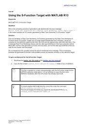
scalexio | page32<br />
Co-Workers on this issue: Dr. Ulrich Eisemann,<br />
Dr. Andreas Himmler, Dr. Heiko Kalte, Susanne Köhl,<br />
Holger Krisp, Andre Rolfsmeier, Holger Ross<br />
Editors and Translators: Robert Bevington,<br />
Stefanie Bock, Dr. Michelle Kloppenburg,<br />
Christine Smith<br />
Design: Krall & Partner, Düsseldorf, Germany<br />
Layout: Sabine Stephan<br />
Print: Media-Print Group GmbH, Paderborn<br />
santerno | page<br />
© Copyright <strong>2011</strong><br />
All rights reserved. Written permission is required<br />
for reproduction of all or parts of this publication.<br />
The source must be stated in any such reproduction.<br />
<strong>dSPACE</strong> is continually improving its products<br />
and reserves the right to alter the specifications of<br />
the products contained within this publication at<br />
any time without notice.<br />
<strong>dSPACE</strong> is a registered trademark of <strong>dSPACE</strong> GmbH<br />
in the United States or other countries, or both.<br />
See www.dspace.com/goto?trademarks for a list<br />
of further registered trademarks. Other brand<br />
names or product names are trademarks or registered<br />
trademarks of their respective companies<br />
or organizations.<br />
<strong>dSPACE</strong> <strong>Magazine</strong> 1/<strong>2011</strong> · © <strong>dSPACE</strong> GmbH, Paderborn, Germany · info@dspace.com · www.dspace.com<br />
6<br />
18<br />
northrop grumman | page
12<br />
autoliV | page<br />
satellite test systems | page52<br />
Contents<br />
3 eDitorial<br />
By Dr. Herbert Hanselmann,<br />
President<br />
Customers<br />
6 santerno<br />
Upvalue Energy<br />
Power inverters: Efficient energy transformation<br />
through efficient TargetLink code<br />
12 autoliV<br />
Gentle Belts<br />
Seat belts tightened the AUTOSAR way<br />
at Autoliv<br />
18 northrop grumman<br />
Turbine on Board<br />
Simulating gas turbine ship propulsion plant<br />
22 Dlr<br />
Blade Runner<br />
Developing and testing intelligent autonomous<br />
aircraft<br />
28 lemFÖrDer electronic<br />
Tested and Found Good<br />
Testing transmission lever electronics automatically<br />
with <strong>dSPACE</strong> test automation<br />
Products<br />
32 neW hil technology<br />
SCALEXIO<br />
Flexible work processes with new simulator<br />
technology<br />
38 microautoBox ii emBeDDeD pc<br />
Twice the Punch<br />
New option for MicroAutoBox II combines<br />
the best of two worlds<br />
42 controlDesK next generation<br />
signal eDitor<br />
Signals under Control<br />
The powerful new Signal Editor<br />
46 rapiDpro stanDarD conFigurations<br />
The Right System for Each<br />
Application<br />
RapidPro: Fulfill objectives faster with<br />
new standard configurations<br />
48 Ds1006 QuaD-core<br />
Connect 4<br />
Simulating several electric motors with<br />
the DS1006 Quad-Core<br />
Business<br />
52 satellite test systems<br />
Going into Orbit<br />
<strong>dSPACE</strong> pushes ahead with satellite<br />
test systems<br />
54 compact neWs<br />
<strong>dSPACE</strong> <strong>Magazine</strong> 1/<strong>2011</strong> · © <strong>dSPACE</strong> GmbH, Paderborn, Germany · info@dspace.com · www.dspace.com<br />
page 5
page 6 santerno<br />
Power inverters:<br />
Efficient energy transformation<br />
through efficient TargetLink code<br />
Upva<br />
<strong>dSPACE</strong> <strong>Magazine</strong> 1/<strong>2011</strong> · © <strong>dSPACE</strong> GmbH, Paderborn, Germany · info@dspace.com · www.dspace.com
lue<br />
Energy<br />
Every day, the amount of energy delivered by the<br />
sun is 15,000 times the current energy consumption<br />
worldwide. To exploit this natural energy<br />
source, solar energy has to be transformed into<br />
electrical energy. That’s where Santerno’s inverters<br />
are making a big impact.<br />
Solar fields are made more efficient by intelligent controllers.<br />
<strong>dSPACE</strong> <strong>Magazine</strong> 1/<strong>2011</strong> · © <strong>dSPACE</strong> GmbH, Paderborn, Germany · info@dspace.com · www.dspace.com<br />
page 7
page 8<br />
santerno<br />
Inverters and Their Application Fields<br />
Controlling industrial devices, solar<br />
fields, wind turbines and hybrid<br />
drives means controlling electric<br />
drives and handling high voltages<br />
and currents. A key part of the job<br />
is to convert direct current (DC)<br />
to alternating current (AC); this is<br />
done by a device called an inverter.<br />
A modern inverter can be described<br />
as a controller plus power stage<br />
electronics. For the application fields<br />
where Santerno’s products are used<br />
Setup of a solar field with inverters and control station.<br />
(see below), controllers have to be<br />
able to handle various hard realtime<br />
requirements and complex<br />
tasks depending on the application.<br />
n Solar Fields<br />
A photovoltaic (PV) field has to be<br />
controlled in terms of its optimal<br />
working point and efficient energy<br />
conversion. This is done by maximum<br />
power point tracking algorithms<br />
(MPPT) that find the best<br />
working point on the PV field,<br />
which varies throughout the day<br />
and in different weather conditions.<br />
The inverter DC link voltage has to<br />
be regulated to achieve efficient<br />
energy conversion, and the electrical<br />
current fed into the grid has to<br />
be regulated too. To meet certification<br />
standards, which also vary<br />
from country to country, several<br />
diagnostic and safety control functions<br />
have to be modeled to ensure<br />
a sufficient level of efficiency, total<br />
harmonic distortion (THD) and safety.<br />
<strong>dSPACE</strong> <strong>Magazine</strong> 1/<strong>2011</strong> · © <strong>dSPACE</strong> GmbH, Paderborn, Germany · info@dspace.com · www.dspace.com
“ When we use TargetLink, our power inverter mass production starts on time<br />
and meets our high quality standards.”<br />
n Wind Turbines<br />
Harnessing wind energy involves<br />
controlling the wind mill for optimal<br />
orientation, speed and safety<br />
conditions. The principles of DC<br />
link regulation and grid-injected<br />
current regulation are generally the<br />
same as for the solar applications.<br />
n Industrial Automation<br />
The enormous dynamics, high<br />
precision and accurate synchronization<br />
of modern drives and motion<br />
controls all need to be controlled.<br />
A typical example is a three-phase<br />
AC motor control by field-oriented<br />
control algorithms (FOC), vector<br />
torque control algorithms (VTC),<br />
and voltage on frequency (V/f)<br />
algorithms.<br />
Controller Software Structure<br />
for the Inverters<br />
The software for the “inverter<br />
system” can be functionally divided<br />
into an application layer and the<br />
platform software, which consists of<br />
a hardware abstraction layer (HAL),<br />
drivers, and services. Since services<br />
such as communication, diagnostics<br />
and calibration management and<br />
the hard real-time constraints are<br />
more or less identical in all the<br />
products, the platform software is the<br />
same for all controllers. Each controller<br />
only needs to be configured individually<br />
regarding real-time configurations,<br />
HAL mappings and service<br />
configurations to take specifics of<br />
the individual product into account.<br />
The cross-platform characteristic<br />
ensures better modularity and a<br />
shorter time to market for newer<br />
products. The application layer controls<br />
a physical plant such as a PV<br />
plant, a wind turbine, or a vehicle<br />
system and is developed individually<br />
for each product. The application<br />
layer can be further divided into<br />
subsystems such as the inverter layer<br />
and the application control layer, and<br />
is developed with <strong>dSPACE</strong> TargetLink ® .<br />
Controller Software Development<br />
Process<br />
The application layer is suited for<br />
model-based development.<br />
The tool chain at Santerno is based<br />
on MATLAB ® /Simulink ® /Stateflow ®<br />
for model-based design and Target Link<br />
for design, automatic production<br />
code generation and module testing.<br />
This tool chain is used in two different<br />
ways:<br />
n Refinements of existing controllers<br />
are often developed with Target Link,<br />
Fabio Gianstefani, Santerno<br />
which is used to generate code<br />
for the additional functionality that<br />
is afterwards integrated with the<br />
controller’s legacy code. These<br />
implementations are in floatingpoint<br />
arithmetic.<br />
n New controller developments are<br />
carried out exclusively using the<br />
model-based approach with automatic<br />
production code generation.<br />
This means that the complete<br />
application layer is generated<br />
automatically with TargetLink.<br />
The size of the control software<br />
is typically about 15,000-20,000<br />
lines of code. The most recent<br />
projects are developed in fixedpoint<br />
arithmetic.<br />
Challenges for Controller<br />
Development<br />
On the whole, there were two<br />
major challenges that had to be<br />
mastered for controller development.<br />
The first was optimization:<br />
because the controller software<br />
runs on a task synchronized with<br />
the bridge PWM carrier, for example<br />
11 kHz, its periodicity is lower than<br />
100 microseconds. These imposed<br />
execution time requirements could<br />
be handled due to TargetLink’s code<br />
efficiency in combination with using<br />
<strong>dSPACE</strong> <strong>Magazine</strong> 1/<strong>2011</strong> · © <strong>dSPACE</strong> GmbH, Paderborn, Germany · info@dspace.com · www.dspace.com<br />
page 9
page 10<br />
santerno<br />
In Brief<br />
The exploitation of natural<br />
energy sources requires efficient<br />
electrical devices. Part of the job<br />
is using inverters to convert<br />
direct current (DC) to alternating<br />
current (AC). Santerno’s inverters<br />
are equipped with controllers<br />
that ensure the greatest possible<br />
efficiency. Santerno has set<br />
up a development process that<br />
uses model-based design and<br />
automatic code generation for<br />
all controllers in the solar and<br />
wind energy application fields<br />
as well as in industrial automation.<br />
The experience from many<br />
production projects is that the<br />
benefits of using the <strong>dSPACE</strong><br />
TargetLink code generator helped<br />
the company to meet its high<br />
time-to-market and quality<br />
objectives. The development<br />
department therefore aims to<br />
extend this approach to all<br />
new product developments.<br />
The SUNWAY TG 600V and the SUNWAY M<br />
are examples of the inverter product line-up,<br />
equipped with control software generated<br />
by TargetLink.<br />
modeling guidelines to optimize the<br />
CPU usage that runs at 72 Mhz.<br />
The second challenge was the scaling<br />
technique: because the production<br />
code has to control different<br />
power electronic sizes, where the<br />
maximum currents and voltages<br />
may vary a lot, a worst-case scaling<br />
approach was not affordable, so all<br />
the electrical current and voltage<br />
magnitudes had to be normalized<br />
to the range of [-1…1] by means<br />
of division by the sensor/actuator<br />
maximum.<br />
Experience Gained<br />
Model-based design and automatic<br />
production code generation have<br />
proven to be a reliable and convincing<br />
method for developing control<br />
software. In particular, the testing,<br />
traceability and documentation in<br />
TargetLink’s development approach<br />
have turned out to be indispensable<br />
benefits for an efficient development<br />
process as they are decisive for high<br />
productivity and good quality:<br />
n Quick Back-to-Back Testing<br />
Executing the automatically<br />
generated code on the host PC<br />
in a software-in-the-loop test<br />
allows fewer and faster iterations<br />
and ensures high quality code once<br />
it is integrated on the real target<br />
for the first time. Software-in-theloop<br />
simulations also help greatly<br />
in properly scaling floating-point<br />
models for fixed-point implementations.<br />
The goal in the future<br />
will be to further increase the test<br />
coverage before the real integration<br />
of the product.<br />
n Proper Traceability<br />
Teamwork in development benefits<br />
from easy-to-understand models,<br />
which are basically a part of the<br />
specification, and good code readability,<br />
which is important during<br />
code reviews. The complete traceability<br />
between the model and the<br />
C code turned out to be especially<br />
useful for improving code maintenance.<br />
n Automatic Documentation<br />
Another time saver is the automatically<br />
generated documentation in<br />
HTML or PDF formats. The model<br />
serves as an executable specification<br />
and the automatically generated<br />
<strong>dSPACE</strong> <strong>Magazine</strong> 1/<strong>2011</strong> · © <strong>dSPACE</strong> GmbH, Paderborn, Germany · info@dspace.com · www.dspace.com
documentation of model and code<br />
can be extracted and integrated in<br />
specification and design documents<br />
as part of the documentation process.<br />
Conclusions and Outlook<br />
Many production projects have<br />
already been successfully completed<br />
at Santerno. During all of them, the<br />
time-to-market, performance and<br />
high quality objectives of the company<br />
were met. The goal of the<br />
Riccardo Morici<br />
Mr. Morici is System Modeling & Control<br />
Design Manager for the three product<br />
families at Santerno in Imola, Italy.<br />
development department is therefore<br />
to extend the model-based<br />
approach to all new product developments.<br />
In brief, the goal is to<br />
have more and more software automatically<br />
generated and meeting<br />
the stringent efficiency and quality<br />
requirements for Santerno’s products.<br />
Improving the development<br />
process based on the selected tools<br />
is one of the constant challenges.<br />
One of the reasons to choose<br />
Luca Balboni<br />
Mr. Balboni is the Team Leader Model-Based<br />
Control Systems responsible for embedded<br />
application software and identification of<br />
test vectors at Santerno in Imola, Italy.<br />
The solar field at Fuente Alamo, Spain, delivers up to 26 MW<br />
energy using inverters from Santerno.<br />
TargetLink is that certification of the<br />
code for solar inverters (both the<br />
platform and the application layer)<br />
is likely to be needed in some countries<br />
in the future, for example<br />
according to the ANSI/UL1998 standard<br />
in the USA. Using a modelbased<br />
approach with TargetLink will<br />
help meet those requirements.<br />
Riccardo Morici<br />
Luca Balboni<br />
Fabio Gianstefani, Santerno<br />
Fabio Gianstefani<br />
Mr. Gianstefani is Software Architecture<br />
Leader responsible for embedded software<br />
specification and integration at<br />
Santerno in Imola, Italy.<br />
<strong>dSPACE</strong> <strong>Magazine</strong> 1/<strong>2011</strong> · © <strong>dSPACE</strong> GmbH, Paderborn, Germany · info@dspace.com · www.dspace.com<br />
page 11
page 12<br />
ruBriK autoliVgB<br />
Gentle<br />
Belts Seat<br />
belts tightened the<br />
AUTOSAR way at Autoliv<br />
<strong>dSPACE</strong> <strong>Magazine</strong> 1/<strong>2011</strong> · © <strong>dSPACE</strong> GmbH, Paderborn, Germany · info@dspace.com · www.dspace.com
In a crash, seat belts have to respond fast, without impacting too heavily<br />
on their wearers. The solution is to use pretensioners, which tighten the<br />
belts during the very first fractions of a second. Autoliv’s active seat belt<br />
goes one step further by using a gentle pre-pretensioner that optimally<br />
softens belt impact. Its controllers use AUTOSAR-compliant software.<br />
Seat Belt Pre-Crash Systems<br />
At its location in Cergy near Paris,<br />
automotive supplier Autoliv is developing<br />
an electric seat belt pre-pretensioning<br />
system for production use<br />
by two different automobile manufacturers.<br />
This mechatronics system<br />
consists of a seat-belt retractor, an<br />
ECU and an electric motor (figure 1).<br />
As soon as emergency conditions are<br />
detected that are a potential pre-crash<br />
situation, such as panic braking or<br />
the vehicle being oversteered or<br />
understeered, the seat belt is electrically<br />
tightened to restrain its wearer<br />
before the accident. Then if an<br />
accident actually does occur, each<br />
vehicle occupant is ideally positioned<br />
in his or her seat, and the entire passive<br />
safety system, comprising pyrotechnical<br />
seat-belts and airbags, can<br />
deliver the best protection. If there is<br />
no accident, the belt is simply released.<br />
Not only does the device help reduce<br />
injuries in the event of an accident,<br />
it also delivers a warning to a driver<br />
who gets too close to safe driving<br />
limits, thereby acting as an active<br />
prevention device.<br />
Additionally, the pre-pretensioner’s<br />
comfort functions make the seat<br />
belt easy to put on and release, and<br />
dynamically adjust its tension to<br />
different driving situations.<br />
The ECU processes data on the environment<br />
and on vehicle dynamics<br />
received from other ECUs via the<br />
vehicle’s CAN bus, and provides<br />
control output to the electric motor<br />
for belt tensioning. The hardware<br />
platform for the ECU is a 32-bit<br />
microcontroller.<br />
OEM-Specific Processes<br />
The requirements for the ECU under<br />
development can be categorized as<br />
either functional or system-specific.<br />
The functional requirements for the<br />
application, in this case the belt<br />
tensioning logic, are implemented<br />
by Autoliv. They can take different<br />
forms: textual specifications, models,<br />
or initial software component descriptions<br />
in the ECU extract (see textbox<br />
Figure1: Autoliv’s seat belt pre-pretensioner<br />
holds the wearer in a better position before<br />
an accident occurs.<br />
<strong>dSPACE</strong> <strong>Magazine</strong> 1/<strong>2011</strong> · © <strong>dSPACE</strong> GmbH, Paderborn, Germany · info@dspace.com · www.dspace.com<br />
page 13
page 14<br />
autoliV<br />
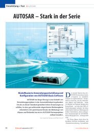
The AUTOSAR<br />
Workflow<br />
The Automotive Open System<br />
Architecture, or “AUTOSAR” for<br />
short, is a standard created by<br />
car manufacturers, ECU suppliers<br />
and tool providers to meet the<br />
increased requirements on the<br />
functionality and quality of in-<br />
vehicle software, while at the<br />
same time shortening development<br />
times. The standard<br />
AUTOSAR workflow begins with<br />
the OEM defining the system<br />
parameters, which comprise the<br />
network topology and ECU communication<br />
(messages, signals)<br />
as well as the distribution of<br />
application software to different<br />
ECUs in the network. The resulting<br />
system description is made<br />
available to the ECU manufacturers<br />
either as an AUTOSAR<br />
System Description file or as an<br />
“ECU extract from System Description”<br />
which contains only the<br />
data that are relevant for the<br />
specific ECU.<br />
The OEM can specify the software<br />
architecture in advance with different<br />
granularities, after which<br />
the supplier develops single software<br />
components for it. Implementations<br />
with the desired<br />
behaviors are then produced for<br />
the individual software components,<br />
either by reusing existing<br />
software components or by<br />
developing new functionalities.<br />
For new developments, a modelbased<br />
process can be used.<br />
The descriptions of the software<br />
components provide a frame for<br />
developing a MATLAB ® /Simulink ®<br />
model from which the AUTOSARcompliant<br />
production code is<br />
generated. The supplier configures<br />
the AUTOSAR basic software<br />
modules in accordance with the<br />
contracted AUTOSAR system<br />
description and also generates<br />
the code for these modules,<br />
which together with the code for<br />
the applications makes up the<br />
overall ECU software (figure 2).<br />
The AUTOSAR Workflow). To ensure<br />
smooth interaction with other ECUs<br />
installed in the vehicle, the OEM<br />
provides the system-specific requirements,<br />
for example, for ECU communication<br />
via the in-vehicle bus<br />
system (in this case, CAN). Depending<br />
on the OEM that Autoliv is working<br />
for, these requirements are also<br />
provided in the ECU extract obtained<br />
from the AUTOSAR system description,<br />
or they can take the form of<br />
a communication matrix (in this<br />
case, a DBC file describing the<br />
CAN communication).<br />
Modeling the ECU Application<br />
with SystemDesk and TargetLink<br />
The model-based development of<br />
application software and correct<br />
configuration of AUTOSAR basic<br />
software, and the integration of all<br />
the software on the target platform,<br />
are essential steps in the AUTOSAR<br />
development process.<br />
For the pre-pretensioner controller<br />
development, these tasks are being<br />
carried out by a combination of<br />
tools: the architecture software<br />
SystemDesk ® and the code generator<br />
TargetLink ® from <strong>dSPACE</strong>, and the<br />
configuration editor EB tresos ®<br />
Studio from Elektrobit (EB).<br />
To develop the AUTOSAR software<br />
Figure 2: Layered structure of the AUTOSAR software architecture.<br />
SWC<br />
SWC<br />
OS Mode<br />
Management<br />
SWC<br />
SWC<br />
AUTOSAR Runtime Environment (RTE)<br />
Firmware<br />
SWC<br />
Diagnostics Memory COM<br />
Services<br />
of the ECUs, Autoliv introduced the<br />
design flow depicted in Figure 3.<br />
Working in SystemDesk, the software<br />
architect imports the requirements<br />
from the ECU extract as a<br />
starting point for creating a detailed<br />
software architecture. The descriptions<br />
of the AUTOSAR services are<br />
also read in as further building<br />
blocks. Autoliv utilizes all the available<br />
design options for the software<br />
architecture to maximize reusability<br />
across different projects. The descriptions<br />
of the individual software<br />
components are then passed to<br />
the function developers in AUTOSAR<br />
format.<br />
The function developers import the<br />
AUTOSAR descriptions into TargetLink,<br />
where they can generate a frame<br />
model with the predefined inputs<br />
and outputs. The frame model is<br />
then filled either by reusing existing<br />
submodels or by modeling from<br />
scratch. The well-established modelin-the-loop<br />
(MIL) and software-in-theloop<br />
(SIL) simulation methods are<br />
used for testing and validation. Then<br />
the AUTOSAR-compliant production<br />
code is generated automatically<br />
by TargetLink. The entire function<br />
development process is distributed<br />
across several different Autoliv<br />
locations.<br />
CAN<br />
Application Layer<br />
Application<br />
Abstraction Layer<br />
Service Layer<br />
ECU Abstraction Layer<br />
<strong>dSPACE</strong> <strong>Magazine</strong> 1/<strong>2011</strong> · © <strong>dSPACE</strong> GmbH, Paderborn, Germany · info@dspace.com · www.dspace.com<br />
Microcontroller<br />
Abstraction Layer
Software<br />
Architecture<br />
Design<br />
AUTOSAR<br />
services<br />
Figure 3: AUTOSAR design flow used at Autoliv.<br />
Configuring the AUTOSAR Basic<br />
Software with EB tresos Studio<br />
Autoliv’s software integrator starts<br />
work in parallel to the application<br />
software development. The developer<br />
configures and generates the<br />
ECU’s basic software with EB tresos<br />
Studio. Different OEMs specify the<br />
basic software to be used in different<br />
ways, using the EB tresos Auto-<br />
Core as the basis. This contains the<br />
AUTOSAR modules, including the<br />
XML<br />
SystemDesk Software<br />
architecture<br />
TargetLink<br />
XML<br />
BSW<br />
Configuration<br />
XML<br />
EB tresos Studio/ EB tresos AutoCore<br />
Modelling /<br />
Code<br />
Generation<br />
Workflow<br />
BSW<br />
Generation<br />
AUTOSAR run-time environment<br />
(RTE) and the hardware-specific<br />
microcontroller abstraction layer<br />
(MCAL). Different OEM-specific<br />
modules are added to the modules<br />
in the EB tresos AutoCore and integrated<br />
to create complete, OEM-<br />
Application<br />
source files<br />
.c<br />
.c<br />
.h<br />
BSW<br />
source files<br />
.h<br />
ECU software<br />
Compilation<br />
BSW: Basic Software<br />
XML: Extensible Markup<br />
Language<br />
specific basic software. One of<br />
AUTOSAR’s main advantages comes<br />
into play here, enabling Autoliv to<br />
integrate the seat belt pre-pretensioner<br />
application into ECUs with<br />
different basic software implementations.<br />
It is essential that the software<br />
“ Working with SystemDesk greatly improved<br />
software reusability across projects.”<br />
Claude Redon, Autoliv<br />
<strong>dSPACE</strong> <strong>Magazine</strong> 1/<strong>2011</strong> · © <strong>dSPACE</strong> GmbH, Paderborn, Germany · info@dspace.com · www.dspace.com<br />
page 15
page 16<br />
ruBriK autoliVgB<br />
Strength in Unity<br />
“Cooperate on standards, compete<br />
on implementation” is the<br />
philosophy behind the AUTOSAR<br />
consortium’s standardization<br />
activities. Since 2006 cooperation<br />
is also a driving force for <strong>dSPACE</strong><br />
and EB, both Premium Members<br />
in the consortium right from the<br />
beginning. Their joint efforts<br />
focus on their software tools,<br />
and on ensuring that they work<br />
together smoothly according to<br />
the AUTOSAR design methodology.<br />
<strong>dSPACE</strong>’s contribution is<br />
its established software architecture<br />
and simulation tool System-<br />
Desk and its production-proven<br />
code generator TargetLink, while<br />
Elektrobit provides productionready<br />
AUTOSAR basic software<br />
with its products EB tresos<br />
AutoCore and EB tresos Studio.<br />
Together, these form a complete,<br />
well-coordinated tool chain covering<br />
AUTOSAR design methods<br />
from the software architecture<br />
description to model-based application<br />
development, to the configuration<br />
and generation of the<br />
electronic control unit’s (ECU’s)<br />
basic software on the target<br />
platform, thereby covering all the<br />
layers of the AUTOSAR standard<br />
software architecture as shown<br />
in figure 1. This extremely practical<br />
solution for ECU development<br />
benefits OEMs and their<br />
Tier 1 suppliers alike.<br />
“ Early software verification was achieved by<br />
performing back-to-back tests with TargetLink.”<br />
components comply with the<br />
AUTOSAR standard (in this case, a<br />
mixture of AUTOSAR Release 3.0<br />
and 3.1) and also with the interface<br />
specifications, so that they can be<br />
connected via the AUTOSAR run-time<br />
interface (RTE) with no problems.<br />
From Architecture to Production<br />
Code<br />
The AUTOSAR basic software is<br />
configured by reading the software<br />
architecture that was exported from<br />
SystemDesk, plus the ECU extract<br />
or the DBC file, into EB tresos<br />
Studio. This process results in a preconfigured<br />
RTE and preconfigured<br />
communication modules. To complete<br />
the RTE configuration, the<br />
data elements of the individual<br />
software components’ ports are<br />
mapped to the signals in the bus<br />
communication (data-to-signal<br />
mapping), the runnables are<br />
assigned to operating system tasks<br />
(runnable-to-task mapping), and<br />
the service ports are connected to<br />
the appropriate ports on the software<br />
components (service port<br />
mapping).<br />
Next, the integrator configures the<br />
parameters of the basic software<br />
modules in EB tresos Studio, partly<br />
using script automation. Then code<br />
is generated in EB tresos Studio to<br />
produce the complete source code<br />
for the AUTOSAR basic software.<br />
This is passed to the build environment<br />
together with the source code<br />
for the application components from<br />
TargetLink. The final result is the<br />
executable binary code, which is<br />
used to program the ECU. Figure 4<br />
illustrates the resulting software<br />
layers and shows which tools are<br />
used for which steps.<br />
Claude Redon, Autoliv<br />
Benefit from Cooperation<br />
<strong>dSPACE</strong>’s and EB’s early and continued<br />
commitment to this demanding<br />
automobile industry standard is<br />
reflected in the tools that they supply.<br />
The tools combine perfectly to harness<br />
the two companies’ core areas of<br />
expertise: the model-based development<br />
of application software and<br />
the creation of software run-time<br />
platforms for ECUs. The parts of the<br />
specification required for applying<br />
the AUTOSAR standard are mapped<br />
to the tools to make developers’<br />
work easier. The advantages of<br />
AUTOSAR for the reliable development<br />
of reusable software are combined<br />
with the model-based methods<br />
used to develop that software efficiently.<br />
The tools support the specification<br />
and generation of software,<br />
provide generators and automated<br />
steps, and help ensure seamless consistency<br />
and validation. The systematic<br />
use of standardized AUTOSAR<br />
descriptions ensures that the tools<br />
interact smoothly.<br />
Wherever there are still specification<br />
gaps in the standard, the tool manufacturers<br />
consult to avoid incompatibilities.<br />
Pragmatic solutions are<br />
found and tested to prevent in<br />
advance any technical problems<br />
that might occur.<br />
At Autoliv, the <strong>dSPACE</strong> and EB tresos<br />
products were supplemented by process<br />
consultation in introduction<br />
projects based on AUTOSAR. Experts<br />
from <strong>dSPACE</strong> and EB gave on-site<br />
support to ensure efficient tool use.<br />
Project Experience<br />
Autoliv is fully committed to the<br />
AUTOSAR standard in these projects.<br />
The initial investments for introducing<br />
AUTOSAR are already being off-<br />
<strong>dSPACE</strong> <strong>Magazine</strong> 1/<strong>2011</strong> · © <strong>dSPACE</strong> GmbH, Paderborn, Germany · info@dspace.com · www.dspace.com
Software<br />
Architecture<br />
Design<br />
SystemDesk<br />
TargetLink<br />
BSW<br />
Configuration<br />
and<br />
Generation<br />
EB tresos Studio<br />
AUTOSAR<br />
SWC<br />
1<br />
Figure 4: The structure of the final ECU software.<br />
set by considerable improvements in<br />
software development. Two of the<br />
benefits are explicit software modularization<br />
and improved reuse of the<br />
application software. The systematic<br />
use of the standardized AUTOSAR<br />
exchange formats gives optimum<br />
support to all the individual process<br />
steps. The AUTOSAR methods are<br />
AUTOSAR<br />
SWC<br />
2<br />
AUTOSAR<br />
SWC<br />
3<br />
RTE<br />
Application<br />
EB tresos AutoCore<br />
OEM specific BSW modules<br />
MCAL<br />
AUTOSAR R3.x<br />
32-bit microcontroller<br />
AUTOSAR<br />
SWC<br />
N<br />
ideal for combining with modelbased<br />
function development and<br />
automatic production code generation.<br />
The experience gathered and<br />
the results achieved in these projects<br />
show that the <strong>dSPACE</strong> and EB tools<br />
are a complete success in these very<br />
tool-supported developments. Continuous<br />
further development, based<br />
In Brief<br />
For optimum safety, seat belt<br />
pre-pretensioners hold their<br />
wearers in a better position<br />
before an accident occurs. They<br />
also act as an active prevention<br />
device by delivering a warning to<br />
the driver who gets too close to<br />
safe driving limits. The controller<br />
for Autoliv’s latest pre-pretensioner<br />
has been developed in compliance<br />
with the AUTOSAR standard.<br />
The design flow is based on the<br />
SystemDesk architecture software<br />
and the TargetLink code generator<br />
from <strong>dSPACE</strong> for developing<br />
the application layer. The basic<br />
software is configured with EB<br />
tresos Studio from Elektrobit.<br />
Easy software modularization and<br />
improved reuse of the application<br />
software are two of the benefits<br />
Autoliv experienced during development.<br />
on new versions of the standard and<br />
on the requirements of ongoing<br />
projects, keeps the products up-todate<br />
and guarantees proven tool<br />
interaction.<br />
Peter Kirsch, Elektrobit<br />
Claude Redon, Autoliv<br />
Joachim Stroop, <strong>dSPACE</strong><br />
Pictured left to right are:<br />
Claude Redon<br />
Mr. Redon is a software architect with<br />
responsibility for the pre-pretensioner<br />
family at Autoliv in Cergy, France.<br />
Joachim Stroop<br />
Mr. Stroop is Lead Product Manager with<br />
responsibility for the SystemDesk tool at<br />
<strong>dSPACE</strong> GmbH in Paderborn, Germany.<br />
Peter Kirsch<br />
Mr. Kirsch is Product Manager with responsibility<br />
for the tool EB tresos Studio at<br />
Elektrobit Automotive GmbH, Erlangen,<br />
Germany.<br />
<strong>dSPACE</strong> <strong>Magazine</strong> 1/<strong>2011</strong> · © <strong>dSPACE</strong> GmbH, Paderborn, Germany · info@dspace.com · www.dspace.com<br />
page 17
page 18<br />
© Photo: U.S. Navy<br />
northrop grumman<br />
Figure 1: Unlike classic aircraft carriers, large-deck assault ships like the Makin Island have<br />
no aircraft launch catapult. They serve as bases for helicopters, vertical-takeoff planes and<br />
landing craft.<br />
The USS Makin Island is the first large-deck<br />
assault ship in the U.S. Navy to be powered by<br />
a combination of gas turbines and electric motors.<br />
The new propulsion system considerably reduces<br />
fuel consumption and maintence costs when<br />
compared with the steam turbine-based propulsion<br />
otherwise used in this class of ship, yet without<br />
compromising performance. To test the control<br />
software for the gas turbine propulsion system,<br />
manufacturer Northrop Grumman used a <strong>dSPACE</strong><br />
system on board the ship itself.<br />
Gas Turbine Saves Fuel<br />
When General Electric brought out<br />
the LM2500+ gas turbine with<br />
35,000 HP in the late 1990s, it was<br />
a logical step for the U.S. Navy to<br />
equip new ships with this propulsion<br />
plant due to the clear advantages<br />
of gas turbines over the<br />
steam turbines previously used: Performance<br />
being equal, they are not<br />
only more compact, lighter, and<br />
easier to maintain, they are also<br />
quicker to get running and require<br />
less manning. So the latest largedeck<br />
assault ship, the Makin Island<br />
(named for an atoll in the Pacific),<br />
which went into service in 2009, is<br />
powered by two LM2500+ gas turbines.<br />
At speeds under 12 knots<br />
(just over 22 km/h), two 5000-HP<br />
<strong>dSPACE</strong> <strong>Magazine</strong> 1/<strong>2011</strong> · © <strong>dSPACE</strong> GmbH, Paderborn, Germany · info@dspace.com · www.dspace.com<br />
The USS Makin Island went into service in 2009<br />
and is the first large-deck assault ship in the U.S.<br />
Navy to be powered by gas turbines.
Simulating Gas Turbine Ship Propulsion Plant<br />
Turbine<br />
on Board<br />
<strong>dSPACE</strong> <strong>Magazine</strong> 1/<strong>2011</strong> · © <strong>dSPACE</strong> GmbH, Paderborn, Germany · info@dspace.com · www.dspace.com<br />
page 19
page 20<br />
northrop grumman<br />
© GE Marine<br />
Air inlet Air outlet<br />
Figure 2: The Makin Island has two LM2500+ type General Electric gas turbines that together<br />
generate 70,000 shaft horsepower. A <strong>dSPACE</strong> system was used to test the Woodward<br />
Governor Company MicroNet TM ECU.<br />
electric motors take over propulsion,<br />
saving up to 25% of the gas<br />
turbines’ operating time and approx.<br />
1.5 million liters of fuel every year.<br />
Because the Makin Island is the first<br />
ship in the U.S. Navy to use the<br />
LM2500+ turbine, the associated<br />
control software had to be completely<br />
readapted and tested. This<br />
work required shipboard simulation<br />
of all the signal traffic between the<br />
Direction to propeller<br />
electronic control unit (ECU) and the<br />
gas turbine, so a powerful, simulation-based,<br />
extremely flexible realtime<br />
test system was needed.<br />
Simulating Signal Traffic<br />
Northrop Grumman’s engineers<br />
faced the paradoxical task of testing<br />
the ECU’s turbine emergency shutdown<br />
and warning functions without<br />
actually operating the turbine,<br />
since this was a condition of their<br />
contract with the U.S. Navy. The<br />
ECU was significantly different than<br />
its counterparts on other ship classes,<br />
and actually had to monitor a normal<br />
engine startup prior to engaging<br />
the engine’s protective features.<br />
The only way to do this was to simulate<br />
the turbine’s signals to make<br />
the ECU “think” that the turbine<br />
was really running. Simulating turbine<br />
startup was a major challenge<br />
for the test system, because during<br />
the start sequence the ECU expects<br />
the turbine to send numerous signals<br />
(temperature, pressure, speed<br />
and so on) with specific values and<br />
rates-of-change at various points in<br />
time. If these return signals do not<br />
fit the expected reference values,<br />
the ECU immediately aborts the<br />
start sequence. “Unfortunately, it<br />
was not possible to use manual settings<br />
to trick the ECU into its Run<br />
status,” explains James Turso, an<br />
engineer at Northrop Grumman.<br />
“So we had to simulate the complex<br />
start sequence before we could<br />
begin testing the ECU’s turbine<br />
emergency shutdown and warning<br />
functions.”<br />
Figure 3: To test the MicroNet TM ECU, a <strong>dSPACE</strong> system simulates all the signal traffic between the turbine and the ECU. The turbine model<br />
was developed in MATLAB ® /Simulink ® .<br />
Micronet turbine controller<br />
<strong>dSPACE</strong> System<br />
Simulink ® turbine model<br />
Signalconditioning<br />
I/O<br />
The main turbine signals to be simulated:<br />
� Position of the fuel metering valve<br />
� Speed of gas generator and power turbine<br />
� Signals from stator vane actuators<br />
� Diverse pressure signals<br />
� Diverse temperature signals<br />
� Signals from vibration sensors<br />
� Lube oil pressure<br />
Processor board<br />
<strong>dSPACE</strong> <strong>Magazine</strong> 1/<strong>2011</strong> · © <strong>dSPACE</strong> GmbH, Paderborn, Germany · info@dspace.com · www.dspace.com
Choice of Test System<br />
For gas turbine simulation, engineers<br />
at Northrop Grumman specified a<br />
hardware-in-the-loop (HIL) simulator<br />
that had to fulfill a whole series of<br />
requirements:<br />
n Real-time capability with a maximum<br />
model throughput time of<br />
5 ms (the turbine model was<br />
developed in MATLAB ® /Simulink ® )<br />
n Signal conditioning capability<br />
(to exchange signals with the<br />
Woodward Governor Company<br />
MicroNetTM ECU)<br />
n All sequences software-controllable<br />
n Uncomplicated, flexible connection<br />
of test hardware to the ship’s<br />
electrical system, i.e., without<br />
adapting the ECU, the gas turbine<br />
or the cabling<br />
n Fail-safe, industry-proven system<br />
To be certain of meeting this requirement<br />
profile, Northrop Grumman<br />
decided to use modular hardware<br />
and software components from the<br />
<strong>dSPACE</strong> tool chain.<br />
<strong>dSPACE</strong> System Simulates Gas<br />
Turbines<br />
To present a realistic operational gas<br />
turbine to the ECU, the <strong>dSPACE</strong> system<br />
had to simulate a wide range<br />
of different turbine signals (figure 3):<br />
signals for pressure, temperature<br />
and acceleration, the speeds of the<br />
gas generator and power turbine,<br />
lubricant pressure, etc. “But the<br />
biggest challenge was to simulate<br />
the signals of the fuel metering<br />
valve position feedback signal,<br />
which works on the principle of an<br />
LVDT,” adds James Turso. An LVDT<br />
(linear variable differential transformer)<br />
is an inductive sensor that<br />
generates a high-frequency AC voltage<br />
signal with a variable amplitude.<br />
In the Makin Island’s gas turbines,<br />
the signal shape depends on the<br />
current opening of the fuel valve,<br />
which changes constantly throughout<br />
the start sequence (figure 4).<br />
FMV Position (%)<br />
70<br />
60<br />
50<br />
40<br />
30<br />
20<br />
10<br />
0<br />
Autostart<br />
Sequence<br />
Controlling Simulation<br />
via GTWS<br />
Idle<br />
-10<br />
0 100 200 300 400 500 600<br />
Figure 4: Time behavior of fuel metering valve position (actually the position feedback signal<br />
from the <strong>dSPACE</strong> equipment processed by the ECU) during the propulsion system’s startup<br />
sequence. Simulating the LVDT for this was the greatest challenge in the tests.<br />
“ Given the tight time constraints on this project,<br />
the <strong>dSPACE</strong> system enabled us to meet the<br />
U.S. Navy’s tough gas turbine ECU test specifications.”<br />
James A. Turso, Northrop Grumman<br />
“With the <strong>dSPACE</strong> HIL system, the<br />
simulation of this complex signal<br />
works perfectly,” concludes James<br />
Turso.<br />
All Tests Successful<br />
With the aid of the gas turbine simulation<br />
by the <strong>dSPACE</strong> HIL system,<br />
Northrop Grumman engineers<br />
brought the various ECU safety and<br />
emergency shutdown function tests<br />
stipulated by the U.S. Navy to a successful<br />
conclusion. The <strong>dSPACE</strong> HIL<br />
system proved its high flexibility in<br />
all these tasks and will be used<br />
again in any future new-engine<br />
startup tests. And as all forms of<br />
shipbuilding face increasing complexity,<br />
such a HIL system would<br />
Time (sec)<br />
Power Turbine Load<br />
Added in Simulation<br />
also be invaluable in testing control<br />
systems for other types of components.<br />
The days when tests could be<br />
performed just by adjusting controls<br />
and switches manually are fast coming<br />
to an end.<br />
James A. Turso Ph.D., P.E<br />
is a Fellow engineer at Northrop Grumman,<br />
USA.<br />
Source : Proceedings of ASME Turbo Expo<br />
2010: Power for Land, Sea and Air<br />
GT2010<br />
June 14-18, 2010, Glasgow, UK<br />
GT2010−223050<br />
<strong>dSPACE</strong> <strong>Magazine</strong> 1/<strong>2011</strong> · © <strong>dSPACE</strong> GmbH, Paderborn, Germany · info@dspace.com · www.dspace.com<br />
page 21
page seite 22 Dlr<br />
Blade<br />
Runner<br />
Developing and testing intelligent autonomous aircraft<br />
<strong>dSPACE</strong> <strong>Magazine</strong> 1/<strong>2011</strong> · © <strong>dSPACE</strong> GmbH, Paderborn, Germany · info@dspace.com · www.dspace.com
Prometheus, the newest member of the Institute<br />
of Flight Systems’ research fleet.<br />
In Do Androids Dream<br />
of Electric Sheep?,<br />
a science fiction story<br />
by Philip K. Dick and<br />
later the action film<br />
Blade Runner, a central<br />
question is whether<br />
autonomous, high-tech<br />
machines are capable<br />
of dreaming. If they are,<br />
what do the German<br />
Aerospace Center’s<br />
unmanned research<br />
aircraft ARTIS and Prometheus<br />
dream of?<br />
They dream of their<br />
experimental flight<br />
environment, of possible<br />
missions and, even<br />
more exciting, of missions<br />
yet impossible.<br />
<strong>dSPACE</strong> <strong>Magazine</strong> 1/<strong>2011</strong> · © <strong>dSPACE</strong> GmbH, Paderborn, Germany · info@dspace.com · www.dspace.com<br />
seite page 23
page seite 24 Dlr<br />
Anntena Magnetometer Remote control Sonar Current supply GPS<br />
Mission Impossible<br />
The missions under investigation<br />
by researchers at the German Aerospace<br />
Center’s (DLR) Institute of<br />
Flight Systems are dangerous, dirty,<br />
and dull. Only missions like these<br />
justify the expense of developing<br />
unmanned aircraft. For all other<br />
missions, the hand on the control<br />
stick has always been, and will always<br />
be, human. But wherever<br />
someone – or something – has to<br />
enter an obstacle-ridden scenario,<br />
investigate a disaster site, fly at high<br />
risk under extreme conditions, or<br />
make tedious relay or inspection<br />
flights, unmanned aerial vehicles<br />
(UAV) come into their own. In theory.<br />
And to some extent in practice:<br />
Modern UAVs can fly along preplanned<br />
waypoints, and some can<br />
take off and land automatically.<br />
However, there is not a single UAV<br />
that is allowed or even able to operate<br />
in Germany’s general airspace,<br />
because at the moment, they quite<br />
simply lack the ability to “see” their<br />
IMU Antenna<br />
environment and react to it appropriately.<br />
Artificial Sensory Organs<br />
This is where the research begins.<br />
To perceive its environment, a UAV<br />
needs additional equipment such as<br />
image sensors for a two-dimensional,<br />
or even better, three-dimensional<br />
view of its surroundings. Cameras,<br />
radar and laser scanners can all be<br />
used. The captured sensor data<br />
must then be processed in real time<br />
so that the results can be used for<br />
flight control. A decision system or<br />
mission manager also has to be<br />
developed; this will receive environmental<br />
data and UAV-specific data<br />
and use it to assess options, make<br />
decisions, and if necessary even<br />
change the route or abort the mission<br />
in an emergency. The flight<br />
controller also has to meet tougher<br />
requirements, especially with regard<br />
to its precision and its ability to utilize<br />
the aircraft’s maximum flight<br />
performance.<br />
Flight control<br />
processor<br />
Image processing<br />
30 cm<br />
Stereo camera<br />
DLR’s research UAVs (like ARTIS here) contain numerous onboard systems. These are used for stabilization, flying preset trajectories, automatic<br />
take-off and landing, and so on.<br />
Flying Research Platform<br />
But before even beginning to tackle<br />
these demanding tasks, a suitable<br />
research platform and infrastructure<br />
have to be set up. Looking round<br />
the market to find a suitable experiment<br />
platform, one very quickly<br />
realizes that an off-the-shelf system<br />
will never fulfill these very particular<br />
research needs. Only a custom development<br />
can provide the necessary<br />
combination of special, powerful,<br />
modular sensors and processors,<br />
open interfaces and easy programmability<br />
to meet the need for a<br />
large payload and good usability.<br />
It also covers certification aspects<br />
and customer expectations, and<br />
ensures that the basic system,<br />
measuring equipment, onboard<br />
electronics and flight control processor<br />
are optimally coordinated.<br />
Technical Components<br />
The research platforms that were<br />
developed consist of flight control<br />
computers, different data commu-<br />
<strong>dSPACE</strong> <strong>Magazine</strong> 1/<strong>2011</strong> · © <strong>dSPACE</strong> GmbH, Paderborn, Germany · info@dspace.com · www.dspace.com
World modeling and mapping in real time during fully automated flight over unknown terrain.<br />
nication devices, a high-precision<br />
GPS receiver system, a three-axis<br />
acceleration and rotation speed sensor,<br />
and a sonar device for measuring<br />
the altitude above ground. A threeaxis<br />
magnetometer is also included.<br />
These modules are all needed to<br />
stabilize the UAV, to fly it on preset<br />
trajectories, and to have it take off<br />
and land automatically. The individual<br />
vehicles are all fitted with<br />
the same sensors and control processors.<br />
Each of the three ARTIS<br />
helicopters (midiARTIS, meARTIS<br />
and maxiARTIS) implements a different<br />
drive concept: two-stroke engine,<br />
electric drive or turbine. The rotors<br />
are between two and three meters<br />
in diameter, and the maximum takeoff<br />
weight is 25 kg. Prometheus, in<br />
contrast, is a pusher propeller airplane<br />
with a twin-tail unit. Collectively,<br />
these aircraft cover tasks that<br />
demand highly precise navigation<br />
in a confined space, and also tasks<br />
that require a long range and high<br />
flying speed.<br />
Mathematical Description<br />
of Flight Behavior<br />
While the real flying system is being<br />
set up, a mathematical description<br />
of the system’s mechanical flight<br />
behavior also has to be developed.<br />
This is the basis for setting up a<br />
flight controller that will automatically<br />
stabilize the aerial vehicle and<br />
steer it towards waypoints. Physical<br />
relations and captured data (from<br />
wind tunnel tests, for example) are<br />
combined to create a simulation<br />
model of the aerial vehicle. The<br />
model’s parameters can be determined<br />
precisely by applying the<br />
same control inputs to the real flying<br />
system and to the model, recording<br />
the responses of both, and minimizing<br />
the differences between their<br />
responses by adjusting the model<br />
parameters. If the model’s behavior<br />
and the real behavior are not consistent<br />
enough, the model can be<br />
extended or refined in an iterative<br />
process. The result is a precise,<br />
numerically and analytically acces-<br />
ARTIS, the<br />
Autonomous UAV<br />
At the DLR’s Institute of Flight<br />
Systems in Braunschweig,<br />
Germany, researchers are using<br />
small unmanned helicopters to<br />
develop an experimental aerial<br />
vehicle called ARTIS (Autonomous<br />
Rotorcraft Testbed for<br />
Intelligent Systems). The project<br />
aims to investigate new kinds<br />
of systems and algorithms for<br />
autonomous, intelligent functions<br />
and evaluate them in<br />
experiments. In addition to an<br />
onboard computer and data link,<br />
ARTIS has a variety of sensors<br />
such as satellite navigation (GPS),<br />
an inertial measurement platform<br />
and a magnetometer.<br />
Imaging sensors (such as video<br />
cameras) are extremely important.<br />
Functions for machine<br />
decision- making, collision avoidance,<br />
and cooperation between<br />
several flight systems are major<br />
research focuses, in addition<br />
to advanced flight control and<br />
flight guidance concepts. Realtime<br />
image processing systems<br />
are also used for experiments<br />
on optically supported navigation<br />
and world modeling.<br />
sible description of the controlled<br />
system.<br />
Developing a Flight Controller<br />
Model<br />
This model was implemented in<br />
MATLAB ® /Simulink ® and then immediately<br />
used to develop the controller<br />
in a desktop simulation. However, to<br />
perform its tasks, the flight controller<br />
requires precise information on the<br />
vehicle’s attitude and position, so<br />
the navigation algorithms also had<br />
<strong>dSPACE</strong> <strong>Magazine</strong> 1/<strong>2011</strong> · © <strong>dSPACE</strong> GmbH, Paderborn, Germany · info@dspace.com · www.dspace.com<br />
seite page 25
page 26 Dlr<br />
<strong>dSPACE</strong> Simulator<br />
Sensor Emulation<br />
Sensor<br />
Drivers<br />
GCS Computer<br />
Hardware-in-The-Loop Simulation Environment<br />
State Vehicle Simulation<br />
Model<br />
Control<br />
to be included in the simulation.<br />
Since navigation uses the individual<br />
sensors, these were also represented<br />
in the simulation with their protocols<br />
and their noise and time behavior.<br />
These sensor simulations take the<br />
data they need from the simulation<br />
of flight mechanics. The simulation<br />
also includes a wind and gust model,<br />
Real-Time Simulation<br />
This approach cannot be used to<br />
investigate the functioning and<br />
behavior of the flight control computer,<br />
especially with regard to its<br />
real-time capability and correct connection<br />
to the hardware interfaces. A<br />
<strong>dSPACE</strong> system provided the solution:<br />
to partition the simulation, largely<br />
The <strong>dSPACE</strong> system simulates all the sensor<br />
data, so for the UAVs, the simulated flight<br />
in the laboratory is just like a real flight.<br />
Flights in the Lab<br />
In practical terms, all the sensors<br />
are simply disconnected from the<br />
flight control computer and substituted<br />
by <strong>dSPACE</strong>-simulated sensor<br />
data via compatible connector<br />
plugs. The flight control computer<br />
processes the serial data with the<br />
original drivers and settings, computes<br />
a navigation solution, and<br />
generates a command. The command<br />
is directly executed via the<br />
original actuators and also returned<br />
to the <strong>dSPACE</strong> system. The latter<br />
uses the command itself, the system<br />
dynamics and the environment to<br />
calculate a response to the command,<br />
and then simulates the corresponding<br />
sensor data. To return<br />
to the image of the dreaming air-<br />
“ Two factors contribute to the successful development of unmanned aerial<br />
vehicles, but they are seldom mentioned and always underestimated:<br />
the safety pilot and the <strong>dSPACE</strong> system for hardware-related simulation.<br />
Both of them considerably reduce the ‘drop height’ of test flights.”<br />
plus a ground contact model for<br />
take-off and landing. An interface<br />
to the UAV’s ground control station<br />
was set up for easy and realistic handling.<br />
Another interface to the outside<br />
world allows the position and<br />
attitude of the simulated system in<br />
its environment to be visualized. All<br />
these elements make it possible to<br />
plan, fly and observe entire missions<br />
in the laboratory. Controller development,<br />
parameter tuning, protocol<br />
tests, communication tests, and test<br />
flight preparation can all be performed<br />
within this infrastructure.<br />
Actuator Simulation<br />
Sensor Raw Data Actuator Raw Data<br />
Sensor<br />
Data<br />
Ground control station (GCS)<br />
Navigation<br />
Filter<br />
State Estimate<br />
Flight Controller Control Actuator<br />
and Mission Control<br />
Driver<br />
Telemetry Instructions<br />
QNX Real-Time OS<br />
GCS Software MAESTRO<br />
User Interface, Mission Planning Windows ® XP<br />
using the same function blocks that<br />
were developed under Simulink. The<br />
navigation and flight controller were<br />
taken out of the simulation and performed<br />
by the original flight control<br />
computer instead. All other functions<br />
were ported to the <strong>dSPACE</strong> system,<br />
where they provide real-time simulation<br />
of the sensors, the environment,<br />
the flight mechanics and the actuator<br />
dynamics. Additional conditions such<br />
as wind, sensor noise and the failure<br />
of entire sensors can easily be set in<br />
the <strong>dSPACE</strong> ControlDesk ® experiment<br />
software.<br />
Dr.-Ing. Gordon Strickert, German Aerospace Center (DLR)<br />
craft: The UAV dreams of its mission<br />
and reacts accordingly, all the<br />
time sitting safely in the laboratory.<br />
System Tests<br />
This kind of hardware-in-the-loop<br />
(HIL) simulation has proven to be<br />
extremely useful and is being used<br />
intensively in development. Subsystem<br />
tests, final system tests, algorithm<br />
adjustment, interface tests,<br />
etc., are always performed in this<br />
environment. The simulation is also<br />
combined with the powerful visualization<br />
environment and used for<br />
<strong>dSPACE</strong> <strong>Magazine</strong> 1/<strong>2011</strong> · © <strong>dSPACE</strong> GmbH, Paderborn, Germany · info@dspace.com · www.dspace.com
parameter studies, quality management<br />
and, last but not least, realtime<br />
presentations.<br />
Virtual Flying Class<br />
The UAVs have by now learned to<br />
fly in this simulation environment:<br />
beginning with careful hovering<br />
for the helicopters, then waypoint<br />
flight, automatic take-off and landing,<br />
and finally even aggressive<br />
rapid flight along what are called<br />
three-dimensional spline paths.<br />
Methods of automatic world<br />
model ing and processing, and of<br />
three-dimensional map creation,<br />
are currently being tested here.<br />
This means that the new environment<br />
sensors also have to be integrated<br />
into the HIL simulator for<br />
simulation.<br />
Real Missions<br />
The experimental aerial vehicles<br />
regularly have to withstand the test<br />
of real flight missions. The cables to<br />
the <strong>dSPACE</strong> system are removed for<br />
these, and the normal sensors are<br />
connected. Software modifications<br />
or reconfiguration are not necessary.<br />
Thanks to uncountable hours on<br />
the simulator, the system behavior<br />
is already known with sufficient<br />
precision, and test flights seldom<br />
produce surprises. The team can<br />
concentrate fully on real, non-simulated<br />
effects and complications.<br />
Autonomous Helicopter<br />
As a result of this work, ARTIS is one<br />
of only a few automatic helicopters<br />
in the world that can move across<br />
unknown terrain, create a map of<br />
their environment completely independently,<br />
and operate within that<br />
environment collision-free. The test<br />
flights are turning what were once<br />
machine dreams into tangible,<br />
measurable realities.<br />
Dr.-Ing. Gordon Strickert,<br />
DLR Braunschweig<br />
Automatic route planning in complex lowlevel<br />
flight scenarios.<br />
In Brief<br />
n Developing autonomous<br />
unmanned aerial vehicles<br />
n Simulating complex spatial<br />
environment models in<br />
real time<br />
n Optimizing the controller<br />
on the <strong>dSPACE</strong> Simulator<br />
Dr.-Ing. Gordon Strickert<br />
Dr. Strickert is a research associate<br />
developing unmanned flying aircraft<br />
at the DLR’s Institute of Flight Systems<br />
in Braunschweig, Germany.<br />
<strong>dSPACE</strong> <strong>Magazine</strong> 1/<strong>2011</strong> · © <strong>dSPACE</strong> GmbH, Paderborn, Germany · info@dspace.com · www.dspace.com<br />
seite page 27
page 28 lemFÖrDer electronic<br />
Testing transmission lever electronics automatically<br />
with <strong>dSPACE</strong> test automation<br />
Tested and<br />
found good<br />
<strong>dSPACE</strong> <strong>Magazine</strong> 1/<strong>2011</strong> · © <strong>dSPACE</strong> GmbH, Paderborn, Germany · info@dspace.com · www.dspace.com
A higher degree of automation, higher quality, higher efficiency, higher test<br />
reusability: These were the goals of Lemförder Electronic GmbH. The company<br />
achieved them all by using a <strong>dSPACE</strong> HIL simulator and <strong>dSPACE</strong><br />
AutomationDesk.<br />
Lemförder Electronic GmbH develops,<br />
produces and distributes electronic<br />
and mechatronic components,<br />
including transmission lever electronics<br />
for the automotive industry.<br />
The company has constantly to<br />
adapt to ever-tougher requirements<br />
for electronic components in vehicles,<br />
such as modules that are becoming<br />
more compact yet have more and<br />
more functions. The transmission<br />
lever systems for automatic and<br />
manual transmissions that used to<br />
be purely mechanical components<br />
have evolved into mechatronic<br />
systems with microcontroller-based<br />
ECUs. And fulfilling the requirements<br />
for functional safety plays an<br />
important role, especially with integrated<br />
shift-by-wire functionality, in<br />
which the gear shift input is transmitted<br />
via the vehicle bus.<br />
Lemförder Electronic achieves this<br />
functional safety by subjecting all<br />
the electronics hardware and software<br />
to different test stages before<br />
shipment, conducting module, integration,<br />
system, function and release<br />
tests. All this requires a powerful test<br />
environment.<br />
In the Beginning Was the Test Box<br />
Up to a few years ago, Lemförder<br />
Electronic only used test boxes to<br />
test transmission lever electronics.<br />
The test boxes acted as substitute<br />
transmissions, and single assemblies<br />
were created individually. They were<br />
optimally tailored to specific test<br />
requirements, but it took longer to<br />
plan and develop them. Tests were<br />
performed by stimulating each test<br />
box, meaning each gear variant,<br />
either manually or by actuators. As<br />
the number of variants and the level<br />
of function integration grew continuously,<br />
so did the work involved.<br />
It was no longer possible to achieve<br />
precise reproducibility.<br />
The Goal: Automated Testing<br />
To boost the efficiency of creating<br />
and executing tests, and to simplify<br />
Example of a transmission lever electronics component.<br />
their reuse, Lemförder decided to<br />
introduce a new test concept. Consisting<br />
of hardware-in-the-loop (HIL)<br />
simulation and test automation, this<br />
would increase the number of tests<br />
and improve their quality. In parallel<br />
to that, the previously used test<br />
boxes would also be supplemented<br />
by the new HIL hardware.<br />
New Test Landscape<br />
Lemförder Electronic achieved these<br />
goals by using a HIL simulator and<br />
test automation software from<br />
<strong>dSPACE</strong>. The test automation is<br />
based on AutomationDesk ® with<br />
Real-Time Testing and ControlDesk ®<br />
from <strong>dSPACE</strong>, and is supplemented<br />
by the DOORS ® requirements management<br />
tool from IBM Rational ® .<br />
The tests are specified and managed<br />
in DOORS ® . Test cases are created<br />
and executed under automatic control<br />
in AutomationDesk. The current<br />
parameter settings can be monitored<br />
during simulation from within<br />
ControlDesk.<br />
<strong>dSPACE</strong> <strong>Magazine</strong> 1/<strong>2011</strong> · © <strong>dSPACE</strong> GmbH, Paderborn, Germany · info@dspace.com · www.dspace.com<br />
page 29
page 30<br />
lemFÖrDer electronic<br />
Lemförder<br />
Electronic GmbH<br />
Lemförder Electronic provides<br />
solutions for electronic components<br />
and systems as well as<br />
services for the automotive<br />
industry. The company develops,<br />
produces and maintains all<br />
the products itself. The range<br />
covers the entire process chain,<br />
from individual feasibility studies<br />
to development, prototype creation,<br />
strategic materials purchase,<br />
flexible production and<br />
reliable logistics.<br />
<strong>dSPACE</strong> Simulator Mid-Size<br />
“ AutomationDesk simplifies test creation and<br />
quickly boosts testing depth.”<br />
Use in Production<br />
<strong>dSPACE</strong> engineers were on site<br />
during the startup phase for the<br />
new system. They supported test<br />
personnel during introduction,<br />
helped put the test system into<br />
operation quickly, and sped up the<br />
learning process. Since then, the<br />
system has become an integral part<br />
of the product creation process.<br />
Configurations were set up for the<br />
different variants of the transmission<br />
lever electronics on the HIL simulator,<br />
and automated tests were developed<br />
in AutomationDesk. A layout with<br />
virtual instruments was created in<br />
ControlDesk to adjust test settings<br />
manually if required. A strict library<br />
structure with predefined test steps<br />
was introduced so that tests could<br />
easily be reused, even in projects for<br />
different OEMs and other Lemförder<br />
Electronic product groups.<br />
Figure 1: Setup of the HIL system: <strong>dSPACE</strong> Simulator with AutomationDesk, ControlDesk and DOORS ® .<br />
Knut Schwarz, Lemförder Electronic GmbH<br />
Results<br />
As projects were carried out, an<br />
extensive test library with hundreds<br />
of test cases grew. The test cases<br />
can be used flexibly for the ECU<br />
variants and also greatly increase<br />
testing depth. With automated HIL<br />
tests and associated test report<br />
creation, test runs can now be made<br />
overnight and on weekends. Customers<br />
can be given the automatically<br />
generated test reports whenever<br />
they need. Using the system<br />
in different development phases<br />
means that errors are detected at an<br />
early stage, and that error removal<br />
is verified by regression testing.<br />
When modification requirements are<br />
received, Lemförder Electronic can<br />
implement them faster than they<br />
used to, because only the HIL simulator<br />
and the test sequences need to<br />
be adapted. The new technologies<br />
AutomationDesk<br />
� Test creation<br />
� Test automation<br />
DOORS ®<br />
� Test management and specification<br />
ControlDesk<br />
� Controlling parameter settings<br />
� Monitoring test progress<br />
<strong>dSPACE</strong> <strong>Magazine</strong> 1/<strong>2011</strong> · © <strong>dSPACE</strong> GmbH, Paderborn, Germany · info@dspace.com · www.dspace.com
Software Shipment<br />
Test/Basic System<br />
Test<br />
Application Case Testing all the<br />
function groups<br />
in the transmission<br />
lever electronics.<br />
Figure 2: The four main areas in which <strong>dSPACE</strong> Simulator is used. The system is used by different users with different concerns.<br />
increase overall test efficiency and<br />
ensure consistently high quality.<br />
The simulator is a great support,<br />
especially in robustness tests, in<br />
which the electronic component<br />
under test is fed with input values<br />
to evaluate whether it functions<br />
correctly even with invalid input<br />
values and in extreme environmental<br />
Knut Schwarz<br />
Knut Schwarz is a software team leader<br />
at Lemförder Electronic GmbH in Espelkamp,<br />
Germany.<br />
Complete Function<br />
Tests<br />
Testing all the<br />
function groups<br />
in the transmission<br />
lever electronics<br />
(positive and<br />
robustness tests,<br />
black box tests).<br />
conditions. The functional behavior<br />
must be robust enough to always<br />
reject invalid values and call suitable<br />
error routines.<br />
Outlook<br />
In view of the good results obtained<br />
from HIL, Lemförder is extending<br />
the test process. Now, HIL tests will<br />
Michael Eimann<br />
Michael Eimann is a software development<br />
engineer at Lemförder Electronic<br />
GmbH in Espelkamp, Germany.<br />
Functional<br />
Validation of Single<br />
Modules<br />
Testing individual<br />
aspects with<br />
different parameter<br />
settings in real time.<br />
Conclusion<br />
Endurance Tests<br />
Testing transmission<br />
lever electronics<br />
in continuous<br />
operation.<br />
Test Volume Approx. 50 - 70 test<br />
cases<br />
Over 1000 test cases n.a. n.a.<br />
Duration 30 - 45 minutes 0.5 - 0.75 days n.a. Approx. 500 hours<br />
Users Test engineers;<br />
Software developers<br />
(version-responsible)<br />
Test engineers;<br />
Software qualification<br />
team<br />
Development<br />
engineers for<br />
hardware and<br />
software<br />
Software qualification<br />
team<br />
not only be used to increase testing<br />
depth, but will also be performed<br />
even earlier in each project. Easier<br />
handling means that more development<br />
software qualification team<br />
members can access the system. n<br />
Knut Schwarz,<br />
Michael Eimann,<br />
Lemförder Electronic GmbH<br />
Lemförder Electronic’s goal was<br />
to increase the efficiency of electronic<br />
components testing and<br />
respond to modification requirements<br />
faster. They chose a test<br />
system from <strong>dSPACE</strong> consisting<br />
of a HIL simulator and test automation.<br />
Their test processes<br />
were improved by factors such<br />
using the HIL system at an early<br />
phase in the development process<br />
and by a rapid increase in<br />
testing depth.<br />
<strong>dSPACE</strong> <strong>Magazine</strong> 1/<strong>2011</strong> · © <strong>dSPACE</strong> GmbH, Paderborn, Germany · info@dspace.com · www.dspace.com<br />
page 31
page 32<br />
neW hil technology<br />
The Status Quo of HIL Simulation<br />
In numerous companies, hardwarein-the-loop<br />
(HIL) simulation is an<br />
integral part of the electronics<br />
development process. Central HIL<br />
departments are often set up to run<br />
tests, though sometimes the engineering<br />
departments take care of<br />
their HIL systems themselves.<br />
In either case, teams solely dedicated<br />
to HIL are typical. Their fundamental<br />
tasks are to design the electrical<br />
aspects of the simulator (HIL hardware,<br />
connections for real loads and<br />
substitute loads, cable harnesses),<br />
to model the I/O and plant, and<br />
naturally to create and execute<br />
tests. The logical consequence of<br />
this is specialization, or task division,<br />
amongst the members of a HIL team.<br />
The resulting tasks need optimum<br />
support from powerful tools.<br />
Flexibility is Key<br />
HIL systems for network testing of<br />
the entire vehicle electronics are<br />
sometimes specified and built at a<br />
point in time when parts of the ECU<br />
specifications might still change. This<br />
makes tough demands on the flexibility<br />
and quick adaptability of the<br />
simulator. Flexibility is also essential<br />
when different ECU variants have to<br />
be tested singly or in a network. The<br />
same applies to testing new components<br />
for vehicle platforms that are<br />
already in production.<br />
Maximum Scalability<br />
In real-world testing, the ideal solution<br />
would be to use the same HIL<br />
system to test the ECU network and<br />
the individual components. This<br />
might be done to concentrate the<br />
error search on a single ECU on an<br />
isolated subsimulator, or it may be<br />
that after successful component<br />
tests, the single simulators are to be<br />
interconnected to make a network<br />
simulator at a later stage of development.<br />
All this places tough demands<br />
on the system’s modularity, scalability,<br />
and extensibility.<br />
Flexible work processes with<br />
new simulator technology<br />
<strong>dSPACE</strong> <strong>Magazine</strong> 1/<strong>2011</strong> · © <strong>dSPACE</strong> GmbH, Paderborn, Germany · info@dspace.com · www.dspace.com
SCALEXIO<br />
Hardware-in-the-loop technology for testing electronics has become an<br />
established industry method. Users’ workflows have changed in many ways,<br />
and to ensure the greatest possible productivity in the development process,<br />
a new product concept is needed. The answer is SCALEXIO.<br />
<strong>dSPACE</strong> <strong>Magazine</strong> 1/<strong>2011</strong> · © <strong>dSPACE</strong> GmbH, Paderborn, Germany · info@dspace.com · www.dspace.com<br />
page 33
page 34<br />
neW hil technology<br />
Signal<br />
Measurement Board<br />
FIU &<br />
Power Switch Board<br />
Signal Generation Board Bus Board<br />
A SCALEXIO system configuration with the different I/O boards.<br />
High Productivity<br />
The time and cost spent on the first<br />
setup and on later adjustments and<br />
conversions must be kept as low as<br />
possible. Ideally, it would be best to<br />
produce new configurations at the<br />
push of a button. The testing and<br />
documentation of systems also plays<br />
an important role in this context, not<br />
least because the introduction of the<br />
ISO 26262 standard for the development<br />
of safety-critical systems will<br />
require precise documentation of the<br />
test systems.<br />
SCALEXIO ® , the New HIL Technology<br />
Systematically implementing these<br />
identified requirements in a HIL test<br />
system will necessitate some a radical<br />
change of direction in existing hardware<br />
and software concepts. That is<br />
why SCALEXIO, the new HIL technology,<br />
is based on a completely new<br />
hardware and software architecture.<br />
Its outstanding features are high<br />
channel flexibility, granular extensibility<br />
and complete software configurability.<br />
Real-Time Processor with Quad-<br />
Core Processor<br />
At the heart of SCALEXIO is a realtime<br />
processor. This sets up a con-<br />
nection to the host PC via Gigabit<br />
Ethernet. The connection is used to<br />
configure the entire simulator, load<br />
real-time applications, and finally<br />
monitor and control the HIL simulation<br />
itself. A SCALEXIO processor<br />
core is based on an industry PC with<br />
an Intel ® Core i7 quad-core processor,<br />
a real-time operating system<br />
(RTOS), and a PCIe plug-on card<br />
developed by <strong>dSPACE</strong> for communication<br />
with the I/O and with further<br />
real-time processors. Using standard<br />
PC technology means that performance<br />
and technology innovations<br />
can be harnessed as soon as they<br />
come on the market.<br />
Internal Communication<br />
For internal communication between<br />
the real-time processor and the I/O<br />
boards, <strong>dSPACE</strong> developed a new<br />
communications protocol, IOCNET<br />
(I/O Carrier Network). IOCNET is<br />
based on Ethernet and allows more<br />
than 100 I/O devices to be connected<br />
Exchangeable load board<br />
for MultiCompact I/O unit<br />
I/O subrack<br />
with HighFlex (left) and<br />
MultiCompact unit (right)<br />
SCALEXIO Processing Unit<br />
with IOCNET plug-on board<br />
Battery simulation<br />
to a SCALEXIO system, all of which<br />
can be many meters apart. This<br />
makes it possible to implement<br />
widely distributed systems, addressing<br />
the requirements for modularity<br />
and flexibility. To guarantee <strong>dSPACE</strong>’s<br />
accustomed real-time capability, the<br />
protocol was designed for real-time<br />
communication and highly precise<br />
time and angle synchronization.<br />
SCALEXIO: More flexibility in HIL projects<br />
The transmission rate that can be<br />
achieved with IOCNET is around<br />
10 times higher than with the<br />
previous technology.<br />
Two I/O Board Types<br />
The HIL signals can be roughly<br />
divided into four classes: signal<br />
generation (e.g., simulating sensor<br />
signals), signal measurement (e.g.,<br />
measuring actuator signals), bus<br />
systems and supply signals. The<br />
SCALEXIO technology provides two<br />
different, software-configurable I/O<br />
board types for these four classes:<br />
the HighFlex I/O boards and the<br />
<strong>dSPACE</strong> <strong>Magazine</strong> 1/<strong>2011</strong> · © <strong>dSPACE</strong> GmbH, Paderborn, Germany · info@dspace.com · www.dspace.com
SCALEXIO systems are extremely scalable.<br />
MultiCompact I/O unit. What both<br />
types have in common is a local<br />
PowerPC processor for preprocessing<br />
signals and relieving the load on the<br />
real-time processor, an IOCNET interface,<br />
typical signal conditioning for<br />
automotive applications, converters,<br />
and parts of the electrical failure<br />
simulation. The two I/O board types<br />
can be combined in any way desired<br />
and used in small component testers<br />
and also in large network test systems.<br />
Integrating the signal conditioning<br />
and failure simulation reduces internal<br />
wiring and simplifies the technical<br />
setup, which makes reuse much<br />
easier.<br />
HighFlex I/O Boards<br />
The outstanding features of the<br />
HighFlex I/O boards are flexibility<br />
and performance. Each of the signal<br />
generation and measurement boards<br />
provides 10 separately galvanically<br />
isolated channels. The physical interface<br />
type of each channel is software-configurable,<br />
e.g. as a digital<br />
or analog interface, or as a resistance<br />
simulator. The bus board contains<br />
4 galvanically isolated bus channels<br />
that can be software-configured as<br />
CAN, LIN, FlexRay or UART and that<br />
SCALEXIO: Easily reused for further test tasks<br />
provide the necessary transceivers<br />
and terminations. When a simulator<br />
is designed with HighFlex I/O boards,<br />
only the number of channels has to<br />
be taken into account and not their<br />
types. The physical interface that is<br />
actually used is configured via software<br />
and can be changed as often<br />
as required. This all adds up to a<br />
very high level of flexibility and<br />
reusability. All HighFlex I/O boards<br />
have the same connector concept.<br />
This ensures that they can be<br />
mounted in any slot, which makes<br />
it a great deal easier to build and<br />
adapt a SCALEXIO system.<br />
MultiCompact I/O Unit<br />
The MultiCompact I/O unit currently<br />
available is tailor-made for powertrain<br />
and vehicle dynamics applications. It<br />
has a total of over 150 channels and<br />
is galvanically isolated as a unit. The<br />
channels are mainly dedicated rather<br />
than multifunctional to ensure compactness,<br />
a high channel density<br />
and a favorable price per channel.<br />
Hardware Setup<br />
Using as many off-the-shelf components<br />
as possible, plus simple, standardized<br />
10-channel wiring, will<br />
dramatically reduce the work involved<br />
The channels of the HighFlex I/O signal generation board are physically configurable for analog<br />
and digital signals and for resistance simulation.<br />
Analog<br />
Digital<br />
Resistance<br />
simulation<br />
101100111<br />
<strong>dSPACE</strong> <strong>Magazine</strong> 1/<strong>2011</strong> · © <strong>dSPACE</strong> GmbH, Paderborn, Germany · info@dspace.com · www.dspace.com<br />
page 35
page 36<br />
neW hil technology<br />
Summary and<br />
Outlook<br />
SCALEXIO fulfills all the new<br />
requirements that hardware-<br />
in-the-loop (HIL) users have<br />
encountered over the years.<br />
Its cutting-edge hardware and<br />
software architectures are<br />
a complete response to the<br />
changes and new challenges<br />
in today’s HIL projects.<br />
The potential of the SCALEXIO<br />
technology was already thoroughly<br />
tested and confirmed<br />
in customers’ evaluation projects<br />
and concrete pilot projects.<br />
The first version of the<br />
SCALEXIO system is ideal for<br />
projects in the areas of powertrains<br />
and vehicle dynamics.<br />
Later versions will see the addition<br />
of further MultiCompact<br />
I/O units tailored to other<br />
application areas such as body<br />
applications, which typically<br />
require a lot of digital I/O.<br />
in configuring, setting up, testing and<br />
documenting a simulator. All the<br />
system components, such as the<br />
real-time processor, HighFlex I/O<br />
component carrier, MultiCompact<br />
I/O unit and battery simulation<br />
power unit are installed in standard<br />
19” cabinets. The combination of<br />
software configurability, multifunctionality<br />
and preinstalled signal<br />
conditioning, plus failure simulation<br />
on the I/O boards, means that a<br />
simulator can often be adapted<br />
simply by replacing the external cable<br />
harness. SCALEXIO’s component<br />
design also considerably increases<br />
efficiency.<br />
Simple Configuration via Software<br />
Users can easily access the SCALEXIO<br />
ConfigurationDesk provides a convenient user interface for quick I/O configuration.<br />
SCALEXIO: Lower costs and faster progress<br />
hardware’s versatile configuration<br />
options from the new Configuration-<br />
Desk ® tool. The I/O functions are<br />
configured at an abstract, logical<br />
level, and not on any specific hardware<br />
channel. This means, for example,<br />
that functionality can be reassigned<br />
to another I/O board, and it is even<br />
possible to use several physical<br />
channels with one I/O-function if<br />
the current/voltage limit of a signal<br />
has to be increased. This abstract<br />
configuration level also allows virtual<br />
project planning while the HIL hardware<br />
setup is still evolving, so that<br />
configuration work can begin very<br />
early in a project. The (incremental)<br />
build process is also run from within<br />
ConfigurationDesk, resulting in an<br />
executable real-time application<br />
that can be loaded straight to the<br />
HIL simulator.<br />
Coexistence of I/O and Plant<br />
Models<br />
Separating the I/O configuration<br />
from the plant model enables modular,<br />
reusable configurations. This<br />
gives better support to new workflows<br />
and to parallel work on different<br />
tasks. This in turn saves time,<br />
because when modifications are<br />
made to the I/O, only new I/O code<br />
is needed, and there is no need to<br />
touch the code for the plant model.<br />
Convenient Configuration Process<br />
The configuration process is roughly<br />
divided into three tasks: describing<br />
the externally connected devices<br />
<strong>dSPACE</strong> <strong>Magazine</strong> 1/<strong>2011</strong> · © <strong>dSPACE</strong> GmbH, Paderborn, Germany · info@dspace.com · www.dspace.com
(e.g., ECUs, real loads), selecting<br />
the I/O functions for each signal,<br />
and linking the I/O functions to the<br />
plant model. Configuration can be<br />
performed in any order in a clearly<br />
organized 3-column display.<br />
Other Software<br />
In addition to ConfigurationDesk,<br />
other familiar <strong>dSPACE</strong> software is<br />
also available for SCALEXIO:<br />
Interview<br />
with Susanne Köhl,<br />
Lead Product Manager<br />
for Hardware-in-the-Loop<br />
Simulators<br />
n ControlDesk ® Next Generation<br />
for instrumentation<br />
n AutomationDesk ® for test creation<br />
and automation<br />
n Real-Time Testing for clock-synchronous<br />
execution of real-time<br />
test scripts and the simulation<br />
model<br />
n MotionDesk for visualization<br />
n ModelDesk for graphical model<br />
parameterization<br />
Ms. Köhl, why did <strong>dSPACE</strong> develop<br />
a new technology for HIL simulation?<br />
The new technology is needed to<br />
provide optimum solutions for the<br />
changing requirements our customers<br />
are encountering in their HIL<br />
projects.<br />
What is really new about SCALEXIO?<br />
Everything in SCALEXIO is brandnew<br />
technology: from the processor<br />
board, the internal bus for communication<br />
with the I/O, and the I/O<br />
boards tailor-made for HIL applications,<br />
to the hardware setup, and<br />
the software support for hardware<br />
configuration.<br />
How do users benefit?<br />
SCALEXIO provides targeted support<br />
for customers’ individual workflows,<br />
such as the separate roles of plant<br />
modelers and hardware specialists.<br />
SCALEXIO gives projects more flexibility:<br />
SCALEXIO systems can be<br />
planned and modified quickly and<br />
easily. Different ECU variants and<br />
types can be tested on one system,<br />
and it is easy to implement system<br />
extensions at a later date.<br />
Using the same components for<br />
large network testers and small<br />
component testers ensures seamless<br />
transitions between different test tasks.<br />
n Automotive Simulation Models<br />
for real-time simulation models<br />
n CAN and LIN MultiMessage Blocksets<br />
and the FlexRay Configuration<br />
Package for restbus simulation<br />
These are the ideal basis for a HIL<br />
testing.<br />
And last but not least, time and<br />
costs are saved by simplified<br />
system assembly and modification,<br />
and because software-based<br />
configuration means automatic<br />
system documentation.<br />
Can existing HIL systems still<br />
be used?<br />
Yes, of course. And SCALEXIO can<br />
also be connected to existing HIL<br />
systems via processor-to-processor<br />
coupling. With ControlDesk Next<br />
Generation, the two systems can<br />
even be handled from within one<br />
layout. The host PC performs<br />
measurement synchronization.<br />
Will SCALEXIO replace the PHSbus-based<br />
systems?<br />
Yes, in the long term, we’ll continue<br />
expanding SCALEXIO so<br />
that it can replace the PHS-busbased<br />
systems. But we feel that<br />
both systems will exist side by<br />
side for a very long time, so everyone<br />
has a completely free choice<br />
of system.<br />
Ms. Köhl, thank you for talking<br />
to us.<br />
<strong>dSPACE</strong> <strong>Magazine</strong> 1/<strong>2011</strong> · © <strong>dSPACE</strong> GmbH, Paderborn, Germany · info@dspace.com · www.dspace.com<br />
page 37
page 38<br />
microautoBox ii emBeDDeD pc<br />
New Option for<br />
MicroAutoBox II Combines<br />
the Best of Two Worlds<br />
Twice<br />
the Punch<br />
A new option for <strong>dSPACE</strong>’s MicroAutoBox II prototyping system combines<br />
a real-time processor unit and a Windows/Linux-capable embedded PC, the<br />
MicroAutoBox Embedded PC. These form a single, powerful system that is<br />
ideal for the new trends in vehicle electronics development, and is also just<br />
as suitable for nonautomotive applications.<br />
<strong>dSPACE</strong> <strong>Magazine</strong> 1/<strong>2011</strong> · © <strong>dSPACE</strong> GmbH, Paderborn, Germany · info@dspace.com · www.dspace.com
The Demands of Advanced<br />
Driver Assistance Systems<br />
The desire for greater road safety<br />
and less CO 2 emissions is a major<br />
force for innovation in the automotive<br />
industry. A prime example is<br />
the increase in development activities<br />
for advanced driver assistance<br />
systems in new generations of vehicles.<br />
Reliable recognition of the<br />
vehicle’s environment and traffic<br />
Figure 1: Everything in one box – the new<br />
MicroAutoBox II with integrated Embedded<br />
PC and Ethernet switch.<br />
Real-Time Processor Unit<br />
� Real-time operating system<br />
� Real-time control<br />
� Ideal for time-critical applications<br />
PC-Based Platform<br />
� Image processing<br />
� Telematics<br />
� Digital road maps<br />
� User interfaces, e.g. touch screen<br />
� ...<br />
Windows ®<br />
Linux<br />
� Combined in a single system, from a single vendor<br />
� Comprehensive I/O<br />
<strong>dSPACE</strong> <strong>Magazine</strong> 1/<strong>2011</strong> · © <strong>dSPACE</strong> GmbH, Paderborn, Germany · info@dspace.com · www.dspace.com<br />
page 39
page 40<br />
microautoBox ii emBeDDeD pc<br />
Mass<br />
Ignition<br />
On/off control<br />
U Bat<br />
Figure 2: All-rounder – <strong>dSPACE</strong> MicroAutoBox II with integrated Embedded PC and characteristic simple wiring and numerous switching options<br />
for autonomous operation.<br />
situation is at the heart of such<br />
systems. Capturing data by video<br />
cameras and video processing are<br />
essential in this context, as well<br />
as covering greater ranges ahead<br />
of the vehicle.<br />
One approach to this is based on<br />
the predictive evaluation of digital<br />
road maps. Another relies on<br />
communication between the vehicle<br />
and its environment via WLAN or<br />
mobile communications.<br />
Embedded PC for Telematics,<br />
Image Processing and Digital<br />
Map Data<br />
In ECU function prototyping, tasks<br />
such as predictive road map evaluation,<br />
computing telematics software,<br />
and object recognition based on<br />
camera data typically run on an<br />
embedded PC. The actual control<br />
function – for adaptive cruise control<br />
(ACC), emergency brake assistants,<br />
etc. – runs on the real-time<br />
processor unit, which is networked<br />
with the ECUs in the vehicle via the<br />
bus system.<br />
Vehicle battery Ethernet<br />
Host PC<br />
All-in-One Development<br />
Platform<br />
MicroAutoBox II with the integrated<br />
Embedded PC is tailored to developing<br />
such systems. It contains a<br />
real-time processor unit and a<br />
Windows/Linux-capable embedded<br />
implementation of the Ethernet<br />
interfaces were chosen specifically<br />
to ensure low communication<br />
latencies at a high data throughput.<br />
Simulink ® blocksets are available to<br />
easily model the Ethernet interface<br />
on the embedded controller.<br />
The integrated solution for developing advanced<br />
driver assistance systems<br />
PC within the same overall system.<br />
This gives users an IBM PowerPC<br />
with a real-time operating system<br />
and very low worst-case response<br />
times, plus an Intel ® Atom processor<br />
(1.6 GHz), both with numerous<br />
interfaces. The Embedded PC also<br />
has 2 GB RAM and a 2.5’’ SATA<br />
hard disc (HDD) or solid state drive<br />
(SSD). An integrated Gigabit Ethernet<br />
switch lets the host PC address<br />
the real-time prototyping unit and<br />
the Embedded PC via the same<br />
Ethernet cable. The switch and the<br />
Complete, Compact System<br />
for In-Vehicle Use<br />
The new extended MicroAutoBox II<br />
is perfect for in-vehicle use: It has a<br />
compact, robust design, is very simple<br />
to wire, and its real-time prototyping<br />
unit and Embedded PC can be<br />
switched on and off synchronously.<br />
For example, the entire passively<br />
cooled system can be remote-<br />
controlled via the vehicle’s ignition<br />
switch. Alternatively, the individual<br />
units can also be powered up and<br />
shut down separately. The input<br />
<strong>dSPACE</strong> <strong>Magazine</strong> 1/<strong>2011</strong> · © <strong>dSPACE</strong> GmbH, Paderborn, Germany · info@dspace.com · www.dspace.com
RS232,<br />
LIN<br />
FPGA<br />
USB<br />
memory<br />
connector<br />
CAN<br />
Optional FPGA and<br />
IP module unit<br />
IP module 1<br />
IP module 2<br />
(e.g., FlexRay)<br />
LVDS<br />
ECU<br />
Interface<br />
16-bit<br />
ADC<br />
Embedded controller Embedded PC<br />
Figure 3: Block diagram of MicroAutoBox II with embedded controller and Embedded PC.<br />
voltage range of 7 to 32 VDC, the<br />
sleep-mode current consumption of<br />
under 5 mA, and the overvoltage<br />
protection of the Embedded PC are<br />
all designed for permanent installation<br />
in a vehicle.<br />
The possible uses of MicroAutoBox II<br />
are not restricted to the automotive<br />
field. It is just as helpful in fields<br />
such as industrial automation,<br />
robotics, medical engineering and<br />
aviation technology. Its applications<br />
are practically unlimited.<br />
Numerous Interfaces and<br />
Flexible Extension Options<br />
The new MicroAutoBox Embedded<br />
PC is modular in concept, so other<br />
embedded PC processors can be<br />
used as alternatives to the Intel<br />
Atom processor. The front panel of<br />
the Embedded PC provides three<br />
Gigabit Ethernet connectors, four<br />
USB 2.0 interfaces and a DVI-I output<br />
for transmitting video data. To<br />
give an example, touch screens can<br />
be connected to the overall system.<br />
The interfaces enable applications<br />
UBat = 7 … 32 V Remote control inputs<br />
12-bit<br />
DAC<br />
Ethernet<br />
I/O<br />
Power supply<br />
IBM PowerPC,<br />
900 MHz,<br />
1 MB Cache<br />
DIO<br />
Ethernet<br />
host<br />
Gbit Ethernet switch<br />
3 x Gbit Ethernet<br />
PCIe MiniCard<br />
Power supply<br />
(on/off logic)<br />
2.5‘‘ SATA<br />
HDD or SSD<br />
Gbit Ethernet<br />
where it is neither desirable nor<br />
possible to take a notebook on a<br />
vehicle test, like on a motorbike.<br />
MicroAutoBox II with Embedded PC<br />
also has an internal PCIe MiniCard<br />
slot and an Express Card slot for<br />
integrating WLAN, mobile communications<br />
or FireWire. n<br />
Express Card<br />
COM Express<br />
processor module,<br />
Intel Atom,<br />
1.6 GHz, 2GB RAM<br />
4 x USB DVI-I<br />
Profile<br />
Compact rapid prototyping<br />
system for real-time and PC<br />
applications<br />
n Embedded controller for<br />
model-based function development<br />
n Embedded PC for Windows/<br />
Linux-based applications<br />
n Remote control options for<br />
switching individual units on/off<br />
n Complete compact, robust<br />
system<br />
n Fan-free operation<br />
<strong>dSPACE</strong> <strong>Magazine</strong> 1/<strong>2011</strong> · © <strong>dSPACE</strong> GmbH, Paderborn, Germany · info@dspace.com · www.dspace.com<br />
page 41
page 42<br />
controlDesK next generation signal eDitor<br />
Signals<br />
under Control<br />
The powerful new Signal Editor<br />
<strong>dSPACE</strong> <strong>Magazine</strong> 1/<strong>2011</strong> · © <strong>dSPACE</strong> GmbH, Paderborn, Germany · info@dspace.com · www.dspace.com
<strong>dSPACE</strong>’s Signal Editor Module for the ControlDesk Next Generation<br />
experiment software is a new creative tool for ECU developers.<br />
This powerful add-on features extensive features for synthesizing,<br />
processing, and replaying signals.<br />
Clarity and Speed, Please!<br />
Developing and validating ECU software<br />
involves handling a vast number<br />
of incoming and outgoing signals,<br />
which all have to be measured for<br />
later analysis. For tests, recorded<br />
signals (e.g., from test drives) also<br />
have to be reproduced with the correct<br />
timing. In addition, synthetic<br />
signal behaviors, such as a preset<br />
sine behavior, need to be introduced<br />
into model parameters accurately.<br />
This form of signal generation<br />
is as important for HIL simulation<br />
as for RCP-based development.<br />
Keeping track of all the relevant<br />
signals, and being able to create or<br />
modify them quickly, is absolutely<br />
vital for an efficient workflow.<br />
The Signal Editor Module for<br />
ControlDesk ® Next Generation gives<br />
today’s developers what they need:<br />
a convenient, creative, standardcompliant<br />
signal tool (ASAM AE HIL<br />
API 1.0) for a wide range of scenarios.<br />
Extra-Large Signal Toolbox<br />
Do you want to make a battery<br />
voltage drop to below 4 V for a<br />
period of 20 ms, reproducibly?<br />
Or repeatedly and reproducibly<br />
introduce error events with different<br />
ECU parameterizations during a<br />
drive on a virtual test track? The<br />
Signal Editor is just the toolbox you<br />
need, fully equipped for configuring,<br />
displaying and editing signals (signal<br />
addition and multiplication, loop,<br />
and so on). It also combines well<br />
with test automation tools like<br />
AutomationDesk ® . With just a few<br />
mouse clicks, you can put signal<br />
<strong>dSPACE</strong> <strong>Magazine</strong> 1/<strong>2011</strong> · © <strong>dSPACE</strong> GmbH, Paderborn, Germany · info@dspace.com · www.dspace.com<br />
page 43
page 44<br />
controlDesK next generation signal eDitor<br />
Figure 1: Representing temperature behaviors in the Signal Editor – here, a low-frequency sine between 15 °C and 30 °C followed by<br />
a sudden temperature drop to 5 °C.<br />
segments together to create signal<br />
behaviors (Figure 1 shows an outside<br />
temperature with a low-frequency<br />
sine between 15 °C and 30 °C<br />
followed by a sudden temperature<br />
drop to 5 °C). The signal behaviors<br />
can be linked to conditions so that<br />
the abrupt drop in temperature is<br />
triggered by an event (such as driving<br />
into an underground garage).<br />
Synthesis: Shaping Signals<br />
The ability to create artificial signal<br />
behaviors is an indispensable part of<br />
building test scenarios. Real signals<br />
that can be used as a reference are<br />
not always available, and measured<br />
signals often have to be edited to<br />
make them suitable. The Signal<br />
Editor’s synthesis features are a<br />
valuable help here. It has numerous<br />
basic signal types that you can base<br />
your definition on: sine, ramp, noise,<br />
and so on (Figure 2).<br />
You can define time periods for the<br />
signals, design signal transitions, or<br />
quickly compute combinations of<br />
signal behaviors (by addition, multiplication,<br />
etc., see Figure 3). You<br />
can also combine synthetic signals<br />
with real measurements or imported<br />
data (to introduce noise on a<br />
measurement signal, for example).<br />
Dynamic dependencies can be<br />
defined for the signals: for example,<br />
a disturbance amplitude can be<br />
generated in proportion to a measured<br />
variable (such as vibrations<br />
proportional to vehicle speed).<br />
These signal behaviors are easy to<br />
introduce into test scenarios, as<br />
they are not integrated into the<br />
simulation model, but are added<br />
dynamically during run time with<br />
Real-Time Testing – a basic technology<br />
that has been a great success<br />
in AutomationDesk for many years<br />
now. The simulation model therefore<br />
remains independent of individual<br />
test cases. The supply voltage<br />
during engine startup is an example<br />
of a signal behavior that is required<br />
for a test. As the engine starts, the<br />
supply voltage signal has to indicate<br />
a brief drop in voltage. The HIL simulator<br />
sends the drop to the ECU,<br />
which then compensates for it.<br />
Play It Again, ControlDesk!<br />
When you want to replay measurement<br />
data (such as signals captured<br />
during a drive on a test track), you<br />
need a clear display and easy handling.<br />
The Signal Editor is the solution.<br />
Measurements recorded on a<br />
platform or device via ControlDesk<br />
Next Generation can be assigned to<br />
model parameters simply by drag &<br />
drop and then replayed. Recorded<br />
signals in MDF, MAT oder CSV format<br />
can be quickly imported via the<br />
measurement data pool. ECU optimization<br />
for a race car is one application<br />
which uses recorded measurement<br />
data. Formula One engineers<br />
have to cope with weekly<br />
software releases and numerous<br />
last-minute changes, because<br />
parameters have to be adapted to<br />
each individual race track. With the<br />
help of the Signal Editor, it is easy<br />
to assign the measured data (driving<br />
speed profile, gear change sequences,<br />
single wheel rotations, lambda<br />
values, etc.) to model variables,<br />
and to reuse the data for HIL<br />
tests on a test bench.<br />
Figure 2: The Signal Selector is an easy way<br />
to select signal types.<br />
<strong>dSPACE</strong> <strong>Magazine</strong> 1/<strong>2011</strong> · © <strong>dSPACE</strong> GmbH, Paderborn, Germany · info@dspace.com · www.dspace.com
Figure 3: Signals can be put together from different segments and also combined (for example, by adding pulses or noise).<br />
Faster with Automation<br />
The Signal Editor Module in Control-<br />
Desk Next Generation can be closely<br />
coupled with the AutomationDesk<br />
test automation tool, especially for<br />
real-time tests. You can create stimulus<br />
signals in the Signal Editor Module,<br />
save them as STI files according to<br />
ASAM AE HIL API 1.0, import them<br />
into AutomationDesk and integrate<br />
them into test sequences together<br />
with signals from other sources. The<br />
tool coupling with AutomationDesk<br />
allows each signal to be used in<br />
different test runs and even varied<br />
automatically. For example, the<br />
frequency or amplitude can be<br />
increased stepwise in each new test<br />
run until a fault memory entry is<br />
made in the ECU. A measured signal<br />
can also be evaluated for compliance<br />
with predefined limits, which are<br />
Figure 4: Recorded signals can be used for HIL tests on a test bench, for example, for ECU<br />
optimization in Formula One vehicles.<br />
described as reference signals in the<br />
Signal Editor and quickly made available<br />
in Automation Desk for use with<br />
the evaluation library. The optional<br />
Signal Editor Module for ControlDesk<br />
Next Generation is the ideal companion<br />
for graphically defining signal<br />
behaviors and replaying them with<br />
correct timing on <strong>dSPACE</strong> hardware<br />
such as DS1005, DS1006, Micro-<br />
AutoBox II and SCALEXIO. n<br />
Profile<br />
Signal Editor Module<br />
ControlDesk Next Generation<br />
n Powerful editor for graphically<br />
defining stimulus signals<br />
n Easy replay of measurement<br />
data, e.g., MDF<br />
n Dynamic stimulus options, e.g.,<br />
model-dependent signal changes<br />
n Independent execution of several<br />
signal generators<br />
n ASAM AE HIL API 1.0-compliant<br />
n Signal exchange with<br />
AutomationDesk<br />
<strong>dSPACE</strong> <strong>Magazine</strong> 1/<strong>2011</strong> · © <strong>dSPACE</strong> GmbH, Paderborn, Germany · info@dspace.com · www.dspace.com<br />
page 45
page 46<br />
rapiDpro stanDarD conFigurations<br />
RapidPro: Fulfill objectives faster with<br />
new standard configurations<br />
System<br />
The Right<br />
for Each Application<br />
Speedy and convenient:<br />
If you’re developing an ECU for an electrified<br />
drivetrain, you can now use a preconfigured<br />
RapidPro system. <strong>dSPACE</strong> also provides<br />
optimum support for other application<br />
areas.<br />
Compact and Vehicle-Capable<br />
<strong>dSPACE</strong>’s modular, compact RapidPro<br />
hardware provides signal conditioning<br />
and power stages for connecting<br />
automotive sensors and actuators<br />
to <strong>dSPACE</strong> prototyping systems.<br />
The RapidPro system is perfect for<br />
use in a vehicle, on a test bench,<br />
and in a laboratory. The RapidPro<br />
modules are easy to configure and<br />
there are numerous ways to combine<br />
them, providing the high flexibility<br />
necessary for handling changing<br />
<strong>dSPACE</strong> <strong>Magazine</strong> 1/<strong>2011</strong> · © <strong>dSPACE</strong> GmbH, Paderborn, Germany · info@dspace.com · www.dspace.com
16 digital inputs<br />
� Switches<br />
� Brake and clutch pedal<br />
� Neutral gear<br />
� Cruise control<br />
� …<br />
2 lambda inputs<br />
BOSCH lambda sensors<br />
Full coverage (LSU 4.2, 4.9, ADV)<br />
4 knock sensor inputs<br />
Out 1 ... n<br />
Up to 30 analog sensors<br />
� Temperature<br />
� Pressure<br />
� Throttle position<br />
� Air mass flow<br />
� ...<br />
4 x sensor supply<br />
� Sensors<br />
� Parts<br />
� Devices<br />
6 inputs for camshaft<br />
and crankshaft<br />
Speed and position of<br />
camshaft and crankshaft<br />
16 digital outputs<br />
� PWM outputs<br />
� Relay drives<br />
� Flexible controls<br />
6 high-side drivers<br />
� Relays<br />
� Valves<br />
Developing new combustion processes is much easier with the engine control configurations for combustion engines with up to 6 cylinders.<br />
With the <strong>dSPACE</strong> Simulink ® I/O model, developers can connect the sensors and actuators quickly and easily.<br />
Preconfigured yet flexible: The new configurations cover various applications<br />
and can be extended modularly.<br />
project requirements. The result is<br />
that <strong>dSPACE</strong> customers neatly sidestep<br />
the expense of developing<br />
prototyping systems themselves.<br />
Predefined Configurations<br />
RapidPro’s flexibly configurable<br />
hardware now has new companions:<br />
RapidPro standard configurations<br />
tailored to specific development<br />
tasks. These include classic tasks<br />
such as developing transmission<br />
controls and new tasks for current<br />
development trends, such as drivetrain<br />
electrification, and further<br />
optimization of the fuel consumption<br />
and emissions of combustion<br />
engines, to name but just a few.<br />
These predefined configurations<br />
are complete, tailored solutions that<br />
help users integrate sensors and<br />
actuators in their applications. The<br />
advantage: Developers do not need<br />
to set up and configure the system.<br />
They can concentrate completely on<br />
their core task, controller development.<br />
In Out<br />
In<br />
Lambda<br />
Probe<br />
Calculation<br />
Sensors Input Scaling<br />
Injection<br />
Ignition<br />
Output Scaling Actuators<br />
Out<br />
Out<br />
actuators<br />
Out<br />
input_inj<br />
The configurations cover current<br />
development areas in automotives:<br />
n Engine control configuration:<br />
for combustion engines with up<br />
to six cylinders to develop new<br />
combustion processes, for example<br />
n Body electronics configuration:<br />
for typical body electronics systems<br />
with a large number of digital<br />
inputs and outputs<br />
n Chassis control configuration:<br />
for vehicle dynamics systems with<br />
connection options for typical<br />
sensors for acceleration, wheel<br />
speed, vehicle inclination, etc.<br />
n Transmission control configuration:<br />
for new transmission functions<br />
with flexible power stages for<br />
valve or DC motor control<br />
n E-motor control configuration:<br />
as a flexible power stage for a<br />
variety of electric motors in<br />
the prototyping phase<br />
If a user’s requirements are different<br />
In 1 ... n<br />
2 x 7A DC motor drivers<br />
� Throttle motor<br />
� EGR motor<br />
Up to 18 low-side drivers<br />
� Relays<br />
� Valves<br />
6 solenoid valve drivers<br />
Solenoid injection valves<br />
from these ready-made configurations,<br />
the RapidPro system has the<br />
necessary flexibility for adaptations<br />
and extensions.<br />
Preconfigured I/O Models<br />
<strong>dSPACE</strong> also offers Simulink ® I/O<br />
models designed specifically for the<br />
RapidPro standard configurations.<br />
These make preconfigured I/O signals<br />
available for the sensors and<br />
actuators to be connected. n<br />
<strong>dSPACE</strong> <strong>Magazine</strong> 1/<strong>2011</strong> · © <strong>dSPACE</strong> GmbH, Paderborn, Germany · info@dspace.com · www.dspace.com<br />
page 47
page 48<br />
Ds1006 QuaD-core<br />
Connect 4<br />
Simulating Several Electric Motors with the DS1006 Quad-Core<br />
When applications demand especially high processing power from a simulator,<br />
parallelization is often the answer. Hybrid drives are a typical example.<br />
A minimal model sampling rate is vital for simulating electric motors because<br />
it determines how precise and stable the engine control can be. This is the<br />
perfect playground for quad-core processors.<br />
<strong>dSPACE</strong> <strong>Magazine</strong> 1/<strong>2011</strong> · © <strong>dSPACE</strong> GmbH, Paderborn, Germany · info@dspace.com · www.dspace.com
Applications and Advantages<br />
When electric drives are simulated,<br />
the scenarios often require simultaneous<br />
calculation of several complex<br />
simulation models in real time. This<br />
includes hybrid drives, diesel-electric<br />
drives in commercial vehicles and<br />
locomotives, and path control of<br />
multi-axle drives in industrial machines.<br />
There are also applications in aeronautics,<br />
as when hydraulic actuators<br />
are replaced with electric motors.<br />
Executing these computation-<br />
intensive simulations on one single<br />
processor board has many decisive<br />
advantages over using several boards:<br />
n Higher bandwidth and lower<br />
latencies for communicating<br />
between models<br />
n Flexible power reserves for further<br />
submodels to easily expand the<br />
simulator if necessary<br />
n Attractive price/performance ratio<br />
Quad-Power<br />
The <strong>dSPACE</strong> DS1006 Processor Board<br />
with an AMD Opteron Quad-Core<br />
Processor (2.8 GHz) was designed<br />
exactly for this power range. Together<br />
with <strong>dSPACE</strong>’s I/O solutions for electric<br />
motors, it supports the setup of<br />
hardware-in-the-loop (HIL) simulators<br />
that test the controllers of electric<br />
and hybrid drives. Each of the<br />
four cores can calculate a simulation<br />
model, so an internal combustion<br />
engine model and three electric<br />
engine models can be simulated<br />
simultaneously, or one internalcombustion<br />
engine model, two<br />
electric engine models, and a restbus<br />
simulation model or transmission<br />
model, and so on.<br />
Communication between<br />
Processor Cores<br />
The efficiency of the processor-internal<br />
communication is another vital<br />
factor, and high bandwidth and low<br />
latency are key. The cores of the<br />
<strong>dSPACE</strong> <strong>Magazine</strong> 1/<strong>2011</strong> · © <strong>dSPACE</strong> GmbH, Paderborn, Germany · info@dspace.com · www.dspace.com<br />
page 49
page 50<br />
Ds1006 QuaD-core<br />
Signals for the Simulation<br />
To test the ECUs of drive motors,<br />
it is usually sufficient to evaluate<br />
the signal level of the power electronics.<br />
To do so, the power electronics<br />
are removed, and only the<br />
signal processing portion of the<br />
ECU is connected to the simulator.<br />
quad-core DS1006 Processor Board<br />
communicate via virtual Gigalink connections.<br />
These have over 100 times<br />
the throughput and only a tenth of<br />
the latency of the optical Gigalink<br />
connections between the singlecore<br />
DS1006 Processor Boards.<br />
CAN<br />
ECU<br />
Current<br />
controller<br />
Feedback<br />
controller<br />
Graphical configuration for easily assigning<br />
models to the processor cores.<br />
These figures apply to transfers of<br />
large data amounts between several<br />
cores of the quad-core processor on<br />
a quad-core DS1006. The figures are<br />
even better with smaller volumes<br />
of data.<br />
Graphical Configuration with<br />
RTI-MP<br />
The Real-Time Interface for Multiprocessor<br />
Systems (RTI-MP) software<br />
is used to configure the virtual<br />
Gigalink connection. In Simulink ® ,<br />
the blocks used for optical Gigalinks<br />
are the same as those used for virtual<br />
Gigalinks. This explains why the<br />
graphical representations of multicore<br />
and multiprocessor configurations<br />
are identical. This versatility<br />
simplifies the scaling of processing<br />
power and I/O performance. Existing<br />
RTI models for DS1006 boards can<br />
be reused easily with the new quadcore<br />
DS1006. Another advantage<br />
for scaling is the data throughput<br />
of the optical Gigalink connection,<br />
which is twice as high as that of<br />
the previous single-core DS1006.<br />
Model Distribution and I/O Configuration<br />
To fulfill the diverse test requirements<br />
for electric motors, the simulation<br />
models and I/O models can be distributed<br />
flexibly on the processor<br />
cores of the quad-core DS1006.<br />
Figure 2 shows a typical simulation<br />
model distribution and I/O distribution<br />
for testing hybrid drives. The<br />
first core calculates the model of<br />
the internal combustion engine.<br />
This is the main task of the multiprocessor<br />
(MP) model. The second<br />
core and third core execute the<br />
model (synchronous motor and<br />
inverter) and I/O access for the electric<br />
motor, respectively. The fourth<br />
core is free for further models, such<br />
as for simulating restbus communication.<br />
It can also execute the model<br />
Signal level Electrical<br />
level<br />
Power<br />
electronics<br />
Current measurement<br />
Motor position<br />
Figure 1: Interfaces for electric motor simulation.<br />
Mechanical<br />
level<br />
Vehicle sensors<br />
and the I/O access of a third electric<br />
motor, for example, to simulate an<br />
auxiliary drive like a starter or a pump.<br />
I/O Interfaces for Hybrid Drives<br />
In the example shown in Figure 2,<br />
a <strong>dSPACE</strong> Electric Motor HIL (EMH)<br />
Solution is used for each electric<br />
motor. The EMH Solution is based<br />
on a <strong>dSPACE</strong> DS5202 FPGA Base<br />
Board and offers all the necessary<br />
I/O channels for simulating up to<br />
two electric motors. This includes<br />
outputting and measuring PWM<br />
signals and emulating the position<br />
sensor signals. The EMH Solution’s<br />
I/O access is performed by the<br />
appropriate models on the 2nd<br />
and 3rd cores of the processor.<br />
The DS2211 HIL I/O Board covers<br />
the I/O requirements of the internalcombustion<br />
engine that is calculated<br />
on the first core of the processor.<br />
And there are separate PWM<br />
and PSS Solutions to cover especially<br />
extensive I/O requirements. These I/O<br />
boards were already been used with<br />
the quad-core DS1006 to develop a<br />
complete vehicle platform for solid<br />
models with a hybridized drivetrain.<br />
Short Sample Times<br />
With the model distribution used<br />
in the hybrid example, the control<br />
loops of all simulated electric motors<br />
<strong>dSPACE</strong> <strong>Magazine</strong> 1/<strong>2011</strong> · © <strong>dSPACE</strong> GmbH, Paderborn, Germany · info@dspace.com · www.dspace.com
can still be calculated accurately at<br />
sample rates (PWM control frequencies)<br />
of 25 kHz. And there is still<br />
enough reserve capacity for handling<br />
additional I/O requirements and<br />
model requirements.<br />
Precise Signal Measurement<br />
and Emulation<br />
With a 3-phase PWM generated<br />
by the electronic control unit, the<br />
measurements of all the important<br />
control signal times for the power<br />
stages (duration of the PWM signal<br />
and the high- and low-side signals,<br />
and the dead time) are highly accurate.<br />
The measurements are carried<br />
out pulse-center-aligned to the<br />
PWM signals, with a resolution of<br />
25 ns. The interrupts for the realtime<br />
model of the electric motor<br />
are also generated center-aligned to<br />
the control signals. The speed signals<br />
and position signals of the various<br />
analog (resolver, encoder) and digital<br />
(incremental encoder) sensor types<br />
are precisely simulated with a time<br />
resolution of 100 ns and 25 ns,<br />
respectively.<br />
1) 2)<br />
3) 4)<br />
1) Combustion engine<br />
2) E-motor 1<br />
3) E-motor 2<br />
4) Restbus simulation<br />
Summary<br />
With the quad-core DS1006 Processor<br />
Board, equipped with an AMD<br />
Opteron Quad-Core Processor<br />
(2.8 GHz), up to three electric motors<br />
can be simulated to test electronic<br />
control units. This configuration is<br />
especially interesting for ECU tests<br />
of hybrid drives. The entire drivetrain<br />
can be simulated on a quadcore<br />
DS1006, including the models<br />
of the internal-combustion engine<br />
and the transmission. The signals<br />
necessary for carrying out simulations<br />
are made available via tailormade<br />
I/O interfaces. n<br />
In Brief<br />
n Precise real-time simulation<br />
of hybrid drives on one board<br />
n Simultaneous simulation of<br />
up to three electric motors,<br />
including the internal-combustion<br />
engine model and transmission<br />
model<br />
n High-performance I/O interfaces<br />
for electric motor signals<br />
Figure 2: Each of the four processor cores of the quad-core DS1006 can calculate a model. With two electric motor models and an internal-<br />
combustion engine model, including the transmission, there is still one core available for restbus simulation or as a reserve core.<br />
I/O for e-motor<br />
2x DS5202 EMH<br />
I/O for restbus<br />
simulation<br />
I/O for combustion engine DS2211<br />
Quad-core DS1006<br />
<strong>dSPACE</strong> <strong>Magazine</strong> 1/<strong>2011</strong> · © <strong>dSPACE</strong> GmbH, Paderborn, Germany · info@dspace.com · www.dspace.com<br />
page 51
page 52<br />
satellite test systems<br />
Going<br />
into Orbit<br />
<strong>dSPACE</strong> pushes ahead with satellite test systems<br />
The space industry makes extremely high demands on the development<br />
of electronic control systems. Business Development Manager Dr. Dirk<br />
Spenne berg explains how <strong>dSPACE</strong>’s satellite technology solutions will<br />
help meet these demands.<br />
Dr. Spenneberg, what does <strong>dSPACE</strong><br />
aim to achieve in the field of space<br />
technology?<br />
<strong>dSPACE</strong> systems are used in numerous<br />
space and aerospace applications.<br />
We’re proud of this, and plan<br />
to extend our product range for<br />
these applications. Our main focus<br />
is on supporting acceptance tests<br />
for satellite subsystems such as<br />
attitude and orbit control or energy<br />
management, with the objective of<br />
strategic growth in these fields.<br />
What makes these application fields<br />
so interesting?<br />
The attitude and orbit control system,<br />
or AOCS for short, is one of the<br />
most complex components in any<br />
modern satellite. For realistic simulation,<br />
all the factors that affect the<br />
satellite – even very small ones like<br />
solar wind – have to be modeled<br />
very precisely. In addition, numerous<br />
sensors (star trackers, magnetometers,<br />
etc.) and actuators (reaction<br />
wheels, magnetic coils, etc.) have to<br />
be integrated into the simulation.<br />
Does <strong>dSPACE</strong> have the necessary<br />
know-how?<br />
<strong>dSPACE</strong> has a mature tool chain to<br />
reliably test such complex systems<br />
with simulation support. Our hardware-in-the-loop<br />
(HIL) simulators are<br />
the de facto standard in the automotive<br />
industry and every day prove their<br />
ability to meet stiff challenges. Their<br />
operational track record is without<br />
doubt unmatched anywhere in the<br />
world. This is the solid base on which<br />
we can build solutions for customers<br />
in space technology. And to get<br />
additional expertise on board,<br />
we’re proactively cooperating with<br />
institutions like the German Aerospace<br />
Center (DLR).<br />
How are you going to convince<br />
your customers?<br />
Whenever you enter a new field,<br />
the first steps are the ones that are<br />
the most difficult. Our systems are<br />
a good starting point, there is absolutely<br />
no doubt about that. In the<br />
USA, for example, we already gained<br />
customers such as NASA.<br />
It is also clear that space technology<br />
has special requirements that we cannot<br />
fulfill yet. But we have an excellent<br />
track record on working side-byside<br />
with customers, successfully tackling<br />
highly complex projects with<br />
numerous new requirements – and<br />
we also have a very proficient engineering<br />
department that quickly<br />
develops completely new solutions<br />
outside our regular product range.<br />
One example: the simulator for all the<br />
avionics in the Honda Business Jet.<br />
<strong>dSPACE</strong> <strong>Magazine</strong> 1/<strong>2011</strong> · © <strong>dSPACE</strong> GmbH, Paderborn, Germany · info@dspace.com · www.dspace.com
“ As one of the largest providers of HIL systems, we can offer our space<br />
technology customers future-proof development tools.”<br />
What kind of products are already<br />
under development?<br />
In concrete terms, we are working<br />
on new simulation models for simulating<br />
a satellite on our HIL systems<br />
in real time, including AOCS-relevant<br />
sensor systems and all the environmental<br />
effects on the satellite. These<br />
models will comply with the ECSS<br />
standards and are also being validated<br />
by external experts. In parallel,<br />
we are extending our range of interface<br />
boards to provide optimum<br />
connections between space components<br />
and <strong>dSPACE</strong> systems. The<br />
MIL-STD-1553 Interface Board is<br />
a current example, and there will<br />
soon be a similar solution for the<br />
SpaceWire bus. For HIL tests, we<br />
will be able to supply turnkey<br />
systems with the usual high<br />
<strong>dSPACE</strong> quality.<br />
Don’t satellite manufacturers have<br />
their own models and simulators?<br />
Simulation models are part of the<br />
core expertise of numerous companies.<br />
But they often need models<br />
from an independent partner. A<br />
<strong>dSPACE</strong> simulator is an economically<br />
attractive alternative to the special<br />
solutions that are widely used in the<br />
space industry – after all, we produce<br />
hundreds of our HIL simulators every<br />
year. Moreover, we are constantly<br />
updating our product portfolio to<br />
ensure that our technology is stateof-the-art.<br />
So space technology customers<br />
profit from high quality and<br />
a comprehensive tool range that are<br />
only possible because we’re engaged<br />
in such a wide range of industries.<br />
As one of the largest providers of HIL<br />
systems, we can offer our space technology<br />
customers excellent sustainability.<br />
Where do you go from here?<br />
We’re currently consulting closely<br />
with our customers and with experts<br />
from the DLR and the ESA to continuously<br />
expand our range. We<br />
would like to involve more people<br />
in this dialog, and invite any interested<br />
party to contact us and bring<br />
their new ideas and input to the<br />
Dr. Dirk Spenneberg, <strong>dSPACE</strong> GmbH<br />
table. We’re not satisfied until our<br />
customers are satisfied.<br />
Thank you for speaking with us,<br />
Dr. Spenneberg.<br />
Profile<br />
Dr. Dirk Spenneberg took over<br />
the management of Business<br />
Development for Satellite Test<br />
Systems at <strong>dSPACE</strong> GmbH in<br />
2010. Before joining <strong>dSPACE</strong>,<br />
Dr. Spenneberg was responsible<br />
for the Space Robotics business<br />
field at the DFKI GmbH (German<br />
Research Center for Artificial<br />
Intelligence) in Bremen, Germany.<br />
<strong>dSPACE</strong> <strong>Magazine</strong> 1/<strong>2011</strong> · © <strong>dSPACE</strong> GmbH, Paderborn, Germany · info@dspace.com · www.dspace.com<br />
page 53
page 54<br />
compact neWs<br />
TargetLink Product Support Center<br />
The TargetLink Product Support<br />
Center is a new web page that<br />
gives users easy access to all<br />
Target Link information and utilities.<br />
This is just some of the information<br />
that the TargetLink Product Support<br />
Center provides:<br />
<strong>dSPACE</strong> Release 7.1 provides comprehensive<br />
support for the new<br />
MicroAutoBox II FPGA technology.<br />
The Spartan-6 FPGA integrated on<br />
the DS1512 FPGA Board can now<br />
be programmed in VHDL or by<br />
modeling in MATLAB ® /Simulink ® .<br />
DS1512<br />
FPGA Board<br />
DS1401<br />
Processor Board<br />
DS1511<br />
I/O Board<br />
DS155x I/O module<br />
In Out<br />
connector<br />
FPGA<br />
(programmable)<br />
Processor<br />
FPGA<br />
connectorI/O<br />
In Out I/O<br />
n On-demand TargetLink webinars<br />
n Add-on tools such as TargetLink<br />
AUTOSAR Utilities and Data<br />
Dictionary Utilities<br />
n Application notes and modeling<br />
guidelines for using TargetLink<br />
n Information on TargetLink releases<br />
and compatibility<br />
n TargetLink Known Problem<br />
Reports<br />
MicroAutoBox II: New FPGA Technology<br />
This gives users freedoms such as<br />
shifting computation-intensive signal<br />
processing algorithms to the<br />
FPGA to save resources. Also new<br />
is the DS1552 Multi-I/O Module,<br />
with powerful analog and digital<br />
I/O interfaces for connecting sensors<br />
DS1552 Multi-I/O<br />
Module<br />
DS1553 ACMC<br />
Module<br />
MicroAutoBox DS1401/1511/1512<br />
You can access the TargetLink<br />
Product Support Center straight<br />
from the user interface of<br />
TargetLink 3.2 or via the follow ing<br />
URL: www.dspace.com/TLPSC<br />
and actuators to the FPGA. It is<br />
plugged onto the DS1512 FPGA<br />
I/O Board as the DS1552 piggyback<br />
module for complete integration<br />
into Micro AutoBox II.<br />
Another special feature is that<br />
MicroAutoBox II can be extended<br />
with special I/O interfaces for specific<br />
application areas. For electric<br />
motors, <strong>dSPACE</strong> now also offers<br />
the AC Motor Control (ACMC)<br />
Solution for MicroAutoBox II. This is<br />
a complete package with hardware<br />
and software components (DS1553<br />
I/O Module, RTI ACMC Blockset,<br />
Simulink demo models) that gets<br />
users off to a quick and easy start<br />
with prototyping electric drives.<br />
In addition, <strong>dSPACE</strong> offers an engineering<br />
service for creating further<br />
customer-specific piggyback<br />
modules.<br />
Availability limited outside of Europe and Asia.<br />
<strong>dSPACE</strong> <strong>Magazine</strong> 1/<strong>2011</strong> · © <strong>dSPACE</strong> GmbH, Paderborn, Germany · info@dspace.com · www.dspace.com
Engineers in School<br />
Students at Paderborn schools are<br />
enjoying physics lessons of a special<br />
kind. Not taught by their teacher,<br />
but by a <strong>dSPACE</strong> engineer. The students<br />
learn where and how a simulator<br />
is used, test a prototype vehicle,<br />
and even get behind the steering<br />
wheel on a virtual road – just like a<br />
computer game. The <strong>dSPACE</strong> engineer<br />
at the blackboard creates models<br />
and discusses the design of control<br />
Benoît Vidalie has taken over the<br />
reins of <strong>dSPACE</strong> Sarl, <strong>dSPACE</strong>’s<br />
French subsidiary. He took up his<br />
new post in December 2010, and<br />
because he has previous experience<br />
at <strong>dSPACE</strong> and at a <strong>dSPACE</strong> distributor,<br />
he is optimally prepared for this<br />
new challenge. “With his <strong>dSPACE</strong><br />
know-how and his professional<br />
systems with the class. What are<br />
longitudinal and lateral forces?<br />
What is brake slip? Where are the<br />
ABS components in a car? After just<br />
under two hours of formulas, drawings<br />
and simulations, the students<br />
know that once you have grasped<br />
the basics, mathematics and physics<br />
are no problem to use in practice.<br />
Engineers in School is just one of<br />
<strong>dSPACE</strong>’s regular projects in the<br />
Benoît Vidalie,<br />
the New Head<br />
of <strong>dSPACE</strong><br />
in France<br />
experience, Benoît Vidalie has my<br />
complete confidence. I am certain<br />
that he will more than rise to this<br />
challenge. I’m looking forward to<br />
working with him again at <strong>dSPACE</strong>,”<br />
comments Mirco Breitwisser, Director<br />
of Distribution Channels at <strong>dSPACE</strong><br />
headquarters in Paderborn, Germany.<br />
“Together with my team, I want<br />
to extend <strong>dSPACE</strong>’s position as<br />
the market leader for mechatronic<br />
development systems in France,<br />
and to meet our customers’ requirements<br />
in the future,” says the new<br />
French top manager.<br />
Benoît Vidalie is replacing Salah<br />
Aksas, who was in charge of the<br />
company for 10 very successful<br />
years and is now moving on to<br />
tackle new tasks.<br />
ProMINT ® initiative. ProMINT stands<br />
for the promotion of Mathematics,<br />
Informatics, Natural Sciences, and<br />
Technology. <strong>dSPACE</strong> continuously<br />
offers internships to students,<br />
awards grants, and supports student<br />
project groups that investigate MINT<br />
topics. Why? Because <strong>dSPACE</strong> wants<br />
to proactively counteract the lack of<br />
engineers in Germany, and to get<br />
young people enthusiastic about<br />
the world of science. A total of<br />
more than 600 students in Paderborn<br />
have so far taken part in the Engineers<br />
in School program alone.<br />
<strong>dSPACE</strong>’s Japanese subsidiary has<br />
also participated in numerous<br />
ProMINT activities. Foremost among<br />
these supporting student project<br />
groups and jointly holding realworld-based<br />
lectures at the University<br />
of Tokyo.<br />
Please let us know your opinion<br />
on the quality of the <strong>dSPACE</strong><br />
<strong>Magazine</strong>. Just fill out the<br />
enclosed reply card and return<br />
it to us. You can also use the<br />
card to order any other information<br />
by post.<br />
Thank you!<br />
You can also give us your feedback<br />
online. For further information,<br />
visit:<br />
www.dspace.com/magazine<br />
Release information on <strong>dSPACE</strong><br />
products is available at:<br />
www.dspace.com/releases<br />
<strong>dSPACE</strong> <strong>Magazine</strong> 1/<strong>2011</strong> · © <strong>dSPACE</strong> GmbH, Paderborn, Germany · info@dspace.com · www.dspace.com<br />
PAGE 55
System Architecture<br />
System Architecture<br />
System System Architecture<br />
Architecture<br />
System System Architecture<br />
Architecture<br />
System System Architecture<br />
Architecture<br />
System System Architecture<br />
Architecture<br />
System Architecture<br />
System Architecture<br />
Rapid Control Prototyping<br />
Rapid Control Prototyping<br />
Rapid Rapid Control Control Prototyping<br />
Prototyping<br />
Rapid Rapid Control Control Prototyping<br />
Prototyping<br />
Rapid Rapid Control Control Prototyping<br />
Prototyping<br />
Rapid Rapid Control Control Prototyping<br />
Prototyping<br />
Rapid Control Prototyping<br />
www.dspace.com<br />
Hardware-in-the-Loop Simulation<br />
ECU ECU Autocoding<br />
Driving for Precision<br />
Rapid Control Prototyping<br />
ECU ECU Autocoding<br />
HIL HIL Testing<br />
Electric drives are everywhere. In golf carts and medical devices. Locomotives and wind<br />
power generators. Rolling mills and hybrid cars. When you develop and test electronic<br />
control units for them, you‘re up against several major challenges. Like fast sampling<br />
rates, short control times, and accurate synchronization. Plus the need for the utmost<br />
precision. But with <strong>dSPACE</strong> on your side, problems like these aren‘t really problems at all.<br />
Our rapid prototyping tools help you quickly develop and optimize single functions.<br />
And with a <strong>dSPACE</strong> hardware-in-the-loop simulator, no ECU error ever escapes detection –<br />
whether in function tests, system tests, or network tests.<br />
Develop the future. With <strong>dSPACE</strong>.<br />
ECU Autocoding<br />
ECU Autocoding<br />
ECU ECU Autocoding<br />
Autocoding<br />
ECU ECU Autocoding<br />
Autocoding<br />
ECU ECU Autocoding<br />
Autocoding<br />
ECU ECU Autocoding<br />
Autocoding<br />
<strong>dSPACE</strong> <strong>Magazine</strong> 1/<strong>2011</strong> · © <strong>dSPACE</strong> GmbH, Paderborn, Germany · info@dspace.com · www.dspace.com<br />
HIL Testing<br />
HIL Testing<br />
HIL HIL Testing<br />
Testing<br />
HIL HIL Testing<br />
Testing<br />
HIL HIL Testing<br />
Testing<br />
HIL HIL Testing<br />
Testing<br />
HIL HIL Testing