Panasonic Control FPWIN Pro Programming Manual - CTi Automation
Panasonic Control FPWIN Pro Programming Manual - CTi Automation
Panasonic Control FPWIN Pro Programming Manual - CTi Automation

You also want an ePaper? Increase the reach of your titles
YUMPU automatically turns print PDFs into web optimized ePapers that Google loves.
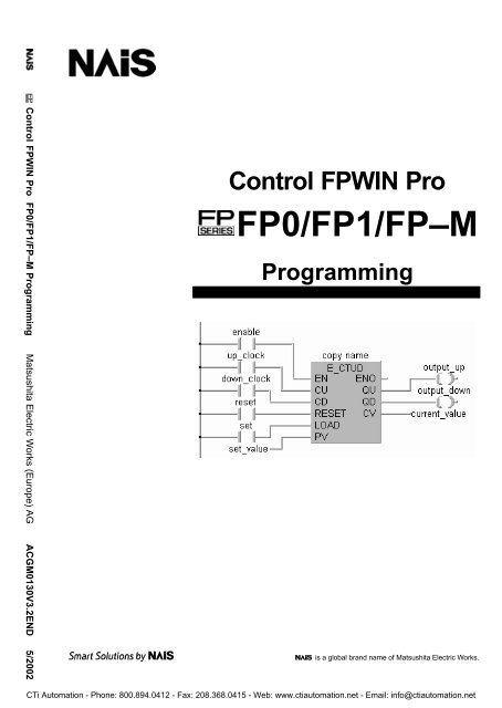
<strong>Control</strong> <strong>FPWIN</strong> <strong>Pro</strong> FP0/FP1/FP–M <strong>Pro</strong>gramming Matsushita Electric Works (Europe) AG ACGM0130V3.2END 5/2002<br />
<strong>Control</strong> <strong>FPWIN</strong> <strong>Pro</strong><br />
FP0/FP1/FP–M<br />
<strong>Pro</strong>gramming<br />
is a global brand name of Matsushita Electric Works.<br />
<strong>CTi</strong> <strong>Automation</strong> - Phone: 800.894.0412 - Fax: 208.368.0415 - Web: www.ctiautomation.net - Email: info@ctiautomation.net
BEFORE BEGINNING<br />
This manual and everything described in it are copyrighted. You may not copy this<br />
manual, in whole or part, without written consent of Matsushita Electric Works<br />
(Europe) AG.<br />
Matsushita Electric Works (Europe) AG pursues a policy of continuous improvement<br />
of the design and performance of its products, therefore, we reserve the right to<br />
change the manual/product without notice. In no event will Matsushita Electric Works<br />
(Europe) AG be liable for direct, special, incidental, or consequential damage<br />
resulting from any defect in the product or its documentation, even if advised of the<br />
possibility of such damages.<br />
LIMITED WARRANTY<br />
If physical defects caused by distribution are found, Matsushita Electric Works<br />
(Europe) AG will replace/repair the product free of charge. Exceptions include:<br />
When physical defects are due to different usage/treatment of the<br />
product other than described in the manual.<br />
When physical defects are due to defective equipment other than the<br />
distributed product.<br />
When physical defects are due to modifications/repairs by someone<br />
other than Matsushita Electric Works (Europe) AG.<br />
When physical defects are due to natural disasters.<br />
MS–DOS and Windows are registered trademarks of Microsoft Corporation.<br />
IBM Personal Computer AT is registered trademark of the International Business<br />
Machines Corporation.<br />
<strong>CTi</strong> <strong>Automation</strong> - Phone: 800.894.0412 - Fax: 208.368.0415 - Web: www.ctiautomation.net - Email: info@ctiautomation.net
Important Symbols<br />
The following symbols are used in this manual:<br />
!<br />
Whenever the warning triangle is used, especially important<br />
safety instructions are given. If they are not adhered to, the<br />
results could be:<br />
•personal injury and/or<br />
•significant damage to instruments or their contents,<br />
e.g. data<br />
A Note contains important additional information or indicates that you<br />
should proceed with caution.<br />
Example An Example contains an illustrative example of the previous text section.<br />
<strong>CTi</strong> <strong>Automation</strong> - Phone: 800.894.0412 - Fax: 208.368.0415 - Web: www.ctiautomation.net - Email: info@ctiautomation.net
Table of Contents<br />
Part I<br />
Chapter 1 Basics<br />
1.1 Operands . . . . . . . . . . . . . . . . . . . . . . . . . . . . . . . . . . . . . . . . . . . . . . . . . . . . . . . . . . . . . . . 2<br />
1.1.1 Inputs/Outputs . . . . . . . . . . . . . . . . . . . . . . . . . . . . . . . . . . . . . . . . . . . . . . . . . . 2<br />
1.1.2 Internal Relays . . . . . . . . . . . . . . . . . . . . . . . . . . . . . . . . . . . . . . . . . . . . . . . . . . 2<br />
1.1.3 Special Internal Relays . . . . . . . . . . . . . . . . . . . . . . . . . . . . . . . . . . . . . . . . . . . 2<br />
1.1.4 Timers and Counters . . . . . . . . . . . . . . . . . . . . . . . . . . . . . . . . . . . . . . . . . . . . 3<br />
1.1.5 Data Registers (DT) . . . . . . . . . . . . . . . . . . . . . . . . . . . . . . . . . . . . . . . . . . . . . 3<br />
1.1.6 Special Data Registers (DT) . . . . . . . . . . . . . . . . . . . . . . . . . . . . . . . . . . . . . . 4<br />
1.1.7 File Registers (FL) . . . . . . . . . . . . . . . . . . . . . . . . . . . . . . . . . . . . . . . . . . . . . . . 4<br />
1.1.8 Link Relays and Registers (L/LD) . . . . . . . . . . . . . . . . . . . . . . . . . . . . . . . . . . 4<br />
1.2 Addresses . . . . . . . . . . . . . . . . . . . . . . . . . . . . . . . . . . . . . . . . . . . . . . . . . . . . . . . . . . . . . . 6<br />
1.2.1 Matsushita Addresses . . . . . . . . . . . . . . . . . . . . . . . . . . . . . . . . . . . . . . . . . . . 6<br />
1.2.2 IEC Addresses . . . . . . . . . . . . . . . . . . . . . . . . . . . . . . . . . . . . . . . . . . . . . . . . . . 7<br />
1.2.3 Specifying Relay Addresses . . . . . . . . . . . . . . . . . . . . . . . . . . . . . . . . . . . . . . 9<br />
1.2.4 Timer Contacts (T) and Counter Contacts (C) . . . . . . . . . . . . . . . . . . . . . . . 9<br />
1.2.5 External Input (X) and Output Relays (Y) . . . . . . . . . . . . . . . . . . . . . . . . . . . 9<br />
1.2.6 Word Representation of Relays (WX, WY, WR, and WL) . . . . . . . . . . . . . . 10<br />
1.3 Constants . . . . . . . . . . . . . . . . . . . . . . . . . . . . . . . . . . . . . . . . . . . . . . . . . . . . . . . . . . . . . . 11<br />
1.3.1 Decimal Constants . . . . . . . . . . . . . . . . . . . . . . . . . . . . . . . . . . . . . . . . . . . . . . 11<br />
1.3.2 Hexadecimal Constants . . . . . . . . . . . . . . . . . . . . . . . . . . . . . . . . . . . . . . . . . . 11<br />
1.3.3 BCD Constants . . . . . . . . . . . . . . . . . . . . . . . . . . . . . . . . . . . . . . . . . . . . . . . . . 11<br />
1.4 Data Types . . . . . . . . . . . . . . . . . . . . . . . . . . . . . . . . . . . . . . . . . . . . . . . . . . . . . . . . . . . . . 12<br />
1.4.1 BOOL . . . . . . . . . . . . . . . . . . . . . . . . . . . . . . . . . . . . . . . . . . . . . . . . . . . . . . . . . 12<br />
1.4.2 INTEGER . . . . . . . . . . . . . . . . . . . . . . . . . . . . . . . . . . . . . . . . . . . . . . . . . . . . . . 12<br />
1.4.3 DOUBLE INTEGER . . . . . . . . . . . . . . . . . . . . . . . . . . . . . . . . . . . . . . . . . . . . . 13<br />
1.4.4 STRING . . . . . . . . . . . . . . . . . . . . . . . . . . . . . . . . . . . . . . . . . . . . . . . . . . . . . . . 13<br />
1.4.5 WORD . . . . . . . . . . . . . . . . . . . . . . . . . . . . . . . . . . . . . . . . . . . . . . . . . . . . . . . . . 13<br />
1.4.6 DOUBLE WORD . . . . . . . . . . . . . . . . . . . . . . . . . . . . . . . . . . . . . . . . . . . . . . . . 13<br />
1.4.7 ARRAY . . . . . . . . . . . . . . . . . . . . . . . . . . . . . . . . . . . . . . . . . . . . . . . . . . . . . . . . 14<br />
1.4.8 TIME . . . . . . . . . . . . . . . . . . . . . . . . . . . . . . . . . . . . . . . . . . . . . . . . . . . . . . . . . . 18<br />
1.4.9 REAL . . . . . . . . . . . . . . . . . . . . . . . . . . . . . . . . . . . . . . . . . . . . . . . . . . . . . . . . . . 18<br />
1.5 NC_TOOL Library . . . . . . . . . . . . . . . . . . . . . . . . . . . . . . . . . . . . . . . . . . . . . . . . . . . . . . . 20<br />
i<br />
<strong>CTi</strong> <strong>Automation</strong> - Phone: 800.894.0412 - Fax: 208.368.0415 - Web: www.ctiautomation.net - Email: info@ctiautomation.net
Table of Contents <strong>FPWIN</strong> <strong>Pro</strong> <strong>Pro</strong>gramming<br />
Part II IEC Functions and Function Blocks<br />
Chapter 2 Conversion Functions<br />
(E_)BOOL_TO_INT BOOL to INTEGER . . . . . . . . . . . . . . . . . . . . . . . . . . . . . . . . . . . . 26<br />
(E_)BOOL_TO_DINT BOOL to DOUBLE INTEGER . . . . . . . . . . . . . . . . . . . . . . . . . . . 27<br />
(E_)BOOL_TO_WORD BOOL to WORD . . . . . . . . . . . . . . . . . . . . . . . . . . . . . . . . . . . . . . 28<br />
(E_)BOOL_TO_DWORD BOOL to DOUBLE WORD . . . . . . . . . . . . . . . . . . . . . . . . . . . . . 29<br />
(E_)BOOL_TO_STRING BOOL to STRING . . . . . . . . . . . . . . . . . . . . . . . . . . . . . . . . . . . . . 30<br />
(E_)INT_TO_BOOL INTEGER to BOOL . . . . . . . . . . . . . . . . . . . . . . . . . . . . . . . . . . . . 31<br />
(E_)INT_TO_DINT INTEGER to DOUBLE INTEGER . . . . . . . . . . . . . . . . . . . . . . . 32<br />
(E_)INT_TO_WORD INTEGER to WORD . . . . . . . . . . . . . . . . . . . . . . . . . . . . . . . . . . . 33<br />
(E_)INT_TO_DWORD INTEGER to DOUBLE WORD . . . . . . . . . . . . . . . . . . . . . . . . . . 34<br />
(E_)INT_TO_REAL INTEGER to REAL . . . . . . . . . . . . . . . . . . . . . . . . . . . . . . . . . . . . 35<br />
(E_)INT_TO_TIME INTEGER to TIME . . . . . . . . . . . . . . . . . . . . . . . . . . . . . . . . . . . . 36<br />
(E_)INT_TO_BCD INTEGER to BCD . . . . . . . . . . . . . . . . . . . . . . . . . . . . . . . . . . . . . 37<br />
(E_)INT_TO_STRING INTEGER to STRING . . . . . . . . . . . . . . . . . . . . . . . . . . . . . . . . . . 38<br />
(E_)DINT_TO_BOOL DOUBLE INTEGER to BOOL . . . . . . . . . . . . . . . . . . . . . . . . . . . 39<br />
(E_)DINT_TO_INT DOUBLE INTEGER to INTEGER . . . . . . . . . . . . . . . . . . . . . . . 40<br />
(E_)DINT_TO_WORD DOUBLE INTEGER to WORD . . . . . . . . . . . . . . . . . . . . . . . . . . 41<br />
(E_)DINT_TO_DWORD DOUBLE INTEGER to DOUBLE WORD . . . . . . . . . . . . . . . . . 42<br />
(E_)DINT_TO_TIME DOUBLE INTEGER to TIME . . . . . . . . . . . . . . . . . . . . . . . . . . . . 43<br />
(E_)DINT_TO_REAL DOUBLE INTEGER to REAL . . . . . . . . . . . . . . . . . . . . . . . . . . . 44<br />
(E_)DINT_TO_BCD DOUBLE INTEGER to BCD . . . . . . . . . . . . . . . . . . . . . . . . . . . . 45<br />
(E_)DINT_TO_STRING DOUBLE INTEGER to STRING . . . . . . . . . . . . . . . . . . . . . . . . . 46<br />
(E_)WORD_TO_BOOL WORD to BOOL . . . . . . . . . . . . . . . . . . . . . . . . . . . . . . . . . . . . . . 47<br />
(E_)WORD_TO_INT WORD to INTEGER . . . . . . . . . . . . . . . . . . . . . . . . . . . . . . . . . . . 48<br />
(E_)WORD_TO_DINT WORD to DOUBLE INTEGER . . . . . . . . . . . . . . . . . . . . . . . . . . 49<br />
(E_)WORD_TO_DWORD WORD to DOUBLE WORD . . . . . . . . . . . . . . . . . . . . . . . . . . . . . 50<br />
(E_)WORD_TO_TIME WORD to TIME . . . . . . . . . . . . . . . . . . . . . . . . . . . . . . . . . . . . . . . 51<br />
(E_)WORD_TO_STRING WORD to STRING . . . . . . . . . . . . . . . . . . . . . . . . . . . . . . . . . . . . 52<br />
(E_)DWORD_TO_BOOL DOUBLE WORD to BOOL . . . . . . . . . . . . . . . . . . . . . . . . . . . . . 53<br />
(E_)DWORD_TO_INT DOUBLE WORD to INTEGER . . . . . . . . . . . . . . . . . . . . . . . . . . 54<br />
(E_)DWORD_TO_DINT DOUBLE WORD to DOUBLE INTEGER . . . . . . . . . . . . . . . . . 55<br />
(E_)DWORD_TO_WORD DOUBLE WORD to WORD . . . . . . . . . . . . . . . . . . . . . . . . . . . . . 56<br />
(E_)DWORD_TO_TIME DOUBLE WORD to TIME . . . . . . . . . . . . . . . . . . . . . . . . . . . . . . 57<br />
(E_)DWORD_TO_STRINGDOUBLE WORD to STRING . . . . . . . . . . . . . . . . . . . . . . . . . . . 58<br />
(E_)REAL_TO_INT REAL to INTEGER . . . . . . . . . . . . . . . . . . . . . . . . . . . . . . . . . . . . 59<br />
(E_)REAL_TO_DINT REAL to DOUBLE INTEGER . . . . . . . . . . . . . . . . . . . . . . . . . . . 60<br />
ii<br />
<strong>CTi</strong> <strong>Automation</strong> - Phone: 800.894.0412 - Fax: 208.368.0415 - Web: www.ctiautomation.net - Email: info@ctiautomation.net
<strong>FPWIN</strong> <strong>Pro</strong> <strong>Pro</strong>gramming<br />
Table of Contents<br />
(E_)REAL_TO_TIME REAL to TIME . . . . . . . . . . . . . . . . . . . . . . . . . . . . . . . . . . . . . . . . 61<br />
(E_)REAL_TO_STRING REAL to STRING . . . . . . . . . . . . . . . . . . . . . . . . . . . . . . . . . . . . . 62<br />
(E_)TIME_TO_INT TIME to INTEGER . . . . . . . . . . . . . . . . . . . . . . . . . . . . . . . . . . . . 64<br />
(E_)TIME_TO_DINT TIME to DOUBLE INTEGER . . . . . . . . . . . . . . . . . . . . . . . . . . . . 65<br />
(E_)TIME_TO_WORD TIME to WORD . . . . . . . . . . . . . . . . . . . . . . . . . . . . . . . . . . . . . . . 66<br />
(E_)TIME_TO_DWORD TIME to DOUBLE WORD . . . . . . . . . . . . . . . . . . . . . . . . . . . . . . 67<br />
(E_)TIME_TO_REAL TIME to REAL . . . . . . . . . . . . . . . . . . . . . . . . . . . . . . . . . . . . . . . . 68<br />
(E_)TIME_TO_STRING TIME to STRING . . . . . . . . . . . . . . . . . . . . . . . . . . . . . . . . . . . . . . 69<br />
(E_)TRUNC_TO_INT Truncate (cut off) decimal digits of REAL input variable,<br />
convert to INTEGER . . . . . . . . . . . . . . . . . . . . . . . . . . . . . . . . . . . 70<br />
(E_)TRUNC_TO_DINT Truncate (cut off) decimal digits of REAL input variable,<br />
convert to DOUBLE INTEGER . . . . . . . . . . . . . . . . . . . . . . . . . . 71<br />
(E_)BCD_TO_INT BCD to INTEGER . . . . . . . . . . . . . . . . . . . . . . . . . . . . . . . . . . . . . 72<br />
(E_)BCD_TO_DINT BCD to DOUBLE INTEGER . . . . . . . . . . . . . . . . . . . . . . . . . . . . 73<br />
Chapter 3 Numerical Functions<br />
(E_)ABS Absolute value . . . . . . . . . . . . . . . . . . . . . . . . . . . . . . . . . . . . . . . . 76<br />
Chapter 4 Arithmetic Functions<br />
(E_)MOVE Move value to specified destination . . . . . . . . . . . . . . . . . . . . . . 78<br />
E_ADD Add . . . . . . . . . . . . . . . . . . . . . . . . . . . . . . . . . . . . . . . . . . . . . . . . . 79<br />
E_SUB Subtract . . . . . . . . . . . . . . . . . . . . . . . . . . . . . . . . . . . . . . . . . . . . . 80<br />
E_MUL Multiply . . . . . . . . . . . . . . . . . . . . . . . . . . . . . . . . . . . . . . . . . . . . . . 81<br />
E_DIV Divide . . . . . . . . . . . . . . . . . . . . . . . . . . . . . . . . . . . . . . . . . . . . . . . 82<br />
(E_)MOD Modular arithmetic division, remainder stored in<br />
output variable . . . . . . . . . . . . . . . . . . . . . . . . . . . . . . . . . . . . . . . . 83<br />
(E_)SQRT Square root . . . . . . . . . . . . . . . . . . . . . . . . . . . . . . . . . . . . . . . . . . 84<br />
(E_)SIN Sine . . . . . . . . . . . . . . . . . . . . . . . . . . . . . . . . . . . . . . . . . . . . . . . . . 85<br />
(E_)ASIN Arcsine . . . . . . . . . . . . . . . . . . . . . . . . . . . . . . . . . . . . . . . . . . . . . . 86<br />
(E_)COS Cosine . . . . . . . . . . . . . . . . . . . . . . . . . . . . . . . . . . . . . . . . . . . . . . . 87<br />
(E_)ACOS Arccosine . . . . . . . . . . . . . . . . . . . . . . . . . . . . . . . . . . . . . . . . . . . . 88<br />
(E_)TAN Tangent . . . . . . . . . . . . . . . . . . . . . . . . . . . . . . . . . . . . . . . . . . . . . . 89<br />
(E_)ATAN Arctangent . . . . . . . . . . . . . . . . . . . . . . . . . . . . . . . . . . . . . . . . . . . 90<br />
(E_)LN Natural logarithm . . . . . . . . . . . . . . . . . . . . . . . . . . . . . . . . . . . . . . 91<br />
(E_)LOG Logarithm . . . . . . . . . . . . . . . . . . . . . . . . . . . . . . . . . . . . . . . . . . . . 92<br />
(E_)EXP Exponent of input variable to base e . . . . . . . . . . . . . . . . . . . . . 93<br />
(E_)EXPT Raises 1st input variable by the power of the 2nd input<br />
variable . . . . . . . . . . . . . . . . . . . . . . . . . . . . . . . . . . . . . . . . . . . . . . 94<br />
iii<br />
<strong>CTi</strong> <strong>Automation</strong> - Phone: 800.894.0412 - Fax: 208.368.0415 - Web: www.ctiautomation.net - Email: info@ctiautomation.net
Table of Contents <strong>FPWIN</strong> <strong>Pro</strong> <strong>Pro</strong>gramming<br />
Chapter 5 <strong>Pro</strong>cess Data Type Functions<br />
(E_)ADD_TIME Add TIME . . . . . . . . . . . . . . . . . . . . . . . . . . . . . . . . . . . . . . . . . . . . 98<br />
(E_)SUB_TIME Subtract TIME . . . . . . . . . . . . . . . . . . . . . . . . . . . . . . . . . . . . . . . . 99<br />
(E_)MUL_TIME_INT Multiply TIME by INTEGER . . . . . . . . . . . . . . . . . . . . . . . . . . . . . 100<br />
(E_)MUL_TIME_DINT Multiply TIME by DOUBLE INTEGER . . . . . . . . . . . . . . . . . . . . 101<br />
(E_)MUL_TIME_REAL Multiply TIME by REAL . . . . . . . . . . . . . . . . . . . . . . . . . . . . . . . . 102<br />
(E_)DIV_TIME_INT Divide TIME by INTEGER . . . . . . . . . . . . . . . . . . . . . . . . . . . . . . 103<br />
(E_)DIV_TIME_DINT Divide TIME by DOUBLE INTEGER . . . . . . . . . . . . . . . . . . . . . 104<br />
(E_)DIV_TIME_REAL Divide TIME by REAL . . . . . . . . . . . . . . . . . . . . . . . . . . . . . . . . . . 105<br />
Chapter 6 Bitshift Functions<br />
(E_)SHL Shift bits to the left . . . . . . . . . . . . . . . . . . . . . . . . . . . . . . . . . . . . 108<br />
(E_)SHR Shift bits to the right . . . . . . . . . . . . . . . . . . . . . . . . . . . . . . . . . . . 109<br />
(E_)ROL Rotate bits to the left . . . . . . . . . . . . . . . . . . . . . . . . . . . . . . . . . . 110<br />
(E_)ROR Rotate bits to the right . . . . . . . . . . . . . . . . . . . . . . . . . . . . . . . . . 111<br />
Chapter 7 Bitwise Boolean Functions<br />
(E_)AND Logical AND operation . . . . . . . . . . . . . . . . . . . . . . . . . . . . . . . . . 114<br />
E_OR Logical OR operation . . . . . . . . . . . . . . . . . . . . . . . . . . . . . . . . . . 115<br />
E_XOR Exclusive OR operation . . . . . . . . . . . . . . . . . . . . . . . . . . . . . . . . 116<br />
(E_)NOT Bit inversion . . . . . . . . . . . . . . . . . . . . . . . . . . . . . . . . . . . . . . . . . . 117<br />
Chapter 8 Selection Functions<br />
(E_)MAX Maximum value . . . . . . . . . . . . . . . . . . . . . . . . . . . . . . . . . . . . . . . 120<br />
(E_)MIN Minimum value . . . . . . . . . . . . . . . . . . . . . . . . . . . . . . . . . . . . . . . 121<br />
(E_)LIMIT Limit value for input variable . . . . . . . . . . . . . . . . . . . . . . . . . . . . 122<br />
(E_)MUX Select value from multiple channels . . . . . . . . . . . . . . . . . . . . . . 123<br />
(E_)SEL Select value from one of two channels . . . . . . . . . . . . . . . . . . . 125<br />
iv<br />
<strong>CTi</strong> <strong>Automation</strong> - Phone: 800.894.0412 - Fax: 208.368.0415 - Web: www.ctiautomation.net - Email: info@ctiautomation.net
<strong>FPWIN</strong> <strong>Pro</strong> <strong>Pro</strong>gramming<br />
Chapter 9 Comparison Functions<br />
Table of Contents<br />
E_GT Greater than . . . . . . . . . . . . . . . . . . . . . . . . . . . . . . . . . . . . . . . . . . 128<br />
E_GE Greater than or equal to . . . . . . . . . . . . . . . . . . . . . . . . . . . . . . . . 129<br />
E_EQ Equal to . . . . . . . . . . . . . . . . . . . . . . . . . . . . . . . . . . . . . . . . . . . . . . 130<br />
E_LE Less than or equal to . . . . . . . . . . . . . . . . . . . . . . . . . . . . . . . . . . 131<br />
E_LT Less than . . . . . . . . . . . . . . . . . . . . . . . . . . . . . . . . . . . . . . . . . . . . 132<br />
E_NE Not equal . . . . . . . . . . . . . . . . . . . . . . . . . . . . . . . . . . . . . . . . . . . . 133<br />
Chapter 10 Bistable Function Blocks<br />
(E_)SR Set/reset . . . . . . . . . . . . . . . . . . . . . . . . . . . . . . . . . . . . . . . . . . . . . 136<br />
(E_)RS Reset/set . . . . . . . . . . . . . . . . . . . . . . . . . . . . . . . . . . . . . . . . . . . . 138<br />
Chapter 11 Edge Detection<br />
(E_)R_TRIG Rising edge trigger . . . . . . . . . . . . . . . . . . . . . . . . . . . . . . . . . . . . 142<br />
(E_)F_TRIG Falling edge trigger . . . . . . . . . . . . . . . . . . . . . . . . . . . . . . . . . . . . 143<br />
Chapter 12 Counter<br />
(E_)CTU Up counter . . . . . . . . . . . . . . . . . . . . . . . . . . . . . . . . . . . . . . . . . . . 146<br />
(E_)CTD Down counter . . . . . . . . . . . . . . . . . . . . . . . . . . . . . . . . . . . . . . . . . 148<br />
(E_)CTUD Up/down counter . . . . . . . . . . . . . . . . . . . . . . . . . . . . . . . . . . . . . . 150<br />
Chapter 13 Timer<br />
(E_)TP Timer with defined period . . . . . . . . . . . . . . . . . . . . . . . . . . . . . . . 154<br />
(E_)TON Timer with switch–on delay . . . . . . . . . . . . . . . . . . . . . . . . . . . . . 156<br />
(E_)TOF Timer with switch–off delay . . . . . . . . . . . . . . . . . . . . . . . . . . . . . 158<br />
v<br />
<strong>CTi</strong> <strong>Automation</strong> - Phone: 800.894.0412 - Fax: 208.368.0415 - Web: www.ctiautomation.net - Email: info@ctiautomation.net
Table of Contents <strong>FPWIN</strong> <strong>Pro</strong> <strong>Pro</strong>gramming<br />
Part III Matsushita Instructions<br />
Chapter 14 Counter, Timer Function Blocks<br />
CT_FB Counter . . . . . . . . . . . . . . . . . . . . . . . . . . . . . . . . . . . . . . . . . . . . . . 164<br />
TM_1ms_FB Timer for 1ms intervals . . . . . . . . . . . . . . . . . . . . . . . . . . . . . . . . . 167<br />
TM_10ms_FB Timer for 10ms intervals . . . . . . . . . . . . . . . . . . . . . . . . . . . . . . . . 170<br />
TM_100ms_FB Timer for 100ms intervals . . . . . . . . . . . . . . . . . . . . . . . . . . . . . . 173<br />
TM_1s_FB Timer for 1s intervals . . . . . . . . . . . . . . . . . . . . . . . . . . . . . . . . . . 176<br />
Chapter 15 Data Transfer Instructions<br />
F0_MV 16–bit data move . . . . . . . . . . . . . . . . . . . . . . . . . . . . . . . . . . . . . . 180<br />
F1_DMV 32–bit data move . . . . . . . . . . . . . . . . . . . . . . . . . . . . . . . . . . . . . . 181<br />
F2_MVN 16–bit data inversions and move . . . . . . . . . . . . . . . . . . . . . . . . 182<br />
F3_DMVN 32–bit data inversions and move . . . . . . . . . . . . . . . . . . . . . . . . 183<br />
F5_BTM Bit data move . . . . . . . . . . . . . . . . . . . . . . . . . . . . . . . . . . . . . . . . . 184<br />
F6_DGT Digit data move . . . . . . . . . . . . . . . . . . . . . . . . . . . . . . . . . . . . . . . 186<br />
F10_BKMV Block transfer . . . . . . . . . . . . . . . . . . . . . . . . . . . . . . . . . . . . . . . . . 189<br />
F11_COPY Block copy . . . . . . . . . . . . . . . . . . . . . . . . . . . . . . . . . . . . . . . . . . . 191<br />
F12_EPRD EEPROM read from memory . . . . . . . . . . . . . . . . . . . . . . . . . . . 193<br />
P13_EPWT EEPROM write to memory . . . . . . . . . . . . . . . . . . . . . . . . . . . . . 195<br />
F15_XCH 16–bit data exchange . . . . . . . . . . . . . . . . . . . . . . . . . . . . . . . . . . 197<br />
F16_DXCH 32–bit data exchange . . . . . . . . . . . . . . . . . . . . . . . . . . . . . . . . . . 198<br />
F17_SWAP Higher/lower byte in 16–bit data exchange . . . . . . . . . . . . . . . . 199<br />
F144_TRNS Serial communication (RS232C) . . . . . . . . . . . . . . . . . . . . . . . . 200<br />
F147_PR Parallel printout . . . . . . . . . . . . . . . . . . . . . . . . . . . . . . . . . . . . . . . 208<br />
Chapter 16 Arithmetic Instructions<br />
F20_ADD 16–bit addition . . . . . . . . . . . . . . . . . . . . . . . . . . . . . . . . . . . . . . . . 212<br />
F21_DADD 32–bit addition . . . . . . . . . . . . . . . . . . . . . . . . . . . . . . . . . . . . . . . . 213<br />
F22_ADD2 16–bit addition, destination can be specified . . . . . . . . . . . . . . 214<br />
F23_DADD2 32–bit addition, destination can be specified . . . . . . . . . . . . . . 215<br />
F40_BADD 4–digit BCD addition . . . . . . . . . . . . . . . . . . . . . . . . . . . . . . . . . . . 216<br />
F41_DBADD 8–digit BCD addition . . . . . . . . . . . . . . . . . . . . . . . . . . . . . . . . . . . 217<br />
F42_BADD2 4–digit BCD addition, destination can be specified . . . . . . . . . 218<br />
F43_DBADD2 8–digit BCD addition, destination can be specified . . . . . . . . . 219<br />
vi<br />
<strong>CTi</strong> <strong>Automation</strong> - Phone: 800.894.0412 - Fax: 208.368.0415 - Web: www.ctiautomation.net - Email: info@ctiautomation.net
<strong>FPWIN</strong> <strong>Pro</strong> <strong>Pro</strong>gramming<br />
Table of Contents<br />
F157_CADD Time addition . . . . . . . . . . . . . . . . . . . . . . . . . . . . . . . . . . . . . . . . . 220<br />
F25_SUB 16–bit subtraction . . . . . . . . . . . . . . . . . . . . . . . . . . . . . . . . . . . . . 222<br />
F26_DSUB 32–bit subtraction . . . . . . . . . . . . . . . . . . . . . . . . . . . . . . . . . . . . . 223<br />
F27_SUB2 16–bit subtraction, destination can be specified . . . . . . . . . . . . 224<br />
F28_DSUB2 32–bit subtraction, destination can be specified . . . . . . . . . . . . 225<br />
F45_BSUB 4–digit BCD subtraction . . . . . . . . . . . . . . . . . . . . . . . . . . . . . . . . 226<br />
F46_DBSUB 8–digit BCD subtraction . . . . . . . . . . . . . . . . . . . . . . . . . . . . . . . . 227<br />
F47_BSUB2 4–digit BCD subtraction, destination can be specified . . . . . . 228<br />
F48_DBSUB2 8–digit BCD subtraction, destination can be specified . . . . . . 229<br />
F158_CSUB Time subtraction . . . . . . . . . . . . . . . . . . . . . . . . . . . . . . . . . . . . . . 230<br />
F30_MUL 16–bit multiplication, destination can be specified . . . . . . . . . . 232<br />
F31_DMUL 32–bit multiplication, destination can be specified . . . . . . . . . . 234<br />
F50_BMUL 4–digit BCD multiplication, destination can be specified . . . . . 235<br />
F51_DBMUL 8–digit BCD multiplication, destination can be specified . . . . . 237<br />
F32_DIV 16–bit division, destination can be specified . . . . . . . . . . . . . . . 238<br />
F33_DDIV 32–bit division, destination can be specified . . . . . . . . . . . . . . . 240<br />
F52_BDIV 4–digit BCD division, destination can be specified . . . . . . . . . 242<br />
F53_DBDIV 8–digit BCD division, destination can be specified . . . . . . . . . 244<br />
F35_INC 16–bit increment . . . . . . . . . . . . . . . . . . . . . . . . . . . . . . . . . . . . . . 246<br />
F36_DINC 32–bit increment . . . . . . . . . . . . . . . . . . . . . . . . . . . . . . . . . . . . . . 247<br />
F55_BINC 4–digit BCD increment . . . . . . . . . . . . . . . . . . . . . . . . . . . . . . . . . 248<br />
F56_DBINC 8–digit BCD increment . . . . . . . . . . . . . . . . . . . . . . . . . . . . . . . . . 249<br />
F37_DEC 16–bit decrement . . . . . . . . . . . . . . . . . . . . . . . . . . . . . . . . . . . . . 250<br />
F38_DDEC 32–bit decrement . . . . . . . . . . . . . . . . . . . . . . . . . . . . . . . . . . . . . 251<br />
F57_BDEC 4–digit BCD decrement . . . . . . . . . . . . . . . . . . . . . . . . . . . . . . . . 252<br />
F58_DBDEC 8–digit BCD decrement . . . . . . . . . . . . . . . . . . . . . . . . . . . . . . . . 253<br />
F87_ABS 16–bit data absolute value . . . . . . . . . . . . . . . . . . . . . . . . . . . . . . 254<br />
F88_DABS 32–bit data absolute value . . . . . . . . . . . . . . . . . . . . . . . . . . . . . . 255<br />
Chapter 17 Data Comparison Instructions<br />
F60_CMP 16–bit data compare . . . . . . . . . . . . . . . . . . . . . . . . . . . . . . . . . . . 258<br />
F61_DCMP 32–bit data compare . . . . . . . . . . . . . . . . . . . . . . . . . . . . . . . . . . . 260<br />
F62_WIN 16–bit data band compare . . . . . . . . . . . . . . . . . . . . . . . . . . . . . . 262<br />
F63_DWIN 32–bit data band compare . . . . . . . . . . . . . . . . . . . . . . . . . . . . . . 264<br />
F64_BCMP Block data compare . . . . . . . . . . . . . . . . . . . . . . . . . . . . . . . . . . . 266<br />
vii<br />
<strong>CTi</strong> <strong>Automation</strong> - Phone: 800.894.0412 - Fax: 208.368.0415 - Web: www.ctiautomation.net - Email: info@ctiautomation.net
Table of Contents <strong>FPWIN</strong> <strong>Pro</strong> <strong>Pro</strong>gramming<br />
Chapter 18 Logic Operation Instructions<br />
F65_WAN 16–bit data AND . . . . . . . . . . . . . . . . . . . . . . . . . . . . . . . . . . . . . . 270<br />
F66_WOR 16–bit data OR . . . . . . . . . . . . . . . . . . . . . . . . . . . . . . . . . . . . . . . 272<br />
F67_XOR 16–bit data exclusive OR . . . . . . . . . . . . . . . . . . . . . . . . . . . . . . . 274<br />
F68_XNR 16–bit data exclusive NOR . . . . . . . . . . . . . . . . . . . . . . . . . . . . . 276<br />
Chapter 19 Data Shift and Rotate Instructions<br />
LSR Left shift register . . . . . . . . . . . . . . . . . . . . . . . . . . . . . . . . . . . . . . 280<br />
F100_SHR Right shift of 16–bit data in bit units . . . . . . . . . . . . . . . . . . . . . . 281<br />
F101_SHL Left shift of 16–bit data in bit units . . . . . . . . . . . . . . . . . . . . . . . 282<br />
F105_BSR Right shift of one hexadecimal digit (4 bits) of 16–bit data . . . 283<br />
F106_BSL Left shift of one hexadecimal digit (4 bits) of 16–bit data . . . . 284<br />
F110_WSHR Right shift of one word (16 bits) of 16–bit data range . . . . . . . 285<br />
F111_WSHL Left shift of one word (16 bits) of 16–bit data range . . . . . . . . 287<br />
F112_WBSR Right shift of one hex. digit (4 bits) of 16–bit data range . . . . 289<br />
F113_WBSL Left shift of one hex. digit (4 bits) of 16–bit data range . . . . . . 291<br />
F119_LRSR LEFT/RIGHT shift register . . . . . . . . . . . . . . . . . . . . . . . . . . . . . . 293<br />
F120_ROR 16–bit data right rotate . . . . . . . . . . . . . . . . . . . . . . . . . . . . . . . . . 295<br />
F121_ROL 16–bit data left rotate . . . . . . . . . . . . . . . . . . . . . . . . . . . . . . . . . . 297<br />
F122_RCR 16–bit data right rotate with carry–flag data . . . . . . . . . . . . . . . 299<br />
F123_RCL 16–bit data left rotate with carry–flag data . . . . . . . . . . . . . . . . 301<br />
Chapter 20 Data Conversion Instructions<br />
F70_BCC Block check code calculation . . . . . . . . . . . . . . . . . . . . . . . . . . . 304<br />
F71_HEX2A HEX → ASCII conversion . . . . . . . . . . . . . . . . . . . . . . . . . . . . . . 307<br />
F72_A2HEX ASCII → HEX conversion . . . . . . . . . . . . . . . . . . . . . . . . . . . . . . 310<br />
F73_BCD2A BCD → ASCII conversion . . . . . . . . . . . . . . . . . . . . . . . . . . . . . . 313<br />
F74_A2BCD ASCII → BCD conversion . . . . . . . . . . . . . . . . . . . . . . . . . . . . . . 316<br />
F75_BIN2A 16–bit BIN → ASCII conversion . . . . . . . . . . . . . . . . . . . . . . . . . 319<br />
F76_A2BIN ASCII → 16–bit BIN conversion . . . . . . . . . . . . . . . . . . . . . . . . . 322<br />
F77_DBIN2A 32–bit BIN → ASCII conversion . . . . . . . . . . . . . . . . . . . . . . . . . 325<br />
F78_DA2BIN ASCII → 32–bit BIN conversion . . . . . . . . . . . . . . . . . . . . . . . . . 328<br />
F80_BCD 16–bit decimal → 4–digit BCD conversion . . . . . . . . . . . . . . . . 331<br />
F81_BIN 4–digit BCD → 16–bit decimal conversion . . . . . . . . . . . . . . . . 333<br />
F82_DBCD 32–bit decimal → 8–digit BCD conversion . . . . . . . . . . . . . . . . 335<br />
F83_DBIN 32–bit decimal → 8–digit BCD conversion . . . . . . . . . . . . . . . . 337<br />
viii<br />
<strong>CTi</strong> <strong>Automation</strong> - Phone: 800.894.0412 - Fax: 208.368.0415 - Web: www.ctiautomation.net - Email: info@ctiautomation.net
<strong>FPWIN</strong> <strong>Pro</strong> <strong>Pro</strong>gramming<br />
Table of Contents<br />
F84_INV 16–bit data invert (one’s complement) . . . . . . . . . . . . . . . . . . . . 339<br />
F85_NEG 16–bit data two’s complement . . . . . . . . . . . . . . . . . . . . . . . . . . . 340<br />
F86_DNEG 32–bit data two’s complement . . . . . . . . . . . . . . . . . . . . . . . . . . . 341<br />
F89_EXT 16–bit data sign extension . . . . . . . . . . . . . . . . . . . . . . . . . . . . . . 342<br />
F90_DECO Decode hexadecimal –> bit state . . . . . . . . . . . . . . . . . . . . . . . . 344<br />
F91_SEGT 16–bit data 7–segment decode . . . . . . . . . . . . . . . . . . . . . . . . . . 346<br />
F92_ENCO Encode bit state –> hexadecimal . . . . . . . . . . . . . . . . . . . . . . . . 348<br />
F93_UNIT 16–bit data combine . . . . . . . . . . . . . . . . . . . . . . . . . . . . . . . . . . . 350<br />
F94_DIST 16–bit data distribution . . . . . . . . . . . . . . . . . . . . . . . . . . . . . . . . . 352<br />
F95_ASC Character → ASCII transfer . . . . . . . . . . . . . . . . . . . . . . . . . . . . 355<br />
F96_SRC Table data search (16–bit search) . . . . . . . . . . . . . . . . . . . . . . . 358<br />
F138_HMSS h:min:s → s conversion . . . . . . . . . . . . . . . . . . . . . . . . . . . . . . . . 360<br />
F139_SHMS s → h:min:s conversion . . . . . . . . . . . . . . . . . . . . . . . . . . . . . . . . 361<br />
F327_INT Floating point data → 16–bit integer data<br />
(the largest integer not exceeding the floating point data) . . . 362<br />
F328_DINT Floating point data → 32–bit integer data (the largest integer<br />
not exceeding the floating point data) . . . . . . . . . . . . . . . . . . . . 364<br />
F333_FINT Rounding the first decimal point down . . . . . . . . . . . . . . . . . . . . 366<br />
F334_FRINT Rounding the first decimal point off . . . . . . . . . . . . . . . . . . . . . . 368<br />
F335_FSIGN Floating point data sign changes<br />
(negative/positive conversion) . . . . . . . . . . . . . . . . . . . . . . . . . . . 370<br />
F337_RAD Conversion of angle units (Degrees → Radians) . . . . . . . . . . . 372<br />
F338_DEG Conversion of angle units (Radians → Degrees) . . . . . . . . . . . 374<br />
Chapter 21 Bit Manipulation Instructions<br />
F130_BTS 16–bit data bit set . . . . . . . . . . . . . . . . . . . . . . . . . . . . . . . . . . . . . 378<br />
F131_BTR 16–bit data bit reset . . . . . . . . . . . . . . . . . . . . . . . . . . . . . . . . . . . 379<br />
F132_BTI 16–bit data bit invert . . . . . . . . . . . . . . . . . . . . . . . . . . . . . . . . . . . 380<br />
F133_BTT 16–bit data test . . . . . . . . . . . . . . . . . . . . . . . . . . . . . . . . . . . . . . . 381<br />
F135_BCU Number of ON bits in 16–bit data . . . . . . . . . . . . . . . . . . . . . . . . 383<br />
F136_DBCU Number of ON bits in 32–bit data . . . . . . . . . . . . . . . . . . . . . . . . 384<br />
Chapter 22 <strong>Pro</strong>cess <strong>Control</strong> Instructions<br />
F355_PID PID processing instruction . . . . . . . . . . . . . . . . . . . . . . . . . . . . . . 386<br />
ix<br />
<strong>CTi</strong> <strong>Automation</strong> - Phone: 800.894.0412 - Fax: 208.368.0415 - Web: www.ctiautomation.net - Email: info@ctiautomation.net
Table of Contents <strong>FPWIN</strong> <strong>Pro</strong> <strong>Pro</strong>gramming<br />
Chapter 23 Timer Instructions<br />
TM_1s Timer for 1s intervals . . . . . . . . . . . . . . . . . . . . . . . . . . . . . . . . . . 394<br />
TM_100ms Timer for 100ms intervals . . . . . . . . . . . . . . . . . . . . . . . . . . . . . . 396<br />
TM_10ms Timer for 10ms intervals . . . . . . . . . . . . . . . . . . . . . . . . . . . . . . . . 398<br />
TM_1ms Timer for 1ms intervals . . . . . . . . . . . . . . . . . . . . . . . . . . . . . . . . . 400<br />
F137_STMR Auxiliary timer (sets the ON–delay timer for 0.01s units) . . . . 402<br />
F183_DSTM Special 32–bit timer . . . . . . . . . . . . . . . . . . . . . . . . . . . . . . . . . . . 403<br />
Chapter 24 Counter Instructions<br />
CT Counter . . . . . . . . . . . . . . . . . . . . . . . . . . . . . . . . . . . . . . . . . . . . . . 406<br />
F118_UDC UP/DOWN counter . . . . . . . . . . . . . . . . . . . . . . . . . . . . . . . . . . . . 409<br />
Chapter 25 High–Speed Counter Special Instructions<br />
F0_MV High–speed counter control . . . . . . . . . . . . . . . . . . . . . . . . . . . . . 412<br />
F162_HC0S High–speed counter output set . . . . . . . . . . . . . . . . . . . . . . . . . . 418<br />
F163_HC0R High–speed counter output reset . . . . . . . . . . . . . . . . . . . . . . . . 419<br />
F164_SPD0 Pulse output control; Pattern output control . . . . . . . . . . . . . . . 420<br />
F165_CAM0 Cam control . . . . . . . . . . . . . . . . . . . . . . . . . . . . . . . . . . . . . . . . . . 421<br />
F166_HC1S Sets Output of High–speed counter (4 Channels) . . . . . . . . . . 422<br />
F167_HC1R Resets Output of High–speed Counter (4 Channels) . . . . . . . 424<br />
F168_SPD1 Positioning pulse instruction . . . . . . . . . . . . . . . . . . . . . . . . . . . . 426<br />
F169_PLS Pulse width modulation >= 40 Hz . . . . . . . . . . . . . . . . . . . . . . . . 432<br />
F170_PWM Pulse width modulation . . . . . . . . . . . . . . . . . . . . . . . . . . . . . . . . 435<br />
Chapter 26 Basic Sequence Instructions<br />
DF Leading edge differential . . . . . . . . . . . . . . . . . . . . . . . . . . . . . . . 440<br />
DFN Trailing edge differential . . . . . . . . . . . . . . . . . . . . . . . . . . . . . . . . 441<br />
KEEP Keep output ON or OFF depending on input variables . . . . . . 442<br />
SET, RST Set, Reset . . . . . . . . . . . . . . . . . . . . . . . . . . . . . . . . . . . . . . . . . . . 443<br />
x<br />
<strong>CTi</strong> <strong>Automation</strong> - Phone: 800.894.0412 - Fax: 208.368.0415 - Web: www.ctiautomation.net - Email: info@ctiautomation.net
<strong>FPWIN</strong> <strong>Pro</strong> <strong>Pro</strong>gramming<br />
Chapter 27 <strong>Control</strong> Instructions<br />
Table of Contents<br />
MC Master control relay . . . . . . . . . . . . . . . . . . . . . . . . . . . . . . . . . . . 448<br />
MCE Master control relay end . . . . . . . . . . . . . . . . . . . . . . . . . . . . . . . 449<br />
JP Jump . . . . . . . . . . . . . . . . . . . . . . . . . . . . . . . . . . . . . . . . . . . . . . . . 450<br />
LOOP Loop . . . . . . . . . . . . . . . . . . . . . . . . . . . . . . . . . . . . . . . . . . . . . . . . 451<br />
LBL Label . . . . . . . . . . . . . . . . . . . . . . . . . . . . . . . . . . . . . . . . . . . . . . . . 452<br />
ICTL Interrupt control . . . . . . . . . . . . . . . . . . . . . . . . . . . . . . . . . . . . . . . 453<br />
Chapter 28 Special Instructions<br />
F140_STC Carry–flag set . . . . . . . . . . . . . . . . . . . . . . . . . . . . . . . . . . . . . . . . 456<br />
F141_CLC Carry–flag reset . . . . . . . . . . . . . . . . . . . . . . . . . . . . . . . . . . . . . . . 457<br />
F143_IORF Partial I/O update . . . . . . . . . . . . . . . . . . . . . . . . . . . . . . . . . . . . . 458<br />
F148_ERR Self–diagnostic error set . . . . . . . . . . . . . . . . . . . . . . . . . . . . . . . 460<br />
F149_MSG Message display . . . . . . . . . . . . . . . . . . . . . . . . . . . . . . . . . . . . . . 462<br />
Appendix A High–Speed Counter, Pulse and PWM Output<br />
A.1 High–Speed Counter, Pulse and PWM Output . . . . . . . . . . . . . . . . . . . . . . . . . . . . . . . 464<br />
A.1.1 High–speed counter function . . . . . . . . . . . . . . . . . . . . . . . . . . . . . . . . . . . . . . 464<br />
A.1.2 Pulse output function . . . . . . . . . . . . . . . . . . . . . . . . . . . . . . . . . . . . . . . . . . . . 464<br />
A.1.3 PWM output function . . . . . . . . . . . . . . . . . . . . . . . . . . . . . . . . . . . . . . . . . . . . 464<br />
A.2 Specifications and Restricted Items . . . . . . . . . . . . . . . . . . . . . . . . . . . . . . . . . . . . . . . . 466<br />
A.2.1 Specifications . . . . . . . . . . . . . . . . . . . . . . . . . . . . . . . . . . . . . . . . . . . . . . . . . . . 466<br />
A.2.2 Functions and Restrictions . . . . . . . . . . . . . . . . . . . . . . . . . . . . . . . . . . . . . . . . 467<br />
A.3 High–Speed Counter Function . . . . . . . . . . . . . . . . . . . . . . . . . . . . . . . . . . . . . . . . . . . . . 469<br />
A.3.1 Types of Input Modes . . . . . . . . . . . . . . . . . . . . . . . . . . . . . . . . . . . . . . . . . . . . 469<br />
A.3.2 I/O Allocation . . . . . . . . . . . . . . . . . . . . . . . . . . . . . . . . . . . . . . . . . . . . . . . . . . . 470<br />
A.4 Pulse Output Function . . . . . . . . . . . . . . . . . . . . . . . . . . . . . . . . . . . . . . . . . . . . . . . . . . . . 471<br />
A.4.1 SDT Variables . . . . . . . . . . . . . . . . . . . . . . . . . . . . . . . . . . . . . . . . . . . . . . . . . . 471<br />
A.4.2 Positioning Function F168 . . . . . . . . . . . . . . . . . . . . . . . . . . . . . . . . . . . . . . . . 471<br />
A.4.3 Pulse Output Function F169 . . . . . . . . . . . . . . . . . . . . . . . . . . . . . . . . . . . . . . 472<br />
A.4.4 High–Speed Counter <strong>Control</strong> Instruction F0_MV . . . . . . . . . . . . . . . . . . . . . 473<br />
A.4.5 Elapsed Value Change and Read Instruction F1_DMV . . . . . . . . . . . . . . . . 474<br />
xi<br />
<strong>CTi</strong> <strong>Automation</strong> - Phone: 800.894.0412 - Fax: 208.368.0415 - Web: www.ctiautomation.net - Email: info@ctiautomation.net
Table of Contents <strong>FPWIN</strong> <strong>Pro</strong> <strong>Pro</strong>gramming<br />
A.5 Sample <strong>Pro</strong>gram for Positioning <strong>Control</strong> . . . . . . . . . . . . . . . . . . . . . . . . . . . . . . . . . . . . 475<br />
A.5.1 Relative Value Positioning Operation (Plus Direction) . . . . . . . . . . . . . . . . . 476<br />
A.5.2 Relative Value Positioning Operation (Minus Direction) . . . . . . . . . . . . . . . 477<br />
A.5.3 Absolute Value Positioning Operation . . . . . . . . . . . . . . . . . . . . . . . . . . . . . . 478<br />
A.5.4 Home Return Operation (Minus Direction) . . . . . . . . . . . . . . . . . . . . . . . . . . 479<br />
A.5.5 Home Return Operation (Plus Direction) . . . . . . . . . . . . . . . . . . . . . . . . . . . . 480<br />
A.5.6 JOG Operation (Plus Direction) . . . . . . . . . . . . . . . . . . . . . . . . . . . . . . . . . . . 481<br />
A.5.7 JOG Operation (Minus Direction) . . . . . . . . . . . . . . . . . . . . . . . . . . . . . . . . . . 481<br />
A.5.8 Emergency Stop . . . . . . . . . . . . . . . . . . . . . . . . . . . . . . . . . . . . . . . . . . . . . . . . 482<br />
Appendix B Special Data Registers<br />
B.1 Special Data Registers FP0 . . . . . . . . . . . . . . . . . . . . . . . . . . . . . . . . . . . . . . . . . . . . . . . 484<br />
B.2 Special Data Registers FP–M/FP1 . . . . . . . . . . . . . . . . . . . . . . . . . . . . . . . . . . . . . . . . . 492<br />
Appendix C Special Internal Relays<br />
C.1 Special Internal Relays . . . . . . . . . . . . . . . . . . . . . . . . . . . . . . . . . . . . . . . . . . . . . . . . . . . 508<br />
Appendix D Relays, Memory Areas and Constants<br />
D.1 Relays . . . . . . . . . . . . . . . . . . . . . . . . . . . . . . . . . . . . . . . . . . . . . . . . . . . . . . . . . . . . . . . . . 514<br />
D.2 Memory Areas . . . . . . . . . . . . . . . . . . . . . . . . . . . . . . . . . . . . . . . . . . . . . . . . . . . . . . . . . . 516<br />
D.3 Constants . . . . . . . . . . . . . . . . . . . . . . . . . . . . . . . . . . . . . . . . . . . . . . . . . . . . . . . . . . . . . . 518<br />
Appendix E System Registers<br />
E.1 System Registers for FP0 . . . . . . . . . . . . . . . . . . . . . . . . . . . . . . . . . . . . . . . . . . . . . . . . . 522<br />
E.2 System Registers for FP–M/FP1 . . . . . . . . . . . . . . . . . . . . . . . . . . . . . . . . . . . . . . . . . . . 531<br />
Appendix F Glossary<br />
Index<br />
Record of Changes<br />
xii<br />
<strong>CTi</strong> <strong>Automation</strong> - Phone: 800.894.0412 - Fax: 208.368.0415 - Web: www.ctiautomation.net - Email: info@ctiautomation.net
Chapter 1<br />
Part I<br />
Basics<br />
<strong>CTi</strong> <strong>Automation</strong> - Phone: 800.894.0412 - Fax: 208.368.0415 - Web: www.ctiautomation.net - Email: info@ctiautomation.net
Basics<br />
1.1 Operands<br />
In <strong>FPWIN</strong> <strong>Pro</strong> the following operands are available:<br />
• in– and outputs (X/Y) as well as internal memory areas<br />
• internal relays<br />
• special internal relays<br />
• timers and counters<br />
• data registers<br />
• special data registers<br />
• file registers<br />
• link registers and relays<br />
<strong>FPWIN</strong> <strong>Pro</strong> <strong>Pro</strong>gramming<br />
The number of operands which are available depends on the PLC–type and its configuration. To<br />
see how many of the respective operands are available, see your hardware description.<br />
1.1.1 Inputs/Outputs<br />
The amount of inputs/outputs available depends on the PLC and unit type. Each input terminal<br />
corresponds to one input X, each output terminal corresponds to one output Y.<br />
In system register 20 you set whether an output can be used once or more during the program.<br />
Outputs which do not exist physically can be used like flags. These flags are<br />
non–holding, which means their contents will be lost, e.g. after a power<br />
failure.<br />
1.1.2 Internal Relays<br />
Internal Relays are memory areas where you can store interim results. Internal relays are treated<br />
like internal outputs.<br />
In system register no. 7 you define which internal relays are supposed to be holding/non–holding.<br />
Holding means that its values will be retained even after a power failure.<br />
The number of available internal relays depends on the PLC type (see hardware description of<br />
your PLC).<br />
1.1.3 Special Internal Relays<br />
Special internal relays are memory areas which are reserved for special PLC functions. They are<br />
automatically set/reset by the PLC and are used:<br />
• to indicate certain system states, e.g. errors<br />
2<br />
<strong>CTi</strong> <strong>Automation</strong> - Phone: 800.894.0412 - Fax: 208.368.0415 - Web: www.ctiautomation.net - Email: info@ctiautomation.net
<strong>FPWIN</strong> <strong>Pro</strong> <strong>Pro</strong>gramming 1.1 Operands<br />
• as an impulse generator<br />
• to initialize the system<br />
• as ON/OFF control flag under certain conditions<br />
such as when some flags get a certain status if data are ready for<br />
transmission in a PLC network.<br />
The number of special internal relays available depends on the PLC type (see hardware<br />
description of your PLC).<br />
Special internal relays can only be read.<br />
1.1.4 Timers and Counters<br />
Timers and Counters use one common memory and address area.<br />
Define in system registers 5 and 6 how the memory area is to be divided between timers and<br />
counters and which timers/counters are supposed to be holding or non–holding. Holding means<br />
that even after a power failure all data will be saved, which is not the case in non–holding registers.<br />
Entering a number in system register 5 means that the first counter is defined. All smaller numbers<br />
define timers.<br />
For example, if you enter zero, you define counters only. If you enter the highest value possible,<br />
you define timers only.<br />
In the default setting the holding area is defined by the start address of the counter area. This<br />
means all timers are holding and all counters are non–holding. You can of course customize this<br />
setting and set a higher value for the holding area, which means some of the timers, or if you<br />
prefer, all of them can be defined as holding.<br />
In addition to the timer/counter area, there is a memory area reserved for the set value (SV) and<br />
the elapsed value (EV) of each timer/counter contact. The size of both areas is 16 bits (WORD).<br />
In the SV and EV area one INTEGER value from 0 to 32,767 can be stored.<br />
Timer/Counter No. SV EV Relay<br />
TM0 SV0 EV0 T0<br />
.<br />
.<br />
.<br />
.<br />
.<br />
.<br />
TM99 SV99 EV99 T99<br />
CT100 SV100 EV100 C100<br />
.<br />
.<br />
.<br />
.<br />
.<br />
.<br />
.<br />
.<br />
.<br />
.<br />
.<br />
.<br />
.<br />
.<br />
.<br />
.<br />
.<br />
.<br />
While a timer or counter is being processed, the respective acual value can be read and under<br />
certain conditions be edited.<br />
After changing the settings in system register 5, do not forget to adjust the<br />
addresses of the timers/counters in your PLC program because they<br />
correspond to the TM/CT numbers.<br />
1.1.5 Data Registers (DT)<br />
Data registers have a width of 16 bits. You can use them, for example, to write and read<br />
constants/parameters. If an instruction requires 32 bits, two 16–bit data registers are used. If this<br />
3<br />
<strong>CTi</strong> <strong>Automation</strong> - Phone: 800.894.0412 - Fax: 208.368.0415 - Web: www.ctiautomation.net - Email: info@ctiautomation.net
Basics<br />
<strong>FPWIN</strong> <strong>Pro</strong> <strong>Pro</strong>gramming<br />
is the case, enter the address of the first data register with the prefix DDT instead of DT. The next<br />
data register (word) will be used automatically (see example 1.2.1).<br />
2nd word 1st word<br />
DT2 DT1<br />
32 bit data register<br />
Data registers can be holding or non–holding. Holding means that even after a power failure all<br />
data will be saved. Set the holding/non–holding areas in system register 8 by entering the start<br />
address of the holding area.<br />
The amount of data registers available depends on the PLC type (see hardware description).<br />
1.1.6 Special Data Registers (DT)<br />
Special data registers are like the special internal relays reserved for special functions and are<br />
in most cases set/reset by the PLC.<br />
The register has a width of 16 bits (data type = WORD). The amount of special data registers<br />
available depends on the PLC type (see hardware description).<br />
Most special data registers can only be read. Here some exceptions:<br />
• actual values of the high–speed counter (DT9044 and DT9045; for<br />
FP0–T32CP DT90044 and DT90045)<br />
• control flag of the high–speed counter DT9052 (DT90053 for FP0–T32CP)<br />
• real–time clock (DT9054 to DT9058; FP0–T32CP: DT90054 to DT90058)<br />
• interrupts and scan time (DT9027, DT9023–DT9024; FP0–T32CP:<br />
DT90027, DT90023–DT90024)...<br />
1.1.7 File Registers (FL)<br />
Some PLC types (see hardware description) provide additional data registers which can be used<br />
to increase the number of data registers. File registers are used in the same way as data registers.<br />
Set the holding/non–holding area in system register 9. Holding means that even after a power<br />
failure all data will be saved.<br />
1.1.8 Link Relays and Registers (L/LD)<br />
Link relays have a width of 1 bit (BOOL). In system registers 10–13 and 40–55, set the:<br />
• transmission area<br />
• amount of link relay words to be sent<br />
• holding/non–holding area<br />
Link registers have a width of 16 bits (WORD). In system registers 10–13 and 40–55, set the:<br />
4<br />
<strong>CTi</strong> <strong>Automation</strong> - Phone: 800.894.0412 - Fax: 208.368.0415 - Web: www.ctiautomation.net - Email: info@ctiautomation.net
<strong>FPWIN</strong> <strong>Pro</strong> <strong>Pro</strong>gramming 1.1 Operands<br />
• transmission area<br />
• amount of link relay words to be sent<br />
• holding/non–holding area<br />
5<br />
<strong>CTi</strong> <strong>Automation</strong> - Phone: 800.894.0412 - Fax: 208.368.0415 - Web: www.ctiautomation.net - Email: info@ctiautomation.net
Basics<br />
1.2 Addresses<br />
<strong>FPWIN</strong> <strong>Pro</strong> <strong>Pro</strong>gramming<br />
In the List of Global Variables, enter the physical address in the field “Address” for each global<br />
variable used in the PLC program.<br />
The operand and the address number are part of the address. In <strong>FPWIN</strong> <strong>Pro</strong> you can use either<br />
Matsushita and/or IEC addresses. The following abbreviations are used:<br />
Meaning Matsushita IEC<br />
Input X I<br />
Output Y Q<br />
Memory (internal memory area) R M0<br />
Timer relay T M1<br />
Counter relay C M2<br />
Set value SV M3<br />
Elapsed value EV M4<br />
Data register DT/DDT M5<br />
Link relay L M6<br />
Link register LD M7<br />
File register FL M8<br />
You find the register numbers (e.g. DT9000/DT90000) in your hardware description. The next two<br />
sections show how Matsushita and IEC addresses are composed.<br />
1.2.1 Matsushita Addresses<br />
A Matsushita address represents the hardware address of an in–/output, register, or counter.<br />
For example, the hardware address of the 1st input and the 4th output of a PLC is:<br />
• X0 (X = input, 0 = first relay)<br />
• Y3 (Y = output, 3 = fourth relay)<br />
Use the following Matsushita abbreviations for the memory areas. You find the register numbers<br />
in your hardware description.<br />
Memory Area Abbr. Example<br />
Memory (internal memory area) R R9000: self diagnostic error<br />
Timer relay T T200: timer relay no. 200<br />
(settings in system register 5+6)<br />
Counter relay C C100: counter relay no. 100<br />
(settings in system register 5+6)<br />
Set value SV SV200 (set value for counter relay 200)<br />
Elapsed value EV EV100 (elapsed value for timer relay 100)<br />
Data register DT DT9001/DT90001 (signals power failure)<br />
Link relay L L1270<br />
Link register LD LD255<br />
File register FL FL8188<br />
6<br />
<strong>CTi</strong> <strong>Automation</strong> - Phone: 800.894.0412 - Fax: 208.368.0415 - Web: www.ctiautomation.net - Email: info@ctiautomation.net
<strong>FPWIN</strong> <strong>Pro</strong> <strong>Pro</strong>gramming 1.2 Addresses<br />
1.2.2 IEC Addresses<br />
The composition of an IEC–1131 address depends on:<br />
• operand type<br />
• data type<br />
• slot no. of the unit (word address)<br />
• relay no. (bit address)<br />
• PLC type<br />
In– and Outputs are the most important components of a programmable logic controller (PLC).<br />
The PLC receives signals from the input relays and processes them in the PLC program. The<br />
results can either be stored or sent to the output relays, which means the PLC controls the<br />
outputs.<br />
A PLC provides special memory areas, in short “M”, to store interim results, for example.<br />
If you want to read the status of the input 1 of the first module and control the output 4 of the<br />
second module, for example, you need the physical address of each in–/output. Physical <strong>FPWIN</strong><br />
<strong>Pro</strong> addresses are composed of the per cent sign, an abbreviation for in–/output, an abbreviation<br />
for the data type and of the word and bit address:<br />
Example IEC address for an input<br />
Physical<br />
Address<br />
Input<br />
%IX0.0<br />
Data<br />
Type=BOOL<br />
Word Address<br />
Bit Address<br />
The per cent sign is the indicator of a physical address. “I” means input, “X”<br />
means data type BOOL. The first zero represents the word address (slot no.)<br />
and the second one the bit address. Note that counting starts with zero and that<br />
counting word and bit addresses differs among the PLC types.<br />
Each PLC provides internal memory areas (M) to store interim results, for<br />
example. When using internal memory areas such as data registers, do not<br />
forget the additional number (here 5) for the memory type:<br />
Example IEC address for an internal memory area<br />
%MW5.0<br />
Physical<br />
Address<br />
Internal<br />
Memory Area Data Memory<br />
Word Address<br />
Bit addresses do not have to be defined for data registers, counters, timers, or<br />
the set and actual values.<br />
According to IEC 1131, abbreviations for in– and output are “I” and “O”, respectively.<br />
Abbreviations for the memory areas are as follows:<br />
7<br />
<strong>CTi</strong> <strong>Automation</strong> - Phone: 800.894.0412 - Fax: 208.368.0415 - Web: www.ctiautomation.net - Email: info@ctiautomation.net
Basics<br />
Memory Type No. Example<br />
Internal Relay (R) 0 %MX0.900.0 = internal relay R9000<br />
Timer (T) 1 %MX1.200 = counter no. 200<br />
Counter (C) 2 %MX2.100 = counter no. 100<br />
Set Value counters/timers (SV) 3 %MW3.200 = set value of the counter no. 200<br />
Elapsed Value counters/timers (EV) 4 %MW4.100 = elapsed value of the timer no. 100<br />
Data Registers (DT, DDT) 5 %MW5.9001 = data register DT9001<br />
%MD5.90001 = 32–bit data register DDT90001<br />
<strong>FPWIN</strong> <strong>Pro</strong> <strong>Pro</strong>gramming<br />
Tables with hardware addresses can be found in the hardware description<br />
of your PLC.<br />
The following data types are available:<br />
Data Type Abbreviation Range of Values Data Width<br />
BOOL BOOL 0 (FALSE), 1 (TRUE) 1 bit<br />
INTEGER INT –32,768 to 32,768 16 bits<br />
DOUBLE INTEGER DINT –2,147,438,648 to 2,147,438,647 32 bits<br />
WORD WORD 0 to 65,535 16 bits<br />
DOUBLE WORD DWORD 0 to 4,294,987,295 32 bits<br />
TIME 16–bit TIME T#0.00s to T#327.67s 16 bits*<br />
TIME 32–bit TIME T#0,00s to T#21 474 836.47s 32 bits*<br />
REAL REAL –1,175494 x 10 –38 to –3,402823 x 10 –38 and<br />
1,175494 x 10 –38 to 3,402823 x 10 –38<br />
*depends on your PLC<br />
8<br />
<strong>CTi</strong> <strong>Automation</strong> - Phone: 800.894.0412 - Fax: 208.368.0415 - Web: www.ctiautomation.net - Email: info@ctiautomation.net<br />
32 bits<br />
Please take into account that not all data types can be used with each IEC<br />
command.<br />
Numbering of in–/output addresses depends on the type of PLC used (see respective hardware<br />
description). For FP0/FP1/FP–M the addresses are not serially numbered. Counting restarts<br />
with zero at the first output. Supposing you have one FP1–C24 with 16 inputs and 8 outputs, the<br />
resulting addresses are: for the input: %IX0.0 – %IX0.15, and for the output: %QX0.0 – %QX0.7.<br />
In other words the counting for the word and bit number begins at zero for the outputs.<br />
• Find the tables with all memory areas in your hardware description.<br />
• When using timers, counters, set/elapsed values, and data registers,<br />
the bit address does not have to be indicated.<br />
• You can also enter the register number (R9000, DT9001/90001) or the<br />
Matsushita address, e.g. “X0” (input 0), instead of the IEC address.
<strong>FPWIN</strong> <strong>Pro</strong> <strong>Pro</strong>gramming 1.2 Addresses<br />
1.2.3 Specifying Relay Addresses<br />
External input relay (X), external output relay (Y), internal relay (R), link relay (L) and pulse relay<br />
(P)The lowest digit for these relay’s adresses is expressed in hexadecimals and the second and<br />
higher digits are expressed in decimals as shown below.<br />
Example Configuration of external input relay (X)<br />
XF, XE, XD, XC, XB, XA, X9, X8, X7, X6, X5, X4, X3, X2, X1, X0<br />
X1F, . . . . . . . . . . . . . . . . . . . . . . . . . . . . . . . . . . . . . . . . . . . . , X10<br />
X2F, . . . . . . . . . . . . . . . . . . . . . . . . . . . . . . . . . . . . . . . . . . . . , X20<br />
................<br />
X510F, . . . . . . . . . . . . . . . . . . . . . . . . . . . . . . . . . . . . . . . . , X5100<br />
X511F, . . . . . . . . . . . . . . . . . . . . . . . . . . . . . . . . . . . . . . . . . , X5110<br />
9<br />
<strong>CTi</strong> <strong>Automation</strong> - Phone: 800.894.0412 - Fax: 208.368.0415 - Web: www.ctiautomation.net - Email: info@ctiautomation.net<br />
................<br />
1.2.4 Timer Contacts (T) and Counter Contacts (C)<br />
Addresses of timer contacts (T) and counter contacts (C) correspond to the TM and CT instruction<br />
numbers and depend on the PLC type.<br />
Decimal<br />
0, 1, 2 ...<br />
e.g. for FP2:<br />
T0, T1 . . . . . . . . . . . . . . . . . . . . . . . . . . . . . . . . . . . T2999<br />
C3000, C3001 . . . . . . . . . . . . . . . . . . . . . . . . . . . . C3072<br />
Since addresses for timer contacts (T) and counter contacts (C) correspond<br />
to the TM and CT instruction numbers, if the TM and CT instruction sharing<br />
is changed by system register 5, timer and counter contact sharing is also<br />
changed.<br />
1.2.5 External Input (X) and Output Relays (Y)<br />
• The external input relays available are those actually allocated for input<br />
use.<br />
• The external output relays actually allocated for output can be used for<br />
turning ON or OFF external devices. The other external output relays can<br />
be used in the same way as internal relays.<br />
• I/O allocation is based on the combination of I/O and intelligent modules<br />
installed.
Basics<br />
1.2.6 Word Representation of Relays (WX, WY, WR, and WL)<br />
<strong>FPWIN</strong> <strong>Pro</strong> <strong>Pro</strong>gramming<br />
The external input relay (X), external output relay (Y), internal relay (R) and link relay (L) can also<br />
be expressed in word format. The word format treats 16-bit relay groups as one word. The word<br />
expressions for these relays are word external input relay (WX), word external output relay (WY),<br />
word internal relay (WR) and word link relay (WL), respectively.<br />
Example Configuration of word external input relay (WX)<br />
WX0<br />
WX1<br />
WX12<br />
XF XEXDXCXBXA X9X8 X7 X6 X5 X4 X3 X2 X1 X0<br />
X1FX1EX1D X12X11X10<br />
X12FX12EX12D X122X121X120<br />
Since the contents of the word relay correspond to the state of its relays<br />
(components), if some relays are turned ON, the contents of the word<br />
change.<br />
10<br />
<strong>CTi</strong> <strong>Automation</strong> - Phone: 800.894.0412 - Fax: 208.368.0415 - Web: www.ctiautomation.net - Email: info@ctiautomation.net
<strong>FPWIN</strong> <strong>Pro</strong> <strong>Pro</strong>gramming 1.3 Constants<br />
1.3 Constants<br />
A constant represents a fixed value. Depending on the application, a constant can be used as<br />
a addend, multiplier, address, in–/output number, set value, etc.<br />
There are 3 types of constants:<br />
• decimal<br />
• hexadecimal<br />
• BCD<br />
1.3.1 Decimal Constants<br />
Decimal constants can have a width of either 16 or 32 bits.<br />
Range 16 bit: –32,768 to 32,768<br />
Range 32 bit: –2,147,483,648 to 2,147,483,648<br />
Constants are internally changed into 16–bit binary numbers including character bit and are<br />
processed as such. Simply enter the decimal number in your program.<br />
1.3.2 Hexadecimal Constants<br />
Hexadecimal constants occupy fewer digit positions than binary data. 16 bit constants can be<br />
represented by 4–digit, 32–bit constants by 8–digit hecadecimal constants.<br />
Range 16 bit: 8000 to 7FFF<br />
Range 32 bit: 80000000 to 7FFFFFFFF<br />
Enter e.g.: 16#7FFF for the hexadecimal value 7FFF in your program.<br />
1.3.3 BCD Constants<br />
BCD is the abbreviation for Binary Coded Decimal.<br />
Range 16 bit: 0 to 9999<br />
Range 32 bit: 0 to 99999999<br />
Enter BCD constants in the program either as:<br />
binary: 2#0001110011100101 or<br />
hexadecimal: 16#9999<br />
11<br />
<strong>CTi</strong> <strong>Automation</strong> - Phone: 800.894.0412 - Fax: 208.368.0415 - Web: www.ctiautomation.net - Email: info@ctiautomation.net
Basics<br />
1.4 Data Types<br />
<strong>FPWIN</strong> <strong>Pro</strong> provides elementary and user defined data types.<br />
Elementary data types<br />
<strong>FPWIN</strong> <strong>Pro</strong> <strong>Pro</strong>gramming<br />
Data Type Abbreviation Value Range Data<br />
Width<br />
BOOL BOOL 0 (FALSE) or 1 (TRUE) 1 bit<br />
INTEGER INT –32,768 to 32,768 16 bits<br />
DOUBLE INTEGER DINT –2,147,483,648 to 2,147,483,647 32 bits<br />
WORD WORD 0 to 65,535 16 bits<br />
DOUBLE WORD DWORD 0 to 4,294,967,295 32 bits<br />
TIME 16– bit TIME T#0,00s to T#327.67s 16 bits*<br />
TIME 32 –bit TIME T#0,00s to T#21 474 836,47s 32 bits*<br />
REAL REAL –1,175494 x 10 –38 to –3,402823 x 10 –38 and<br />
1,175494 x 10 –38 to 3,402823 x 10 –38<br />
12<br />
<strong>CTi</strong> <strong>Automation</strong> - Phone: 800.894.0412 - Fax: 208.368.0415 - Web: www.ctiautomation.net - Email: info@ctiautomation.net<br />
32 bits<br />
*depends on your PLC<br />
A data type has to be assigned to each variable.<br />
User defined data types<br />
We differentiate between array and Data Unit Types (DUT). An array consists of several<br />
elementary data types which are all of the same type. A DUT consists of several elementary data<br />
types but of different data types. Each represents a new data type.<br />
1.4.1 BOOL<br />
Variables of the data type BOOL are binary switches. They either have the status 0 or 1 and have<br />
a width of 1 bit.<br />
The status 0 corresponds to FALSE and means that the variable has the status OFF.<br />
The status 1 corresponds to TRUE and means that the variable has the status ON.<br />
The default initial value, e.g. for the variable declaration in the POU header or in the List of Global<br />
Variables = 0 (FALSE). In this case the variable has the status FALSE at the moment the PLC<br />
program starts. If it should be TRUE at the start, reset the initial value to TRUE.<br />
1.4.2 INTEGER<br />
Variables of the data type INTEGER are integral natural numbers (without comma) and in WORD<br />
format. The range for INTEGER values is –32,768 to 32,768 (decimal).<br />
The default intial value, e.g. for the variable declaration in the POU header or in the List of Global<br />
Variables = 0 (FALSE). You can enter INTEGER numbers in DEC, HEX– or BIN format:<br />
Decimal Hexadecimal Binary<br />
1,234 16#4D2 2#10011010010<br />
–1,234 16#FB2E 2#1111101100101110
<strong>FPWIN</strong> <strong>Pro</strong> <strong>Pro</strong>gramming 1.4 Data Types<br />
1.4.3 DOUBLE INTEGER<br />
Variables of the data type DOUBLE INTEGER are 32–bit natural numbers without commas and<br />
in DOUBLD WORD format. The range for INTEGER values is –2,147,483,648 and<br />
2,147,483,648 decimal.<br />
The default intial value, e.g. for the variable declaration in the POU header or in the List of Global<br />
Variables, = 0 (FALSE). You can enter DOUBLE INTEGER numbers in DEC, HEX– or BIN format:<br />
Decimal Hexadecimal Binary<br />
123,456,789 16#75BCD15 2#111010110111100110100010101<br />
–123,456,789 16#F8A432EB 2#1111100010100100001100101110<br />
1.4.4 STRING<br />
The data type STRING consists of a series, i.e. string, of ASCII characters. You can store a<br />
maximum of 255 characters in one string. Each character of the string is stored in a byte.<br />
• The data type STRING is only available for the FP–SIGMA, FP2/2SH,<br />
FP3 and FP10SH.<br />
• For the PLCs FP0, FP1 and FP–M you can only enter the data type<br />
STRING as a constant in the POU body (see F95_ASC of the<br />
Matsushita Library).<br />
• For detailed information, see Online Help in <strong>FPWIN</strong> <strong>Pro</strong>.<br />
1.4.5 WORD<br />
A variable of the data type WORD consists of 16 bits. The states of 16 in–/outputs can be<br />
represented by one word (WORD), for example.<br />
The default intial value, e.g. for the variable declaration in the POU header or in the List of Global<br />
Variables, = 0 (FALSE). Enter WORD values in (DEC), HEX– or BIN format:<br />
Decimal Hexadecimal Binary<br />
1,234 16#4D2 2#10011010010<br />
–1,234 16#FB2E 2#1111101100101110<br />
1.4.6 DOUBLE WORD<br />
A variable of the data type DOUBLE WORD consists of 32 bits. The states of 32 in–/outputs can<br />
be represented by one DOUBLE WORD, for example.<br />
The default intial value, e.g. for the variable declaration in the POU header or in the List of Global<br />
Variables, = 0 (FALSE). Enter numbers in (DEC), HEX– or BIN format:<br />
Decimal Hexadecimal Binary<br />
123,456,789 16#75BCD15 2#111010110111100110100010101<br />
–123,456,789 16#F8A432EB 2#1111100010100100001100101110<br />
13<br />
<strong>CTi</strong> <strong>Automation</strong> - Phone: 800.894.0412 - Fax: 208.368.0415 - Web: www.ctiautomation.net - Email: info@ctiautomation.net
Basics<br />
1.4.7 ARRAY<br />
<strong>FPWIN</strong> <strong>Pro</strong> <strong>Pro</strong>gramming<br />
An array is a combination of variables, all of which have the same data type. This combination<br />
represents a variable itself, and therefore it has to be declared. This means that in order to make<br />
an array available for the entire project, it has to be declared in the List of Global Variables. If an<br />
array is used within a POU only, declare it in the POU header only.<br />
Data types valid for arrays are:<br />
• BOOL<br />
• INT<br />
• DINT<br />
• WORD<br />
• DWORD<br />
• TIME<br />
• REAL<br />
Arrays may be:<br />
• 1–dimensional<br />
• 2–dimensional<br />
• 3–dimensional<br />
Example 1–dimensional ARRAY<br />
Declaration in the global variable list:<br />
Declare in the global variable list:<br />
• identifier (name for calling up the array in the program)<br />
• initial address where array is saved in the memory<br />
• number of elements and data type of an array<br />
• initial values of individual array elements and<br />
• comment<br />
The declared array can be imagined as follows:<br />
onedim_array[0]<br />
element 1<br />
onedim_array[2]<br />
element 3<br />
onedim_array[1] element 2<br />
onedim_array[14]<br />
element 15<br />
onedim_array[15] element 16<br />
14<br />
<strong>CTi</strong> <strong>Automation</strong> - Phone: 800.894.0412 - Fax: 208.368.0415 - Web: www.ctiautomation.net - Email: info@ctiautomation.net
<strong>FPWIN</strong> <strong>Pro</strong> <strong>Pro</strong>gramming 1.4 Data Types<br />
Initialize Arrays with Values<br />
The initialisation of arrays with values starts with the first array element<br />
(element 1) and ends with the last array element (element 16). The initialisation<br />
values are entered one after another into the field initial and are separated from<br />
each other by commas.<br />
If subsequent array elements are initialised with the same value, the<br />
abbreviated writing number(value) is possible.<br />
* number stands for the number of array elements<br />
* value stands for the initialisation value<br />
In the example, element 1 was initialised with value 1, element 2 with value 2<br />
etc.<br />
Use Array Elements in the <strong>Pro</strong>gram<br />
You may use a 1–dimensional array element by entering identifier[Var1].<br />
* identifier (name of the array, see field Identifier)<br />
* Var1 is a variable of the type INT or a constant which has to be located in the<br />
value range of the array declaration. For this example Var1 is assigned to the<br />
range 0...15<br />
In the example you call up the third array element (Element 3) with<br />
onedim_array[2]. If you wish to assign a value to this element in an IL program<br />
for example, you enter the following:<br />
LD current_temperature<br />
ST onedim_array[2]<br />
Addresses of Array Elements<br />
The array elements of the 1–dimensional array are subsequently saved in the<br />
PLC’s memory starting with element 1. This means for the example described<br />
above:<br />
Matsushita<br />
Address<br />
IEC–Address Array Element Array Element Name<br />
DTO %MW5.0 element 1 onedim_array(0)<br />
DT1 %MW5.1 element 2 onedim_array(1)<br />
DT2 %MW5.2 element 3 onedim_array(2)<br />
DT3 %MW5.3 element 4 onedim_array(3)<br />
DT4 %MW5.4 element 5 onedim_array(4)<br />
... ... ... ...<br />
DT13 %MW5.13 element 14 onedim_array(13)<br />
DT14 %MW5.14 element 15 onedim_array(14)<br />
DT15 %MW5.15 element 16 onedim_array(15)<br />
Example 2–dimensional ARRAY<br />
Declaration in the global variable list:<br />
15<br />
<strong>CTi</strong> <strong>Automation</strong> - Phone: 800.894.0412 - Fax: 208.368.0415 - Web: www.ctiautomation.net - Email: info@ctiautomation.net
Basics<br />
The declared array can be imagined as follows:<br />
twodim_array[3,1]<br />
element 1<br />
twodim_array[3,2]<br />
element 2<br />
twodim_array[4,6]<br />
element 12<br />
twodim_array[5,6]<br />
element 18<br />
<strong>FPWIN</strong> <strong>Pro</strong> <strong>Pro</strong>gramming<br />
Initialize arrays with values<br />
The initialisation of arrays with values starts with the first array element<br />
(element 1) and ends with the last array element (element 18). The initialisation<br />
values are entered one after another into the field initial and are separated from<br />
each other by commas.<br />
If subsequent array elements are initialised with the same value, the<br />
abbreviated writing number(value) is possible.<br />
* number stands for the number of array elements<br />
* value stands for the initialisation value<br />
In the example element 1 was initialised with the value FALSE, element 2 with<br />
the value TRUE and the remaining array elements are initialised with FALSE.<br />
Use array elements in the program<br />
You may use a 2–dimensional array element by entering identifier[Var1Var2].<br />
* identifier (name of the array, see field Identifier)<br />
* Var1 and Var2 are variables of the type INT or constants which have to be<br />
located in the value range of the array declaration. For this example Var1 is<br />
assigned to the range 3...5 and Var2 to the range 1...6.<br />
In the example you call up the element 12 with twodim_array[4,6]. If you wish to<br />
assign a value to this element in an IL program for example, you enter the<br />
following:<br />
LD current_temperature<br />
ST twodim_array[4,6]<br />
Addresses of array elements<br />
The array elements of the 2–dimensional array are subsequently saved in the<br />
PLC’s memory starting with element 1. The following storage occupation results<br />
for the example described above:<br />
Matsushita<br />
Address<br />
IEC–Address Array Element Array Element Name<br />
R0 %MX0.0.0 element 1 twodim_array[3,1]<br />
R1 %MX0.0.1 element 2 twodim_array[3,2]<br />
R2 %MX0.0.2 element 3 twodim_array[3,3]<br />
... ... ... ...<br />
R5 %MX0.0.5 element 6 twodim_array[3,6]<br />
R6 %MX0.0.6 element 7 twodim_array[4,1]<br />
16<br />
<strong>CTi</strong> <strong>Automation</strong> - Phone: 800.894.0412 - Fax: 208.368.0415 - Web: www.ctiautomation.net - Email: info@ctiautomation.net
<strong>FPWIN</strong> <strong>Pro</strong> <strong>Pro</strong>gramming 1.4 Data Types<br />
Matsushita<br />
Address<br />
IEC–Address Array Element Array Element Name<br />
R7 %MX0.0.7 element 8 twodim_array[4,2]<br />
... ... ... ...<br />
RF %MX0.0.15 element 16 twodim_array[5,4]<br />
R10 %MX0.1.0 element 17 twodim_array[5,5]<br />
R11 %MX0.1.1 element 18 twodim_array[5,6]<br />
Example 3–dimensional ARRAY<br />
Declaration in the global variable list:<br />
The declared array can be imagined as follows:<br />
threedim_array[–7,0,2]<br />
element 13<br />
threedim_array[–8,0,2]<br />
element 1<br />
threedim_array[–8,0,3]<br />
element 2<br />
threedim_array[1,0,4]<br />
element 111<br />
Initialize arrays with values<br />
The initialisation of arrays with values starts with the first array element<br />
(element 1) and ends with the last array element (element 120). The<br />
initialisation values are entered one after another into the field initial and are<br />
separated from each other by commas. If subsequent array elements are<br />
initialised with the same value, the abbreviated writing number(value) is<br />
possible.<br />
* number stands for the number of array elements<br />
* value stands for the initialisation value<br />
In the example all array elements were initialised with the value 123.<br />
Use array elements in the program<br />
Access to a 3–dimensional array is possible by entering<br />
identifier[Var1,Var2,Var3,Var4].<br />
* identifier is the name of the array, (see field Identifier)<br />
* Var1, Var 2 and Var3 are variables of the type INT or constants which have to<br />
be located in the value range of the array declaration (see field Type). For this<br />
example Var1 is assigned to the range 8...1 and Var2 to the range 0...3 and<br />
Var3 to the range 2...4.<br />
17<br />
<strong>CTi</strong> <strong>Automation</strong> - Phone: 800.894.0412 - Fax: 208.368.0415 - Web: www.ctiautomation.net - Email: info@ctiautomation.net
Basics<br />
1.4.8 TIME<br />
<strong>FPWIN</strong> <strong>Pro</strong> <strong>Pro</strong>gramming<br />
In the example you call up element 15 with threedim_array[–7,0,4]. If you wish<br />
to assign a value to this element in an IL program, for example, you enter the<br />
following:<br />
LD current_temperature<br />
ST threedim_array[–7,0,4]<br />
Addresses of array elements<br />
The array elements of the 3–dimensional array are subsequently saved in the<br />
PLC’s memory starting with element 1. The following storage occupation results<br />
for the example described above:<br />
Matsushita Address IEC–Address Array Element Array Element Name<br />
DT0 %MW5.0 element 1 threedim_array[–8,0,2]<br />
DT1 %MW5.1 element 2 threedim_array[–8,0,3]<br />
DT2 %MW5.2 element 3 threedim_array[–8,0,4]<br />
DT3 %MW5.3 element 4 threedim_array[–8,1,2]<br />
DT4 %MW5.4 element 5 threedim_array[–8,1,3]<br />
... ... ... ...<br />
DT10 %MW5.10 element 11 threedim_array[–8,3,3]<br />
DT11 %MW5.11 element 12 threedim_array[–8,3,4]<br />
DT12 %MW5.12 element 13 threedim_array[–7,0,2]<br />
DT13 %MW5.13 element 14 threedim_array[–7,0,3]<br />
... ... ... ...<br />
DT117 %MW5.117 element 118 threedim_array[1,3,2]<br />
DT118 %MW5.118 element 119 threedim_array[1,3,3]<br />
DT119 %MW5.119 element 120 threedim_array[1,3,4]<br />
For variables of the data type TIME(32 Bit), you can indicate an interval of 0,01 to 21 474 836,47<br />
seconds. The resolution amounts to 10ms.<br />
Default (32–bit) = T#0 (corresponds to 0 seconds)<br />
Example<br />
1.4.9 REAL<br />
Times with negative signs cannot be processed. T#–2s is e.g. interpreted as<br />
T#10m53s350ms.<br />
T#321,12s<br />
T#321120ms<br />
T#0,01s<br />
T#3d5h10m3s100ms<br />
Variables of the data type REAL are real numbers or floating point constants. The value range<br />
for REAL values is between –1,175494 x 10 –38 to –3,402823 x 10 –38 and 1,175494 x 10 –38 to<br />
18<br />
<strong>CTi</strong> <strong>Automation</strong> - Phone: 800.894.0412 - Fax: 208.368.0415 - Web: www.ctiautomation.net - Email: info@ctiautomation.net
<strong>FPWIN</strong> <strong>Pro</strong> <strong>Pro</strong>gramming 1.4 Data Types<br />
3,402823 x 10 –38 . The default for the initial value, e.g. for the variable declaration in the POU<br />
header or in the global variable list = 0.0 You can enter REAL values in the following format: [+–]<br />
Integer.Integer [(Ee) [+–] Integer]<br />
Example<br />
5.983e–7<br />
–33.876e12<br />
3.876e3<br />
0.000123<br />
123.0<br />
The REAL value always has to be entered with a decimal point (e.g. 123.0).<br />
19<br />
<strong>CTi</strong> <strong>Automation</strong> - Phone: 800.894.0412 - Fax: 208.368.0415 - Web: www.ctiautomation.net - Email: info@ctiautomation.net
Basics<br />
1.5 NC_TOOL Library<br />
<strong>FPWIN</strong> <strong>Pro</strong> <strong>Pro</strong>gramming<br />
The NC_TOOL Library contains advanced address, information and copy functions<br />
available for all PLCs to make programming easier. Below please find a selection of<br />
these functions. For more detailed information and examples, see Online help.<br />
!<br />
Name Function<br />
Address functions<br />
<strong>Pro</strong>gram can be adversely effected!<br />
These functions can cause substantial problems by<br />
accessing incorrect memory areas if they are not used<br />
in the sense they were meant for. Especially other<br />
parts of the program can be adversely effected.<br />
Adr_Of_Var_I Address of a variable at the input of a Matsushita function<br />
Adr_Of_Var_O Address of a variable at the output of a Matsushita function<br />
AdrLast_Of_Var_I Address of a variable at the input of a Matsushita function<br />
AdrLast_Of_Var_O Address of a variable at the output of a Matsushita function<br />
Adr_Of_VarOffs_I Address of a variable with offset at the input of a Matsushita function<br />
Adr_Of_VarOffs_O Address of a variable with offset at the output of a Matsushita function<br />
AdrDT_Of_Offs_I DT address from the address offset for the input of a Matsushita function<br />
AdrDT_Of_Offs_0 DT address from the address offset for the output of a Matsushita function<br />
AdrFL_Of_Offs_I FL address from the address offset for the input of a Matsushita function<br />
AdrFL_Of_Offs_O FL address from the address offset for the output of a Matsushita function<br />
Functions that yield information on variables<br />
(E_)AreaOffs_OfVar Yields memory area and address offset of a variable (with Enable)<br />
(E_)Is_AreaDT Yields TRUE if the memory area of a variable is a DT area (with Enable)<br />
(E_)Is_AreaFL Yields TRUE if the memory area of a variable is an FL area (with Enable)<br />
(E_)Size_Of_Var Yields the size of a variable in words (with Enable)<br />
(E_)Elem_OfArray1D Yields the number of elements in an array (with Enable)<br />
(E_)Elem_OfArray2D Yields the number of elements of the 1st and 2nd dimension of an array (with Enable)<br />
(E_)Elem_OfArray3D Yields the number of elements of the 1st, 2nd and 3rd dimension of an array (with Enable)<br />
Additional Copy Functions<br />
(E_)Any16_ToBool16 Copies ANY16 to a variable with 16 elements of the data type BOOL (with Enable)<br />
(E_)Bool16_ToAny16 Copies a variable with 16 elements of the data type BOOL to ANY16 (with Enable)<br />
(E_)Any32_ToBool32 Copies ANY32 to a variable with 32 elements of the data type BOOL (with Enable)<br />
(E_)Bool32_ToAny32 Copies a variable with 32 elements of the data type BOOL to ANY32 (with Enable)<br />
(E_)Any16_ToSpecDT Copies ANY16 to the special data register DT(9000+Offs) or DT(90000+Offs) (with Enable)<br />
(E_)SpecDT_ToAny16 Copies the special data register DT(9000+Offs) or DT(90000+Offs) to ANY16 (with Enable)<br />
(E_)Any32_ToSpecDT Copies ANY32 to the special data register DT(9000+Offs) or DT(90000+Offs) (with Enable)<br />
20<br />
<strong>CTi</strong> <strong>Automation</strong> - Phone: 800.894.0412 - Fax: 208.368.0415 - Web: www.ctiautomation.net - Email: info@ctiautomation.net
<strong>FPWIN</strong> <strong>Pro</strong> <strong>Pro</strong>gramming 1.5 NC_TOOL Library<br />
Name<br />
Function<br />
(E_)SpecDT_ToAny32 Copies the special data register DT(9000+Offs) or DT(90000+Offs) to ANY32 (with Enable)<br />
(E_)AreaOffs_ToVar Copies the content of an address specified by memory area and address offset to a variable<br />
(with Enable)<br />
(E_)Var_ToAreaOffs Copies the value of a variable to an address specified by memory area and address offset<br />
to a variable (with Enable)<br />
21<br />
<strong>CTi</strong> <strong>Automation</strong> - Phone: 800.894.0412 - Fax: 208.368.0415 - Web: www.ctiautomation.net - Email: info@ctiautomation.net
Basics<br />
<strong>FPWIN</strong> <strong>Pro</strong> <strong>Pro</strong>gramming<br />
22<br />
<strong>CTi</strong> <strong>Automation</strong> - Phone: 800.894.0412 - Fax: 208.368.0415 - Web: www.ctiautomation.net - Email: info@ctiautomation.net
Part II<br />
IEC Functions and Function Blocks<br />
<strong>CTi</strong> <strong>Automation</strong> - Phone: 800.894.0412 - Fax: 208.368.0415 - Web: www.ctiautomation.net - Email: info@ctiautomation.net
Part II<br />
<strong>FPWIN</strong> <strong>Pro</strong> <strong>Pro</strong>gramming<br />
IEC programming<br />
For information on IEC programming and its advantages, please refer to the First Steps<br />
and IEC presentations on the installation CD for <strong>FPWIN</strong> <strong>Pro</strong>.<br />
The difference between functions with and without enable<br />
Functions with an enable input and output are identified by the prefix E_.<br />
The ENO status (TRUE or FALSE) of the first Function (FUN) or the first function block<br />
(FB) determines whether it will be executed and whether their outputs will be written to<br />
or not .<br />
If a subsequent FUN or FB uses one of these outputs as an input, the compiler creates<br />
a temporary variable. Since other temporary variables can occupy this address, the<br />
value is undefined at this position if it has not been written to, i.e. if ENO is FALSE.<br />
To avoid this, make sure all FUNs or FBs in a network are executed only if the previous<br />
FUN/FB has been executed, too. The compiler simply checks that the subsequent FUN<br />
or FB has no EN input and that an AND Function is not involved.<br />
24<br />
<strong>CTi</strong> <strong>Automation</strong> - Phone: 800.894.0412 - Fax: 208.368.0415 - Web: www.ctiautomation.net - Email: info@ctiautomation.net
Chapter 2<br />
Conversion Functions<br />
<strong>CTi</strong> <strong>Automation</strong> - Phone: 800.894.0412 - Fax: 208.368.0415 - Web: www.ctiautomation.net - Email: info@ctiautomation.net
(E_)BOOL_TO_INT IEC Instructions<br />
(E_)BOOL_TO_INT<br />
Description BOOL_TO_INT converts a value of the data type BOOL into a value of the data<br />
type INT.<br />
Data types<br />
For the difference between the normal IEC function and the function with an enable<br />
input, see page 24. You can find an example for the “function with enable” in the<br />
Online Help.<br />
Data type I/O Function<br />
BOOL input input data type<br />
INT output converion result<br />
Example In this example the function is programmed in ladder diagram (LD) and structured<br />
text (ST). The same POU header is used for both programming languages. You<br />
can find an instruction list (IL) example in the online help.<br />
POU<br />
header<br />
In the POU header, all input and output variables are declared that are used for<br />
programming this function.<br />
This example uses variables. You may also use a constants for the input variables.<br />
Body The Boolean_value of the data type BOOL is converted into a value of the data type<br />
INTEGER. The converted value is written into INT_value.<br />
LD<br />
ST IF Boolean_value THEN<br />
BOOL to INTEGER<br />
INT_value:=BOOL_TO_INT(Boolean_value);<br />
END_IF;<br />
26<br />
<strong>CTi</strong> <strong>Automation</strong> - Phone: 800.894.0412 - Fax: 208.368.0415 - Web: www.ctiautomation.net - Email: info@ctiautomation.net
Conversion Functions<br />
(E_)BOOL_TO_DINT<br />
(E_)BOOL_TO_DINT<br />
Description BOOL_TO_DINT converts a value of the data type BOOL into a value of the data<br />
type DINT.<br />
Data types<br />
For the difference between the normal IEC function and the function with an enable<br />
input, see page 24. You can find an example for the “function with enable” in the<br />
Online Help.<br />
Data type I/O Function<br />
BOOL input input data type<br />
DINT output conversion result<br />
Example In this example the function is programmed in ladder diagram (LD) and structured<br />
text (ST). The same POU header is used for both programming languages. You<br />
can find an instruction list (IL) example in the online help.<br />
POU<br />
header<br />
In the POU header, all input and output variables are declared that are used for<br />
programming this function.<br />
This example uses variables. You may also use a constants for the input variables.<br />
Body The Boolean_value of the data type BOOL is converted into a DOUBLE INTEGER<br />
value. The converted value is written into DINT_value.<br />
LD<br />
ST IF Boolean_value THEN<br />
BOOL to DOUBLE INTEGER<br />
DINT_value:=BOOL_TO_DINT(Boolean_value);<br />
END_IF;<br />
27<br />
<strong>CTi</strong> <strong>Automation</strong> - Phone: 800.894.0412 - Fax: 208.368.0415 - Web: www.ctiautomation.net - Email: info@ctiautomation.net
(E_)BOOL_TO_WORD IEC Instructions<br />
(E_)BOOL_TO_WORD<br />
Description BOOL_TO_WORD converts a value of the data type BOOL into a value of the data<br />
type WORD.<br />
Data types<br />
For the difference between the normal IEC function and the function with an enable<br />
input, see page 24. You can find an example for the “function with enable” in the<br />
Online Help.<br />
Data type I/O Function<br />
BOOL input input data type<br />
WORD output conversion result<br />
Example In this example the function is programmed in ladder diagram (LD) and structured<br />
text (ST). The same POU header is used for both programming languages. You<br />
can find an instruction list (IL) example in the online help.<br />
POU<br />
header<br />
In the POU header, all input and output variables are declared that are used for<br />
programming this function.<br />
This example uses variables. You may also use a constants for the input variables.<br />
Body The Boolean_value of the data type BOOL is converted into a value of the data type<br />
WORD. The converted value is written into WORD_value.<br />
LD<br />
ST IF Boolean_value THEN<br />
BOOL to WORD<br />
WORD_value:=BOOL_TO_WORD(Boolean_value);<br />
END_IF;<br />
28<br />
<strong>CTi</strong> <strong>Automation</strong> - Phone: 800.894.0412 - Fax: 208.368.0415 - Web: www.ctiautomation.net - Email: info@ctiautomation.net
Conversion Functions<br />
(E_)BOOL_TO_DWORD<br />
(E_)BOOL_TO_DWORD<br />
Description BOOL_TO_DWORD converts a value of the data type BOOL into a value of the<br />
data type DWORD.<br />
Data types<br />
For the difference between the normal IEC function and the function with an enable<br />
input, see page 24. You can find an example for the “function with enable” in the<br />
Online Help.<br />
Data type I/O Function<br />
BOOL input input data type<br />
DWORD output conversion result<br />
Example In this example the function is programmed in ladder diagram (LD) and structured<br />
text (ST). The same POU header is used for both programming languages. You<br />
can find an instruction list (IL) example in the online help.<br />
POU<br />
header<br />
In the POU header, all input and output variables are declared that are used for<br />
programming this function.<br />
This example uses variables. You may also use a constants for the input variables.<br />
Body The Boolean_value of the data type BOOL is converted into a value of the data type<br />
DOUBLE INTEGER. The converted value is written into DWORD_value.<br />
LD<br />
ST IF Boolean_value THEN<br />
BOOL to DOUBLE WORD<br />
DWORD_value:=BOOL_TO_DWORD(Boolean_value);<br />
END_IF;<br />
29<br />
<strong>CTi</strong> <strong>Automation</strong> - Phone: 800.894.0412 - Fax: 208.368.0415 - Web: www.ctiautomation.net - Email: info@ctiautomation.net
(E_)BOOL_TO_STRING IEC Instructions<br />
(E_)BOOL_TO_STRING<br />
Description The function BOOL_TO_STRING converts a value of the data type BOOL to a<br />
value of the data type STRING[1]. The resulting string is represented by ’0’ or ’1’.<br />
Data types<br />
For the difference between the normal IEC function and the function with an enable<br />
input, see page 24. You can find an example for the “function with enable” in the<br />
Online Help.<br />
Data type I/O Function<br />
BOOL input input data type<br />
STRING output conversion result<br />
When using the data type STRING, make sure that the length of the result<br />
string is equal to or greater than the length of the source string.<br />
Example In this example the function BOOL_TO_STRING is programmed in ladder diagram<br />
(LD) and instruction list (IL). The same POU header is used for both programming<br />
languages.<br />
POU<br />
header<br />
In the POU header, all input and output variables are declared that are used for<br />
programming this function.<br />
The input variable input_value of the data type BOOL is intialized by the value<br />
TRUE. The output variable result_string is of the data type STRING[1]. It can store<br />
a maximum of one character. You can declare a character string that has more than<br />
one character, e.g. STRING[5]. From the 5 characters reserved, only 4 are used.<br />
Instead of using the variable input_value, you can write the constants TRUE or<br />
FALSE directly to the function’s input contact in the body.<br />
Body The input_value of the data type BOOL is converted into STRING[1]. The<br />
converted value is written to result_string. When the variable input_value = TRUE,<br />
result_string shows ’1’.<br />
LD<br />
IL<br />
BOOL to STRING<br />
30<br />
<strong>CTi</strong> <strong>Automation</strong> - Phone: 800.894.0412 - Fax: 208.368.0415 - Web: www.ctiautomation.net - Email: info@ctiautomation.net
Conversion Functions<br />
(E_)INT_TO_BOOL<br />
(E_)INT_TO_BOOL<br />
Description INT_TO_BOOL converts a value of the type INT into a value of the type BOOL.<br />
Data types<br />
For the difference between the normal IEC function and the function with an enable<br />
input, see page 24. You can find an example for the “function with enable” in the<br />
Online Help.<br />
Data type I/O Function<br />
INT input input data type<br />
BOOL output conversion result<br />
Example In this example the function is programmed in ladder diagram (LD) and structured<br />
text (ST). The same POU header is used for both programming languages. You<br />
can find an instruction list (IL) example in the online help.<br />
POU<br />
header<br />
In the POU header, all input and output variables are declared that are used for<br />
programming this function.<br />
This example uses variables. You may also use a constants for the input variables.<br />
Body INT_value (16 bit) of the data type INTEGER is converted into a Boolean value.<br />
The result is written into Boolean_value.<br />
LD<br />
INTEGER to BOOL<br />
ST Boolean_value:=INT_TO_BOOL(INT_value);<br />
If INT_value has the value 0, the conversion result will be 0 (FALSE), in any<br />
other case it will be 1 (TRUE).<br />
31<br />
<strong>CTi</strong> <strong>Automation</strong> - Phone: 800.894.0412 - Fax: 208.368.0415 - Web: www.ctiautomation.net - Email: info@ctiautomation.net
(E_)INT_TO_DINT IEC Instructions<br />
(E_)INT_TO_DINT<br />
Description INT_TO_DINT converts a value of the type INT into a value of the type DINT.<br />
Data types<br />
For the difference between the normal IEC function and the function with an enable<br />
input, see page 24. You can find an example for the “function with enable” in the<br />
Online Help.<br />
Data type I/O Function<br />
INT input input data type<br />
DINT output conversion result<br />
Example In this example the function is programmed in ladder diagram (LD) and structured<br />
text (ST). The same POU header is used for both programming languages. You<br />
can find an instruction list (IL) example in the online help.<br />
POU<br />
header<br />
In the POU header, all input and output variables are declared that are used for<br />
programming this function.<br />
In this example the input variable (INT_value) has been declared. However, you<br />
may enter a constant directly at the input contact of the function.<br />
Body INT_value of the data type INTEGER is converted into a value of the data type<br />
DOUBLE INTEGER. The result will be written into DINT_value<br />
LD<br />
INTEGER to DOUBLE INTEGER<br />
ST DINT_value:=INT_TO_DINT(INT_value);<br />
32<br />
<strong>CTi</strong> <strong>Automation</strong> - Phone: 800.894.0412 - Fax: 208.368.0415 - Web: www.ctiautomation.net - Email: info@ctiautomation.net
Conversion Functions<br />
(E_)INT_TO_WORD<br />
(E_)INT_TO_WORD<br />
Description INT_TO_WORD converts a value of the type INT into a value of the type WORD.<br />
Data types<br />
For the difference between the normal IEC function and the function with an enable<br />
input, see page 24. You can find an example for the “function with enable” in the<br />
Online Help.<br />
Data type I/O Function<br />
INT input input data type<br />
WORD output conversion result<br />
Example In this example the function is programmed in ladder diagram (LD) and structured<br />
text (ST). The same POU header is used for both programming languages. You<br />
can find an instruction list (IL) example in the online help.<br />
POU<br />
header<br />
In the POU header, all input and output variables are declared that are used for<br />
programming this function.<br />
This example uses variables. You may also use a constants for the input variables.<br />
Body INT_value of the data type INTEGER is converted into a value of the data type<br />
WORD. The result is written in WORD_value.<br />
LD<br />
INTEGER to WORD<br />
ST WORD_value:=INT_TO_WORD(INT_value);<br />
The bit combination of the input variable is assigned to the output variable.<br />
33<br />
<strong>CTi</strong> <strong>Automation</strong> - Phone: 800.894.0412 - Fax: 208.368.0415 - Web: www.ctiautomation.net - Email: info@ctiautomation.net
(E_)INT_TO_DWORD IEC Instructions<br />
(E_)INT_TO_DWORD<br />
Description INT_TO_DWORD converts a value of the type INT into a value of the type<br />
DWORD.<br />
Data types<br />
For the difference between the normal IEC function and the function with an enable<br />
input, see page 24. You can find an example for the “function with enable” in the<br />
Online Help.<br />
Data type I/O Function<br />
INT input input data type<br />
DWORD output conversion result<br />
Example In this example the function is programmed in ladder diagram (LD) and structured<br />
text (ST). The same POU header is used for both programming languages. You<br />
can find an instruction list (IL) example in the online help.<br />
POU<br />
header<br />
In the POU header, all input and output variables are declared that are used for<br />
programming this function.<br />
This example uses variables. You may also use a constant for the input variable.<br />
Body INT_value of the data type INTEGER is converted into a value of the data type<br />
DOUBLE WORD (32 bit). The result is written in DWORD_value.<br />
LD<br />
INTEGER to DOUBLE WORD<br />
ST DWORD_value:=INT_TO_DWORD(INT_value);<br />
34<br />
<strong>CTi</strong> <strong>Automation</strong> - Phone: 800.894.0412 - Fax: 208.368.0415 - Web: www.ctiautomation.net - Email: info@ctiautomation.net
Conversion Functions<br />
(E_)INT_TO_REAL<br />
(E_)INT_TO_REAL<br />
Description INT_TO_REAL converts a value of the data type INTEGER into a value of the data<br />
type REAL.<br />
Data types<br />
For the difference between the normal IEC function and the function with an enable<br />
input, see page 24. You can find an example for the “function with enable” in the<br />
Online Help.<br />
Data type I/O Function<br />
INT input input data type<br />
REAL output conversion result<br />
Example In this example the function is programmed in ladder diagram (LD) and structured<br />
text (ST). The same POU header is used for both programming languages. You<br />
can find an instruction list (IL) example in the online help.<br />
POU<br />
header<br />
In the POU header, all input and output variables are declared that are used for<br />
programming this function.<br />
This example uses variables. You may also use a constant for the input variable.<br />
Body INT_value of the data type INTEGER is converted into a value of the data type<br />
REAL.The converted value is stored in REAL_value.<br />
LD<br />
INTEGER to REAL<br />
ST REAL_value:=INT_TO_REAL(INT_value);<br />
35<br />
<strong>CTi</strong> <strong>Automation</strong> - Phone: 800.894.0412 - Fax: 208.368.0415 - Web: www.ctiautomation.net - Email: info@ctiautomation.net
(E_)INT_TO_TIME IEC Instructions<br />
(E_)INT_TO_TIME<br />
Description INT_TO_TIME converts a value of the type INT into a value of the type TIME. The<br />
resolution is 10ms, e.g. when the INTEGER value = 350, the TIME value =<br />
3s500ms.<br />
Data types<br />
For the difference between the normal IEC function and the function with an enable<br />
input, see page 24. You can find an example for the “function with enable” in the<br />
Online Help.<br />
Data type I/O Function<br />
INT input input data type<br />
TIME output conversion result<br />
Example In this example the function is programmed in ladder diagram (LD) and structured<br />
text (ST). The same POU header is used for both programming languages. You<br />
can find an instruction list (IL) example in the online help.<br />
POU<br />
header<br />
In the POU header, all input and output variables are declared that are used for<br />
programming this function.<br />
This example uses variables. You may also use a constant for the input variable.<br />
Body INT_value of the data type INTEGER is converted into a value of the data type<br />
TIME. The result will be written into the output variable time_value.<br />
LD<br />
INTEGER to TIME<br />
ST time_value:=INT_TO_TIME(INT_value);<br />
36<br />
<strong>CTi</strong> <strong>Automation</strong> - Phone: 800.894.0412 - Fax: 208.368.0415 - Web: www.ctiautomation.net - Email: info@ctiautomation.net
Conversion Functions<br />
(E_)INT_TO_BCD<br />
(E_)INT_TO_BCD<br />
Description INT_TO_BCD converts a binary value of the type INTEGER in a BCD value (binary<br />
coded decimal integer) of the type WORD in order to be able to output BCD values<br />
in word format.<br />
Data types<br />
For the difference between the normal IEC function and the function with an enable<br />
input, see page 24. You can find an example for the “function with enable” in the<br />
Online Help.<br />
Data type I/O Function<br />
INT input input data type<br />
WORD output conversion result<br />
Example In this example the function is programmed in ladder diagram (LD) and structured<br />
text (ST). The same POU header is used for both programming languages. You<br />
can find an instruction list (IL) example in the online help.<br />
POU<br />
header<br />
In the POU header, all input and output variables are declared that are used for<br />
programming this function.<br />
This example uses variables. You may also use a constant for the input variable.<br />
Body INT_value of the data type INTEGER is converted into a BCD value of the data type<br />
WORD. The converted value is written into BCD_value_16bit.<br />
LD<br />
INTEGER to BCD<br />
ST BCD_value_16bit:=INT_TO_BCD(INT_value);<br />
Since the output variable is of the type WORD and 16 bits wide, the value of<br />
the input variable should have a maximum of 4 decimal places and should<br />
thus be located between 0 and 9999.<br />
37<br />
<strong>CTi</strong> <strong>Automation</strong> - Phone: 800.894.0412 - Fax: 208.368.0415 - Web: www.ctiautomation.net - Email: info@ctiautomation.net
(E_)INT_TO_STRING IEC Instructions<br />
(E_)INT_TO_STRING<br />
Description The function INT_TO_STRING converts a value of the data type INT to a value of<br />
the data type STRING[6]. The resulting string is right justified within the range<br />
’–32768’ to ’32767’. The plus sign is omitted in the positive range. Leading zeros<br />
are filled with empty spaces (e.g. out of –12 of STRING ’ –12’).<br />
Data types<br />
For the difference between the normal IEC function and the function with an enable<br />
input, see page 24. You can find an example for the “function with enable” in the<br />
Online Help.<br />
Data type I/O Function<br />
INT input input data type<br />
STRING[6] output conversion result<br />
When using the data type STRING, make sure that the length of the result<br />
string is equal or greater than the length of the source string.<br />
Example In this example the function is programmed in ladder diagram (LD) and structured<br />
text (ST). The same POU header is used for both programming languages. You<br />
can find an instruction list (IL) example in the online help.<br />
POU<br />
header<br />
In the POU header, all input and output variables are declared that are used for<br />
programming this function.<br />
The input variable input_value of the data type INT is intialized by the value 1234.<br />
The output variable result_string is of the data type STRING[6]. It can store a maximum<br />
of 6 characters. Instead of using the variable input_value, you can enter a<br />
constant directly at the function’s input contact in the body.<br />
Body The input_value of the data type INT is converted into STRING[6]. The converted<br />
value is written to result_string. When the variable input_value = 1234,<br />
result_string shows ’ 1234’.<br />
LD<br />
INTEGER to STRING<br />
ST result_string:= INT_TO_STRING(input_value);<br />
38<br />
<strong>CTi</strong> <strong>Automation</strong> - Phone: 800.894.0412 - Fax: 208.368.0415 - Web: www.ctiautomation.net - Email: info@ctiautomation.net
Conversion Functions<br />
(E_)DINT_TO_BOOL<br />
(E_)DINT_TO_BOOL<br />
Description DINT_TO_BOOL converts a value of the data type DINT into a value of the data<br />
type BOOL.<br />
Data types<br />
For the difference between the normal IEC function and the function with an enable<br />
input, see page 24. You can find an example for the “function with enable” in the<br />
Online Help.<br />
Data type I/O Function<br />
DINT input input data type<br />
BOOL output conversion result<br />
Example In this example the function is programmed in ladder diagram (LD) and structured<br />
text (ST). The same POU header is used for both programming languages. You<br />
can find an instruction list (IL) example in the online help.<br />
POU<br />
header<br />
In the POU header, all input and output variables are declared that are used for<br />
programming this function.<br />
This example uses variables. You may also use a constant for the input variable.<br />
Body DINT_value of the data type DOUBLE INTEGER is converted into a value of the<br />
data type BOOL. The converted value in written in Boolean_value.<br />
LD<br />
DOUBLE INTEGER to BOOL<br />
ST Boolean_value:=DINT_TO_BOOL(DINT_value);<br />
If the variable DINT_value has the value 0, the conversion result = FALSE,<br />
in any other case it will be TRUE.<br />
39<br />
<strong>CTi</strong> <strong>Automation</strong> - Phone: 800.894.0412 - Fax: 208.368.0415 - Web: www.ctiautomation.net - Email: info@ctiautomation.net
(E_)DINT_TO_INT IEC Instructions<br />
(E_)DINT_TO_INT<br />
Description DINT_TO_INT converts a value of the data type DINT into a value of the data type<br />
INT.<br />
Data types<br />
For the difference between the normal IEC function and the function with an enable<br />
input, see page 24. You can find an example for the “function with enable” in the<br />
Online Help.<br />
Data type I/O Function<br />
DINT input input data type<br />
INT output conversion result<br />
Example In this example the function is programmed in ladder diagram (LD) and structured<br />
text (ST). The same POU header is used for both programming languages. You<br />
can find an instruction list (IL) example in the online help.<br />
POU<br />
header<br />
In the POU header, all input and output variables are declared that are used for<br />
programming this function.<br />
This example uses variables. You may also use a constant for the input variable.<br />
Body DINT_value of the data type DOUBLE INTEGER (32 bit) is converted into a value<br />
of the data type INTEGER (16 bit). The converted value is written in INT_value.<br />
LD<br />
DOUBLE INTEGER to INTEGER<br />
ST INT_value:=DINT_TO_INT(DINT_value);<br />
The value of the input variable should be between –32768 and 32767.<br />
40<br />
<strong>CTi</strong> <strong>Automation</strong> - Phone: 800.894.0412 - Fax: 208.368.0415 - Web: www.ctiautomation.net - Email: info@ctiautomation.net
Conversion Functions<br />
(E_)DINT_TO_WORD<br />
(E_)DINT_TO_WORD<br />
Description DINT_TO_WORD converts a value of the data type DINT into a value of the data<br />
type WORD.<br />
Data types<br />
For the difference between the normal IEC function and the function with an enable<br />
input, see page 24. You can find an example for the “function with enable” in the<br />
Online Help.<br />
Data type I/O Function<br />
DINT input input data type<br />
WORD output conversion result<br />
Example In this example the function is programmed in ladder diagram (LD) and structured<br />
text (ST). The same POU header is used for both programming languages. You<br />
can find an instruction list (IL) example in the online help.<br />
POU<br />
header<br />
In the POU header, all input and output variables are declared that are used for<br />
programming this function.<br />
This example uses variables. You may also use a constant for the input variable.<br />
Body DINT_value of the data type DOUBLE INTEGER (32 bit) is converted into a value<br />
of the data type WORD (16 bit). The converted value is written in WORD_value.<br />
LD<br />
DOUBLE INTEGER to WORD<br />
ST WORD_value:=DINT_TO_WORD(DINT_value);<br />
The first 16 bits of the input variable are assigned to the output variable.<br />
41<br />
<strong>CTi</strong> <strong>Automation</strong> - Phone: 800.894.0412 - Fax: 208.368.0415 - Web: www.ctiautomation.net - Email: info@ctiautomation.net
(E_)DINT_TO_DWORD IEC Instructions<br />
(E_)DINT_TO_DWORD<br />
Description DINT_TO_DWORD converts a value of the data type DINT into a value of the data<br />
type DWORD.<br />
Data types<br />
For the difference between the normal IEC function and the function with an enable<br />
input, see page 24. You can find an example for the “function with enable” in the<br />
Online Help.<br />
Data type I/O Function<br />
DINT input input data type<br />
DWORD output conversion result<br />
Example In this example the function is programmed in ladder diagram (LD) and structured<br />
text (ST). The same POU header is used for both programming languages. You<br />
can find an instruction list (IL) example in the online help.<br />
POU<br />
header<br />
In the POU header, all input and output variables are declared that are used for<br />
programming this function.<br />
This example uses variables. You may also use a constant for the input variable.<br />
Body DINT_value of the data type DOUBLE INTEGER is converted into a value of the<br />
data type DOUBLE WORD. The converted value is written in DWORD_value.<br />
LD<br />
DOUBLE INTEGER to DOUBLE WORD<br />
ST DWORD_value:=DINT_TO_DWORD(DINT_value);<br />
The combination of the input variable is assigned to the output variable.<br />
42<br />
<strong>CTi</strong> <strong>Automation</strong> - Phone: 800.894.0412 - Fax: 208.368.0415 - Web: www.ctiautomation.net - Email: info@ctiautomation.net
Conversion Functions<br />
(E_)DINT_TO_TIME<br />
(E_)DINT_TO_TIME<br />
Description DINT_TO_TIME converts a value of the data type DINT into a value of the data<br />
type TIME. A value of 1 corresponds to a time of 10ms, e.g. an input value of 123<br />
is converted to a TIME T#1s230.00ms.<br />
Data types<br />
For the difference between the normal IEC function and the function with an enable<br />
input, see page 24. You can find an example for the “function with enable” in the<br />
Online Help.<br />
Data type I/O Function<br />
DINT input input data type<br />
TIME output conversion result<br />
Example In this example the function is programmed in ladder diagram (LD) and structured<br />
text (ST). The same POU header is used for both programming languages. You<br />
can find an instruction list (IL) example in the online help.<br />
POU<br />
header<br />
In the POU header, all input and output variables are declared that are used for<br />
programming this function.<br />
This example uses variables. You may also use a constant for the input variable.<br />
Body DINT_value of the data type DOUBLE INTEGER is converted to value of the data<br />
type TIME. The result is written into the output variable time_value.<br />
LD<br />
DOUBLE INTEGER to TIME<br />
ST time_value:=DINT_TO_TIME(DINT_value);<br />
43<br />
<strong>CTi</strong> <strong>Automation</strong> - Phone: 800.894.0412 - Fax: 208.368.0415 - Web: www.ctiautomation.net - Email: info@ctiautomation.net
(E_)DINT_TO_REAL IEC Instructions<br />
(E_)DINT_TO_REAL<br />
Description DINT_TO_REAL converts a value of the data type DOUBLE INTEGER into a value<br />
of the data type REAL.<br />
Data types<br />
For the difference between the normal IEC function and the function with an enable<br />
input, see page 24. You can find an example for the “function with enable” in the<br />
Online Help.<br />
This function is only available for the FP0.<br />
Data type I/O Function<br />
DINT input input data type<br />
REAL output conversion result<br />
Example In this example the function DINT_TO_REAL is programmed in ladder diagram<br />
(LD) and instruction list (IL). The same POU header is used for both programming<br />
languages.<br />
POU<br />
header<br />
In the POU header, all input and output variables are declared that are used for<br />
programming this function.<br />
This example uses variables. You may also use a constant for the input variable.<br />
Body DINT_value of the data type DOUBLE INTEGER is converted into a value of the<br />
data type REAL. The converted value is stored in REAL_value.<br />
LD<br />
DOUBLE INTEGER to REAL<br />
ST REAL_value:=DINT_TO_REAL(DINT_value);<br />
44<br />
<strong>CTi</strong> <strong>Automation</strong> - Phone: 800.894.0412 - Fax: 208.368.0415 - Web: www.ctiautomation.net - Email: info@ctiautomation.net
Conversion Functions<br />
(E_)DINT_TO_BCD<br />
(E_)DINT_TO_BCD<br />
Description DINT_TO_BCD converts a value of the data type DINT into a BCD value of the data<br />
type DWORD.<br />
Data types<br />
For the difference between the normal IEC function and the function with an enable<br />
input, see page 24. You can find an example for the “function with enable” in the<br />
Online Help.<br />
Data type I/O Function<br />
DINT input input data type<br />
DWORD output conversion result<br />
Example In this example the function DINT_TO_BCD is programmed in ladder diagram (LD)<br />
and instruction list (IL). The same POU header is used for both programming<br />
languages.<br />
POU<br />
header<br />
In the POU header, all input and output variables are declared that are used for<br />
programming this function.<br />
This example uses variables. You may also use a constant for the input variable.<br />
Body DINT_value of the data type DOUBLE INTEGER is converted into a BCD value<br />
of the data type DOUBLE WORD. The converted value is written in<br />
BCD_value_32bit.<br />
LD<br />
DOUBLE INTEGER to BCD<br />
ST BCD_value_32bit:=DINT_TO_BCD(DINT_value);<br />
The value for the input variable should be between 0 and 99999999.<br />
45<br />
<strong>CTi</strong> <strong>Automation</strong> - Phone: 800.894.0412 - Fax: 208.368.0415 - Web: www.ctiautomation.net - Email: info@ctiautomation.net
(E_)DINT_TO_STRING IEC Instructions<br />
(E_)DINT_TO_STRING<br />
Description The function DINT_TO_STRING converts a value of the data type DINT to a value<br />
of the data type STRING[11]. The resulting string is right justified within the range<br />
’–2147483648’ to ’2147483647’. The plus sign is omitted in the positive range.<br />
Leading zeros are filled with empty spaces (e.g. out of –12 of STRING ’ –12’).<br />
Data types<br />
For the difference between the normal IEC function and the function with an enable<br />
input, see page 24. You can find an example for the “function with enable” in the<br />
Online Help.<br />
Data type I/O Function<br />
DINT input input data type<br />
STRING output conversion result<br />
When using the data type STRING, make sure that the length of the result<br />
string is equal or greater than the length of the source string.<br />
Example In this example the function is programmed in ladder diagram (LD) and structured<br />
text (ST). The same POU header is used for both programming languages. You<br />
can find an instruction list (IL) example in the online help.<br />
POU<br />
header<br />
In the POU header, all input and output variables are declared that are used for<br />
programming this function.<br />
The input variable input_value of the data type DINT is intialized by the value<br />
12345678. The output variable result_string is of the data type STRING[11]. It can<br />
store a maximum of 11 characters.<br />
Instead of using the variable input_value, you can enter a constant directly at the<br />
function’s input contact in the body.<br />
Body The input_value of the data type DINT is converted into STRING[11]. The<br />
converted value is written to result_string. When the variable input_value =<br />
12345678, result_string shows ’ 12345678’.<br />
LD<br />
DOUBLE INTEGER to STRING<br />
ST result_string:=DINT_TO_STRING(input_value);<br />
46<br />
<strong>CTi</strong> <strong>Automation</strong> - Phone: 800.894.0412 - Fax: 208.368.0415 - Web: www.ctiautomation.net - Email: info@ctiautomation.net
Conversion Functions<br />
(E_)WORD_TO_BOOL<br />
(E_)WORD_TO_BOOL<br />
Description WORD_TO_BOOL converts a value of the type WORD into a value of the type<br />
BOOL.<br />
Data types<br />
For the difference between the normal IEC function and the function with an enable<br />
input, see page 24. You can find an example for the “function with enable” in the<br />
Online Help.<br />
Data type I/O Function<br />
WORD input input data type<br />
BOOL output conversion result<br />
Example In this example the function is programmed in ladder diagram (LD) and structured<br />
text (ST). The same POU header is used for both programming languages. You<br />
can find an instruction list (IL) example in the online help.<br />
POU<br />
header<br />
In the POU header, all input and output variables are declared that are used for<br />
programming this function.<br />
This example uses variables. You may also use a constant for the input variable.<br />
Body WORD_value_16bit of the data type WORD is converted into a Boolean value (11–<br />
bit). The result will be written in Boolean_value.<br />
LD<br />
WORD to BOOL<br />
ST Boolean_value:=WORD_TO_BOOL(WORD_value);<br />
If the value of WORD_value = 0 (16#0000), the conversion result will be = 0<br />
(FALSE), in any other case = 1 (TRUE).<br />
47<br />
<strong>CTi</strong> <strong>Automation</strong> - Phone: 800.894.0412 - Fax: 208.368.0415 - Web: www.ctiautomation.net - Email: info@ctiautomation.net
(E_)WORD_TO_INT IEC Instructions<br />
(E_)WORD_TO_INT<br />
Description WORD_TO_INT converts a value of the type WORD into a value of the type INT.<br />
Data types<br />
For the difference between the normal IEC function and the function with an enable<br />
input, see page 24. You can find an example for the “function with enable” in the<br />
Online Help.<br />
Data type I/O Function<br />
WORD input input data type<br />
INT output conversion result<br />
Example In this example the function is programmed in ladder diagram (LD) and structured<br />
text (ST). The same POU header is used for both programming languages. You<br />
can find an instruction list (IL) example in the online help.<br />
POU<br />
header<br />
In the POU header, all input and output variables are declared that are used for<br />
programming this function.<br />
This example uses variables. You may also use a constantfor the input variable.<br />
Body WORD_value of the data type WORD is converted into a value of the data type<br />
INTEGER. The result will be written in INT_value.<br />
LD<br />
WORD to INTEGER<br />
ST INT_value:=WORD_TO_INT(WORD_value);<br />
The bit combination of WORD_value is assigned to INT_value.<br />
48<br />
<strong>CTi</strong> <strong>Automation</strong> - Phone: 800.894.0412 - Fax: 208.368.0415 - Web: www.ctiautomation.net - Email: info@ctiautomation.net
Conversion Functions<br />
(E_)WORD_TO_DINT<br />
(E_)WORD_TO_DINT<br />
Description WORD_TO_DINT converts a value of the type WORD into a value of the type<br />
DINT.<br />
Data types<br />
For the difference between the normal IEC function and the function with an enable<br />
input, see page 24. You can find an example for the “function with enable” in the<br />
Online Help.<br />
Data type I/O Function<br />
WORD input input data type<br />
DINT output conversion result<br />
Example In this example the function is programmed in ladder diagram (LD) and structured<br />
text (ST). The same POU header is used for both programming languages. You<br />
can find an instruction list (IL) example in the online help.<br />
POU<br />
header<br />
In the POU header, all input and output variables are declared that are used for<br />
programming this function.<br />
This example uses variables. You may also use a constant for the input variable.<br />
Body WORD_value of the data type WORD is converted into a value of the data type<br />
INTEGER. The result will be written in DINT_value.<br />
LD<br />
WORD to DOUBLE INTEGER<br />
ST DINT_value:=WORD_TO_DINT(WORD_value);<br />
49<br />
<strong>CTi</strong> <strong>Automation</strong> - Phone: 800.894.0412 - Fax: 208.368.0415 - Web: www.ctiautomation.net - Email: info@ctiautomation.net
(E_)WORD_TO_DWORD IEC Instructions<br />
(E_)WORD_TO_DWORD<br />
Description WORD_TO_DWORD converts a value of the type WORD into a value of the type<br />
DWORD.<br />
Data types<br />
For the difference between the normal IEC function and the function with an enable<br />
input, see page 24. You can find an example for the “function with enable” in the<br />
Online Help.<br />
Data type I/O Function<br />
WORD input input data type<br />
DWORD output conversion result<br />
Example In this example the function is programmed in ladder diagram (LD) and structured<br />
text (ST). The same POU header is used for both programming languages. You<br />
can find an instruction list (IL) example in the online help.<br />
POU<br />
header<br />
In the POU header, all input and output variables are declared that are used for<br />
programming this function.<br />
This example uses variables. You may also use a constant for the input variable.<br />
Body WORD_value of the data type WORD is converted into a value of the data type<br />
DOUBLE WORD. The result will be written in DWORD_value.<br />
LD<br />
WORD to DOUBLE WORD<br />
ST DWORD_value:=WORD_TO_DWORD(WORD_value);<br />
The bit combination of WORD_value is assigned to DWORD_value.<br />
50<br />
<strong>CTi</strong> <strong>Automation</strong> - Phone: 800.894.0412 - Fax: 208.368.0415 - Web: www.ctiautomation.net - Email: info@ctiautomation.net
Conversion Functions<br />
(E_)WORD_TO_TIME<br />
(E_)WORD_TO_TIME<br />
Description WORD_TO_TIME converts a value of the type WORD into a value of the type<br />
TIME.<br />
Data types<br />
For the difference between the normal IEC function and the function with an enable<br />
input, see page 24. You can find an example for the “function with enable” in the<br />
Online Help.<br />
Data type I/O Function<br />
WORD input input data type<br />
TIME output conversion result<br />
Example In this example the function is programmed in ladder diagram (LD) and structured<br />
text (ST). The same POU header is used for both programming languages. You<br />
can find an instruction list (IL) example in the online help.<br />
POU<br />
header<br />
input variable 12345 ⇒ output variable: T#123.45s or<br />
input variable 16#0012 ⇒ output variable: T#180ms<br />
In the POU header, all input and output variables are declared that are used for<br />
programming this function.<br />
This example uses variables. You may also use a constant for the input variable.<br />
Body WORD_value of the data type WORD (16–bit) is converted into a value of the data<br />
type TIME (16–bit). The result will be written into the output variable time_value.<br />
LD<br />
WORD to TIME<br />
ST time_value:=WORD_TO_TIME(WORD_value);<br />
51<br />
<strong>CTi</strong> <strong>Automation</strong> - Phone: 800.894.0412 - Fax: 208.368.0415 - Web: www.ctiautomation.net - Email: info@ctiautomation.net
(E_)WORD_TO_STRING IEC Instructions<br />
(E_)WORD_TO_STRING<br />
Description The function WORD_TO_STRING converts a value of the data type WORD to a<br />
value of the data type STRING[7]. In accordance with IEC–1131, the hexadecimal<br />
representation of the result string is ’16#xxxx’, whereby xxxx is the hexadecimal<br />
representation of the input value. Possible values for the result string are in the<br />
range from ’16#0000’ to ’16#FFFF’, whereby leading zeros are filled with the<br />
character zero.<br />
Data types<br />
For the difference between the normal IEC function and the function with an enable<br />
input, see page 24. You can find an example for the “function with enable” in the<br />
Online Help.<br />
Data type I/O Function<br />
WORD input input data type<br />
STRING output conversion result<br />
When using the data type STRING, make sure that the length of the result<br />
string is equal or greater than the length of the source string.<br />
Example In this example the function is programmed in ladder diagram (LD) and structured<br />
text (ST). The same POU header is used for both programming languages. You<br />
can find an instruction list (IL) example in the online help.<br />
POU<br />
header<br />
In the POU header, all input and output variables are declared that are used for<br />
programming this function.<br />
The input variable input_value of the data type WORD is intialized by the value<br />
16#AE4. The output variable result_string is of the data type STRING[7]. It can<br />
store a maximum of 7 characters.<br />
Instead of using the variable input_value, you can enter a constant directly at the<br />
function’s input contact in the body.<br />
Body The input_value of the data type WORD is converted into STRING[7]. The<br />
converted value is written to result_string. When the variable input_value =<br />
16#AE4, result_string shows ’16#0AE4’.<br />
LD<br />
WORD to STRING<br />
ST result_string:=WORD_TO_STRING(input_value);<br />
52<br />
<strong>CTi</strong> <strong>Automation</strong> - Phone: 800.894.0412 - Fax: 208.368.0415 - Web: www.ctiautomation.net - Email: info@ctiautomation.net
Conversion Functions<br />
(E_)DWORD_TO_BOOL<br />
(E_)DWORD_TO_BOOL<br />
Description DWORD_TO_BOOL converts a value of the data type DOUBLE WORD into a<br />
value of the data type BOOL.<br />
Data types<br />
For the difference between the normal IEC function and the function with an enable<br />
input, see page 24. You can find an example for the “function with enable” in the<br />
Online Help.<br />
Data type I/O Function<br />
DWORD input input data type<br />
BOOL output conversion result<br />
Example In this example the function is programmed in ladder diagram (LD) and structured<br />
text (ST). The same POU header is used for both programming languages. You<br />
can find an instruction list (IL) example in the online help.<br />
POU<br />
header<br />
In the POU header, all input and output variables are declared that are used for<br />
programming this function.<br />
This example uses variables. You may also use a constant for the input variable.<br />
Body DWORD_value of the data type DOUBLE WORD is converted into a Boolean<br />
value (1 bit). the converted value is written in Boolean_value.<br />
LD<br />
DOUBLE WORD to BOOL<br />
ST Boolean_value:=DWORD_TO_BOOL(DWORD_value);<br />
If the variable DWORD_value has the value 0 (16#00000000), the conversion<br />
result will be FALSE, in any other case it will be TRUE.<br />
53<br />
<strong>CTi</strong> <strong>Automation</strong> - Phone: 800.894.0412 - Fax: 208.368.0415 - Web: www.ctiautomation.net - Email: info@ctiautomation.net
(E_)DWORD_TO_INT IEC Instructions<br />
(E_)DWORD_TO_INT<br />
Description DWORD_TO_INT converts a value of the data type DWORD into a value of the<br />
data type INT.<br />
Data types<br />
For the difference between the normal IEC function and the function with an enable<br />
input, see page 24. You can find an example for the “function with enable” in the<br />
Online Help.<br />
Data type I/O Function<br />
DWORD input input data type<br />
INT output conversion result<br />
Example In this example the function is programmed in ladder diagram (LD) and structured<br />
text (ST). The same POU header is used for both programming languages. You<br />
can find an instruction list (IL) example in the online help.<br />
POU<br />
header<br />
In the POU header, all input and output variables are declared that are used for<br />
programming this function.<br />
This example uses variables. You may also use constants for the input variables.<br />
Body DWORD_value of the data type DOUBLE WORD (32–bit) is converted into an<br />
INTEGER value (16–bit). The converted value is written in INT_value.<br />
LD<br />
DOUBLE WORD to INTEGER<br />
ST INT_value:=DWORD_TO_INT(DWORD_value);<br />
The first 16 bits of the input variable are assigned to the output variable.<br />
54<br />
<strong>CTi</strong> <strong>Automation</strong> - Phone: 800.894.0412 - Fax: 208.368.0415 - Web: www.ctiautomation.net - Email: info@ctiautomation.net
Conversion Functions<br />
(E_)DWORD_TO_DINT<br />
(E_)DWORD_TO_DINT<br />
Description DWORD_TO_DINT converts a value of the data type DOUBLE WORD into a value<br />
of the data type DOUBLE INTEGER.<br />
Data types<br />
For the difference between the normal IEC function and the function with an enable<br />
input, see page 24. You can find an example for the “function with enable” in the<br />
Online Help.<br />
Data type I/O Function<br />
DWORD input input data type<br />
DINT output conversion result<br />
Example In this example the function is programmed in ladder diagram (LD) and structured<br />
text (ST). The same POU header is used for both programming languages. You<br />
can find an instruction list (IL) example in the online help.<br />
POU<br />
header<br />
In the POU header, all input and output variables are declared that are used for<br />
programming this function.<br />
This example uses variables. You may also use a constant for the input variable.<br />
Body DWORD_value of the data type DOUBLE WORD is converted into a DOUBLE<br />
INTEGER value. The converted value is written in DINT_value.<br />
LD<br />
DOUBLE WORD to DOUBLE INTEGER<br />
ST DINT_value:=DWORD_TO_DINT(DWORD_value);<br />
The bit combination of the input variable will be assigned to the output<br />
variable.<br />
55<br />
<strong>CTi</strong> <strong>Automation</strong> - Phone: 800.894.0412 - Fax: 208.368.0415 - Web: www.ctiautomation.net - Email: info@ctiautomation.net
(E_)DWORD_TO_WORD IEC Instructions<br />
(E_)DWORD_TO_WORD<br />
Description DWORD_TO_WORD converts a value of the data type DOUBLE WORD into a<br />
value of the data type WORD.<br />
Data types<br />
For the difference between the normal IEC function and the function with an enable<br />
input, see page 24. You can find an example for the “function with enable” in the<br />
Online Help.<br />
Data type I/O Function<br />
DWORD input input data type<br />
WORD output conversion result<br />
Example In this example the function is programmed in ladder diagram (LD) and structured<br />
text (ST). The same POU header is used for both programming languages. You<br />
can find an instruction list (IL) example in the online help.<br />
POU<br />
header<br />
In the POU header, all input and output variables are declared that are used for<br />
programming this function.<br />
This example uses variables. You may also use a constant for the input variable.<br />
Body DWORD_value of the data type DOUBLE WORD (32–bit) is converted into a value<br />
of the data type WORD (16–bit). The converted value is written in WORD_value.<br />
LD<br />
DOUBLE WORD to WORD<br />
ST WORD_value:=DWORD_TO_WORD(DWORD_value);<br />
The first 16 bits of the input variable are assigned to the output variable.<br />
56<br />
<strong>CTi</strong> <strong>Automation</strong> - Phone: 800.894.0412 - Fax: 208.368.0415 - Web: www.ctiautomation.net - Email: info@ctiautomation.net
Conversion Functions<br />
(E_)DWORD_TO_TIME<br />
(E_)DWORD_TO_TIME<br />
Description DWORD_TO_TIME converts a value of the data type DWORD into a value of the<br />
data type TIME. A value of 1 corresponds to a time of 10ms, e.g. the input value<br />
12345 (16#3039) is converted to a TIME T#2m3s450.00ms.<br />
Data types<br />
For the difference between the normal IEC function and the function with an enable<br />
input, see page 24. You can find an example for the “function with enable” in the<br />
Online Help.<br />
Data type I/O Function<br />
DWORD input input data type<br />
TIME output conversion result<br />
Example In this example the function is programmed in ladder diagram (LD) and structured<br />
text (ST). The same POU header is used for both programming languages. You<br />
can find an instruction list (IL) example in the online help.<br />
POU<br />
header<br />
In the POU header, all input and output variables are declared that are used for<br />
programming this function.<br />
This example uses variables. You may also use a constant for the input variable.<br />
Body DWORD_value of the data type DWORD (32 bits) is converted into a value of the<br />
data type TIME (16 bits). The result is written into the output variable time_value.<br />
LD<br />
DOUBLE WORD to TIME<br />
ST time_value:=DWORD_TO_TIME(DWORD_value);<br />
57<br />
<strong>CTi</strong> <strong>Automation</strong> - Phone: 800.894.0412 - Fax: 208.368.0415 - Web: www.ctiautomation.net - Email: info@ctiautomation.net
(E_)DWORD_TO_STRING IEC Instructions<br />
(E_)DWORD_TO_STRING<br />
Description The function DWORD_TO_STRING converts a value of the data type DWORD to<br />
a value of the data type STRING[11]. In accordance with IEC–1131, the<br />
hexadecimal representation of the result string is ’16#xxxxxxxx’, whereby<br />
xxxxxxxx is the hexadecimal representation of the input value. Possible values for<br />
the result string are in the range from ’16#00000000’ to ’16#FFFFFFFF’, whereby<br />
leading zeros are filled with the character zero.<br />
Data types<br />
For the difference between the normal IEC function and the function with an enable<br />
input, see page 24. You can find an example for the “function with enable” in the<br />
Online Help.<br />
Data type I/O Function<br />
DWORD input input data type<br />
STRING output conversion result<br />
When using the data type STRING, make sure that the length of the result<br />
string is equal or greater than the length of the source string.<br />
Example In this example the function is programmed in ladder diagram (LD) and structured<br />
text (ST). The same POU header is used for both programming languages. You<br />
can find an instruction list (IL) example in the online help.<br />
POU<br />
header<br />
In the POU header, all input and output variables are declared that are used for<br />
programming this function.<br />
The input variable input_value of the data type DWORD is intialized by the value<br />
16#3ABDE4. The output variable result_string is of the data type STRING[11]. It<br />
can store a maximum of 11 characters.<br />
Instead of using the variable input_value, you can enter a constant directly at the<br />
function’s input contact in the body.<br />
Body The input_value of the data type DWORD is converted into STRING[11]. The<br />
converted value is written to result_string. When the variable input_value =<br />
16#3ABDE4, result_string shows ’16#003ABDE4’.<br />
LD<br />
DOUBLE WORD to STRING<br />
ST result_string:=DWORD_TO_STRING(input_value);<br />
58<br />
<strong>CTi</strong> <strong>Automation</strong> - Phone: 800.894.0412 - Fax: 208.368.0415 - Web: www.ctiautomation.net - Email: info@ctiautomation.net
Conversion Functions<br />
(E_)REAL_TO_INT<br />
(E_)REAL_TO_INT<br />
Description REAL_TO_INT converts a value of the data type REAL into a value of the data type<br />
INTEGER.<br />
Data types<br />
For the difference between the normal IEC function and the function with an enable<br />
input, see page 24. You can find an example for the “function with enable” in the<br />
Online Help.<br />
This function is only available for the FP0.<br />
Data type I/O Function<br />
REAL input input data type<br />
INT output conversion result<br />
Example In this example the function is programmed in ladder diagram (LD) and structured<br />
text (ST). The same POU header is used for both programming languages. You<br />
can find an instruction list (IL) example in the online help.<br />
POU<br />
header<br />
In the POU header, all input and output variables are declared that are used for<br />
programming this function.<br />
This example uses variables. You may also use a constant for the input variable.<br />
Body REAL_value of the data type REAL is converted into a value of the data type<br />
INTEGER. The converted value is stored in INT_value.<br />
LD<br />
REAL to INTEGER<br />
ST INT_value:= REAL_TO_INT(REAL_value);<br />
59<br />
<strong>CTi</strong> <strong>Automation</strong> - Phone: 800.894.0412 - Fax: 208.368.0415 - Web: www.ctiautomation.net - Email: info@ctiautomation.net
(E_)REAL_TO_DINT IEC Instructions<br />
(E_)REAL_TO_DINT<br />
Description REAL_TO_DINT converts a value of the data type REAL into a value of the data<br />
type DOUBLE INTEGER.<br />
Data types<br />
For the difference between the normal IEC function and the function with an enable<br />
input, see page 24. You can find an example for the “function with enable” in the<br />
Online Help.<br />
This function is only available for the FP0.<br />
Data type I/O Function<br />
REAL input input data type<br />
DINT output conversion result<br />
Example In this example the function is programmed in ladder diagram (LD) and structured<br />
text (ST). The same POU header is used for both programming languages. You<br />
can find an instruction list (IL) example in the online help.<br />
POU<br />
header<br />
In the POU header, all input and output variables are declared that are used for<br />
programming this function.<br />
This example uses variables. You may also use a constant for the input variable.<br />
Body REAL_value of the data type REAL is converted into a value of the data type<br />
DOUBLE INTEGER. The converted value is stored in DINT_value.<br />
LD<br />
REAL to DOUBLE INTEGER<br />
ST DINT_value:= REAL_TO_DINT(REAL_value);<br />
60<br />
<strong>CTi</strong> <strong>Automation</strong> - Phone: 800.894.0412 - Fax: 208.368.0415 - Web: www.ctiautomation.net - Email: info@ctiautomation.net
Conversion Functions<br />
(E_)REAL_TO_TIME<br />
(E_)REAL_TO_TIME<br />
Description REAL_TO_TIME converts a value of the data type REAL to a value of the data time<br />
TIME. 10ms of the data type TIME correspond to 1.0 REAL unit, e.g. when REAL<br />
= 1.0, TIME = 10ms; when REAL = 100.0, TIME = 1s. The value of the data type<br />
real is rounded off to the nearest whole number for the conversion.<br />
Data types<br />
For the difference between the normal IEC function and the function with an enable<br />
input, see page 24. You can find an example for the “function with enable” in the<br />
Online Help.<br />
This function is only available for the FP0.<br />
Data type I/O Function<br />
REAL input input data type<br />
TIME output conversion result<br />
Example In this example the function is programmed in ladder diagram (LD) and structured<br />
text (ST). The same POU header is used for both programming languages. You<br />
can find an instruction list (IL) example in the online help.<br />
POU<br />
header<br />
In the POU header, all input and output variables are declared that are used for<br />
programming this function.<br />
Body By clicking on the view icon while in the online mode, you can see the result 0.00ms<br />
immediately. Since the value at the REAL input contact is less than 0.5, it is<br />
rounded down to 0.0.<br />
LD<br />
REAL to TIME<br />
ST result_time:= REAL_TO_TIME(0.499);<br />
61<br />
<strong>CTi</strong> <strong>Automation</strong> - Phone: 800.894.0412 - Fax: 208.368.0415 - Web: www.ctiautomation.net - Email: info@ctiautomation.net
(E_)REAL_TO_STRING IEC Instructions<br />
(E_)REAL_TO_STRING<br />
Description The function REAL_TO_STRING converts a value from the data type REAL into<br />
a value of the data type STRING[15], which has 7 spaces both before and after the<br />
decimal point. The resulting string is right justified within the range<br />
’–999999.0000000’ to ’9999999.0000000’. The plus sign is omitted in the positive<br />
range. Leading zeros are filled with empty spaces (e.g. out of –12.0 of STRING ’<br />
–12.0’).<br />
Data types<br />
For the difference between the normal IEC function and the function with an enable<br />
input, see page 24. You can find an example for the “function with enable” in the<br />
Online Help.<br />
This function is only available for the FP0.<br />
Data type I/O Function<br />
REAL input input data type<br />
STRING output conversion result<br />
• When using the data type STRING, make sure that the length of the<br />
result string is equal or greater than the length of the source string.<br />
• The function requires approximately 160 steps of program memory.<br />
For repeated use you should integrate it into a user function that is<br />
only stored once in the memory.<br />
Example In this example the function REAL_TO_STRING is programmed in ladder diagram<br />
(LD) and instruction list (IL). The same POU header is used for both programming<br />
languages.<br />
POU<br />
header<br />
In the POU header, all input and output variables are declared that are used for<br />
programming this function.<br />
The input variable input_value of the data type REAL is intialized by the value<br />
–123.4560166. The output variable result_string is of the data type STRING[15].<br />
It can store a maximum of 15 characters.<br />
Instead of using the variable input_value, you can enter a constant directly at the<br />
function’s input contact in the body.<br />
Body The input_value of the data type REAL is converted into STRING[15]. The<br />
converted value is written to result_string. When the variable input_value =<br />
123.4560166, result_string shows ’ –123.4560166’.<br />
LD<br />
REAL to STRING<br />
62<br />
<strong>CTi</strong> <strong>Automation</strong> - Phone: 800.894.0412 - Fax: 208.368.0415 - Web: www.ctiautomation.net - Email: info@ctiautomation.net
Conversion Functions<br />
IL<br />
(E_)REAL_TO_STRING<br />
63<br />
<strong>CTi</strong> <strong>Automation</strong> - Phone: 800.894.0412 - Fax: 208.368.0415 - Web: www.ctiautomation.net - Email: info@ctiautomation.net
(E_)TIME_TO_INT IEC Instructions<br />
(E_)TIME_TO_INT<br />
Description TIME_TO_INT converts a value of the type TIME into a value of the type INT.<br />
Data types<br />
For the difference between the normal IEC function and the function with an enable<br />
input, see page 24. You can find an example for the “function with enable” in the<br />
Online Help.<br />
Data type I/O Function<br />
TIME input input data type<br />
INT output conversion result<br />
Example In this example the function is programmed in ladder diagram (LD) and structured<br />
text (ST). The same POU header is used for both programming languages. You<br />
can find an instruction list (IL) example in the online help.<br />
POU<br />
header<br />
Input variable: T#12.34s ⇒ output variable: 1234<br />
In the POU header, all input and output variables are declared that are used for<br />
programming this function.<br />
This example uses variables. You may also use a constant for the input variable.<br />
Body Time_value of the data type TIME is converted into a value of the data type<br />
INTEGER. The result will be written into the output variable<br />
INT_value.<br />
LD<br />
TIME to INTEGER<br />
ST INT_value:=TIME_TO_INT(time_value);<br />
64<br />
<strong>CTi</strong> <strong>Automation</strong> - Phone: 800.894.0412 - Fax: 208.368.0415 - Web: www.ctiautomation.net - Email: info@ctiautomation.net
Conversion Functions<br />
(E_)TIME_TO_DINT<br />
(E_)TIME_TO_DINT<br />
Description TIME_TO_DINT converts a value of the data type TIME into a value of the data<br />
type DINT. The time 10ms corresponds to the value 1, e.g. an input value of<br />
T#1m0s is converted to the value 6000.<br />
Data types<br />
For the difference between the normal IEC function and the function with an enable<br />
input, see page 24. You can find an example for the “function with enable” in the<br />
Online Help.<br />
Data type I/O Function<br />
TIME input input data type<br />
DINT output conversion result<br />
Example In this example the function is programmed in ladder diagram (LD) and structured<br />
text (ST). The same POU header is used for both programming languages. You<br />
can find an instruction list (IL) example in the online help.<br />
POU<br />
header<br />
In the POU header, all input and output variables are declared that are used for<br />
programming this function.<br />
This example uses variables. You may also use a constant for the input variable.<br />
Body time_value of the data type TIME is converted to value of the data type DOUBLE<br />
INTEGER. The result is written into the output variable DINT_value.<br />
LD<br />
TIME to DOUBLE INTEGER<br />
ST DINT_value:=TIME_TO_DINT(time_value);<br />
65<br />
<strong>CTi</strong> <strong>Automation</strong> - Phone: 800.894.0412 - Fax: 208.368.0415 - Web: www.ctiautomation.net - Email: info@ctiautomation.net
(E_)TIME_TO_WORD IEC Instructions<br />
(E_)TIME_TO_WORD<br />
Description TIME_TO_WORD converts a value of the type TIME into a value of the type<br />
WORD.<br />
Data types<br />
For the difference between the normal IEC function and the function with an enable<br />
input, see page 24. You can find an example for the “function with enable” in the<br />
Online Help.<br />
Data type I/O Function<br />
TIME input input data type<br />
WORD output conversion result<br />
Example In this example the function is programmed in ladder diagram (LD) and structured<br />
text (ST). The same POU header is used for both programming languages. You<br />
can find an instruction list (IL) example in the online help.<br />
POU<br />
header<br />
TIME to WORD<br />
Input variable: T#12.34s ⇒ output variable: 1234 or<br />
input variable: T#1.00s ⇒ output variable: 16#0064<br />
In the POU header, all input and output variables are declared that are used for<br />
programming this function.<br />
This example uses variables. You may also use a constant for the input variable.<br />
LD Time_value of the data type TIME is converted into a value of the data type WORD.<br />
The result will be written into the output variable<br />
WORD_value.<br />
ST WORD_value:=TIME_TO_WORD(time_value);<br />
66<br />
<strong>CTi</strong> <strong>Automation</strong> - Phone: 800.894.0412 - Fax: 208.368.0415 - Web: www.ctiautomation.net - Email: info@ctiautomation.net
Conversion Functions<br />
(E_)TIME_TO_DWORD<br />
(E_)TIME_TO_DWORD<br />
Description TIME_TO_DWORD bzw. E_TIME_TO_DWORD converts a value of the data type<br />
TIME into a value of the data type DWORD. The time 10ms corresponds to the<br />
value 1, e.g. an input value of T#1s is converted to the value 100 (16#64).<br />
Data types<br />
For the difference between the normal IEC function and the function with an enable<br />
input, see page 24. You can find an example for the “function with enable” in the<br />
Online Help.<br />
Data type I/O Function<br />
TIME input input data type<br />
DWORD output conversion result<br />
Example In this example the function is programmed in ladder diagram (LD) and structured<br />
text (ST). The same POU header is used for both programming languages. You<br />
can find an instruction list (IL) example in the online help.<br />
POU<br />
header<br />
In the POU header, all input and output variables are declared that are used for<br />
programming this function.<br />
This example uses variables. You may also use a constant for the input variable.<br />
Body time_value of the data type TIME is converted to a value of the data type DWORD<br />
and written into the output variable DWORD_value.<br />
LD<br />
TIME to DOUBLE WORD<br />
ST DWORD_value:=TIME_TO_DWORD(time_value);<br />
67<br />
<strong>CTi</strong> <strong>Automation</strong> - Phone: 800.894.0412 - Fax: 208.368.0415 - Web: www.ctiautomation.net - Email: info@ctiautomation.net
(E_)TIME_TO_REAL IEC Instructions<br />
(E_)TIME_TO_REAL<br />
Description TIME_TO_REAL converts a value of the data type TIME to a value of the data time<br />
REAL. 10ms of the data type TIME correspond to 1.0 REAL unit, e.g. when TIME<br />
= 10ms, REAL = 1.0; when TIME = 1s, REAL = 100.0. The resolution amounts to<br />
10ms.<br />
Data types<br />
For the difference between the normal IEC function and the function with an enable<br />
input, see page 24. You can find an example for the “function with enable” in the<br />
Online Help.<br />
This function is only available for the FP0.<br />
Data type I/O Function<br />
TIME input input data type<br />
REAL output conversion result<br />
Example In this example the function is programmed in ladder diagram (LD) and structured<br />
text (ST). The same POU header is used for both programming languages. You<br />
can find an instruction list (IL) example in the online help.<br />
POU<br />
header<br />
LD<br />
TIME to REAL<br />
In the POU header, all input and output variables are declared that are used for<br />
programming this function.<br />
This example uses variables. You may also use a constant for the input variable.<br />
ST result_real:=TIME_TO_REAL(input_time);<br />
68<br />
<strong>CTi</strong> <strong>Automation</strong> - Phone: 800.894.0412 - Fax: 208.368.0415 - Web: www.ctiautomation.net - Email: info@ctiautomation.net
Conversion Functions<br />
(E_)TIME_TO_STRING<br />
(E_)TIME_TO_STRING<br />
Description The function TIME_TO_STRING converts a value of the data type TIME to a value<br />
of the data type STRING[20]. In accordance with IEC–1131, the result string is<br />
displayed with a short time prefix and without underlines. Possible values for the<br />
result string’s range are from ’T#000d00h00m00s000ms’ to<br />
’T#248d13h13m56s470ms’.<br />
Data types<br />
For the difference between the normal IEC function and the function with an enable<br />
input, see page 24. You can find an example for the “function with enable” in the<br />
Online Help.<br />
When using the data type STRING, make sure that the length of the result<br />
string is equal to or greater than the length of the source string.<br />
Data type I/O Function<br />
TIME input input data type<br />
STRING output conversion result<br />
Example In this example the function is programmed in ladder diagram (LD) and structured<br />
text (ST). The same POU header is used for both programming languages. You<br />
can find an instruction list (IL) example in the online help.<br />
POU<br />
header<br />
In the POU header, all input and output variables are declared that are used for<br />
programming this function.<br />
The input variable input_value of the data type TIME is intialized by the value<br />
T#1h30m45s. The output variable result_string is of the data type STRING[20]. It<br />
can store a maximum of 20 characters.<br />
Instead of using the variable input_value, you can enter a constant directly at the<br />
function’s input contact in the body.<br />
Body The input_value of the data type TIME is converted into STRING[20]. The<br />
converted value is written to result_string. When the variable input_value =<br />
T#1h30m45s, result_string shows ’T#000d01h30m45s000ms’.<br />
LD<br />
TIME to STRING<br />
ST result_string:=TIME_TO_STRING(input_value);<br />
69<br />
<strong>CTi</strong> <strong>Automation</strong> - Phone: 800.894.0412 - Fax: 208.368.0415 - Web: www.ctiautomation.net - Email: info@ctiautomation.net
(E_)TRUNC_TO_INT IEC Instructions<br />
(E_)TRUNC_TO_INT<br />
Description TRUNC_TO_INT cuts off the decimal digits of a REAL number and delivers an<br />
output variable of the data type INTEGER.<br />
For the difference between the normal IEC function and the function with an enable<br />
input, see page 24. You can find an example for the “function with enable” in the<br />
Online Help.<br />
Data types<br />
Error flags<br />
• The first 16 bits of the input variable are assigned to the output variable.<br />
• Cutting off the decimal digits decreases a positive number towards<br />
zero and increases a negative number towards zero.<br />
• This function is only available for the FP0.<br />
Data type I/O Function<br />
REAL input input data type<br />
INT output conversion result<br />
No. IEC address Set If<br />
R9007 %MX0.900.7 permanently – input variable does not have the data type REAL<br />
R9008 %MX0.900.8 for an instant – output variable is greater than a 16–bit INTEGER<br />
R9009 %MX0.900.9 for an instant – output variable is zero<br />
Example In this example the function is programmed in ladder diagram (LD) and structured<br />
text (ST). The same POU header is used for both programming languages. You<br />
can find an instruction list (IL) example in the online help.<br />
POU<br />
header<br />
In the POU header, all input and output variables are declared that are used for<br />
programming this function.<br />
This example uses variables. You may also use a constant for the input variable.<br />
Body The decimal digits of REAL_value are cut off. The result is stored as a 16–bit<br />
INTEGER in INT_value.<br />
LD<br />
Truncate (cut off) decimal digits of REAL input<br />
variable, convert to INTEGER<br />
ST INT_value:=TRUNC_TO_INT(REAL_value);<br />
70<br />
<strong>CTi</strong> <strong>Automation</strong> - Phone: 800.894.0412 - Fax: 208.368.0415 - Web: www.ctiautomation.net - Email: info@ctiautomation.net
Conversion Functions<br />
(E_)TRUNC_TO_DINT<br />
(E_)TRUNC_TO_DINT<br />
Description TRUNC_TO_DINT cuts off the decimal digits of a REAL number and delivers an<br />
output variable of the data type DOUBLE INTEGER.<br />
Data types<br />
Error flags<br />
For the difference between the normal IEC function and the function with an enable<br />
input, see page 24. You can find an example for the “function with enable” in the<br />
Online Help.<br />
• This function is only available for the FP0.<br />
• Cutting of the decimal digits decreases a positive number towards<br />
zero and increases a negative number towards zero.<br />
Data type I/O Function<br />
REAL input input data type<br />
DINT output conversion result<br />
No. IEC address Set If<br />
R9007 %MX0.900.7 permanently – input variable does not have the data type REAL<br />
R9008 %MX0.900.8 for an instant – output variable is greater than a 32–bit DINT<br />
R900B %MX0.900.B for an instant – output variable is zero<br />
Example In this example the function is programmed in ladder diagram (LD). You can find<br />
an instruction list (IL) example in the online help.<br />
POU<br />
header<br />
In the POU header, all input and output variables are declared that are used for<br />
programming this function.<br />
This example uses variables. You may also use a constant for the input variable.<br />
Body The decimal digits of REAL_value are cut off. The result is stored as a 32–bit<br />
DOUBLE INTEGER in DINT_value.<br />
LD<br />
Truncate (cut off) decimal digits of REAL input<br />
variable, convert to DOUBLE INTEGER<br />
71<br />
<strong>CTi</strong> <strong>Automation</strong> - Phone: 800.894.0412 - Fax: 208.368.0415 - Web: www.ctiautomation.net - Email: info@ctiautomation.net
(E_)BCD_TO_INT IEC Instructions<br />
(E_)BCD_TO_INT<br />
Description BCD_TO_INT converts binary coded decimal numbers (BCD) into binary values<br />
of the type INTEGER.<br />
Data types<br />
For the difference between the normal IEC function and the function with an enable<br />
input, see page 24. You can find an example for the “function with enable” in the<br />
Online Help.<br />
Data type I/O Function<br />
WORD input input data type<br />
INT output conversion result<br />
Example In this example the function is programmed in ladder diagram (LD) and structured<br />
text (ST). The same POU header is used for both programming languages. You<br />
can find an instruction list (IL) example in the online help.<br />
POU<br />
header<br />
In the POU header, all input and output variables are declared that are used for<br />
programming this function.<br />
This example uses variables. You may also use a constant for the input variable.<br />
BCD constants can be indicated in <strong>FPWIN</strong> <strong>Pro</strong> as follows:<br />
2#0001100110010101 or 16#1995<br />
Body BCD_value_16bit of the data type WORD is converted into an INTEGER value.<br />
The converted value is written into output variable INT_value.<br />
LD<br />
BCD to INTEGER<br />
ST INT_value:=BCD_TO_INT(BCD_value_16bit);<br />
72<br />
<strong>CTi</strong> <strong>Automation</strong> - Phone: 800.894.0412 - Fax: 208.368.0415 - Web: www.ctiautomation.net - Email: info@ctiautomation.net
Conversion Functions<br />
(E_)BCD_TO_DINT<br />
(E_)BCD_TO_DINT<br />
Description BCD_TO_DINT converts a BCD value (binary coded decimal integer) of the data<br />
type DOUBLE WORD in a binary value of the data type DOUBLE INTEGER in<br />
order to process a BCD value in double word format.<br />
Data types<br />
For the difference between the normal IEC function and the function with an enable<br />
input, see page 24. You can find an example for the “function with enable” in the<br />
Online Help.<br />
Data type I/O Function<br />
DWORD input input data type<br />
DINT output conversion result<br />
Example In this example the function is programmed in ladder diagram (LD) and structured<br />
text (ST). The same POU header is used for both programming languages. You<br />
can find an instruction list (IL) example in the online help.<br />
POU<br />
header<br />
In the POU header, all input and output variables are declared that are used for<br />
programming this function.<br />
This example uses variables. You may also use a constant for the input variable.<br />
BCD constants can be indicated in <strong>FPWIN</strong> <strong>Pro</strong> as follows:<br />
2#00011001100101010001100110010101 or 16#19951995<br />
Body BCD_value_32bit of the data type DOUBLE WORD is converted into a DOUBLE<br />
INTEGER value. The converted value is written into DINT_value.<br />
LD<br />
BCD to DOUBLE INTEGER<br />
ST DINT_value:=BCD_TO_DINT(BCD_value_32bit);<br />
73<br />
<strong>CTi</strong> <strong>Automation</strong> - Phone: 800.894.0412 - Fax: 208.368.0415 - Web: www.ctiautomation.net - Email: info@ctiautomation.net
(E_)BCD_TO_DINT IEC Instructions<br />
74<br />
<strong>CTi</strong> <strong>Automation</strong> - Phone: 800.894.0412 - Fax: 208.368.0415 - Web: www.ctiautomation.net - Email: info@ctiautomation.net
Chapter 3<br />
Numerical Functions<br />
<strong>CTi</strong> <strong>Automation</strong> - Phone: 800.894.0412 - Fax: 208.368.0415 - Web: www.ctiautomation.net - Email: info@ctiautomation.net
(E_)ABS IEC Instructions<br />
(E_)ABS<br />
Description ABS calculates the value in the accumulator into an absolute value. The result is<br />
saved in the output variable.<br />
Data types<br />
For the difference between the normal IEC function and the function with an enable<br />
input, see page 24. You can find an example for the “function with enable” in the<br />
Online Help.<br />
Data type I/O Function<br />
INT, DINT,<br />
REAL<br />
input input data type<br />
INT, DINT,<br />
REAL<br />
output as<br />
input<br />
absolute value<br />
Example In this example the function is programmed in ladder diagram (LD) and structured<br />
text (ST). The same POU header is used for both programming languages. You<br />
can find an instruction list (IL) example in the online help.<br />
POU<br />
header<br />
In the POU header, all input and output variables are declared that are used for<br />
programming this function.<br />
This example uses variables. You may also use a constant for the input variable.<br />
Body input_value of the data type INTEGER is converted into an absolute value of the<br />
data type INTEGER. The converted value is written in absolute_value.<br />
LD<br />
Absolute value<br />
ST absolute_value:=ABS(input_value);<br />
76<br />
<strong>CTi</strong> <strong>Automation</strong> - Phone: 800.894.0412 - Fax: 208.368.0415 - Web: www.ctiautomation.net - Email: info@ctiautomation.net
Chapter 4<br />
Arithmetic Functions<br />
<strong>CTi</strong> <strong>Automation</strong> - Phone: 800.894.0412 - Fax: 208.368.0415 - Web: www.ctiautomation.net - Email: info@ctiautomation.net
(E_)MOVE IEC Instructions<br />
(E_)MOVE<br />
Description MOVE assigns the unchanged value of the input variable to the output.<br />
Data types<br />
For the difference between the normal IEC function and the function with an enable<br />
input, see page 24. You can find an example for the “function with enable” in the<br />
Online Help.<br />
Data type I/O Function<br />
all data<br />
types<br />
input source<br />
all data<br />
types<br />
output as<br />
input<br />
destination<br />
When using the data type STRING, make sure that the length of the result<br />
string is equal to or greater than the length of the source string.<br />
Example In this example the function MOVE is programmed in ladder diagram (LD) and<br />
instruction list (IL). The same POU header is used for both programming<br />
languages.<br />
POU<br />
header<br />
In the POU header, all input and output variables are declared that are used for<br />
programming this function.<br />
This example uses variables. You may also use constants for the input variables.<br />
Body Input_value is assigned to output_value without being modified.<br />
LD<br />
IL<br />
Move value to specified destination<br />
78<br />
<strong>CTi</strong> <strong>Automation</strong> - Phone: 800.894.0412 - Fax: 208.368.0415 - Web: www.ctiautomation.net - Email: info@ctiautomation.net
Arithmetic Functions<br />
E_ADD<br />
E_ADD<br />
Description E_ADD adds the input variables IN1 + IN2 + ... and writes the addition result into<br />
the output variable. E_ADD operates just like the standard operator ADD (see<br />
Online Help).<br />
Data types<br />
Data type I/O Function<br />
INT, DINT,<br />
REAL<br />
INT, DINT,<br />
REAL<br />
INT, DINT,<br />
REAL<br />
1st input augend<br />
2nd input addend<br />
output as<br />
input<br />
sum<br />
• The number of input contacts a_NumN lies in the range of 2 to 28.<br />
• Only the FP0 can process the data type REAL.<br />
Example In this example the function E_ADD is programmed in ladder diagram (LD) and<br />
instruction list (IL). The same POU header is used for both programming<br />
languages.<br />
POU<br />
header<br />
In the POU header, all input and output variables are declared that are used for<br />
programming this function.<br />
This example uses variables. You may also use constants for the input variables.<br />
Body If enable is set (TRUE), summand_1 is added to summand_2. The result is written<br />
in sum.<br />
LD<br />
IL<br />
Add<br />
79<br />
<strong>CTi</strong> <strong>Automation</strong> - Phone: 800.894.0412 - Fax: 208.368.0415 - Web: www.ctiautomation.net - Email: info@ctiautomation.net
E_SUB IEC Instructions<br />
E_SUB<br />
Description E_SUB operates just as the standard operator SUB (see Online Help).<br />
Data types<br />
Data type I/O Function<br />
INT, DINT,<br />
REAL<br />
INT, DINT,<br />
REAL<br />
INT, DINT,<br />
REAL<br />
1st input minuend<br />
2nd input subtrahend<br />
output as<br />
input<br />
result<br />
Only the FP0 can process the data type REAL.<br />
Example In this example the function E_SUB is programmed in ladder diagram (LD) and<br />
instruction list (IL). The same POU header is used for both programming<br />
languages.<br />
POU<br />
header<br />
In the POU header, all input and output variables are declared that are used for<br />
programming this function.<br />
This example uses variables. You may also use constants for the input variables<br />
Body If enable is set, subtrahend (data type INT) is subracted from minuend. The result<br />
will be written in result (data type INT).<br />
LD<br />
IL<br />
Subtract<br />
80<br />
<strong>CTi</strong> <strong>Automation</strong> - Phone: 800.894.0412 - Fax: 208.368.0415 - Web: www.ctiautomation.net - Email: info@ctiautomation.net
Arithmetic Functions<br />
E_MUL<br />
E_MUL<br />
Description E_MUL multiplies the values of the input variables with each other and writes the<br />
result into the output variable. E_MUL operates just as the standard operator MUL<br />
(see Online Help).<br />
Data types<br />
Data type I/O Function<br />
INT, DINT,<br />
REAL<br />
INT, DINT,<br />
REAL<br />
INT, DINT,<br />
REAL<br />
1st input multiplicand<br />
2nd input multiplicator<br />
output as<br />
input<br />
result<br />
The input variables have to be of the same data type.<br />
• The number of input contacts a_NumN lies in the range of 2 to 28.<br />
• Only the FP0 can process the data type REAL.<br />
Example In this example the function E_MUL is programmed in ladder diagram (LD) and<br />
instruction list (IL). The same POU header is used for both programming<br />
languages.<br />
POU<br />
header<br />
In the POU header, all input and output variables are declared that are used for<br />
programming this function.<br />
This example uses variables. You may also use constants for the input variables<br />
Body If enable is set (TRUE), the multiplicant is multiplied with the multiplicator. The<br />
result will be written in result.<br />
LD<br />
IL<br />
Multiply<br />
81<br />
<strong>CTi</strong> <strong>Automation</strong> - Phone: 800.894.0412 - Fax: 208.368.0415 - Web: www.ctiautomation.net - Email: info@ctiautomation.net
E_DIV IEC Instructions<br />
E_DIV<br />
Description E_DIV divides the value of the first input variable by the value of the second. E_DIV<br />
operates just as the standard operator DIV (see Online Help).<br />
Data types<br />
Data type I/O Function<br />
INT, DINT,<br />
REAL<br />
INT, DINT,<br />
REAL<br />
INT, DINT,<br />
REAL<br />
1st input dividend<br />
2nd input divisor<br />
output as<br />
input<br />
result<br />
The input variables have to be of the same data type.<br />
• Only the FP0 can process the data type REAL.<br />
• With FP1–C14/C16 E_DIV cannot be used for a 32–bit division (DINT)<br />
as this will cause a compiler error.<br />
Example In this example the function E_DIV is programmed in ladder diagram (LD) and<br />
instruction list (IL). The same POU header is used for both programming<br />
languages.<br />
POU<br />
header<br />
In the POU header, all input and output variables are declared that are used for<br />
programming this function.<br />
This example uses variables. You may also use constants for the input variables.<br />
Body If enable is set (TRUE), dividend is divided by divisor. The result is written in result.<br />
LD<br />
IL<br />
Divide<br />
82<br />
<strong>CTi</strong> <strong>Automation</strong> - Phone: 800.894.0412 - Fax: 208.368.0415 - Web: www.ctiautomation.net - Email: info@ctiautomation.net
Arithmetic Functions<br />
(E_)MOD<br />
(E_)MOD<br />
Description MOD divides the value of the first input variable by the value of the second. The<br />
rest of the integral division (5 : 2 : 2 + rest = 1) is written into the output variable.The<br />
remainder of the integral division is written in the output variable.<br />
Data types<br />
For the difference between the normal IEC function and the function with an enable<br />
input, see page 24. You can find an example for the “function with enable” in the<br />
Online Help.<br />
Data type I/O Function<br />
INT, DINT 1st input dividend<br />
INT, DINT 2nd input divisor<br />
INT, DINT output as<br />
input<br />
remainder<br />
With FP1–C14/C16 E_DIV cannot be used for a 32–bit division (DINT) as this<br />
will cause a compiler error.<br />
Example In this example the function MOD is programmed in ladder diagram (LD) and<br />
instruction list (IL). The same POU header is used for both programming<br />
languages.<br />
POU<br />
header<br />
In the POU header, all input and output variables are declared that are used for<br />
programming this function.<br />
Body This example uses variables. You may also use constants for the input variables.<br />
Dividend (11) is divided by divisor (4). The remainder (3) of the division is written<br />
in remainder.<br />
LD<br />
IL<br />
Modular arithmetic division, remainder stored in<br />
output variable<br />
83<br />
<strong>CTi</strong> <strong>Automation</strong> - Phone: 800.894.0412 - Fax: 208.368.0415 - Web: www.ctiautomation.net - Email: info@ctiautomation.net
(E_)SQRT IEC Instructions<br />
(E_)SQRT<br />
Description SQRT calculates the square root of an input variable of the data type REAL (value<br />
≥ 0.0). The result is written into the output variable.<br />
Data types<br />
Error flags<br />
For the difference between the normal IEC function and the function with an enable<br />
input, see page 24. You can find an example for the “function with enable” in the<br />
Online Help.<br />
This function is only available for the FP0.<br />
Data type I/O Function<br />
REAL input input value<br />
REAL output as<br />
input<br />
square root of input value<br />
No. IEC address Set If<br />
R9007 %MX0.900.7 permanently – input variable does not have the data type<br />
REAL or input variable is not ��<br />
0.0<br />
R9008 %MX0.900.8 for an instant<br />
R900B %MX0.900.11 permanently – output variable is zero<br />
R9009 %MX0.900.9 for an instant – processing result overflows the output<br />
variable<br />
Example In this example the function is programmed in ladder diagram (LD) and structured<br />
text (ST). The same POU header is used for both programming languages. You<br />
can find an instruction list (IL) example in the online help.<br />
POU<br />
header<br />
In the POU header, all input and output variables are declared that are used for<br />
programming this function.<br />
This example uses variables. You may also use a constant for the input variable.<br />
Body The square root of input_value is calculated and written into output_value.<br />
LD<br />
Square root<br />
ST output_value:= SQRT(input_value);<br />
84<br />
<strong>CTi</strong> <strong>Automation</strong> - Phone: 800.894.0412 - Fax: 208.368.0415 - Web: www.ctiautomation.net - Email: info@ctiautomation.net
Arithmetic Functions<br />
(E_)SIN<br />
(E_)SIN<br />
Description SIN calculates the sine of the input variable and writes the result into the output<br />
variable. The angle data has to be specified in radians (value < 52707176).<br />
For the difference between the normal IEC function and the function with an enable<br />
input, see page 24. You can find an example for the “function with enable” in the<br />
Online Help.<br />
Data types<br />
Error flags<br />
• The accuracy of the calculation decreases as the angle data specified<br />
in the input variable increases. Therefore, we recommend entering<br />
angle data in radians ≥ –2π and ≤ 2π.<br />
• This function is only available for the FP0.<br />
Data type I/O Function<br />
REAL input input value<br />
REAL output as<br />
input<br />
SINE of input value<br />
No. IEC address Set If<br />
R9007 %MX0.900.7 permanently – input variable does not have the data type<br />
REAL or input variable is � � 52707176<br />
R9008 %MX0.900.8 for an instant<br />
R900B %MX0.900.11 permanently – output variable is zero<br />
R9009 %MX0.900.9 for an instant – processing result overflows the output<br />
variable<br />
Example In this example the function SIN is programmed in ladder diagram (LD) and<br />
instruction list (IL). The same POU header is used for both programming<br />
languages.<br />
POU<br />
header<br />
In the POU header, all input and output variables are declared that are used for<br />
programming this function.<br />
This example uses variables. You may also use a constant for the input variable.<br />
Body The sine of input_value is calculated and written into output_value.<br />
LD<br />
IL<br />
Sine<br />
85<br />
<strong>CTi</strong> <strong>Automation</strong> - Phone: 800.894.0412 - Fax: 208.368.0415 - Web: www.ctiautomation.net - Email: info@ctiautomation.net
(E_)ASIN IEC Instructions<br />
(E_)ASIN<br />
Description ASIN calculates the arcsine of the input variable and writes the angle data in<br />
radians into the output variable. The function returns a value from –π/2 to π/2.<br />
Data types<br />
Error flags<br />
For the difference between the normal IEC function and the function with an enable<br />
input, see page 24. You can find an example for the “function with enable” in the<br />
Online Help.<br />
This function is only available for the FP0.<br />
Data type I/O Function<br />
REAL input input value between –1 and +1<br />
REAL output as<br />
input<br />
arcsine of input value in radians<br />
No. IEC address Set If<br />
R9007 %MX0.900.7 permanently – input variable does not have the data type<br />
REAL or input variable is not ��<br />
–1.0 and<br />
R9008 %MX0.900.8 for an instant � 1.0<br />
R900B %MX0.900.11 permanently – output variable is zero<br />
R9009 %MX0.900.9 for an instant – processing result overflows the output<br />
variable<br />
Example In this example the function is programmed in ladder diagram (LD) and structured<br />
text (ST). The same POU header is used for both programming languages. You<br />
can find an instruction list (IL) example in the online help.<br />
POU<br />
header<br />
In the POU header, all input and output variables are declared that are used for<br />
programming this function.<br />
This example uses variables. You may also use a constant for the input variable.<br />
Body The arc sine of input_value is calculated and written into output_value.<br />
LD<br />
Arcsine<br />
ST output_value:=ASIN(input_value);<br />
86<br />
<strong>CTi</strong> <strong>Automation</strong> - Phone: 800.894.0412 - Fax: 208.368.0415 - Web: www.ctiautomation.net - Email: info@ctiautomation.net
Arithmetic Functions<br />
(E_)COS<br />
(E_)COS<br />
Description COS calculates the cosine of the input variable and writes the result into the output<br />
variable. The angle data has to be specified in radians (value
(E_)ACOS IEC Instructions<br />
(E_)ACOS<br />
Description ACOS calculates the arccosine of the input variable and writes the angle data in<br />
radians into the output variable. The function returns a value from 0.0 to π.<br />
Data types<br />
Error flags<br />
For the difference between the normal IEC function and the function with an enable<br />
input, see page 24. You can find an example for the “function with enable” in the<br />
Online Help.<br />
This function is only available for the FP0.<br />
Data type I/O Function<br />
REAL input input value between –1 and +1<br />
REAL output as<br />
input<br />
arccosine of input value in radians<br />
No. IEC address Set If<br />
R9007 %MX0.900.7 permanently – input variable does not have the data type<br />
REAL or input variable is not � � –1.0 and<br />
R9008 %MX0.900.8 for an instant<br />
� 1.0<br />
R900B %MX0.900.11 permanently – output variable is zero<br />
R9009 %MX0.900.9 for an instant – processing result overflows the output<br />
variable<br />
Example In this example the function is programmed in ladder diagram (LD) and structured<br />
text (ST). The same POU header is used for both programming languages. You<br />
can find an instruction list (IL) example in the online help.<br />
POU<br />
header<br />
In the POU header, all input and output variables are declared that are used for<br />
programming this function.<br />
This example uses variables. You may also use a constant for the input variable.<br />
Body The arc cosine of input_value is calculated and written into output_value.<br />
LD<br />
Arccosine<br />
ST output_value:=ACOS(input_value);<br />
88<br />
<strong>CTi</strong> <strong>Automation</strong> - Phone: 800.894.0412 - Fax: 208.368.0415 - Web: www.ctiautomation.net - Email: info@ctiautomation.net
Arithmetic Functions<br />
(E_)TAN<br />
(E_)TAN<br />
Description TAN calculates the tangent of the input variable and writes the result into the output<br />
variable. The angle data has to be specified in radians (value < 52707176).<br />
Data types<br />
Error flags<br />
For the difference between the normal IEC function and the function with an enable<br />
input, see page 24. You can find an example for the “function with enable” in the<br />
Online Help.<br />
• The accuracy of the calculation decreases as the angle data specified<br />
in the input variable increases. Therefore, we recommend to enter<br />
angle data in radians ≥ –2π and ≤ 2π.<br />
• This function is only available for the FP0.<br />
Data type I/O Function<br />
REAL input input value in radians<br />
REAL output as<br />
input<br />
tangent of input value<br />
No. IEC address Set If<br />
R9007 %MX0.900.7 permanently – input variable does not have the data type<br />
REAL or input variable is not � � 52707176<br />
R9008 %MX0.900.8 for an instant<br />
R900B %MX0.900.11 permanently – output variable is zero<br />
R9009 %MX0.900.9 for an instant – processing result overflows the output<br />
variable<br />
Example In this example the function TAN is programmed in ladder diagram (LD) and<br />
instruction list (IL). The same POU header is used for both programming<br />
languages.<br />
POU<br />
header<br />
In the POU header, all input and output variables are declared that are used for<br />
programming this function.<br />
This example uses variables. You may also use a constant for the input variable.<br />
Body The tangent of input_value is calculated and written into output_value.<br />
LD<br />
IL<br />
Tangent<br />
89<br />
<strong>CTi</strong> <strong>Automation</strong> - Phone: 800.894.0412 - Fax: 208.368.0415 - Web: www.ctiautomation.net - Email: info@ctiautomation.net
(E_)ATAN IEC Instructions<br />
(E_)ATAN<br />
Description ATAN calculates the arctangent of the input variable (value ± 52707176) and writes<br />
the angle data in radians into the output variable. The function returns a value<br />
greater than –π/2 and smaller than π/2.<br />
Data types<br />
Error flags<br />
For the difference between the normal IEC function and the function with an enable<br />
input, see page 24. You can find an example for the “function with enable” in the<br />
Online Help.<br />
This function is only available for the FP0.<br />
Data type I/O Function<br />
REAL input input value between –52707176 and +52707176<br />
REAL output as<br />
input<br />
arctangent of input value in radians<br />
No. IEC address Set If<br />
R9007 %MX0.900.7 permanently – input variable does not have the data type<br />
REAL or input variable is not � � 52707176<br />
R9008 %MX0.900.8 for an instant<br />
R900B %MX0.900.11 permanently – output variable is zero<br />
R9009 %MX0.900.9 for an instant – processing result overflows the output<br />
variable<br />
Example In this example the function is programmed in ladder diagram (LD) and structured<br />
text (ST). The same POU header is used for both programming languages. You<br />
can find an instruction list (IL) example in the online help.<br />
POU<br />
header<br />
In the POU header, all input and output variables are declared that are used for<br />
programming this function.<br />
This example uses variables. You may also use a constant for the input variable.<br />
Body The arc tangent of input_value is calculated and written into output_value.<br />
LD<br />
Arctangent<br />
ST output_value:=ATAN(input_value);<br />
90<br />
<strong>CTi</strong> <strong>Automation</strong> - Phone: 800.894.0412 - Fax: 208.368.0415 - Web: www.ctiautomation.net - Email: info@ctiautomation.net
Arithmetic Functions<br />
(E_)LN<br />
(E_)LN<br />
Description LN calculates the logarithm of the input variable (value > 0.0) to the base e (Euler’s<br />
number = 2.7182818) and writes the result into the output variable. This function<br />
is the reverse of the EXP function.<br />
Data types<br />
Error flags<br />
For the difference between the normal IEC function and the function with an enable<br />
input, see page 24. You can find an example for the “function with enable” in the<br />
Online Help.<br />
This function is only available for the FP0.<br />
Data type I/O Function<br />
REAL input input value<br />
REAL output as<br />
input<br />
natural logarithm of input value<br />
No. IEC address Set If<br />
R9007 %MX0.900.7 permanently – input variable does not have the data type<br />
REAL or input variable is not > 0.0<br />
R9008 %MX0.900.8 for an instant<br />
R900B %MX0.900.11 permanently – output variable is zero<br />
R9009 %MX0.900.9 for an instant – processing result overflows the output<br />
variable<br />
Example In this example the function LN is programmed in ladder diagram (LD) and<br />
instruction list (IL). The same POU header is used for both programming<br />
languages.<br />
POU<br />
header<br />
In the POU header, all input and output variables are declared that are used for<br />
programming this function.<br />
This example uses variables. You may also use a constant for the input variable.<br />
Body The logarithm of input_value is calculated to the base e and written into<br />
output_value.<br />
LD<br />
IL<br />
Natural logarithm<br />
91<br />
<strong>CTi</strong> <strong>Automation</strong> - Phone: 800.894.0412 - Fax: 208.368.0415 - Web: www.ctiautomation.net - Email: info@ctiautomation.net
(E_)LOG IEC Instructions<br />
(E_)LOG<br />
Description LOG calculates the logarithm of the input variable (value > 0.0) to the base 10 and<br />
writes the result into the output variable.<br />
Data types<br />
Error flags<br />
For the difference between the normal IEC function and the function with an enable<br />
input, see page 24. You can find an example for the “function with enable” in the<br />
Online Help.<br />
This function is only available for the FP0.<br />
Data type I/O Function<br />
REAL input input value<br />
REAL output as<br />
input<br />
logarithm of input value<br />
No. IEC address Set If<br />
R9007 %MX0.900.7 permanently – input variable does not have the data type<br />
REAL or input variable is not > 0.0<br />
R9008 %MX0.900.8 for an instant<br />
R900B %MX0.900.11 permanently – output variable is zero<br />
R9009 %MX0.900.9 for an instant – processing result overflows the output<br />
variable<br />
Example In this example the function LOG is programmed in ladder diagram (LD) and<br />
instruction list (IL). The same POU header is used for both programming<br />
languages.<br />
POU<br />
header<br />
In the POU header, all input and output variables are declared that are used for<br />
programming this function.<br />
This example uses variables. You may also use a constant for the input variable.<br />
Body The logarithm of input_value is calculated to the base 10 and written into<br />
output_value.<br />
LD<br />
IL<br />
Logarithm<br />
92<br />
<strong>CTi</strong> <strong>Automation</strong> - Phone: 800.894.0412 - Fax: 208.368.0415 - Web: www.ctiautomation.net - Email: info@ctiautomation.net
Arithmetic Functions<br />
(E_)EXP<br />
(E_)EXP<br />
Description EXP calculates the power of the input variable to the base e (Euler’s number =<br />
2.7182818) and writes the result into the output variable. The input variable has to<br />
be greater than –87.33 and smaller than 88.72. This function is the reverse of the<br />
LN function.<br />
Data types<br />
Error flags<br />
For the difference between the normal IEC function and the function with an enable<br />
input, see page 24. You can find an example for the “function with enable” in the<br />
Online Help.<br />
This function is only available for the FP0.<br />
Data type I/O Function<br />
REAL input input value between –87.33 and +88.72<br />
REAL output as<br />
input<br />
exponent of input variable to base e<br />
No. IEC address Set If<br />
R9007 %MX0.900.7 permanently – input variable does not have the data type<br />
REAL or input variable is not > –87.33<br />
R9008 %MX0.900.8 for an instant<br />
and < 88.72<br />
R900B %MX0.900.11 permanently – output variable is zero<br />
R9009 %MX0.900.9 for an instant – processing result overflows the output<br />
variable<br />
Example In this example the function EXP is programmed in ladder diagram (LD) and<br />
instruction list (IL). The same POU header is used for both programming<br />
languages.<br />
POU<br />
header<br />
In the POU header, all input and output variables are declared that are used for<br />
programming this function.<br />
This example uses variables. You may also use a constant for the input variable.<br />
Body The power of input_value is calculated to the base e and written into output_value.<br />
LD<br />
IL<br />
Exponent of input variable to base e<br />
93<br />
<strong>CTi</strong> <strong>Automation</strong> - Phone: 800.894.0412 - Fax: 208.368.0415 - Web: www.ctiautomation.net - Email: info@ctiautomation.net
(E_)EXPT IEC Instructions<br />
(E_)EXPT<br />
Description EXPT raises the first input variable to the power of the second input variable (OUT<br />
= IN1 IN2 ) and writes the result into the output variable. Input variables have to be<br />
within the range –1.70141 x 10 38 to 1.70141 x 10 38 .<br />
Data types<br />
Error flags<br />
For the difference between the normal IEC function and the function with an enable<br />
input, see page 24. You can find an example for the “function with enable” in the<br />
Online Help.<br />
This function is only available for the FP0.<br />
Data type I/O Function<br />
REAL 1st input input value<br />
REAL 2nd input exponent of the input value<br />
REAL output as<br />
1st input<br />
result<br />
No. IEC address Set If<br />
R9007 %MX0.900.7 permanently – first and the second input variable do not<br />
have the data type REAL<br />
R9008 %MX0.900.8 for an instant<br />
R900B %MX0.900.11 permanently – output variable is zero<br />
R9009 %MX0.900.9 for an instant – processing result overflows the output<br />
variable<br />
Example In this example the function EXPT is programmed in ladder diagram (LD) and<br />
instruction list (IL). The same POU header is used for both programming<br />
languages.<br />
POU<br />
header<br />
In the POU header, all input and output variables are declared that are used for<br />
programming this function.<br />
In this example the input variables have been declared. Instead, you may enter<br />
constants directly at the input contacts of the function.<br />
Body input_value_1 is raised to the power of input_value_2. The result is written into<br />
output_value.<br />
LD<br />
Raises 1st input variable by the power of the 2nd<br />
input variable<br />
94<br />
<strong>CTi</strong> <strong>Automation</strong> - Phone: 800.894.0412 - Fax: 208.368.0415 - Web: www.ctiautomation.net - Email: info@ctiautomation.net
Arithmetic Functions<br />
IL<br />
(E_)EXPT<br />
95<br />
<strong>CTi</strong> <strong>Automation</strong> - Phone: 800.894.0412 - Fax: 208.368.0415 - Web: www.ctiautomation.net - Email: info@ctiautomation.net
(E_)EXPT IEC Instructions<br />
96<br />
<strong>CTi</strong> <strong>Automation</strong> - Phone: 800.894.0412 - Fax: 208.368.0415 - Web: www.ctiautomation.net - Email: info@ctiautomation.net
Chapter 5<br />
<strong>Pro</strong>cess Data Type Functions<br />
<strong>CTi</strong> <strong>Automation</strong> - Phone: 800.894.0412 - Fax: 208.368.0415 - Web: www.ctiautomation.net - Email: info@ctiautomation.net
(E_)ADD_TIME IEC Instructions<br />
(E_)ADD_TIME<br />
Description ADD_TIME adds the times of the two input variables and writes the sum in the<br />
output variable.<br />
Data types<br />
For the difference between the normal IEC function and the function with an enable<br />
input, see page 24. You can find an example for the “function with enable” in the<br />
Online Help.<br />
Data type I/O Function<br />
TIME 1st input augend<br />
TIME 2nd input addend<br />
TIME output sum<br />
Example In this example the function is programmed in ladder diagram (LD) and structured<br />
text (ST). The same POU header is used for both programming languages. You<br />
can find an instruction list (IL) example in the online help.<br />
POU<br />
header<br />
In the POU header, all input and output variables are declared that are used for<br />
programming this function.<br />
In this example the input variables (time_value_1 and time_value_2) have been<br />
declared. Instead, you may enter constants directly at the input contacts of a function.<br />
Body time_value_1 and time_value_2 are added. The result is written in time_value_3.<br />
LD<br />
Add TIME<br />
ST time_value_3:=ADD_TIME(time_value_1, time_value_2);<br />
98<br />
<strong>CTi</strong> <strong>Automation</strong> - Phone: 800.894.0412 - Fax: 208.368.0415 - Web: www.ctiautomation.net - Email: info@ctiautomation.net
<strong>Pro</strong>cess Data Type Functions<br />
(E_)SUB_TIME<br />
(E_)SUB_TIME<br />
Description SUB_TIME subtracts the value of the second input variable from the value of the<br />
first and writes the result into the output variable.<br />
Data types<br />
For the difference between the normal IEC function and the function with an enable<br />
input, see page 24. You can find an example for the “function with enable” in the<br />
Online Help.<br />
Data type I/O Function<br />
TIME 1st input minuend<br />
TIME 2nd input subtrahend<br />
TIME output result<br />
Example In this example the function is programmed in ladder diagram (LD) and structured<br />
text (ST). The same POU header is used for both programming languages. You<br />
can find an instruction list (IL) example in the online help.<br />
POU<br />
header<br />
In the POU header, all input and output variables are declared that are used for<br />
programming this function.<br />
In this example the input variables (minuend and subtrahend) have been declared.<br />
Instead, you may enter constants directly at the input contacts of a function.<br />
Body Subtrahend is subtracted from minuend. The result will be written in result.<br />
LD<br />
Subtract TIME<br />
ST result:= SUB_TIME(minuend, subtrahend);<br />
99<br />
<strong>CTi</strong> <strong>Automation</strong> - Phone: 800.894.0412 - Fax: 208.368.0415 - Web: www.ctiautomation.net - Email: info@ctiautomation.net
(E_)MUL_TIME_INT IEC Instructions<br />
(E_)MUL_TIME_INT<br />
Description MUL_TIME_INT multiplies the values of the two input variables with each other<br />
and writes the result into the output variable.<br />
Data types<br />
For the difference between the normal IEC function and the function with an enable<br />
input, see page 24. You can find an example for the “function with enable” in the<br />
Online Help.<br />
Data type I/O Function<br />
TIME 1st input multiplicand<br />
INT 2nd input multiplicator<br />
TIME output result<br />
Example In this example the function MUL_TIME_INT is programmed in ladder diagram<br />
(LD) and instruction list (IL). The same POU header is used for both programming<br />
languages.<br />
POU<br />
header<br />
In the POU header, all input and output variables are declared that are used for<br />
programming this function.<br />
In this example the input variables (time_value_1 and multiplicator) have been declared.<br />
Instead, you may enter constants directly at the input contacts of a function.<br />
Body time_value_1 is multiplied with multiplicator. The result is written in time_value_2.<br />
LD<br />
IL<br />
Multiply TIME by INTEGER<br />
100<br />
<strong>CTi</strong> <strong>Automation</strong> - Phone: 800.894.0412 - Fax: 208.368.0415 - Web: www.ctiautomation.net - Email: info@ctiautomation.net
<strong>Pro</strong>cess Data Type Functions<br />
(E_)MUL_TIME_DINT<br />
(E_)MUL_TIME_DINT<br />
Description MUL_TIME_DINT multiplies the values of the input variables and writes the result<br />
to the output variable.<br />
Data types<br />
For the difference between the normal IEC function and the function with an enable<br />
input, see page 24. You can find an example for the “function with enable” in the<br />
Online Help.<br />
Data type I/O Function<br />
TIME 1st input dividend<br />
DINT 2nd input divisor<br />
TIME output result<br />
Example In this example the function MUL_TIME_DINT is programmed in ladder diagram<br />
(LD) and instruction list (IL). The same POU header is used for both programming<br />
languages.<br />
POU<br />
header<br />
In the POU header, all input and output variables are declared that are used for<br />
programming this function.<br />
In this example, the input variables time_value and multiplier have been declared.<br />
However, you can write a constant directly at the input contact of the function<br />
instead.<br />
Body time_value_1 is multiplied by multiplier. The result is written in time_value_2.<br />
LD<br />
IL<br />
Multiply TIME by DOUBLE INTEGER<br />
101<br />
<strong>CTi</strong> <strong>Automation</strong> - Phone: 800.894.0412 - Fax: 208.368.0415 - Web: www.ctiautomation.net - Email: info@ctiautomation.net
(E_)MUL_TIME_REAL IEC Instructions<br />
(E_)MUL_TIME_REAL<br />
Description MUL_TIME_REAL multiplies the value of the first input variable of the data type<br />
TIME by the value of the second input variable of the data type REAL. The REAL<br />
value is rounded off to the nearest whole number. The result is written into the<br />
output variable.<br />
Data types<br />
For the difference between the normal IEC function and the function with an enable<br />
input, see page 24. You can find an example for the “function with enable” in the<br />
Online Help.<br />
This function is only available for the FP0.<br />
Data type I/O Function<br />
TIME 1st input multiplicand<br />
REAL 2nd input multiplicator<br />
TIME output result<br />
Example In this example the function MUL_TIME_REAL is programmed in ladder diagram<br />
(LD) and instruction list (IL). The same POU header is used for both programming<br />
languages.<br />
POU<br />
header<br />
In the POU header, all input and output variables are declared that are used for<br />
programming this function.<br />
Body The constant T#1h30m is multiplied by the value 3.5, which is rounded off to 4.0<br />
in the actual calculation. The result is written in mul_result. By clicking on the view<br />
icon while in the online mode, you can see the result T#6h0m0s0.00ms<br />
immediately.<br />
LD<br />
IL<br />
Multiply TIME by REAL<br />
102<br />
<strong>CTi</strong> <strong>Automation</strong> - Phone: 800.894.0412 - Fax: 208.368.0415 - Web: www.ctiautomation.net - Email: info@ctiautomation.net
<strong>Pro</strong>cess Data Type Functions<br />
(E_)DIV_TIME_INT<br />
(E_)DIV_TIME_INT<br />
Description DIV_TIME_INT divides the value of the first input variable by the value of the<br />
second input variable and writes the result into the output variable.<br />
Data types<br />
For the difference between the normal IEC function and the function with an enable<br />
input, see page 24. You can find an example for the “function with enable” in the<br />
Online Help.<br />
Data type I/O Function<br />
TIME input dividend<br />
INT input divisor<br />
TIME output result<br />
Example In this example the function is programmed in ladder diagram (LD) and structured<br />
text (ST). The same POU header is used for both programming languages. You<br />
can find an instruction list (IL) example in the online help.<br />
POU<br />
header<br />
In the POU header, all input and output variables are declared that are used for<br />
programming this function.<br />
In this example the input variables (time_value_1 and INT_value) have been declared.<br />
Instead, you may enter constants directly at the input contacts of a function.<br />
Body Time_value_1 is divided by INT_value. The result is written in time_value_2.<br />
LD<br />
Divide TIME by INTEGER<br />
ST time_value_2:=DIV_TIME_INT(time_value_1, INT_value);<br />
103<br />
<strong>CTi</strong> <strong>Automation</strong> - Phone: 800.894.0412 - Fax: 208.368.0415 - Web: www.ctiautomation.net - Email: info@ctiautomation.net
(E_)DIV_TIME_DINT IEC Instructions<br />
(E_)DIV_TIME_DINT<br />
Description DIV_TIME_DINT divides the value of the first input variable by the value of the<br />
second and writes the result into the output variable.<br />
Data types<br />
For the difference between the normal IEC function and the function with an enable<br />
input, see page 24. You can find an example for the “function with enable” in the<br />
Online Help.<br />
Data type I/O Function<br />
TIME 1st input dividend<br />
DINT 2nd input divisor<br />
TIME output result<br />
Example In this example the function is programmed in ladder diagram (LD) and structured<br />
text (ST). The same POU header is used for both programming languages. You<br />
can find an instruction list (IL) example in the online help.<br />
POU<br />
header<br />
In the POU header, all input and output variables are declared that are used for<br />
programming this function.<br />
In this example, the input variables time_value_1 and DINT_value have been declared.<br />
However, you can write a constant directly at the input contact of the function<br />
instead.<br />
Body time_value_1 is divided by DINT_value. The result is written in time_value_2.<br />
LD<br />
Divide TIME by DOUBLE INTEGER<br />
ST time_value_2:=DIV_TIME_DINT(time_value_1, INT_value);<br />
104<br />
<strong>CTi</strong> <strong>Automation</strong> - Phone: 800.894.0412 - Fax: 208.368.0415 - Web: www.ctiautomation.net - Email: info@ctiautomation.net
<strong>Pro</strong>cess Data Type Functions<br />
(E_)DIV_TIME_REAL<br />
(E_)DIV_TIME_REAL<br />
Description DIV_TIME_REAL divides the value of the first input variable of the data type TIME<br />
by the value of the second input variable of the data type REAL. The REAL value<br />
is rounded off to the nearest whole number. The result is written into the output<br />
variable.<br />
Data types<br />
For the difference between the normal IEC function and the function with an enable<br />
input, see page 24. You can find an example for the “function with enable” in the<br />
Online Help.<br />
This function is only available for the FP0.<br />
Data type I/O Function<br />
TIME input dividend<br />
REAL input divisor<br />
TIME output result<br />
Example In this example the function is programmed in ladder diagram (LD) and structured<br />
text (ST). The same POU header is used for both programming languages. You<br />
can find an instruction list (IL) example in the online help.<br />
POU<br />
header<br />
In the POU header, all input and output variables are declared that are used for<br />
programming this function.<br />
Body The value of variable input_time is divided by the value of the variable input_real.<br />
The result is written in div_result. In this example the input variables have been<br />
declared in the POU header. However, you may enter constants directly at the<br />
contact pins of the function.<br />
LD<br />
Divide TIME by REAL<br />
ST div_result:=DIV_TIME_REAL(input_time, input_real);<br />
105<br />
<strong>CTi</strong> <strong>Automation</strong> - Phone: 800.894.0412 - Fax: 208.368.0415 - Web: www.ctiautomation.net - Email: info@ctiautomation.net
(E_)DIV_TIME_REAL IEC Instructions<br />
106<br />
<strong>CTi</strong> <strong>Automation</strong> - Phone: 800.894.0412 - Fax: 208.368.0415 - Web: www.ctiautomation.net - Email: info@ctiautomation.net
Chapter 6<br />
Bitshift Functions<br />
<strong>CTi</strong> <strong>Automation</strong> - Phone: 800.894.0412 - Fax: 208.368.0415 - Web: www.ctiautomation.net - Email: info@ctiautomation.net
(E_)SHL IEC Instructions<br />
(E_)SHL s<br />
Description SHL shifts a bit value by a defined number of positions (N) to the left and fills the<br />
vacant positions with zeros.<br />
Data types<br />
source register (N = 4 bits)<br />
bit<br />
DT0<br />
target register<br />
bit<br />
DT0<br />
15 . . 12 11 . . 8 7 . . 4 3 . . 0<br />
15 . . 12 11 . . 8 7 . . 4 3 . . 0<br />
0 0 0 0<br />
these 4 bits are filled up with zeros<br />
For the difference between the normal IEC function and the function with an enable<br />
input, see page 24. You can find an example for the “function with enable” in the<br />
Online Help.<br />
Data type I/O Function<br />
BOOL, WORD, DWORD 1st input input value<br />
BOOL, WORD, DWORD 2nd input number of bits by which the input value is shifted to the<br />
left<br />
BOOL, WORD, DWORD output as input result<br />
Example In this example the function SHL is programmed in ladder diagram (LD).<br />
POU<br />
header<br />
In the POU header, all input and output variables are declared that are used for<br />
programming this function.<br />
This example uses variables. You may also use a constant for the input variable.<br />
Body The value for source_register are shifted N (3) bits to the left. The resulting vacant<br />
bits are filled with zeros. The result is written in target_register.<br />
LD<br />
Shift bits to the left<br />
108<br />
<strong>CTi</strong> <strong>Automation</strong> - Phone: 800.894.0412 - Fax: 208.368.0415 - Web: www.ctiautomation.net - Email: info@ctiautomation.net
Bitshift Functions<br />
(E_)SHR<br />
(E_)SHR<br />
Description SHR shifts a bit value by a defined number of positions (N) to the right and fills the<br />
vacant positions with zeros.<br />
Data types<br />
source register (N = 4 bits)<br />
bit<br />
DT0<br />
15 . . 12 11 . . 8 7 . . 4 3 . . 0<br />
target register<br />
bit 15 . . 12 11 . . 8 7 . . 4 3 . . 0<br />
DT0 0 0 0 0<br />
the 4 most significant bits are filled up with zeros<br />
For the difference between the normal IEC function and the function with an enable<br />
input, see page 24. You can find an example for the “function with enable” in the<br />
Online Help.<br />
Data type I/O Function<br />
BOOL, WORD, DWORD 1st input input value<br />
BOOL, WORD, DWORD 2nd input number of bits by which the input value is shifted to the<br />
right<br />
BOOL, WORD, DWORD output as input result<br />
If the second input variable N (the number of bits to be shifted) is of the data<br />
type DWORD, then only the lower 16 bits are taken into account.<br />
Example In this example the function SHR is programmed in instruction list (IL).<br />
POU<br />
header<br />
In the POU header, all input and output variables are declared that are used for<br />
programming this function.<br />
This example uses variables. You may also use a constant for the input variable.<br />
Body The value for source_register are shifted N (3) bits to the right. The resulting vacant<br />
bits are filled with zeros. The result is written in target_register.<br />
IL<br />
Shift bits to the right<br />
109<br />
<strong>CTi</strong> <strong>Automation</strong> - Phone: 800.894.0412 - Fax: 208.368.0415 - Web: www.ctiautomation.net - Email: info@ctiautomation.net
(E_)ROL IEC Instructions<br />
(E_)ROL<br />
Description ROL rotates a defined number (N) of bits to the left.<br />
Data types<br />
source register (N = 4 bits)<br />
bit<br />
DT0<br />
target register<br />
bit<br />
15 . . 12 11 . . 8 7 . . 4 3 . . 0<br />
0 0 0 1 0 0 1 0 0 0 1 1 0 1 0 0<br />
15 . . 12 11 . . 8 7 . . 4 3 . . 0<br />
DT0 0 0 1 0 0 0 1 1<br />
0 1 0 0 0 0 0 1<br />
For the difference between the normal IEC function and the function with an enable<br />
input, see page 24. You can find an example for the “function with enable” in the<br />
Online Help.<br />
Data type I/O Function<br />
BOOL, WORD, DWORD 1st input input value<br />
BOOL, WORD, DWORD 2nd input number of bits by which the input value is rotated to<br />
the left<br />
BOOL, WORD, DWORD output as input result<br />
Example In this example the function ROL is programmed in ladder diagram (LD) and<br />
instruction list (IL). The same POU header is used for both programming<br />
languages.<br />
POU<br />
header<br />
In the POU header, all input and output variables are declared that are used for<br />
programming this function.<br />
This example uses variables. You may also use a constant for the input variable.<br />
Body The last N bits (here 3) of source_register are left–rotated. The result will be written<br />
in target_register. This example uses variables. You may also use<br />
constants/variables.<br />
LD<br />
IL<br />
Rotate bits to the left<br />
110<br />
<strong>CTi</strong> <strong>Automation</strong> - Phone: 800.894.0412 - Fax: 208.368.0415 - Web: www.ctiautomation.net - Email: info@ctiautomation.net
Bitshift Functions<br />
(E_)ROR<br />
Description ROR rotates a defined number (N) of bits to the right.<br />
Data types<br />
source register (N = 4 bits)<br />
bit<br />
15 . . 12 11 . . 8 7 . . 4 3 . . 0<br />
DT0 0 0 0 1 0 0 1 0<br />
target register<br />
DT0 0 100 00 0 1<br />
0 0 1 1 0 1 0<br />
bit 15 . . 12 11 . . 8 7 . . 4 3 . . 0<br />
(E_)ROR<br />
111<br />
<strong>CTi</strong> <strong>Automation</strong> - Phone: 800.894.0412 - Fax: 208.368.0415 - Web: www.ctiautomation.net - Email: info@ctiautomation.net<br />
0<br />
0010 0 0 1 1<br />
For the difference between the normal IEC function and the function with an enable<br />
input, see page 24. You can find an example for the “function with enable” in the<br />
Online Help.<br />
Data type I/O Function<br />
BOOL, WORD, DWORD 1st input input value<br />
BOOL, WORD, DWORD 2nd input number of bits by which the input value is rotated to<br />
the right<br />
BOOL, WORD, DWORD output as input result<br />
Example In this example the function ROR is programmed in ladder diagram (LD) and<br />
instruction list (IL). The same POU header is used for both programming<br />
languages.<br />
POU<br />
header<br />
In the POU header, all input and output variables are declared that are used for<br />
programming this function.<br />
This example uses variables. You may also use a constant for the input variable.<br />
Body The first N bits (here N = 3) of source_register are right–rotated. The result will be<br />
written in target_register.<br />
LD<br />
IL<br />
Rotate bits to the right
(E_)ROR IEC Instructions<br />
112<br />
<strong>CTi</strong> <strong>Automation</strong> - Phone: 800.894.0412 - Fax: 208.368.0415 - Web: www.ctiautomation.net - Email: info@ctiautomation.net
Chapter 7<br />
Bitwise Boolean Functions<br />
<strong>CTi</strong> <strong>Automation</strong> - Phone: 800.894.0412 - Fax: 208.368.0415 - Web: www.ctiautomation.net - Email: info@ctiautomation.net
(E_)AND IEC Instructions<br />
(E_)AND<br />
Description The content of the accumulator is connected with the operand defined in the<br />
operand field by a logical AND operation. The result is transferred to the<br />
accumulator.<br />
Data types<br />
For the difference between the normal IEC function and the function with an enable<br />
input, see page 24. You can find an example for the “function AND as standard operator”<br />
in the Online Help.<br />
Data type I/O Function<br />
BOOL, WORD, DWORD 1st input element 1 of logical AND operation<br />
BOOL, WORD, DWORD 2nd input element compared to input 1<br />
BOOL, WORD, DWORD output as<br />
input<br />
result<br />
The number of input contacts a_BitN lies in the range of 2 to 28. All operands<br />
must be of the same data type.<br />
Example In this example the function E_AND is programmed in ladder diagram (LD) and<br />
instruction list (IL). The same POU header is used for both programming<br />
languages.<br />
POU<br />
header<br />
In the POU header, all input and output variables are declared that are used for<br />
programming this function.<br />
Body If enable is set (TRUE), operand_1 will be logically AND–linked with operand_2.<br />
The result will be written into the output variable result.<br />
LD<br />
IL<br />
Logical AND operation<br />
114<br />
<strong>CTi</strong> <strong>Automation</strong> - Phone: 800.894.0412 - Fax: 208.368.0415 - Web: www.ctiautomation.net - Email: info@ctiautomation.net
Bitwise Boolean Functions<br />
s<br />
E_OR<br />
E_OR<br />
Description The content of the accumulator is connected with the operand defined in the<br />
operand field by a logical OR operation. The result is transferred to the<br />
accumulator.<br />
Data types<br />
For the difference between the normal IEC function and the function with an enable<br />
input, see page 24. You can find an example for the “function OR as standard operator”<br />
in the Online Help.<br />
Data type I/O Function<br />
BOOL, WORD, DWORD 1st input element 1 of logical OR operation<br />
BOOL, WORD, DWORD 2nd input element compared to input 1<br />
BOOL, WORD, DWORD output as<br />
input<br />
result<br />
The number of input contacts a_BitN lies in the range of 2 to 28. All operands<br />
must be of the same data type.<br />
Example In this example the function E_OR is programmed in ladder diagram (LD) and<br />
instruction list (IL). The same POU header is used for both programming<br />
languages.<br />
POU<br />
header<br />
In the POU header, all input and output variables are declared that are used for<br />
programming this function.<br />
In this example the input variables (operand_1,operand_2 and enable) have been<br />
declared. Instead, you may enter constants directly into the function (enable input<br />
e.g. for tests).<br />
Body If enable is set (TRUE), operand_1 and operand_2 are linked with a logical OR.<br />
The result will be written in result. This example uses variables. You may also use<br />
constants for the input variables<br />
LD<br />
IL<br />
Logical OR operation<br />
115<br />
<strong>CTi</strong> <strong>Automation</strong> - Phone: 800.894.0412 - Fax: 208.368.0415 - Web: www.ctiautomation.net - Email: info@ctiautomation.net
E_XOR IEC Instructions<br />
E_XOR<br />
Description The content of the accumulator is connected with the operand defined in the<br />
operand field by a logical XOR operation. The result is transferred to the<br />
accumulator.<br />
Data types<br />
For the difference between the normal IEC function and the function with an enable<br />
input, see page 24. You can find an example for the “function XOR as standard operator”<br />
in the Online Help.<br />
Data type I/O Function<br />
BOOL, WORD, DWORD 1st input element 1 of logical XOR operation<br />
BOOL, WORD, DWORD 2nd input element compared to input 1<br />
BOOL, WORD, DWORD output as<br />
input<br />
result<br />
The number of input contacts a_BitN lies in the range of 2 to 28. All operands<br />
must be of the same data type.<br />
Example In this example the function E_XOR is programmed in ladder diagram (LD) and<br />
instruction list (IL). The same POU header is used for both programming<br />
languages.<br />
POU<br />
header<br />
In the POU header, all input and output variables are declared that are used for<br />
programming this function.<br />
In this example the input variables (operand_1,operand_2 and enable) have been<br />
declared. Instead, you may enter constants directly into the function (enable input<br />
e.g. for tests).<br />
Body If enable is set, the Boolean variables operand_1 and operand_2 are logically<br />
EXCLUSIVE–OR linked and the result is written in result.<br />
LD<br />
IL<br />
Exclusive OR operation<br />
116<br />
<strong>CTi</strong> <strong>Automation</strong> - Phone: 800.894.0412 - Fax: 208.368.0415 - Web: www.ctiautomation.net - Email: info@ctiautomation.net
Bitwise Boolean Functions<br />
(E_)NOT<br />
(E_)NOT<br />
Description NOT performs a bit inversion of input variables. The result will be written in the<br />
output variable.<br />
Data types<br />
For the difference between the normal IEC function and the function with an enable<br />
input, see page 24. You can find an example for the “function with enable” in the<br />
Online Help.<br />
Data type I/O Function<br />
BOOL, WORD, DWORD input input for NOT operation<br />
BOOL, WORD, DWORD output as<br />
input<br />
result<br />
All operands are of the same data type.<br />
Example In this example the function NOT is programmed in ladder diagram (LD) and<br />
instruction list (IL). The same POU header is used for both programming<br />
languages.<br />
POU<br />
header<br />
In the POU header, all input and output variables are declared that are used for<br />
programming this function.<br />
This example uses variables. You may also use a constant for the input variable.<br />
Body The bits of input_value are inversed (0 is inversed to 1 and vice versa). The<br />
inversed result is written in negation. This example uses variables. You may also<br />
use constants for the input variables.<br />
LD<br />
IL<br />
Bit inversion<br />
117<br />
<strong>CTi</strong> <strong>Automation</strong> - Phone: 800.894.0412 - Fax: 208.368.0415 - Web: www.ctiautomation.net - Email: info@ctiautomation.net
(E_)NOT IEC Instructions<br />
118<br />
<strong>CTi</strong> <strong>Automation</strong> - Phone: 800.894.0412 - Fax: 208.368.0415 - Web: www.ctiautomation.net - Email: info@ctiautomation.net
Chapter 8<br />
Selection Functions<br />
<strong>CTi</strong> <strong>Automation</strong> - Phone: 800.894.0412 - Fax: 208.368.0415 - Web: www.ctiautomation.net - Email: info@ctiautomation.net
(E_)MAX IEC Instructions<br />
(E_)MAX<br />
Description MAX determines the input variable with the highest value.<br />
Data types<br />
For the difference between the normal IEC function and the function with an enable<br />
input, see page 24. You can find an example for the “function with enable” in the<br />
Online Help.<br />
The number of input contacts a_NumN lies in the range of 2 to 28.<br />
Data type I/O Function<br />
all except<br />
STRING<br />
all except<br />
STRING<br />
all except<br />
STRING<br />
1st input value 1<br />
2nd input value 2<br />
output as<br />
input<br />
result, whichever input variable’s value is greater<br />
Example In this example the function MAX is programmed in ladder diagram (LD) and<br />
instruction list (IL). The same POU header is used for both programming<br />
languages.<br />
POU<br />
header<br />
In the POU header, all input and output variables are declared that are used for<br />
programming this function.<br />
In this example the input variables (value_1 and value_2) have been declared.<br />
Instead, you may enter a constant directly at the input contact of a function.<br />
Body value_1 and value_2 are compared with each other. The higher value of the two<br />
is written in maximum_value.<br />
LD<br />
IL<br />
Maximum value<br />
120<br />
<strong>CTi</strong> <strong>Automation</strong> - Phone: 800.894.0412 - Fax: 208.368.0415 - Web: www.ctiautomation.net - Email: info@ctiautomation.net
Selection Functions<br />
(E_)MIN<br />
Description MIN dectects the input variable with the lowest value.<br />
Data types<br />
(E_)MIN<br />
For the difference between the normal IEC function and the function with an enable<br />
input, see page 24. You can find an example for the “function with enable” in the<br />
Online Help.<br />
The number of input contacts a_NumN lies in the range of 2 to 28.<br />
Data type I/O Function<br />
all except<br />
STRING<br />
all except<br />
STRING<br />
all except<br />
STRING<br />
1st input value 1<br />
2nd input value 2<br />
output as<br />
input<br />
result, whichever of the input variable’s value is smallest<br />
Example In this example the function MIN is programmed in ladder diagram (LD) and<br />
instruction list (IL). The same POU header is used for both programming<br />
languages.<br />
POU<br />
header<br />
In the POU header, all input and output variables are declared that are used for<br />
programming this function.<br />
In this example the input variables (value_1 and value_2) have been declared.<br />
Instead, you may enter a constant directly at the input contact of a function.<br />
Body value_1 and value_2 are compared with each other. The lower value of the two is<br />
written in minimum_value. This example uses variables. You may also use<br />
constants for the input variables.<br />
LD<br />
IL<br />
Minimum value<br />
121<br />
<strong>CTi</strong> <strong>Automation</strong> - Phone: 800.894.0412 - Fax: 208.368.0415 - Web: www.ctiautomation.net - Email: info@ctiautomation.net
(E_)LIMIT IEC Instructions<br />
(E_)LIMIT<br />
Description In LIMIT the 1st input variable forms the lower and the 3rd input variable the upper<br />
limit value. If the 2nd input variable is within this limit, it will be transferred to the<br />
output variable. If it is above this limit, the upper limit value will be transferred, if<br />
it is below this limit the lower limit value will be transferred.<br />
Data types<br />
For the difference between the normal IEC function and the function with an enable<br />
input, see page 24. You can find an example for the “function with enable” in the<br />
Online Help.<br />
Data type I/O Function<br />
all data<br />
types<br />
1st input upper limit<br />
all data<br />
types<br />
all data<br />
types<br />
all data<br />
types<br />
2nd input value compared to upper and lower limit<br />
3rd input lower limit<br />
output as<br />
input<br />
result, 2nd input value if between upper and lower limit, otherwise<br />
the upper or lower limit<br />
Example In this example the function LIMIT is programmed in ladder diagram (LD) and<br />
instruction list (IL). The same POU header is used for both programming<br />
languages.<br />
POU<br />
header<br />
In the POU header, all input and output variables are declared that are used for<br />
programming this function.<br />
In this example the input variables (lower_limit_val, comparison_value and upper_val)<br />
have been declared. Instead, you may enter a constant directly at the input<br />
contact of a function.<br />
Body lower_limit_val and upper_limit_val form the range where the comparison_value<br />
has to be, if it has to be transferred to result. If the comparison_value is above the<br />
upper_limit_val, the value of upper_limit_val will be transferred to result. If it is<br />
below the lower_limit_val, the value of lower_limit_val will be transferred to result.<br />
LD<br />
IL<br />
Limit value for input variable<br />
122<br />
<strong>CTi</strong> <strong>Automation</strong> - Phone: 800.894.0412 - Fax: 208.368.0415 - Web: www.ctiautomation.net - Email: info@ctiautomation.net
Selection Functions<br />
(E_)MUX<br />
(E_)MUX<br />
Description The function Multiplexer selects an input variable and writes its value into the<br />
output variable. The 1st input variable determines which input variable is to be<br />
written into the output variable. The function MUX can be configured for any<br />
desired number of inputs.<br />
For the difference between the normal IEC function and the function with an enable<br />
input, see page 24. You can find an example for the “function with enable” in the<br />
Online Help.<br />
Data types<br />
• The number of input contacts aNumN lies in the range of 2 to 28.<br />
• The difference between the functions E_MUX and E_SEL is that in<br />
E_MUX you can select between multiple channels with an integer<br />
value, while in E_SEL you can only choose between two channels with<br />
a Boolean value.<br />
• When using the data type STRING, make sure that the length of the<br />
result string is equal to or greater than the length of the source string.<br />
Data type I/O Function<br />
INT 1st input selects channel for 2nd or 3rd input value to be written to<br />
all data types 2nd input value 1<br />
all data types 3rd input value 2<br />
all data types output as<br />
2nd and<br />
3rd input<br />
Select value from multiple channels<br />
result<br />
The 2nd and 3rd input variables must be of the same data type.<br />
Example In this example the function MUX is programmed in ladder diagram (LD) and<br />
instruction list (IL). The same POU header is used for both programming<br />
languages.<br />
POU<br />
header<br />
In the POU header, all input and output variables are declared that are used for<br />
programming this function.<br />
123<br />
<strong>CTi</strong> <strong>Automation</strong> - Phone: 800.894.0412 - Fax: 208.368.0415 - Web: www.ctiautomation.net - Email: info@ctiautomation.net
(E_)MUX IEC Instructions<br />
In this example the input variables (channel_select, channel_0 and channel_1)<br />
have been declared. Instead, you may enter a constant directly at the input contact<br />
of a function.<br />
Body In channel_select you find the integer value (0, 1...n) for the selection of channel_0<br />
or channel_1. The result will be written in output.<br />
LD<br />
IL<br />
124<br />
<strong>CTi</strong> <strong>Automation</strong> - Phone: 800.894.0412 - Fax: 208.368.0415 - Web: www.ctiautomation.net - Email: info@ctiautomation.net
Selection Functions<br />
(E_)SEL<br />
(E_)SEL<br />
Description With the first input variable (data type BOOL) of SEL you define which input<br />
variable is to be written into the output variable. If the Boolean value = 0 (FALSE),<br />
the second input variable will be written into the output variable, otherwise the third.<br />
For the difference between the normal IEC function and the function with an enable<br />
input, see page 24. You can find an example for the “function with enable” in the<br />
Online Help.<br />
Data types<br />
• The difference between the functions SEL and MUX is that in case of<br />
SEL a Boolean value serves for the channel selection, while in case of<br />
MUX an integral number (INT) does. Therefore, you can choose between<br />
more than two channels with MUX.<br />
• When using the data type STRING make sure that the length of the result<br />
string is equal to or greater than the length of the source string.<br />
Data type I/O Function<br />
BOOL 1st input selects channel for 2nd or 3rd input value to be written to<br />
all data types 2nd input value 1<br />
all data types 3rd input value 2<br />
all data types output as<br />
2nd and<br />
3rd input<br />
Select value from one of two channels<br />
result<br />
Example In this example the function SEL is programmed in ladder diagram (LD) and<br />
instruction list (IL). The same POU header is used for both programming<br />
languages.<br />
POU<br />
header<br />
In the POU header, all input and output variables are declared that are used for<br />
programming this function.<br />
125<br />
<strong>CTi</strong> <strong>Automation</strong> - Phone: 800.894.0412 - Fax: 208.368.0415 - Web: www.ctiautomation.net - Email: info@ctiautomation.net
(E_)SEL IEC Instructions<br />
In this example the input variables (channel_select, channel_0 and channel_1)<br />
have been declared. Instead, you may enter a constant directly at the input contact<br />
of a function.<br />
Body If channel_select has the value 0, channel_0 will be written in output, otherwise<br />
channel_1. This example uses variables. You may also use constants for the input<br />
variables.<br />
LD If channel_select has the value 0, channel_0 will be written into output, otherwise<br />
channel_1.<br />
IL<br />
126<br />
<strong>CTi</strong> <strong>Automation</strong> - Phone: 800.894.0412 - Fax: 208.368.0415 - Web: www.ctiautomation.net - Email: info@ctiautomation.net
Chapter 9<br />
Comparison Functions<br />
<strong>CTi</strong> <strong>Automation</strong> - Phone: 800.894.0412 - Fax: 208.368.0415 - Web: www.ctiautomation.net - Email: info@ctiautomation.net
E_GT IEC Instructions<br />
E_GT<br />
Description The content of the accumulator is compared with the operand defined in the<br />
operand field. If the accumulator is greater than the reference value, ”TRUE” is<br />
stored in the accumulator, otherwise ”FALSE”.<br />
Data types<br />
For the difference between the normal IEC function and the function with an enable<br />
input, see page 24. You can find an example for the “function GT as standard operator”<br />
in the Online Help.<br />
The number of input contacts lies in the range of 2 to 28.<br />
Data type I/O Function<br />
all data types 1st input value for comparison<br />
all data types 2nd input reference value<br />
BOOL output result, TRUE if 2nd input value is greater than reference value<br />
The variables that are compared to each other must be of the same data type.<br />
Example In this example the function E_GT is programmed in ladder diagram (LD) and<br />
instruction list (IL). The same POU header is used for both programming<br />
languages.<br />
POU<br />
header<br />
In the POU header, all input and output variables are declared that are used for<br />
programming this function.<br />
Body If enable is set (TRUE), the comparison_value is compared with the<br />
reference_value. If the comparison_value is greater than the<br />
reference_value, the value TRUE will be written into result, otherwise FALSE.<br />
LD<br />
IL<br />
Greater than<br />
In this example the input variables (comparison_value, reference_value and enable)<br />
have been declared. Instead, you may enter constants directly at the input<br />
contacts of a function (enable input e.g. for tests).<br />
128<br />
<strong>CTi</strong> <strong>Automation</strong> - Phone: 800.894.0412 - Fax: 208.368.0415 - Web: www.ctiautomation.net - Email: info@ctiautomation.net
Comparison Functions<br />
E_GE<br />
E_GE<br />
Description The content of the accumulator is compared with the operand defined in the<br />
operand field. If the accumulator is greater or equal to the reference value, ”TRUE”<br />
is stored in the accumulator, otherwise ”FALSE”.<br />
Data types<br />
For the difference between the normal IEC function and the function with an enable<br />
input, see page 24. You can find an example for the “function GE as standard operator”<br />
in the Online Help.<br />
The number of input contacts lies in the range of 2 to 28.<br />
Data type I/O Function<br />
all data types 1st input value for comparison<br />
all data types 2nd input reference value<br />
BOOL output result, TRUE if 2nd input value is greater than or equal to reference<br />
value<br />
The variables that are compared to each other must be of the same data type.<br />
Example In this example the function E_GE is programmed in ladder diagram (LD) and<br />
instruction list (IL). The same POU header is used for both programming<br />
languages.<br />
POU<br />
header<br />
In the POU header, all input and output variables are declared that are used for<br />
programming this function.<br />
Body If enable is set (TRUE), the comparison_value is compared with the<br />
reference_value. If the comparison_value is greater than or equal to the<br />
reference_value, the value TRUE will be written in result, otherwise FALSE.<br />
LD<br />
IL<br />
Greater than or equal to<br />
This example uses variables. You may also use constants for the input variables.<br />
129<br />
<strong>CTi</strong> <strong>Automation</strong> - Phone: 800.894.0412 - Fax: 208.368.0415 - Web: www.ctiautomation.net - Email: info@ctiautomation.net
E_EQ IEC Instructions<br />
E_EQ<br />
Description The content of the accumulator is compared with the operand defined in the<br />
operand field. If both values are equal, ”TRUE” is stored in the accumulator,<br />
otherwise ”FALSE”.<br />
Data types<br />
For the difference between the normal IEC function and the function with an enable<br />
input, see page 24. You can find an example for the “function EQ as standard operator”<br />
in the Online Help.<br />
The number of input contacts lies in the range of 2 to 28.<br />
Data type I/O Function<br />
all data types 1st input value for comparison<br />
all data types 2nd input reference value<br />
BOOL output result, TRUE if 2nd input value is equal to reference value<br />
The variables that are compared to each other must be of the same data type.<br />
Example In this example the function E_EQ is programmed in ladder diagram (LD) and<br />
instruction list (IL). The same POU header is used for both programming<br />
languages.<br />
POU<br />
header<br />
In the POU header, all input and output variables are declared that are used for<br />
programming this function.<br />
Body If enable is set (TRUE), the variable comparison_value is compared with the<br />
variable reference_value. If the values of the two variables are identical, the value<br />
TRUE will be written in result, otherwise FALSE.<br />
LD<br />
IL<br />
Equal to<br />
This example uses variables. You may also use constants for the input variables.<br />
130<br />
<strong>CTi</strong> <strong>Automation</strong> - Phone: 800.894.0412 - Fax: 208.368.0415 - Web: www.ctiautomation.net - Email: info@ctiautomation.net
Comparison Functions<br />
E_LE<br />
E_LE<br />
Description The content of the accumulator is compared to the operand defined in the operand<br />
field. If the accumulator is less than or equal to the reference value, ”TRUE” is<br />
stored in the accumulator, otherwise ”FALSE”.<br />
Data types<br />
For the difference between the normal IEC function and the function with an enable<br />
input, see page 24. You can find an example for the “function LE as standard operator”<br />
in the Online Help.<br />
The number of input contacts lies in the range of 2 to 28.<br />
Data type I/O Function<br />
all data types 1st input value for comparison<br />
all data types 2nd input reference value<br />
BOOL output result, TRUE if 2nd input value is less than or equal to the reference<br />
value<br />
The variables that are compared to each other must be of the same data type.<br />
Example In this example the function E_LE is programmed in ladder diagram (LD) and<br />
instruction list (IL). The same POU header is used for both programming<br />
languages.<br />
POU<br />
header<br />
In the POU header, all input and output variables are declared that are used for<br />
programming this function.<br />
Body If enable is set (TRUE), the comparison_value is compared with the variable<br />
reference_value. If the comparison_value is less than or equal to the<br />
reference_value, TRUE will be written in result, otherwise FALSE.<br />
LD<br />
IL<br />
Less than or equal to<br />
This example uses variables. You may also use constants for the input variables.<br />
131<br />
<strong>CTi</strong> <strong>Automation</strong> - Phone: 800.894.0412 - Fax: 208.368.0415 - Web: www.ctiautomation.net - Email: info@ctiautomation.net
E_LT IEC Instructions<br />
E_LT<br />
Description The content of the accumulator is compared with the operand defined in the<br />
operand field. If the accumulator is less than the reference value, ”TRUE” is stored<br />
in the accumulator, otherwise ”FALSE”.<br />
Data types<br />
For the difference between the normal IEC function and the function with an enable<br />
input, see page 24. You can find an example for the “function LT as standard operator”<br />
in the Online Help.<br />
The number of input contacts lies in the range of 2 to 28.<br />
Data type I/O Function<br />
all data types 1st input value for comparison<br />
all data types 2nd input reference value<br />
BOOL output result, TRUE if 2nd input value is less than the reference value<br />
The variables that are compared to each other must be of the same data type.<br />
Example In this example the function E_LT is programmed in ladder diagram (LD) and<br />
instruction list (IL). The same POU header is used for both programming<br />
languages.<br />
POU<br />
header<br />
In the POU header, all input and output variables are declared that are used for<br />
programming this function.<br />
Body If enable is set (TRUE), the comparison_value is compared with the<br />
reference_value. If the comparison_value is less than or equal to the<br />
reference_value, TRUE will be written in result, otherwise FALSE.<br />
LD<br />
IL<br />
Less than<br />
This example uses variables. You may also use constants for the input variables<br />
132<br />
<strong>CTi</strong> <strong>Automation</strong> - Phone: 800.894.0412 - Fax: 208.368.0415 - Web: www.ctiautomation.net - Email: info@ctiautomation.net
Comparison Functions<br />
E_NE<br />
E_NE<br />
Description The content of the accumulator is compared with the operand defined in the<br />
operand field. If the values are not equal, ”TRUE” is stored in the accumulator,<br />
otherwise ”FALSE”.<br />
Data types<br />
For the difference between the normal IEC function and the function with an enable<br />
input, see page 24. You can find an example for the “function NE as standard operator”<br />
in the Online Help.<br />
The number of input contacts lies in the range of 2 to 28.<br />
Data type I/O Function<br />
all data types 1st input value for comparison<br />
all data types 2nd input reference value<br />
BOOL output result, TRUE if 2nd input value is not equal to the reference value<br />
The variables that are compared to each other must be of the same data type.<br />
Example In this example the function E_NE is programmed in ladder diagram (LD) and<br />
instruction list (IL). The same POU header is used for both programming<br />
languages.<br />
POU<br />
header<br />
In the POU header, all input and output variables are declared that are used for<br />
programming this function.<br />
Body If enable is set (TRUE), the comparison_value is compared with the<br />
reference_value. If the two values are unequal, TRUE will be written into result,<br />
otherwise FALSE. In this example the input variables (comparison_value,<br />
reference_value and enable) have been declared. However, you may enter<br />
constants directly into the function (enable input e.g. for tests).<br />
LD<br />
IL<br />
Not equal<br />
133<br />
<strong>CTi</strong> <strong>Automation</strong> - Phone: 800.894.0412 - Fax: 208.368.0415 - Web: www.ctiautomation.net - Email: info@ctiautomation.net
E_NE IEC Instructions<br />
134<br />
<strong>CTi</strong> <strong>Automation</strong> - Phone: 800.894.0412 - Fax: 208.368.0415 - Web: www.ctiautomation.net - Email: info@ctiautomation.net
Chapter 10<br />
Bistable Function Blocks<br />
<strong>CTi</strong> <strong>Automation</strong> - Phone: 800.894.0412 - Fax: 208.368.0415 - Web: www.ctiautomation.net - Email: info@ctiautomation.net
(E_)SR IEC Instructions<br />
(E_)SR<br />
Description The function block SR (set/reset) or E_SR allows you to both set and reset an<br />
output. For the SR you declare the following:<br />
Time Chart<br />
Data types<br />
SET: set<br />
The output Q is set for each rising edge at SET.<br />
RESET: reset<br />
The output Q is reset for each rising edge detected at RESET,<br />
except if SET is set (see time chart)<br />
Q: signal output<br />
is set if a rising edge is detected at SET; is reset if a rising edge is<br />
detected at RESET, and if the SET is not set.<br />
SET<br />
RESET<br />
Q<br />
For the difference between the normal IEC function and the function with an enable<br />
input, see page 24. You can find an example for the “function with enable” in the<br />
Online Help.<br />
• Q is set if a rising edge is detected at both inputs (Set and Reset)<br />
• Upon initialising, Q always has the status zero (reset).<br />
Data type I/O Function<br />
BOOL 1st input set<br />
Set/reset<br />
BOOL 2nd input reset<br />
BOOL output set or reset depending on inputs<br />
136<br />
<strong>CTi</strong> <strong>Automation</strong> - Phone: 800.894.0412 - Fax: 208.368.0415 - Web: www.ctiautomation.net - Email: info@ctiautomation.net
Bistable Function Blocks<br />
(E_)SR<br />
Example In this example the function SR is programmed in ladder diagram (LD) and<br />
instruction list (IL). The same POU header is used for both programming<br />
languages.<br />
POU<br />
header<br />
In the POU header, all input and output variables are declared that are used for<br />
programming this function.<br />
This also includes the function block (FB) itself. By declaring the FB you create a<br />
copy of the original FB. This copy is saved under copy_name, and a separate data<br />
area is reserved.<br />
Body If set is set (status = TRUE), signal_output will be set. If only reset is set, the<br />
signal_output will be reset (status = FALSE). If both set and reset are set,<br />
signal_output will be set.<br />
LD<br />
IL<br />
The nomination copy_name.SET or copy_name.RESET etc. has to be maintained<br />
in the IL.<br />
137<br />
<strong>CTi</strong> <strong>Automation</strong> - Phone: 800.894.0412 - Fax: 208.368.0415 - Web: www.ctiautomation.net - Email: info@ctiautomation.net
(E_)RS IEC Instructions<br />
(E_)RS<br />
Description The function block RS (reset/set) or E_RS allows you to both reset and set an<br />
output. For the RS you declare the following:<br />
Time Chart<br />
Data types<br />
SET: set<br />
The output Q is set for each rising edge at SET, if RESET is not set.<br />
RESET: reset<br />
The output Q is reset for each rising edge at RESET.<br />
Q: signal output<br />
is set, if a rising edge is detected at SET and if RESET is not set; is<br />
reset, if a rising edge is detected at RESET.<br />
SET<br />
RESET<br />
Q<br />
For the difference between the normal IEC function and the function with an enable<br />
input, see page 24. You can find an example for the “function with enable” in the<br />
Online Help.<br />
Q is reset if a rising edge is detected at both inputs.<br />
Data type I/O Function<br />
BOOL 1st input set<br />
Reset/set<br />
BOOL 2nd input reset<br />
BOOL output set or reset depending on inputs<br />
138<br />
<strong>CTi</strong> <strong>Automation</strong> - Phone: 800.894.0412 - Fax: 208.368.0415 - Web: www.ctiautomation.net - Email: info@ctiautomation.net
Bistable Function Blocks<br />
(E_)RS<br />
Example In this example the function RS is programmed in ladder diagram (LD) and<br />
instruction list (IL). The same POU header is used for both programming<br />
languages.<br />
POU<br />
header<br />
In the POU header, all input and output variables are declared that are used for<br />
programming this function.<br />
This also includes the function block (FB) itself. By declaring the FB you create a<br />
copy of the original FB. This copy is saved under copy_name, and a separate data<br />
area is reserved.<br />
Body If set is set (status = TRUE) the signal_output will be set. If only reset is set, the<br />
signal_output will be reset (status = FALSE). If both set and reset are set, the<br />
signal_output will be reset to FALSE.<br />
LD<br />
IL<br />
The nomination copy_name.SET or copy_name.RESET etc. has to be maintained<br />
in the IL.<br />
139<br />
<strong>CTi</strong> <strong>Automation</strong> - Phone: 800.894.0412 - Fax: 208.368.0415 - Web: www.ctiautomation.net - Email: info@ctiautomation.net
(E_)RS IEC Instructions<br />
140<br />
<strong>CTi</strong> <strong>Automation</strong> - Phone: 800.894.0412 - Fax: 208.368.0415 - Web: www.ctiautomation.net - Email: info@ctiautomation.net
Chapter 11<br />
Edge Detection<br />
<strong>CTi</strong> <strong>Automation</strong> - Phone: 800.894.0412 - Fax: 208.368.0415 - Web: www.ctiautomation.net - Email: info@ctiautomation.net
(E_)R_TRIG IEC Instructions<br />
(E_)R_TRIG<br />
Description The function block R_TRIG (rising edge trigger) or E_R_TRIG allows you to<br />
recognize a rising edge at an input. For R_TRIG declare the following:<br />
Data types<br />
CLK: signal input<br />
the output Q is set for each rising edge at the signal input (clk = clock)<br />
Q: signal output<br />
is set when a rising edge is detected at CLK.<br />
For the difference between the normal IEC function and the function with an enable<br />
input, see page 24. You can find an example for the “function with enable” in the<br />
Online Help.<br />
The output Q of a function block (E_)R_TRIG remains set for a complete PLC<br />
cycle after the occurrence of a rising edge (status change FALSE –> TRUE)<br />
at the CLK input and is then reset in the following cycle.<br />
Data type I/O Function<br />
BOOL input CLK detects rising edge for clock<br />
BOOL output Q set when rising edge detected<br />
Example In this example the function is programmed in ladder diagram (LD) and structured<br />
text (ST). The same POU header is used for both programming languages. You<br />
can find an instruction list (IL) example in the online help.<br />
POU<br />
header<br />
In the POU header, all input and output variables are declared that are used for<br />
programming this function.<br />
This also includes the function block (FB) itself. By declaring the FB you create a<br />
copy of the original FB. This copy is saved under copy_name, and a separate data<br />
area is reserved.<br />
Body signal_output will be set if a rising edge is detected at signal_input.<br />
LD<br />
Rising edge trigger<br />
ST copy_name(CLK:= signal_input, Q:= signal_output);<br />
142<br />
<strong>CTi</strong> <strong>Automation</strong> - Phone: 800.894.0412 - Fax: 208.368.0415 - Web: www.ctiautomation.net - Email: info@ctiautomation.net
Edge Detection<br />
(E_)F_TRIG<br />
(E_)F_TRIG<br />
Description The function block F_TRIG (falling edge trigger) or E_F_TRIG allows you to<br />
recognize a falling edge at an input. For F_TRIG declare the following:<br />
Data types<br />
CLK: signal input<br />
the output Q is set for each falling edge at the signal input (clk = clock)<br />
Q: signal output<br />
is set if a falling edge is detected at CLK.<br />
For the difference between the normal IEC function and the function with an enable<br />
input, see page 24. You can find an example for the “function with enable” in the<br />
Online Help.<br />
Data type I/O Function<br />
BOOL input CLK detects falling edge at input clock<br />
BOOL output Q is set if falling edge is detected at input<br />
The output Q of a function block (E_)F_TRIG remains set for a complete PLC<br />
cycle after the occurrence of a falling edge (status change FALSE –> TRUE)<br />
at the CLK input and is then reset in the following cycle.<br />
Example In this example the function is programmed in ladder diagram (LD) and structured<br />
text (ST). The same POU header is used for both programming languages. You<br />
can find an instruction list (IL) example in the online help.<br />
POU<br />
header<br />
In the POU header, all input and output variables are declared that are used for<br />
programming this function.<br />
This also includes the function block (FB) itself. By declaring the FB you create a<br />
copy of the original FB. This copy is saved under copy_name, and a separate data<br />
area is reserved.<br />
Body signal_output will be set if a falling edge is detected at signal_input.<br />
LD<br />
Falling edge trigger<br />
ST copy_name(CLK:= signal_input, Q:= signal_output);<br />
143<br />
<strong>CTi</strong> <strong>Automation</strong> - Phone: 800.894.0412 - Fax: 208.368.0415 - Web: www.ctiautomation.net - Email: info@ctiautomation.net
(E_)F_TRIG IEC Instructions<br />
144<br />
<strong>CTi</strong> <strong>Automation</strong> - Phone: 800.894.0412 - Fax: 208.368.0415 - Web: www.ctiautomation.net - Email: info@ctiautomation.net
Chapter 12<br />
Counter<br />
<strong>CTi</strong> <strong>Automation</strong> - Phone: 800.894.0412 - Fax: 208.368.0415 - Web: www.ctiautomation.net - Email: info@ctiautomation.net
(E_)CTU IEC Instructions<br />
(E_)CTU<br />
Description The function block CTU (count up) allows you to program counting procedures. For<br />
CTU declare the following:<br />
Time Chart<br />
Data types<br />
CU: clock generator<br />
the value 1 is added to CV for each rising edge at CU, except if<br />
RESET is set<br />
RESET: reset<br />
CV is reset to zero for each rising edge at RESET<br />
PV: set value<br />
if PV (preset value) is reached, Q is set<br />
Q: signal output<br />
is set if CV is greater than/equal to PV<br />
CV: current value<br />
contains the addition result (CV = current value)<br />
CU<br />
Q<br />
RESET<br />
CV<br />
PV<br />
Up counter<br />
For the difference between the normal IEC function and the function with an enable<br />
input, see page 24. You can find an example for the “function with enable” in the<br />
Online Help.<br />
Data type I/O Function<br />
BOOL input CU detects rising edge, adds 1 to CV<br />
BOOL input RESET resets CV to 0 at rising edge<br />
INT input PV set value<br />
BOOL output Q set if CV >= PV<br />
INT output CV current value<br />
146<br />
<strong>CTi</strong> <strong>Automation</strong> - Phone: 800.894.0412 - Fax: 208.368.0415 - Web: www.ctiautomation.net - Email: info@ctiautomation.net
Counter<br />
(E_)CTU<br />
Example In this example the function is programmed in ladder diagram (LD) and structured<br />
text (ST). The same POU header is used for both programming languages. You<br />
can find an instruction list (IL) example in the online help.<br />
POU<br />
header<br />
In the POU header, all input and output variables are declared that are used for<br />
programming this function.<br />
This also includes the function block (FB) itself. By declaring the FB you create a<br />
copy of the original FB. This copy is saved under copy_name. A separate data area<br />
is reserved for this copy.<br />
Body If reset is set (status = TRUE), current_value (CV) will be reset. If a rising edge is<br />
detected at clock, the value 1 will be added to current_value. If a rising edge is<br />
detected at clock, this procedure will be repeated until current_value is greater<br />
than/equal to set_value. Then, signal_output will be set.<br />
LD<br />
ST copy_name( CU:= clock, RESET:= reset, PV:= set_value, Q:=<br />
signal_output, CV:= current_value);<br />
147<br />
<strong>CTi</strong> <strong>Automation</strong> - Phone: 800.894.0412 - Fax: 208.368.0415 - Web: www.ctiautomation.net - Email: info@ctiautomation.net
(E_)CTD IEC Instructions<br />
(E_)CTD<br />
Description The function block CTD (count down) allows you to program counting procedures.<br />
For CTD declare the following:<br />
Time Chart<br />
Data types<br />
CD: clock generator input<br />
the value 1 is subtracted from the current value CV for each rising<br />
edge detected at CD, except if LOAD is set or CV has reached the<br />
value zero.<br />
LOAD: set<br />
with LOAD the counter state is reset to PV<br />
PV: preset value<br />
is the value subjected to subtraction during the first counting<br />
procedure<br />
Q: signal output<br />
is set if CV = zero<br />
CV: current value<br />
contains the current subtraction result (CV = current value)<br />
CU<br />
LOAD<br />
Q<br />
CV<br />
PV<br />
Down counter<br />
For the difference between the normal IEC function and the function with an enable<br />
input, see page 24. You can find an example for the “function with enable” in the<br />
Online Help.<br />
Data type I/O Function<br />
BOOL input CD subtracts 1 from CV at rising edge<br />
BOOL input LOAD resets counter to PV<br />
INT input PV preset value<br />
BOOL output Q signal output, set if CV = 0<br />
INT output CV current value<br />
148<br />
<strong>CTi</strong> <strong>Automation</strong> - Phone: 800.894.0412 - Fax: 208.368.0415 - Web: www.ctiautomation.net - Email: info@ctiautomation.net
Counter<br />
(E_)CTD<br />
Example In this example the function is programmed in ladder diagram (LD) and structured<br />
text (ST). The same POU header is used for both programming languages. You<br />
can find an instruction list (IL) example in the online help.<br />
POU<br />
header<br />
In the POU header, all input and output variables are declared that are used for<br />
programming this function.<br />
This also includes the function block (FB) itself. By declaring the FB you create a<br />
copy of the original FB. This copy is saved under copy_name, and a separate data<br />
area is reserved.<br />
Body If set is set (status = TRUE), the preset_value (PV) is loaded in the current_value<br />
(CV). The value 1 will be subtracted from the current_value each time a rising edge<br />
is detected at clock. This procedure will be repeated until the current_value is<br />
greater than/equal to zero. Then signal_output will be set.<br />
LD<br />
ST IF set THEN (* first cycle *)<br />
load:=TRUE; (* load has to be TRUE,<br />
to set current_value to output_value *)<br />
clock:=FALSE;<br />
END_IF;<br />
copy_name(CD:= clock, LOAD:= set, PV:= output_value, Q:=<br />
signal_output, CV:= current_value);<br />
load:=FALSE; (* now current_value got the right value, load<br />
doesn’t need to be *)<br />
(* TRUE any longer *)<br />
149<br />
<strong>CTi</strong> <strong>Automation</strong> - Phone: 800.894.0412 - Fax: 208.368.0415 - Web: www.ctiautomation.net - Email: info@ctiautomation.net
(E_)CTUD IEC Instructions<br />
(E_)CTUD<br />
Description The function block CTUD (count up/down) allows you to program counting<br />
procedures (up and down). For CTUD declare the following:<br />
Time Chart<br />
CU: count up<br />
the value 1 is added to the current CV for each rising edge detected<br />
at CU, except if RESET and/or LOAD is/are set.<br />
CD: count down<br />
the value 1 is subtracted from the current CV for each rising edge<br />
detected at CD, except RESET and/or LOAD is/are set and if CU<br />
and CD are simultaneously set. In the latter case counting will be<br />
upwards.<br />
RESET: reset<br />
if RESET is set, CV will be reset<br />
LOAD: set<br />
if LOAD is set, PV is loaded to CV. This, however, does not apply if<br />
RESET is set simultaneously. In this case, LOAD will be ignored.<br />
PV: preset value<br />
defines the preset value which is to be attained with the addition or<br />
subtraction (PV = preset value)<br />
QU: signal output – count up<br />
is set if CV is greater than/equal to PV<br />
QD: signal output – count down<br />
is set if CV = zero<br />
CV: current value<br />
is the addition/subtraction result (CV = current value)<br />
CU<br />
CD<br />
RESET<br />
LOAD<br />
QU<br />
QD<br />
CV<br />
PV<br />
Up/down counter<br />
150<br />
<strong>CTi</strong> <strong>Automation</strong> - Phone: 800.894.0412 - Fax: 208.368.0415 - Web: www.ctiautomation.net - Email: info@ctiautomation.net
Counter<br />
Data types<br />
(E_)CTUD<br />
For the difference between the normal IEC function and the function with an enable<br />
input, see page 24. You can find an example for the “function with enable” in the<br />
Online Help.<br />
Data type I/O Function<br />
BOOL input CU count up<br />
BOOL input CD count down<br />
BOOL input RESET resets CV if set<br />
BOOL input LOAD loads PV to CV<br />
INT input PV set value<br />
BOOL output QU signal output count up<br />
BOOL output QD signal output count down<br />
INT output CV current value<br />
Example In this example the function is programmed in ladder diagram (LD) and structured<br />
text (ST). The same POU header is used for both programming languages. You<br />
can find an instruction list (IL) example in the online help.<br />
POU<br />
header<br />
In the POU header, all input and output variables are declared that are used for<br />
programming this function.<br />
This also includes the function block (FB) itself. By declaring the FB you create a<br />
copy of the original FB. This copy is saved under copy_name. A separate data area<br />
is reserved for this copy.<br />
Body Count up:<br />
If reset is set, the current_value (CV) will be reset. If up_clock is set, the value 1<br />
is added to the current_value. This procedure is repeated for each rising edge<br />
detected at up_clock until the current value is greater than/equal to the set_value.<br />
Then output_up is set. The procedure is not conducted, if reset and/or set is/are<br />
set.<br />
Count down:<br />
If set is set (status = TRUE), the set_value (PV = preset value) will be loaded in<br />
151<br />
<strong>CTi</strong> <strong>Automation</strong> - Phone: 800.894.0412 - Fax: 208.368.0415 - Web: www.ctiautomation.net - Email: info@ctiautomation.net
(E_)CTUD IEC Instructions<br />
LD<br />
the current_value (CV). If down_clock is set, the value 1 is subtracted from<br />
set_value at each clock. This procedure is repeated at each clock until the current_value<br />
is smaller than/equal to zero. Then,<br />
signal_output is set. The procedure will not be conducted, if reset and/or set is/are<br />
set or if CU and CV are set at the same time. In the latter case, counting will be<br />
downwards.<br />
ST copy_name(CU:= up_clock, CD:= down_clock, RESET:= reset,<br />
LOAD:= set, PV:= set_value, QU:= output_up, QD:=<br />
output_down, CV:= current_value);<br />
152<br />
<strong>CTi</strong> <strong>Automation</strong> - Phone: 800.894.0412 - Fax: 208.368.0415 - Web: www.ctiautomation.net - Email: info@ctiautomation.net
Chapter 13<br />
Timer<br />
<strong>CTi</strong> <strong>Automation</strong> - Phone: 800.894.0412 - Fax: 208.368.0415 - Web: www.ctiautomation.net - Email: info@ctiautomation.net
(E_)TP IEC Instructions<br />
(E_)TP<br />
Description The function block TP allows you to program a clock timer with a defined clock<br />
period. For TP declare the following:<br />
Time Chart TP<br />
IN: clock generator<br />
if a rising edge is detected at IN, a clock is generated having the<br />
period as defined in PT<br />
PT: clock period<br />
(16–bit value: 0 – 327.27s, 32–bit value: 0 –21,474,836.47s;<br />
resolution 10ms each) a clock having the period PT is caused for<br />
each rising edge at IN. A new rising edge detected at PT within the<br />
pulse period does not cause a new clock (see time chart, section C)<br />
Q: signal output<br />
is set for the period of PT as soon as a rising edge is detected at IN<br />
ET: elapsed time<br />
contains the elapsed period of the timer. If PT = ET, Q will be reset<br />
IN<br />
Q<br />
ET<br />
PT<br />
t 0 t 1 t 2 t 3 t 4 t 5 t 6 t 7<br />
t 0 t 1 + PT t 2 t 2 + PT t 4 t 4 + PT<br />
ÉÉÉ<br />
ÉÉÉ<br />
Timer with defined period<br />
ÉÉÉ<br />
ÉÉÉ<br />
ÉÉÉ<br />
ÉÉÉ<br />
t 0 t 1 + PT t 2 t 3 t 4 t 4 + PT<br />
A B C<br />
A + B) Independent of the turn–on period of the IN signal, a clock is generated at<br />
the output Q having a length defined by PT. The function block TP is triggered if<br />
a rising edge is detected at the input IN.<br />
C) A rising edge at the input IN does not have any influence during the processing<br />
of PT.<br />
For the difference between the normal IEC function and the function with an enable<br />
input, see page 24. You can find an example for the “function with enable” in the<br />
Online Help.<br />
This function is not available for FP1 or FP–M 0.9k.<br />
154<br />
<strong>CTi</strong> <strong>Automation</strong> - Phone: 800.894.0412 - Fax: 208.368.0415 - Web: www.ctiautomation.net - Email: info@ctiautomation.net<br />
t
Timer<br />
Data types<br />
Data type I/O Function<br />
BOOL input IN clock generated according to clock period at rising edge<br />
TIME input PT clock period<br />
BOOL output Q signal output<br />
TIME output ET elapsed time<br />
(E_)TP<br />
Example In this example the function block TP is programmed in ladder diagram (LD) and<br />
instruction list (IL). The same POU header is used for both programming<br />
languages.<br />
POU<br />
header<br />
In the POU header, all input and output variables are declared that are used for<br />
programming this function.<br />
This also includes the function block (FB) itself. By declaring the FB you create a<br />
copy of the original FB. This copy is saved under copy_name. A separate data area<br />
is reserved for this copy.<br />
Body If start is set (status = TRUE), the clock is emitted at signal_output until the<br />
set_value for the clock period is reached.<br />
LD<br />
IL<br />
The nomination copy_name.IN or copy_name.ET etc. has to be maintained in the<br />
IL.<br />
155<br />
<strong>CTi</strong> <strong>Automation</strong> - Phone: 800.894.0412 - Fax: 208.368.0415 - Web: www.ctiautomation.net - Email: info@ctiautomation.net
(E_)TON IEC Instructions<br />
(E_)TON<br />
Description The function block TON allows you to program a switch–on delay. For TON declare<br />
the following:<br />
Time Chart TON<br />
IN: timer ON<br />
an internal timer is started for each rising edge detected at IN<br />
PT: switch on delay<br />
(16–bit value: 0 – 327.27s, 32–bit value: 0 – 21,474,836.47s;<br />
resolution 10ms each) the desired switch on delay is defined<br />
here(PT = preset time)<br />
Q: signal output<br />
is set if PT = ET<br />
ET: elapsed time<br />
indicates the current value of the elapsed time<br />
IN<br />
Q<br />
ET<br />
PT<br />
Timer with switch–on delay<br />
t 0 t 1 t 2 t 3<br />
ÉÉÉÉ<br />
ÉÉÉÉ<br />
ÉÉÉÉ<br />
ÉÉÉ<br />
ÉÉÉ<br />
t 0 t 0 + PT t 1 t 2 t 3<br />
ÉÉÉ<br />
t 0 t 1 t 2 t3<br />
A B<br />
A)Q is set delayed with the time defined in PT. Resetting is without any delay.<br />
B)If the input IN is only set for the period of the delay time PT or even for a shorter<br />
period of time (t3 – t2 < PT), Q will not be set.<br />
For the difference between the normal IEC function and the function with an enable<br />
input, page 24. You can find an example for the “function with enable” in the Online<br />
Help.<br />
This function is not available for FP1 or FP–M 0.9k.<br />
156<br />
<strong>CTi</strong> <strong>Automation</strong> - Phone: 800.894.0412 - Fax: 208.368.0415 - Web: www.ctiautomation.net - Email: info@ctiautomation.net<br />
t
Timer<br />
Data types<br />
Data type I/O Function<br />
BOOL (IN) input internal timer starts at rising edge<br />
TIME (PT) input switch on delay<br />
BOOL (Q) output signal output set if PT = ET<br />
TIME (ET) output elapsed time<br />
(E_)TON<br />
Example In this example the function block TON is programmed in ladder diagram (LD) and<br />
instruction list (IL). The same POU header is used for both programming<br />
languages.<br />
POU<br />
header<br />
In the POU header, all input and output variables are declared that are used for<br />
programming this function.<br />
This also includes the function block (FB) itself. By declaring the FB you create a<br />
copy of the original FB. This copy is saved under copy_name. A separate data area<br />
is reserved for this copy.<br />
Body If start is set (status = TRUE), the input signal is transferred to signal_output with<br />
a delay by the time period set_value.<br />
LD<br />
IL |<br />
The nomination copy_name.IN or copy_name.ET etc. has to be maintained in the<br />
IL.<br />
157<br />
<strong>CTi</strong> <strong>Automation</strong> - Phone: 800.894.0412 - Fax: 208.368.0415 - Web: www.ctiautomation.net - Email: info@ctiautomation.net
(E_)TOF IEC Instructions<br />
(E_)TOF<br />
Description The function block TOF allows you to program a switch off delay, e.g. to switch off<br />
the ventilator of a machine at a later point of time than the machine itself. For TON<br />
declare the following:<br />
Time Chart TOF<br />
IN: timer ON<br />
an internal time measuring device is started if a falling edge is<br />
detected at IN. If a rising edge is detected at IN before PT has<br />
reached its value, Q will not be switched off (see time chart, section<br />
B)<br />
PT: switch–off delay<br />
(16–bit value: 0 – 327.27s, 32–bit value: 0 – 21,474,836.47s;<br />
resolution 10ms each) the intended switch–off delay is defined here<br />
(PT = preset time)<br />
Q: signal output<br />
is reset if PT = ET<br />
ET: elapsed time<br />
represents the current value of the elapsed time<br />
IN<br />
Q<br />
ET<br />
PT<br />
Timer with switch–off delay<br />
t 0 t 1 t 2 t 3 t 4 t 5<br />
ÉÉÉÉ ÉÉÉ ÉÉÉÉ<br />
t0 t1 + PT t2 ÉÉÉÉ ÉÉÉ ÉÉÉÉ t5 + PT<br />
t0 t1 t2 t3 t4 t5 A B<br />
A) Q is switched off with a delay corresponding to the time defined in PT. Switching<br />
on is carried out without delay.<br />
B) If IN (as in the time chart on top for t3 to t4) is set prior to the lapse of the delay<br />
time PT, Q remains set (time chart for t2 to t3).<br />
For the difference between the normal IEC function and the function with an enable<br />
input, see page 24. You can find an example for the “function with enable” in the<br />
Online Help.<br />
This function is not available for FP1 or FP–M 0.9k.<br />
158<br />
<strong>CTi</strong> <strong>Automation</strong> - Phone: 800.894.0412 - Fax: 208.368.0415 - Web: www.ctiautomation.net - Email: info@ctiautomation.net
Timer<br />
Data types<br />
Data type I/O Function<br />
BOOL (IN) input internal timer on at falling edge<br />
TIME (PT) input switch off delay<br />
BOOL (Q) output signal output reset if PT = ET<br />
TIME (ET) output elapsed time<br />
(E_)TOF<br />
Example In this example the function TOF is programmed in ladder diagram (LD) and<br />
instruction list (IL). The same POU header is used for both programming<br />
languages.<br />
POU<br />
header<br />
In the POU header, all input and output variables are declared that are used for<br />
programming this function.<br />
This also includes the function block (FB) itself. By declaring the FB you create a<br />
copy of the original FB. This copy is saved under copy_name. A separate data area<br />
is reserved for this copy.<br />
Body If start is set, this signal is transferred to signal_output with a delay corresponding<br />
to the period of time set_value.<br />
LD<br />
IL<br />
The nomination copy_name.IN or copy_name.ET etc. has to be maintained in the<br />
IL.<br />
159<br />
<strong>CTi</strong> <strong>Automation</strong> - Phone: 800.894.0412 - Fax: 208.368.0415 - Web: www.ctiautomation.net - Email: info@ctiautomation.net
(E_)TOF IEC Instructions<br />
160<br />
<strong>CTi</strong> <strong>Automation</strong> - Phone: 800.894.0412 - Fax: 208.368.0415 - Web: www.ctiautomation.net - Email: info@ctiautomation.net
Part III<br />
Matsushita Instructions<br />
<strong>CTi</strong> <strong>Automation</strong> - Phone: 800.894.0412 - Fax: 208.368.0415 - Web: www.ctiautomation.net - Email: info@ctiautomation.net
Part III<br />
<strong>FPWIN</strong> <strong>Pro</strong> <strong>Pro</strong>gramming<br />
Matsushita Floating Point Instructions<br />
The Matsushita floating point instructions are designed specifically for applications that require<br />
variables of the data type REAL. Most of these can be replaced by the more flexible IEC<br />
commands. By doing so you will reduce the number of commands with which you need to be<br />
familiar.<br />
The following Matsushita floating point instructions are described in detail in this part because<br />
they are not easily duplicated with IEC instructions: F327_INT, F328_DINT, F333_FINT,<br />
F334_FRINT, F335_FSIGN, F337_RAD and F338_DEG.<br />
For details and examples on the other Matsushita floating point instructions, see Online help. For<br />
quick reference, please refer to the table below.<br />
Name Function Equivalent IEC function<br />
F309_FMV Constant floating point data move E_MOVE<br />
F310_FADD Floating point data add E_ADD<br />
F311_FSUB Floating point data subtract E_SUB<br />
F312_FMUL Floating point data multiply E_MUL<br />
F313_FDIV Floating point data divide E_DIV<br />
F314_FSIN Floating point Sine operation E_SIN<br />
F315_FCOS Floating point Cosine operation E_COS<br />
F316_FTAN Floating point Tangent operation E_TAN<br />
F317_ASIN Floating point Arcsine operation E_ASIN<br />
F318_ACOS Floating point Arccosine operation E_ACOS<br />
F319_ATAN Floating point Arctangent operation E_ATAN<br />
F320_LN Floating point data natural logarithm E_LN<br />
F321_EXP Floating point data exponent E_EXP<br />
F322_LOG Floating point data logarithm E_LOG<br />
F323_PWR Floating point data power E_EXPT<br />
F324_FSQR Floating point data square root E_SQRT<br />
F325_FLT 16–bit integer → Floating point data E_INT_TO_REAL<br />
F326_DFLT 32–bit integer → Floating point data E_DINT_TO_REAL<br />
F329_FIX Floating point data → 16–bit integer<br />
Rounding the first decimal point down<br />
F330_DFIX Floating point data → 32–bit integer<br />
Rounding the first decimal point down<br />
F331_ROFF Floating point data → 16–bit integer<br />
Rounding the first decimal point off<br />
F332_DROFF Floating point data → 32–bit integer<br />
Rounding the first decimal point off<br />
F336_FABS Floating point data absolute E_ABS<br />
E_TRUNC_TO_INT<br />
E_TRUNC_TO_DINT<br />
E_REAL_TO_INT<br />
E_REAL_TO_DINT<br />
162<br />
<strong>CTi</strong> <strong>Automation</strong> - Phone: 800.894.0412 - Fax: 208.368.0415 - Web: www.ctiautomation.net - Email: info@ctiautomation.net
Chapter 14<br />
Counter, Timer Function Blocks<br />
<strong>CTi</strong> <strong>Automation</strong> - Phone: 800.894.0412 - Fax: 208.368.0415 - Web: www.ctiautomation.net - Email: info@ctiautomation.net
CT_FB Matsushita Instructions<br />
CT_FB<br />
Description Counters realized with the CT_FB function block are down counters. The count<br />
area SV (set value) is 1 to 32767. For the CT_FB function block declare the<br />
following:<br />
Time Chart<br />
PLC types<br />
Count: count contact<br />
each time a rising edge is detected at Count, the value 1 is<br />
subtracted from the elapsed value EV until the value 0 is reached<br />
Reset: reset contact<br />
each time a rising edge is detected at Reset, the value 0 is assigned<br />
to EV and the signal output C is reset; each time a falling edge is<br />
detected at Reset, the value at SV is assigned to EV<br />
SV: set value<br />
value of EV after a reset procedure<br />
C: signal output<br />
is set when EV becomes 0<br />
EV: elapsed value<br />
current counter value<br />
• In order to work correctly, the CT_FB function block needs to be reset<br />
each time before it is used.<br />
• The number of available counters is limited and depends on the settings<br />
in the system registers 5 and 6. The compiler assigns a NUM*<br />
address to every counter instance. The addresses are assigned counting<br />
downwards, starting at the highest possible address.<br />
• The Matsushita CT function (down counter) uses the same NUM* address<br />
area (Num* input). In order to avoid errors (address conflicts),<br />
the CT function and the CT_FB function block should not be used together<br />
in a project.<br />
Availability<br />
Counter<br />
FP0 FP1 FP–M<br />
2.7k, 5k, 10k 0.9k 2.7k, 5k 0.9k 2.7k, 5k<br />
CT_FB x x x x x<br />
x: available<br />
–: not available<br />
164<br />
<strong>CTi</strong> <strong>Automation</strong> - Phone: 800.894.0412 - Fax: 208.368.0415 - Web: www.ctiautomation.net - Email: info@ctiautomation.net
Counter, Timer Function Blocks<br />
Data types<br />
Variable Data type Function<br />
Count BOOL count contact (down)<br />
Reset BOOL reset contact<br />
SV INT, WORD set value<br />
C BOOL set when EV = 0<br />
EV INT, WORD elapsed value<br />
CT_FB<br />
Example In this example the function CT_FB is programmed in ladder diagram (LD) and<br />
instruction list (IL). The same POU header is used for both programming<br />
languages.<br />
POU<br />
header<br />
In the POU header, all input and output variables are declared that are used for<br />
programming this function.<br />
This also includes the function block (FB) itself. By declaring the FB you create a<br />
copy of the original FB. This copy is saved under copy_name, and a separate data<br />
area is reserved.<br />
Body This example uses variables. You may also use constants for the input variables.<br />
LD<br />
165<br />
<strong>CTi</strong> <strong>Automation</strong> - Phone: 800.894.0412 - Fax: 208.368.0415 - Web: www.ctiautomation.net - Email: info@ctiautomation.net
CT_FB Matsushita Instructions<br />
IL<br />
166<br />
<strong>CTi</strong> <strong>Automation</strong> - Phone: 800.894.0412 - Fax: 208.368.0415 - Web: www.ctiautomation.net - Email: info@ctiautomation.net
Counter, Timer Function Blocks<br />
TM_1ms_FB<br />
TM_1ms_FB<br />
Description This timer for 0.001s units works as an ON–delay timer. If the start contact of the<br />
function block is in the ON state, the preset time SV (set value) is started. When<br />
this time has elapsed, the timer contact T turns ON. For the TM_1ms_FB function<br />
block declare the following:<br />
Time Chart<br />
PLC types<br />
start: start contact<br />
each time a rising edge is detected, the set value SV is copied to the<br />
elapsed value EV and the timer is started<br />
SV: set value<br />
the defined ON–delay time (0 to 32.767s)<br />
T: timer contact<br />
is set when the time defined at SV has elapsed, this means when EV<br />
becomes 0<br />
EV: elapsed value<br />
count value from which 1 is subtracted every 0.001s while the timer<br />
is running<br />
start<br />
SV<br />
ON<br />
OFF<br />
X<br />
0<br />
X<br />
EV 0<br />
ON<br />
T OFF<br />
download<br />
PROG mode<br />
RUN mode<br />
• The number of available timers is limited and depends on the settings<br />
in the system registers 5 and 6.<br />
• The Matsushita timer functions (TM_1s, TM_100ms, TM_10ms, and<br />
TM_1s) use the same NUM* address area as the Matsushita timer function<br />
blocks (TM_1s_FB, TM_100ms_FB, TM_10ms_FB, and TM_1s_FB).<br />
For the timer function blocks the compiler automatically assigns a<br />
NUM* address to every timer instance. The addresses are assigned<br />
counting downwards, starting at the highest possible address. In<br />
order to avoid errors (address conflicts), these timer functions and<br />
function blocks should not be used together in a project.<br />
Availability<br />
Timer for 1ms intervals<br />
FP0 FP1 FP–M<br />
2.7k, 5k, 10k 0.9k 2.7k, 5k 0.9k 2.7k, 5k<br />
TM_1ms_FB x – – – –<br />
x: available<br />
–: not available<br />
167<br />
<strong>CTi</strong> <strong>Automation</strong> - Phone: 800.894.0412 - Fax: 208.368.0415 - Web: www.ctiautomation.net - Email: info@ctiautomation.net
TM_1ms_FB Matsushita Instructions<br />
Operands<br />
Data types<br />
For<br />
Relay T/C Register Constant<br />
X Y R L T C DT LD FL dec. or hex.<br />
start x x x x x x – – – –<br />
T – x x x – – – – – –<br />
SV, EV<br />
WX WY WR WL SV EV DT LD FL dec. or hex.<br />
– x x x x x x x x –<br />
Variable Data type Function<br />
start BOOL start contact<br />
SV INT, WORD set value<br />
T BOOL timer contact<br />
EV INT, WORD elapsed value<br />
x: available<br />
–: not available<br />
Example In this example the functionTM_1ms_FB is programmed in ladder diagram (LD)<br />
and instruction list (IL). The same POU header is used for both programming<br />
languages.<br />
POU<br />
header<br />
In the POU header, all input and output variables are declared that are used for<br />
programming this function.<br />
This also includes the function block (FB) itself. By declaring the FB you create a<br />
copy of the original FB. This copy is saved under Alarm_<strong>Control</strong>, and a separate<br />
data area is reserved.<br />
168<br />
<strong>CTi</strong> <strong>Automation</strong> - Phone: 800.894.0412 - Fax: 208.368.0415 - Web: www.ctiautomation.net - Email: info@ctiautomation.net
Counter, Timer Function Blocks<br />
TM_1ms_FB<br />
Body This example uses variables. You may also use constants for the input variables.<br />
LD<br />
IL<br />
169<br />
<strong>CTi</strong> <strong>Automation</strong> - Phone: 800.894.0412 - Fax: 208.368.0415 - Web: www.ctiautomation.net - Email: info@ctiautomation.net
TM_10ms_FB Matsushita Instructions<br />
TM_10ms_FB<br />
Description This timer for 0.01s units works as an ON–delay timer. If the start contact of the<br />
function block is in the ON state, the preset time SV (set value) is started. When<br />
this time has elapsed, the timer contact T turns ON. For the TM_10ms_FB function<br />
block declare the following:<br />
Time Chart<br />
PLC types<br />
start: start contact<br />
each time a rising edge is detected, the set value SV is copied to the<br />
elapsed value EV and the timer is started<br />
SV: set value<br />
the defined ON–delay time (0 to 327.67s)<br />
T: timer contact<br />
is set when the time defined at SV has elapsed, this means when EV<br />
becomes 0<br />
EV: elapsed value<br />
count value from which 1 is subtracted every 0.01s while the timer is<br />
running<br />
start<br />
SV<br />
ON<br />
OFF<br />
X<br />
0<br />
X<br />
EV 0<br />
ON<br />
T OFF<br />
download<br />
PROG mode<br />
RUN mode<br />
• The number of available timers is limited and depends on the settings<br />
in the system registers 5 and 6.<br />
• The Matsushita timer functions (TM_1s, TM_100ms, TM_10ms, and<br />
TM_1s) use the same NUM* address area as the Matsushita timer function<br />
blocks (TM_1s_FB, TM_100ms_FB, TM_10ms_FB, and TM_1s_FB).<br />
For the timer function blocks the compiler automatically assigns a<br />
NUM* address to every timer instance. The addresses are assigned<br />
counting downwards, starting at the highest possible address. In order<br />
to avoid errors (address conflicts), these timer functions and function<br />
blocks should not be used together in a project.<br />
Availability<br />
Timer for 10ms intervals<br />
FP0 FP1 FP–M<br />
2.7k, 5k, 10k 0.9k 2.7k, 5k 0.9k 2.7k, 5k<br />
TM_10ms_FB x x x x x<br />
x: available<br />
–: not available<br />
170<br />
<strong>CTi</strong> <strong>Automation</strong> - Phone: 800.894.0412 - Fax: 208.368.0415 - Web: www.ctiautomation.net - Email: info@ctiautomation.net
Counter, Timer Function Blocks<br />
Operands<br />
Data types<br />
For<br />
Relay T/C Register Constant<br />
X Y R L T C DT LD FL dec. or hex.<br />
start x x x x x x – – – –<br />
T – x x x – – – – – –<br />
SV, EV<br />
WX WY WR WL SV EV DT LD FL dec. or hex.<br />
– x x x x x x x x –<br />
Variable Data type Function<br />
start BOOL start contact<br />
SV INT, WORD set value<br />
T BOOL timer contact<br />
EV INT, WORD elapsed value<br />
TM_10ms_FB<br />
x: available<br />
–: not available<br />
Example In this example the function TM_10ms_FB is programmed in ladder diagram (LD)<br />
and instruction list (IL). The same POU header is used for both programming<br />
languages.<br />
POU<br />
header<br />
In the POU header, all input and output variables are declared that are used for<br />
programming this function.<br />
This also includes the function block (FB) itself. By declaring the FB you create a<br />
copy of the original FB. This copy is saved under Alarm_<strong>Control</strong>, and a separate<br />
data area is reserved.<br />
171<br />
<strong>CTi</strong> <strong>Automation</strong> - Phone: 800.894.0412 - Fax: 208.368.0415 - Web: www.ctiautomation.net - Email: info@ctiautomation.net
TM_10ms_FB Matsushita Instructions<br />
Body This example uses variables. You may also use constants for the input variables.<br />
LD<br />
IL<br />
172<br />
<strong>CTi</strong> <strong>Automation</strong> - Phone: 800.894.0412 - Fax: 208.368.0415 - Web: www.ctiautomation.net - Email: info@ctiautomation.net
Counter, Timer Function Blocks<br />
TM_100ms_FB<br />
TM_100ms_FB<br />
Description This timer for 0.1s units works as an ON–delay timer. If the start contact of the<br />
function block is in the ON state, the preset time SV (set value) is started. When<br />
this time has elapsed, the timer contact T turns ON. For the TM_100ms_FB<br />
function block declare the following:<br />
Time Chart<br />
PLC types<br />
start: start contact<br />
each time a rising edge is detected, the set value SV is copied to the<br />
elapsed value EV and the timer is started<br />
SV: set value<br />
the defined ON–delay time (0 to 3276.7s)<br />
T: timer contact<br />
is set when the time defined at SV has elapsed, this means when EV<br />
becomes 0<br />
EV: elapsed value<br />
count value from which 1 is subtracted every 0.1s while the timer is<br />
running<br />
start<br />
SV<br />
ON<br />
OFF<br />
X<br />
0<br />
X<br />
EV 0<br />
ON<br />
T OFF<br />
download<br />
PROG mode<br />
RUN mode<br />
• The number of available timers is limited and depends on the settings<br />
in the system registers 5 and 6.<br />
• The Matsushita timer functions (TM_1s, TM_100ms, TM_10ms, and<br />
TM_1s) use the same NUM* address area as the Matsushita timer function<br />
blocks (TM_1s_FB, TM_100ms_FB, TM_10ms_FB, and TM_1s_FB).<br />
For the timer function blocks the compiler automatically assigns a<br />
NUM* address to every timer instance. The addresses are assigned<br />
counting downwards, starting at the highest possible address. In order<br />
to avoid errors (address conflicts), these timer functions and function<br />
blocks should not be used together in a project.<br />
Availability<br />
Timer for 100ms intervals<br />
FP0 FP1 FP–M<br />
2.7k, 5k, 10k 0.9k 2.7k, 5k 0.9k 2.7k, 5k<br />
TM_100ms_FB x x x x x<br />
x: available<br />
–: not available<br />
173<br />
<strong>CTi</strong> <strong>Automation</strong> - Phone: 800.894.0412 - Fax: 208.368.0415 - Web: www.ctiautomation.net - Email: info@ctiautomation.net
TM_100ms_FB Matsushita Instructions<br />
Operands<br />
Data types<br />
For<br />
Relay T/C Register Constant<br />
X Y R L T C DT LD FL dec. or hex.<br />
start x x x x x x – – – –<br />
T – x x x – – – – – –<br />
SV, EV<br />
WX WY WR WL SV EV DT LD FL dec. or hex.<br />
– x x x x x x x x –<br />
Variable Data type Function<br />
start BOOL start contact<br />
SV INT, WORD set value<br />
T BOOL timer contact<br />
EV INT, WORD elapsed value<br />
x: available<br />
–: not available<br />
Example In this example the functionTM_100ms_FB is programmed in ladder diagram (LD)<br />
and instruction list (IL). The same POU header is used for both programming<br />
languages.<br />
POU<br />
header<br />
In the POU header, all input and output variables are declared that are used for<br />
programming this function.<br />
This also includes the function block (FB) itself. By declaring the FB you create a<br />
copy of the original FB. This copy is saved under Alarm_<strong>Control</strong>, and a separate<br />
data area is reserved.<br />
174<br />
<strong>CTi</strong> <strong>Automation</strong> - Phone: 800.894.0412 - Fax: 208.368.0415 - Web: www.ctiautomation.net - Email: info@ctiautomation.net
Counter, Timer Function Blocks<br />
TM_100ms_FB<br />
Body This example uses variables. You may also use constants for the input variables.<br />
LD<br />
IL<br />
175<br />
<strong>CTi</strong> <strong>Automation</strong> - Phone: 800.894.0412 - Fax: 208.368.0415 - Web: www.ctiautomation.net - Email: info@ctiautomation.net
TM_1s_FB Matsushita Instructions<br />
TM_1s_FB<br />
Description This timer for 1s units works as an ON–delay timer. If the start contact of the<br />
function block is in the ON state, the preset time SV (set value) is started. When<br />
this time has elapsed, the timer contact T turns ON. For the TM_1s_FB function<br />
block declare the following:<br />
Time Chart<br />
PLC types<br />
start: start contact<br />
each time a rising edge is detected, the set value SV is copied to the<br />
elapsed value EV and the timer is started<br />
SV: set value<br />
the defined ON–delay time (0 to 32767s)<br />
T: timer contact<br />
is set when the time defined at SV has elapsed, this means when EV<br />
becomes 0<br />
EV: elapsed value<br />
count value from which 1 is subtracted every 1s while the timer is<br />
running<br />
start<br />
SV<br />
ON<br />
OFF<br />
X<br />
0<br />
X<br />
EV 0<br />
ON<br />
T OFF<br />
download<br />
PROG mode<br />
RUN mode<br />
• The number of available timers is limited and depends on the settings<br />
in the system registers 5 and 6.<br />
• The Matsushita timer functions (TM_1s, TM_100ms, TM_10ms, and<br />
TM_1s) use the same NUM* address area as the Matsushita timer function<br />
blocks (TM_1s_FB, TM_100ms_FB, TM_10ms_FB, and TM_1s_FB).<br />
For the timer function blocks the compiler automatically assigns a<br />
NUM* address to every timer instance. The addresses are assigned<br />
counting downwards, starting at the highest possible address. In order<br />
to avoid errors (address conflicts), these timer functions and function<br />
blocks should not be used together in a project.<br />
Availability<br />
Timer for 1s intervals<br />
FP0 FP1 FP–M<br />
2.7k, 5k, 10k 0.9k 2.7k, 5k 0.9k 2.7k, 5k<br />
TM_1s_FB x x x x x<br />
x: available<br />
–: not available<br />
176<br />
<strong>CTi</strong> <strong>Automation</strong> - Phone: 800.894.0412 - Fax: 208.368.0415 - Web: www.ctiautomation.net - Email: info@ctiautomation.net
Counter, Timer Function Blocks<br />
Data types<br />
Variable Data type Function<br />
start BOOL start contact<br />
SV INT, WORD set value<br />
T BOOL timer contact<br />
EV INT, WORD elapsed value<br />
TM_1s_FB<br />
Example In this example the function TM_1s_FB is programmed in ladder diagram (LD) and<br />
instruction list (IL). The same POU header is used for both programming<br />
languages.<br />
POU<br />
header<br />
In the POU header, all input and output variables are declared that are used for<br />
programming this function.<br />
This also includes the function block (FB) itself. By declaring the FB you create a<br />
copy of the original FB. This copy is saved under Alarm_<strong>Control</strong>, and a separate<br />
data area is reserved.<br />
Body This example uses variables. You may also use constants for the input variables.<br />
LD<br />
177<br />
<strong>CTi</strong> <strong>Automation</strong> - Phone: 800.894.0412 - Fax: 208.368.0415 - Web: www.ctiautomation.net - Email: info@ctiautomation.net
TM_1s_FB Matsushita Instructions<br />
IL<br />
178<br />
<strong>CTi</strong> <strong>Automation</strong> - Phone: 800.894.0412 - Fax: 208.368.0415 - Web: www.ctiautomation.net - Email: info@ctiautomation.net
Chapter 15<br />
Data Transfer Instructions<br />
<strong>CTi</strong> <strong>Automation</strong> - Phone: 800.894.0412 - Fax: 208.368.0415 - Web: www.ctiautomation.net - Email: info@ctiautomation.net
F0_MV Matsushita Instructions<br />
F0_MV 16–bit data move<br />
Steps 5<br />
Description The 16–bit data or 16–bit equivalent constant specified by s is copied to the 16–bit<br />
area specified by d, if the trigger EN is in the ON–state.<br />
PLC types<br />
Data types<br />
Operands<br />
Availability<br />
FP0 FP1 FP–M<br />
2.7k, 5k, 10k 0.9k 2.7k, 5k 0.9k 2.7k, 5k<br />
F0 x x x x x<br />
Variable Data type Function<br />
s INT, WORD source 16–bit area<br />
d INT, WORD destination 16–bit area<br />
The variables s and d have to be of the same data type.<br />
For<br />
Relay T/C Register Constant<br />
WX WY WR WL SV EV DT LD FL dec. or hex.<br />
s x x x x x x x x x x<br />
d – x x x x x x x x –<br />
x: available<br />
–: not available<br />
Example In this example the function is programmed in ladder diagram (LD) and structured<br />
text (ST). The same POU header is used for both programming languages. You<br />
can find an instruction list (IL) example in the online help.<br />
POU<br />
header<br />
In the POU header, all input and output variables are declared that are used for<br />
programming this function.<br />
Body When the variable start is set to TRUE, the function is executed.<br />
LD<br />
ST IF start THEN<br />
F0_MV(input_value, output_value);<br />
END_IF;<br />
x: available<br />
–: not available<br />
180<br />
<strong>CTi</strong> <strong>Automation</strong> - Phone: 800.894.0412 - Fax: 208.368.0415 - Web: www.ctiautomation.net - Email: info@ctiautomation.net
Data Transfer Instructions<br />
F1_DMV<br />
F1_DMV 32–bit data move<br />
Steps 7<br />
Description The 32–bit data or 32–bit equivalent constant specified by s is copied to the 32–bit<br />
area specified by d, if the trigger EN is in the ON–state.<br />
PLC types<br />
Data types<br />
Operands<br />
Availability<br />
FP0 FP1 FP–M<br />
2.7k, 5k, 10k 0.9k 2.7k, 5k 0.9k 2.7k, 5k<br />
F1 x x x x x<br />
Variable Data type Function<br />
s DINT, DWORD source 32–bit area<br />
d DINT, DWORD destination 32–bit area<br />
The variables s and d have to be of the same data type.<br />
For<br />
Relay T/C Register Constant<br />
DWX DWY DWR DWL DSV DEV DDT DLD DFL dec. or hex.<br />
s x x x x x x x x x x<br />
d – x x x x x x x x –<br />
x: available<br />
–: not available<br />
Example In this example the function is programmed in ladder diagram (LD) and structured<br />
text (ST). The same POU header is used for both programming languages. You<br />
can find an instruction list (IL) example in the online help.<br />
POU<br />
header<br />
In the POU header, all input and output variables are declared that are used for<br />
programming this function.<br />
Body When the variable start is set to TRUE, the function is executed.<br />
LD<br />
ST IF start THEN<br />
F1_DMV(source, destination);<br />
END_IF;<br />
x: available<br />
–: not available<br />
181<br />
<strong>CTi</strong> <strong>Automation</strong> - Phone: 800.894.0412 - Fax: 208.368.0415 - Web: www.ctiautomation.net - Email: info@ctiautomation.net
F2_MVN Matsushita Instructions<br />
F2_MVN 16–bit data inversions and move Steps 5<br />
Description The 16–bit data or 16–bit equivalent constant specified by s is inverted and<br />
transferred to the 16–bit area specified by d if the trigger EN is in the ON–state.<br />
PLC types<br />
Data types<br />
Operands<br />
Availability<br />
FP0 FP1 FP–M<br />
2.7k, 5k, 10k 0.9k 2.7k, 5k 0.9k 2.7k, 5k<br />
F2 x x x x x<br />
Variable Data type Function<br />
s INT, WORD source 16–bit area to be inverted<br />
d INT, WORD destination 16–bit area<br />
The variables s and d have to be of the same data type.<br />
For<br />
Relay T/C Register Constant<br />
WX WY WR WL SV EV DT LD FL dec. or hex.<br />
s x x x x x x x x x x<br />
d – x x x x x x x x –<br />
x: available<br />
–: not available<br />
Example In this example the function is programmed in ladder diagram (LD) and structured<br />
text (ST). The same POU header is used for both programming languages. You<br />
can find an instruction list (IL) example in the online help.<br />
POU<br />
header<br />
In the POU header, all input and output variables are declared that are used for<br />
programming this function.<br />
Body When the variable start is set to TRUE, the function is executed.<br />
LD<br />
ST IF start THEN<br />
F2_MVN(input_value, output_value);<br />
END_IF;<br />
x: available<br />
–: not available<br />
182<br />
<strong>CTi</strong> <strong>Automation</strong> - Phone: 800.894.0412 - Fax: 208.368.0415 - Web: www.ctiautomation.net - Email: info@ctiautomation.net
Data Transfer Instructions<br />
F3_DMVN<br />
F3_DMVN 32–bit data inversions and move Steps 7<br />
Description The 32–bit data or 32–bit equivalent constant specified by s is inverted and<br />
transferred to the 32–bit area specified by d if the trigger EN is in the ON–state.<br />
PLC types<br />
Data types<br />
Operands<br />
Availability<br />
FP0 FP1 FP–M<br />
2.7k, 5k, 10k 0.9k 2.7k, 5k 0.9k 2.7k, 5k<br />
F3 x x x x x<br />
Variable Data type Function<br />
s DINT, DWORD source 32–bit area to be inverted<br />
d DINT, DWORD destination 32–bit area<br />
The variables s and d have to be of the same data type.<br />
For<br />
Relay T/C Register Constant<br />
DWX DWY DWR DWL DSV DEV DDT DLD DFL dec. or hex.<br />
s x x x x x x x x x x<br />
d – x x x x x x x x –<br />
x: available<br />
–: not available<br />
Example In this example the function is programmed in ladder diagram (LD) and structured<br />
text (ST). The same POU header is used for both programming languages. You<br />
can find an instruction list (IL) example in the online help.<br />
POU<br />
header<br />
In the POU header, all input and output variables are declared that are used for<br />
programming this function.<br />
Body When the variable start is set to TRUE, the function is executed.<br />
LD<br />
ST IF start THEN<br />
F3_DMVN(input_value, output_value);<br />
END_IF;<br />
x: available<br />
–: not available<br />
183<br />
<strong>CTi</strong> <strong>Automation</strong> - Phone: 800.894.0412 - Fax: 208.368.0415 - Web: www.ctiautomation.net - Email: info@ctiautomation.net
F5_BTM Matsushita Instructions<br />
F5_BTM Bit data move<br />
Steps 7<br />
Description 1 bit of the 16–bit data or constant value specified by s is copied to a bit of the 16–bit<br />
area specified by d according to the content specified by n if the trigger EN is in<br />
the ON–state. When the 16–bit equivalent constant is specified by s, the bit data<br />
move operation is performed internally converting it to 16–bit binary expression.<br />
The operand n specifies the bit number as follows:<br />
PLC types<br />
Data types<br />
Operands<br />
• Bit No. 0 to 3: source bit No. (16#0 to 16#F)<br />
• Bit No. 8 to 11: destination bit No. (16#0 to 16#F)<br />
• The bits 4 to 7 are fixed to move one bit and 12 to 15 are invalid<br />
For example, reading from the right, n = 16#C01 would move from bit position one,<br />
one bit to bit position 12 (C).<br />
Availability<br />
FP0 FP1 FP–M<br />
2.7k, 5k, 10k 0.9k 2.7k, 5k 0.9k 2.7k, 5k<br />
F5 x x x x x<br />
Variable Data type Function<br />
s INT, WORD source 16–bit area<br />
n INT, WORD specifies source and destination bit positions<br />
d INT, WORD destination 16–bit area<br />
The variables s and d have to be of the same data type.<br />
For<br />
x: available<br />
–: not available<br />
Relay T/C Register Constant<br />
WX WY WR WL SV EV DT LD FL dec. or hex.<br />
s, n x x x x x x x x x x<br />
d – x x x x x x x x –<br />
x: available<br />
–: not available<br />
184<br />
<strong>CTi</strong> <strong>Automation</strong> - Phone: 800.894.0412 - Fax: 208.368.0415 - Web: www.ctiautomation.net - Email: info@ctiautomation.net
Data Transfer Instructions<br />
F5_BTM<br />
Example In this example the function is programmed in ladder diagram (LD) and structured<br />
text (ST). The same POU header is used for both programming languages. You<br />
can find an instruction list (IL) example in the online help.<br />
POU<br />
header<br />
In the POU header, all input and output variables are declared that are used for<br />
programming this function.<br />
Body When the variable start is set to TRUE, the function is executed.<br />
LD<br />
ST IF start THEN<br />
F5_BTM( s:= input_value,<br />
n:= copy_operand,<br />
d=> output_value);<br />
END_IF;<br />
185<br />
<strong>CTi</strong> <strong>Automation</strong> - Phone: 800.894.0412 - Fax: 208.368.0415 - Web: www.ctiautomation.net - Email: info@ctiautomation.net
F6_DGT Matsushita Instructions<br />
F6_DGT Digit data move<br />
Steps 7<br />
Description The hexadecimal digits in the 16-bit data or in the 16-bit equivalent constant<br />
specified by s are copied to the 16-bit area specified by d as specified by n.<br />
Digits are units of 4 bits used when handling data. With this instruction, 16–bit data<br />
is separated into four digits. The digits are called in order hexadecimal digit 0, digit<br />
1, digit 2 and digit 3, beginning from the least significant four bits:<br />
16-bit data<br />
15 · · 1211<br />
· · 8 7 · · 4 3 · · 0<br />
0 0 0 0 0 0 0 1 0 1 0 0 1 0 0 1<br />
Hexadecimal<br />
Hexadecimal<br />
digit 3<br />
Hexadecimal<br />
digit 1<br />
Hexadecimal<br />
digit 2<br />
digit 0<br />
n specifies the 3) source hexadecimal digit position, the 2) number of digits and<br />
the 1) destination hexadecimal digit position to be copied using hexadecimal data<br />
as follows:<br />
n : 16# � � �<br />
3) Source: Starting hexadecimal digit position<br />
0: Hexadecimal digit 0<br />
1: Hexadecimal digit 1<br />
2: Hexadecimal digit 2<br />
3: Hexadecimal digit 3<br />
2) Number of hexadecimal digits to be copied<br />
0: Copies 1 hexadecimal digits (4 bits)<br />
1: Copies 2 hexadecimal digits (8 bits)<br />
2: Copies 3 hexadecimal digits (12 bits)<br />
3: Copies 4 hexadecimal digits (16 bits)<br />
1) Destination: Starting hexadecimal digit position<br />
0: Hexadecimal digit 0<br />
1: Hexadecimal digit 1<br />
2: Hexadecimal digit 2<br />
3: Hexadecimal digit 3<br />
Following are some patterns of digit transfer based on the specification of n.<br />
• When hexadecimal digit 1 of the source is copied to hexadecimal digit 1 of<br />
the destination:<br />
digit 3 2 1 0<br />
s<br />
d<br />
digit<br />
3 2 1 0<br />
Specify n: 16# 1 0 1<br />
186<br />
<strong>CTi</strong> <strong>Automation</strong> - Phone: 800.894.0412 - Fax: 208.368.0415 - Web: www.ctiautomation.net - Email: info@ctiautomation.net
Data Transfer Instructions<br />
PLC types<br />
F6_DGT<br />
• When hexadecimal digit 3 of the source is copied to hexadecimal digit 0 of<br />
the destination:<br />
digit 3 2 1 0<br />
s<br />
d<br />
digit<br />
3 2 1 0<br />
Specify n: 16# 0 0 3 (Short form: 16#3)<br />
• When multiple hexadecimal digits (hexadecimal digits 2 and 3) of the<br />
source are copied to multiple hexadecimal digits (hexadecimal digits 2 and<br />
3) of the destination:<br />
digit 3 2 1 0<br />
s<br />
d<br />
digit<br />
3 2 1 0<br />
Specify n: 16# 2 1 2<br />
• When multiple hexadecimal digits (hexadecimal digits 0 and 1) of the<br />
source are copied to multiple hexadecimal digits (hexadecimal digits 2 and<br />
3) of the destination:<br />
digit 3 2 1 0<br />
s<br />
d<br />
digit<br />
3 2 1 0<br />
Specify n: 16# 2 1 0<br />
• When 4 hexadecimal digits (hexadecimal digits 0 to 3) of the source are<br />
copied to 4 hexadecimal digits (hexadecimal digits 0 to 3) of the destination:<br />
digit 3 2 1 0<br />
s<br />
d<br />
digit<br />
Availability<br />
3 2 1 0<br />
Specify n: 16# 1 3 0<br />
FP0 FP1 FP–M<br />
2.7k, 5k, 10k 0.9k 2.7k, 5k 0.9k 2.7k, 5k<br />
F6 x x x x x<br />
x: available<br />
–: not available<br />
187<br />
<strong>CTi</strong> <strong>Automation</strong> - Phone: 800.894.0412 - Fax: 208.368.0415 - Web: www.ctiautomation.net - Email: info@ctiautomation.net
F6_DGT Matsushita Instructions<br />
Data types<br />
Operands<br />
Variable Data type Function<br />
s INT, WORD 16–bit area source<br />
n INT, WORD Specifies source and destination hexadecimal digit position<br />
and number of hexadecimal digits<br />
d INT, WORD 16–bit area destination<br />
For<br />
Relay T/C Register Constant<br />
WX WY WR WL SV EV DT LD FL dec. or hex.<br />
s, n x x x x x x x x x x<br />
d – x x x x x x x x –<br />
x: available<br />
–: not available<br />
Example In this example the function is programmed in ladder diagram (LD) and structured<br />
text (ST). The same POU header is used for both programming languages. You<br />
can find an instruction list (IL) example in the online help.<br />
POU<br />
header<br />
In the POU header, all input and output variables are declared that are used for<br />
programming this function.<br />
Body When the variable start is set to TRUE, the function is executed. The values for<br />
source and output in the Monitor Header of the ladder diagram body have been set<br />
to display the hexadecimal value by activating the Hex button in the tool bar.<br />
LD<br />
ST IF start THEN<br />
F6_DGT( s:= source,<br />
n:= specify_n,<br />
d=> output);<br />
END_IF;<br />
188<br />
<strong>CTi</strong> <strong>Automation</strong> - Phone: 800.894.0412 - Fax: 208.368.0415 - Web: www.ctiautomation.net - Email: info@ctiautomation.net
Data Transfer Instructions<br />
F10_BKMV<br />
F10_BKMV Block transfer<br />
Steps 7<br />
Description The data block specified by the 16–bit starting area specified by s1 and the 16–bit<br />
ending area specified by s2 are copied to the block starting from the 16–bit area<br />
specified by d if the trigger EN is in the ON–state. The operands s1 and s2 should<br />
be:<br />
PLC types<br />
Data types<br />
Operands<br />
• in the same operand<br />
• s1 ≤ s2<br />
Whenever s1, s2 and d are in the same data area:<br />
• s1 = d: data will be recopied to the same data area.<br />
Availability<br />
FP0 FP1 FP–M<br />
2.7k, 5k, 10k 0.9k 2.7k, 5k 0.9k 2.7k, 5k<br />
F10 x x x x x<br />
Variable Data type Function<br />
s1 INT, WORD starting 16–bit area, source<br />
s2 INT, WORD ending 16–bit area, source<br />
d INT, WORD starting 16–bit area, destination<br />
The variables s1, s2 and d have to be of the same data type.<br />
For<br />
x: available<br />
–: not available<br />
Relay T/C Register Constant<br />
WX WY WR WL SV EV DT LD FL dec. or hex.<br />
s1, s2 x x x x x x x x x –<br />
d – x x x x x x x x –<br />
x: available<br />
–: not available<br />
189<br />
<strong>CTi</strong> <strong>Automation</strong> - Phone: 800.894.0412 - Fax: 208.368.0415 - Web: www.ctiautomation.net - Email: info@ctiautomation.net
F10_BKMV Matsushita Instructions<br />
Example In this example the function is programmed in ladder diagram (LD) and structured<br />
text (ST). The same POU header is used for both programming languages. You<br />
can find an instruction list (IL) example in the online help.<br />
POU<br />
header<br />
In the POU header, all input and output variables are declared that are used for<br />
programming this function.<br />
Body When the variable start changes from FALSE to TRUE, the function is carried out.<br />
It moves the data block starting at the 16–bit area specified by s1 and ending at<br />
the 16–bit area specified by s2 to the 16–bit area specified by s3.<br />
LD<br />
ST IF start THEN<br />
F10_BKMV( s1_Start:= source_Array[1],<br />
s2_End:= source_Array[3],<br />
d_Start=> target_Array[0]);<br />
END_IF;<br />
190<br />
<strong>CTi</strong> <strong>Automation</strong> - Phone: 800.894.0412 - Fax: 208.368.0415 - Web: www.ctiautomation.net - Email: info@ctiautomation.net
Data Transfer Instructions<br />
F11_COPY<br />
F11_COPY Block copy<br />
Steps 7<br />
Description The 16–bit equivalent constant or 16–bit area specified by s is copied to all 16–bit<br />
areas of the block specified by d1 and d2 if the trigger EN is in the ON–state. The<br />
operands d1 and d2 should be:<br />
PLC types<br />
Data types<br />
Operands<br />
• in the same operand<br />
• d1 ≤ d2<br />
Availability<br />
FP0 FP1 FP–M<br />
2.7k, 5k, 10k 0.9k 2.7k, 5k 0.9k 2.7k, 5k<br />
F11 x x x x x<br />
Variable Data type Function<br />
s INT, WORD source 16–bit area<br />
d1 INT, WORD starting 16–bit area, destination<br />
d2 INT, WORD ending 16–bit area, destination<br />
The variables s, d1 and d2 have to be of the same data type.<br />
For<br />
x: available<br />
–: not available<br />
Relay T/C Register Constant<br />
WX WY WR WL SV EV DT LD FL dec. or hex.<br />
s x x x x x x x x x x<br />
d1, d2 – x x x x x x x x –<br />
x: available<br />
–: not available<br />
191<br />
<strong>CTi</strong> <strong>Automation</strong> - Phone: 800.894.0412 - Fax: 208.368.0415 - Web: www.ctiautomation.net - Email: info@ctiautomation.net
F11_COPY Matsushita Instructions<br />
Example In this example the function is programmed in ladder diagram (LD) and structured<br />
text (ST). The same POU header is used for both programming languages. You<br />
can find an instruction list (IL) example in the online help.<br />
POU<br />
header<br />
In the POU header, all input and output variables are declared that are used for<br />
programming this function.<br />
Body When the variable start is set to TRUE, the function is executed.<br />
LD<br />
ST IF start THEN<br />
(* Copy the value 11 to data_array[3], *)<br />
(* data_array[4] and data_array[5] *)<br />
F11_COPY( s:= 11,<br />
d1_Start=> data_array[3],<br />
d2_End=> data_array[5]);<br />
END_IF;<br />
192<br />
<strong>CTi</strong> <strong>Automation</strong> - Phone: 800.894.0412 - Fax: 208.368.0415 - Web: www.ctiautomation.net - Email: info@ctiautomation.net
Data Transfer Instructions<br />
F12_EPRD<br />
F12_EPRD EEPROM read from memory<br />
Steps 11<br />
Description This instruction is used to read information from the EEPROM. Before executing<br />
the F12_EPRD instruction, make sure that you have valid data in the EEPROM<br />
memory location being read to the destination area. Otherwise the values being<br />
read will not make any sense. Also ensure that there are at least 64 free data<br />
registers (1 block = 64 words (DTs)) reserved for the destination area.<br />
PLC types<br />
Data types<br />
Operands<br />
Availability<br />
FP0 FP1 FP–M<br />
2.7k, 5k, 10k 0.9k 2.7k, 5k 0.9k 2.7k, 5k<br />
F12 x – – – –<br />
Variable Data type Function<br />
EN BOOL Activation of the function block (when EN has the state TRUE,<br />
the function block will be executed at every PLC scan)<br />
s1 DINT,D WORD EEPROM start block number<br />
s2 DINT, DWORD Number of blocks to write (1 block = 64 words (DTs))<br />
d INT, WORD DT start address for information to be written<br />
ENO BOOL When the function block was executed, ENO is set to TRUE.<br />
Helpful at cascading of function blocks with EN–functionality<br />
One of the two inputs ’s1’ or ’s2’ has to be assigned a constant number<br />
value.<br />
For<br />
Relay T/C Register Constant<br />
DWX DWY DWR DWL DSV DEV DDT DLD DFL dec. or hex.<br />
s1, s2 x x x – x x x – – x<br />
d<br />
x: available<br />
–: not available<br />
WX WY WR WL SV EV DT LD FL dec. or hex.<br />
– – – – – – x – – –<br />
x: available<br />
–: not available<br />
193<br />
<strong>CTi</strong> <strong>Automation</strong> - Phone: 800.894.0412 - Fax: 208.368.0415 - Web: www.ctiautomation.net - Email: info@ctiautomation.net
F12_EPRD Matsushita Instructions<br />
PLC–specific information<br />
PLC type FP0 2,7k<br />
C10/C14/C16<br />
Block size (1 block) 64 words (64 x<br />
16 bit )<br />
FP0 5k C32 FP0 10k<br />
T32CP<br />
64 words ( 64 x<br />
16 bit )<br />
64 words (64 x<br />
16 bit )<br />
EEPROM start block number 0 to 9 0 to 95 0 to 255<br />
Number of blocks to be read /<br />
written each execution<br />
Write duration (Additional scan<br />
time)<br />
Read duration (Additional scan<br />
time)<br />
1 to 2 1 to 8 1 to 255<br />
20 ms each<br />
block<br />
Less than 1 ms<br />
each block<br />
5 ms each block 5 ms each block<br />
Less than 1ms<br />
each block<br />
Less than 1ms<br />
each block<br />
Max number of writing events 100,000 10,000 10,000<br />
Note Power down RUN –> <strong>Pro</strong>g<br />
mode changes are also counted<br />
Max read times No limit No limit No limit<br />
Example In this example the function F12_EPRD is programmed in ladder diagram (LD) and<br />
instruction list (IL). The same POU header is used for both programming<br />
languages.<br />
POU<br />
header<br />
In the POU header, all input and output variables are declared that are used for<br />
programming this function.<br />
Body When the variable start changes from FALSE to TRUE, the function is carried out.<br />
The function reads the first block (= 64 words) after start block number 0 from the<br />
EEPROM and writes the information into the data fields from data _field[0] until<br />
data _field[63].<br />
LD<br />
IL<br />
194<br />
<strong>CTi</strong> <strong>Automation</strong> - Phone: 800.894.0412 - Fax: 208.368.0415 - Web: www.ctiautomation.net - Email: info@ctiautomation.net
Data Transfer Instructions<br />
P13_EPWT<br />
P13_EPWT EEPROM write to memory<br />
Steps 11<br />
Description These instructions are used to save your PID profiles, timer profiles, counter<br />
profiles or positioning profiles ... into the built–in EEPROM. The EEPROM memory<br />
is not the same as the hold area. The hold area stores data in real time. Whenever<br />
the power shuts down, the hold data is stored in the EEPROM memory.<br />
PLC types<br />
Data types<br />
Operands<br />
The P13_EPWT instruction sends data into the EEPROM only when the instruction<br />
is executed. It also has a limitation of the number of times you can write to it<br />
(see table on PLC–specific information). You must make sure that the P13_EPWT<br />
instruction will not be executed more often than the specified number of writes.<br />
For example, if you execute P13_EPWT with R901A relay (pulse time 0.1s), the<br />
EEPROM will become inoperable after 100,000 * 0.1 sec=10,000 sec (2.8 hours).<br />
However if you want to hold your profile data such as positioning parameters or any<br />
other parameter values that are changed infrequently, you will find this instruction<br />
very useful.<br />
Availability<br />
FP0 FP1 FP–M<br />
2.7k, 5k, 10k 0.9k 2.7k, 5k 0.9k 2.7k, 5k<br />
P13 x – – – –<br />
Variable Data type Function<br />
EN BOOL Activation of the function block (when EN changes from FALSE<br />
to TRUE, the function block will be executed one time)<br />
s1 INT, WORD DT start address of the block(s) that you want to save<br />
s2 DINT, DWORD Number of blocks to write (1 block = 64 words (DTs))<br />
d DINT, DWORD EEPROM start block number<br />
ENO BOOL When the function block was executed, ENO is set to TRUE.<br />
Helpful at cascading of function blocks with EN–functionality<br />
One of the two input variables s2 or d has to be assigned a constant number<br />
value.<br />
For<br />
Relay T/C Register Constant<br />
WX WY WR WL SV EV DT LD FL dec. or hex.<br />
s1 – – – – – – x – – –<br />
s2, d<br />
x: available<br />
–: not available<br />
DWX DWY DWR DWL DSV DEV DDT DLD DFL dec. or hex.<br />
x x x – x x x – – x<br />
x: available<br />
–: not available<br />
195<br />
<strong>CTi</strong> <strong>Automation</strong> - Phone: 800.894.0412 - Fax: 208.368.0415 - Web: www.ctiautomation.net - Email: info@ctiautomation.net
P13_EPWT Matsushita Instructions<br />
PLC–specific information<br />
PLC type FP0 2,7k<br />
C10/C14/C16<br />
Block size (1 block) 64 words<br />
(64x16bit)<br />
FP0 5k C32 FP0 10k<br />
T32CP<br />
64 words<br />
(64x16bit)<br />
64 words<br />
(64x16bit)<br />
EEPROM start block number 0 to 9 0 to 95 0 to255<br />
Number of blocks to be read /<br />
written each execution<br />
Write duration (Additional scan<br />
time)<br />
Read duration (Additional scan<br />
time)<br />
1 to 2 1 to 8 1 to 255<br />
20 ms each<br />
block<br />
Less than 1ms<br />
each block<br />
5 ms each block 5 ms each block<br />
less than 1 ms<br />
each block<br />
Max write times 100,000 10,000 10,000<br />
Less than 1ms<br />
each block<br />
Note: Power down, RUN –><br />
PROG mode changes are also<br />
counted<br />
Max read times No limit No limit No Limit<br />
Example In this example the function P13_EPWT is programmed in ladder diagram (LD) and<br />
instruction list (IL). The same POU header is used for both programming<br />
languages.<br />
Body When the variable start changes from FALSE to TRUE, the function is carried out.<br />
The function reads the contents of data _field[0] until data _field[63] (s2* = 1 =><br />
1 block = 64 words) and writes the information after start block number 0 into the<br />
EEPROM.<br />
LD<br />
IL<br />
196<br />
<strong>CTi</strong> <strong>Automation</strong> - Phone: 800.894.0412 - Fax: 208.368.0415 - Web: www.ctiautomation.net - Email: info@ctiautomation.net
Data Transfer Instructions<br />
F15_XCH<br />
F15_XCH 16–bit data exchange<br />
Steps 5<br />
Description The contents in the 16–bit areas specified by d1 and d2 are exchanged if the trigger<br />
EN is in the ON–state.<br />
PLC types<br />
Data types<br />
Operands<br />
Availability<br />
FP0 FP1 FP–M<br />
2.7k, 5k, 10k 0.9k 2.7k, 5k 0.9k 2.7k, 5k<br />
F15 x x x x x<br />
Variable Data type Function<br />
d1 INT, WORD 16–bit area to be exchanged with d2<br />
d2 INT, WORD 16–bit area to be exchanged with d1<br />
The variables d1 and d2 have to be of the same data type.<br />
For<br />
Relay T/C Register Constant<br />
WX WY WR WL SV EV DT LD FL dec. or hex.<br />
d1 – x x x x x x x x –<br />
d2 – x x x x x x x x –<br />
x: available<br />
–: not available<br />
Example In this example the function is programmed in ladder diagram (LD) and structured<br />
text (ST). The same POU header is used for both programming languages. You<br />
can find an instruction list (IL) example in the online help.<br />
POU<br />
header<br />
In the POU header, all input and output variables are declared that are used for<br />
programming this function.<br />
Body When the variable start is set to TRUE, the function is executed.<br />
LD<br />
ST IF start THEN<br />
F15_XCH(value_1, value_2);<br />
END_IF;<br />
x: available<br />
–: not available<br />
197<br />
<strong>CTi</strong> <strong>Automation</strong> - Phone: 800.894.0412 - Fax: 208.368.0415 - Web: www.ctiautomation.net - Email: info@ctiautomation.net
F16_DXCH Matsushita Instructions<br />
F16_DXCH 32–bit data exchange<br />
Steps 5<br />
Description Two 32–bit data specified by d1 and d2 are exchanged if the trigger EN is in the<br />
ON–state.<br />
PLC types<br />
Data types<br />
Operands<br />
Availability<br />
FP0 FP1 FP–M<br />
2.7k, 5k, 10k 0.9k 2.7k, 5k 0.9k 2.7k, 5k<br />
F16 x x x x x<br />
Variable Data type Function<br />
d1 DINT, DWORD 32–bit area to be exchanged with d2<br />
d2 DINT, DWORD 32–bit area to be exchanged with d1<br />
The variables d1 and d2 have to be of the same data type.<br />
For<br />
Relay T/C Register Constant<br />
DWX DWY DWR DWL DSV DEV DDT DLD DFL dec. or hex.<br />
d1, d2 – x x x x x x x x –<br />
x: available<br />
–: not available<br />
Example In this example the function is programmed in ladder diagram (LD) and structured<br />
text (ST). The same POU header is used for both programming languages. You<br />
can find an instruction list (IL) example in the online help.<br />
POU<br />
header<br />
In the POU header, all input and output variables are declared that are used for<br />
programming this function.<br />
Body When the variable start is set to TRUE, the function is executed.<br />
LD<br />
ST IF start THEN<br />
F16_DXCH(value_1, value_2);<br />
END_IF;<br />
x: available<br />
–: not available<br />
198<br />
<strong>CTi</strong> <strong>Automation</strong> - Phone: 800.894.0412 - Fax: 208.368.0415 - Web: www.ctiautomation.net - Email: info@ctiautomation.net
Data Transfer Instructions<br />
F17_SWAP<br />
Higher/lower byte in 16–bit data<br />
F17_SWAP exchange<br />
Steps 3<br />
Description The higher byte (higher 8 bits) and lower byte (lower 8 bits) of a 16–bit area<br />
specified by d are exchanged if the trigger EN is in the ON–state.<br />
PLC types<br />
Data types<br />
Operands<br />
Availability<br />
FP0 FP1 FP–M<br />
2.7k, 5k, 10k 0.9k 2.7k, 5k 0.9k 2.7k, 5k<br />
F17 x x x x x<br />
Variable Data type Function<br />
d INT, WORD 16–bit area in which the higher and lower bytes are swapped<br />
(exchanged)<br />
For<br />
Relay T/C Register Constant<br />
WX WY WR WL SV EV DT LD FL dec. or hex.<br />
d – x x x x x x x x –<br />
x: available<br />
–: not available<br />
Example In this example the function is programmed in ladder diagram (LD) and structured<br />
text (ST). The same POU header is used for both programming languages. You<br />
can find an instruction list (IL) example in the online help.<br />
POU<br />
header<br />
In the POU header, all input and output variables are declared that are used for<br />
programming this function.<br />
Body When the variable start is set to TRUE, the function is executed.<br />
LD<br />
ST IF start THEN<br />
F17_SWAP(swap_value);<br />
END_IF;<br />
x: available<br />
–: not available<br />
199<br />
<strong>CTi</strong> <strong>Automation</strong> - Phone: 800.894.0412 - Fax: 208.368.0415 - Web: www.ctiautomation.net - Email: info@ctiautomation.net
F144_TRNS Matsushita Instructions<br />
F144_TRNS Serial communication (RS232C) Steps 5<br />
Description Use this instruction for transmission and reception of command data when an<br />
external device (personal computer, measuring instrument, bar code reader, etc.)<br />
is connected to the COM. port of the CPU or RS232C port.<br />
PLC types<br />
Data types<br />
Transmission<br />
The n bytes of the data stored in the data table with the starting area specified by<br />
s are transmitted from the COM. port or RS232C port to an external device by serial<br />
transmission.<br />
A start code and end code can be automatically added before transmission.<br />
Sending<br />
External device<br />
(Personal computer)<br />
PLC<br />
Reception<br />
Reception is controlled by the reception completed flag (R9038) being turned on<br />
and off.<br />
When reception completed flag (R9038) is off, the data sent to the COM. port or<br />
RS232C port is stored in the reception buffer selected in system registers 417 and<br />
418. When an F144_TRNS instruction is executed, the reception completed flag<br />
(R9038) goes off.<br />
Receiving<br />
External device<br />
(Bar code reader)<br />
Availability<br />
PLC<br />
FP0 FP1 FP–M<br />
2.7k, 5k, 10k 0.9k 2.7k, 5k 0.9k 2.7k, 5k<br />
F144 x – x – C types<br />
Variable Data type Function<br />
s WORD Starting 16-bit area for storing data to be sent.<br />
x: available<br />
–: not available<br />
n INT, WORD 16-bit equivalent constant or 16-bit area to specify number of<br />
bytes to be sent:<br />
– When the value is positive, an end code is added.<br />
– When the value is negative, no end code is added.<br />
– When the value is 16#8000, the transmission mode of the<br />
RS232C port is changed from Computer–Link to General<br />
purpose or vice–versa.<br />
200<br />
<strong>CTi</strong> <strong>Automation</strong> - Phone: 800.894.0412 - Fax: 208.368.0415 - Web: www.ctiautomation.net - Email: info@ctiautomation.net
Data Transfer Instructions<br />
Operands<br />
Error flags<br />
For<br />
Relay T/C Register Constant<br />
WX WY WR WL SV EV DT LD FL dec. or hex.<br />
s – – – – – – x – – –<br />
n x x x x x x x x x x<br />
No. IEC address Set If<br />
F144_TRNS<br />
R9007 %MX0.900.7 permanently the number of bytes specified by n exceeds the source<br />
data area range.<br />
R9008 %MX0.900.8 for an instant<br />
Preparation of transmission and reception<br />
1) Setting the use of COM. port: System register 412<br />
x: available<br />
–: not available<br />
F144 is only executed if system register 412 is set to general purpose.<br />
With the programming software:<br />
Set system register 412 for serial transmission (general purpose port).<br />
With the PLC program:<br />
To switch between “computer link communication” and “serial data communication”<br />
(general purpose port), execute an F144_TRNS instruction. Set n (the number<br />
of transmission bytes) to 16#8000, and then execute the instruction.<br />
When executed when “computer link” is selected, the setting will change to “general<br />
purpose port.”<br />
When executed when “general purpose port” is selected, the setting will change<br />
to “computer link.” R9032 is the COM. port selection flag. This flag turns on when<br />
“General purpose port” is selected.<br />
201<br />
<strong>CTi</strong> <strong>Automation</strong> - Phone: 800.894.0412 - Fax: 208.368.0415 - Web: www.ctiautomation.net - Email: info@ctiautomation.net
F144_TRNS Matsushita Instructions<br />
Example In this example the function F144_TRNS is programmed in ladder diagram (LD).<br />
POU<br />
header<br />
In the POU header, all input and output variables are declared that are used for<br />
programming this function.<br />
Body The variable ComPortSelect is assigned the value 16#8000. This means that the<br />
COM port setting will switch to general purpose when in computer link mode or<br />
vice–versa when the function is executed.<br />
LD<br />
When the power is turned on, the port use will revert to the setting of system<br />
register 412.<br />
2) Set the RS232C transmission format with system register 413<br />
The initial settings for the transmission format are as follows:<br />
Data length: 8 bits<br />
Parity check: Yes, odd<br />
Stop bits: 1 bit<br />
End code: CR<br />
Start code: No STX<br />
Sets transmission formats according to the connected external device. Since the<br />
end code specified in sxstem register 413 is automatically added to data sent, you<br />
do not have to write an end code in the area specified by s and n.<br />
3) Set the initial baud rate with system register 414<br />
The baud rate (transmission speed) for serial transmission is initially set to 9600<br />
bps. Sets baud rate of RS232C port according to the connected external device.<br />
4) Setting the reception buffer: System registers 417 and 418<br />
All areas of the data register are initially set for use as the reception buffer. To<br />
change the reception buffer, set the starting area number in system register 417<br />
and the size (number of words––maximum of 1000) in system register 418.<br />
The reception buffer will be as follows:<br />
202<br />
<strong>CTi</strong> <strong>Automation</strong> - Phone: 800.894.0412 - Fax: 208.368.0415 - Web: www.ctiautomation.net - Email: info@ctiautomation.net
Data Transfer Instructions<br />
Starting area<br />
specified in<br />
system register 417<br />
Number of bytes<br />
received<br />
Area used<br />
for storing<br />
received<br />
data<br />
<strong>Pro</strong>gram and operation during transmission<br />
Number of words<br />
specified in system<br />
register 418<br />
F144_TRNS<br />
To transmit, write the transmission data to the data table, select it with an<br />
F144_TRNS instruction, and execute.<br />
Data table for transmission<br />
Data register areas beginning with the area selected by s are used as the data table<br />
for transmission.<br />
Take care that the transmission data table and reception buffer areas (set in<br />
system registers 417 and 418) do not overlap.<br />
[s]<br />
[s+1]<br />
[s+2]<br />
[s+n]<br />
2<br />
4<br />
1<br />
3<br />
2n 2n–1<br />
The number of bytes not yet<br />
transmitted is stored here.<br />
Storage area for transmission data (the<br />
circled numbers indicate the order of<br />
transmission).<br />
Write the transmission data to the transmission data storage area selected with s<br />
(from the second word on) using an F0_MV or F95_ASC instruction.<br />
• Do not include an end code in the transmission data as it will be added automatically.<br />
• If the start code is set to “Yes”, do not include a start code in the transmission<br />
data as it will be added automatically.<br />
• There is no restriction on the number of bytes n that can be transmitted.<br />
Following the initial area of the data s, transmission is possible up to the<br />
data range that can be used by the data register.<br />
When the F144_TRNS instruction is executed, the number of data bytes not yet<br />
transmitted is stored in the starting area of the data table.<br />
203<br />
<strong>CTi</strong> <strong>Automation</strong> - Phone: 800.894.0412 - Fax: 208.368.0415 - Web: www.ctiautomation.net - Email: info@ctiautomation.net
F144_TRNS Matsushita Instructions<br />
Example In this example the characters of the the string SendString are transmitted.<br />
POU<br />
header<br />
In the POU header, all input and output variables are declared that are used for<br />
programming this function.<br />
Body When the variable Send is set to TRUE, the function F10_BKMV copies the applied<br />
data of the string SendString to the buffer SendBuffer beginning at SendBuffer[1].<br />
Additionally, the size of the string header, 2, is added to the beginning address of<br />
the string. Two characters of the string SendString can be copied into each element<br />
of the array SendBuffer. SendBuffer[0] remains reserved to show the number of<br />
bytes to be sent for the instruction F144_TRNS.<br />
LD<br />
Operation:<br />
If the execution condition (trigger) for the F144_TRNS instruction is on when sending<br />
completed flag (R9039) goes on, operation will proceed as follows:<br />
1. n is preset in s (the number of bytes not yet transmitted). Furthermore, reception<br />
completed flag (R9038) is turned off and the reception data number<br />
is cleared to zero.<br />
2. The data in the data table is transmitted in order from the lower byte.<br />
– As each byte is transmitted, the value in s (the number of bytes not yet<br />
transmitted) decrements by 1.<br />
– During transmission, the sending completed flag (R9039) goes off.<br />
– If the start code STX is set to “Yes”, the start code will be automatically<br />
added to the beginning of the data.<br />
– The end code selected is automatically added to the end of the data.<br />
204<br />
<strong>CTi</strong> <strong>Automation</strong> - Phone: 800.894.0412 - Fax: 208.368.0415 - Web: www.ctiautomation.net - Email: info@ctiautomation.net
Data Transfer Instructions<br />
Sending<br />
data<br />
Number of bytes not yet<br />
transmitted (DT100)<br />
R9039<br />
Execution condition<br />
(trigger) X0<br />
F144_TRNS<br />
execution<br />
8<br />
A B C D E F G H ( C R)<br />
7 6 5 4 3 2 1 0<br />
F144_TRNS<br />
During transmission F144_TRNS instruction cannot be executed.<br />
3. When the specified quantity of data has been transmitted, the value in s (the<br />
number of bytes not yet transmitted) will be zero and the sending completed<br />
flag (R9039) will go on.<br />
The F144_TRNS instruction cannot be executed and the R9039 is not turned<br />
on unless pin number 5 of COM. port (RS232C) is turned on.<br />
<strong>Pro</strong>gram and operation during reception<br />
Data sent from the external device connected to the COM port or RS232C port will<br />
be stored in the data register areas set as the reception buffer in system registers<br />
417 and 418.<br />
Reception buffer<br />
Word<br />
(address) 0<br />
1<br />
2<br />
n<br />
2<br />
4<br />
1<br />
3<br />
2n 2n–1<br />
Area used for<br />
number of bytes<br />
received<br />
205<br />
<strong>CTi</strong> <strong>Automation</strong> - Phone: 800.894.0412 - Fax: 208.368.0415 - Web: www.ctiautomation.net - Email: info@ctiautomation.net<br />
on<br />
off<br />
on<br />
off<br />
Area used for storing received data<br />
(the circled numbers indicate the<br />
order of reception)<br />
Each time data is received, the amount of data received (number of bytes) is stored<br />
as a count in the leading address of the reception buffer. The initial value is zero.<br />
The data received is stored in order in the reception data storage area beginning<br />
from the lower byte of the second word of the area.
F144_TRNS Matsushita Instructions<br />
Example In this example the function F144_TRNS is programmed in ladder diagram (LD).<br />
POU<br />
header<br />
In the POU header, all input and output variables are declared that are used for<br />
programming this function.<br />
Body In this example, the eight characters A, B, C, D, E, F, G and H (8 bytes of data) are<br />
received from an external device.<br />
System register settings for this example are as follows:<br />
– System register 417: 200<br />
– System register 418: 4<br />
LD<br />
DT200<br />
DT201<br />
DT202<br />
DT203<br />
DT204<br />
8<br />
16#4241<br />
(B) (A)<br />
16#4443<br />
(D) (C)<br />
16#4645<br />
(F) (E)<br />
16#4847<br />
(H) (G)<br />
Reception buffer when reception is completed<br />
Each time data is received, the number<br />
of bytes received is stored<br />
The reception data is stored<br />
in order from the lower byte<br />
When reception of data from an external device has been completed, the reception<br />
completed flag (R9038) goes on and further reception of data is not allowed.<br />
To receive more data, an F144_TRNS instruction must be executed to turn off the<br />
reception completed flag (R9038) and clear the byte number to zero.<br />
Operation:<br />
When the reception completed flag (9038) is off and data is sent from an external<br />
device, operation will proceed as follows. (After RUN, R9038 is off during the first<br />
scan.)<br />
1. The data received is stored in order in the reception data storage area of<br />
reception buffer beginning from the lower byte of the second word of the<br />
area.<br />
Start and end codes will not be stored.<br />
With each one byte received, the value in the leading address of the reception<br />
buffer is incremented by 1.<br />
206<br />
<strong>CTi</strong> <strong>Automation</strong> - Phone: 800.894.0412 - Fax: 208.368.0415 - Web: www.ctiautomation.net - Email: info@ctiautomation.net
Data Transfer Instructions<br />
Received data<br />
Number of bytes<br />
received<br />
R9038<br />
Execution condition<br />
(trigger) Start<br />
F144_TRNS<br />
execution<br />
0<br />
on<br />
off<br />
on<br />
off<br />
Reception operation<br />
start<br />
A B ... T ( U V<br />
C R)<br />
1 2 ... 20 0 1 2<br />
Reception<br />
possible<br />
Reception<br />
not<br />
possible<br />
Reopening<br />
F144_TRNS<br />
207<br />
<strong>CTi</strong> <strong>Automation</strong> - Phone: 800.894.0412 - Fax: 208.368.0415 - Web: www.ctiautomation.net - Email: info@ctiautomation.net<br />
...<br />
...<br />
Reception<br />
possible<br />
2. When an end code is received, the reception completed flag (R9038) goes<br />
on. After this, no further reception of data is allowed.<br />
3. When an F144_TRNS instruction is executed, the reception completed flag<br />
(R9038) goes off and the number of received data bytes is cleared to zero.<br />
Further data received is stored in order in the reception data storage area<br />
beginning from the lower byte of the second word of the area.<br />
For repeated reception of data, refer to the following procedure 1) to 5).<br />
1) Receive data<br />
2) Reception completed (R9038: on, Reception: not allowed)<br />
3) <strong>Pro</strong>cess received data<br />
4) Execute F144_TRNS instruction (R9038: off, Reception: enable)<br />
5) Receive further data
F147_PR Matsushita Instructions<br />
F147_PR Parallel printout<br />
Steps 5<br />
Description Outputs the ASCII codes for 12 characters stored in the 6–word area specified by<br />
s via the word external output relay specified by d if the trigger EN is in the<br />
ON–state. If a printer is connected to the output specified by d, a character<br />
corresponding to the output ASCII code is printed.<br />
PLC types<br />
Data types<br />
Operands<br />
Error flags<br />
Only bit positions 0 to 8 of d are used in the actual printout. ASCII code is output<br />
in sequence starting with the lower byte of the starting area. Three scans are required<br />
for 1 character constant output. Therefore, 37 scans are required until all<br />
characters constants are output.<br />
Since it is not possible to execute multiple F147_PR instructions in one scan, use<br />
print–out flag R9033 to be sure they are not executed simultaneously. If the character<br />
constants convert to ASCII code, use of the F95_ASC instruction is recommended.<br />
Availability<br />
FP0 FP1 FP–M<br />
2.7k, 5k, 10k 0.9k 2.7k, 5k 0.9k 2.7k, 5k<br />
F147 x – x – x<br />
Variable Data type Function<br />
s INT, WORD starting 16–bit area for storing 12 bytes (6 words) of ASCII<br />
codes (source)<br />
d WORD word external output relay used for output of ASCII codes (destination)<br />
For<br />
Relay T/C Register Constant<br />
WX WY WR WL SV EV DT LD FL dec. or hex.<br />
s x x x x x x x x x –<br />
d – x – – – – – – – –<br />
No. IEC address Set If<br />
x: available<br />
–: not available<br />
R9007 %MX0.900.7 permanently – the ending area for storing ASCII codes exceeds the<br />
limit<br />
R9008 %MX0.900.8 for an instant – the trigger of another F147_PR instruction turns on<br />
while one F147_PR instruction is being executed<br />
R9033 %MX0.903.3 permanently – a F147_PR instruction is being executed<br />
x: available<br />
–: not available<br />
208<br />
<strong>CTi</strong> <strong>Automation</strong> - Phone: 800.894.0412 - Fax: 208.368.0415 - Web: www.ctiautomation.net - Email: info@ctiautomation.net
Data Transfer Instructions<br />
Connection example<br />
Transistor output type<br />
(output: 9 points or more)<br />
Y0<br />
Y1<br />
Y2<br />
Y3<br />
Y4<br />
Y5<br />
Y6<br />
Y7<br />
Y8<br />
:<br />
COM<br />
Printer<br />
(centronics interface)<br />
DATA1<br />
DATA2<br />
DATA3<br />
DATA4<br />
DATA5<br />
DATA6<br />
DATA7<br />
DATA8<br />
STROBE<br />
GND<br />
F147_PR<br />
Example In this example the function F147_PR is programmed in ladder diagram (LD).<br />
The ASCII codes stored in the string PrintOutString are output through word<br />
external output relay WY0 when trigger Start turns on.<br />
GVL In the Global Variable List, you define variables that can be accessed by all POUs<br />
in the project.<br />
POU<br />
header<br />
In the POU header, all input and output variables are declared that are used for<br />
programming this function.<br />
209<br />
<strong>CTi</strong> <strong>Automation</strong> - Phone: 800.894.0412 - Fax: 208.368.0415 - Web: www.ctiautomation.net - Email: info@ctiautomation.net
F147_PR Matsushita Instructions<br />
LD<br />
ST IF DF(start) OR PrintOutFlag THEN<br />
F147_PR(<br />
Printer);<br />
END_IF;<br />
Adr_Of_VarOffs( PrintOutString, 2),<br />
210<br />
<strong>CTi</strong> <strong>Automation</strong> - Phone: 800.894.0412 - Fax: 208.368.0415 - Web: www.ctiautomation.net - Email: info@ctiautomation.net
Chapter 16<br />
Arithmetic Instructions<br />
<strong>CTi</strong> <strong>Automation</strong> - Phone: 800.894.0412 - Fax: 208.368.0415 - Web: www.ctiautomation.net - Email: info@ctiautomation.net
F20_ADD Matsushita Instructions<br />
F20_ADD 16–bit addition<br />
Steps 5<br />
Description The 16–bit equivalent constant or 16–bit area specified by s and the 16–bit area<br />
specified by d are added together if the trigger EN is in the ON–state. The result<br />
is stored in d.<br />
PLC types<br />
Data types<br />
Operands<br />
Availability<br />
FP0 FP1 FP–M<br />
2.7k, 5k, 10k 0.9k 2.7k, 5k 0.9k 2.7k, 5k<br />
F20 x x x x x<br />
Variable Data type Function<br />
s INT, WORD addend<br />
d INT, WORD augend and result<br />
The variables s and d have to be of the same data type.<br />
For<br />
Relay T/C Register Constant<br />
WX WY WR WL SV EV DT LD FL dec. or hex.<br />
s x x x x x x x x x x<br />
d – x x x x x x x x –<br />
x: available<br />
–: not available<br />
Example In this example the function is programmed in ladder diagram (LD) and structured<br />
text (ST). The same POU header is used for both programming languages. You<br />
can find an instruction list (IL) example in the online help.<br />
POU<br />
header<br />
In the POU header, all input and output variables are declared that are used for<br />
programming this function.<br />
Body When the variable start is set to TRUE, the function is executed.<br />
LD<br />
ST IF start THEN<br />
F20_ADD(value_in, value_in_out);<br />
END_IF;<br />
x: available<br />
–: not available<br />
212<br />
<strong>CTi</strong> <strong>Automation</strong> - Phone: 800.894.0412 - Fax: 208.368.0415 - Web: www.ctiautomation.net - Email: info@ctiautomation.net
Arithmetic Instructions<br />
F21_DADD<br />
F21_DADD 32–bit addition<br />
Steps 7<br />
Description The 32–bit equivalent constant or 32–bit area specified by s and the 32–bit data<br />
specified by d are added together if the trigger EN is in the ON–state. The result<br />
is stored in d.<br />
PLC types<br />
Data types<br />
Operands<br />
Availability<br />
FP0 FP1 FP–M<br />
2.7k, 5k, 10k 0.9k 2.7k, 5k 0.9k 2.7k, 5k<br />
F21 x x x x x<br />
Variable Data type Function<br />
s DINT, DWORD addend<br />
d DINT, DWORD augend and result<br />
The variables s and d have to be of the same data type.<br />
For<br />
Relay T/C Register Constant<br />
WX WY WR WL SV EV DT LD FL dec. or hex.<br />
s x x x x x x x x x x<br />
d – x x x x x x x x –<br />
x: available<br />
–: not available<br />
Example In this example the function is programmed in ladder diagram (LD) and structured<br />
text (ST). The same POU header is used for both programming languages. You<br />
can find an instruction list (IL) example in the online help.<br />
POU<br />
header<br />
In the POU header, all input and output variables are declared that are used for<br />
programming this function.<br />
Body When the variable start is set to TRUE, the function is executed.<br />
LD<br />
ST IF start THEN<br />
F21_DADD(value, output_value);<br />
END_IF;<br />
x: available<br />
–: not available<br />
213<br />
<strong>CTi</strong> <strong>Automation</strong> - Phone: 800.894.0412 - Fax: 208.368.0415 - Web: www.ctiautomation.net - Email: info@ctiautomation.net
F22_ADD2 Matsushita Instructions<br />
F22_ADD2 16–bit addition, destination can be Steps 7<br />
specified<br />
Description The 16–bit data or 16–bit equivalent constant specified by s1 and s2 are added<br />
together if the trigger EN is in the ON–state. The result is stored in d.<br />
PLC types<br />
Data types<br />
Operands<br />
Availability<br />
FP0 FP1 FP–M<br />
2.7k, 5k, 10k 0.9k 2.7k, 5k 0.9k 2.7k, 5k<br />
F22 x x x x x<br />
Variable Data type Function<br />
s1 INT, WORD augend<br />
s2 INT, WORD addend<br />
d INT, WORD result<br />
The variables s1, s2 and d have to be of the same data type.<br />
For<br />
Relay T/C Register Constant<br />
WX WY WR WL SV EV DT LD FL dec. or hex.<br />
s1, s2 x x x x x x x x x x<br />
d – x x x x x x x x –<br />
x: available<br />
–: not available<br />
Example In this example the function is programmed in ladder diagram (LD) and structured<br />
text (ST). The same POU header is used for both programming languages. You<br />
can find an instruction list (IL) example in the online help.<br />
POU<br />
header<br />
In the POU header, all input and output variables are declared that are used for<br />
programming this function.<br />
Body When the variable start is set to TRUE, the function is executed.<br />
LD<br />
ST IF start THEN<br />
F22_ADD2(value_in1, value_in2, value_out);<br />
END_IF;<br />
x: available<br />
–: not available<br />
214<br />
<strong>CTi</strong> <strong>Automation</strong> - Phone: 800.894.0412 - Fax: 208.368.0415 - Web: www.ctiautomation.net - Email: info@ctiautomation.net
Arithmetic Instructions<br />
F23_DADD2<br />
F23_DADD2 32–bit addition, destination can be Steps 11<br />
specified<br />
Description The 32–bit data or 32–bit equivalent constant specified by s1 and s2 are added<br />
together if the trigger EN is in the ON–state. The result is stored in d.<br />
PLC types<br />
Data types<br />
Operands<br />
Availability<br />
FP0 FP1 FP–M<br />
2.7k, 5k, 10k 0.9k 2.7k, 5k 0.9k 2.7k, 5k<br />
F23 x x x x x<br />
Variable Data type Function<br />
s1 DINT, DWORD augend<br />
s2 DINT, DWORD addend<br />
d DINT, DWORD result<br />
The variables s1, s2 and d have to be of the same data type.<br />
For<br />
Relay T/C Register Constant<br />
WX WY WR WL SV EV DT LD FL dec. or hex.<br />
s1, s2 x x x x x x x x x x<br />
d – x x x x x x x x –<br />
x: available<br />
–: not available<br />
Example In this example the function is programmed in ladder diagram (LD) and structured<br />
text (ST). The same POU header is used for both programming languages. You<br />
can find an instruction list (IL) example in the online help.<br />
POU<br />
header<br />
In the POU header, all input and output variables are declared that are used for<br />
programming this function.<br />
Body When the variable start is set to TRUE, the function is executed.<br />
LD<br />
x: available<br />
–: not available<br />
ST IF start THEN<br />
F23_DADD2(value_in1, value_in2, value_out);<br />
END_IF;<br />
215<br />
<strong>CTi</strong> <strong>Automation</strong> - Phone: 800.894.0412 - Fax: 208.368.0415 - Web: www.ctiautomation.net - Email: info@ctiautomation.net
F40_BADD Matsushita Instructions<br />
F40_BADD 4–digit BCD addition<br />
Steps 5<br />
Description The 4–digit BCD equivalent constant or 16–bit area for 4–digit BCD data specified<br />
by s and the 16–bit area for 4–digit BCD data specified by d are added together<br />
if the trigger EN is in the ON–state. The result is stored in d.<br />
PLC types<br />
Data types<br />
Operands<br />
Availability<br />
FP0 FP1 FP–M<br />
2.7k, 5k, 10k 0.9k 2.7k, 5k 0.9k 2.7k, 5k<br />
F40 x x x – x<br />
Variable Data type Function<br />
s WORD addend, 16–bit area for 4–digit BCD data or equivalent constant<br />
d WORD augend and result, 16–bit area for 4–digit BCD data<br />
For<br />
Relay T/C Register Constant<br />
WX WY WR WL SV EV DT LD FL dec. or hex.<br />
s x x x x x x x x x x<br />
d – x x x x x x x x –<br />
x: available<br />
–: not available<br />
Example In this example the function is programmed in ladder diagram (LD) and structured<br />
text (ST). The same POU header is used for both programming languages. You<br />
can find an instruction list (IL) example in the online help.<br />
POU<br />
header<br />
In the POU header, all input and output variables are declared that are used for<br />
programming this function.<br />
Body When the variable start changes from FALSE to TRUE, the function is executed.<br />
LD<br />
ST IF DF(start) THEN<br />
F40_BADD(summand, output_value);<br />
END_IF;<br />
x: available<br />
–: not available<br />
216<br />
<strong>CTi</strong> <strong>Automation</strong> - Phone: 800.894.0412 - Fax: 208.368.0415 - Web: www.ctiautomation.net - Email: info@ctiautomation.net
Arithmetic Instructions<br />
F41_DBADD<br />
F41_DBADD 8–digit BCD addition<br />
Steps 7<br />
Description The 8–digit BCD equivalent constant or 8–digit BCD data specified by s and the<br />
8–digit BCD data specified by d are added together if the trigger EN is in the<br />
ON–state. The result is stored in d.<br />
PLC types<br />
Data types<br />
Operands<br />
Availability<br />
FP0 FP1 FP–M<br />
2.7k, 5k, 10k 0.9k 2.7k, 5k 0.9k 2.7k, 5k<br />
F41 x x x – x<br />
Variable Data type Function<br />
s DWORD addend, 32–bit area for 8–digit BCD data or equivalent constant<br />
d DWORD augend and result, 32–bit area for 8–digit BCD data<br />
For<br />
Relay T/C Register Constant<br />
WX WY WR WL SV EV DT LD FL dec. or hex.<br />
s x x x x x x x x x x<br />
d – x x x x x x x x –<br />
x: available<br />
–: not available<br />
Example In this example the function is programmed in ladder diagram (LD) and structured<br />
text (ST). The same POU header is used for both programming languages. You<br />
can find an instruction list (IL) example in the online help.<br />
POU<br />
header<br />
In the POU header, all input and output variables are declared that are used for<br />
programming this function.<br />
Body When the variable start changes from FALSE to TRUE, the function is executed.<br />
LD<br />
ST IF DF(start) THEN<br />
F41_DBADD(summand, output_value);<br />
END_IF;<br />
x: available<br />
–: not available<br />
217<br />
<strong>CTi</strong> <strong>Automation</strong> - Phone: 800.894.0412 - Fax: 208.368.0415 - Web: www.ctiautomation.net - Email: info@ctiautomation.net
F42_BADD2 Matsushita Instructions<br />
F42_BADD2 4–digit BCD addition, destination Steps 7<br />
can be specified<br />
Description The 4–digit BCD equivalent constant or 16–bit area for 4–digit BCD data specified<br />
by s1 and s2 are added together if the trigger EN is in the ON–state. The result is<br />
stored in d.<br />
PLC types<br />
Data types<br />
Operands<br />
Availability<br />
FP0 FP1 FP–M<br />
2.7k, 5k, 10k 0.9k 2.7k, 5k 0.9k 2.7k, 5k<br />
F42 x – x – x<br />
Variable Data type Function<br />
s1 WORD augend, 16–bit area for 4–digit BCD data or equivalent constant<br />
s2 WORD addend, 16–bit area for 4–digit BCD data or equivalent constant<br />
d WORD sum, 16–bit area for 4–digit BCD data<br />
For<br />
Relay T/C Register Constant<br />
WX WY WR WL SV EV DT LD FL dec. or hex.<br />
s1, s2 x x x x x x x x x x<br />
d – x x x x x x x x –<br />
x: available<br />
–: not available<br />
Example In this example the function is programmed in ladder diagram (LD) and structured<br />
text (ST). The same POU header is used for both programming languages. You<br />
can find an instruction list (IL) example in the online help.<br />
POU<br />
header<br />
In the POU header, all input and output variables are declared that are used for<br />
programming this function.<br />
Body When the variable start changes from FALSE to TRUE, the function is executed.<br />
LD<br />
x: available<br />
–: not available<br />
ST IF start THEN<br />
F42_BADD2(summand_1, summand_2, output_value);<br />
END_IF;<br />
218<br />
<strong>CTi</strong> <strong>Automation</strong> - Phone: 800.894.0412 - Fax: 208.368.0415 - Web: www.ctiautomation.net - Email: info@ctiautomation.net
Arithmetic Instructions<br />
F43_DBADD2<br />
8–digit BCD addition, destination<br />
F43_DBADD2 Steps 11<br />
can be specified<br />
Description The 4–digit BCD equivalent constant or 16–bit area for 4–digit BCD data specified<br />
by s1 and s2 are added together if the trigger EN is in the ON–state. The result is<br />
stored in d.<br />
PLC types<br />
Data types<br />
Operands<br />
Availability<br />
FP0 FP1 FP–M<br />
2.7k, 5k, 10k 0.9k 2.7k, 5k 0.9k 2.7k, 5k<br />
F43 x x x – x<br />
Variable Data type Function<br />
s1 DWORD augend, 32–bit area for 8–digit BCD data or equivalent constant<br />
s2 DWORD addend, 32–bit area for 8–digit BCD data or equivalent constant<br />
d DWORD sum, 32–bit area for 8–digit BCD data<br />
For<br />
Relay T/C Register Constant<br />
WX WY WR WL SV EV DT LD FL dec. or hex.<br />
s1, s2 x x x x x x x x x x<br />
d – x x x x x x x x –<br />
x: available<br />
–: not available<br />
Example In this example the function is programmed in ladder diagram (LD) and structured<br />
text (ST). The same POU header is used for both programming languages. You<br />
can find an instruction list (IL) example in the online help.<br />
POU<br />
header<br />
In the POU header, all input and output variables are declared that are used for<br />
programming this function.<br />
Body When the variable start is set to TRUE, the function is executed.<br />
LD<br />
x: available<br />
–: not available<br />
ST IF start THEN<br />
F43_DBADD2( summand_1, summand_2, output_value);<br />
END_IF;<br />
219<br />
<strong>CTi</strong> <strong>Automation</strong> - Phone: 800.894.0412 - Fax: 208.368.0415 - Web: www.ctiautomation.net - Email: info@ctiautomation.net
F157_CADD Matsushita Instructions<br />
F157_CADD Time addition<br />
Steps 9<br />
Description The date/clock data (3 words) specified by s1 and the time data (2 words) specified<br />
by s2 are added together if the trigger EN is in the ON–state. The result is stored<br />
in the area (3 words, same format as s1) specified by d. All the data used in the<br />
F157_CADD instruction are handled in form of BCD.<br />
Example Clock/calendar data:<br />
PLC types<br />
Data types<br />
Operands<br />
August 1, 1992 Time: 14:23:31 (hour:minutes:seconds)<br />
s1[0]: 16#2331 (minutes/seconds)<br />
s1[1]: 16#0114 (day/hour)<br />
s1[2]: 16#9208 (year/month)<br />
Time data:<br />
32 hours; 50 minutes; and 45 seconds<br />
s2: 16#00325045 (hours/minutes/seconds)<br />
You cannot specify special data registers DT9054 to DT9056 (DT90054 to<br />
DT90056) for the operand d. These registers are factory built–in calendar timer values.<br />
To change the built–in calendar timer value, first store the added result in other<br />
memory areas and transfer them to the special data registers using the F0_MV instruction.<br />
Availability<br />
FP0 FP1 FP–M<br />
2.7k, 5k, 10k 0.9k 2.7k, 5k 0.9k 2.7k, 5k<br />
F157 x – 5k – 5k<br />
Variable Data type Function<br />
s1 ARRAY [0..2]<br />
OF WORD<br />
augend, time and date, values in BCD format<br />
s2 DWORD addend, 32–bit area for storing time data in BCD format<br />
d ARRAY [0..2]<br />
OF WORD<br />
For<br />
sum in BCD format<br />
Relay T/C Register Constant<br />
WX WY WR WL SV EV DT LD FL dec. or hex.<br />
s1 x x x x x x x x x –<br />
d – x x x x x x x x –<br />
s2<br />
x: available<br />
–: not available<br />
DWX DWY DWR DWL DSV DEV DDT DLD DFL dec. or hex.<br />
x x x x x x x x x x<br />
x: available<br />
–: not available<br />
220<br />
<strong>CTi</strong> <strong>Automation</strong> - Phone: 800.894.0412 - Fax: 208.368.0415 - Web: www.ctiautomation.net - Email: info@ctiautomation.net
Arithmetic Instructions<br />
F157_CADD<br />
Example In this example the function F157_CADD is programmed in ladder diagram (LD)<br />
and instruction list (IL). The same POU header is used for both programming<br />
languages.<br />
POU<br />
header<br />
LD<br />
IL<br />
In the POU header, all input and output variables are declared that are used for<br />
programming this function.<br />
221<br />
<strong>CTi</strong> <strong>Automation</strong> - Phone: 800.894.0412 - Fax: 208.368.0415 - Web: www.ctiautomation.net - Email: info@ctiautomation.net
F25_SUB Matsushita Instructions<br />
F25_SUB 16–bit subtraction<br />
Steps 5<br />
Description Subtracts the 16–bit equivalent constant or 16–bit area specified by s from the<br />
16–bit area specified by d if the trigger EN is in the ON–state. The result is stored<br />
in d (minuend area).<br />
PLC types<br />
Data types<br />
Operands<br />
Availability<br />
FP0 FP1 FP–M<br />
2.7k, 5k, 10k 0.9k 2.7k, 5k 0.9k 2.7k, 5k<br />
F25 x x x x x<br />
Variable Data type Function<br />
s INT, WORD subtrahend<br />
d INT, WORD minuend and result<br />
The variables s and d have to be of the same data type.<br />
For<br />
Relay T/C Register Constant<br />
WX WY WR WL SV EV DT LD FL dec. or hex.<br />
s x x x x x x x x x x<br />
d – x x x x x x x x –<br />
x: available<br />
–: not available<br />
Example In this example the function is programmed in ladder diagram (LD) and structured<br />
text (ST). The same POU header is used for both programming languages. You<br />
can find an instruction list (IL) example in the online help.<br />
POU<br />
header<br />
In the POU header, all input and output variables are declared that are used for<br />
programming this function.<br />
Body When the variable start is set to TRUE, the function is executed.<br />
LD<br />
ST IF start THEN<br />
F25_SUB(value_in, value_in_out);<br />
END_IF;<br />
x: available<br />
–: not available<br />
222<br />
<strong>CTi</strong> <strong>Automation</strong> - Phone: 800.894.0412 - Fax: 208.368.0415 - Web: www.ctiautomation.net - Email: info@ctiautomation.net
Arithmetic Instructions<br />
F26_DSUB<br />
F26_DSUB 32–bit subtraction<br />
Steps 7<br />
Description Subtracts the 32–bit equivalent constant or 32–bit data specified by s from the<br />
32–bit data specified by d if the trigger EN is in the ON–state. The result is stored<br />
in d (minuend area).<br />
PLC types<br />
Data types<br />
Operands<br />
Availability<br />
FP0 FP1 FP–M<br />
2.7k, 5k, 10k 0.9k 2.7k, 5k 0.9k 2.7k, 5k<br />
F26 x x x x x<br />
Variable Data type Function<br />
s DINT, DWORD subtrahend<br />
d DINT, DWORD minuend and result<br />
The variables s and d have to be of the same data type.<br />
For<br />
Relay T/C Register Constant<br />
WX WY WR WL SV EV DT LD FL dec. or hex.<br />
s x x x x x x x x x x<br />
d – x x x x x x x x –<br />
x: available<br />
–: not available<br />
Example In this example the function is programmed in ladder diagram (LD) and structured<br />
text (ST). The same POU header is used for both programming languages. You<br />
can find an instruction list (IL) example in the online help.<br />
POU<br />
header<br />
In the POU header, all input and output variables are declared that are used for<br />
programming this function.<br />
Body When the variable start is set to TRUE, the function is executed.<br />
LD<br />
ST IF start THEN<br />
F26_DSUB(value_in, value_in_out);<br />
END_IF;<br />
x: available<br />
–: not available<br />
223<br />
<strong>CTi</strong> <strong>Automation</strong> - Phone: 800.894.0412 - Fax: 208.368.0415 - Web: www.ctiautomation.net - Email: info@ctiautomation.net
F27_SUB2 Matsushita Instructions<br />
F27_SUB2 16–bit subtraction, destination can Steps 7<br />
be specified<br />
Description Subtracts the 16–bit data or 16–bit equivalent constant specified by s2 from the<br />
16–bit data or 16–bit equivalent constant specified by s1 if the trigger EN is in the<br />
ON–state. The result is stored in d.<br />
PLC types<br />
Data types<br />
Operands<br />
Availability<br />
FP0 FP1 FP–M<br />
2.7k, 5k, 10k 0.9k 2.7k, 5k 0.9k 2.7k, 5k<br />
F27 x x x x x<br />
Variable Data type Function<br />
s1 INT, WORD minuend<br />
s2 INT, WORD subtrahend<br />
d INT, WORD result<br />
The variables s1, s2 and d have to be of the same data type.<br />
For<br />
Relay T/C Register Constant<br />
WX WY WR WL SV EV DT LD FL dec. or hex.<br />
s1, s2 x x x x x x x x x x<br />
d – x x x x x x x x –<br />
x: available<br />
–: not available<br />
Example In this example the function is programmed in ladder diagram (LD) and structured<br />
text (ST). The same POU header is used for both programming languages. You<br />
can find an instruction list (IL) example in the online help.<br />
POU<br />
header<br />
In the POU header, all input and output variables are declared that are used for<br />
programming this function.<br />
Body When the variable start is set to TRUE, the function is executed.<br />
LD<br />
x: available<br />
–: not available<br />
ST IF start THEN<br />
F27_SUB2(minuend, subtrahend, output_value);<br />
END_IF;<br />
224<br />
<strong>CTi</strong> <strong>Automation</strong> - Phone: 800.894.0412 - Fax: 208.368.0415 - Web: www.ctiautomation.net - Email: info@ctiautomation.net
Arithmetic Instructions<br />
F28_DSUB2<br />
F28_DSUB2 32–bit subtraction, destination can Steps 11<br />
be specified<br />
Description Subtracts the 32–bit data or 32–bit equivalent constant specified by s2 from the<br />
32–bit data or 32–bit equivalent constant specified by s1 if the trigger is in the<br />
ON–state. The result is stored in d.<br />
PLC types<br />
Data types<br />
Operands<br />
Availability<br />
FP0 FP1 FP–M<br />
2.7k, 5k, 10k 0.9k 2.7k, 5k 0.9k 2.7k, 5k<br />
F28 x x x x x<br />
Variable Data type Function<br />
s1 DINT, DWORD minuend<br />
s2 DINT, DWORD subtrahend<br />
d DINT, DWORD result<br />
The variables s1, s2 and d have to be of the same data type.<br />
For<br />
Relay T/C Register Constant<br />
WX WY WR WL SV EV DT LD FL dec. or hex.<br />
s1, s2 x x x x x x x x x x<br />
d – x x x x x x x x –<br />
x: available<br />
–: not available<br />
Example In this example the function is programmed in ladder diagram (LD) and structured<br />
text (ST). The same POU header is used for both programming languages. You<br />
can find an instruction list (IL) example in the online help.<br />
POU<br />
header<br />
In the POU header, all input and output variables are declared that are used for<br />
programming this function.<br />
Body When the variable start is set to TRUE, the function is executed.<br />
LD<br />
x: available<br />
–: not available<br />
ST IF start THEN<br />
F28_DSUB2(minuend, subtrahend, output_value);<br />
END_IF;<br />
225<br />
<strong>CTi</strong> <strong>Automation</strong> - Phone: 800.894.0412 - Fax: 208.368.0415 - Web: www.ctiautomation.net - Email: info@ctiautomation.net
F45_BSUB Matsushita Instructions<br />
F45_BSUB 4–digit BCD subtraction<br />
Steps 5<br />
Description Subtracts the 4–digit BCD equivalent constant or 16–bit area for 4–digit BCD data<br />
specified by s from the 16–bit area for 4–digit BCD data specified by d if the trigger<br />
EN is in the ON–state. The result is stored in d.<br />
PLC types<br />
Data types<br />
Operands<br />
Availability<br />
FP0 FP1 FP–M<br />
2.7k, 5k, 10k 0.9k 2.7k, 5k 0.9k 2.7k, 5k<br />
F45 x x x – x<br />
Variable Data type Function<br />
s WORD subtrahend, 16–bit area for 4–digit BCD data or equivalent<br />
constant<br />
d WORD minuend and result, 16–bit area for 4–digit BCD data<br />
For<br />
Relay T/C Register Constant<br />
WX WY WR WL SV EV DT LD FL dec. or hex.<br />
s x x x x x x x x x x<br />
d – x x x x x x x x –<br />
x: available<br />
–: not available<br />
Example In this example the function is programmed in ladder diagram (LD) and structured<br />
text (ST). The same POU header is used for both programming languages. You<br />
can find an instruction list (IL) example in the online help.<br />
POU<br />
header<br />
In the POU header, all input and output variables are declared that are used for<br />
programming this function.<br />
Body When the variable start changes from FALSE to TRUE, the function is executed.<br />
LD<br />
ST IF DF(start) THEN<br />
F45_BSUB(subtrahend, output_value);<br />
END_IF;<br />
x: available<br />
–: not available<br />
226<br />
<strong>CTi</strong> <strong>Automation</strong> - Phone: 800.894.0412 - Fax: 208.368.0415 - Web: www.ctiautomation.net - Email: info@ctiautomation.net
Arithmetic Instructions<br />
F46_DBSUB<br />
F46_DBSUB 8–digit BCD subtraction<br />
Steps 7<br />
Description Subtracts the 8–digit BCD equivalent constant or 8–digit BCD data specified by s<br />
from the 8–digit BCD data specified by d if the trigger EN is in the ON–state. The<br />
result is stored in d.<br />
PLC types<br />
Data types<br />
Operands<br />
Availability<br />
FP0 FP1 FP–M<br />
2.7k, 5k, 10k 0.9k 2.7k, 5k 0.9k 2.7k, 5k<br />
F46 x x x – x<br />
Variable Data type Function<br />
s DWORD subtrahend, 32–bit area for 8–digit BCD data or equivalent<br />
constant<br />
d DWORD minuend and result, 32–bit area for 8–digit BCD data<br />
For<br />
Relay T/C Register Constant<br />
WX WY WR WL SV EV DT LD FL dec. or hex.<br />
s x x x x x x x x x x<br />
d – x x x x x x x x –<br />
x: available<br />
–: not available<br />
Example In this example the function is programmed in ladder diagram (LD) and structured<br />
text (ST). The same POU header is used for both programming languages. You<br />
can find an instruction list (IL) example in the online help.<br />
POU<br />
header<br />
In the POU header, all input and output variables are declared that are used for<br />
programming this function.<br />
Body When the variable start changes from FALSE to TRUE, the function is executed.<br />
LD<br />
ST IF DF(start) THEN<br />
F46_DBSUB(subtrahend, output_value);<br />
END_IF;<br />
x: available<br />
–: not available<br />
227<br />
<strong>CTi</strong> <strong>Automation</strong> - Phone: 800.894.0412 - Fax: 208.368.0415 - Web: www.ctiautomation.net - Email: info@ctiautomation.net
F47_BSUB2 Matsushita Instructions<br />
F47_BSUB2 4–digit BCD subtraction,<br />
Steps 7<br />
destination can be specified<br />
Description Subtracts the 4–digit BCD equivalent constant or 16–bit area for 4–digit BCD data<br />
specified by s2 from the 4–digit BCD equivalent constant or 16–bit area for 4–digit<br />
BCD data specified by s1 if the trigger EN is in the ON–state. The result is stored<br />
in d.<br />
PLC types<br />
Data types<br />
Operands<br />
Availability<br />
FP0 FP1 FP–M<br />
2.7k, 5k, 10k 0.9k 2.7k, 5k 0.9k 2.7k, 5k<br />
F47 x x x – x<br />
Variable Data type Function<br />
s1 WORD minuend, 16–bit area for 4–digit BCD data or equivalent constant<br />
s2 WORD subtrahend, 16–bit area for 4–digit BCD data or equivalent<br />
constant<br />
d WORD result, 16–bit area for 4–digit BCD data<br />
For<br />
Relay T/C Register Constant<br />
WX WY WR WL SV EV DT LD FL dec. or hex.<br />
s1, s2 x x x x x x x x x x<br />
d – x x x x x x x x –<br />
x: available<br />
–: not available<br />
Example In this example the function is programmed in ladder diagram (LD) and structured<br />
text (ST). The same POU header is used for both programming languages. You<br />
can find an instruction list (IL) example in the online help.<br />
POU<br />
header<br />
In the POU header, all input and output variables are declared that are used for<br />
programming this function.<br />
Body When the variable start is set to TRUE, the function is executed.<br />
LD<br />
x: available<br />
–: not available<br />
ST IF start THEN<br />
F47_BSUB2(minuend, subtrahend, output_value);<br />
END_IF;<br />
228<br />
<strong>CTi</strong> <strong>Automation</strong> - Phone: 800.894.0412 - Fax: 208.368.0415 - Web: www.ctiautomation.net - Email: info@ctiautomation.net
Arithmetic Instructions<br />
F48_DBSUB2<br />
8–digit BCD subtraction,<br />
F48_DBSUB2 Steps 11<br />
destination can be specified<br />
Description Subtracts the 8–digit BCD equivalent constant or 8–digit BCD data specified by s2<br />
from the 8–digit BCD equivalent constant or 8–digit BCD data specified by s1 if the<br />
trigger EN is in the ON–state. The result is stored in d.<br />
PLC types<br />
Data types<br />
Operands<br />
Availability<br />
FP0 FP1 FP–M<br />
2.7k, 5k, 10k 0.9k 2.7k, 5k 0.9k 2.7k, 5k<br />
F48 x x x – x<br />
Variable Data type Function<br />
s1 DWORD minuend, 32–bit area for 8–digit BCD data or equivalent constant<br />
s2 DWORD subtrahend, 32–bit area for 8–digit BCD data or equivalent<br />
constant<br />
d DWORD result, 32–bit area for 8–digit BCD data<br />
For<br />
Relay T/C Register Constant<br />
DWX DWY DWR DWL DSV DEV DDT DLD DFL dec. or hex.<br />
s1, s2 x x x x x x x x x x<br />
d – x x x x x x x x –<br />
x: available<br />
–: not available<br />
Example In this example the function is programmed in ladder diagram (LD) and structured<br />
text (ST). The same POU header is used for both programming languages. You<br />
can find an instruction list (IL) example in the online help.<br />
POU<br />
header<br />
In the POU header, all input and output variables are declared that are used for<br />
programming this function.<br />
Body When the variable start is set to TRUE, the function is executed.<br />
LD<br />
x: available<br />
–: not available<br />
ST IF start THEN<br />
F48_DBSUB2(minuend, subtrahend, output_value);<br />
END_IF;<br />
229<br />
<strong>CTi</strong> <strong>Automation</strong> - Phone: 800.894.0412 - Fax: 208.368.0415 - Web: www.ctiautomation.net - Email: info@ctiautomation.net
F158_CSUB Matsushita Instructions<br />
F158_CSUB Time subtraction<br />
Steps 9<br />
Description Subtracts time data (2 words) specified by s2 from the date/clock data (3 words)<br />
specified by s1 if the trigger EN is in the ON–state. The result is stored in the area<br />
(3 words, same format than s1) specified by d. All the data used in the F158_CSUB<br />
instruction are handled in form of BCD.<br />
Example Clock/calendar data:<br />
PLC types<br />
Data types<br />
Operands<br />
August 1, 1992 Time: 14:23:31 (hour:minutes:seconds)<br />
s1[0]: 16#2331 (minutes/seconds)<br />
s1[1]: 16#0114 (day/hour)<br />
s1[2]: 16#9208 (year/month)<br />
Time data:<br />
32 hours; 50 minutes; and 45 seconds<br />
s2 16#00325045 (hours/minutes/seconds)<br />
You cannot specify special data registers DT9054 to DT9056 (DT90054 to<br />
DT90056 for FP10/10S) for the operand d. These registers factory built–in calendar<br />
timer values. To change the built–in calendar timer value, first store the added<br />
result in other memory areas and transfer them to the special data registers using<br />
the F0_MV instruction.<br />
Availability<br />
FP0 FP1 FP–M<br />
2.7k, 5k, 10k 0.9k 2.7k, 5k 0.9k 2.7k, 5k<br />
F158 x – 5k – 5k<br />
Variable Data type Function<br />
s1 ARRAY [0..2]<br />
OF WORD<br />
minuend, time and date, values in BCD format<br />
s2 DWORD subtrahend, 32–bit area for storing time data in BCD format<br />
d ARRAY [0..2]<br />
OF WORD<br />
For<br />
result in BCD format<br />
Relay T/C Register Constant<br />
WX WY WR WL SV EV DT LD FL dec. or hex.<br />
s1 x x x x x x x x x –<br />
d – x x x x x x x x –<br />
s2<br />
x: available<br />
–: not available<br />
DWX DWY DWR DWL DSV DEV DDT DLD DFL dec. or hex.<br />
x x x x x x x x x x<br />
x: available<br />
–: not available<br />
230<br />
<strong>CTi</strong> <strong>Automation</strong> - Phone: 800.894.0412 - Fax: 208.368.0415 - Web: www.ctiautomation.net - Email: info@ctiautomation.net
Arithmetic Instructions<br />
F158_CSUB<br />
Example In this example the function F158_CSUB is programmed in ladder diagram (LD)<br />
and instruction list (IL). The same POU header is used for both programming<br />
languages.<br />
POU<br />
header<br />
LD<br />
IL<br />
In the POU header, all input and output variables are declared that are used for<br />
programming this function.<br />
231<br />
<strong>CTi</strong> <strong>Automation</strong> - Phone: 800.894.0412 - Fax: 208.368.0415 - Web: www.ctiautomation.net - Email: info@ctiautomation.net
F30_MUL Matsushita Instructions<br />
F30_MUL 16–bit multiplication, destination Steps 7<br />
can be specified<br />
Description Multiplies the 16–bit data or 16–bit equivalent constant s1 and the 16–bit data or<br />
16–bit equivalent constant specified by s2 if the trigger EN is in the ON–state. The<br />
result is stored in d (32–bit area).<br />
PLC types<br />
Data types<br />
Operands<br />
Availability<br />
FP0 FP1 FP–M<br />
2.7k, 5k, 10k 0.9k 2.7k, 5k 0.9k 2.7k, 5k<br />
F30 x x x x x<br />
Variable Data type Function<br />
s1 INT, WORD multiplicand<br />
s2 INT, WORD multiplier<br />
d DINT, DWORD result<br />
The variables s1, s2 and d have to be of the same data type (INT/DINT or WORD/<br />
DWORD).<br />
For<br />
Relay T/C Register Constant<br />
WX WY WR WL SV EV DT LD FL dec. or hex.<br />
s1, s2 x x x x x x x x x x<br />
d<br />
x: available<br />
–: not available<br />
DWX DWY DWR DWL DSV DEV DDT DLD DFL dec. or hex.<br />
– x x x x x x x x –<br />
x: available<br />
–: not available<br />
232<br />
<strong>CTi</strong> <strong>Automation</strong> - Phone: 800.894.0412 - Fax: 208.368.0415 - Web: www.ctiautomation.net - Email: info@ctiautomation.net
Arithmetic Instructions<br />
F30_MUL<br />
Example In this example the function is programmed in ladder diagram (LD) and structured<br />
text (ST). The same POU header is used for both programming languages. You<br />
can find an instruction list (IL) example in the online help.<br />
POU<br />
header<br />
In the POU header, all input and output variables are declared that are used for<br />
programming this function.<br />
In this example the input variables input_value_1, input_value _2 and<br />
input_value _3 are declared. However, you can write constants directly at the input<br />
contact of the function instead.<br />
Body When the variable start is set to TRUE, the function is carried out.<br />
LD<br />
ST IF start THEN<br />
F30_MUL(multiplicand, multiplicator, output_value);<br />
END_IF;<br />
233<br />
<strong>CTi</strong> <strong>Automation</strong> - Phone: 800.894.0412 - Fax: 208.368.0415 - Web: www.ctiautomation.net - Email: info@ctiautomation.net
F31_DMUL Matsushita Instructions<br />
32–bit multiplication, destination<br />
F31_DMUL can be specified<br />
Steps 11<br />
Description Multiplies the 32–bit data or 32–bit equivalent constant specified by s1 and the one<br />
specified by s2 if the trigger EN is in the ON–state. The result is stored in d[1], d[2]<br />
(64–bit area).<br />
PLC types<br />
Data types<br />
Operands<br />
Availability<br />
FP0 FP1 FP–M<br />
2.7k, 5k, 10k 0.9k 2.7k, 5k 0.9k 2.7k, 5k<br />
F31 x – x – x<br />
Variable Data type Function<br />
s1 DINT, DWORD multiplicand<br />
s2 DINT, DWORD multiplier<br />
d ARRAY [0..1]<br />
OF DINT or<br />
DWORD<br />
result<br />
The variables s1, s2 and d have to be of the same data type.<br />
For<br />
Relay T/C Register Constant<br />
DWX DWY DWR DWL DSV DEV DDT DLD DFL dec. or hex.<br />
s1, s2 x x x x x x x x x x<br />
d – x x x x x x x x –<br />
x: available<br />
–: not available<br />
Example In this example the function is programmed in ladder diagram (LD) and structured<br />
text (ST). The same POU header is used for both programming languages. You<br />
can find an instruction list (IL) example in the online help.<br />
POU<br />
header<br />
In the POU header, all input and output variables are declared that are used for<br />
programming this<br />
function.<br />
Body When the variable start is set to TRUE, the function is carried out.<br />
LD<br />
x: available<br />
–: not available<br />
ST IF start THEN<br />
F31_DMUL(multiplicand, multiplicator, output_value);<br />
END_IF;<br />
234<br />
<strong>CTi</strong> <strong>Automation</strong> - Phone: 800.894.0412 - Fax: 208.368.0415 - Web: www.ctiautomation.net - Email: info@ctiautomation.net
Arithmetic Instructions<br />
F50_BMUL<br />
F50_BMUL 4–digit BCD multiplication,<br />
Steps 7<br />
destination can be specified<br />
Description Multiplies the 4–digit BCD equivalent constant or 16–bit area for 4–digit BCD data<br />
specified by s1 and s2 if the trigger EN is in the ON–state. The result is stored in<br />
d (8–digit area).<br />
PLC types<br />
Data types<br />
Operands<br />
Availability<br />
FP0 FP1 FP–M<br />
2.7k, 5k, 10k 0.9k 2.7k, 5k 0.9k 2.7k, 5k<br />
F50 x x x – x<br />
Variable Data type Function<br />
s1 WORD multiplicand, 16–bit area for 4–digit BCD data or equivalent<br />
constant<br />
s2 WORD multiplier, 16–bit area for 4–digit BCD data or equivalent<br />
constant<br />
d DWORD result, 32–bit area for 8–digit BCD data<br />
For<br />
Relay T/C Register Constant<br />
WX WY WR WL SV EV DT LD FL dec. or hex.<br />
s1, s2 x x x x x x x x x x<br />
d<br />
x: available<br />
–: not available<br />
DWX DWY DWR DWL DSV DEV DDT DLD DFL dec. or hex.<br />
– x x x x x x x x –<br />
x: available<br />
–: not available<br />
235<br />
<strong>CTi</strong> <strong>Automation</strong> - Phone: 800.894.0412 - Fax: 208.368.0415 - Web: www.ctiautomation.net - Email: info@ctiautomation.net
F50_BMUL Matsushita Instructions<br />
Example In this example the function is programmed in ladder diagram (LD) and structured<br />
text (ST). The same POU header is used for both programming languages. You<br />
can find an instruction list (IL) example in the online help.<br />
POU<br />
header<br />
In the POU header, all input and output variables are declared that are used for<br />
programming this function.<br />
Body When the variable start is set to TRUE, the function is executed.<br />
LD<br />
ST IF start THEN<br />
F50_BMUL(multiplicand, multiplicator, output_value);<br />
END_IF;<br />
236<br />
<strong>CTi</strong> <strong>Automation</strong> - Phone: 800.894.0412 - Fax: 208.368.0415 - Web: www.ctiautomation.net - Email: info@ctiautomation.net
Arithmetic Instructions<br />
F51_DBMUL<br />
8–digit BCD multiplication,<br />
F51_DBMUL Steps 11<br />
destination can be specified<br />
Description Multiplies the 8–digit BCD equivalent constant or 8–digit BCD data specified by s1<br />
and the one specified by s2 if the trigger EN is in the ON–state. The result is stored<br />
in the ARRAY d[1], d[2] (64–digit area).<br />
PLC types<br />
Data types<br />
Operands<br />
Availability<br />
FP0 FP1 FP–M<br />
2.7k, 5k, 10k 0.9k 2.7k, 5k 0.9k 2.7k, 5k<br />
F51 x – x – x<br />
Variable Data type Function<br />
s1 DWORD multiplicand, 32–bit area for 8–digit BCD data or equivalent<br />
constant<br />
s2 DWORD multiplier, 32–bit area for 8–digit BCD data or equivalent<br />
constant<br />
d ARRAY [0..1]<br />
OF DWORD<br />
For<br />
result<br />
Relay T/C Register Constant<br />
DWX DWY DWR DWL DSV DEV DDT DLD DFL dec. or hex.<br />
s1, s2 x x x x x x x x x x<br />
d – x x x x x x x x –<br />
x: available<br />
–: not available<br />
Example In this example the function is programmed in ladder diagram (LD) and structured<br />
text (ST). The same POU header is used for both programming languages. You<br />
can find an instruction list (IL) example in the online help.<br />
POU<br />
header<br />
In the POU header, all input and output variables are declared that are used for<br />
programming this function.<br />
Body When the variable start is set to TRUE, the function is executed.<br />
LD<br />
x: available<br />
–: not available<br />
ST IF start THEN<br />
F51_DBMUL(multiplicand, multiplicator, output_value);<br />
END_IF;<br />
237<br />
<strong>CTi</strong> <strong>Automation</strong> - Phone: 800.894.0412 - Fax: 208.368.0415 - Web: www.ctiautomation.net - Email: info@ctiautomation.net
F32_DIV Matsushita Instructions<br />
16–bit division, destination can be<br />
F32_DIV Steps 7<br />
specified<br />
Description The 16–bit data or 16–bit equivalent constant specified by s1 is divided by the<br />
16–bit data or 16–bit equivalent constant specified by s2 if the trigger EN is in the<br />
ON–state. The quotient is stored in d and the remainder is stored in the special data<br />
register DT9015/DT90015.<br />
PLC types<br />
Data types<br />
Operands<br />
Availability<br />
FP0 FP1 FP–M<br />
2.7k, 5k, 10k 0.9k 2.7k, 5k 0.9k 2.7k, 5k<br />
F32 x x x x x<br />
Variable Data type Function<br />
s1 INT, WORD dividend<br />
s2 INT, WORD divisor<br />
d INT, WORD quotient<br />
The variables s1, s2 and d have to be of the same data type.<br />
For<br />
x: available<br />
–: not available<br />
Relay T/C Register Constant<br />
WX WY WR WL SV EV DT LD FL dec. or hex.<br />
s1, s2 x x x x x x x x x x<br />
d – x x x x x x x x –<br />
x: available<br />
–: not available<br />
238<br />
<strong>CTi</strong> <strong>Automation</strong> - Phone: 800.894.0412 - Fax: 208.368.0415 - Web: www.ctiautomation.net - Email: info@ctiautomation.net
Arithmetic Instructions<br />
F32_DIV<br />
Example In this example the function is programmed in ladder diagram (LD) and structured<br />
text (ST). The same POU header is used for both programming languages. You<br />
can find an instruction list (IL) example in the online help.<br />
POU<br />
header<br />
In the POU header, all input and output variables are declared that are used for<br />
programming this function.<br />
Body When the variable start is set to TRUE, the function is executed.<br />
LD<br />
ST IF start THEN<br />
F32_DIV(dividend, divisor, output_value);<br />
END_IF;<br />
239<br />
<strong>CTi</strong> <strong>Automation</strong> - Phone: 800.894.0412 - Fax: 208.368.0415 - Web: www.ctiautomation.net - Email: info@ctiautomation.net
F33_DDIV Matsushita Instructions<br />
32–bit division, destination can be<br />
F33_DDIV Steps 11<br />
specified<br />
Description The 32–bit data or 32–bit equivalent constant specified by s1 is divided by the<br />
32–bit data or 32–bit equivalent constant specified by s2 if the trigger EN is in the<br />
ON–state. The quotient is stored in d and the remainder is stored in the special data<br />
registers DT9016 and DT9015/DT90016 and DT90015.<br />
PLC types<br />
Data types<br />
Operands<br />
Availability<br />
FP0 FP1 FP–M<br />
2.7k, 5k, 10k 0.9k 2.7k, 5k 0.9k 2.7k, 5k<br />
F33 x – x – x<br />
Variable Data type Function<br />
s1 DINT, DWORD dividend<br />
s2 DINT, DWORD divisor<br />
d DINT, DWORD quotient<br />
The variables s1, s2 and d have to be of the same data type.<br />
For<br />
x: available<br />
–: not available<br />
Relay T/C Register Constant<br />
DWX DWY DWR DWL DSV DEV DDT DLD DFL dec. or hex.<br />
s1, s2 x x x x x x x x x x<br />
d – x x x x x x x x –<br />
x: available<br />
–: not available<br />
240<br />
<strong>CTi</strong> <strong>Automation</strong> - Phone: 800.894.0412 - Fax: 208.368.0415 - Web: www.ctiautomation.net - Email: info@ctiautomation.net
Arithmetic Instructions<br />
F33_DDIV<br />
Example In this example the function is programmed in ladder diagram (LD) and structured<br />
text (ST). The same POU header is used for both programming languages. You<br />
can find an instruction list (IL) example in the online help.<br />
POU<br />
header<br />
In the POU header, all input and output variables are declared that are used for<br />
programming this function.<br />
Body When the variable start is set to TRUE, the function is executed.<br />
LD<br />
ST IF start THEN<br />
F33_DDIV(dividend, divisor, output_value);<br />
END_IF;<br />
241<br />
<strong>CTi</strong> <strong>Automation</strong> - Phone: 800.894.0412 - Fax: 208.368.0415 - Web: www.ctiautomation.net - Email: info@ctiautomation.net
F52_BDIV Matsushita Instructions<br />
F52_BDIV 4–digit BCD division, destination Steps 7<br />
can be specified<br />
Description The 4–digit BCD equivalent constant or the 16–bit area for 4–digit BCD data<br />
specified by s1 is divided by the 4–digit BCD equivalent constant or the 16–bit area<br />
for 4–digit BCD data specified by s2 if the trigger EN is in the ON–state. The<br />
quotient is stored in the area specified by d and the remainder is stored in special<br />
data register DT9015/DT90015.<br />
PLC types<br />
Data types<br />
Operands<br />
Availability<br />
FP0 FP1 FP–M<br />
2.7k, 5k, 10k 0.9k 2.7k, 5k 0.9k 2.7k, 5k<br />
F52 x x x – x<br />
Variable Data type Function<br />
s1 WORD dividend, 16–bit area for BCD data or 4–digit BCD equivalent<br />
constant<br />
s2 WORD divisor, 16–bit area for BCD data or 4–digit BCD equivalent<br />
constant<br />
d WORD quotient, 16–bit area for BCD data<br />
(remainder stored in special data register DT9015/DT90015)<br />
For<br />
x: available<br />
–: not available<br />
Relay T/C Register Constant<br />
WX WY WR WL SV EV DT LD FL dec. or hex.<br />
s1, s2 x x x x x x x x x x<br />
d – x x x x x x x x –<br />
x: available<br />
–: not available<br />
242<br />
<strong>CTi</strong> <strong>Automation</strong> - Phone: 800.894.0412 - Fax: 208.368.0415 - Web: www.ctiautomation.net - Email: info@ctiautomation.net
Arithmetic Instructions<br />
F52_BDIV<br />
Example In this example the function is programmed in ladder diagram (LD) and structured<br />
text (ST). The same POU header is used for both programming languages. You<br />
can find an instruction list (IL) example in the online help.<br />
POU<br />
header<br />
In the POU header, all input and output variables are declared that are used for<br />
programming this function.<br />
Body When the variable start is set to TRUE, the function is executed.<br />
LD<br />
ST IF start THEN<br />
F52_BDIV(dividend, divisor, output_value);<br />
END_IF;<br />
243<br />
<strong>CTi</strong> <strong>Automation</strong> - Phone: 800.894.0412 - Fax: 208.368.0415 - Web: www.ctiautomation.net - Email: info@ctiautomation.net
F53_DBDIV Matsushita Instructions<br />
F53_DBDIV 8–digit BCD division, destination Steps 11<br />
can be specified<br />
Description The 8–digit BCD equivalent constant or the 8–digit BCD data specified by s1 is<br />
divided by the 8–digit BCD equivalent constant or the 8–digit BCD data specified<br />
by s2 if the trigger EN is in the ON–state. The result is stored in the areas specified<br />
by d, and the remainder is stored in the special data registers DT9016 and<br />
DT9015/DT90016 and DT90015.<br />
PLC types<br />
Data types<br />
Operands<br />
Availability<br />
FP0 FP1 FP–M<br />
2.7k, 5k, 10k 0.9k 2.7k, 5k 0.9k 2.7k, 5k<br />
F53 x – x – x<br />
Variable Data type Function<br />
s1 DWORD dividend, 32–bit area for BCD data or 8–digit BCD equivalent<br />
constant<br />
s2 DWORD divisor, 32–bit area for BCD data or 8–digit BCD equivalent<br />
constant<br />
d DWORD quotient, 32–bit area for BCD data<br />
(remainder stored in special data register DT9016 and DT9015/<br />
DT90016 and DT90015)<br />
For<br />
x: available<br />
–: not available<br />
Relay T/C Register Constant<br />
DWX DWY DWR DWL DSV DEV DDT DLD DFL dec. or hex.<br />
s1, s2 x x x x x x x x x x<br />
d – x x x x x x x x –<br />
x: available<br />
–: not available<br />
244<br />
<strong>CTi</strong> <strong>Automation</strong> - Phone: 800.894.0412 - Fax: 208.368.0415 - Web: www.ctiautomation.net - Email: info@ctiautomation.net
Arithmetic Instructions<br />
F53_DBDIV<br />
Example In this example the function is programmed in ladder diagram (LD) and structured<br />
text (ST). The same POU header is used for both programming languages. You<br />
can find an instruction list (IL) example in the online help.<br />
POU<br />
header<br />
In the POU header, all input and output variables are declared that are used for<br />
programming this function.<br />
Body When the variable start is set to TRUE, the function is executed.<br />
LD<br />
ST IF start THEN<br />
F53_DBDIV(dividend, divisor, output_value);<br />
END_IF;<br />
245<br />
<strong>CTi</strong> <strong>Automation</strong> - Phone: 800.894.0412 - Fax: 208.368.0415 - Web: www.ctiautomation.net - Email: info@ctiautomation.net
F35_INC Matsushita Instructions<br />
F35_INC 16–bit increment<br />
Steps 3<br />
Description Adds ”1” to the 16–bit data specified by d if the trigger EN is in the ON–state. The<br />
added result is stored in d.<br />
PLC types<br />
Data types<br />
Operands<br />
Availability<br />
FP0 FP1 FP–M<br />
2.7k, 5k, 10k 0.9k 2.7k, 5k 0.9k 2.7k, 5k<br />
F35 x x x x x<br />
Variable Data type Function<br />
d INT, WORD 16–bit area to be increased by 1<br />
For<br />
Relay T/C Register Constant<br />
WX WY WR WL SV EV DT LD FL dec. or hex.<br />
d – x x x x x x x x –<br />
x: available<br />
–: not available<br />
Example In this example the function is programmed in ladder diagram (LD) and structured<br />
text (ST). The same POU header is used for both programming languages. You<br />
can find an instruction list (IL) example in the online help.<br />
POU<br />
header<br />
In the POU header, all input and output variables are declared that are used for<br />
programming this function.<br />
Body When the variable start changes from FALSE to TRUE, the function is executed.<br />
LD<br />
ST IF DF(start) THEN<br />
F35_INC(increment_value);<br />
END_IF;<br />
x: available<br />
–: not available<br />
246<br />
<strong>CTi</strong> <strong>Automation</strong> - Phone: 800.894.0412 - Fax: 208.368.0415 - Web: www.ctiautomation.net - Email: info@ctiautomation.net
Arithmetic Instructions<br />
F36_DINC<br />
F36_DINC 32–bit increment<br />
Steps 3<br />
Description Adds ”1” to the 32–bit data specified by d if the trigger EN is in the ON–state. The<br />
added result is stored in d.<br />
PLC types<br />
Data types<br />
Operands<br />
Availability<br />
FP0 FP1 FP–M<br />
2.7k, 5k, 10k 0.9k 2.7k, 5k 0.9k 2.7k, 5k<br />
F36 x x x x x<br />
Variable Data type Function<br />
d DINT, DWORD 32–bit area to be increased by 1<br />
For<br />
Relay T/C Register Constant<br />
DWX DWY DWR DWL DSV DEV DDT DLD DFL dec. or hex.<br />
d – x x x x x x x x –<br />
x: available<br />
–: not available<br />
Example In this example the function is programmed in ladder diagram (LD) and structured<br />
text (ST). The same POU header is used for both programming languages. You<br />
can find an instruction list (IL) example in the online help.<br />
POU<br />
header<br />
In the POU header, all input and output variables are declared that are used for<br />
programming this function.<br />
Body When the variable start changes from FALSE to TRUE, the function is executed.<br />
LD<br />
ST IF DF(start) THEN<br />
F36_DINC(increment_value);<br />
END_IF;<br />
x: available<br />
–: not available<br />
247<br />
<strong>CTi</strong> <strong>Automation</strong> - Phone: 800.894.0412 - Fax: 208.368.0415 - Web: www.ctiautomation.net - Email: info@ctiautomation.net
F55_BINC Matsushita Instructions<br />
F55_BINC 4–digit BCD increment<br />
Steps 3<br />
Description Adds ”1” to the 4–digit BCD data specified by d if the trigger EN is in the ON–state.<br />
The result is stored in d.<br />
PLC types<br />
Data types<br />
Operands<br />
Availability<br />
FP0 FP1 FP–M<br />
2.7k, 5k, 10k 0.9k 2.7k, 5k 0.9k 2.7k, 5k<br />
F55 x x x – x<br />
Variable Data type Function<br />
d WORD 16–bit area for 4–digit BCD data to be increased by 1<br />
For<br />
Relay T/C Register Constant<br />
WX WY WR WL SV EV DT LD FL dec. or hex.<br />
d – x x x x x x x x –<br />
x: available<br />
–: not available<br />
Example In this example the function is programmed in ladder diagram (LD) and structured<br />
text (ST). The same POU header is used for both programming languages. You<br />
can find an instruction list (IL) example in the online help.<br />
POU<br />
header<br />
In the POU header, all input and output variables are declared that are used for<br />
programming this function.<br />
Body When the variable start is set to TRUE, the function is executed.<br />
LD<br />
ST IF DF(start) THEN<br />
F56_DBINC(increment_value);<br />
END_IF;<br />
x: available<br />
–: not available<br />
248<br />
<strong>CTi</strong> <strong>Automation</strong> - Phone: 800.894.0412 - Fax: 208.368.0415 - Web: www.ctiautomation.net - Email: info@ctiautomation.net
Arithmetic Instructions<br />
F56_DBINC<br />
F56_DBINC 8–digit BCD increment<br />
Steps 3<br />
Description Adds ”1” to the 8–digit BCD data specified by d if the trigger EN is in the ON–state.<br />
The result is stored in d.<br />
PLC types<br />
Data types<br />
Operands<br />
Availability<br />
FP0 FP1 FP–M<br />
2.7k, 5k, 10k 0.9k 2.7k, 5k 0.9k 2.7k, 5k<br />
F56 x x x – x<br />
Variable Data type Function<br />
d DWORD 32–bit area for 8–digit BCD data to be increased by 1<br />
For<br />
Relay T/C Register Constant<br />
DWX DWY DWR DWL DSV DEV DDT DLD DFL dec. or hex.<br />
d – x x x x x x x x –<br />
x: available<br />
–: not available<br />
Example In this example the function is programmed in ladder diagram (LD) and structured<br />
text (ST). The same POU header is used for both programming languages. You<br />
can find an instruction list (IL) example in the online help.<br />
POU<br />
header<br />
In the POU header, all input and output variables are declared that are used for<br />
programming this function.<br />
Body When the variable start changes from FALSE to TRUE, the function is executed.<br />
LD<br />
ST IF DF(start) THEN<br />
F56_DBINC(increment_value);<br />
END_IF;<br />
x: available<br />
–: not available<br />
249<br />
<strong>CTi</strong> <strong>Automation</strong> - Phone: 800.894.0412 - Fax: 208.368.0415 - Web: www.ctiautomation.net - Email: info@ctiautomation.net
F37_DEC Matsushita Instructions<br />
F37_DEC 16–bit decrement<br />
Steps 3<br />
Description Subtracts ”1” from the 16–bit data specified by d if the trigger EN is in the ON–state.<br />
The result is stored in d.<br />
PLC types<br />
Data types<br />
Operands<br />
Availability<br />
FP0 FP1 FP–M<br />
2.7k, 5k, 10k 0.9k 2.7k, 5k 0.9k 2.7k, 5k<br />
F37 x x x x x<br />
Variable Data type Function<br />
d INT, WORD 16–bit area to be decreased by 1<br />
For<br />
Relay T/C Register Constant<br />
WX WY WR WL SV EV DT LD FL dec. or hex.<br />
d – x x x x x x x x –<br />
x: available<br />
–: not available<br />
Example In this example the function is programmed in ladder diagram (LD) and structured<br />
text (ST). The same POU header is used for both programming languages. You<br />
can find an instruction list (IL) example in the online help.<br />
POU<br />
header<br />
In the POU header, all input and output variables are declared that are used for<br />
programming this function.<br />
Body When the variable start changes from FALSE to TRUE, the function is executed.<br />
LD<br />
ST IF DF(start) THEN<br />
F56_DBINC(increment_value);<br />
END_IF;<br />
x: available<br />
–: not available<br />
250<br />
<strong>CTi</strong> <strong>Automation</strong> - Phone: 800.894.0412 - Fax: 208.368.0415 - Web: www.ctiautomation.net - Email: info@ctiautomation.net
Arithmetic Instructions<br />
F38_DDEC<br />
F38_DDEC 32–bit decrement<br />
Steps 3<br />
Description Subtracts ”1” to the 32–bit data specified by d if the trigger EN is in the ON–state.<br />
The added result is stored in d.<br />
PLC types<br />
Data types<br />
Operands<br />
Availability<br />
FP0 FP1 FP–M<br />
2.7k, 5k, 10k 0.9k 2.7k, 5k 0.9k 2.7k, 5k<br />
F38 x x x x x<br />
Variable Data type Function<br />
d DINT, DWORD 32–bit area to be decreased by 1<br />
For<br />
Relay T/C Register Constant<br />
DWX DWY DWR DWL DSV DEV DDT DLD DFL dec. or hex.<br />
d – x x x x x x x x –<br />
x: available<br />
–: not available<br />
Example In this example the function is programmed in ladder diagram (LD) and structured<br />
text (ST). The same POU header is used for both programming languages. You<br />
can find an instruction list (IL) example in the online help.<br />
POU<br />
header<br />
In the POU header, all input and output variables are declared that are used for<br />
programming this function.<br />
Body When the variable start changes from FALSE to TRUE, the function is executed.<br />
LD<br />
ST IF DF(start) THEN<br />
F57_BDEC(decrement_value);<br />
END_IF;<br />
x: available<br />
–: not available<br />
251<br />
<strong>CTi</strong> <strong>Automation</strong> - Phone: 800.894.0412 - Fax: 208.368.0415 - Web: www.ctiautomation.net - Email: info@ctiautomation.net
F57_BDEC Matsushita Instructions<br />
F57_BDEC 4–digit BCD decrement<br />
Steps 3<br />
Description Subtracts ”1” from the 4–digit BCD data specified by d if the trigger EN is in the<br />
ON–state. The result is stored in d.<br />
PLC types<br />
Data types<br />
Operands<br />
Availability<br />
FP0 FP1 FP–M<br />
2.7k, 5k, 10k 0.9k 2.7k, 5k 0.9k 2.7k, 5k<br />
F57 x x x – x<br />
Variable Data type Function<br />
d WORD 16–bit area for BCD data to be decreased by 1<br />
For<br />
Relay T/C Register Constant<br />
WX WY WR WL SV EV DT LD FL dec. or hex.<br />
d – x x x x x x x x –<br />
x: available<br />
–: not available<br />
Example In this example the function is programmed in ladder diagram (LD) and structured<br />
text (ST). The same POU header is used for both programming languages. You<br />
can find an instruction list (IL) example in the online help.<br />
POU<br />
header<br />
In the POU header, all input and output variables are declared that are used for<br />
programming this function.<br />
Body When the variable start changes from FALSE to TRUE, the function is executed.<br />
LD<br />
ST IF DF(start) THEN<br />
F57_BDEC(decrement_value);<br />
END_IF;<br />
x: available<br />
–: not available<br />
252<br />
<strong>CTi</strong> <strong>Automation</strong> - Phone: 800.894.0412 - Fax: 208.368.0415 - Web: www.ctiautomation.net - Email: info@ctiautomation.net
Arithmetic Instructions<br />
F58_DBDEC<br />
F58_DBDEC 8–digit BCD decrement<br />
Steps 3<br />
Description Subtracts ”1” from the 8–digit BCD data specified by d if the trigger EN is in the<br />
ON–state. The result is stored in d.<br />
PLC types<br />
Data types<br />
Operands<br />
Availability<br />
FP0 FP1 FP–M<br />
2.7k, 5k, 10k 0.9k 2.7k, 5k 0.9k 2.7k, 5k<br />
F58 x x x – x<br />
Variable Data type Function<br />
d DWORD 32–bit area for BCD data to be decreased by 1<br />
For<br />
Relay T/C Register Constant<br />
DWX DWY DWR DWL DSV DEV DDT DLD DFL dec. or hex.<br />
d – x x x x x x x x –<br />
x: available<br />
–: not available<br />
Example In this example the function is programmed in ladder diagram (LD) and structured<br />
text (ST). The same POU header is used for both programming languages. You<br />
can find an instruction list (IL) example in the online help.<br />
POU<br />
header<br />
In the POU header, all input and output variables are declared that are used for<br />
programming this function.<br />
Body When the variable start changes from FALSE to TRUE, the function is executed.<br />
LD<br />
ST IF DF(start) THEN<br />
F58_DBDEC(decrement_value);<br />
END_IF;<br />
x: available<br />
–: not available<br />
253<br />
<strong>CTi</strong> <strong>Automation</strong> - Phone: 800.894.0412 - Fax: 208.368.0415 - Web: www.ctiautomation.net - Email: info@ctiautomation.net
F87_ABS Matsushita Instructions<br />
F87_ABS 16–bit data absolute value<br />
Steps 3<br />
Description Gets the absolute value of 16–bit data with the sign specified by d if the trigger EN<br />
is in the ON–state. The absolute value of the 16–bit data with +/– sign is stored in<br />
d. This instruction is useful to operate the data whose sign (+/–) may vary.<br />
PLC types<br />
Data types<br />
Operands<br />
Availability<br />
FP0 FP1 FP–M<br />
2.7k, 5k, 10k 0.9k 2.7k, 5k 0.9k 2.7k, 5k<br />
F87 x x x x x<br />
Variable Data type Function<br />
d INT, WORD 16–bit area for storing original data and its absolute value<br />
For<br />
Relay T/C Register Constant<br />
WX WY WR WL SV EV DT LD FL dec. or hex.<br />
d – x x x x x x x x –<br />
x: available<br />
–: not available<br />
Example In this example the function is programmed in ladder diagram (LD) and structured<br />
text (ST). The same POU header is used for both programming languages. You<br />
can find an instruction list (IL) example in the online help.<br />
POU<br />
header<br />
In the POU header, all input and output variables are declared that are used for<br />
programming this function.<br />
Body When the variable start is set to TRUE, the function is executed.<br />
LD<br />
ST IF start THEN<br />
F87_ABS(abs_value);<br />
END_IF;<br />
x: available<br />
–: not available<br />
254<br />
<strong>CTi</strong> <strong>Automation</strong> - Phone: 800.894.0412 - Fax: 208.368.0415 - Web: www.ctiautomation.net - Email: info@ctiautomation.net
Arithmetic Instructions<br />
F88_DABS<br />
F88_DABS 32–bit data absolute value<br />
Steps 3<br />
Description Gets the absolute value of 32–bit data with the sign specified by d if the trigger EN<br />
is in the ON–state. The absolute value of the 32–bit data with sign is stored in d.<br />
This instruction is useful to operate the data whose sign (+/–) may vary.<br />
PLC types<br />
Data types<br />
Operands<br />
Availability<br />
FP0 FP1 FP–M<br />
2.7k, 5k, 10k 0.9k 2.7k, 5k 0.9k 2.7k, 5k<br />
F88 x x x x x<br />
Variable Data type Function<br />
d DINT, DWORD 32–bit area for storing original data and its absolute value<br />
For<br />
Relay T/C Register Constant<br />
WX WY WR WL SV EV DT LD FL dec. or hex.<br />
d – x x x x x x x x –<br />
x: available<br />
–: not available<br />
Example In this example the function is programmed in ladder diagram (LD) and structured<br />
text (ST). The same POU header is used for both programming languages. You<br />
can find an instruction list (IL) example in the online help.<br />
POU<br />
header<br />
In the POU header, all input and output variables are declared that are used for<br />
programming this function.<br />
Body When the variable start is set to TRUE, the function is executed.<br />
LD<br />
ST IF start THEN<br />
F88_DABS(abs_value);<br />
END_IF;<br />
x: available<br />
–: not available<br />
255<br />
<strong>CTi</strong> <strong>Automation</strong> - Phone: 800.894.0412 - Fax: 208.368.0415 - Web: www.ctiautomation.net - Email: info@ctiautomation.net
F88_DABS Matsushita Instructions<br />
256<br />
<strong>CTi</strong> <strong>Automation</strong> - Phone: 800.894.0412 - Fax: 208.368.0415 - Web: www.ctiautomation.net - Email: info@ctiautomation.net
Chapter 17<br />
Data Comparison Instructions<br />
<strong>CTi</strong> <strong>Automation</strong> - Phone: 800.894.0412 - Fax: 208.368.0415 - Web: www.ctiautomation.net - Email: info@ctiautomation.net
F60_CMP Matsushita Instructions<br />
F60_CMP 16–bit data compare<br />
Steps 5<br />
Description Compares the 16–bit data specified by s1 with one specified by s2 if the trigger EN<br />
is in the ON–state. The compare operation result is stored in special internal relays<br />
R9009, R900A to R900C.<br />
PLC types<br />
Data types<br />
Operands<br />
Data<br />
16–bit data<br />
with sign<br />
16–bit data<br />
without without sign<br />
comparison between<br />
s1 and s2<br />
R900A<br />
(>flag)<br />
R900B<br />
(=flag)<br />
258<br />
<strong>CTi</strong> <strong>Automation</strong> - Phone: 800.894.0412 - Fax: 208.368.0415 - Web: www.ctiautomation.net - Email: info@ctiautomation.net<br />
Flag<br />
R900C<br />
( s2 ON OFF OFF #<br />
s1< s2 # OFF # ON<br />
s1= s2 OFF ON OFF OFF<br />
s1> s2 # OFF # OFF<br />
#: turns ON or OFF depending on the conditions<br />
Availability<br />
FP0 FP1 FP–M<br />
2.7k, 5k, 10k 0.9k 2.7k, 5k 0.9k 2.7k, 5k<br />
F60 x x x x x<br />
Variable Data type Function<br />
s1 INT, WORD 16–bit area or 16–bit equivalent constant to be compared<br />
s2 INT, WORD 16–bit area or 16–bit equivalent constant to be compared<br />
The variables s1 and s2 have to be of the same data type.<br />
For<br />
x: available<br />
–: not available<br />
Relay T/C Register Constant<br />
WX WY WR WL SV EV DT LD FL dec. or hex.<br />
s1, s2 x x x x x x x x x x<br />
x: available<br />
–: not available
Data Comparison Instructions<br />
F60_CMP<br />
Example In this example the function is programmed in ladder diagram (LD) and structured<br />
text (ST). The same POU header is used for both programming languages. You<br />
can find an instruction list (IL) example in the online help.<br />
POU<br />
header<br />
In the POU header, all input and output variables are declared that are used for<br />
programming this function.<br />
Body When the variable start is set to TRUE, the function is executed.<br />
LD<br />
ST equal:= FALSE;<br />
greater_or_equal:= FALSE;<br />
IF start THEN<br />
F60_CMP(value, 2);<br />
IF R900B THEN<br />
equal := TRUE;<br />
END_IF;<br />
IF NOT(R9009) THEN<br />
greater_or_equal:= TRUE;<br />
END_IF;<br />
END_IF;<br />
259<br />
<strong>CTi</strong> <strong>Automation</strong> - Phone: 800.894.0412 - Fax: 208.368.0415 - Web: www.ctiautomation.net - Email: info@ctiautomation.net
F61_DCMP Matsushita Instructions<br />
F61_DCMP 32–bit data compare<br />
Steps 9<br />
Description Compares the 32–bit data or 32–bit equivalent constant specified by s1 with one<br />
specified by s2 if the trigger EN is in the ON–state. The compare operation result<br />
is stored in special internal relays R9009, R900A to R900C.<br />
PLC types<br />
Data types<br />
Operands<br />
Data<br />
32–bit data<br />
with sign<br />
32–bit data<br />
without without sign<br />
comparison between s1 and<br />
s2 R900A<br />
(> flag)<br />
R900B<br />
(=flag)<br />
260<br />
<strong>CTi</strong> <strong>Automation</strong> - Phone: 800.894.0412 - Fax: 208.368.0415 - Web: www.ctiautomation.net - Email: info@ctiautomation.net<br />
Flag<br />
R900C<br />
(< flag)<br />
R9009<br />
(carry–flag)<br />
s1< s2 OFF OFF ON #<br />
s1=s2 OFF ON OFF OFF<br />
s1> s2 ON OFF OFF #<br />
s1< s2 # OFF # ON<br />
s1=s2 OFF ON OFF OFF<br />
s1> s2 # OFF # OFF<br />
#: turns ON or OFF depending on the conditions<br />
Availability<br />
FP0<br />
2.7k, 5k, 10k 0.9k<br />
FP1<br />
2.7k, 5k<br />
FP–M<br />
0.9k 2.7k, 5k<br />
F61 x x x x x<br />
Variable Data type Function<br />
s1 DINT, DWORD 32–bit area or 32–bit equivalent constant to be compared<br />
s2 DINT, DWORD 32–bit area or 32–bit equivalent constant to be compared<br />
The variables s1 and s2 have to be of the same data type.<br />
For<br />
x: available<br />
–: not available<br />
Relay T/C Register Constant<br />
DWX DWY DWR DWL DSV DEV DDT DLD DFL dec. or hex.<br />
s1, s2 x x x x x x x x x x<br />
x: available<br />
–: not available
Data Comparison Instructions<br />
F61_DCMP<br />
Example In this example the function is programmed in ladder diagram (LD) and structured<br />
text (ST). The same POU header is used for both programming languages. You<br />
can find an instruction list (IL) example in the online help.<br />
POU<br />
header<br />
In the POU header, all input and output variables are declared that are used for<br />
programming this function.<br />
Body When the variable start is set to TRUE, the function is executed.<br />
LD<br />
ST equal:= FALSE;<br />
greater_or_equal:= FALSE;<br />
IF start THEN<br />
F61_DCMP(value, 2);<br />
IF R900B THEN<br />
equal:= TRUE;<br />
END_IF;<br />
IF NOT(R9009) THEN<br />
greater_or_equal:= TRUE;<br />
END_IF;<br />
END_IF;<br />
261<br />
<strong>CTi</strong> <strong>Automation</strong> - Phone: 800.894.0412 - Fax: 208.368.0415 - Web: www.ctiautomation.net - Email: info@ctiautomation.net
F62_WIN Matsushita Instructions<br />
F62_WIN 16–bit data band compare<br />
Steps 7<br />
Description Compares the 16–bit equivalent constant or 16–bit data specified by s1 with the<br />
data band specified by s2 and s3, if the trigger EN is in the ON–state. This<br />
instruction checks that s1 is in the data band between s2 (lower limit) and s3<br />
(higher limit), larger than s3, or smaller than s2. The compare operation considers<br />
+/– sign. Since the BCD data is also treated as 16–bit data with sign, we<br />
recommend using BCD data between 0 and 7999 to avoid confusion. The compare<br />
operation result is stored in special internal relays R900A, R900B, and R900C.<br />
PLC types<br />
Data types<br />
Operands<br />
Comparison between<br />
s1 , s2 and s3 R900A<br />
(> flag)<br />
262<br />
<strong>CTi</strong> <strong>Automation</strong> - Phone: 800.894.0412 - Fax: 208.368.0415 - Web: www.ctiautomation.net - Email: info@ctiautomation.net<br />
Flag<br />
R900B<br />
(=flag)<br />
R900C<br />
(< flag)<br />
s1< s2 OFF OFF ON<br />
s2� s1� s3 OFF ON OFF<br />
s1> s3 ON OFF OFF<br />
Availability<br />
FP0<br />
2.7k, 5k, 10k 0.9k<br />
FP1<br />
2.7k, 5k<br />
FP–M<br />
0.9k 2.7k, 5k<br />
F62 x x x x x<br />
Variable Data type Function<br />
s1 INT, WORD 16–bit area or 16–bit equivalent constant to be compared<br />
s2 INT, WORD lower limit, 16–bit area or 16–bit equivalent constant<br />
s3 INT, WORD upper limit, 16–bit area or 16–bit equivalent constant<br />
The variables s1, s2 and s3 have to be of the same data type.<br />
For<br />
x: available<br />
–: not available<br />
Relay T/C Register Constant<br />
WX WY WR WL SV EV DT LD FL dec. or hex.<br />
s1, s2, s3 x x x x x x x x x x<br />
x: available<br />
–: not available
Data Comparison Instructions<br />
F62_WIN<br />
Example In this example the function is programmed in ladder diagram (LD) and structured<br />
text (ST). The same POU header is used for both programming languages. You<br />
can find an instruction list (IL) example in the online help.<br />
POU<br />
header<br />
In the POU header, all input and output variables are declared that are used for<br />
programming this function.<br />
Body When the variable start is set to TRUE, the function is executed.<br />
LD<br />
ST IF start THEN<br />
F62_WIN( s1_In:= test_value,<br />
s2_Min:= lower_limit,<br />
s3_Max:= higher_limit);<br />
END_IF;<br />
263<br />
<strong>CTi</strong> <strong>Automation</strong> - Phone: 800.894.0412 - Fax: 208.368.0415 - Web: www.ctiautomation.net - Email: info@ctiautomation.net
F63_DWIN Matsushita Instructions<br />
F63_DWIN 32–bit data band compare<br />
Steps 13<br />
Description Compares the 32–bit equivalent constant or 32–bit data specified by s1 with the<br />
data band specified by s2 and s3, if the trigger EN is in the ON–state. This<br />
instruction checks that s1 is in the data band between s2 (lower limit) and s3<br />
(higher limit), larger than s3, or smaller than s2. The compare operation considers<br />
+/– sign. Since the BCD data is also treated as 32–bit data with sign, we<br />
recommend using BCD data between 0 and 79999999 to avoid confusion. The<br />
compare operation result is stored in special internal relays R900A, R900B, and<br />
R900C.<br />
PLC types<br />
Data types<br />
Operands<br />
Comparison between<br />
s1 , s2 and s3<br />
R900A<br />
(> flag)<br />
264<br />
<strong>CTi</strong> <strong>Automation</strong> - Phone: 800.894.0412 - Fax: 208.368.0415 - Web: www.ctiautomation.net - Email: info@ctiautomation.net<br />
Flag<br />
R900B<br />
(=flag)<br />
R900C<br />
(< flag)<br />
s1< s2 OFF OFF ON<br />
s2� s1� s3 OFF ON OFF<br />
s1> s3 ON OFF OFF<br />
Availability<br />
FP0<br />
2.7k, 5k, 10k 0.9k<br />
FP1<br />
2.7k, 5k<br />
FP–M<br />
0.9k 2.7k, 5k<br />
F63 x x x x x<br />
Variable Data type Function<br />
s1 DINT, DWORD 32–bit area or 32–bit equivalent constant to be compared<br />
s2 DINT, DWORD lower limit, 32–bit area or 32–bit equivalent constant<br />
s3 DINT, DWORD upper limit, 32–bit area or 32–bit equivalent constant<br />
The variables s1, s2 and s3 have to be of the same data type.<br />
For<br />
x: available<br />
–: not available<br />
Relay T/C Register Constant<br />
DWX DWY DWR DWL DSV DEV DDT DLD DFL dec. or hex.<br />
s1, s2, s3 x x x x x x x x x x<br />
x: available<br />
–: not available
Data Comparison Instructions<br />
F63_DWIN<br />
Example In this example the function is programmed in ladder diagram (LD) and structured<br />
text (ST). The same POU header is used for both programming languages. You<br />
can find an instruction list (IL) example in the online help.<br />
POU<br />
header<br />
In the POU header, all input and output variables are declared that are used for<br />
programming this function.<br />
Body When the variable start is set to TRUE, the function is executed.<br />
LD<br />
ST inside_the_range:= FALSE;<br />
IF start THEN<br />
F63_DWIN( s1_In:= test_value,<br />
s2_Min:= lower_limit,<br />
s3_Max:= higher_limit);<br />
IF R900B THEN<br />
inside_the_range:= TRUE;<br />
END_IF;<br />
END_IF;<br />
265<br />
<strong>CTi</strong> <strong>Automation</strong> - Phone: 800.894.0412 - Fax: 208.368.0415 - Web: www.ctiautomation.net - Email: info@ctiautomation.net
F64_BCMP Matsushita Instructions<br />
F64_BCMP Block data compare<br />
Steps 7<br />
Description Compares the contents of data block specified by s2 with the contents of data block<br />
specified by s3 according to the contents specified by s1 if the trigger EN is in the<br />
ON–state.<br />
PLC types<br />
Data types<br />
Operands<br />
s1 specifications<br />
16# 1 0 0 4 A = Starting byte position of data block specified by s3<br />
⇑ ⇑ ⇑ 1: Starting from higher order byte<br />
A B C 0: Starting from lower lower byte<br />
B = Starting byte position of data block specified by s2<br />
1: Starting from higher order byte<br />
0: Starting from lower order byte<br />
C = Number of bytes to be compared<br />
range: 16#01 to 16#99 (BCD)<br />
The compare operation result is stored in the special internal relay R900B. When<br />
s2 = s3, the special internal relay is in the ON–state.<br />
The flag R900B used for the compare instruction is renewed each time a<br />
compare instruction is executed. Therefore the program that uses R900B<br />
should be just after F64_BCMP.<br />
Availability<br />
FP0 FP1 FP–M<br />
2.7k, 5k, 10k 0.9k 2.7k, 5k 0.9k 2.7k, 5k<br />
F64 x – x – x<br />
Variable Data type Function<br />
s1 WORD control code specifying byte positions and number of bytes to be<br />
compared<br />
s2 INT, WORD starting 16–bit area to be compared to s3<br />
s3 INT, WORD starting 16–bit area to be compared to s2<br />
The variables s2 and s3 have to be of the same data type.<br />
For<br />
x: available<br />
–: not available<br />
Relay T/C Register Constant<br />
WX WY WR WL SV EV DT LD FL dec. or hex.<br />
s1 x x x x x x x x x x<br />
s2, s3 x x x x x x x x x –<br />
x: available<br />
–: not available<br />
266<br />
<strong>CTi</strong> <strong>Automation</strong> - Phone: 800.894.0412 - Fax: 208.368.0415 - Web: www.ctiautomation.net - Email: info@ctiautomation.net
Data Comparison Instructions<br />
F64_BCMP<br />
Example In this example the function is programmed in ladder diagram (LD) and structured<br />
text (ST). The same POU header is used for both programming languages. You<br />
can find an instruction list (IL) example in the online help.<br />
POU<br />
header<br />
In the POU header, all input and output variables are declared that are used for<br />
programming this function.<br />
Body When the variable start is set to TRUE, the function is executed.<br />
LD<br />
ST IF start THEN<br />
F64_BCMP( s1_<strong>Control</strong>:= <strong>Control</strong>Code,<br />
s2_Start:= DataBlock1[0],<br />
s3_Start:= DataBlock2[0]);<br />
END_IF;<br />
267<br />
<strong>CTi</strong> <strong>Automation</strong> - Phone: 800.894.0412 - Fax: 208.368.0415 - Web: www.ctiautomation.net - Email: info@ctiautomation.net
F64_BCMP Matsushita Instructions<br />
268<br />
<strong>CTi</strong> <strong>Automation</strong> - Phone: 800.894.0412 - Fax: 208.368.0415 - Web: www.ctiautomation.net - Email: info@ctiautomation.net
Chapter 18<br />
Logic Operation Instructions<br />
<strong>CTi</strong> <strong>Automation</strong> - Phone: 800.894.0412 - Fax: 208.368.0415 - Web: www.ctiautomation.net - Email: info@ctiautomation.net
F65_WAN Matsushita Instructions<br />
F65_WAN 16–bit data AND<br />
Steps 7<br />
Description Executes AND operation of each bit in 16–bit equivalent constant or 16–bit data<br />
specified by s1 and s2 if the trigger EN is in the ON–state. The AND operation result<br />
is stored in the 16–bit area specified by d. When 16–bit equivalent constant is<br />
specified by s1 or s2, the AND operation is performed internally converting it to<br />
16–bit binary expression. You can use this instruction to turn OFF certain bits of<br />
the 16–bit data.<br />
PLC types<br />
Data types<br />
Operands<br />
Availability<br />
FP0 FP1 FP–M<br />
2.7k, 5k, 10k 0.9k 2.7k, 5k 0.9k 2.7k, 5k<br />
F65 x x x x x<br />
Variable Data type Function<br />
s1 INT, WORD 16–bit equivalent constant or 16–bit area<br />
s2 INT, WORD 16–bit equivalent constant or 16–bit area<br />
d INT, WORD 16–bit area for storing AND operation result<br />
The variables s1, s2 and d have to be of the same data type.<br />
For<br />
x: available<br />
–: not available<br />
Relay T/C Register Constant<br />
WX WY WR WL SV EV DT LD FL dec. or hex.<br />
s1, s2 x x x x x x x x x x<br />
d – x x x x x x x x –<br />
x: available<br />
–: not available<br />
270<br />
<strong>CTi</strong> <strong>Automation</strong> - Phone: 800.894.0412 - Fax: 208.368.0415 - Web: www.ctiautomation.net - Email: info@ctiautomation.net
Logic Operation Instructions<br />
F65_WAN<br />
Example In this example the function is programmed in ladder diagram (LD) and structured<br />
text (ST). The same POU header is used for both programming languages. You<br />
can find an instruction list (IL) example in the online help.<br />
POU<br />
header<br />
In the POU header, all input and output variables are declared that are used for<br />
programming this function.<br />
Body When the variable start is set to TRUE, the function is executed.<br />
LD<br />
ST IF start THEN<br />
F65_WAN(value_1, value_2, output_value);<br />
END_IF;<br />
271<br />
<strong>CTi</strong> <strong>Automation</strong> - Phone: 800.894.0412 - Fax: 208.368.0415 - Web: www.ctiautomation.net - Email: info@ctiautomation.net
F66_WOR Matsushita Instructions<br />
F66_WOR 16–bit data OR<br />
Steps 7<br />
Description Executes OR operation of each bit in 16–bit equivalent constant or 16–bit data<br />
specified by s1 and s2 if the trigger EN is in the ON–state. The OR operation result<br />
is stored in the 16–bit area specified by d. When 16–bit equivalent constant is<br />
specified by s1 or s2, the OR operation is performed internally converting it to<br />
16–bit binary expression. You can use this instruction to turn ON certain bits of the<br />
16–bit data.<br />
PLC types<br />
Data types<br />
Operands<br />
Availability<br />
FP0 FP1 FP–M<br />
2.7k, 5k, 10k 0.9k 2.7k, 5k 0.9k 2.7k, 5k<br />
F66 x x x x x<br />
Variable Data type Function<br />
s1 INT, WORD 16–bit equivalent constant or 16–bit area<br />
s2 INT, WORD 16–bit equivalent constant or 16–bit area<br />
d INT, WORD 16–bit area for storing OR operation result<br />
The variables s1, s2 and d have to be of the same data type.<br />
For<br />
x: available<br />
–: not available<br />
Relay T/C Register Constant<br />
WX WY WR WL SV EV DT LD FL dec. or hex.<br />
s1, s2 x x x x x x x x x x<br />
d – x x x x x x x x –<br />
x: available<br />
–: not available<br />
272<br />
<strong>CTi</strong> <strong>Automation</strong> - Phone: 800.894.0412 - Fax: 208.368.0415 - Web: www.ctiautomation.net - Email: info@ctiautomation.net
Logic Operation Instructions<br />
F66_WOR<br />
Example In this example the function is programmed in ladder diagram (LD) and structured<br />
text (ST). The same POU header is used for both programming languages. You<br />
can find an instruction list (IL) example in the online help.<br />
POU<br />
header<br />
In the POU header, all input and output variables are declared that are used for<br />
programming this function.<br />
Body When the variable start is set to TRUE, the function is executed.<br />
LD<br />
ST IF start THEN<br />
F66_WOR(value_1, value_2, output_value);<br />
END_IF;<br />
273<br />
<strong>CTi</strong> <strong>Automation</strong> - Phone: 800.894.0412 - Fax: 208.368.0415 - Web: www.ctiautomation.net - Email: info@ctiautomation.net
F67_XOR Matsushita Instructions<br />
F67_XOR 16–bit data exclusive OR<br />
Steps 7<br />
Description Executes exclusive OR operation of each bit in 16–bit equivalent constant or 16–bit<br />
data specified by s1 and s2 if the trigger EN is in the ON–state. The exclusive OR<br />
operation result is stored in the 16–bit area specified by d. When 16–bit equivalent<br />
constant is specified by s1 or s2, the exclusive OR operation is performed internally<br />
converting it to 16–bit binary expression.You can use this instruction to review the<br />
number of identical bits in the two 16–bit data.<br />
PLC types<br />
Data types<br />
Operands<br />
Availability<br />
FP0 FP1 FP–M<br />
2.7k, 5k, 10k 0.9k 2.7k, 5k 0.9k 2.7k, 5k<br />
F67 x x x x x<br />
Variable Data type Function<br />
s1 INT, WORD 16–bit equivalent constant or 16–bit area<br />
s2 INT, WORD 16–bit equivalent constant or 16–bit area<br />
d INT, WORD 16–bit area for storing XOR operation result<br />
The variables s1, s2 and d have to be of the same data type.<br />
For<br />
x: available<br />
–: not available<br />
Relay T/C Register Constant<br />
WX WY WR WL SV EV DT LD FL dec. or hex.<br />
s1, s2 x x x x x x x x x x<br />
d – x x x x x x x x –<br />
x: available<br />
–: not available<br />
274<br />
<strong>CTi</strong> <strong>Automation</strong> - Phone: 800.894.0412 - Fax: 208.368.0415 - Web: www.ctiautomation.net - Email: info@ctiautomation.net
Logic Operation Instructions<br />
F67_XOR<br />
Example In this example the function is programmed in ladder diagram (LD) and structured<br />
text (ST). The same POU header is used for both programming languages. You<br />
can find an instruction list (IL) example in the online help.<br />
POU<br />
header<br />
In the POU header, all input and output variables are declared that are used for<br />
programming this function.<br />
Body When the variable start is set to TRUE, the function is executed.<br />
LD<br />
ST IF start THEN<br />
F67_XOR(value_1, value_2, output_value);<br />
END_IF;<br />
275<br />
<strong>CTi</strong> <strong>Automation</strong> - Phone: 800.894.0412 - Fax: 208.368.0415 - Web: www.ctiautomation.net - Email: info@ctiautomation.net
F68_XNR Matsushita Instructions<br />
F68_XNR 16–bit data exclusive NOR<br />
Steps 7<br />
Description Executes exclusive NOR operation of each bit in 16–bit equivalent constant or<br />
16–bit data specified by s1 and s2 if the trigger EN is in the ON–state. The<br />
exclusive NOR operation result is stored in the 16–bit area specified by d. When<br />
16–bit equivalent constant is specified by s1 or s2, the exclusive NOR operation<br />
is performed internally converting it to 16–bit binary expression. You can use this<br />
instruction to review the number of identical bits in the two 16–bit data.<br />
PLC types<br />
Data types<br />
Operands<br />
Availability<br />
FP0 FP1 FP–M<br />
2.7k, 5k, 10k 0.9k 2.7k, 5k 0.9k 2.7k, 5k<br />
F68 x x x x x<br />
Variable Data type Function<br />
s1 INT, WORD 16–bit equivalent constant or 16–bit area<br />
s2 INT, WORD 16–bit equivalent constant or 16–bit area<br />
d INT, WORD 16–bit area for storing NOR operation result<br />
The variables s1, s2 and d have to be of the same data type.<br />
For<br />
x: available<br />
–: not available<br />
Relay T/C Register Constant<br />
WX WY WR WL SV EV DT LD FL dec. or hex.<br />
s1, s2 x x x x x x x x x x<br />
d – x x x x x x x x –<br />
x: available<br />
–: not available<br />
276<br />
<strong>CTi</strong> <strong>Automation</strong> - Phone: 800.894.0412 - Fax: 208.368.0415 - Web: www.ctiautomation.net - Email: info@ctiautomation.net
Logic Operation Instructions<br />
F68_XNR<br />
Example In this example the function is programmed in ladder diagram (LD) and structured<br />
text (ST). The same POU header is used for both programming languages. You<br />
can find an instruction list (IL) example in the online help.<br />
POU<br />
header<br />
In the POU header, all input and output variables are declared that are used for<br />
programming this function.<br />
Body When the variable start is set to TRUE, the function is executed.<br />
LD<br />
ST IF start THEN<br />
F68_XNR(value_1, value_2, output_value);<br />
END_IF;<br />
277<br />
<strong>CTi</strong> <strong>Automation</strong> - Phone: 800.894.0412 - Fax: 208.368.0415 - Web: www.ctiautomation.net - Email: info@ctiautomation.net
F68_XNR Matsushita Instructions<br />
278<br />
<strong>CTi</strong> <strong>Automation</strong> - Phone: 800.894.0412 - Fax: 208.368.0415 - Web: www.ctiautomation.net - Email: info@ctiautomation.net
Chapter 19<br />
Data Shift and Rotate Instructions<br />
<strong>CTi</strong> <strong>Automation</strong> - Phone: 800.894.0412 - Fax: 208.368.0415 - Web: www.ctiautomation.net - Email: info@ctiautomation.net
LSR Matsushita Instructions<br />
LSR Left shift register<br />
Steps 1<br />
Description Shifts 1 bit of the specified data area (WR) to the left (to the higher bit position).<br />
When programming the LSR instruction, be sure to program the data input<br />
(DataInput), shift (ShiftTrigger) and reset triggers (ResetTrigger).<br />
PLC types<br />
Data types<br />
Operands<br />
DataInput specifies the state of new shift–in data: new shift–in data = 1 when the<br />
input is ON, new shift–in data = 0 when the input is OFF. ShiftTrigger shifts 1 bit<br />
to the left when the leading edge of the trigger is detected. ResetTrigger turns all<br />
the bits of the data area to 0 if the trigger is in the ON–state. The only area available<br />
for this instruction is the word internal relay (WR).<br />
Availability<br />
FP0<br />
2.7k, 5k, 10k 0.9k<br />
FP1<br />
2.7k, 5k<br />
FP–M<br />
0.9k 2.7k, 5k<br />
LSR x x x x x<br />
Variable Data type Function<br />
DataInput BOOL when ON, shift–in data = 1, when OFF, shift–in data = 0<br />
ShiftTrigger BOOL shifts one bit to the left when ON<br />
ResetTrigger BOOL resets data area to 0 when ON<br />
WR INT, WORD specified data area where data shift takes place<br />
For<br />
DataInput<br />
Shift Trigger,<br />
Reset Trigger<br />
Relay T/C<br />
X Y R L T C<br />
x x x x x x<br />
WR WX WY WR WL SV EV<br />
– – x – – –<br />
x: available<br />
–: not available<br />
x: available<br />
–: not available<br />
Example Below is an example of a ladder diagram (LD) body for the instruction.<br />
Word internal relay (WR) number range, depends on the free area in the<br />
<strong>Pro</strong>ject –> Compile Options menu.<br />
280<br />
<strong>CTi</strong> <strong>Automation</strong> - Phone: 800.894.0412 - Fax: 208.368.0415 - Web: www.ctiautomation.net - Email: info@ctiautomation.net
Data Shift and Rotate Instructions<br />
F100_SHR<br />
F100_SHR Right shift of 16–bit data in bit units Steps 5<br />
Description Shifts n bits of 16–bit data area specified at d to the right (to the lower bit position)<br />
if the trigger EN is in the ON–state. When n bits are shifted to the right, the data<br />
in the nth bit is transferred to special internal relay R9009 (carry–flag) and the<br />
higher n bits of the 16–bit data area specified by d are filled with 0s.<br />
PLC types<br />
Data types<br />
Operands<br />
Availability<br />
FP0 FP1 FP–M<br />
2.7k, 5k, 10k 0.9k 2.7k, 5k 0.9k 2.7k, 5k<br />
F100 x x x x x<br />
Variable Data type Function<br />
d INT, WORD 16–bit area to be shifted to the right<br />
n INT number of bits to be shifted<br />
For<br />
Relay T/C Register Constant<br />
WX WY WR WL SV EV DT LD FL dec. or hex.<br />
d – x x x x x x x x –<br />
n x x x x x x x x x x<br />
x: available<br />
–: not available<br />
Example In this example the function is programmed in ladder diagram (LD) and structured<br />
text (ST). The same POU header is used for both programming languages. You<br />
can find an instruction list (IL) example in the online help.<br />
POU<br />
header<br />
In the POU header, all input and output variables are declared that are used for<br />
programming this function.<br />
Body When the variable start changes from FALSE to TRUE, the function is executed.<br />
LD<br />
ST IF DF(start) THEN<br />
F100_SHR( n:= 4 ,<br />
d=> data );<br />
END_IF;<br />
281<br />
<strong>CTi</strong> <strong>Automation</strong> - Phone: 800.894.0412 - Fax: 208.368.0415 - Web: www.ctiautomation.net - Email: info@ctiautomation.net
F101_SHL Matsushita Instructions<br />
F101_SHL Left shift of 16–bit data in bit units Steps 5<br />
Description Shifts n bits of 16–bit data area specified at d to the left (to the higher bit position)<br />
if the trigger EN is in the ON–state. When n bits are shifted to the left, the data in<br />
the nth bit is transferred to special internal relay R9009 (carry–flag) and n bits<br />
starting with bit position 0 are filled with 0s.<br />
PLC types<br />
Data types<br />
Operands<br />
Availability<br />
FP0 FP1 FP–M<br />
2.7k, 5k, 10k 0.9k 2.7k, 5k 0.9k 2.7k, 5k<br />
F101 x x x x x<br />
Variable Data type Function<br />
d INT, WORD 16–bit area to be shifted to the left<br />
n INT number of bits to be shifted<br />
For<br />
Relay T/C Register Constant<br />
WX WY WR WL SV EV DT LD FL dec. or hex.<br />
d – x x x x x x x x –<br />
n x x x x x x x x x x<br />
x: available<br />
–: not available<br />
Example In this example the function is programmed in ladder diagram (LD) and structured<br />
text (ST). The same POU header is used for both programming languages. You<br />
can find an instruction list (IL) example in the online help.<br />
POU<br />
header<br />
In the POU header, all input and output variables are declared that are used for<br />
programming this function.<br />
Body When the variable start changes from FALSE to TRUE, the function is executed.<br />
LD<br />
ST IF DF(start) THEN<br />
F101_SHL( n:= 4,<br />
d=> data);<br />
END_IF;<br />
x: available<br />
–: not available<br />
282<br />
<strong>CTi</strong> <strong>Automation</strong> - Phone: 800.894.0412 - Fax: 208.368.0415 - Web: www.ctiautomation.net - Email: info@ctiautomation.net
Data Shift and Rotate Instructions<br />
F105_BSR<br />
Right shift of one hexadecimal digit<br />
F105_BSR Steps 3<br />
(4 bits) of 16–bit data<br />
Description Shifts one hexadecimal digit (4 bits) of the 16–bit area specified by d to the right<br />
(to the lower digit position) if the trigger EN is in the ON–state. When one<br />
hexadecimal digit (4 bits) is shifted to the right,<br />
PLC types<br />
Data types<br />
Operands<br />
• hexadecimal digit position 0 (bit position 0 to 3) of the data specified by d is<br />
shifted out and is transferred to the lower digit (bit position 0 to 3) of special<br />
data register DT9014) and<br />
• hexadecimal digit position 3 (bit position 12 to 15) of the 16–bit area specified<br />
by d becomes 0.<br />
This instruction is useful when the hexadecimal or BCD data is treated.<br />
Availability<br />
FP0 FP1 FP–M<br />
2.7k, 5k, 10k 0.9k 2.7k, 5k 0.9k 2.7k, 5k<br />
F105 x x x x x<br />
Variable Data type Function<br />
d INT, WORD 16–bit area to be shifted to the right<br />
For<br />
Relay T/C Register Constant<br />
WX WY WR WL SV EV DT LD FL dec. or hex.<br />
d – x x x x x x x x –<br />
x: available<br />
–: not available<br />
Example In this example the function is programmed in ladder diagram (LD) and structured<br />
text (ST). The same POU header is used for both programming languages. You<br />
can find an instruction list (IL) example in the online help.<br />
POU<br />
header<br />
In the POU header, all input and output variables are declared that are used for<br />
programming this function.<br />
Body When the variable start changes from FALSE to TRUE, the function is executed.<br />
LD<br />
ST IF DF(start) THEN<br />
F105_BSR(data);<br />
END_IF;<br />
x: available<br />
–: not available<br />
283<br />
<strong>CTi</strong> <strong>Automation</strong> - Phone: 800.894.0412 - Fax: 208.368.0415 - Web: www.ctiautomation.net - Email: info@ctiautomation.net
F106_BSL Matsushita Instructions<br />
F106_BSL Left shift of one hexadecimal digit Steps 3<br />
(4 bits) of 16–bit data<br />
Description Shifts one hexadecimal digit (4 bits) of the 16–bit area specified by d to the left (to<br />
the higher digit position) if the trigger EN is in the ON–state. When one hexadecimal<br />
digit (4 bits) is shifted to the left,<br />
PLC types<br />
Data types<br />
Operands<br />
• hexadecimal digit position 3 (bit position 12 to 15) of the data specified by d<br />
is shifted out and is transferred to the lower digit (bit position 0 to 3) of special<br />
data register DT9014 (DT90014 for FP10/10S).<br />
• hexadecimal digit position 0 (bit position 0 to 3) of the 16–bit area specified<br />
by d becomes 0.<br />
This instruction is useful when the hexadecimal or BCD data is treated.<br />
Availability<br />
FP0 FP1 FP–M<br />
2.7k, 5k, 10k 0.9k 2.7k, 5k 0.9k 2.7k, 5k<br />
F106 x x x x x<br />
Variable Data type Function<br />
d INT, WORD 16–bit area to be shifted to the left<br />
For<br />
Relay T/C Register Constant<br />
WX WY WR WL SV EV DT LD FL dec. or hex.<br />
d – x x x x x x x x –<br />
x: available<br />
–: not available<br />
Example In this example the function is programmed in ladder diagram (LD) and structured<br />
text (ST). The same POU header is used for both programming languages. You<br />
can find an instruction list (IL) example in the online help.<br />
POU<br />
header<br />
In the POU header, all input and output variables are declared that are used for<br />
programming this function.<br />
Body When the variable start changes from FALSE to TRUE, the function is executed.<br />
LD<br />
ST IF DF(start) THEN<br />
F106_BSL(data);<br />
END_IF;<br />
x: available<br />
–: not available<br />
284<br />
<strong>CTi</strong> <strong>Automation</strong> - Phone: 800.894.0412 - Fax: 208.368.0415 - Web: www.ctiautomation.net - Email: info@ctiautomation.net
Data Shift and Rotate Instructions<br />
F110_WSHR<br />
Right shift of one word (16 bits) of<br />
F110_WSHR Steps 5<br />
16–bit data range<br />
Description Shifts one word (16 bits) of the data range specified by d1 (starting) and d2 (ending)<br />
to the right (to the lower word address) if the trigger EN is in the ON–state. When<br />
one word (16 bits) is shifted to the right,<br />
PLC types<br />
Data types<br />
Operands<br />
• the starting word is shifted out<br />
• the data in the ending word becomes 0<br />
d1 and d2 should be:<br />
• in the same operand<br />
• d1 ≤ d2<br />
Availability<br />
FP0 FP1 FP–M<br />
2.7k, 5k, 10k 0.9k 2.7k, 5k 0.9k 2.7k, 5k<br />
F110 x x x x x<br />
Variable Data type Function<br />
d1 INT, WORD starting 16–bit area<br />
d2 INT, WORD ending 16–bit area<br />
The variables d1 and d2 have to be of the same data type.<br />
For<br />
x: available<br />
–: not available<br />
Relay T/C Register Constant<br />
WX WY WR WL SV EV DT LD FL dec. or hex.<br />
d1, d2 – x x x x x x x x –<br />
x: available<br />
–: not available<br />
285<br />
<strong>CTi</strong> <strong>Automation</strong> - Phone: 800.894.0412 - Fax: 208.368.0415 - Web: www.ctiautomation.net - Email: info@ctiautomation.net
F110_WSHR Matsushita Instructions<br />
Example In this example the function is programmed in ladder diagram (LD) and structured<br />
text (ST). The same POU header is used for both programming languages. You<br />
can find an instruction list (IL) example in the online help.<br />
POU<br />
header<br />
In the POU header, all input and output variables are declared that are used for<br />
programming this function.<br />
Body When the variable start changes from FALSE to TRUE, the function is executed.<br />
LD<br />
ST IF DF(start) THEN<br />
F110_WSHR( d1_Start=> source_array[1],<br />
d2_End=> source_array[3]);<br />
END_IF;<br />
286<br />
<strong>CTi</strong> <strong>Automation</strong> - Phone: 800.894.0412 - Fax: 208.368.0415 - Web: www.ctiautomation.net - Email: info@ctiautomation.net
Data Shift and Rotate Instructions<br />
F111_WSHL<br />
Left shift of one word (16 bits) of<br />
F111_WSHL Steps 5<br />
16–bit data range<br />
Description Shifts one word (16 bits) of the data range specified by d1 (starting) and d2 (ending)<br />
to the left (to the higher word address) if the trigger EN is in the ON–state. When<br />
one word (16 bits) is shifted to the left,<br />
PLC types<br />
Data types<br />
Operands<br />
• the ending word is shifted out<br />
• the data in the starting word becomes 0<br />
d1 and d2 should be:<br />
• in the same operand<br />
• d1 ≤ d2<br />
Availability<br />
FP0 FP1 FP–M<br />
2.7k, 5k, 10k 0.9k 2.7k, 5k 0.9k 2.7k, 5k<br />
F111 x x x x x<br />
Variable Data type Function<br />
d1 INT, WORD starting 16–bit area<br />
d2 INT, WORD ending 16–bit area<br />
The variables d1 and d2 have to be of the same data type.<br />
For<br />
x: available<br />
–: not available<br />
Relay T/C Register Constant<br />
WX WY WR WL SV EV DT LD FL dec. or hex.<br />
d1, d2 – x x x x x x x x –<br />
x: available<br />
–: not available<br />
287<br />
<strong>CTi</strong> <strong>Automation</strong> - Phone: 800.894.0412 - Fax: 208.368.0415 - Web: www.ctiautomation.net - Email: info@ctiautomation.net
F111_WSHL Matsushita Instructions<br />
Example In this example the function is programmed in ladder diagram (LD) and structured<br />
text (ST). The same POU header is used for both programming languages. You<br />
can find an instruction list (IL) example in the online help.<br />
POU<br />
header<br />
In the POU header, all input and output variables are declared that are used for<br />
programming this function.<br />
Body When the variable start changes from FALSE to TRUE, the function is executed.<br />
LD<br />
ST IF DF(start) THEN<br />
F111_WSHL( d1_Start=> source_array[1],<br />
d2_End=> source_array[3]);<br />
END_IF;<br />
288<br />
<strong>CTi</strong> <strong>Automation</strong> - Phone: 800.894.0412 - Fax: 208.368.0415 - Web: www.ctiautomation.net - Email: info@ctiautomation.net
Data Shift and Rotate Instructions<br />
F112_WBSR<br />
Right shift of one hex. digit (4 bits)<br />
F112_WBSR Steps 5<br />
of 16–bit data range<br />
Description Shifts one hexadecimal digit (4 bits) of the data range specified by d1 (starting) and<br />
d2 (ending) to the right (to the lower digit position) if the trigger EN is in the<br />
ON–state. When one hexadecimal digit (4 bits) is shifted to the right,<br />
PLC types<br />
Data types<br />
Operands<br />
• the data in the lower hexadecimal digit (bit position 0 to 3) of the 16–bit<br />
data specified by d1 is shifted out<br />
• the data in the higher hexadecimal digit (bit position 12 to 15) of the 16–bit<br />
data specified by d2 becomes 0<br />
d1 and d2 should be:<br />
• in the same operand<br />
• d1 ≤ d2<br />
Availability<br />
FP0 FP1 FP–M<br />
2.7k, 5k, 10k 0.9k 2.7k, 5k 0.9k 2.7k, 5k<br />
F112 x x x x x<br />
Variable Data type Function<br />
d1 INT, WORD starting 16–bit area<br />
d2 INT, WORD ending 16–bit area<br />
The variables d1 and d2 have to be of the same data type.<br />
For<br />
x: available<br />
–: not available<br />
Relay T/C Register Constant<br />
WX WY WR WL SV EV DT LD FL dec. or hex.<br />
d1, d2 – x x x x x x x x –<br />
x: available<br />
–: not available<br />
289<br />
<strong>CTi</strong> <strong>Automation</strong> - Phone: 800.894.0412 - Fax: 208.368.0415 - Web: www.ctiautomation.net - Email: info@ctiautomation.net
F112_WBSR Matsushita Instructions<br />
Example In this example the function is programmed in ladder diagram (LD) and structured<br />
text (ST). The same POU header is used for both programming languages. You<br />
can find an instruction list (IL) example in the online help.<br />
POU<br />
header<br />
In the POU header, all input and output variables are declared that are used for<br />
programming this function.<br />
Body When the variable start changes from FALSE to TRUE, the function is executed.<br />
LD<br />
ST IF DF(start) THEN<br />
F112_WBSR( d1_Start=> source_array[1],<br />
d2_End=> source_array[3]);<br />
END_IF;<br />
290<br />
<strong>CTi</strong> <strong>Automation</strong> - Phone: 800.894.0412 - Fax: 208.368.0415 - Web: www.ctiautomation.net - Email: info@ctiautomation.net
Data Shift and Rotate Instructions<br />
F113_WBSL<br />
Left shift of one hex. digit (4 bits) of<br />
F113_WBSL Steps 5<br />
16–bit data range<br />
Description Shifts one hexadecimal digit (4 bits) of the data range specified by d1 (starting) and<br />
d2 (ending) to the left (to the higher digit position) if the trigger EN is in the<br />
ON–state. When one hexadecimal digit (4 bits) is shifted to the left,<br />
PLC types<br />
Data types<br />
Operands<br />
• the data in the higher hexadecimal digit (bit position 12 to 15) of the 16–bit<br />
data specified by d2 is shifted out.<br />
• the data in the lower hexadecimal digit (bit position 0 to 3) of the 16–bit<br />
data specified by d1 becomes 0.<br />
d1 and d2 should be:<br />
• in the same operand<br />
• d1 ≤ d2<br />
Availability<br />
FP0 FP1 FP–M<br />
2.7k, 5k, 10k 0.9k 2.7k, 5k 0.9k 2.7k, 5k<br />
F113 x x x x x<br />
Variable Data type Function<br />
d1 INT, WORD starting 16–bit area<br />
d2 INT, WORD ending 16–bit area<br />
The variables d1 and d2 have to be of the same data type.<br />
For<br />
x: available<br />
–: not available<br />
Relay T/C Register Constant<br />
WX WY WR WL SV EV DT LD FL dec. or hex.<br />
d1, d2 – x x x x x x x x –<br />
x: available<br />
–: not available<br />
291<br />
<strong>CTi</strong> <strong>Automation</strong> - Phone: 800.894.0412 - Fax: 208.368.0415 - Web: www.ctiautomation.net - Email: info@ctiautomation.net
F113_WBSL Matsushita Instructions<br />
Example In this example the function is programmed in ladder diagram (LD) and structured<br />
text (ST). The same POU header is used for both programming languages. You<br />
can find an instruction list (IL) example in the online help.<br />
POU<br />
header<br />
In the POU header, all input and output variables are declared that are used for<br />
programming this function.<br />
Body When the variable start changes from FALSE to TRUE, the function is executed.<br />
LD<br />
ST IF DF(start) THEN<br />
F113_WBSL( d1_Start=> source_array[1],<br />
d2_End=> source_array[3]);<br />
END_IF;<br />
292<br />
<strong>CTi</strong> <strong>Automation</strong> - Phone: 800.894.0412 - Fax: 208.368.0415 - Web: www.ctiautomation.net - Email: info@ctiautomation.net
Data Shift and Rotate Instructions<br />
F119_LRSR<br />
F119_LRSR LEFT/RIGHT shift register<br />
Steps 5<br />
Description LR_trig: Left/right trigger; specifies the direction of the shift–out. LR_trig = ON:<br />
shifts out to the left, LR_trig = OFF: shifts out to the right.<br />
PLC types<br />
Data types<br />
Operands<br />
DataInp: Specifies the new shift–in data. New shift–in data = 1 when the data input<br />
is in the ON–state. New shift–in data = 0 when the data input is in<br />
the OFF–state.<br />
Sh_trig: Shifts 1 bit to the left or right when the leading edge of the trigger is detected<br />
(OFF → ON).<br />
Rst_trig: Turns all the bits of the data range specified by d1 and d2 to 0 if this trigger<br />
is in the ON–state.<br />
d1: Start of 16 bit area.<br />
d2: End of 16 bit area.<br />
Carry: Shifted–out bit.<br />
Availability<br />
FP0 FP1 FP–M<br />
2.7k, 5k, 10k 0.9k 2.7k, 5k 0.9k 2.7k, 5k<br />
F119 x x x x x<br />
Variable Data type Function<br />
LR_trig BOOL specifies direction of shift, ON = left, OFF = right<br />
DataInp BOOL shift–in data, ON = 1, OFF = 0<br />
Sh_trig BOOL activates shift<br />
Rst_trig BOOL resets data in area specified by d1 and d2 to 0<br />
Carry BOOL bit shifted out<br />
d1 INT, WORD starting 16–bit area<br />
d2 INT, WORD ending 16–bit area<br />
The variables d1 and d2 have to be of the same data type.<br />
For<br />
LR_trig,<br />
DataInp,<br />
Sh_trig,<br />
Rst_trig<br />
Relay T/C Register Constant<br />
X Y R L T C DT LD FL dec. or hex.<br />
x x x x x x – – – –<br />
Carry – x x x x x – – – –<br />
d1, d2<br />
x: available<br />
–: not available<br />
WX WY WR WL SV EV DT LD FL dec. or hex.<br />
– x x x x x x x x –<br />
x: available<br />
–: not available<br />
293<br />
<strong>CTi</strong> <strong>Automation</strong> - Phone: 800.894.0412 - Fax: 208.368.0415 - Web: www.ctiautomation.net - Email: info@ctiautomation.net
F119_LRSR Matsushita Instructions<br />
Example In this example the function is programmed in ladder diagram (LD) and structured<br />
text (ST). The same POU header is used for both programming languages. You<br />
can find an instruction list (IL) example in the online help.<br />
POU<br />
header<br />
In the POU header, all input and output variables are declared that are used for<br />
programming this function.<br />
Body When the variable enable_leftShift is set to TRUE, the function shifts left, else it<br />
shifts right.<br />
LD<br />
ST carry_out_value:=F119_LRSR( LR_trig:= enable_leftShift,<br />
DataInp:= input,<br />
Sh_trig:= shift_trigger,<br />
Rst_trig:= reset,<br />
d1:= data_array[0],<br />
d2:= data_array[2]);<br />
294<br />
<strong>CTi</strong> <strong>Automation</strong> - Phone: 800.894.0412 - Fax: 208.368.0415 - Web: www.ctiautomation.net - Email: info@ctiautomation.net
Data Shift and Rotate Instructions<br />
F120_ROR<br />
F120_ROR 16–bit data right rotate<br />
Steps 5<br />
Description Rotates n bits of the 16–bit data specified by d to the right if the trigger EN is in the<br />
ON–state. When n bits are rotated to the right,<br />
PLC types<br />
Data types<br />
Operands<br />
• the data in bit position n–1 (nth bit starting from bit position 0) is transferred<br />
to the special internal relay R9009 (carry–flag)<br />
• n bits starting from bit position 0 are shifted out to the right and into the<br />
higher bit positions of the 16–bit data specified by d.<br />
Availability<br />
FP0 FP1 FP–M<br />
2.7k, 5k, 10k 0.9k 2.7k, 5k 0.9k 2.7k, 5k<br />
F120 x x x x x<br />
Variable Data type Function<br />
d INT, WORD 16–bit area<br />
n INT number of bits to be rotated<br />
For<br />
x: available<br />
–: not available<br />
Relay T/C Register Constant<br />
WX WY WR WL SV EV DT LD FL dec. or hex.<br />
d – x x x x x x x x –<br />
n x x x x x x x x x x<br />
x: available<br />
–: not available<br />
295<br />
<strong>CTi</strong> <strong>Automation</strong> - Phone: 800.894.0412 - Fax: 208.368.0415 - Web: www.ctiautomation.net - Email: info@ctiautomation.net
F120_ROR Matsushita Instructions<br />
Example In this example the function is programmed in ladder diagram (LD) and structured<br />
text (ST). The same POU header is used for both programming languages. You<br />
can find an instruction list (IL) example in the online help.<br />
POU<br />
header<br />
In the POU header, all input and output variables are declared that are used for<br />
programming this function.<br />
Body When the variable start changes from FALSE to TRUE, the function is executed.<br />
LD<br />
ST IF DF(start) THEN<br />
F120_ROR( n:= 4,<br />
d=> rot_value);<br />
END_IF;<br />
296<br />
<strong>CTi</strong> <strong>Automation</strong> - Phone: 800.894.0412 - Fax: 208.368.0415 - Web: www.ctiautomation.net - Email: info@ctiautomation.net
Data Shift and Rotate Instructions<br />
F121_ROL<br />
F121_ROL 16–bit data left rotate<br />
Steps 5<br />
Description Rotates n bits of the 16–bit data specified by d to the left if the trigger EN is in the<br />
ON–state. When n bits are rotated to the left,<br />
PLC types<br />
Data types<br />
Operands<br />
• the data in bit position 16–n (nth bit starting from bit position 15) is transferred<br />
to special internal relay R9009 (carry–flag)<br />
• n bits starting from bit position 15 are shifted out to the left and into the<br />
lower bit positions of the 16–bit data specified by d.<br />
Availability<br />
FP0 FP1 FP–M<br />
2.7k, 5k, 10k 0.9k 2.7k, 5k 0.9k 2.7k, 5k<br />
F121 x x x x x<br />
Variable Data type Function<br />
d INT, WORD 16–bit area<br />
n INT number of bits to be rotated<br />
For<br />
x: available<br />
–: not available<br />
Relay T/C Register Constant<br />
WX WY WR WL SV EV DT LD FL dec. or hex.<br />
d – x x x x x x x x –<br />
n x x x x x x x x x x<br />
x: available<br />
–: not available<br />
297<br />
<strong>CTi</strong> <strong>Automation</strong> - Phone: 800.894.0412 - Fax: 208.368.0415 - Web: www.ctiautomation.net - Email: info@ctiautomation.net
F121_ROL Matsushita Instructions<br />
Example In this example the function is programmed in ladder diagram (LD) and structured<br />
text (ST). The same POU header is used for both programming languages. You<br />
can find an instruction list (IL) example in the online help.<br />
POU<br />
header<br />
In the POU header, all input and output variables are declared that are used for<br />
programming this function.<br />
Body When the variable start changes from FALSE to TRUE, the function is executed.<br />
LD<br />
ST IF DF(start) THEN<br />
F121_ROL( n:= 4,<br />
d=> rot_value);<br />
END_IF;<br />
298<br />
<strong>CTi</strong> <strong>Automation</strong> - Phone: 800.894.0412 - Fax: 208.368.0415 - Web: www.ctiautomation.net - Email: info@ctiautomation.net
Data Shift and Rotate Instructions<br />
F122_RCR<br />
16–bit data right rotate with<br />
F122_RCR Steps 5<br />
carry–flag data<br />
Description Rotates n bits of the 16–bit data specified by d including the data of carry–flag to<br />
the right if the trigger EN is in the ON–state. When n bits with carry–flag data are<br />
rotated to the right,<br />
PLC types<br />
Data types<br />
Operands<br />
• the data in bit position n–1 (nth bit starting from bit position 0) are transferred<br />
to special internal relay R9009 (carry–flag)<br />
• n bits starting from bit position 0 are shifted out to the right and carry–flag<br />
data and n–1 bits starting from bit position 0 are subsequently shifted into<br />
the higher bit positions of the 16–bit data specified by d.<br />
Availability<br />
FP0 FP1 FP–M<br />
2.7k, 5k, 10k 0.9k 2.7k, 5k 0.9k 2.7k, 5k<br />
F122 x x x x x<br />
Variable Data type Function<br />
d INT, WORD 16–bit area<br />
n INT number of bits to be rotated<br />
For<br />
x: available<br />
–: not available<br />
Relay T/C Register Constant<br />
WX WY WR WL SV EV DT LD FL dec. or hex.<br />
d – x x x x x x x x –<br />
n x x x x x x x x x x<br />
x: available<br />
–: not available<br />
299<br />
<strong>CTi</strong> <strong>Automation</strong> - Phone: 800.894.0412 - Fax: 208.368.0415 - Web: www.ctiautomation.net - Email: info@ctiautomation.net
F122_RCR Matsushita Instructions<br />
Example In this example the function is programmed in ladder diagram (LD) and structured<br />
text (ST). The same POU header is used for both programming languages. You<br />
can find an instruction list (IL) example in the online help.<br />
POU<br />
header<br />
In the POU header, all input and output variables are declared that are used for<br />
programming this function.<br />
Body When the variable start changes from FALSE to TRUE, the function is executed.<br />
LD<br />
ST IF DF(start) THEN<br />
F122_RCR( n:= 4,<br />
d=> rot_value);<br />
END_IF;<br />
300<br />
<strong>CTi</strong> <strong>Automation</strong> - Phone: 800.894.0412 - Fax: 208.368.0415 - Web: www.ctiautomation.net - Email: info@ctiautomation.net
Data Shift and Rotate Instructions<br />
F123_RCL<br />
16–bit data left rotate with<br />
F123_RCL Steps 5<br />
carry–flag data<br />
Description Rotates n bits of the 16–bit data specified by d including the data of carry–flag to<br />
the left if the trigger EN is in the ON–state. When n bits with carry–flag data are<br />
rotated to the left,<br />
PLC types<br />
Data types<br />
Operands<br />
• the data in bit position 16–n (nth bit starting from bit position 15) is transferred<br />
to special internal relay R9009 (carry–flag).<br />
• n bits starting from bit position 15 are shifted out to the left and carry–flag<br />
data and n–1 bits starting from bit position 15 are shifted into lower bit positions<br />
of the 16–bit data specified by d.<br />
Availability<br />
FP0 FP1 FP–M<br />
2.7k, 5k, 10k 0.9k 2.7k, 5k 0.9k 2.7k, 5k<br />
F123 x x x x x<br />
Variable Data type Function<br />
d INT, WORD 16–bit area<br />
n INT number of bits to be rotated<br />
For<br />
x: available<br />
–: not available<br />
Relay T/C Register Constant<br />
WX WY WR WL SV EV DT LD FL dec. or hex.<br />
d – x x x x x x x x –<br />
n x x x x x x x x x x<br />
x: available<br />
–: not available<br />
301<br />
<strong>CTi</strong> <strong>Automation</strong> - Phone: 800.894.0412 - Fax: 208.368.0415 - Web: www.ctiautomation.net - Email: info@ctiautomation.net
F123_RCL Matsushita Instructions<br />
Example In this example the function is programmed in ladder diagram (LD) and structured<br />
text (ST). The same POU header is used for both programming languages. You<br />
can find an instruction list (IL) example in the online help.<br />
POU<br />
header<br />
In the POU header, all input and output variables are declared that are used for<br />
programming this function.<br />
Body When the variable start changes from FALSE to TRUE, the function is executed.<br />
LD<br />
ST IF DF(start) THEN<br />
F123_RCL( n:= 4,<br />
d=> rot_value);<br />
END_IF;<br />
302<br />
<strong>CTi</strong> <strong>Automation</strong> - Phone: 800.894.0412 - Fax: 208.368.0415 - Web: www.ctiautomation.net - Email: info@ctiautomation.net
Chapter 20<br />
Data Conversion Instructions<br />
<strong>CTi</strong> <strong>Automation</strong> - Phone: 800.894.0412 - Fax: 208.368.0415 - Web: www.ctiautomation.net - Email: info@ctiautomation.net
F70_BCC Matsushita Instructions<br />
F70_BCC Block check code calculation Steps 9<br />
Description Calculates the Block Check Code (BCC), which is used to detect errors in message<br />
transmissions, of s3 bytes of ASCII data starting from the 16-bit area specified by<br />
s2 according to the calculation method specified by s1. The Block Check Code<br />
(BCC) is stored in the lower byte of the 16-bit area specified by d. (BCC is one byte.<br />
The higher byte of d does not change.)<br />
PLC types<br />
Data types<br />
Operands<br />
Error flags<br />
s1: Specifying the Block Check Code (BCC) calculation method:<br />
• 0: Addition<br />
• 1: Subtraction<br />
• 2: Exclusive OR operation<br />
Availability<br />
FP0 FP1 FP–M<br />
2.7k, 5k, 10k 0.9k 2.7k, 5k 0.9k 2.7k, 5k<br />
F70 x – x – x<br />
Variable Data type Function<br />
s1 INT specifies BCC calculation method: 0 = addition, 1 = subtraction,<br />
2 = exclusive OR operation<br />
s2 WORD, INT starting 16–bit area to calculate BCC<br />
s3 INT specifies number of bytes for BCC calculation<br />
d WORD, INT 16–bit area for storing BCC<br />
For<br />
Relay T/C Register Constant<br />
WX WY WR WL SV EV DT LD FL dec. or hex.<br />
s1, s3 x x x x x x x x x x<br />
s2 x x x x x x x x x –<br />
d – x x x x x x x x –<br />
No. IEC address Set If<br />
x: available<br />
–: not available<br />
x: available<br />
–: not available<br />
R9007 %MX0.900.7 permanently the number of specified bytes for the target data ex-<br />
R9008 %MX0.900.8 for an instant<br />
ceeds the limit of the specified data area.<br />
304<br />
<strong>CTi</strong> <strong>Automation</strong> - Phone: 800.894.0412 - Fax: 208.368.0415 - Web: www.ctiautomation.net - Email: info@ctiautomation.net
Data Conversion Instructions<br />
F70_BCC<br />
Example In this example the function is programmed in ladder diagram (LD) and structured<br />
text (ST). The same POU header is used for both programming languages. You<br />
can find an instruction list (IL) example in the online help.<br />
POU<br />
header<br />
In the POU header, all input and output variables are declared that are used for<br />
programming this function.<br />
Body A block check code is performed on the value entered for the variable ASCII_String<br />
when Start becomes TRUE. The exclusive OR operation, which is more suitable<br />
when large amounts of data are transmitted, has been chosen for the BCC method.<br />
How the BCC is calculated using the exclusive OR operation:<br />
Exclusive OR operation:<br />
In1 In2 Out<br />
0 0 0<br />
0 1 1<br />
1 0 1<br />
1 1 0<br />
ASCII HEX code<br />
% ASCII BIN code<br />
ASCII HEX code<br />
0 ASCII BIN code<br />
ASCII HEX code<br />
2<br />
0 0 1<br />
3<br />
0 0 1<br />
3<br />
ASCII BIN code 0 0 1<br />
1<br />
0<br />
.<br />
.<br />
. etc.<br />
Block Check Code (BCC)<br />
ASCII HEX code 1 D<br />
ASCII BIN code 0 0 0 1 1 1 0 1<br />
5<br />
0 0 1 0 1<br />
0<br />
1 0 0 0 0<br />
1<br />
1 0 0 0 1<br />
ASCII HEX code 3 0<br />
ASCII BIN code 0 0 1 1 0 0 0 0<br />
calculation<br />
Exclusive ORing<br />
Exclusive ORing<br />
305<br />
<strong>CTi</strong> <strong>Automation</strong> - Phone: 800.894.0412 - Fax: 208.368.0415 - Web: www.ctiautomation.net - Email: info@ctiautomation.net<br />
etc.<br />
This calculation result (16#1D) is<br />
stored in d.<br />
Exclusive ORing
F70_BCC Matsushita Instructions<br />
LD<br />
The ASCII BIN code bits of the first two characters are compared with each other<br />
to yield an 8–character exclusive OR operation result:<br />
Sign for comparison ASCII BIN code<br />
% 00100101<br />
0 00110000<br />
Exclusive OR result 00010101<br />
This result is then compared to the ASCII BIN code of the next character, i.e. “1”.<br />
Sign for comparison ASCII BIN code<br />
Exclusive OR result 00010101<br />
1 00110001<br />
Next exclusive OR 00100100<br />
And so on until the final character is reached.<br />
ST IF start THEN<br />
F70_BCC( s1_<strong>Control</strong>:= BCC_Calc_Methode,<br />
s2_Start:= Adr_Of_VarOffs( Var:=<br />
ASCII_String,<br />
Offs:= 2),<br />
s3_Number:= LEN( ASCII_String),<br />
d=> BCC);<br />
END_IF;<br />
306<br />
<strong>CTi</strong> <strong>Automation</strong> - Phone: 800.894.0412 - Fax: 208.368.0415 - Web: www.ctiautomation.net - Email: info@ctiautomation.net
Data Conversion Instructions<br />
F71_HEX2A<br />
F71_HEX2A HEX � ASCII conversion<br />
Steps 7<br />
Description Converts the data of s2 bytes starting from the 16–bit area specified by s1 to ASCII<br />
codes that express the equivalent hexadecimals if the trigger EN is in the<br />
ON–state. The number of bytes to be converted is specified by s2. The converted<br />
result is stored in the area starting with the 16–bit area specified by d. ASCII code<br />
requires 8 bits (one byte) to express one hexadecimal character. Upon conversion<br />
to ASCII, the data length will thus be twice the length of the source data.<br />
PLC types<br />
The two characters that make up one byte are interchanged when stored. Two bytes<br />
are converted as one segment of data.<br />
Hexadecimal data<br />
Converted<br />
result<br />
s1[0] 1 2 3 4<br />
s1[1] 5 6 7 8<br />
Hexadecimal<br />
data<br />
d[1]<br />
4 2 4 1<br />
s1[0]<br />
A B C D<br />
4 4 4 3<br />
B A D C<br />
307<br />
<strong>CTi</strong> <strong>Automation</strong> - Phone: 800.894.0412 - Fax: 208.368.0415 - Web: www.ctiautomation.net - Email: info@ctiautomation.net<br />
d[0]<br />
d[1]<br />
d[0]<br />
2 1 4 3<br />
d[3]<br />
d[2]<br />
6 5 8 7<br />
Converted result<br />
ASCII HEX codes to express hexadecimal characters:<br />
Hexadecimal<br />
number<br />
0<br />
1<br />
2<br />
3<br />
4<br />
5<br />
6<br />
7<br />
8<br />
9<br />
A<br />
B<br />
C<br />
D<br />
E<br />
F<br />
Availability<br />
ASCII HEX<br />
code<br />
16#30<br />
16#31<br />
16#32<br />
16#33<br />
16#34<br />
16#35<br />
16#36<br />
16#37<br />
16#38<br />
16#39<br />
16#41<br />
16#42<br />
16#43<br />
16#44<br />
16#45<br />
16#46<br />
FP0 FP1 FP–M<br />
2.7k, 5k, 10k 0.9k 2.7k, 5k 0.9k 2.7k, 5k<br />
F71 x – x – x<br />
x: available<br />
–: not available
F71_HEX2A Matsushita Instructions<br />
Data types<br />
Operands<br />
Error flags<br />
Variable Data type Function<br />
s1 INT, WORD starting 16–bit area for hexadecimal number (source)<br />
s2 INT specifies number of source data bytes to be converted<br />
d WORD starting 16–bit area for storing ASCII code (destination)<br />
For<br />
Relay T/C Register Constant<br />
WX WY WR WL SV EV DT LD FL dec. or hex.<br />
s1 x x x x x x x x x –<br />
s2 x x x x x x x x x x<br />
d – x x x x x x x x –<br />
No. IEC address Set If<br />
R9007 %MX0.900.7 permanently – the byte number specified by s2 exceeds the area<br />
specified by s1<br />
R9008 %MX0.900.8 for an instant<br />
– the calculated result exceeds the area specified by<br />
d.<br />
– the data specified by s2 is recognized as “0”.<br />
x: available<br />
–: not available<br />
Example In this example the function is programmed in ladder diagram (LD) and structured<br />
text (ST). The same POU header is used for both programming languages. You<br />
can find an instruction list (IL) example in the online help.<br />
POU<br />
header<br />
In the POU header, all input and output variables are declared that are used for<br />
programming this function.<br />
308<br />
<strong>CTi</strong> <strong>Automation</strong> - Phone: 800.894.0412 - Fax: 208.368.0415 - Web: www.ctiautomation.net - Email: info@ctiautomation.net
Data Conversion Instructions<br />
F71_HEX2A<br />
Body When the variable Start is set to true, the number of data bytes given in<br />
BytesToConvert in HexInput is converted to ASCII code and stored in<br />
ASCIIOutput. Note that two characters that make up one byte are interchanged<br />
when stored. One Monitor Header shows the Hex values, and the other the ASCII<br />
values.<br />
LD<br />
ST IF start THEN<br />
F71_HEX2A( s1_Start:= HexInput[0],<br />
s2_Number:= BytesToConvert,<br />
d_Start=> ASCOutput[0]);<br />
END_IF;<br />
309<br />
<strong>CTi</strong> <strong>Automation</strong> - Phone: 800.894.0412 - Fax: 208.368.0415 - Web: www.ctiautomation.net - Email: info@ctiautomation.net
F72_A2HEX Matsushita Instructions<br />
F72_A2HEX ASCII � HEX conversion<br />
Steps 7<br />
Description Converts the ASCII codes that express the hexadecimal characters starting from<br />
the 16–bit area specified by s1 to hexadecimal numbers if the trigger EN is in the<br />
ON–state. s2 specifies the number of ASCII (number of characters) to be<br />
converted. The converted result is stored in the area starting from the 16–bit area<br />
specified by d. ASCII code requires 8 bits (one byte) to express one hexadecimal<br />
character. Upon conversion to a hexadecimal number, the data length will thus be<br />
half the length of the ASCII code source data.<br />
The data for two ASCII code characters is converted to two numeric digits for one<br />
word. When this takes place, the characters of the upper and lower bytes are interchanged.<br />
Four characters are converted as one segment of data.<br />
ASCII code character<br />
s1[1] s1[0]<br />
4 2 4 1<br />
Converted<br />
result<br />
A B<br />
4 4 4 3<br />
C D<br />
d<br />
Converted results are stored in byte units. If an odd number of characters is being<br />
converted, “0” will be entered for bits 0 to 3 of the final data (byte) of the converted<br />
results. Conversion of odd number of source data bytes:<br />
ASCII code<br />
s1[3] s1[2] s1[1] s1[0]<br />
This position is<br />
filled with “0”.<br />
Converted result<br />
31 46 45 44 43 42 41<br />
1 F E D C B A<br />
7 characters (7 bytes)<br />
F72_AHEX instruction execution<br />
d[1] d[0]<br />
10 EF CD AB<br />
310<br />
<strong>CTi</strong> <strong>Automation</strong> - Phone: 800.894.0412 - Fax: 208.368.0415 - Web: www.ctiautomation.net - Email: info@ctiautomation.net
Data Conversion Instructions<br />
Data types<br />
Operands<br />
Error flags<br />
Hexadecimal characters and ASCII codes:<br />
ASCII HEX<br />
code<br />
16#30<br />
16#31<br />
16#32<br />
16#33<br />
16#34<br />
16#35<br />
16#36<br />
16#37<br />
16#38<br />
16#39<br />
16#41<br />
16#42<br />
16#43<br />
16#44<br />
16#45<br />
16#46<br />
Hexadecimal<br />
number<br />
0<br />
1<br />
2<br />
3<br />
4<br />
5<br />
6<br />
7<br />
8<br />
9<br />
A<br />
B<br />
C<br />
D<br />
E<br />
F<br />
Variable Data type Function<br />
s1 WORD starting 16–bit area for ASCII code (source)<br />
s2 INT specifies number of source data bytes to be converted<br />
d INT, WORD starting 16–bit area for storing converted data (destination)<br />
For<br />
Relay T/C Register Constant<br />
WX WY WR WL SV EV DT LD FL dec. or hex.<br />
s1 x x x x x x x x x –<br />
s2 x x x x x x x x x x<br />
d – x x x x x x x x –<br />
No. IEC address Set If<br />
F72_A2HEX<br />
x: available<br />
–: not available<br />
R9007 %MX0.900.7 permanently – the number of bytes specified by s2 exceeds the<br />
area specified by s1.<br />
– the converted result exceeds the area specified by d.<br />
R9008 %MX0.900.8 for an instant – the data specified by s2 is recognized as “0”.<br />
– ASCII code, not a hexadecimal number (0 to F), is<br />
specified.<br />
311<br />
<strong>CTi</strong> <strong>Automation</strong> - Phone: 800.894.0412 - Fax: 208.368.0415 - Web: www.ctiautomation.net - Email: info@ctiautomation.net
F72_A2HEX Matsushita Instructions<br />
Example In this example the function is programmed in ladder diagram (LD) and structured<br />
text (ST). The same POU header is used for both programming languages. You<br />
can find an instruction list (IL) example in the online help.<br />
POU<br />
header<br />
In the POU header, all input and output variables are declared that are used for<br />
programming this function.<br />
Body When the variable Start is set to TRUE, the function is executed. In this example,<br />
the value for s2, i.e. the number of bytes to be converted from ASCII code to<br />
hexadecimal code, is entered directly at the contact pin.<br />
LD<br />
ST IF start THEN<br />
F72_A2HEX( s1_Start:= AscInput[0],<br />
s2_Number:= 4,<br />
d_Start=> HexOutput);<br />
312<br />
<strong>CTi</strong> <strong>Automation</strong> - Phone: 800.894.0412 - Fax: 208.368.0415 - Web: www.ctiautomation.net - Email: info@ctiautomation.net
Data Conversion Instructions<br />
F73_BCD2A<br />
F73_BCD2A BCD � ASCII conversion<br />
Steps 7<br />
Description Converts the BCD code starting from the 16–bit area specified by s1 to the ASCII<br />
code that expresses the equivalent decimals according to the contents specified<br />
by s2 if the trigger EN is in the ON–state. s2 specifies the number of source data<br />
bytes and the direction of converted data (normal/reverse).<br />
S2 = 16# � 0 0 �<br />
1 Number of bytes for BCD data<br />
1: 1 byte (BCD code that expresses a 2-digit decimal)<br />
2: 2 byte (BCD code that expresses a 4-digit decimal)<br />
3: 3 byte (BCD code that expresses a 6-digit decimal)<br />
4: 4 byte (BCD code that expresses a 8-digit decimal)<br />
2 Direction of converted data<br />
0: Normal direction<br />
1: Reverse direction<br />
The two characters that make up one byte are interchanged when stored. Two<br />
bytes are converted as one segment of data:<br />
Normal direction Reverse direction<br />
s1<br />
s1<br />
1 2 3 4<br />
1 2 3 4<br />
2 1 4 3 Converted 4 3 2 1<br />
result<br />
d[1] d[0]<br />
d[1] d[0]<br />
The converted result is stored in the area specified by d. ASCII code requires 8 bits<br />
(one byte) to express one BCD character. Upon conversion to ASCII, the data<br />
length will thus be twice the length of the BCD source data.<br />
ASCII HEX code to express BCD character:<br />
BCD<br />
character<br />
0<br />
1<br />
2<br />
3<br />
4<br />
5<br />
6<br />
7<br />
8<br />
9<br />
ASCII HEX<br />
code<br />
H30<br />
H31<br />
H32<br />
H33<br />
H34<br />
H35<br />
H36<br />
H37<br />
H38<br />
H39<br />
313<br />
<strong>CTi</strong> <strong>Automation</strong> - Phone: 800.894.0412 - Fax: 208.368.0415 - Web: www.ctiautomation.net - Email: info@ctiautomation.net
F73_BCD2A Matsushita Instructions<br />
PLC types<br />
Data types<br />
Operands<br />
Error flags<br />
Availability<br />
FP0 FP1 FP–M<br />
2.7k, 5k, 10k 0.9k 2.7k, 5k 0.9k 2.7k, 5k<br />
F73 x – x – x<br />
Variable Data type Function<br />
s1 WORD starting 16–bit area for BCD data (source)<br />
s2 INT, WORD specifies number of source data bytes to be converted,<br />
and how it is arranged<br />
d WORD starting 16–bit area for storing converted result (destination)<br />
For<br />
Relay T/C Register Constant<br />
WX WY WR WL SV EV DT LD FL dec. or hex.<br />
s1 x x x x x x x x x –<br />
s2 x x x x x x x x x x<br />
d – x x x x x x x x –<br />
No. IEC address Set If<br />
x: available<br />
–: not available<br />
x: available<br />
–: not available<br />
R9007 %MX0.900.7 permanently – the data specified by s1 is not BCD data.<br />
– the number of bytes specified by s2 exceeds the<br />
area specified by s1.<br />
– the converted result exceeds the area specified by d.<br />
R9008 %MX0.900.8 for an instant<br />
– the data specified by s2 is recognized as “0”.<br />
– the number of bytes specified by s2 is more than<br />
16#4.<br />
Example In this example the function is programmed in ladder diagram (LD) and structured<br />
text (ST). The same POU header is used for both programming languages. You<br />
can find an instruction list (IL) example in the online help.<br />
POU<br />
header<br />
In the POU header, all input and output variables are declared that are used for<br />
programming this function.<br />
314<br />
<strong>CTi</strong> <strong>Automation</strong> - Phone: 800.894.0412 - Fax: 208.368.0415 - Web: www.ctiautomation.net - Email: info@ctiautomation.net
Data Conversion Instructions<br />
F73_BCD2A<br />
Body When the global variable Enable is set to TRUE, the function is executed. In this<br />
example, the variable direction_number specifies that from the input variable<br />
BCDCodeInput, 2 bytes will be converted in the reverse direction and stored in<br />
ASCIIOutput.<br />
LD<br />
ST IF start THEN<br />
END_IF;<br />
F73_BCD2A( s1_Start:= BCDCodeInput ,<br />
s2_Number:= direction_number ,<br />
d_Start=> ASCOutput[0] );<br />
315<br />
<strong>CTi</strong> <strong>Automation</strong> - Phone: 800.894.0412 - Fax: 208.368.0415 - Web: www.ctiautomation.net - Email: info@ctiautomation.net
F74_A2BCD Matsushita Instructions<br />
F74_A2BCD ASCII � BCD conversion<br />
Steps 9<br />
Description Converts the ASCII codes that express the decimal characters starting from the<br />
16–bit area specified by s1 to BCD if the trigger EN is in the ON–state. s2 specifies<br />
the number of source data bytes and the direction of converted code source data.<br />
S2 = 16# � 0 0 �<br />
1 Number of bytes for ASCII character<br />
1: 1 byte (1 ASCII character)<br />
2: 2 byte (2 ASCII characters)<br />
3: 3 byte (3 ASCII characters)<br />
4: 4 byte (4 ASCII characters)<br />
5: 5 byte (5 ASCII characters)<br />
6: 6 byte (6 ASCII characters)<br />
7: 7 byte (7 ASCII characters)<br />
8: 8 byte (8 ASCII characters)<br />
2 Direction converted data<br />
0: Normal direction<br />
1: Reverse direction<br />
Four characters are converted as one segment of data:<br />
Normal direction<br />
Reverse direction<br />
2 1 4 3 ASCII<br />
code<br />
4 3 2 1<br />
1 2<br />
3 4<br />
BCD data<br />
1 2 3 4<br />
The converted result is stored in byte units in the area starting from the 16–bit area<br />
specified by d. ASCII code requires 8 bits (1 byte) to express 1 BCD character.<br />
Upon conversion to a BCD number, the data length will thus be half the length of<br />
the ASCII code source data.<br />
If an odd number of characters is being converted, “0” will be entered for bit position<br />
0 to 3 of the final data (byte) of the converted results if data is sequenced in the<br />
normal direction, and “0” will be entered for bit position 4 to 7 if data is being sequenced<br />
in the reverse direction:<br />
ASCII code<br />
s1[3] s1[2] s1[1] s1[0]<br />
ASCII HEX<br />
code<br />
37 36 35 34 33 32 31<br />
ASCII character 7 6 5 4 3 2 1<br />
This position is<br />
filled with “0”.<br />
Converted result<br />
BCD H code<br />
7 ASCII characters (7 bytes)<br />
d[1] d[0]<br />
01 23 45 67<br />
F74_A2BCD instruction execution<br />
316<br />
<strong>CTi</strong> <strong>Automation</strong> - Phone: 800.894.0412 - Fax: 208.368.0415 - Web: www.ctiautomation.net - Email: info@ctiautomation.net
Data Conversion Instructions<br />
PLC types<br />
Data types<br />
Operands<br />
Error flags<br />
ASCII HEX code to express BCD character:<br />
BCD<br />
character<br />
0<br />
1<br />
2<br />
3<br />
4<br />
5<br />
6<br />
7<br />
8<br />
9<br />
Availability<br />
ASCII HEX<br />
code<br />
H30<br />
H31<br />
H32<br />
H33<br />
H34<br />
H35<br />
H36<br />
H37<br />
H38<br />
H39<br />
FP0 FP1 FP–M<br />
2.7k, 5k, 10k 0.9k 2.7k, 5k 0.9k 2.7k, 5k<br />
F74 x – x – x<br />
Variable Data type Function<br />
s1 WORD starting 16–bit area for storing ASCII code (source)s<br />
s2 INT, WORD specifies number of source data bytes to be converted,<br />
and how it is arranged<br />
d WORD starting 16–bit area for storing converted result (destination)<br />
For<br />
Relay T/C Register Constant<br />
WX WY WR WL SV EV DT LD FL dec. or hex.<br />
s1 x x x x x x x x x –<br />
s2 x x x x x x x x x x<br />
d – x x x x x x x x –<br />
No. IEC address Set If<br />
x: available<br />
–: not available<br />
F74_A2BCD<br />
x: available<br />
–: not available<br />
R9007 %MX0.900.7 permanently – ASCII code not corresponding to decimal numbers<br />
(0 to 9) is specified.<br />
– the number of bytes specified by s2 exceeds the<br />
area specified by s1.<br />
R9008 %MX0.900.8 for an instant – the converted result exceeds the area specified by d.<br />
– the data specified by s2 is recognized as “0”.<br />
– the number of bytes for ASCII characters in s2 is<br />
more than 16#8.<br />
317<br />
<strong>CTi</strong> <strong>Automation</strong> - Phone: 800.894.0412 - Fax: 208.368.0415 - Web: www.ctiautomation.net - Email: info@ctiautomation.net
F74_A2BCD Matsushita Instructions<br />
Example In this example the function is programmed in ladder diagram (LD) and structured<br />
text (ST). The same POU header is used for both programming languages. You<br />
can find an instruction list (IL) example in the online help.<br />
POU<br />
header<br />
In the POU header, all input and output variables are declared that are used for<br />
programming this function.<br />
Body When the variable start is set to TRUE, the function is executed. For the variable<br />
at s1, you never need define an ARRAY with more than four elements because 8<br />
ASCII characters require 8 bytes of memory and the function cannot convert more<br />
than 8 bytes. In this example, the value for s2 is entered directly at the contact pin.<br />
LD<br />
ST IF start THEN<br />
F74_A2BCD( s1_Start:= ASCInput[0] ,<br />
s2_Number:= 16#8 ,<br />
d_Start=> BCDOutput[0] );<br />
END_IF;<br />
Set to display<br />
ASCII characters<br />
318<br />
<strong>CTi</strong> <strong>Automation</strong> - Phone: 800.894.0412 - Fax: 208.368.0415 - Web: www.ctiautomation.net - Email: info@ctiautomation.net
Data Conversion Instructions<br />
F75_BIN2A<br />
F75_BIN2A 16–bit BIN � ASCII conversion Steps 7<br />
Description Converts the 16-bit data specified by s1 to ASCII codes that express the equivalent<br />
decimal value. The converted result is stored in the area starting from the 16-bit<br />
area specified by d as specified by s2. Specify the number of bytes in decimal<br />
number in s2. (This specification cannot be made with BCD data.)<br />
• If a positive number is converted, the “+” sign is not converted.<br />
• When a negative number is converted, the “–” sign is also converted to<br />
ASCII code (ASCII HEX code: 16#2D).<br />
• If the area specified by s2 is more than that required by the converted data<br />
the ASCII code for “SPACE” (ASCII HEX code: 16#20) is stored in the extra<br />
area.<br />
• Data is stored in the direction towards the final address, so the position of<br />
the ASCII code may change, depending on the size of the data storage<br />
area.<br />
When s2 = 8 (8 bytes)<br />
d[3] d[2] d[1] d[0]<br />
30 30 31 2D 20 20 20 20<br />
0 0 1 – (Space) (Space) (Space) (Space)<br />
ASCII code<br />
Extra bytes<br />
Range specified by s2<br />
• If the number of bytes of ASCII codes following conversion (including the<br />
minus sign) is larger than the number of bytes specified by the s2, an operation<br />
error occurs. Make sure the sign is taken into consideration when<br />
specifying the object of conversion for the s2.<br />
The following illustrations show conversions from 16–bit decimal data to ASCII<br />
codes.<br />
When a negative number is converted<br />
16–bit data<br />
Converted<br />
result<br />
30<br />
d[2] d[1] d[0]<br />
30<br />
0 0<br />
31<br />
2D<br />
1 –<br />
ASCII code<br />
20<br />
319<br />
<strong>CTi</strong> <strong>Automation</strong> - Phone: 800.894.0412 - Fax: 208.368.0415 - Web: www.ctiautomation.net - Email: info@ctiautomation.net<br />
s1<br />
FF 9C<br />
–100<br />
20<br />
(Space) (Space)<br />
Extra bytes<br />
Range specified by s2 (6 bytes)<br />
F75_ BIN2A instruction execution
F75_BIN2A Matsushita Instructions<br />
Data types<br />
Operands<br />
Error flags<br />
When a positive number is converted<br />
16–bit data<br />
F75_BIN2A instruction execution<br />
Converted<br />
result d[2] d[1] d[0]<br />
34 33 32 21 20 20<br />
4 3<br />
2 1<br />
ASCII code Extra bytes<br />
Range specified by s2 (6 bytes)<br />
Decimal characters to express ASCII HEX code:<br />
Decimal<br />
characters<br />
SPACE<br />
–<br />
0<br />
1<br />
2<br />
3<br />
4<br />
5<br />
6<br />
7<br />
8<br />
9<br />
04<br />
ASCII HEX<br />
code<br />
16#20<br />
16#2D<br />
16#30<br />
16#31<br />
16#32<br />
16#33<br />
16#34<br />
16#35<br />
16#36<br />
16#37<br />
16#38<br />
16#39<br />
Variable Data type Function<br />
s1<br />
1234<br />
(Space) (Space)<br />
s1 INT, WORD 16–bit area to be converted (source)<br />
320<br />
<strong>CTi</strong> <strong>Automation</strong> - Phone: 800.894.0412 - Fax: 208.368.0415 - Web: www.ctiautomation.net - Email: info@ctiautomation.net<br />
D2<br />
s2 INT specifies number of bytes used to express destination data<br />
(ASCII codes)<br />
d WORD 16–bit area for storing ASCII codes (destination)<br />
For<br />
Relay T/C Register Constant<br />
WX WY WR WL SV EV DT LD FL dec. or hex.<br />
s1, s2 x x x x x x x x x x<br />
d – x x x x x x x x –<br />
No. IEC address Set If<br />
x: available<br />
–: not available<br />
R9007 %MX0.900.7 permanently – the number of bytes specified by s2 exceeds the<br />
area specified by d.<br />
– the data specified by s2 is recognized as “0”.<br />
R9008 %MX0.900.8 for an instant – the converted result exceeds the area specified by d.<br />
– the number of bytes of converted result exceeds the<br />
number of bytes specified by s2.
Data Conversion Instructions<br />
F75_BIN2A<br />
Example In this example the function is programmed in ladder diagram (LD) and structured<br />
text (ST). The same POU header is used for both programming languages. You<br />
can find an instruction list (IL) example in the online help.<br />
POU<br />
header<br />
In the POU header, all input and output variables are declared that are used for<br />
programming this function.<br />
Body When the variable Start is set the TRUE, the function is executed. This<br />
programming example is based on the example for the conversion of a negative<br />
number outlined above. The monitor value icon is activated for both the LD and IL<br />
bodies; the monitor header icon is activated for the LD body.<br />
LD<br />
ST IF start THEN<br />
F75_BIN2A( s1:= DataInput ,<br />
s2_Number:= 6 ,<br />
d_Start=> ASCOutput[0] );<br />
END_IF;<br />
321<br />
<strong>CTi</strong> <strong>Automation</strong> - Phone: 800.894.0412 - Fax: 208.368.0415 - Web: www.ctiautomation.net - Email: info@ctiautomation.net
F76_A2BIN Matsushita Instructions<br />
F76_A2BIN ASCII � 16–bit BIN conversion Steps 7<br />
Description Converts the ASCII codes that express the decimal digits, starting from the 16-bit<br />
area specified by s1 to 16-bit data as specified by s2. The converted result is stored<br />
in the area specified by d. s2 specifies the number of source data bytes to be<br />
converted using decimal number. (This specification cannot be made with BCD<br />
data.)<br />
• The ASCII codes being converted should be stored in the direction of the<br />
last address in the specified area.<br />
• If the area specified by s1 and s2 is more than that required for the data<br />
you want to convert, place “0” (ASCII HEX code: 16#30) or “SPACE”<br />
(ASCII HEX code: 16#20) into the extra bytes.<br />
• ASCII codes with signs (such as +: 16#2B and –: 16#2D) are also converted.<br />
The + codes can be omitted.<br />
Example of converting an ASCII code indicating a negative number<br />
ASCII code<br />
Converted result<br />
s1[2] s1[1] s1[0]<br />
30 30<br />
0 0<br />
ASCII code<br />
31 2D<br />
1 –<br />
30 30<br />
(0) (0)<br />
Extra bytes<br />
Range specified by s2<br />
F76_A2BIN instruction execution<br />
d<br />
FF 9C<br />
–100<br />
Example of converting an ASCII code indicating a positive number<br />
ASCII code<br />
s[2] s[1] s1[0]<br />
Converted result<br />
30 30<br />
0 0<br />
31 20 20 20<br />
1 (Space) (Space) (Space)<br />
ASCII code Extra bytes<br />
Range specified by s2<br />
F76_A2BIN instruction execution<br />
d<br />
00 64<br />
100<br />
322<br />
<strong>CTi</strong> <strong>Automation</strong> - Phone: 800.894.0412 - Fax: 208.368.0415 - Web: www.ctiautomation.net - Email: info@ctiautomation.net
Data Conversion Instructions<br />
Data types<br />
Operands<br />
Error flags<br />
ASCII HEX code to express decimal characters:<br />
ASCII HEX<br />
code<br />
16#20<br />
16#2B<br />
16#2D<br />
16#30<br />
16#31<br />
16#32<br />
16#33<br />
16#34<br />
16#35<br />
16#36<br />
16#37<br />
16#38<br />
16#39<br />
Decimal<br />
characters<br />
SPACE<br />
+<br />
–<br />
0<br />
1<br />
2<br />
3<br />
4<br />
5<br />
6<br />
7<br />
8<br />
9<br />
Variable Data type Function<br />
s1 WORD 16–bit area for ASCII code (source)<br />
s2 INT specifies number of source data bytes to be converted<br />
d INT, WORD 16–bit area for storing converted data (destination)<br />
For<br />
Relay T/C Register Constant<br />
WX WY WR WL SV EV DT LD FL dec. or hex.<br />
s1 x x x x x x x x x –<br />
s2 x x x x x x x x x x<br />
d – x x x x x x x x –<br />
No. IEC address Set If<br />
F76_A2BIN<br />
x: available<br />
–: not available<br />
R9007 %MX0.900.7 permanently – the number of bytes specified by s2 exceeds the<br />
area specified by s1.<br />
– the data specified by s2 is recognized as “0”.<br />
– the converted result exceeds the 16-bit area<br />
R9008 %MX0.900.8 for an instant specified by d.<br />
– ASCII code not corresponding to decimal numbers<br />
(0 to 9) or ASCII characters (+, –, and SPACE) is<br />
specified.<br />
323<br />
<strong>CTi</strong> <strong>Automation</strong> - Phone: 800.894.0412 - Fax: 208.368.0415 - Web: www.ctiautomation.net - Email: info@ctiautomation.net
F76_A2BIN Matsushita Instructions<br />
Example In this example the function is programmed in ladder diagram (LD) and structured<br />
text (ST). The same POU header is used for both programming languages. You<br />
can find an instruction list (IL) example in the online help.<br />
POU<br />
header<br />
In the POU header, all input and output variables are declared that are used for<br />
programming this function.<br />
Body When the variable Start is set the TRUE, the function is executed. The number of<br />
bytes to be converted is entered directly at the contact pin for s2. This programming<br />
example is based on the example for the conversion of a negative number outlined<br />
above.<br />
LD<br />
ST IF start THEN<br />
F76_A2BIN( s1_Start:= ASCInput[0] ,<br />
s2_Number:= 6 ,<br />
d=> DataOutput );<br />
END_IF;<br />
324<br />
<strong>CTi</strong> <strong>Automation</strong> - Phone: 800.894.0412 - Fax: 208.368.0415 - Web: www.ctiautomation.net - Email: info@ctiautomation.net
Data Conversion Instructions<br />
F77_DBIN2A<br />
F77_DBIN2A 32–bit BIN � ASCII conversion Steps 11<br />
Description Converts the 32-bit data specified by s1 to ASCII code that expresses the<br />
equivalent decimals. The converted result is stored in the area starting from the<br />
16-bit area specified by d as specified by s2. s2 specifies the number of bytes used<br />
to express the destination data using decimal.<br />
• When a positive number is converted, the “+” sign is not converted.<br />
• When a negative number is converted, the “–” sign is also converted to<br />
ASCII code (ASCII HEX code: 16#2D).<br />
• If the area specified by s2 is more than that required by the converted data<br />
the ASCII code for “SPACE” (ASCII HEX code: 16#20) is stored in the extra<br />
area.<br />
• Data is stored in the direction of the last address, so the position of the<br />
ASCII code may change depending on the size of the data storage area.<br />
• If the number of bytes of ASCII codes following conversion (including the<br />
minus sign) is larger than the number of bytes specified by the s2, an operation<br />
error occurs. Make sure the sign is taken into consideration when<br />
specifying the object of conversion for the s2.<br />
Example of converting a negative number from 32–bit decimal format to ASCII codes<br />
32–bit data s1<br />
Converted<br />
result<br />
d[4]<br />
38<br />
8<br />
37<br />
36<br />
7 6<br />
d[3]<br />
35<br />
FF<br />
34<br />
5 4<br />
ASCII code<br />
43<br />
–12345678<br />
d[2] d[1] d[0]<br />
33<br />
9E<br />
32<br />
3 2<br />
325<br />
<strong>CTi</strong> <strong>Automation</strong> - Phone: 800.894.0412 - Fax: 208.368.0415 - Web: www.ctiautomation.net - Email: info@ctiautomation.net<br />
B2<br />
31<br />
Range specified by S2 (10 bytes)<br />
F77_DBIN2A instruction execution<br />
2D<br />
1 –<br />
20<br />
(Space)<br />
Extra byte
F77_DBIN2A Matsushita Instructions<br />
Data types<br />
Operands<br />
Error flags<br />
Decimal characters to express ASCII HEX code:<br />
Decimal<br />
characters<br />
SPACE<br />
+<br />
–<br />
0<br />
1<br />
2<br />
3<br />
4<br />
5<br />
6<br />
7<br />
8<br />
9<br />
ASCII HEX<br />
code<br />
16#20<br />
16#2B<br />
16#2D<br />
16#30<br />
16#31<br />
16#32<br />
16#33<br />
16#34<br />
16#35<br />
16#36<br />
16#37<br />
16#38<br />
16#39<br />
Variable Data type Function<br />
s1 DINT, DWORD 32–bit data area to be converted (source)<br />
s2 INT specifies number of bytes to express destination data (ASCII<br />
codes)<br />
d WORD 16–bit area for storing ASCII codes (destination)<br />
For<br />
Relay T/C Register Constant<br />
DWX DWY DWR DWL DSV DEV DDT DLD DFL dec. or hex.<br />
s1 x x x x x x x x x x<br />
s2<br />
WX WY WR WL SV EV DT LD FL dec. or hex.<br />
x x x x x x x x x x<br />
d – x x x x x x x x –<br />
No. IEC address Set If<br />
x: available<br />
–: not available<br />
R9007 %MX0.900.7 permanently – the number of bytes specified by s2 exceeds the<br />
area specified by d.<br />
– the data specified by s2 is recognized as “0”.<br />
R9008 %MX0.900.8 for an instant – the converted result exceeds the area specified by d.<br />
– the number of bytes of converted result exceeds the<br />
number of bytes specified by s2.<br />
326<br />
<strong>CTi</strong> <strong>Automation</strong> - Phone: 800.894.0412 - Fax: 208.368.0415 - Web: www.ctiautomation.net - Email: info@ctiautomation.net
Data Conversion Instructions<br />
F77_DBIN2A<br />
Example In this example the function is programmed in ladder diagram (LD) and structured<br />
text (ST). The same POU header is used for both programming languages. You<br />
can find an instruction list (IL) example in the online help.<br />
POU<br />
header<br />
In the POU header, all input and output variables are declared that are used for<br />
programming this function.<br />
Body When the variable Start is set to TRUE, the function is executed. The number of<br />
bytes to be converted is entered directly at the contact pin for s2. This programming<br />
example is based on the example for the conversion of a negative number outlined<br />
above.<br />
LD<br />
ST IF start THEN<br />
F77_DBIN2A( s1:= DINT_input ,<br />
s2_Number:= 10 ,<br />
d_Start=> ASCII_output[0] );<br />
END_IF;<br />
327<br />
<strong>CTi</strong> <strong>Automation</strong> - Phone: 800.894.0412 - Fax: 208.368.0415 - Web: www.ctiautomation.net - Email: info@ctiautomation.net
F78_DA2BIN Matsushita Instructions<br />
F78_DA2BIN ASCII � 32–bit BIN conversion Steps 11<br />
Description Converts ASCII code that expresses the decimal digits, starting from the 16-bit<br />
area specified by s1 to 32-bit data as specified by s2. The converted result is stored<br />
in the area starting from the 16-bit area specified by d. s2 specifies the number of<br />
bytes used to express the destination data using decimals.<br />
• The ASCII codes being converted should be stored in the direction of the<br />
last address in the specified area.<br />
• If the area specified by s1 and s2 is more than that required by the data<br />
you want to convert, place “0” (ASCII HEX code: 16#30) or “SPACE”<br />
(ASCII HEX code: 16#20) in the extra bytes.<br />
• ASCII codes with signs (such as +: 16#2B and –: 16#2D) are also converted.<br />
The + codes can be omitted.<br />
Example of converting an ASCII code indicating a negative number<br />
ASCII code<br />
s1[4]<br />
38<br />
8<br />
37 36<br />
7 6<br />
s1[3]<br />
ASCII code<br />
s[2] s1[1] s1[0]<br />
35 34 33 32 31 2D 20<br />
5 4 3 2 1 – (Space)<br />
Range specified by s2 (10 bytes)<br />
Converted result d<br />
FF 43 9E<br />
–12345678<br />
Extra byte<br />
F78_DA2BIN instruction execution<br />
ASCII HEX code to express decimal characters:<br />
ASCII HEX<br />
code<br />
16#20<br />
16#2B<br />
16#2D<br />
16#30<br />
16#31<br />
16#32<br />
16#33<br />
16#34<br />
16#35<br />
16#36<br />
16#37<br />
16#38<br />
16#39<br />
Decimal<br />
characters<br />
SPACE<br />
+<br />
–<br />
0<br />
1<br />
2<br />
3<br />
4<br />
5<br />
6<br />
7<br />
8<br />
9<br />
328<br />
<strong>CTi</strong> <strong>Automation</strong> - Phone: 800.894.0412 - Fax: 208.368.0415 - Web: www.ctiautomation.net - Email: info@ctiautomation.net<br />
B2
Data Conversion Instructions<br />
PLC types<br />
Data types<br />
Operands<br />
Error flags<br />
Availability<br />
FP0 FP1 FP–M<br />
2.7k, 5k, 10k 0.9k 2.7k, 5k 0.9k 2.7k, 5k<br />
F78 x – x – x<br />
Variable Data type Function<br />
s1 WORD starting 16–bit area for ASCII code (source)<br />
s2 INT specifies number of source data bytes to be converted<br />
d DINT, DWORD area for 32–bit data storage (destination)<br />
For<br />
Relay T/C Register Constant<br />
WX WY WR WL SV EV DT LD FL dec. or hex.<br />
s1 x x x x x x x x x –<br />
s2 x x x x x x x x x x<br />
d<br />
DWX DWY DWR DWL DSV DEV DDT DLD DFL dec. or hex.<br />
– x x x x x x x x –<br />
No. IEC address Set If<br />
F78_DA2BIN<br />
R9007 %MX0.900.7 permanently – the number of bytes specified by s2 exceeds the<br />
area specified by s1.<br />
R9008 %MX0.900.8 for an instant<br />
x: available<br />
–: not available<br />
– the data specified by s2 is recognized as “0”.<br />
– the converted result exceeds the area specified by d.<br />
– the converted result exceeds the 32-bit area.<br />
x: available<br />
–: not available<br />
– ASCII code not corresponding to decimal numbers<br />
(0 to 9) or ASCII characters (+, –, and SPACE) is<br />
specified.<br />
Example In this example the function is programmed in ladder diagram (LD) and structured<br />
text (ST). The same POU header is used for both programming languages. You<br />
can find an instruction list (IL) example in the online help.<br />
POU<br />
header<br />
In the POU header, all input and output variables are declared that are used for<br />
programming this function.<br />
329<br />
<strong>CTi</strong> <strong>Automation</strong> - Phone: 800.894.0412 - Fax: 208.368.0415 - Web: www.ctiautomation.net - Email: info@ctiautomation.net
F78_DA2BIN Matsushita Instructions<br />
Body When the variable Enable is set to TRUE, the function is executed. The number<br />
of bytes to be converted is entered directly at the contact pin for s2. This<br />
programming example is based on the example for the conversion of a negative<br />
number outlined above.<br />
LD<br />
ST IF start THEN<br />
F78_DA2BIN( s1_Start:= ASCII_input[0] ,<br />
s2_Number:= 10 ,<br />
d=> DINT_output );<br />
END_IF;<br />
330<br />
<strong>CTi</strong> <strong>Automation</strong> - Phone: 800.894.0412 - Fax: 208.368.0415 - Web: www.ctiautomation.net - Email: info@ctiautomation.net
Data Conversion Instructions<br />
F80_BCD<br />
F80_BCD 16–bit decimal � 4–digit BCD conversion Steps 5<br />
Description Converts the 16–bit binary data specified by s to the BCD code that expresses<br />
4–digit decimals if the trigger EN is in the ON–state. The converted data is stored<br />
in d. The binary data that can be converted to BCD code are in the range of 0 (0<br />
hex) to 9999 (270F hex).<br />
Data types<br />
Operands<br />
Error flags<br />
Source [s]: 16<br />
Bit position 15 · · 1211<br />
· · 8 7 · · 4 3 · · 0<br />
Binary data 0 0 0 0 0 0 0 0 0 0 0 1 0 0 0 0<br />
Decimal<br />
16<br />
Conversion (to BCD code)<br />
Destination [d]: 16#16 (BCD)<br />
Bit position 15 · · 1211<br />
· · 8 7 · · 4 3 · · 0<br />
BCD code 0 0 0 0 0 0 0 0 0 0 0 1 0 1 1 0<br />
BCD Hex<br />
code<br />
0 0 1 6<br />
Variable Data type Function<br />
s INT, WORD binary data (source), range: 0 to 9999<br />
d WORD 16–bit area for 4–digit BCD code (destination)<br />
For<br />
Relay T/C Register Constant<br />
WX WY WR WL SV EV DT LD FL dec. or hex.<br />
s x x x x x x x x x x<br />
d – x x x x x x x x –<br />
x: available<br />
–: not available<br />
No. IEC address Set If<br />
R9007 %MX0.900.7 permanently 16-bit binary data outside the range of 0 (16#0) to<br />
R9008 %MX0.900.8 for an instant<br />
9999 (16#270F) is converted.<br />
331<br />
<strong>CTi</strong> <strong>Automation</strong> - Phone: 800.894.0412 - Fax: 208.368.0415 - Web: www.ctiautomation.net - Email: info@ctiautomation.net
F80_BCD Matsushita Instructions<br />
Example In this example the function is programmed in ladder diagram (LD) and structured<br />
text (ST). The same POU header is used for both programming languages. You<br />
can find an instruction list (IL) example in the online help.<br />
POU<br />
header<br />
In the POU header, all input and output variables are declared that are used for<br />
programming this function.<br />
Body When the variable Enable is set to TRUE, the function is executed. The decimal<br />
value in DecimalInput is converted to a BCD hexadecimal value and stored in the<br />
variable BCD_output.<br />
LD<br />
ST IF Enable THEN<br />
F80_BCD(DecimalInput, BCD_output);<br />
END_IF;<br />
332<br />
<strong>CTi</strong> <strong>Automation</strong> - Phone: 800.894.0412 - Fax: 208.368.0415 - Web: www.ctiautomation.net - Email: info@ctiautomation.net
Data Conversion Instructions<br />
F81_BIN<br />
F81_BIN 4–digit BCD � 16–bit decimal conversion Steps 5<br />
Description Converts the BCD code that expresses 4–digit decimals specified by s to 16–bit<br />
binary data if the trigger EN is in the ON–state. The converted result is stored in<br />
the area specified by d.<br />
PLC types<br />
Data types<br />
Operands<br />
Error flags<br />
Source [s]: 16#15 (BCD)<br />
Bit position 15 · · 1211<br />
· · 8 7 · · 4 3 · · 0<br />
BCD code 000 0 0 0 0 0 0 0 0 1 0 1 0 1<br />
BCD Hex<br />
code<br />
0 0 1 5<br />
Conversion (to binary data)<br />
Destination [d]: 15<br />
Bit position 15 · · 1211<br />
· · 8 7 · · 4 3 · · 0<br />
Binary data 000 0 0 0 0 0 0 0 0 0 1 1 1 1<br />
Decimal<br />
15<br />
Availability<br />
FP0<br />
2.7k, 5k, 10k 0.9k<br />
FP1<br />
2.7k, 5k<br />
FP–M<br />
0.9k 2.7k, 5k<br />
F81 x x x x x<br />
Variable Data type Function<br />
s WORD 16–bit area for 4–digit BCD data (source)<br />
d INT, WORD 16–bit area for storing 16–bit binary data (destination)<br />
For<br />
x: available<br />
–: not available<br />
Relay T/C Register Constant<br />
WX WY WR WL SV EV DT LD FL dec. or hex.<br />
s x x x x x x x x x x<br />
d – x x x x x x x x –<br />
No. IEC address Set If<br />
R9007 %MX0.900.7 permanently the data specified by s is not BCD data.<br />
R9008 %MX0.900.8 for an instant<br />
x: available<br />
–: not available<br />
333<br />
<strong>CTi</strong> <strong>Automation</strong> - Phone: 800.894.0412 - Fax: 208.368.0415 - Web: www.ctiautomation.net - Email: info@ctiautomation.net
F81_BIN Matsushita Instructions<br />
Example In this example the function is programmed in ladder diagram (LD) and structured<br />
text (ST). The same POU header is used for both programming languages. You<br />
can find an instruction list (IL) example in the online help.<br />
POU<br />
header<br />
In the POU header, all input and output variables are declared that are used for<br />
programming this function.<br />
Body When the variable Enable is set to TRUE, the function is executed. The BCD value<br />
assigned to the variable BCD_input is converted to a decimal value and stored in<br />
the variable DecimalOutput. The monitor value icon is activated for both the LD and<br />
IL bodies.<br />
LD<br />
ST IF Enable THEN<br />
F81_BIN(BCD_Input, DecimalOutput);<br />
END_IF;<br />
334<br />
<strong>CTi</strong> <strong>Automation</strong> - Phone: 800.894.0412 - Fax: 208.368.0415 - Web: www.ctiautomation.net - Email: info@ctiautomation.net
Data Conversion Instructions<br />
F82_DBCD<br />
F82_DBCD 32–bit decimal � 8–digit BCD conversion Steps 7<br />
Description Converts the 32–bit binary data specified by s to the BCD code that expresses<br />
8–digit decimals if the trigger EN is in the ON–state. The converted data is stored<br />
in d. The binary data that can be converted to BCD code are in the range of 0 (0<br />
hex) to 99,999,999 (5F5E0FF hex).<br />
Data types<br />
Operands<br />
Error flags<br />
Source (s): 72811730<br />
Bit position 15 · · 1211<br />
· · 8 7 · · 4 3 · · 0 15 · · 1211<br />
· · 8 7 · · 4 3 · · 0<br />
Binary data 0 0 0 0 0 1 0 0 0 1 0 1 0 1 1 1 0 0 0 0 0 1 0 0 1 1 0 1 0 0 1 0<br />
Decimal<br />
72811730<br />
Higher 16-bit area Lower 16-bit area<br />
Destination (d): 16#72811730 (BCD)<br />
Bit position 15 · · 1211<br />
· · 8 7 · · 4 3 · · 0 15 · · 1211<br />
· · 8 7 · · 4 3 · · 0<br />
BCD code 0 1 1 1 0 0 1 0 1 0 0 0 0 0 0 1 0 0 0 1 0 1 1 1 0 0 1 1 0 0 0 0<br />
BCD Hex code 7 2 8 1 1 7 3 0<br />
Higher 16-bit area Lower 16-bit area<br />
Variable Data type Function<br />
s DINT, DWORD binary data (source), range: 0 to 99,999,999<br />
d DWORD 32–bit area for 8–digit BCD code (destination)<br />
For<br />
Relay T/C Register Constant<br />
DWX DWY DWR DWL DSV DEV DDT DLD DFL dec. or hex.<br />
s x x x x x x x x x x<br />
d – x x x x x x x x –<br />
x: available<br />
–: not available<br />
No. IEC address Set If<br />
R9007 %MX0.900.7 permanently 32-bit data specified by s outside the range of 0 (16#0)<br />
R9008 %MX0.900.8 for an instant<br />
to 99999999 (16#5F5E0FF) is converted.<br />
335<br />
<strong>CTi</strong> <strong>Automation</strong> - Phone: 800.894.0412 - Fax: 208.368.0415 - Web: www.ctiautomation.net - Email: info@ctiautomation.net
F82_DBCD Matsushita Instructions<br />
Example In this example the function is programmed in ladder diagram (LD) and structured<br />
text (ST). The same POU header is used for both programming languages. You<br />
can find an instruction list (IL) example in the online help.<br />
POU<br />
header<br />
In the POU header, all input and output variables are declared that are used for<br />
programming this function.<br />
Body When the variable Enable is set to TRUE, the function is executed. The decimal<br />
value in DINT_input is converted to a BCD hexadecimal value and stored in the<br />
variable BCD_output. You may also assign a decimal, binary (prefix 2#), or<br />
hexadecimal (prefix 16#) value directly at the contact pin for s.<br />
LD<br />
ST IF Enable THEN<br />
F82_DBCD(DINT_input, BCD_output);<br />
END_IF;<br />
336<br />
<strong>CTi</strong> <strong>Automation</strong> - Phone: 800.894.0412 - Fax: 208.368.0415 - Web: www.ctiautomation.net - Email: info@ctiautomation.net
Data Conversion Instructions<br />
F83_DBIN<br />
F83_DBIN 8–digit BCD � 32–bit decimal conversion Steps 7<br />
Description Converts the BCD code that expresses 8–digit decimals specified by s to 32–bit<br />
binary data if the trigger EN is in the ON–state. The converted result is stored in<br />
the area specified by d.<br />
PLC types<br />
Data types<br />
Operands<br />
Error flags<br />
Source (s): 16#72811730 (BCD)<br />
Bit position 15 · · 1211<br />
· · 8 7 · · 4 3 · · 0 15 · · 1211<br />
· · 8 7 · · 4 3 · · 0<br />
BCD code 0 1 1 1 0 0 1 0 1 0 0 0 0 0 0 1 0 0 0 1 0 1 1 1 0 0 1 1 0 0 0 0<br />
BCD Hex code 7 2 8 1 1 7 3 0<br />
Higher 16-bit area Lower 16-bit area<br />
Destination (d): 72811730<br />
Bit position 15 · · 1211<br />
· · 8 7 · · 4 3 · · 0 15 · · 1211<br />
· · 8 7 · · 4 3 · · 0<br />
Binary data 0 0 0 0 0 1 0 0 0 1 0 1 0 1 1 1 0 0 0 0 0 1 0 0 1 1 0 1 0 0 1 0<br />
Decimal<br />
72811730<br />
Higher 16-bit area Lower 16-bit area<br />
Availability<br />
FP0<br />
2.7k, 5k, 10k 0.9k<br />
FP1<br />
2.7k, 5k<br />
FP–M<br />
0.9k 2.7k, 5k<br />
F83 x x x x x<br />
Variable Data type Function<br />
s DWORD area for 8–digit BCD data (source)<br />
d DINT, DWORD 32–bit area for storing 32–bit data (destination)<br />
For<br />
x: available<br />
–: not available<br />
Relay T/C Register Constant<br />
DWX DWY DWR DWL DSV DEV DDT DLD DFL dec. or hex.<br />
s x x x x x x x x x x<br />
d – x x x x x x x x –<br />
No. IEC address Set If<br />
R9007 %MX0.900.7 permanently the data specified by s is not BCD data.<br />
R9008 %MX0.900.8 for an instant<br />
x: available<br />
–: not available<br />
337<br />
<strong>CTi</strong> <strong>Automation</strong> - Phone: 800.894.0412 - Fax: 208.368.0415 - Web: www.ctiautomation.net - Email: info@ctiautomation.net
F83_DBIN Matsushita Instructions<br />
Example In this example the function is programmed in ladder diagram (LD) and structured<br />
text (ST). The same POU header is used for both programming languages. You<br />
can find an instruction list (IL) example in the online help.<br />
POU<br />
header<br />
In the POU header, all input and output variables are declared that are used for<br />
programming this function.<br />
Body When the variable Enable is set to TRUE, the function is executed. The BCD value<br />
assigned to the variable BCD_input is converted to a decimal value and stored in<br />
the variable DINT_output.<br />
LD<br />
ST IF Enable THEN<br />
F83_DBIN(BCD_input, DINT_Output);<br />
END_IF;<br />
338<br />
<strong>CTi</strong> <strong>Automation</strong> - Phone: 800.894.0412 - Fax: 208.368.0415 - Web: www.ctiautomation.net - Email: info@ctiautomation.net
Data Conversion Instructions<br />
F84_INV<br />
F84_INV 16–bit data invert (one’s complement) Steps 3<br />
Description Inverts each bit (0 or 1) of the 16–bit data specified by d if the trigger EN is in the<br />
ON–state. The inverted result is stored in the 16–bit area specified by d. This<br />
instruction is useful for controlling an external device that uses negative logic<br />
operation.<br />
PLC types<br />
Data types<br />
Operands<br />
Availability<br />
FP0 FP1 FP–M<br />
2.7k, 5k, 10k 0.9k 2.7k, 5k 0.9k 2.7k, 5k<br />
F84 x x x x x<br />
Variable Data type Function<br />
d INT, WORD 16–bit area to be inverted<br />
For<br />
Relay T/C Register Constant<br />
WX WY WR WL SV EV DT LD FL dec. or hex.<br />
d – x x x x x x x x –<br />
x: available<br />
–: not available<br />
Example In this example the function is programmed in ladder diagram (LD) and structured<br />
text (ST). The same POU header is used for both programming languages. You<br />
can find an instruction list (IL) example in the online help.<br />
POU<br />
header<br />
In the POU header, all input and output variables are declared that are used for<br />
programming this function.<br />
Body When the variable start changes from FALSE to TRUE, the function is executed.<br />
LD<br />
ST IF DF(start) THEN<br />
F84_INV(invert_value);<br />
END_IF;<br />
x: available<br />
–: not available<br />
339<br />
<strong>CTi</strong> <strong>Automation</strong> - Phone: 800.894.0412 - Fax: 208.368.0415 - Web: www.ctiautomation.net - Email: info@ctiautomation.net
F85_NEG Matsushita Instructions<br />
F85_NEG 16–bit data two’s complement Steps 3<br />
Description Gets the two’s complement of 16–bit data specified by d if the trigger EN is in the<br />
ON–state. The two’s complement of the original 16–bit data is stored in d.<br />
PLC types<br />
Data types<br />
Operands<br />
Two’s complement: A number system used to express positive and negative numbers<br />
in binary. In this system, the number becomes negative if the most significant<br />
bit (MSB) of data is 1. The two’s complement is obtained by inverting all bits and<br />
adding 1 to the inverted result.<br />
This instruction is useful for inverting the sign of 16–bit data from positive to negative<br />
or from negative to positive.<br />
Availability<br />
FP0<br />
2.7k, 5k, 10k 0.9k<br />
FP1<br />
2.7k, 5k<br />
FP–M<br />
0.9k 2.7k, 5k<br />
F85 x x x x x<br />
Variable Data type Function<br />
d INT, WORD 16–bit area for storing original data and its two’s complement<br />
For<br />
Relay T/C Register Constant<br />
WX WY WR WL SV EV DT LD FL dec. or hex.<br />
d – x x x x x x x x –<br />
x: available<br />
–: not available<br />
Example In this example the function is programmed in ladder diagram (LD) and structured<br />
text (ST). The same POU header is used for both programming languages. You<br />
can find an instruction list (IL) example in the online help.<br />
POU<br />
header<br />
In the POU header, all input and output variables are declared that are used for<br />
programming this function.<br />
Body When the variable start changes from FALSE to TRUE, the function is executed.<br />
LD<br />
ST IF DF(start) THEN<br />
F85_NEG(negotiate_value);<br />
END_IF;<br />
x: available<br />
–: not available<br />
340<br />
<strong>CTi</strong> <strong>Automation</strong> - Phone: 800.894.0412 - Fax: 208.368.0415 - Web: www.ctiautomation.net - Email: info@ctiautomation.net
Data Conversion Instructions<br />
F86_DNEG<br />
F86_DNEG 32–bit data two’s complement Steps 3<br />
Description Gets the two’s complement of 32–bit data specified by d if the trigger EN is in the<br />
ON–state. The two’s complement of the original 32–bit data is stored in d.<br />
PLC types<br />
Data types<br />
Operands<br />
Two’s complement: A number system used to express positive and negative numbers<br />
in binary. In this system, the number becomes negative if the most significant<br />
bit (MSB) of data is 1. The two’s complement is obtained by inverting all bits and<br />
adding 1 to the inverted result.<br />
This instruction is useful for inverting the sign of 16–bit data from positive to negative<br />
or from negative to positive.<br />
Availability<br />
FP0<br />
2.7k, 5k, 10k 0.9k<br />
FP1<br />
2.7k, 5k<br />
FP–M<br />
0.9k 2.7k, 5k<br />
F86 x x x x x<br />
Variable Data type Function<br />
d DINT, DWORD 32–bit area for storing original data and its two’s complement<br />
For<br />
Relay T/C Register Constant<br />
DWX DWY DWR DWL DSV DEV DDT DLD DFL dec. or hex.<br />
d – x x x x x x x x –<br />
x: available<br />
–: not available<br />
Example In this example the function is programmed in ladder diagram (LD) and structured<br />
text (ST). The same POU header is used for both programming languages. You<br />
can find an instruction list (IL) example in the online help.<br />
POU<br />
header<br />
In the POU header, all input and output variables are declared that are used for<br />
programming this function.<br />
Body When the variable start changes from FALSE to TRUE, the function is executed.<br />
LD<br />
ST IF DF(start) THEN<br />
F86_DNEG(negotiate_value);<br />
END_IF;<br />
x: available<br />
–: not available<br />
341<br />
<strong>CTi</strong> <strong>Automation</strong> - Phone: 800.894.0412 - Fax: 208.368.0415 - Web: www.ctiautomation.net - Email: info@ctiautomation.net
F89_EXT Matsushita Instructions<br />
F89_EXT 16–bit data sign extension<br />
Steps 3<br />
Description 16–bit data is converted to 32–bit data without signs and values being changed.<br />
F89 copies the sign bit of the 16–bit data specified in s to all the bits of the higher<br />
16–bit area (extended 16–bit area) in d.<br />
PLC types<br />
Data types<br />
Operands<br />
If the sign bit (bit position 15) of the 16–bit data specified by s is 0, all higher 16 bits<br />
in the variable assigned to d will be 0. If the sign bit of s is 1, the higher 16 bits of<br />
d will be 1.<br />
Source<br />
Sign bit (0: positive, 1: negative)<br />
s<br />
Bit position 15 · · 1211 · · 8 7 · · 4 3 · · 0<br />
Binary data 1 1 1 1 1 1 1 1 1 1 1 1 1 1 1 0<br />
Decimal data<br />
–2<br />
Start: ON<br />
Destination<br />
d<br />
Bit position 31 · · 2827 · · 2423 · · 2019 · · 1615<br />
· · 1211 · · 8 7 · · 4 3 · · 0<br />
Binary data 1 1 1 1 1 1 1 1 1 1 1 1 1 1 1 1 1 1 1 1 1 1 1 1 1 1 1 1 1 1 1 0<br />
Decimal data<br />
–2<br />
Higher (extended) 16-bit area Lower 16-bit area<br />
Availability<br />
FP0<br />
2.7k, 5k, 10k 0.9k<br />
FP1<br />
2.7k, 5k<br />
FP–M<br />
0.9k 2.7k, 5k<br />
F89 x x x x x<br />
Variable Data type Function<br />
s INT, WORD 16–bit source data area, bit 15 is sign bit<br />
d DINT, DWORD 32–bit destination area, s copied to lower 16 bits, higher 16 bits<br />
filled with sign bit of s<br />
For<br />
Relay T/C Register Constant<br />
WX WY WR WL SV EV DT LD FL dec. or hex.<br />
s – x x x x x x x x –<br />
d<br />
x: available<br />
–: not available<br />
DWX DWY DWR DWL DSV DEV DDT DLD DFL dec. or hex.<br />
– x x x x x x x x –<br />
x: available<br />
–: not available<br />
342<br />
<strong>CTi</strong> <strong>Automation</strong> - Phone: 800.894.0412 - Fax: 208.368.0415 - Web: www.ctiautomation.net - Email: info@ctiautomation.net
Data Conversion Instructions<br />
F89_EXT<br />
Example In this example the function is programmed in ladder diagram (LD) and structured<br />
text (ST). The same POU header is used for both programming languages. You<br />
can find an instruction list (IL) example in the online help.<br />
POU<br />
header<br />
In the POU header, all input and output variables are declared that are used for<br />
programming this function.<br />
Body When the variable start is set to TRUE, the function is executed.<br />
LD<br />
Destination<br />
Sign bit (0: positive, 1: negative)<br />
DT0<br />
Bit position 15 ⋅ ⋅ 1211 ⋅ ⋅ 8 7 ⋅ ⋅ 4 3 ⋅ ⋅ 0<br />
Binary data 1 1 1 1 1 1 1 1 1 1 1 1 1 1 1 0<br />
Decimal data<br />
K–2<br />
R20: ON<br />
Destination<br />
DT1 DT0<br />
Bit position 15 ⋅ ⋅ 1211 ⋅ ⋅ 8 7 ⋅ ⋅ 4 3 ⋅ ⋅ 0 15 ⋅ ⋅ 1211 ⋅ ⋅ 8 7 ⋅ ⋅ 4 3 ⋅ ⋅ 0<br />
Binary data 1 1 1 1 1 1 1 1 1 1 1 1 1 1 1 1 1 1 1 1 1 1 1 1 1 1 1 1 1 1 1 0<br />
Decimal data<br />
K–2<br />
Higher 16–bit area<br />
(extended 16–bit area)<br />
ST IF start THEN<br />
F89_EXT(Var_16bit, Var_32bit);<br />
END_IF;<br />
Lower 16–bit area<br />
343<br />
<strong>CTi</strong> <strong>Automation</strong> - Phone: 800.894.0412 - Fax: 208.368.0415 - Web: www.ctiautomation.net - Email: info@ctiautomation.net
F90_DECO Matsushita Instructions<br />
F90_DECO Decode hexadecimal –> bit state Steps 7<br />
Description Decodes the contents of 16–bit data specified by s according to the contents of n<br />
if the trigger EN is in the ON–state. The decoded result is stored in the area starting<br />
with the 16–bit area specified by d.<br />
PLC types<br />
Data types<br />
Operands<br />
n specifies the starting bit position and the number of bits to be decoded using hexadecimal<br />
data:<br />
Bit no. 0 to 3: number of bits to be decoded<br />
Bit no. 8 to 11: starting bit position to be decoded<br />
(The bits nos. 4 to 7 and 12 to 15 are invalid.)<br />
e.g. when n = 16#0404, four bits beginning at bit position four are decoded.<br />
Relationship between number of bits and occupied data area for decoded result:<br />
Number of bits to be<br />
decoded<br />
Data area required for<br />
the result<br />
Valid bits in the area for<br />
the result<br />
1 1-word 2-bit*<br />
2 1-word 4-bit*<br />
3 1-word 8-bit*<br />
4 1-word 16-bit<br />
5 2-word 32-bit<br />
6 4-word 64-bit<br />
7 8-word 128-bit<br />
8 16-word 256-bit<br />
*Invalid bits in the data area required for the result are set to 0.<br />
Availability<br />
FP0 FP1 FP–M<br />
2.7k, 5k, 10k 0.9k 2.7k, 5k 0.9k 2.7k, 5k<br />
F90 x x x x x<br />
Variable Data type Function<br />
s INT, WORD source 16–bit area or equivalent constant to be decoded<br />
n INT, WORD control data to specify the starting bit position and number of bits<br />
to be decoded<br />
d INT, WORD starting 16–bit area for storing decoded data (destination)<br />
The variables s, n and d have to be of the same data type.<br />
For<br />
x: available<br />
–: not available<br />
Relay T/C Register Constant<br />
WX WY WR WL SV EV DT LD FL dec. or hex.<br />
s, n x x x x x x x x x x<br />
d – x x x x x x x x –<br />
x: available<br />
–: not available<br />
344<br />
<strong>CTi</strong> <strong>Automation</strong> - Phone: 800.894.0412 - Fax: 208.368.0415 - Web: www.ctiautomation.net - Email: info@ctiautomation.net
Data Conversion Instructions<br />
F90_DECO<br />
Example In this example the function is programmed in ladder diagram (LD) and structured<br />
text (ST). The same POU header is used for both programming languages. You<br />
can find an instruction list (IL) example in the online help.<br />
POU<br />
header<br />
In the POU header, all input and output variables are declared that are used for<br />
programming this function.<br />
Body When the variable start is set to TRUE, the function is executed.<br />
LD<br />
ST IF start THEN<br />
F90_DECO( s:= input_value ,<br />
n:= specify_n ,<br />
d=> output_value );<br />
END_IF;<br />
345<br />
<strong>CTi</strong> <strong>Automation</strong> - Phone: 800.894.0412 - Fax: 208.368.0415 - Web: www.ctiautomation.net - Email: info@ctiautomation.net
F91_SEGT Matsushita Instructions<br />
F91_SEGT 16–bit data 7–segment decode Steps 3<br />
Description Converts the 16–bit equivalent constant or 16–bit data specified by s to 4–digit data<br />
for 7–segment indication if the trigger EN is in the ON–state. The converted data<br />
is stored in the area starting with the 16–bit area specified by d. The data for<br />
7–segment indication occupies 8 bits (1 byte) to express 1 digit.<br />
PLC types<br />
Data types<br />
7–segment conversion table:<br />
One digit data to be 8-bit data for 7-seg-<br />
converted ment indication 7-segment Organization<br />
of 7-segment<br />
indication<br />
Hexadecimal Binary g f e d c b a indication<br />
16#0 0 0 0 0 0 0 1 1 1 1 1 1<br />
16#1 0 0 0 1 0 0 0 0 0 1 1 0<br />
16#2 0 0 1 0 0 1 0 1 0 0 1 1<br />
16#3 0 0 1 1 0 1 0 0 1 1 1 1<br />
16#4 0 1 0 0 0 1 1 0 0 1 1 0<br />
16#5 0 1 0 1 0 1 1 0 1 1 0 1<br />
16#6 0 1 1 0 0 1 1 1 1 1 0 1<br />
16#7 0 1 1 1 0 0 1 0 0 1 1 1<br />
16#8 1 0 0 0 0 1 1 1 1 1 1 1<br />
16#9 1 0 0 1 0 1 1 0 1 1 1 1<br />
16#A 1 0 1 0 0 1 1 1 0 1 1 1<br />
16#B 1 0 1 1 0 1 1 1 1 1 0 0<br />
16#C 1 1 0 0 0 0 1 1 1 0 0 0<br />
16#D 1 1 0 1 0 1 0 1 1 1 1 0<br />
16#E 1 1 1 0 0 1 1 1 1 0 0 1<br />
16#F 1 1 1 1 0 1 1 1 0 0 0 1<br />
Availability<br />
FP0 FP1 FP–M<br />
2.7k, 5k, 10k 0.9k 2.7k, 5k 0.9k 2.7k, 5k<br />
F91 x x x x x<br />
Variable Data type Function<br />
346<br />
<strong>CTi</strong> <strong>Automation</strong> - Phone: 800.894.0412 - Fax: 208.368.0415 - Web: www.ctiautomation.net - Email: info@ctiautomation.net<br />
e<br />
a<br />
f g<br />
s INT, WORD 16–bit area or equivalent constant to be converted to 7–segment<br />
indication (source)<br />
d DINT, DWORD 32–bit area for storing 4–digit data for 7–segment indication<br />
(destination)<br />
d<br />
b<br />
c<br />
x: available<br />
–: not available
Data Conversion Instructions<br />
Operands<br />
For<br />
Relay T/C Register Constant<br />
WX WY WR WL SV EV DT LD FL dec. or hex.<br />
s x x x x x x x x x x<br />
d<br />
DWX DWY DWR DWL DSV DEV DDT DLD DFL dec. or hex.<br />
– x x x x x x x x –<br />
F91_SEGT<br />
x: available<br />
–: not available<br />
Example In this example the function is programmed in ladder diagram (LD) and structured<br />
text (ST). The same POU header is used for both programming languages. You<br />
can find an instruction list (IL) example in the online help.<br />
POU<br />
header<br />
In the POU header, all input and output variables are declared that are used for<br />
programming this function.<br />
Body When the variable start is set to TRUE, the function is executed.<br />
LD<br />
ST IF start THEN<br />
F91_SEGT(input_value, output_value);<br />
END_IF;<br />
347<br />
<strong>CTi</strong> <strong>Automation</strong> - Phone: 800.894.0412 - Fax: 208.368.0415 - Web: www.ctiautomation.net - Email: info@ctiautomation.net
F92_ENCO Matsushita Instructions<br />
F92_ENCO Encode bit state –> hexadecimal Steps 7<br />
Description Encodes the contents of data specified by s according to the contents of n if the<br />
trigger EN is in the ON–state. The encoded result is stored in the 16–bit area<br />
specified by d starting with the specified bit position. Invalid bits in the area<br />
specified for the encoded result are set to 0.<br />
PLC types<br />
Data types<br />
Operands<br />
n specifies the starting bit position of destination data d and the number of bits to<br />
be encoded using hexadecimal data:<br />
Bit no. 0 to 3: number of bits to be encoded<br />
Bit no. 8 to 11: starting bit position of destination data to be encoded<br />
(The bit nos. 4 to 7 and 12 to 15 are invalid.)<br />
e.g. n = 16#0005<br />
Availability<br />
Number of bits to be encoded: 2 5 = 32 bits<br />
Starting bit position to be encoded for destination<br />
data: bit position 0<br />
FP0 FP1 FP–M<br />
2.7k, 5k, 10k 0.9k 2.7k, 5k 0.9k 2.7k, 5k<br />
F92 x x x x x<br />
Variable Data type Function<br />
s INT, WORD starting 16–bit area to be encoded (source)<br />
n INT, WORD control data to specify the starting bit position and number of bits<br />
to be encoded<br />
d INT, WORD 16–bit area for storing encoded data (destination)<br />
The variables s, n and d have to be of the same data type.<br />
• Put at least one bit into the area to be checked to avoid an error message<br />
from the PLC.<br />
• When several bits are set, the uppermost bit is evaluated.<br />
For<br />
x: available<br />
–: not available<br />
Relay T/C Register Constant<br />
WX WY WR WL SV EV DT LD FL dec. or hex.<br />
s x x x x x x x x x –<br />
n x x x x x x x x x x<br />
d – x x x x x x x x –<br />
x: available<br />
–: not available<br />
348<br />
<strong>CTi</strong> <strong>Automation</strong> - Phone: 800.894.0412 - Fax: 208.368.0415 - Web: www.ctiautomation.net - Email: info@ctiautomation.net
Data Conversion Instructions<br />
F92_ENCO<br />
Example In this example the function is programmed in ladder diagram (LD) and structured<br />
text (ST). The same POU header is used for both programming languages. You<br />
can find an instruction list (IL) example in the online help.<br />
POU<br />
header<br />
In the POU header, all input and output variables are declared that are used for<br />
programming this function.<br />
Body When the variable start is set to TRUE, the function is executed.<br />
LD<br />
ST IF start THEN<br />
F92_ENCO( s:= input_value ,<br />
n:= specify_n ,<br />
d=> output_value );<br />
END_IF;<br />
349<br />
<strong>CTi</strong> <strong>Automation</strong> - Phone: 800.894.0412 - Fax: 208.368.0415 - Web: www.ctiautomation.net - Email: info@ctiautomation.net
F93_UNIT Matsushita Instructions<br />
F93_UNIT 16–bit data combine<br />
Steps 7<br />
Description Extracts each lower 4 bits (bit position 0 to 3) starting with the 16–bit area specified<br />
by s and combines the extracted data into 1 word if the trigger EN is in the<br />
ON–state. The result is stored in the 16–bit area specified by d. n specifies the<br />
number of data to be extracted. The range of n is 0 to 4.<br />
PLC types<br />
Data types<br />
Operands<br />
Error flags<br />
The programming example provided below can be envisioned thus:<br />
Source<br />
Bit position 15 · · 12 11 · · 8 7 · · 4 3 · · 0<br />
Array[0] at s 0 0 0 0 0 0 0 0 0 0 0 0 0 0 0 1<br />
Array[1] at s 0 0 0 0 0 0 0 0 0 0 0 0 0 0 1 0<br />
Array[2] at s 0 0 0 0 0 0 0 0 0 0 0 0 0 1 0 0<br />
start: ON<br />
Destination<br />
Bit position 15 · · 12 11 · · 8 7 · · 4 3 · · 0<br />
value at d 0 0 0 0 0 1 0 0 0 0 1 0 0 0 0 1<br />
Bit positions 12 to 15 are filled with 0s.<br />
Availability<br />
FP0<br />
2.7k, 5k, 10k 0.9k<br />
FP1<br />
2.7k, 5k<br />
FP–M<br />
0.9k 2.7k, 5k<br />
F93 x x x x x<br />
Variable Data type Function<br />
s WORD starting 16–bit area to be extracted (source)<br />
n INT specifies number of data to be extracted<br />
d WORD 16–bit area for storing combined data (destination)<br />
For<br />
x: available<br />
–: not available<br />
Relay T/C Register Constant<br />
WX WY WR WL SV EV DT LD FL dec. or hex.<br />
s x x x x x x x x x –<br />
n x x x x x x x x x x<br />
d – x x x x x x x x –<br />
x: available<br />
–: not available<br />
No. IEC address Set If<br />
R9007 %MX0.900.7 permanently – the area specified using the index modifier exceeds<br />
the limit<br />
R9008 %MX0.900.8 for an instant<br />
– the value at n ≥ 5<br />
350<br />
<strong>CTi</strong> <strong>Automation</strong> - Phone: 800.894.0412 - Fax: 208.368.0415 - Web: www.ctiautomation.net - Email: info@ctiautomation.net
Data Conversion Instructions<br />
F93_UNIT<br />
Example In this example the function F93_UNIT is programmed in ladder diagram (LD) and<br />
instruction list (IL). The same POU header is used for both programming<br />
languages.<br />
POU<br />
header<br />
In the POU header, all input and output variables are declared that are used for<br />
programming this function.<br />
Body When the variable start is set to TRUE, the function is carried out. The binary<br />
values in the illustration on the previous page serve as the array values in<br />
data_input. In this example, variables are declared in the POU header. However,<br />
you may assign constants directly at the input function’s contact pins instead.<br />
LD In this example, the view icon was activated so you can see the results<br />
immediately.<br />
IL<br />
351<br />
<strong>CTi</strong> <strong>Automation</strong> - Phone: 800.894.0412 - Fax: 208.368.0415 - Web: www.ctiautomation.net - Email: info@ctiautomation.net
F94_DIST Matsushita Instructions<br />
F94_DIST 16–bit data distribution<br />
Steps 7<br />
Description Divides the 16–bit data specified by s into 4–bit units and distributes the divided<br />
data into the lower 4 bits (bit position 0 to 3) of 16–bit areas starting with d if the<br />
trigger EN is in the ON–state. n specifies the number of data to be divided. The<br />
range of n is 0 to 4). When 0 is specified by n, this instruction is not executed.<br />
PLC types<br />
Data types<br />
Operands<br />
Error flags<br />
The programming example provided below can be envisioned thus:<br />
Source<br />
n: 4<br />
Bit position 15 · · 12 11 · · 8 7 · · 4 3 · · 0<br />
value at s 0 1 1 1 0 0 1 1 0 0 0 1 0 0 0 0<br />
X0: ON<br />
Destination<br />
Bit position 15 · · 12 11 · · 8 7 · · 4 3 · · 0<br />
Array[0] at d 0 0 0 0 0 0 0 0 0 0 0 0 0 0 0 0<br />
Array[1] at d 0 0 0 0 0 0 0 0 0 0 0 0 0 0 0 1<br />
Array[2] at d 0 0 0 0 0 0 0 0 0 0 0 0 0 0 1 1<br />
Array[3] at d 0 0 0 0 0 0 0 0 0 0 0 0 0 1 1 1<br />
Availability<br />
FP0<br />
2.7k, 5k, 10k 0.9k<br />
FP1<br />
2.7k, 5k<br />
FP–M<br />
0.9k 2.7k, 5k<br />
F94 x x x x x<br />
Variable Data type Function<br />
s WORD 16–bit area or equivalent constant to be divided (source)<br />
n INT specifies number of data to be divided<br />
d WORD starting 16–bit area for storing divided data (destination)<br />
For<br />
x: available<br />
–: not available<br />
Relay T/C Register Constant<br />
WX WY WR WL SV EV DT LD FL dec. or hex.<br />
s, n x x x x x x x x x x<br />
d – x x x x x x x x –<br />
x: available<br />
–: not available<br />
No. IEC address Set If<br />
R9007 %MX0.900.7 permanently – the area specified using the index modifier exceeds<br />
the limit<br />
R9008 %MX0.900.8 for an instant<br />
– the value at n ≥ 5<br />
– the last area for the result exceeds the limit<br />
352<br />
<strong>CTi</strong> <strong>Automation</strong> - Phone: 800.894.0412 - Fax: 208.368.0415 - Web: www.ctiautomation.net - Email: info@ctiautomation.net
Data Conversion Instructions<br />
F94_DIST<br />
Example In this example the function F94_DIST is programmed in ladder diagram (LD) and<br />
instruction list (IL). The same POU header is used for both programming<br />
languages.<br />
POU<br />
header<br />
In the POU header, all input and output variables are declared that are used for<br />
programming this function.<br />
Body When the variable start is set to TRUE, the function is carried out. The binary<br />
values in the illustration on the previous page serve as the values calculated. In this<br />
example, variables are declared in the POU header. Also, a constant value of 4 is<br />
assigned directly at the contact pin for n.<br />
LD In this example, the view icon was activated so you can see the results<br />
immediately.<br />
353<br />
<strong>CTi</strong> <strong>Automation</strong> - Phone: 800.894.0412 - Fax: 208.368.0415 - Web: www.ctiautomation.net - Email: info@ctiautomation.net
F94_DIST Matsushita Instructions<br />
IL Activating the Monitor Header window (Monitor –> Monitor Header) while online<br />
also allows you to see results immediately.<br />
354<br />
<strong>CTi</strong> <strong>Automation</strong> - Phone: 800.894.0412 - Fax: 208.368.0415 - Web: www.ctiautomation.net - Email: info@ctiautomation.net
Data Conversion Instructions<br />
F95_ASC<br />
F95_ASC Character � ASCII transfer<br />
Steps 15<br />
Description Converts the character constants specified by s to ASCII code. The converted<br />
ASCII code is stored in 6 words starting from the 16-bit area specified by d.<br />
PLC types<br />
Data types<br />
Operands<br />
Error flags<br />
[s]<br />
[d]<br />
Character constants A B C 1 2 3 0 D E F<br />
Data register<br />
ASCII HEX code<br />
ASCII character<br />
d[5]<br />
F<br />
355<br />
<strong>CTi</strong> <strong>Automation</strong> - Phone: 800.894.0412 - Fax: 208.368.0415 - Web: www.ctiautomation.net - Email: info@ctiautomation.net<br />
d[4]<br />
E D<br />
d[3]<br />
0<br />
d[2]<br />
2 0 4 6 4 5 4 4 2 0 3 0 3 3 3 2<br />
SPACE<br />
3 2<br />
d[1]<br />
1 C<br />
d[0]<br />
3 1 4 3 4 2 4 1<br />
B A<br />
If the number of character constants specified by s is less than 12, the ASCII<br />
code 16#20 (SPACE) is stored in the extra destination area, e.g. s = ’12345’,<br />
d[0] = 3231, d[1] = 3433, d[2] = 2034, d[3] – d[5] = 2020.<br />
Availability<br />
FP0 FP1 FP–M<br />
2.7k, 5k, 10k 0.9k 2.7k, 5k 0.9k 2.7k, 5k<br />
F95 x – x – x<br />
Variable Data type Function<br />
s constant, no<br />
variable possible<br />
Character constants, max. 12 letters (source).<br />
d WORD Starting 16–bit area for storing 6–word ASCII code (destination).<br />
For<br />
Relay T/C Register Constant<br />
WX WY WR WL SV EV DT LD FL character<br />
s – – – – – – – – – x<br />
d – x x x x x x x x –<br />
No. IEC address Set If<br />
x: available<br />
–: not available<br />
R9007 %MX0.900.7 permanently the last area for ASCII code exceeds the limit (6<br />
R9008 %MX0.900.8 for an instant<br />
words: six 16–bit areas).<br />
x: available<br />
–: not available
F95_ASC Matsushita Instructions<br />
ASCII<br />
HEX code<br />
b 7<br />
b 6 b 5 b 4<br />
b 3 b 2 b 1 b 0<br />
0 0 0 0<br />
0 0 0 1<br />
0 0 1 0<br />
0 0 1 1<br />
0 1 0 0<br />
0 1 0 1<br />
0 1 1 0<br />
0 1 1 1<br />
1 0 0 0<br />
1 0 0 1<br />
1 0 1 0<br />
1 0 1 1<br />
1 1 0 0<br />
1 1 0 1<br />
1 1 1 0<br />
1 1 1 1<br />
0 0 0 0 1 1 1 1<br />
0 0 1 1 0 0 1 1<br />
0 1 0 1 0 1 0 1<br />
0 1 2 3 4 5 6 7<br />
NUL DLE SPACE<br />
SOH DC1<br />
STX DC2<br />
ETX DC3<br />
EOT DC4<br />
ENQ NAK<br />
ACK SYN<br />
356<br />
<strong>CTi</strong> <strong>Automation</strong> - Phone: 800.894.0412 - Fax: 208.368.0415 - Web: www.ctiautomation.net - Email: info@ctiautomation.net<br />
Least significant digit<br />
b7<br />
b6<br />
b5<br />
b4<br />
ASCII<br />
HEX code<br />
0<br />
1<br />
2<br />
3<br />
4<br />
5<br />
6<br />
7<br />
8<br />
9<br />
A<br />
B<br />
C<br />
D<br />
E<br />
F<br />
BEL<br />
BS<br />
HT<br />
LF<br />
VT<br />
FF<br />
CR<br />
SO<br />
SI<br />
ETB<br />
CAN<br />
EM<br />
SUB<br />
ESC<br />
FS<br />
GS<br />
RS<br />
US<br />
Most significant digit<br />
!<br />
”<br />
#<br />
$<br />
%<br />
&<br />
’<br />
(<br />
)<br />
*<br />
+<br />
,<br />
–<br />
.<br />
/<br />
0<br />
1<br />
2<br />
3<br />
4<br />
5<br />
6<br />
7<br />
8<br />
9<br />
:<br />
;<br />
<<br />
=<br />
><br />
?<br />
@<br />
A<br />
B<br />
C<br />
D<br />
E<br />
F<br />
G<br />
H<br />
I<br />
J<br />
K<br />
L<br />
M<br />
N<br />
O<br />
P<br />
Q<br />
R<br />
S<br />
T<br />
U<br />
V<br />
W<br />
X<br />
Y<br />
Z<br />
[<br />
\<br />
]<br />
^<br />
_<br />
a<br />
b<br />
c<br />
d<br />
e<br />
f<br />
g<br />
h<br />
i<br />
j<br />
k<br />
l<br />
m<br />
n<br />
o<br />
p<br />
q<br />
r<br />
s<br />
t<br />
u<br />
v<br />
w<br />
x<br />
y<br />
z<br />
{<br />
�<br />
}<br />
~<br />
DEL
Data Conversion Instructions<br />
F95_ASC<br />
Example In this example the function is programmed in ladder diagram (LD) and structured<br />
text (ST). The same POU header is used for both programming languages. You<br />
can find an instruction list (IL) example in the online help.<br />
POU<br />
header<br />
In the POU header, all input and output variables are declared that are used for<br />
programming this function.<br />
Body When the variable Enable is enabled, the character constants entered at the input<br />
s are converted to ASCII code and stored in the variable ASCII_Output.<br />
LD<br />
ST IF Enable THEN<br />
F95_ASC( s:= ’ABC1230 DEF’ ,<br />
d_Start=> ASCII_Output[0] );<br />
END_IF;<br />
Set to display<br />
ASCII characters<br />
357<br />
<strong>CTi</strong> <strong>Automation</strong> - Phone: 800.894.0412 - Fax: 208.368.0415 - Web: www.ctiautomation.net - Email: info@ctiautomation.net
F96_SRC Matsushita Instructions<br />
F96_SRC Table data search (16–bit search) Steps 7<br />
Description Searches for the value that is the same as s1 in the block of 16–bit areas specified<br />
by s2 (starting area) through s3 (ending area) if the trigger EN is in the ON–state.<br />
PLC types<br />
Data types<br />
Operands<br />
When the search operation is performed, the searching results are stored as follows:<br />
the number of data that is the same as s1 is transferred to special data register<br />
DT9037/DT90037. The position the data is first found in, counting from the starting<br />
16–bit area, is transferred to special data register DT9038/DT90038. Be sure<br />
that s2 ≤ s3.<br />
Availability<br />
FP0 FP1 FP–M<br />
2.7k, 5k, 10k 0.9k 2.7k, 5k 0.9k 2.7k, 5k<br />
F96 x x x x x<br />
Variable Data type Function<br />
s1 INT, WORD 16–bit area or equivalent constant to store the value searched<br />
for<br />
s2 INT, WORD starting 16–bit area of the block<br />
s3 INT, WORD ending 16–bit area of the block<br />
The variables s1, s2 and s3 have to be of the same data type.<br />
For<br />
x: available<br />
–: not available<br />
Relay T/C Register Constant<br />
WX WY WR WL SV EV DT LD FL dec. or hex.<br />
s1 x x x x x x x x x x<br />
s2, s3 – x x x x x x x x –<br />
x: available<br />
–: not available<br />
Example In this example the function is programmed in ladder diagram (LD) and structured<br />
text (ST). The same POU header is used for both programming languages. You<br />
can find an instruction list (IL) example in the online help.<br />
POU<br />
header<br />
In the POU header, all input and output variables are declared that are used for<br />
programming this function.<br />
358<br />
<strong>CTi</strong> <strong>Automation</strong> - Phone: 800.894.0412 - Fax: 208.368.0415 - Web: www.ctiautomation.net - Email: info@ctiautomation.net
Data Conversion Instructions<br />
Body When the variable start is set to TRUE, the function is executed.<br />
LD<br />
ST IF start THEN<br />
F96_SRC( s1:= search_value ,<br />
s2_Start:= data_array[0] ,<br />
s3_End:= data_array[3] );<br />
number_matches:=DT90037;<br />
position_1match:=DT90038;<br />
END_IF;<br />
F96_SRC<br />
359<br />
<strong>CTi</strong> <strong>Automation</strong> - Phone: 800.894.0412 - Fax: 208.368.0415 - Web: www.ctiautomation.net - Email: info@ctiautomation.net
F138_HMSS Matsushita Instructions<br />
F138_HMSS h:min:s � s conversion<br />
Steps 7<br />
Description Converts the hours, minutes, and seconds data stored in the 32–bit area specified<br />
by s to seconds data if the trigger EN is in the ON–state. The converted seconds<br />
data is stored in the 32–bit area specified by d. All hours, minutes, and seconds<br />
data to convert and the converted seconds data is BCD. The max. data input value<br />
is 9,999 hours, 59 minutes and 59 seconds, which will be converted to 35,999,999<br />
seconds in BCD format.<br />
PLC types<br />
Data types<br />
Operands<br />
Availability<br />
FP0 FP1 FP–M<br />
2.7k, 5k, 10k 0.9k 2.7k, 5k 0.9k 2.7k, 5k<br />
F138 x – x – x<br />
Variable Data type Function<br />
s DWORD source area for storing hours, minutes and seconds data<br />
d DWORD destination area for storing converted seconds data<br />
For<br />
Relay T/C Register Constant<br />
DWX DWY DWR DWL DSV DEV DDT DLD DFL dec. or hex.<br />
s x x x x x x x x x –<br />
d – x x x x x x x x –<br />
x: available<br />
–: not available<br />
Example In this example the function is programmed in ladder diagram (LD) and structured<br />
text (ST). The same POU header is used for both programming languages. You<br />
can find an instruction list (IL) example in the online help.<br />
POU<br />
header<br />
In the POU header, all input and output variables are declared that are used for<br />
programming this function.<br />
Body When the variable start is set to TRUE, the function is executed.<br />
LD<br />
ST IF start THEN<br />
F138_HMSS(time_value, seconds_value);<br />
END_IF;<br />
x: available<br />
–: not available<br />
360<br />
<strong>CTi</strong> <strong>Automation</strong> - Phone: 800.894.0412 - Fax: 208.368.0415 - Web: www.ctiautomation.net - Email: info@ctiautomation.net
Data Conversion Instructions<br />
F139_SHMS<br />
F139_SHMS s � h:min:s conversion<br />
Steps 5<br />
Description Converts the second data stored in the 32–bit area specified by s to hours,<br />
minutes, and seconds data if the trigger EN is in the ON–state. The converted<br />
hours, minutes, and seconds data is stored in the 32–bit area specified by d. The<br />
seconds prior to conversion and the hours, minutes, and seconds after conversion<br />
are all BCD data. The maximum data input value is 35,999,999 seconds, which is<br />
converted to 9,999 hours, 59 minutes and 59 seconds.<br />
PLC types<br />
Data types<br />
Operands<br />
Availability<br />
FP0 FP1 FP–M<br />
2.7k, 5k, 10k 0.9k 2.7k, 5k 0.9k 2.7k, 5k<br />
F139 x – x – x<br />
Variable Data type Function<br />
s DWORD source area for storing seconds data<br />
d DWORD destination area for storing converted hours, minutes and seconds<br />
data<br />
For<br />
Relay T/C Register Constant<br />
DWX DWY DWR DWL DSV DEV DDT DLD DFL dec. or hex.<br />
s x x x x x x x x x –<br />
d – x x x x x x x x –<br />
x: available<br />
–: not available<br />
Example In this example the function is programmed in ladder diagram (LD) and structured<br />
text (ST). The same POU header is used for both programming languages. You<br />
can find an instruction list (IL) example in the online help.<br />
POU<br />
header<br />
In the POU header, all input and output variables are declared that are used for<br />
programming this function.<br />
Body When the variable start is set to TRUE, the function is executed.<br />
LD<br />
ST IF start THEN<br />
F139_SHMS(seconds_value, time_value);<br />
END_IF;<br />
x: available<br />
–: not available<br />
361<br />
<strong>CTi</strong> <strong>Automation</strong> - Phone: 800.894.0412 - Fax: 208.368.0415 - Web: www.ctiautomation.net - Email: info@ctiautomation.net
F327_INT Matsushita Instructions<br />
F327_INT<br />
Floating point data � 16–bit integer<br />
data (the largest integer not<br />
exceeding the floating point data)<br />
Steps 8<br />
Description The function converts a floating point data at input s in the range –32767.99 to<br />
32767.99 into integer data (including +/– sign). The result of the function is returned<br />
at output d.<br />
The converted integer value at output d is always less than or equal to the floating<br />
point value at input s:<br />
When there is a positive floating point value at the input, a positive pre–decimal<br />
value is returned at the output.<br />
When there is a negative floating point value at the input, the next smallest<br />
pre–decimal value is returned at the output.<br />
If the floating point value has only zeros after the decimal point, its pre–decimal<br />
point value is returned.<br />
PLC types<br />
Data types<br />
Operands<br />
Error flags<br />
Availability<br />
FP0 FP1 FP–M<br />
2.7k, 5k, 10k 0.9k 2.7k, 5k 0.9k 2.7k, 5k<br />
F327 x – – – –<br />
Variable Data type Function<br />
s REAL source REAL number data (2 words)<br />
d INT destination for storing converted data<br />
For<br />
Relay T/C Register Constant<br />
DWX DWY DWR DWL DSV DEV DDT DLD DFL floating pt.<br />
s x x x x x x x x x x<br />
d<br />
WX WY WR WL SV EV DT LD FL floating pt.<br />
– x x x x x x x x –<br />
No. IEC address Set If<br />
R9007 %MX0.900.7 permanently –the value at input s is not a REAL number, or the<br />
converted result exceeds the range of output d<br />
R9008 %MX0.900.8 for an instant<br />
R900B %MX0.900.11 to TRUE – the result is 0<br />
x: available<br />
–: not available<br />
x: available<br />
–: not available<br />
Example In this example the function is programmed in ladder diagram (LD) and structured<br />
text (ST). The same POU header is used for both programming languages. You<br />
can find an instruction list (IL) example in the online help.<br />
POU<br />
header<br />
In the POU header, all input and output variables are declared that are used for<br />
programming this function.<br />
362<br />
<strong>CTi</strong> <strong>Automation</strong> - Phone: 800.894.0412 - Fax: 208.368.0415 - Web: www.ctiautomation.net - Email: info@ctiautomation.net
Data Conversion Instructions<br />
F327_INT<br />
In this example, the input variable input_value is declared. However, you can write<br />
a constant directly at the input contact of the function instead.<br />
Body When the variable start is set to TRUE, the function is carried out. It converts the<br />
floating point value –1.234 into the whole number value –2, which is transferred to<br />
the variable output_value at the output. Since the whole number may not exceed<br />
the floating point value, the function rounds down here.<br />
LD<br />
ST IF start THEN<br />
END_IF;<br />
F327_INT(input_value, output_value);<br />
363<br />
<strong>CTi</strong> <strong>Automation</strong> - Phone: 800.894.0412 - Fax: 208.368.0415 - Web: www.ctiautomation.net - Email: info@ctiautomation.net
F328_DINT Matsushita Instructions<br />
F328_DINT<br />
Floating point data � 32–bit integer<br />
data (the largest integer not<br />
exceeding the floating point data)<br />
Steps 8<br />
Description The function converts a floating point data at input s in the range –2147483000 to<br />
214783000 into integer data (including +/– sign). The result of the function is<br />
returned at output d.<br />
The converted integer value at output d is always less than or equal to the floating<br />
point value at input s:<br />
When there is a positive floating point value at the input, a positive pre–decimal<br />
value is returned at the output.<br />
When there is a negative floating point value at the input, the next smallest<br />
pre–decimal value is returned at the output.<br />
If the floating point value has only zeros after the decimal point, its pre–decimal<br />
point value is returned.<br />
PLC types<br />
Data types<br />
Operands<br />
Error flags<br />
Availability<br />
FP0 FP1 FP–M<br />
2.7k, 5k, 10k 0.9k 2.7k, 5k 0.9k 2.7k, 5k<br />
F328 x – – – –<br />
Variable Data type Function<br />
s REAL source REAL number data (2 words)<br />
d DINT destination for storing converted data<br />
For<br />
Relay T/C Register Constant<br />
DWX DWY DWR DWL DSV DEV DDT DLD DFL floating pt.<br />
s x x x x x x x x x x<br />
d – x x x x x x x x –<br />
No. IEC address Set If<br />
R9007 %MX0.900.7 permanently –the value at input s is not a REAL number, or the<br />
converted result exceeds the range of output d<br />
R9008 %MX0.900.8 for an instant<br />
R900B %MX0.900.11 to TRUE – the result is 0<br />
x: available<br />
–: not available<br />
x: available<br />
–: not available<br />
Example In this example the function is programmed in ladder diagram (LD) and structured<br />
text (ST). The same POU header is used for both programming languages. You<br />
can find an instruction list (IL) example in the online help.<br />
POU<br />
header<br />
In the POU header, all input and output variables are declared that are used for<br />
programming this function.<br />
364<br />
<strong>CTi</strong> <strong>Automation</strong> - Phone: 800.894.0412 - Fax: 208.368.0415 - Web: www.ctiautomation.net - Email: info@ctiautomation.net
Data Conversion Instructions<br />
F328_DINT<br />
In this example, the input variable input_value is declared. However, you can write<br />
a constant directly at the input contact of the function instead.<br />
Body When the variable start is set to TRUE, the function is carried out. It converts the<br />
floating point value –1234567.89 into the whole number value –1234568, which is<br />
transferred to the variable output_value at the output. Since the whole number may<br />
not exceed the floating point value, the function rounds down here.<br />
LD<br />
ST IF start THEN<br />
END_IF;<br />
F328_DINT(input_value, output_value);<br />
365<br />
<strong>CTi</strong> <strong>Automation</strong> - Phone: 800.894.0412 - Fax: 208.368.0415 - Web: www.ctiautomation.net - Email: info@ctiautomation.net
F333_FINT Matsushita Instructions<br />
F333_FINT Rounding the first decimal point down Steps 8<br />
Description The function rounds down the decimal part of the real number data and returns it<br />
at output d.<br />
PLC types<br />
Data types<br />
Operands<br />
Error flags<br />
The converted whole–number value at output d is always less than or equal to the<br />
floating–point value at input s:<br />
If a positive floating–point value is at the input, a positive pre–decimal point value<br />
is returned at the output.<br />
If a negative floating–point value is at the input, the next smallest pre–decimal point<br />
value is returned at the output.<br />
If the negative floating–point value has only zeros after the decimal point, its pre–<br />
decimal point position is returned.<br />
Availability<br />
FP0 FP1 FP–M<br />
2.7k, 5k, 10k 0.9k 2.7k, 5k 0.9k 2.7k, 5k<br />
F333 x – – – –<br />
Variable Data type Function<br />
s REAL source<br />
d REAL destination<br />
For<br />
Relay T/C Register Constant<br />
DWX DWY DWR DWL DSV DEV DDT DLD DFL floating pt.<br />
s x x x x x x x x x x<br />
d – x x x x x x x x –<br />
No. IEC address Set If<br />
R9007 %MX0.900.7 permanently –the value at input s is not a REAL number<br />
R9008 %MX0.900.8 for an instant<br />
R900B %MX0.900.11 to TRUE – the result is 0<br />
R9009 %MX0.900.9 for an instant –the result causes an overflow<br />
x: available<br />
–: not available<br />
x: available<br />
–: not available<br />
Example In this example the function is programmed in ladder diagram (LD) and structured<br />
text (ST). The same POU header is used for both programming languages. You<br />
can find an instruction list (IL) example in the online help.<br />
POU<br />
header<br />
In the POU header, all input and output variables are declared that are used for<br />
programming this function.<br />
366<br />
<strong>CTi</strong> <strong>Automation</strong> - Phone: 800.894.0412 - Fax: 208.368.0415 - Web: www.ctiautomation.net - Email: info@ctiautomation.net
Data Conversion Instructions<br />
F333_FINT<br />
In this example, the input variable input_value is declared. However, you can write<br />
a constant directly at the input contact of the function instead.<br />
Body The value 1234.888 is assigned to the variable input_value. When the variable<br />
start is set to TRUE, the function is carried out. It rounds down the input_value after<br />
the decimal point and returns the result (here: 1234.000) at the variable<br />
output_value.<br />
LD<br />
ST input_value:=1234.888;<br />
IF start THEN<br />
F333_FINT(input_value, output_value);<br />
END_IF;<br />
367<br />
<strong>CTi</strong> <strong>Automation</strong> - Phone: 800.894.0412 - Fax: 208.368.0415 - Web: www.ctiautomation.net - Email: info@ctiautomation.net
F334_FRINT Matsushita Instructions<br />
F334_FRINT Rounding the first decimal point off Steps 8<br />
Description The function rounds off the decimal part of the real number data and returns it at<br />
output d.<br />
PLC types<br />
Data types<br />
Operands<br />
Error flags<br />
If the first post–decimal digit is between 0..4, the pre–decimal value is rounded<br />
down. If the first post–decimal digit is between 5..9, the pre–decimal value is<br />
rounded up.<br />
Availability<br />
FP0 FP1 FP–M<br />
2.7k, 5k, 10k 0.9k 2.7k, 5k 0.9k 2.7k, 5k<br />
F334 x – – – –<br />
Variable Data type Function<br />
s REAL source<br />
d REAL destination<br />
For<br />
Relay T/C Register Constant<br />
DWX DWY DWR DWL DSV DEV DDT DLD DFL floating pt.<br />
s x x x x x x x x x x<br />
d – x x x x x x x x –<br />
No. IEC address Set If<br />
R9007 %MX0.900.7 permanently –the value at input s is not a REAL number<br />
R9008 %MX0.900.8 for an instant<br />
R900B %MX0.900.11 to TRUE – the result is 0<br />
R9009 %MX0.900.9 for an instant –the result causes an overflow<br />
x: available<br />
–: not available<br />
x: available<br />
–: not available<br />
Example In this example the function is programmed in ladder diagram (LD) and structured<br />
text (ST). The same POU header is used for both programming languages. You<br />
can find an instruction list (IL) example in the online help.<br />
POU<br />
header<br />
In the POU header, all input and output variables are declared that are used for<br />
programming this function.<br />
368<br />
<strong>CTi</strong> <strong>Automation</strong> - Phone: 800.894.0412 - Fax: 208.368.0415 - Web: www.ctiautomation.net - Email: info@ctiautomation.net
Data Conversion Instructions<br />
F334_FRINT<br />
In this example, the input variable input_value is declared. However, you can write<br />
a constant directly at the input contact of the function instead.<br />
Body When the variable start is set to TRUE, the function is carried out. It rounds off the<br />
input_value = 1234.567 after the decimal point and returns the result (here:<br />
1235.000) at the variable output_value.<br />
LD<br />
ST IF start THEN<br />
END_IF;<br />
F334_FRINT(input_value, output_value);<br />
369<br />
<strong>CTi</strong> <strong>Automation</strong> - Phone: 800.894.0412 - Fax: 208.368.0415 - Web: www.ctiautomation.net - Email: info@ctiautomation.net
F335_FSIGN Matsushita Instructions<br />
Floating point data sign changes<br />
F335_FSIGN Steps 8<br />
(negative/positive conversion)<br />
Description The function changes the sign of the floating point value at input s and returns the<br />
result at output d.<br />
PLC types<br />
Data types<br />
Operands<br />
Error flags<br />
Availability<br />
FP0 FP1 FP–M<br />
2.7k, 5k, 10k 0.9k 2.7k, 5k 0.9k 2.7k, 5k<br />
F335 x – – – –<br />
Variable Data type Function<br />
s REAL source<br />
d REAL destination<br />
For<br />
Relay T/C Register Constant<br />
DWX DWY DWR DWL DSV DEV DDT DLD DFL floating pt.<br />
s x x x x x x x x x x<br />
d – x x x x x x x x –<br />
No. IEC address Set If<br />
R9007 %MX0.900.7 permanently –the value at input s is not a REAL number<br />
R9008 %MX0.900.8 for an instant<br />
R9009 %MX0.900.9 for an instant –the result causes an overflow<br />
x: available<br />
–: not available<br />
x: available<br />
–: not available<br />
Example In this example the function is programmed in ladder diagram (LD) and structured<br />
text (ST). The same POU header is used for both programming languages. You<br />
can find an instruction list (IL) example in the online help.<br />
POU<br />
header<br />
In the POU header, all input and output variables are declared that are used for<br />
programming this function.<br />
370<br />
<strong>CTi</strong> <strong>Automation</strong> - Phone: 800.894.0412 - Fax: 208.368.0415 - Web: www.ctiautomation.net - Email: info@ctiautomation.net
Data Conversion Instructions<br />
F335_FSIGN<br />
In this example, the input variable input_value is declared. However, you can write<br />
a constant directly at the input contact of the function instead.<br />
Body The value 333.4 is assigned to the variable input_value. When the variable start<br />
is set to TRUE, the function is carried out. The output_value is then –333.4.<br />
LD<br />
ST input_value:=333.444;<br />
IF start THEN<br />
F335_FSIGN(input_value, output_value);<br />
END_IF;<br />
371<br />
<strong>CTi</strong> <strong>Automation</strong> - Phone: 800.894.0412 - Fax: 208.368.0415 - Web: www.ctiautomation.net - Email: info@ctiautomation.net
F337_RAD Matsushita Instructions<br />
Conversion of angle units<br />
F337_RAD Steps 8<br />
(Degrees � Radians)<br />
Description The function converts the value of an angle entered at input s from degrees to<br />
radians and returns the result at output d.<br />
PLC types<br />
Data types<br />
Operands<br />
Error flags<br />
Availability<br />
FP0 FP1 FP–M<br />
2.7k, 5k, 10k 0.9k 2.7k, 5k 0.9k 2.7k, 5k<br />
F337 x – – – –<br />
Variable Data type Function<br />
s REAL source angle data (degrees), 2 words<br />
d REAL destination for storing converted data<br />
For<br />
Relay T/C Register Constant<br />
DWX DWY DWR DWL DSV DEV DDT DLD DFL floating pt.<br />
s x x x x x x x x x x<br />
d – x x x x x x x x –<br />
No. IEC address Set If<br />
R9007 %MX0.900.7 permanently –the value at input s is not a REAL number<br />
R9008 %MX0.900.8 for an instant<br />
R900B %MX0.900.11 to TRUE – the result is 0<br />
R9009 %MX0.900.9 for an instant –the result causes an overflow<br />
x: available<br />
–: not available<br />
x: available<br />
–: not available<br />
372<br />
<strong>CTi</strong> <strong>Automation</strong> - Phone: 800.894.0412 - Fax: 208.368.0415 - Web: www.ctiautomation.net - Email: info@ctiautomation.net
Data Conversion Instructions<br />
F337_RAD<br />
Example In this example the function is programmed in ladder diagram (LD) and structured<br />
text (ST). The same POU header is used for both programming languages. You<br />
can find an instruction list (IL) example in the online help.<br />
POU<br />
header<br />
In the POU header, all input and output variables are declared that are used for<br />
programming this function.<br />
In this example, the input variable input_value is declared. However, you can write<br />
a constant directly at the input contact of the function instead.<br />
Body When the variable start is set to TRUE, the function is carried out.<br />
LD<br />
ST IF start THEN<br />
F337_RAD(input_value, output_value);<br />
END_IF;<br />
373<br />
<strong>CTi</strong> <strong>Automation</strong> - Phone: 800.894.0412 - Fax: 208.368.0415 - Web: www.ctiautomation.net - Email: info@ctiautomation.net
F338_DEG Matsushita Instructions<br />
F338_DEG Conversion of angle units<br />
Steps 8<br />
(Radians � Degrees)<br />
Description The function converts the value of an angle entered at input s from radians to<br />
degrees and returns the result at output d.<br />
PLC types<br />
Data types<br />
Operands<br />
Error flags<br />
Availability<br />
FP0 FP1 FP–M<br />
2.7k, 5k, 10k 0.9k 2.7k, 5k 0.9k 2.7k, 5k<br />
F338 x – – – –<br />
Variable Data type Function<br />
s REAL source angle data (radians), 2 words<br />
d REAL destination for storing converted data<br />
For<br />
Relay T/C Register Constant<br />
DWX DWY DWR DWL DSV DEV DDT DLD DFL floating pt.<br />
s x x x x x x x x x x<br />
d – x x x x x x x x –<br />
No. IEC address Set If<br />
R9007 %MX0.900.7 permanently –the value at input s is not a REAL number<br />
R9008 %MX0.900.8 for an instant<br />
R900B %MX0.900.11 to TRUE – the result is 0<br />
R9009 %MX0.900.9 for an instant –the result causes an overflow<br />
x: available<br />
–: not available<br />
x: available<br />
–: not available<br />
374<br />
<strong>CTi</strong> <strong>Automation</strong> - Phone: 800.894.0412 - Fax: 208.368.0415 - Web: www.ctiautomation.net - Email: info@ctiautomation.net
Data Conversion Instructions<br />
F338_DEG<br />
Example In this example the function is programmed in ladder diagram (LD) and structured<br />
text (ST). The same POU header is used for both programming languages. You<br />
can find an instruction list (IL) example in the online help.<br />
POU<br />
header<br />
In the POU header, all input and output variables are declared that are used for<br />
programming this function.<br />
In this example, the input variable input_value is declared. However, you can write<br />
a constant directly at the input contact of the function instead.<br />
Body When the variable start is set to TRUE, the function is carried out.<br />
LD<br />
ST IF start THEN F338_DEG(input_value, output_value);<br />
END_IF;<br />
375<br />
<strong>CTi</strong> <strong>Automation</strong> - Phone: 800.894.0412 - Fax: 208.368.0415 - Web: www.ctiautomation.net - Email: info@ctiautomation.net
F338_DEG Matsushita Instructions<br />
376<br />
<strong>CTi</strong> <strong>Automation</strong> - Phone: 800.894.0412 - Fax: 208.368.0415 - Web: www.ctiautomation.net - Email: info@ctiautomation.net
Chapter 21<br />
Bit Manipulation Instructions<br />
<strong>CTi</strong> <strong>Automation</strong> - Phone: 800.894.0412 - Fax: 208.368.0415 - Web: www.ctiautomation.net - Email: info@ctiautomation.net
F130_BTS Matsushita Instructions<br />
F130_BTS 16–bit data bit set<br />
Steps 5<br />
Description Turns ON the bit specified by the bit position at n of the 16–bit data specified by<br />
d if the trigger EN is in the ON–state. Bits other than the bit specified do not change.<br />
The range of n is 0 to 15.<br />
PLC types<br />
Data types<br />
Operands<br />
Availability<br />
FP0 FP1 FP–M<br />
2.7k, 5k, 10k 0.9k 2.7k, 5k 0.9k 2.7k, 5k<br />
F130 x x x x x<br />
Variable Data type Function<br />
d INT, WORD 16–bit area<br />
n INT specifies bit position to be set<br />
For<br />
Relay T/C Register Constant<br />
WX WY WR WL SV EV DT LD FL dec. or hex.<br />
d – x x x x x x x x –<br />
n x x x x x x x x x x<br />
x: available<br />
–: not available<br />
Example In this example the function is programmed in ladder diagram (LD) and structured<br />
text (ST). The same POU header is used for both programming languages. You<br />
can find an instruction list (IL) example in the online help.<br />
POU<br />
header<br />
In the POU header, all input and output variables are declared that are used for<br />
programming this function.<br />
Body When the variable start is set to TRUE, the function is executed.<br />
LD<br />
ST IF start THEN<br />
F130_BTS( n:= 0,<br />
d=> output_value);<br />
END_IF;<br />
x: available<br />
–: not available<br />
378<br />
<strong>CTi</strong> <strong>Automation</strong> - Phone: 800.894.0412 - Fax: 208.368.0415 - Web: www.ctiautomation.net - Email: info@ctiautomation.net
Bit Manipulation Instructions<br />
F131_BTR<br />
F131_BTR 16–bit data bit reset<br />
Steps 5<br />
Description Turns OFF the bit specified by the bit position at n of the 16–bit data specified by<br />
d if the trigger EN is in the ON–state. Bits other than the bit specified do not change.<br />
The range of n is 0 to 15.<br />
PLC types<br />
Data types<br />
Operands<br />
Availability<br />
FP0 FP1 FP–M<br />
2.7k, 5k, 10k 0.9k 2.7k, 5k 0.9k 2.7k, 5k<br />
F131 x x x x x<br />
Variable Data type Function<br />
d INT, WORD 16–bit area<br />
n INT specifies bit position to be reset<br />
For<br />
Relay T/C Register Constant<br />
WX WY WR WL SV EV DT LD FL dec. or hex.<br />
d – x x x x x x x x –<br />
n x x x x x x x x x x<br />
x: available<br />
–: not available<br />
Example In this example the function is programmed in ladder diagram (LD) and structured<br />
text (ST). The same POU header is used for both programming languages. You<br />
can find an instruction list (IL) example in the online help.<br />
POU<br />
header<br />
In the POU header, all input and output variables are declared that are used for<br />
programming this function.<br />
Body When the variable start is set to TRUE, the function is executed.<br />
LD<br />
ST IF start THEN<br />
F131_BTR( n:= 2,<br />
d=> output_value);<br />
END_IF;<br />
x: available<br />
–: not available<br />
379<br />
<strong>CTi</strong> <strong>Automation</strong> - Phone: 800.894.0412 - Fax: 208.368.0415 - Web: www.ctiautomation.net - Email: info@ctiautomation.net
F132_BTI Matsushita Instructions<br />
F132_BTI 16–bit data bit invert<br />
Steps 5<br />
Description Inverts [1 (ON) → 0 (OFF) or 0 (OFF) → 1 (ON)] the bit at bit position n in the 16–bit<br />
data area specified by d if the trigger EN is in the ON–state. Bits other than the bit<br />
specified do not change. The range of n is 0 to 15.<br />
PLC types<br />
Data types<br />
Operands<br />
Availability<br />
FP0 FP1 FP–M<br />
2.7k, 5k, 10k 0.9k 2.7k, 5k 0.9k 2.7k, 5k<br />
F132 x x x x x<br />
Variable Data type Function<br />
d INT, WORD 16–bit area<br />
n INT specify bit position to be inverted<br />
For<br />
Relay T/C Register Constant<br />
WX WY WR WL SV EV DT LD FL dec. or hex.<br />
d – x x x x x x x x –<br />
n x x x x x x x x x x<br />
x: available<br />
–: not available<br />
Example In this example the function is programmed in ladder diagram (LD) and structured<br />
text (ST). The same POU header is used for both programming languages. You<br />
can find an instruction list (IL) example in the online help.<br />
POU<br />
header<br />
In the POU header, all input and output variables are declared that are used for<br />
programming this function.<br />
Body When the variable start changes from FALSE to TRUE, the function is executed.<br />
LD<br />
ST IF DF(start) THEN<br />
F132_BTI( n:= 1,<br />
d=> output_value);<br />
END_IF;<br />
x: available<br />
–: not available<br />
380<br />
<strong>CTi</strong> <strong>Automation</strong> - Phone: 800.894.0412 - Fax: 208.368.0415 - Web: www.ctiautomation.net - Email: info@ctiautomation.net
Bit Manipulation Instructions<br />
F133_BTT<br />
F133_BTT 16–bit data test<br />
Steps 5<br />
Description Checks the state [1 (ON) or 0 (OFF)] of bit position n in the 16–bit data specified<br />
by d if the trigger EN is in the ON–state. The specified bit is checked by special<br />
internal relay R900B.<br />
PLC types<br />
Data types<br />
Operands<br />
• When specified bit is 0 (OFF), special internal relay R900B (=flag) turns<br />
ON.<br />
• When specified bit is 1 (ON), special internal relay R900B (=flag) turns<br />
OFF.<br />
n specifies the bit position to be checked in decimal data. Range of n: 0 to 15<br />
Availability<br />
FP0 FP1 FP–M<br />
2.7k, 5k, 10k 0.9k 2.7k, 5k 0.9k 2.7k, 5k<br />
F133 x x x x x<br />
Variable Data type Function<br />
d INT, WORD 16–bit area<br />
n INT specifies bit position to be tested<br />
For<br />
Relay T/C Register Constant<br />
WX WY WR WL SV EV DT LD FL dec. or hex.<br />
d – x x x x x x x x –<br />
n x x x x x x x x x x<br />
x: available<br />
–: not available<br />
Example In this example the function is programmed in ladder diagram (LD) and structured<br />
text (ST). The same POU header is used for both programming languages. You<br />
can find an instruction list (IL) example in the online help.<br />
POU<br />
header<br />
In the POU header, all input and output variables are declared that are used for<br />
programming this function.<br />
Body When the variable start is set to TRUE, the function is executed.<br />
LD<br />
x: available<br />
–: not available<br />
381<br />
<strong>CTi</strong> <strong>Automation</strong> - Phone: 800.894.0412 - Fax: 208.368.0415 - Web: www.ctiautomation.net - Email: info@ctiautomation.net
F133_BTT Matsushita Instructions<br />
ST IF start THEN<br />
END_IF;<br />
F133_BTT( n:= 0,<br />
d:= value);<br />
IF R900B THEN<br />
ELSE<br />
END_IF;<br />
bit0_is_TRUE := FALSE;<br />
bit0_is_TRUE := TRUE;<br />
382<br />
<strong>CTi</strong> <strong>Automation</strong> - Phone: 800.894.0412 - Fax: 208.368.0415 - Web: www.ctiautomation.net - Email: info@ctiautomation.net
Bit Manipulation Instructions<br />
F135_BCU<br />
F135_BCU Number of ON bits in 16–bit data Steps 5<br />
Description Counts the number of bits in the ON state (1) in the 16–bit data specified by s if<br />
the trigger EN is in the ON–state. The number of 1 (ON) bits is stored in the 16–bit<br />
area specified by d.<br />
PLC types<br />
Data types<br />
Operands<br />
Availability<br />
FP0 FP1 FP–M<br />
2.7k, 5k, 10k 0.9k 2.7k, 5k 0.9k 2.7k, 5k<br />
F135 x x x x x<br />
Variable Data type Function<br />
s INT, WORD source<br />
d INT destination area for storing the number of bits in the ON (1) state<br />
For<br />
Relay T/C Register Constant<br />
WX WY WR WL SV EV DT LD FL dec. or hex.<br />
s x x x x x x x x x x<br />
d – x x x x x x x x –<br />
x: available<br />
–: not available<br />
Example In this example the function is programmed in ladder diagram (LD) and structured<br />
text (ST). The same POU header is used for both programming languages. You<br />
can find an instruction list (IL) example in the online help.<br />
POU<br />
header<br />
In the POU header, all input and output variables are declared that are used for<br />
programming this function.<br />
Body When the variable start is set to TRUE, the function is executed.<br />
LD<br />
ST IF start THEN<br />
F135_BCU(checked_value1, output_value);<br />
END_IF;<br />
x: available<br />
–: not available<br />
383<br />
<strong>CTi</strong> <strong>Automation</strong> - Phone: 800.894.0412 - Fax: 208.368.0415 - Web: www.ctiautomation.net - Email: info@ctiautomation.net
F136_DBCU Matsushita Instructions<br />
F136_DBCU Number of ON bits in 32–bit data Steps 7<br />
Description Counts the number of bits in the ON state (1) in the 32–bit data specified by s if<br />
the trigger EN is in the ON–state. The number of 1 (ON) bits is stored in the 16–bit<br />
area specified by d.<br />
PLC types<br />
Data types<br />
Operands<br />
Availability<br />
FP0 FP1 FP–M<br />
2.7k, 5k, 10k 0.9k 2.7k, 5k 0.9k 2.7k, 5k<br />
F136 x x x x x<br />
Variable Data type Function<br />
s DINT, DWORD source<br />
d INT destination area for storing the number of bits in the ON (1) state<br />
For<br />
Relay T/C Register Constant<br />
DWX DWY DWR DWL DSV DEV DDT DLD DFL dec. or hex.<br />
s x x x x x x x x x x<br />
d<br />
WX WY WR WL SV EV DT LD FL dec. or hex.<br />
– x x x x x x x x –<br />
x: available<br />
–: not available<br />
Example In this example the function is programmed in ladder diagram (LD) and structured<br />
text (ST). The same POU header is used for both programming languages. You<br />
can find an instruction list (IL) example in the online help.<br />
POU<br />
header<br />
In the POU header, all input and output variables are declared that are used for<br />
programming this function.<br />
Body When the variable start is set to TRUE, the function is executed.<br />
LD<br />
ST IF start THEN<br />
F136_DBCU(checked_value, output_value);<br />
END_IF;<br />
x: available<br />
–: not available<br />
384<br />
<strong>CTi</strong> <strong>Automation</strong> - Phone: 800.894.0412 - Fax: 208.368.0415 - Web: www.ctiautomation.net - Email: info@ctiautomation.net
Chapter 22<br />
<strong>Pro</strong>cess <strong>Control</strong> Instructions<br />
<strong>CTi</strong> <strong>Automation</strong> - Phone: 800.894.0412 - Fax: 208.368.0415 - Web: www.ctiautomation.net - Email: info@ctiautomation.net
F355_PID Matsushita Instructions<br />
F355_PID PID processing instruction<br />
Steps 4<br />
We recommend using the Matsushita standard function blocks PID_FB or<br />
PID_FB_DUT. They are available for the FP–Sigma, FP0, FP2, FP2SH or<br />
FP10SH. They allow you to easily set parameters and correctly switch from<br />
manual to automatic operation. For details, see Online Help.<br />
Description The PID processing instruction is used to regulate a process (e.g. a heater) given<br />
a measured value (e.g. temperature) and a predetermined output value (e.g.<br />
20�C).<br />
The function calculates a PID algorithm whose parameters are determined in a<br />
data table in the form of an ARRAY with 31 elements that is entered at input s. The<br />
data table contains the following parameters:<br />
<strong>Control</strong>:]<strong>Control</strong> mode<br />
SP:Set point value<br />
PV:<strong>Pro</strong>cess value<br />
MV:Manipulated value<br />
LowerLimit]:Output lower limit<br />
UpperLimit]:Output upper limit<br />
Kp:<strong>Pro</strong>portional gain<br />
Ti:Integral time<br />
Td:Derivative time<br />
Ts:<strong>Control</strong> cycle<br />
AT_<strong>Pro</strong>gress]:Auto–tuning progress<br />
ARRAY[11] through ARRAY[30]: are utilized internally by the PID controller.<br />
PLC types<br />
Data types<br />
Operands<br />
Error flags<br />
Availability<br />
FP0 FP1 FP–M<br />
2.7k, 5k, 10k 0.9k 2.7k, 5k 0.9k 2.7k, 5k<br />
F355 x – – – –<br />
Variable Data type Function<br />
s ARRAY<br />
[0..30] of INT<br />
or WORD<br />
For<br />
please see description section<br />
Relay T/C Register Constant<br />
WX WY WR WL SV EV DT LD FL dec. or hex.<br />
s – – x x x x x x x –<br />
No. IEC address Set If<br />
R9007 %MX0.900.7 permanently – the parameter settings are outside the allowed range<br />
R9008 %MX0.900.8 for an instant<br />
x: available<br />
–: not available<br />
x: available<br />
–: not available<br />
386<br />
<strong>CTi</strong> <strong>Automation</strong> - Phone: 800.894.0412 - Fax: 208.368.0415 - Web: www.ctiautomation.net - Email: info@ctiautomation.net
<strong>Pro</strong>cess <strong>Control</strong> Instructions<br />
Detailed description of the data table for F355_PID<br />
F355_PID<br />
ARRAY[0]: <strong>Control</strong> mode<br />
With this you select the type of PID processing and the activation (X = 8) of the<br />
auto–tuning.<br />
16#X000: Reverse operation PI–D<br />
16#X001: Forward operation PI–D<br />
16#X002: Reverse operation I–PD<br />
16#X003: Forward operation I–PD<br />
The I–PD processing is somewhat more flexible than the PI–D processing<br />
and therefore needs more time to adjust.<br />
Forward and Reverse operation:<br />
Reverse operation:The output value (MV) rises when the measured value (PV)<br />
sinks (e.g. heating).<br />
Forward operation: The output value (MV) rises when the measured value (PV)<br />
rises (e.g. cooling).<br />
– <strong>Control</strong>: Auto–tuning<br />
When the most significant bit (MSB) in <strong>Control</strong> is set to 1, the auto tuning<br />
is activated. The optimum values for the PID parameters Kp, Ti, and<br />
Td are determined by measuring the responses of the process and are<br />
stored in Kp, Ti, and Td. Thereafter the auto tuning is deactivated (MSB<br />
in <strong>Control</strong> is set to 0). Since some operations do not permit auto tuning,<br />
the MSB in <strong>Control</strong> can be reset to 0 during the auto tuning process,<br />
thereby stopping the auto tuning. In this case the processing is carried<br />
out based on the original parameters. During auto–tuning is activ the<br />
output value MV is switched from upper limit to lower limit to avoid any<br />
damage of systems that have to use different limits or a reduced output<br />
span.<br />
– SP: Set value<br />
Here you set the target value that should be reached through the control<br />
process. It should fall within the range of the measured value. When<br />
using an analogue input, you can use a range between 0 and 10000.<br />
– PV: Measured value (PV)<br />
Here you enter the measured value that you want to be corrected via<br />
the operation. An analogue–digital converter is necessary for this. Adjust<br />
it so that the range of the measured value corresponds to that of<br />
the set value.<br />
– MV: Output value<br />
The output value (the result of the PID operation) is stored in this data<br />
word. When using an analogue output, the range lies between 0 and<br />
4000 or between –2000 and +2000.<br />
– LowerLimit: Output lower limit<br />
Here you enter a lower limit of the output value between 0 and 10000.<br />
The value must be smaller than the output value’s upper limit.<br />
– UpperLimit: Output upper limit<br />
Here you enter an upper limit of the output value between 1 and 10000.<br />
The value must be larger than the output value’s lower limit.<br />
387<br />
<strong>CTi</strong> <strong>Automation</strong> - Phone: 800.894.0412 - Fax: 208.368.0415 - Web: www.ctiautomation.net - Email: info@ctiautomation.net
F355_PID Matsushita Instructions<br />
– Kp: <strong>Pro</strong>portional gain<br />
In this data word, you write the parameter Kp. The stored value multiplied<br />
by 0.1 corresponds to the actual value of Kp. Values in the range<br />
of 1 to 9999 (0.1 to 999.9 in 0.1 steps) can be entered. If the auto tuning<br />
control is activated, this value is automatically adjusted and rewritten.<br />
– Ti: Integral time<br />
In this data word, you write the parameter Ti. The stored value multiplied<br />
by 0.1 corresponds to the actual value of Ti. Values in the range of<br />
1 to 30000 (0.1 to 3000s in 0.1s steps) can be entered. If the auto tuning<br />
control is activated, this value is automatically adjusted and rewritten.<br />
– Td: Derivative time<br />
In this data word, you write the parameter Td. The stored value multiplied<br />
by 0.1 corresponds to the actual value of Td. Values in the range<br />
of 1 to 10000 (0.1 to 1000s in 0.1s steps) can be entered. If the auto<br />
tuning control is activated, this value is automatically adjusted and rewritten.<br />
– Ts: <strong>Control</strong> cycle<br />
Here you set the cycle for executing PID processing. The value of the<br />
data word multiplied by 0.01 corresponds to the actual value of Ts. Values<br />
in the range of 1 to 6000 (0.01s to 60.0s in 0.01s steps) can be entered.<br />
– AT_<strong>Pro</strong>gress:Auto–tuning progress<br />
When auto tuning is selected for the specified control mode (<strong>Control</strong>), a<br />
value from 1 to 5 will be stored indicating the progress of auto tuning.<br />
– ARRAY[11..30]: PID work area<br />
The function F355_PID uses this work area internally to calculate the<br />
PID operation.<br />
Explanation of the operation of F355_PID<br />
Standard structure of the controller loop with PID processing instruction.<br />
The above POU body represents the standard control loop.The control input is<br />
determined by the user (e.g. desired room temperature of 22�C). After the A/D<br />
conversion the set value (SP) is entered as the input value for the PID processing<br />
instruction.The measured value (PV) (e.g. current room temperature) is normally<br />
transmitted via a sensor and entered as the input value for the PID processor.<br />
F355_PID calculates the standard tolerance e from the set value and the<br />
measured value (e = set value – measured value). With the parameters given<br />
(proportional gain Kp, integral time Ti, ...) a new output value (MV) is calculated in<br />
increments set by the control cycle Ts. This result is then applied to the actuator<br />
(e.g. a fan that regulates room temperature) after the D/A conversion.The<br />
388<br />
<strong>CTi</strong> <strong>Automation</strong> - Phone: 800.894.0412 - Fax: 208.368.0415 - Web: www.ctiautomation.net - Email: info@ctiautomation.net
<strong>Pro</strong>cess <strong>Control</strong> Instructions<br />
F355_PID<br />
analogue section represents the system’s actuator, e.g. heater and temperature<br />
regulation of a room.<br />
A PID operation consists of three components:<br />
1. <strong>Pro</strong>portional part (P part)<br />
A proportional part generates an output that is proportional to the input. The proportional<br />
gain Kp determines by how much the input value is increased or decreased.<br />
A proportional part can be a simple electric resistor or a linear amplifier, for example.<br />
The P part displays a relatively large maximum overshot, a long settling time and<br />
a constant standard tolerance.<br />
2. Integral part (I part)<br />
An integral part produces an output quantity that corresponds to the time integral<br />
and input quantity (area of the input quantity). The integral time thus evaluates the<br />
output quantity MVi.<br />
The integral part can be a quantity scale of a tank that is filled by a volume flow,<br />
for example. Because of the slow reaction time of the integral part, it has a larger<br />
maximum overshot than the P component, but no constant standard tolerance.<br />
Example Input quantity e and the output quantity MVi produced<br />
3. Derivative part (D part)<br />
The derivative part produces an output quantity that corresponds to the time derivation<br />
of the input quantity. The derivative time corresponds to the weighting of the<br />
389<br />
<strong>CTi</strong> <strong>Automation</strong> - Phone: 800.894.0412 - Fax: 208.368.0415 - Web: www.ctiautomation.net - Email: info@ctiautomation.net
F355_PID Matsushita Instructions<br />
derived input quantity.<br />
A derivative component can be an RC–bleeder (capacitor hooked up in series and<br />
resistance in parallel), for example.<br />
Example Input quantity e and the output quantity MVd produced<br />
4. PID controller<br />
A PID controller is a combination of a P component, an I component and a D component.<br />
When the parameters Kp, Ti and Td are optimally adjusted, a PID controller<br />
can quickly control and maintain a quantity at a predetermined set value.<br />
Reference equations for calculating the controller output MV<br />
The following equations are used to calculate the controller output MV under the<br />
following conditions:<br />
In general:<br />
The output value at time period n is calculated from the previous output value (n–1)<br />
and the change in the output value in this time interval.<br />
Reverse operation PI–D ARRAY[0] = 16#X000<br />
390<br />
<strong>CTi</strong> <strong>Automation</strong> - Phone: 800.894.0412 - Fax: 208.368.0415 - Web: www.ctiautomation.net - Email: info@ctiautomation.net
<strong>Pro</strong>cess <strong>Control</strong> Instructions<br />
Forward operation PI–D ARRAY[0] = 16#X001<br />
Reverse operation I–PD ARRAY[0] = 16#X002<br />
Forward operation I–PD ARRAY[0] = 16#X003<br />
F355_PID<br />
Example In this example the function F355_PID is programmed in ladder diagram (LD) and<br />
instruction list (IL). The same POU header is used for both programming<br />
languages.<br />
GVL In the Global Variable List, you define variables that can be accessed by all POUs<br />
in the project.<br />
POU<br />
header<br />
In the POU header, all input and output variables are declared that are used for<br />
programming this function.<br />
391<br />
<strong>CTi</strong> <strong>Automation</strong> - Phone: 800.894.0412 - Fax: 208.368.0415 - Web: www.ctiautomation.net - Email: info@ctiautomation.net
F355_PID Matsushita Instructions<br />
In the initialization of the ARRAY Lookup_Table, the upper limit of the controller output<br />
is set to 4000. The proportional gain Kp is initially set at 80 (8), Ti and Td at 200<br />
(20s) and the control cycle Ts at 100 (1s).<br />
Body The standard function E_MOVE copies the value 16#8000 to the first element of<br />
the Lookup_Table when the variable activeautotuning is set from FALSE to TRUE<br />
(i.e. activates the control mode auto tuning in the function F355_PID). The<br />
variables Set_Value_SP and <strong>Pro</strong>cess_Value_PV are assigned to the second and<br />
third elements of data table. They receive their values from the A/D converter CH0<br />
and CH1. Because of EN input of F355_PID is connected to the power rail, the<br />
function is carried out, when the PLC is in RUN mode. The calculated controller<br />
output is stored in the fourth element of data table and assigned to the variable<br />
Output_Value_MV. Its value is returned via a D/A converter from the PLC to the<br />
output of the system.<br />
LD<br />
IL<br />
392<br />
<strong>CTi</strong> <strong>Automation</strong> - Phone: 800.894.0412 - Fax: 208.368.0415 - Web: www.ctiautomation.net - Email: info@ctiautomation.net
Chapter 23<br />
Timer Instructions<br />
<strong>CTi</strong> <strong>Automation</strong> - Phone: 800.894.0412 - Fax: 208.368.0415 - Web: www.ctiautomation.net - Email: info@ctiautomation.net
TM_1s Matsushita Instructions<br />
TM_1s Timer for 1s intervals<br />
Steps 4–5<br />
Description The TM_1s instruction sets the ON–delay timer for 1s units (0 to 32767s).<br />
PLC types<br />
Data types<br />
Operands<br />
The areas used for the instruction are:<br />
• Preset (Set) value area: SV<br />
• Count (Elapsed) value area: EV<br />
When the mode is set to RUN mode, the Preset (Set) value is transferred to the<br />
SV. If the trigger of the timer instruction start is in the ON–state, the Preset (Set)<br />
value is transferred to the EV from the SV. During the timing operation, the time<br />
is subtracted from the EV. The scan time is also subtracted from the EV in the next<br />
scan. The timer contact T turns ON, when the EV becomes 0.<br />
Availability<br />
FP0 FP1 FP–M<br />
2.7k, 5k, 10k 0.9k 2.7k, 5k 0.9k 2.7k, 5k<br />
TM_1s x x x x x<br />
Variable Data type Function<br />
start BOOL starts timer<br />
Num* INT, WORD timer address in system registers 5 and 6<br />
SV INT, WORD set value<br />
T BOOL timer contact<br />
For<br />
Relay T/C Register Constant<br />
X Y R L T C DT LD FL dec. or hex.<br />
start x x x x x x – – – –<br />
T – x x x – – – – – –<br />
Num* – – – – – – – – – x<br />
SV<br />
x: available<br />
–: not available<br />
WX WY WR WL SV EV DT LD FL dec. or hex.<br />
– – – – x – – – – x<br />
• It is not possible to use this function in a function block POU.<br />
x: available<br />
–: not available<br />
• Every used timer must have a separate constant Num*. Available Num*<br />
addresses depend on system registers 5 and 6. Timers of type TM_1s,<br />
TM_100ms, TM_10ms, TM_1ms use the same Num* address range.<br />
• The Matsushita timer functions (TM_1s, TM_100ms, TM_10ms, and<br />
TM_1s) use the same NUM* address area as the Matsushita timer function<br />
blocks (TM_1s_FB, TM_100ms_FB, TM_10ms_FB, and TM_1s_FB).<br />
For the timer function blocks the compiler automatically assigns a<br />
NUM* address to every timer instance. The addresses are assigned<br />
counting downwards, starting at the highest possible address. In order<br />
to avoid errors (address conflicts), these timer functions and function<br />
blocks should not be used together in a project.<br />
394<br />
<strong>CTi</strong> <strong>Automation</strong> - Phone: 800.894.0412 - Fax: 208.368.0415 - Web: www.ctiautomation.net - Email: info@ctiautomation.net
Timer Instructions<br />
Example Below is an example of an instruction list (IL) body for the instruction.<br />
LD start (* EN = start; Starting signal for<br />
the TM_1s function. *)<br />
TM_1s 13,SV1 (* Num* = 13 (Address of the timer)<br />
3 *)<br />
(* SV = SV13 (containing the time<br />
for the timer) *)<br />
ST Var_0 (* T = Var_0; The variable Var_0<br />
turns ON, *)<br />
(* when the EV<br />
becomes 0. *)<br />
TM_1s<br />
395<br />
<strong>CTi</strong> <strong>Automation</strong> - Phone: 800.894.0412 - Fax: 208.368.0415 - Web: www.ctiautomation.net - Email: info@ctiautomation.net
TM_100ms Matsushita Instructions<br />
TM_100ms Timer for 100ms intervals<br />
Steps 3–4<br />
Description The TM_100ms instruction sets the ON–delay timer for 0.1s units (0 to 3276.7s).<br />
The TM instruction is a down type preset timer.<br />
PLC types<br />
Data types<br />
Operands<br />
The areas used for the instruction are:<br />
• Preset (Set) value area: SV<br />
• Count (Elapsed) value area: EV<br />
When the mode is set to RUN mode, the Preset (Set) value is transferred to the<br />
SV. If the trigger of the timer instruction start is in the ON–state, the Preset (Set)<br />
value is transferred to the EV from the SV. During the timing operation, the time<br />
is subtracted from the EV. The scan time is also subtracted from the EV in the next<br />
scan. The timer contact T turns ON, when the EV becomes 0.<br />
Availability<br />
FP0 FP1 FP–M<br />
2.7k, 5k, 10k 0.9k 2.7k, 5k 0.9k 2.7k, 5k<br />
TM_100ms x x x x x<br />
Variable Data type Function<br />
start BOOL starts timer<br />
Num* INT, WORD timer address in system registers 5 and 6<br />
SV INT, WORD set value<br />
T BOOL timer contact<br />
For<br />
Relay T/C Register Constant<br />
X Y R L T C DT LD FL dec. or hex.<br />
start x x x x x x – – – –<br />
T – x x x – – – – – –<br />
Num* – – – – – – – – – x<br />
SV<br />
x: available<br />
–: not available<br />
WX WY WR WL SV EV DT LD FL dec. or hex.<br />
– – – – x – – – – x<br />
• It is not possible to use this function in a function block POU.<br />
x: available<br />
–: not available<br />
• Every used timer must have a separate constant Num*. Available Num*<br />
addresses depend on system registers 5 and 6. Timers of type TM_1s,<br />
TM_100ms, TM_10ms, TM_1ms use the same Num* address range.<br />
• The Matsushita timer functions (TM_1s, TM_100ms, TM_10ms, and<br />
TM_1s) use the same NUM* address area as the Matsushita timer function<br />
blocks (TM_1s_FB, TM_100ms_FB, TM_10ms_FB, and TM_1s_FB).<br />
For the timer function blocks the compiler automatically assigns a<br />
NUM* address to every timer instance. The addresses are assigned<br />
counting downwards, starting at the highest possible address. In or-<br />
396<br />
<strong>CTi</strong> <strong>Automation</strong> - Phone: 800.894.0412 - Fax: 208.368.0415 - Web: www.ctiautomation.net - Email: info@ctiautomation.net
Timer Instructions<br />
TM_100ms<br />
der to avoid errors (address conflicts), these timer functions and function<br />
blocks should not be used together in a project.<br />
Example Below is an example of an instruction list (IL) body for the instruction.<br />
LD start (* EN = start; Starting signal for<br />
the TM_100ms function. *)<br />
16,32123 (* Num* = 16 (Address of the timer)<br />
TM_100ms<br />
*)<br />
(* SV = 32123 (Time, corresponding<br />
3212,3 sec. ) *)<br />
ST Var_0 (* T = Var_0; The variable Var_0<br />
turns ON, *)<br />
(* when the EV becomes 0. *)<br />
397<br />
<strong>CTi</strong> <strong>Automation</strong> - Phone: 800.894.0412 - Fax: 208.368.0415 - Web: www.ctiautomation.net - Email: info@ctiautomation.net
TM_10ms Matsushita Instructions<br />
TM_10ms Timer for 10ms intervals<br />
Steps 3–4<br />
Description The TM_10ms instruction sets the ON–delay timer for 0.01s units (0 to 327.67s).<br />
PLC types<br />
Data types<br />
Operands<br />
The areas used for the instruction are:<br />
• Preset (Set) value area: SV<br />
• Count (Elapsed) value area: EV<br />
When the mode is set to RUN mode, the Preset (Set) value is transferred to the<br />
SV. If the trigger of the timer instruction start is in the ON–state, the Preset (Set)<br />
value is transferred to the EV from the SV. During the timing operation, the time<br />
is subtracted from the EV. The scan time is also subtracted from the EV in the next<br />
scan. The timer contact T turns ON, when the EV becomes 0.<br />
Availability<br />
FP0 FP1 FP–M<br />
2.7k, 5k, 10k 0.9k 2.7k, 5k 0.9k 2.7k, 5k<br />
TM_10ms x x x x x<br />
Variable Data type Function<br />
start BOOL starts timer<br />
Num* INT, WORD timer address in system registers 5 and 6<br />
SV INT, WORD set value<br />
T BOOL timer contact<br />
For<br />
Relay T/C Register Constant<br />
X Y R L T C DT LD FL dec. or hex.<br />
start x x x x x x – – – –<br />
T – x x x – – – – – –<br />
Num* – – – – – – – – – x<br />
SV<br />
x: available<br />
–: not available<br />
WX WY WR WL SV EV DT LD FL dec. or hex.<br />
– – – – x – – – – x<br />
• It is not possible to use this function in a function block POU.<br />
x: available<br />
–: not available<br />
• Every used timer must have a separate constant Num*. Available Num*<br />
addresses depend on system registers 5 and 6. Timers of type TM_1s,<br />
TM_100ms, TM_10ms, TM_1ms use the same Num* address range.<br />
• The Matsushita timer functions (TM_1s, TM_100ms, TM_10ms, and<br />
TM_1s) use the same NUM* address area as the Matsushita timer function<br />
blocks (TM_1s_FB, TM_100ms_FB, TM_10ms_FB, and TM_1s_FB).<br />
For the timer function blocks the compiler automatically assigns a<br />
NUM* address to every timer instance. The addresses are assigned<br />
counting downwards, starting at the highest possible address. In or-<br />
398<br />
<strong>CTi</strong> <strong>Automation</strong> - Phone: 800.894.0412 - Fax: 208.368.0415 - Web: www.ctiautomation.net - Email: info@ctiautomation.net
Timer Instructions<br />
TM_10ms<br />
der to avoid errors (address conflicts), these timer functions and function<br />
blocks should not be used together in a project.<br />
Example Below is an example of a ladder diagram (LD) body for the instruction.<br />
399<br />
<strong>CTi</strong> <strong>Automation</strong> - Phone: 800.894.0412 - Fax: 208.368.0415 - Web: www.ctiautomation.net - Email: info@ctiautomation.net
TM_1ms Matsushita Instructions<br />
TM_1ms Timer for 1ms intervals<br />
Steps 3–4<br />
Description The TM_1ms instruction sets the ON–delay timer for 0.001s units (0 to 32.767s).<br />
PLC types<br />
Data types<br />
Operands<br />
The areas used for the instruction are:<br />
• Preset (Set) value area: SV<br />
• Count (Elapsed) value area: EV<br />
When the mode is set to RUN mode, the Preset (Set) value is transferred to the<br />
SV. If the trigger of the timer instruction start is in the ON–state, the Preset (Set)<br />
value is transferred to the EV from the SV. During the timing operation, the time<br />
is subtracted from the EV. The scan time is also subtracted from the EV in the next<br />
scan. The timer contact T turns ON, when the EV becomes 0.<br />
Availability<br />
FP0 FP1 FP–M<br />
2.7k, 5k, 10k 0.9k 2.7k, 5k 0.9k 2.7k, 5k<br />
TM_1ms x x x x x<br />
Variable Data type Function<br />
start BOOL starts timer<br />
T BOOL timer contact<br />
Num* INT, WORD timer address in system registers 5 and 6<br />
SV INT, WORD set value<br />
For<br />
Relay T/C Register Constant<br />
X Y R L T C DT LD FL dec. or hex.<br />
start x x x x x x – – – –<br />
T – x x x – – – – – –<br />
Num* – – – – – – – – – x<br />
SV<br />
x: available<br />
–: not available<br />
WX WY WR WL SV EV DT LD FL dec. or hex.<br />
– – – – x – – – – x<br />
x: available<br />
–: not available<br />
• It is not possible to use this function in a function block POU.<br />
• Every used timer must have a separate constant Num*. Available Num*<br />
addresses depend on system registers 5 and 6. Timers of type TM_1s,<br />
TM_100ms, TM_10ms, TM_1ms use the same Num* address range.<br />
• The Matsushita timer functions (TM_1s, TM_100ms, TM_10ms, and<br />
TM_1s) use the same NUM* address area as the Matsushita timer function<br />
blocks (TM_1s_FB, TM_100ms_FB, TM_10ms_FB, and TM_1s_FB).<br />
For the timer function blocks the compiler automatically assigns a<br />
NUM* address to every timer instance. The addresses are assigned<br />
counting downwards, starting at the highest possible address. In order<br />
to avoid errors (address conflicts), these timer functions and function<br />
blocks should not be used together in a project.<br />
400<br />
<strong>CTi</strong> <strong>Automation</strong> - Phone: 800.894.0412 - Fax: 208.368.0415 - Web: www.ctiautomation.net - Email: info@ctiautomation.net
Timer Instructions<br />
Example Below is an example of a ladder diagram (LD) body for the instruction.<br />
TM_1ms<br />
401<br />
<strong>CTi</strong> <strong>Automation</strong> - Phone: 800.894.0412 - Fax: 208.368.0415 - Web: www.ctiautomation.net - Email: info@ctiautomation.net
F137_STMR Matsushita Instructions<br />
F137_STMR Auxiliary timer (sets the ON–delay Steps 5<br />
timer for 0.01s units)<br />
Description The auxiliary timer instruction F137 (STMR) is a down type timer. The formula of<br />
the timer–set time is 0.01 sec. * set value s (time can be set from 0.01 to 327.67<br />
sec.). If you use the special internal relay R900D as the timer contact, be sure to<br />
program it at the address immediately after the instruction.<br />
Timer operation:<br />
PLC types<br />
Data types<br />
Operands<br />
• If the trigger EN of the auxiliary timer instruction (STMR) is in the ON–<br />
state, the constant or value specified by s is transferred to the area specified<br />
by d.<br />
• During the timing operation, the time is subtracted from the value in the<br />
area specified by d.<br />
• The output ENO turns ON when the value in the area specified by d becomes<br />
0.<br />
Availability<br />
FP0 FP1 FP–M<br />
2.7k, 5k, 10k 0.9k 2.7k, 5k 0.9k 2.7k, 5k<br />
F137 x – 5k – x<br />
Variable Data type Function<br />
s INT, WORD 16–bit area or equivalent constant for timer set value<br />
d INT, WORD 16–bit area for timer elapsed value<br />
The variables s and d have to be the same data type.<br />
For<br />
x: available<br />
–: not available<br />
Relay T/C Register Constant<br />
WX WY WR WL SV EV DT LD FL dec. or hex.<br />
s x x x x x x x x x x<br />
d – x x x x x x x x –<br />
x: available<br />
–: not available<br />
Example Below is an example of a ladder diagram (LD) body for the instruction.<br />
402<br />
<strong>CTi</strong> <strong>Automation</strong> - Phone: 800.894.0412 - Fax: 208.368.0415 - Web: www.ctiautomation.net - Email: info@ctiautomation.net
Timer Instructions<br />
F183_DSTM<br />
F183_DSTM Special 32–bit timer<br />
Steps 7<br />
Description The F183 instruction activates an upward counting 32–bit timer which works<br />
on–delayed. The smallest counting unit is 0.01s. During execution of F183 (start<br />
= TRUE), elapsing time is added to the elapsed value d. The timer output will be<br />
enabled when the elapsed value d equals the set value s. If the start condition start<br />
is set to FALSE, execution will be interrupted and the elapsed value d will be reset<br />
to zero. The set value s can be changed during execution of F183.<br />
The delay time of the timer can be calculated using the following formula: (Set<br />
Value s) * (0.01s) = on–delay<br />
PLC types<br />
Data types<br />
Operands<br />
Availability<br />
FP0 FP1 FP–M<br />
2.7k, 5k, 10k 0.9k 2.7k, 5k 0.9k 2.7k, 5k<br />
F183 x – – – –<br />
Variable Data type Function<br />
s DINT, DWORD set value, range 0 to 2147483647<br />
d DINT, DWORD elapsed value, range 0 to 2147483647<br />
For<br />
Relay T/C Register Constant<br />
DWX DWY DWR DWL DSV DEV DDT DLD DFL dec. or hex.<br />
s x x x – x x x – – x<br />
d – x x – x x x – – –<br />
x: available<br />
–: not available<br />
Example In this example the function F183_DSTM is programmed in ladder diagram (LD)<br />
and instruction list (IL). The same POU header is used for both programming<br />
languages.<br />
POU<br />
header<br />
In the POU header, all input and output variables are declared that are used for<br />
programming this function.<br />
Body This example uses a variable at the input contact. You may also use a constant.<br />
LD<br />
x: available<br />
–: not available<br />
403<br />
<strong>CTi</strong> <strong>Automation</strong> - Phone: 800.894.0412 - Fax: 208.368.0415 - Web: www.ctiautomation.net - Email: info@ctiautomation.net
F183_DSTM Matsushita Instructions<br />
IL<br />
404<br />
<strong>CTi</strong> <strong>Automation</strong> - Phone: 800.894.0412 - Fax: 208.368.0415 - Web: www.ctiautomation.net - Email: info@ctiautomation.net
Chapter 24<br />
Counter Instructions<br />
<strong>CTi</strong> <strong>Automation</strong> - Phone: 800.894.0412 - Fax: 208.368.0415 - Web: www.ctiautomation.net - Email: info@ctiautomation.net
CT Matsushita Instructions<br />
CT Counter<br />
Steps 3–4<br />
Description Decrements a preset counter. The function has the following parameters: Count,<br />
Reset, Num*, SV, and C. Their functions are listed in the Data types table below.<br />
PLC types<br />
Data types<br />
Operands<br />
When the Reset input is on, the set value (SV) is reset to the value assigned to it.<br />
The set value can be set to a decimal constant from 0 to 32767.<br />
When the Count input changes from off to on, the set value begins to decrement.<br />
When this value reaches 0, the counter output (C) turns on.<br />
If the Count input and Reset input both turn on at the same time, the Reset input<br />
is given priority.<br />
If the Count input rises and the Reset input falls at the same time, the count input<br />
is ignored and preset is executed.<br />
Availability<br />
FP0<br />
2.7k, 5k, 10k 0.9k<br />
FP1<br />
2.7k, 5k<br />
FP–M<br />
0.9k 2.7k, 5k<br />
CT x x x x x<br />
Variable Data type Function<br />
Count BOOL subtracts 1 from the set value each time it is activated<br />
Reset BOOL resets the counter when it is ON<br />
Num* decimal<br />
constant<br />
number assigned to the counter (see System Register 5)<br />
SV INT, WORD set value is the number the counter starts subtracting from<br />
C BOOL the counter turns on when it reaches the SV<br />
For<br />
Relay T/C Register Constant<br />
X Y R L T C DT LD FL dec. or hex.<br />
Count x x x x x x – – – –<br />
Reset x x x x x x – – – –<br />
Num* – – – – – – – – – x<br />
C – x x x – – – – – –<br />
SV<br />
WX WY WR WL SV EV DT LD FL dec. or hex.<br />
– – – – x – – – – x<br />
Details about points<br />
x: available<br />
–: not available<br />
x: available<br />
–: not available<br />
For FP–M/FP0 T32C/FP1, the following point numbers can be used for counters.<br />
406<br />
<strong>CTi</strong> <strong>Automation</strong> - Phone: 800.894.0412 - Fax: 208.368.0415 - Web: www.ctiautomation.net - Email: info@ctiautomation.net
Counter Instructions<br />
Type Number of points Nos. that can be used<br />
FP–M C16T<br />
FP1 C14, C16<br />
28 points 100 to 127<br />
FP–M C20, C32<br />
FP0 T32C<br />
FP1 C24, C40, C56, C72<br />
44 points 100 to 143<br />
The number of counter points can be changed using System Register 5. The number<br />
of points can be increased up to 3,072 with the FP2SH and FP10SH, up to 256<br />
with the FP–C and FP3, up to 1,024 with the FP–Sigma and FP2, up to 128 with<br />
the FP–M C16T and FP1 C14, C16, and up to 144 with the FP–M C20, C32 and<br />
FP1 C24, C40, C56 and C72, and FP0. Be aware that increasing the number of<br />
counter points decreases the number of timer points.<br />
The following point numbers can be used for counter depending on the type of FP0<br />
C10/C14/C16/C32.<br />
Type Useable counter point numbers<br />
FP0 C10, C14 and C16 44 points (C100 to C143)<br />
Non–hold type: 40 points (C100 to C139)<br />
Hold type: 4 points (C140 to C143)<br />
FP0 C32 44 points (C100 to C143)<br />
Non–hold type: 28 points (C100 to C127)<br />
Hold type: 16 points (C128 to C143)<br />
For all models except for the FP0 C10, C14, C16 and C32, there is a hold type, in<br />
which the counter status is retained even if the power supply is turned off, or if the<br />
mode is switched from RUN to PROG, and a non–hold type, in which the counter<br />
is reset under these conditions. System register 6 can be used to specify a non–<br />
hold type.<br />
Set Value and Elapsed Value area<br />
At the fall time when the reset input goes from on to off, the value of the set value<br />
area (SV) is preset in the elapsed value area (EV).<br />
When the reset input is on, the elapsed value is reset to 0.<br />
When the count input changes from off to on, the set value begins to decrement,<br />
and when the elapsed value reaches 0, the counter contact Cn (n is the counter<br />
number) turns on.<br />
407<br />
<strong>CTi</strong> <strong>Automation</strong> - Phone: 800.894.0412 - Fax: 208.368.0415 - Web: www.ctiautomation.net - Email: info@ctiautomation.net<br />
CT
CT Matsushita Instructions<br />
Example In this example the function CT is programmed in ladder diagram (LD).<br />
POU<br />
header<br />
In the POU header, all input and output variables are declared that are used for<br />
programming this function.<br />
Body The set value SV is set to 10 when Reset_input is activated. Each time Count_input<br />
is activated, the value of SV decreases by 1. When this value reaches 0,<br />
Counter100 turns on. Num* is assigned the counter number, which must be equal<br />
to or greater to the number assigned to Data in System Register 5.<br />
LD<br />
408<br />
<strong>CTi</strong> <strong>Automation</strong> - Phone: 800.894.0412 - Fax: 208.368.0415 - Web: www.ctiautomation.net - Email: info@ctiautomation.net
Counter Instructions<br />
Description UD_Trig: DOWN counting if the trigger is in the OFF state.<br />
UP counting if the trigger is in the ON state.<br />
F118_UDC<br />
F118_UDC UP/DOWN counter<br />
Steps 5<br />
PLC types<br />
Data types<br />
Operands<br />
Cnt_Trig: Adds or subtracts one count at the leading edge of this trigger.<br />
Rst_Trig: The condition is reset when this signal is on.<br />
The area for the elapsed value d becomes 0 when the leading edge of the trigger<br />
is detected (OFF → ON). The value in s is transferred to d when the trailing edge<br />
of the trigger is detected (ON → OFF).<br />
s: Preset (Set) value or area for Preset (Set) value.<br />
d: Area for count (elapsed) value.<br />
Availability<br />
FP0<br />
2.7k, 5k, 10k 0.9k<br />
FP1<br />
2.7k, 5k<br />
FP–M<br />
0.9k 2.7k, 5k<br />
CT x x x x x<br />
Variable Data type Function<br />
UD_Trig BOOL sets counter to count up (ON) or down (0FF)<br />
Cnt_Trig BOOL starts counter<br />
Rst_Trig BOOL resets counter<br />
s INT, WORD 16–bit area or equivalent constant for counter preset value<br />
d INT, WORD 16–bit area for counter elapsed value<br />
The variables s and d have to be of the same data type.<br />
For<br />
UD_Trig,<br />
Cnt_Trig,<br />
Rst_Trig<br />
s<br />
x: available<br />
–: not available<br />
Relay T/C Register Constant<br />
X Y R L T C DT LD FL dec. or hex.<br />
x x x x x x – – – –<br />
WX WY WR WL SV EV DT LD FL dec. or hex.<br />
x x x x x x x x x x<br />
d – x x x x x x x x –<br />
x: available<br />
–: not available<br />
Example Below is an example of a ladder diagram (LD) body for the instruction.<br />
409<br />
<strong>CTi</strong> <strong>Automation</strong> - Phone: 800.894.0412 - Fax: 208.368.0415 - Web: www.ctiautomation.net - Email: info@ctiautomation.net
F118_UDC Matsushita Instructions<br />
410<br />
<strong>CTi</strong> <strong>Automation</strong> - Phone: 800.894.0412 - Fax: 208.368.0415 - Web: www.ctiautomation.net - Email: info@ctiautomation.net
Chapter 25<br />
High–Speed Counter Special Instructions<br />
<strong>CTi</strong> <strong>Automation</strong> - Phone: 800.894.0412 - Fax: 208.368.0415 - Web: www.ctiautomation.net - Email: info@ctiautomation.net
F0_MV Matsushita Instructions<br />
F0_MV High–speed counter control<br />
Steps 5<br />
Description <strong>Control</strong>s the software reset, disabling of the counter, and stops pulse outputs.<br />
For more information on the high–speed counter, pulse and PWM output,<br />
see Appendix A.<br />
Description for FP0:<br />
This instruction is used when performing the following operations while using the<br />
high–speed counter:<br />
• Performing a software reset.<br />
• Disabling the count.<br />
• Temporarily disabling the hardware reset by the external input X2 and X5.<br />
• Stopping the positioning and pulse outputs.<br />
• Clearing the controls executed with the high–speed counter instructions<br />
F166, F167, F168, F169, and F170.<br />
• Setting the near home input during home return operations for decelerating<br />
the speed of movement.<br />
• When a control code is programmed once, it is saved until the next time it<br />
is programmed.<br />
High–speed counter control register (DT9052/DT90052)<br />
The control code program area DT9052/DT90052 divides 4 bits to each channel<br />
of the high–speed counter.<br />
The control code entered in the F0_MV instruction is stored in special data register<br />
DT9052/DT90052.<br />
ch3 ch2 ch1 ch0<br />
15 12 11 8 7 4 3 0<br />
DT9052/D<br />
T90052:<br />
<br />
16#0 to 16#F entered by F0_MV.<br />
Precautions during programming for FP0:<br />
• The hardware reset disable is only effective when using reset inputs<br />
(X2 and X5).<br />
• Count disable and software reset during home return operations does<br />
not allow near home processing.<br />
412<br />
<strong>CTi</strong> <strong>Automation</strong> - Phone: 800.894.0412 - Fax: 208.368.0415 - Web: www.ctiautomation.net - Email: info@ctiautomation.net
High–Speed Counter Special Instructions<br />
F0_MV<br />
• The near home bit is saved, however, to cause near home processing<br />
during home return operations, it is necessary to enter 1 to the corresponding<br />
bit each cycle.<br />
Description for FP–M/FP1:<br />
• Performing a software reset.<br />
• Disabling the count.<br />
• Temporarily disabling the hardware reset by the external input X2.<br />
• Stopping the pulse outputs.<br />
• Resetting and turning off the pattern output and cam output.<br />
• Clearing the controls executed with the F162_HC0S, F163_HC0R,<br />
F164_SPD0 and F165_CAM0 instructions.<br />
Special data register DT9052 stores control code and high–speed counter modes<br />
as follows:<br />
Bit position 15<br />
DT9052<br />
· · 1211 · · 8 7 · · 4 3 · · 0<br />
High–speed counter modes<br />
specified in system register<br />
400 (16#0 to 16#8)<br />
Precautions during programming for FP–M/FP1:<br />
<strong>Control</strong> code 16#0 to 16#F entered<br />
by F0_MV instruction.<br />
• The outputs used for the F164_SPD0, and F165_CAM0 instructions are<br />
turned off.<br />
• Special internal relays R903A (high–speed counter control flag) and<br />
R903B (cam control flag) turn off and the elapsed value is not clear<br />
while 1 is set to bit position 3 of DT9052.<br />
• The control operations of the high–speed counter instructions<br />
“F162_HC0S, F163_HC0R, F164_SPD0, and F165_CAM0” are executed<br />
continuously when 0 is set to bit position 3 of DT9052.<br />
413<br />
<strong>CTi</strong> <strong>Automation</strong> - Phone: 800.894.0412 - Fax: 208.368.0415 - Web: www.ctiautomation.net - Email: info@ctiautomation.net
F0_MV Matsushita Instructions<br />
Data types<br />
Operands<br />
Error flags<br />
Specifying the control code “s”<br />
Clears high–speed counter instruction<br />
0: Continuous<br />
1: Clear (pulse output stopped during<br />
pulse output control for FP0)<br />
Hardware reset<br />
0: Enabled<br />
1: Disabled (near home input<br />
effective during pulse<br />
output control for FP0)<br />
<strong>Control</strong> code s = 2# � � � � (binary)<br />
e.g.16#1, perform software reset<br />
16#2, count disable<br />
16#4, hardware reset disable<br />
16#8, clear high–speed counter instruction<br />
Variable Data type Function<br />
Software reset<br />
0: Does not perform software reset<br />
1: Does perform software reset<br />
Count<br />
0: Enable<br />
1: Disable<br />
s INT, WORD specifies high–speed counter operation<br />
d INT, WORD controls high–speed counter operation at specified address,<br />
DT9052 (DT90052 for FP0 T32–CP)<br />
For<br />
Relay T/C Register Constant<br />
WX WY WR WL SV EV DT LD FL dec. or hex.<br />
s x x x x x x x x x x<br />
d – x x x x x x x x –<br />
No. IEC address Set If<br />
R9007 %MX0.900.7 permanently the value of s exceeds the limit of specified range.<br />
R9008 %MX0.900.8 for an instant<br />
Example The following provides generic examples and explanations of F0_MV when used<br />
to control high–speed counter functions.<br />
• Perform software reset . . . . . . . . . . . . . . . . . . . . . 16#1(0001)<br />
• Count disable . . . . . . . . . . . . . . . . . . . . . . . . . . . . . 16#2(0010)<br />
• Stop pulse output . . . . . . . . . . . . . . . . . . . . . . . . . 16#8(1000)<br />
• Turn off pulse output and reset elapsed value . 16#9(1001)<br />
x: available<br />
–: not available<br />
Enter the control code into the area DT9052/DT90052 of the corresponding channel.<br />
For FP–M/FP1, when the mode is changed from PROG. to RUN, the lower–byte<br />
of DT9052 is set to 16#0.<br />
16#0 (0000):<br />
414<br />
<strong>CTi</strong> <strong>Automation</strong> - Phone: 800.894.0412 - Fax: 208.368.0415 - Web: www.ctiautomation.net - Email: info@ctiautomation.net
High–Speed Counter Special Instructions<br />
– Software reset operation is not performed.<br />
– Count inputs are accepted.<br />
– Reset input X2 enabled.<br />
F0_MV<br />
– The F162_HC0S, F163_HC0R, F164_SPD0, and F165_CAM0 instructions<br />
continue to operate.<br />
Operations of control code<br />
1 Software reset operation (bit position 0 of DT9052/DT90052)<br />
When 0 is set to bit position 0 of DT9052/DT90052, the elapsed value counts continuously.<br />
When 1 is set to bit position 0 of DT9052/DT90052, the elapsed value of the high–<br />
speed counter becomes 0 and keeps its value.<br />
0<br />
Trigger for high–<br />
speed counter (X0) on<br />
Elapsed<br />
value<br />
off<br />
Bit position 0 of<br />
DT9052/DT90052<br />
Counting<br />
0 1<br />
415<br />
<strong>CTi</strong> <strong>Automation</strong> - Phone: 800.894.0412 - Fax: 208.368.0415 - Web: www.ctiautomation.net - Email: info@ctiautomation.net<br />
Time<br />
Software reset (The<br />
elapsed value is kept “0”.)<br />
2 Count input control operation (bit position 1 of DT9052/DT90052)<br />
When 0 is set to bit position 1 of DT9052/DT90052, the count input is enabled<br />
While 1 is set to bit position 1 of DT9052/DT90052, the count input is disabled (no<br />
counting) and the current elapsed value is kept.<br />
Elapsed<br />
value<br />
Trigger for high–<br />
speed counter (X0) on<br />
off<br />
0<br />
Bit position 1 of<br />
DT9052/DT90052 0 1<br />
Counting No<br />
counting<br />
0<br />
Counting<br />
Time<br />
3 Hardware reset control operation (bit position 2 of DT9052/DT90052)<br />
Even if reset input X2 is turned on, the reset operation cannot be performed when<br />
1 is set to bit position 2 of DT9052/DT90052.<br />
The hardware reset input is enabled when 0 is set to bit position 2 of<br />
DT9052/DT90052.
F0_MV Matsushita Instructions<br />
You can use reset operation only after system register 400 is set using X2 as the<br />
reset input (set value is even number: 16#2, 16#4, 16#6, or 16#8).<br />
Elapsed<br />
value<br />
0 Time<br />
Trigger for high–<br />
speed counter (X0) on<br />
Reset<br />
off<br />
Reset input X2<br />
Bit position 2 of<br />
DT9052/DT90052<br />
on<br />
off<br />
0 1<br />
Reset operation<br />
enabled<br />
Reset operation<br />
disabled<br />
Reset operation cannot<br />
be performed.<br />
4 <strong>Control</strong> of high–speed counter instructions (bit position 3 of<br />
DT9052/DT90052)<br />
The control operations of the F162_HC0S, F163_HC0R, F164_SPD0, and<br />
F165_CAM0 instructions are stopped and cleared when 1 is set to bit position 3<br />
of DT9052/DT90052.<br />
Example In this example the function F0_MV is programmed in ladder diagram (LD) and<br />
instruction list (IL). The same POU header is used for both programming<br />
languages.<br />
GVL In the Global Variable List, you define variables that can be accessed by all POUs<br />
in the project.<br />
416<br />
<strong>CTi</strong> <strong>Automation</strong> - Phone: 800.894.0412 - Fax: 208.368.0415 - Web: www.ctiautomation.net - Email: info@ctiautomation.net
High–Speed Counter Special Instructions<br />
POU<br />
header<br />
F0_MV<br />
In the POU header, all input and output variables are declared that are used for<br />
programming this function.<br />
Body The elapsed value of the high–speed counter is reset to zero (16#1) the first time<br />
F0_MV is executed and counting begins again (16#0) the second time it is<br />
executed.<br />
LD<br />
IL<br />
417<br />
<strong>CTi</strong> <strong>Automation</strong> - Phone: 800.894.0412 - Fax: 208.368.0415 - Web: www.ctiautomation.net - Email: info@ctiautomation.net
F162_HC0S Matsushita Instructions<br />
F162_HC0S High–speed counter output set Steps 7<br />
Description Sets the value specified by s as target value of the high–speed counter if the trigger<br />
EN is in the ON–state. When the elapsed value (DT9045 and DT9044) of the<br />
high–speed counter agrees with the target value (DT9047 and DT9046), the<br />
external output relay specified by d turns ON. You can use 8 external output relays<br />
(Y0 to Y7). The target value is stored in special data registers DT9047 and DT9046<br />
when the F162 (HC0S) instruction is executed and it is cleared when the elapsed<br />
value of the high–speed counter agrees with the target value. Use 24 bit binary data<br />
with sign data for the target value of HSC (FF800000 hex to 007FFFFF hex /<br />
–8,388,608 to 8,388,607). Special internal relay R903A turns ON and stays ON<br />
while the F162 (HC0S) instruction is executed and it is cleared when the elapsed<br />
value of the high–speed counter coincides with the target value. Even if the reset<br />
operation of the high–speed counter is performed after executing the F162 (HC0S)<br />
instruction, the target value setting is not cleared until the elapsed value of the<br />
high–speed counter coincides with the target value. To reset the external output<br />
relay, which is set ON by the F162 (HC0S) instruction, use the F163_HC0R<br />
instruction. You can use the same external output relay specified by the F162<br />
(HC0S) instruction in other parts of program. It is not regarded duplicate use of the<br />
same output. While special internal relay R903A is in ON state, no other<br />
high–speed counter instructions F162 (HC0S), F163_HC0R, F164_SPD0,<br />
F165_CAM0 can be executed.<br />
PLC types<br />
Data types<br />
Operands<br />
Availability<br />
FP0 FP1 FP–M<br />
2.7k, 5k, 10k 0.9k 2.7k, 5k 0.9k 2.7k, 5k<br />
F162 – x x x x<br />
Variable Data type Function<br />
s DINT, DWORD area or equivalent constant for storing target value of high–<br />
speed counter<br />
d BOOL available external output relay: Y0 to Y7<br />
For<br />
Relay T/C Register Constant<br />
DWX DWY DWR DWL DSV DEV DDT DLD DFL dec. or hex.<br />
s x x x – x x x – – x<br />
d<br />
x: available<br />
–: not available<br />
X Y R L T C DT LD FL dec. or hex.<br />
– x – – – – – – – –<br />
x: available<br />
–: not available<br />
Example Below is an example of a ladder diagram (LD) body for the instruction.<br />
418<br />
<strong>CTi</strong> <strong>Automation</strong> - Phone: 800.894.0412 - Fax: 208.368.0415 - Web: www.ctiautomation.net - Email: info@ctiautomation.net
High–Speed Counter Special Instructions<br />
F163_HC0R<br />
F163_HC0R High–speed counter output reset Steps 7<br />
Description Sets the value specified by s as target value of the high–speed counter if the trigger<br />
EN is in the ON–state. When the elapsed value (DT9045 and DT9044) of the<br />
high–speed counter agrees with the target value (DT9047 and DT9046), the<br />
external output relay specified by d turns OFF. You can use 8 external output relays<br />
(Y0 to Y7). When the F163 (HC0R) instruction is executed, the target value is<br />
stored in special data registers DT9047 and DT9046 and it is cleared when the<br />
elapsed value of the high–speed counter agrees with the target value. Use 24 bit<br />
binary data with sign data for the target value of HSC (FF800000 hex to 007FFFFF<br />
hex / –8,388,608 to 8,388,607). Once the F163 (HC0R) instruction is executed,<br />
special internal relay R903A turns ON and stays ON. It is cleared when the elapsed<br />
value of the high–speed counter agrees the target value. Even if the reset operation<br />
of the high–speed counter is performed after executing the F163 (HC0R)<br />
instruction, the target value setting is not cleared until the elapsed value of the<br />
high–speed counter agrees with the target value.<br />
You can use the same external output relay specified by the F163 (HC0R)<br />
instruction in other parts of program. It is not considered duplicate use of the same<br />
output. While special internal relay R903A is in ON state, no other high–speed<br />
counter instructions F162_HC0S, F163 (HC0R), F164_SPD0, F165_CAM0 can<br />
be executed.<br />
PLC types<br />
Data types<br />
Operands<br />
Availability<br />
FP0 FP1 FP–M<br />
2.7k, 5k, 10k 0.9k 2.7k, 5k 0.9k 2.7k, 5k<br />
F163 – x x x x<br />
Variable Data type Function<br />
s DINT, DWORD area or equivalent constant for storing target value of high–<br />
speed counter<br />
d BOOL available external output relay: Y0 to Y7<br />
For<br />
Relay T/C Register Constant<br />
DWX DWY DWR DWL DSV DEV DDT DLD DFL dec. or hex.<br />
s x x x – x x x – – x<br />
d<br />
X Y R L T C DT LD FL dec. or hex.<br />
– x – – – – – – – –<br />
x: available<br />
–: not available<br />
Example Below is an example of an instruction list (IL) body for the instruction.<br />
LD start (*EN = start; Starting signal for the F163_HC0R function*)<br />
F163_HC0R Var_0, Var_1 (* s = Var_0*) (* d = Var_1 *)<br />
ST out (* option *)<br />
x: available<br />
–: not available<br />
419<br />
<strong>CTi</strong> <strong>Automation</strong> - Phone: 800.894.0412 - Fax: 208.368.0415 - Web: www.ctiautomation.net - Email: info@ctiautomation.net
F164_SPD0 Matsushita Instructions<br />
Pulse output control; Pattern output<br />
F164_SPD0 control<br />
Steps 3<br />
Description Outputs the pattern of the pulse corresponding to the elapsed value of HSC. When<br />
the executing condition is ON and HSC control–flag (R903A) is OFF, this<br />
instruction starts operation. This instruction executes pattern output or pulse<br />
output corresponding to the data of the data table registered at the data register<br />
specified by s. You can use pulse output for positioning with a pulse motor and<br />
pattern output for controlling an inverter. When you execute pulse output with this<br />
instruction, input the pulse of Y7 directly to HSC or input the encoder output pulse.<br />
When you execute pattern output, input the encoder output pulse to HSC. Specify<br />
at system register No. 400 whether you will use HSC or not. It is not possible to<br />
execute this instruction without the following settings: input condition to detect a<br />
rising edge (0/1), and the HSC flag (R903A) must be reset.setting. The output coils<br />
of pattern output are within the 8 points Y0 to Y7. The output coil of pulse output<br />
is Y7 only. Select either pattern outputs or pulse outputs by the content of the first<br />
word of the data table. When you input 0 for one word of the first address (all bits<br />
are 0), it will be the pulse output. When you execute pattern output, an error occurs<br />
unless the No. of the control steps is 1 to F or unless the No. of control points is<br />
1 to 8. An error occurs when the first target value is not FF800000 to 7FFFFF. An<br />
error does not occur when the first target value on and after the second one are<br />
not FF800000 to 7FFFFF. The operation, however, is stopped and R903A turns<br />
OFF. When the frequency data is ”0”, pulse output ends. It will also end if the area<br />
is exceeded during its execution.<br />
PLC types<br />
Data types<br />
Operands<br />
Availability<br />
FP0 FP1 FP–M<br />
2.7k, 5k, 10k 0.9k 2.7k, 5k 0.9k 2.7k, 5k<br />
F164 – x x x x<br />
Variable Data type Function<br />
s INT, WORD starting 16–bit area for storing control data<br />
For<br />
x: available<br />
–: not available<br />
Relay T/C Register Constant<br />
WX WY WR WL SV EV DT LD FL dec. or hex.<br />
s – – – – – – x – – –<br />
x: available<br />
–: not available<br />
Example Below is an example of a ladder diagram (LD) body for the instruction.<br />
420<br />
<strong>CTi</strong> <strong>Automation</strong> - Phone: 800.894.0412 - Fax: 208.368.0415 - Web: www.ctiautomation.net - Email: info@ctiautomation.net
High–Speed Counter Special Instructions<br />
F165_CAM0<br />
F165_CAM0 Cam control<br />
Steps 3<br />
Description Converts ON/OFF of output specified in the table corresponding to the elapsed<br />
value of HSC. This instruction controls the output up to 8 points (Y0 to Y7),<br />
corresponding to ON/OFF target value of each coil on the table, which is for the<br />
control of cam position specified by s. The target value is within the range of 23–bits<br />
data and 0 to 8388607 (i.e. 23 bits of data, 16#00000001 to 16#007FFFFF). If you<br />
execute cam control, you have to specify the operating mode as addition counter.<br />
(If it is not addition counter, you will not be able to execute the control properly.) The<br />
target value is maximum 32 steps with FP1–C16, maximum 64 steps with<br />
FP1–C24/C40. If you cancel hard reset, soft reset, and control maximum value you<br />
can set the initial pattern at output, set the elapsed value to 0 and restart Cam<br />
control. You can output the initial pattern at the start of control. However, you<br />
cannot clear the elapsed value to 0.<br />
PLC types<br />
Data types<br />
Operands<br />
Availability<br />
FP0 FP1 FP–M<br />
2.7k, 5k, 10k 0.9k 2.7k, 5k 0.9k 2.7k, 5k<br />
F165 – x x – x<br />
Variable Data type Function<br />
s INT, WORD starting 16–bit area for storing control data<br />
For<br />
Relay T/C Register Constant<br />
WX WY WR WL SV EV DT LD FL dec. or hex.<br />
s – – – – – – x – – –<br />
x: available<br />
–: not available<br />
Example Below is an example of an instruction list (IL) body for the instruction.<br />
LD start (*EN = start; Starting signal for the F165_CAM0 function*)<br />
F165_CAM0 Var_0 (* s = Var_0*)<br />
ST out (* option *)<br />
x: available<br />
–: not available<br />
421<br />
<strong>CTi</strong> <strong>Automation</strong> - Phone: 800.894.0412 - Fax: 208.368.0415 - Web: www.ctiautomation.net - Email: info@ctiautomation.net
F166_HC1S Matsushita Instructions<br />
Sets Output of High–speed counter<br />
F166_HC1S (4 Channels)<br />
Steps 11<br />
Description If the trigger EN of the instruction F166 has the status TRUE, pulses at the HSC<br />
will be counted. If the elapsed value of the high–speed counter equals the target<br />
value s, an interrupt will be executed and the output relay d of the PLC will be set.<br />
In addition to this the special relay for the HSC n (R903A/B/C/D) will be reset and<br />
F166 is deactivated.<br />
PLC types<br />
Target Value (s)<br />
Elapsed value of HSC<br />
F166_start<br />
Special relay (n)<br />
R903A/B/C/D<br />
PLC output (d)<br />
If the high–speed counter is reset (reset input of HSC from 0 to 1, see system register<br />
400/401 in the project navigator) before the elapsed value has reached the target<br />
value s, the elapsed value will be reset to zero. F166 remains active and counting<br />
restarts at zero.The duplicate use of an external output relay in other<br />
instructions (OUT, SET, RST, KEEP and other F instructions) is not verifyed by<br />
<strong>FPWIN</strong> <strong>Pro</strong> and will not be detected. While the special relay(s) R903A/B/C/D is/are<br />
in ON state no other high–speed counter instructions can be executed.FP0 provides<br />
4 HSC channels. The channel number is specified by n (0 to 3).<br />
n values 0 1 2 3<br />
Elapsed value register: DDT9044 DDT9048 DDT9104 DDT9108<br />
Target value register: DDT9046 DDT9050 DDT9106 DDT9110<br />
Used channel: CH0 of HSC0 CH1 of HSC0 CH0 of HSC1 CH1 of HSC1<br />
ON during execution: R903A R903B R903C R903D<br />
s values<br />
FP0 FP–SIGMA<br />
–8388608 or 16#FF800000 –2,147,483,648 or 16#80000000<br />
... ...<br />
8388607 or 16#7FFFFF 2,147,483,647 or 16#7FFFFFFF<br />
d values output<br />
0 Y0<br />
... ...<br />
7 Y7<br />
Availability<br />
FP0 FP1 FP–M<br />
2.7k, 5k, 10k 0.9k 2.7k, 5k 0.9k 2.7k, 5k<br />
F166 x – – – –<br />
x: available<br />
–: not available<br />
422<br />
<strong>CTi</strong> <strong>Automation</strong> - Phone: 800.894.0412 - Fax: 208.368.0415 - Web: www.ctiautomation.net - Email: info@ctiautomation.net
High–Speed Counter Special Instructions<br />
Data types<br />
Operands<br />
Error flags<br />
Variable Data type Function<br />
F166_HC1S<br />
n DINT, DWORD the channel no. of the high–speed counter that corresponds to<br />
the matching output (n: 0 to 3)<br />
s DINT, DWORD the high–speed counter target value data or the starting address<br />
of the area that contains the data<br />
d BOOL the output coil that is turned on when the values match (Yn, n: 0<br />
to 7)<br />
For<br />
Relay T/C Register Constant<br />
DWX DWY DWR DWL DSV DEV DDT DLD DFL dec. or hex.<br />
n – – – – – – – – – x<br />
s x x x – x x x – – x<br />
d<br />
X Y R L T C DT LD FL dec. or hex.<br />
– x – – – – – – – –<br />
No. IEC address Set If<br />
R9007 %MX0.900.7 ON – index is too high<br />
R9008 %MX0.900.8 ON<br />
– parameter s exceeds the valid range<br />
Example In this example the function F166_HC1S is programmed in ladder diagram (LD)<br />
and instruction list (IL). The same POU header is used for both programming<br />
languages.<br />
POU<br />
header<br />
GVL In the Global Variable List, you define variables that can be accessed by all POUs<br />
in the project.<br />
LD<br />
IL<br />
Identifier Address Type Initial Comment<br />
0 out_0 %QX0.0 BOOL FALSE output Y0 of PLC<br />
In the POU header, all input and output variables are declared that are used for<br />
programming this function.<br />
Class Identifier Type Initial Comment<br />
0 VAR_EXTERNAL out_0 BOOL FALSE output Y0 of PLC<br />
1 VAR F166_start BOOL FALSE F166 start condition<br />
LD F166_start Load start condition<br />
F166_HC1S 0,10000,out_0 execute F166<br />
x: available<br />
–: not available<br />
423<br />
<strong>CTi</strong> <strong>Automation</strong> - Phone: 800.894.0412 - Fax: 208.368.0415 - Web: www.ctiautomation.net - Email: info@ctiautomation.net
F167_HC1R Matsushita Instructions<br />
F167_HC1R Resets Output of High–speed<br />
Steps 11<br />
Counter (4 Channels)<br />
Description If the trigger EN of the instruction F167 has the status TRUE, pulses at the HSC<br />
will be counted. If the elapsed value of the high–speed counter equals the target<br />
value s, an interrupt will be executed and the output relay d of the PLC will be reset.<br />
In addition to this the special relay for the HSC n (R903A/B/C/D) will be reset and<br />
F167 is deactivated.<br />
PLC types<br />
Target Value<br />
(s)<br />
F167_star<br />
tSpecial Relay (n)<br />
R903A/B/C/D<br />
PLCOutput (d)<br />
If the high–speed counter is reset (reset input of HSC from 0 to 1, see system register<br />
400/401 in the project navigator) before the elapsed value has reached the target<br />
value s, the elapsed value will be reset to zero. F167 remains active and counting<br />
restarts at zero. The duplicate use of an external output relay d in other<br />
instructions (OUT, SET, RST, KEEP and other F instructions) is not verifyed by<br />
<strong>FPWIN</strong> <strong>Pro</strong> and will not be detected. While the special relay(s) R903A/B/C/D is/are<br />
in ON state no other high–speed counter instructions can be executed. FP0 provides<br />
4 HSC channels. The channel number is specified by n (0 to 3).<br />
n values 0 1 2 3<br />
Elapsed value<br />
register:<br />
DDT9044 DDT9048 DDT9104 DDT9108<br />
Target value<br />
register:<br />
DDT9046 DDT9050 DDT9106 DDT9110<br />
Used channel: CH0 of HSC0 CH1 of HSC0 CH0 of HSC1 CH1 of HSC1<br />
ON during execution:<br />
R903A R903B R903C R903D<br />
s values<br />
FP0 FP–SIGMA<br />
–8388608 or 16#FF800000 –2,147,483,648 or 16#80000000<br />
... ...<br />
8388607 or 16#7FFFFF 2,147,483,647 or 16#7FFFFFFF<br />
d values output<br />
0 Y0<br />
... ...<br />
7 Y7<br />
Availability<br />
FP0 FP1 FP–M<br />
2.7k, 5k, 10k 0.9k 2.7k, 5k 0.9k 2.7k, 5k<br />
F167 x – – – –<br />
x: available<br />
–: not available<br />
424<br />
<strong>CTi</strong> <strong>Automation</strong> - Phone: 800.894.0412 - Fax: 208.368.0415 - Web: www.ctiautomation.net - Email: info@ctiautomation.net
High–Speed Counter Special Instructions<br />
Data types<br />
Operands<br />
Error flags<br />
Variable Data type Function<br />
F167_HC1R<br />
n DINT, DWORD the channel no. of the high–speed counter that corresponds to<br />
the matching output (n: 0 to 3)<br />
s DINT, DWORD the high–speed counter target value data or the starting address<br />
of the area that contains the data<br />
d BOOL the output coil that is turned off when the values match (Yn, n: 0<br />
to 7)<br />
For<br />
Relay T/C Register Constant<br />
DWX DWY DWR DWL DSV DEV DDT DLD DFL dec. or hex.<br />
n – – – – – – – – – x<br />
s x x x – x x x – – x<br />
d<br />
X Y R L T C DT LD FL dec. or hex.<br />
– x – – – – – – – –<br />
No. IEC address Set If<br />
R9007 %MX0.900.7 ON – index is too high<br />
R9008 %MX0.900.8 ON<br />
–parameter s exceeds the valid range<br />
Example In this example the function F167_CMPR is programmed in ladder diagram (LD)<br />
and instruction list (IL). The same POU header is used for both programming<br />
languages.<br />
POU<br />
header<br />
LD<br />
IL<br />
In the POU header, all input and output variables are declared that are used for<br />
programming this function.<br />
Class Identifier Type Initial Comment<br />
0 VAR_ out_0 BOOL FALSE output Y0 of PLC<br />
1 VAR F167_start BOOL FALSE F167 start condition<br />
LD F167_start load start condition<br />
F167_HC1R 0,–200,out_0 execute F167<br />
x: available<br />
–: not available<br />
425<br />
<strong>CTi</strong> <strong>Automation</strong> - Phone: 800.894.0412 - Fax: 208.368.0415 - Web: www.ctiautomation.net - Email: info@ctiautomation.net
F168_SPD1 Matsushita Instructions<br />
F168_SPD1 Positioning pulse instruction<br />
Steps 5<br />
Description When the corresponding control flag is off and the execution condition (trigger) is<br />
in the on state, a pulse is output from the specified output (Y0 or Y1).<br />
PLC types<br />
Data types<br />
Operands<br />
The control code, initial speed, maximum speed, acceleration/deceleration time,<br />
and target value, are specified by using a Data Unit Type (DUT).<br />
The frequency is switched by the acceleration/deceleration time specified for<br />
changing from the initial speed to the maximum speed.<br />
See below for the corresponding areas:<br />
Channel<br />
no.<br />
<strong>Control</strong><br />
flag<br />
Elapsed<br />
value<br />
area<br />
Target<br />
value<br />
area<br />
Directional<br />
output<br />
Near<br />
home<br />
ch0 R903A DDT9044 DDT9046 Y2 DT9052 bit2 X0<br />
ch1 R903B DDT9048 DDT9050 Y3 DT9052 bit6 X1<br />
Home<br />
input<br />
• When this instruction is used, the setting for the channel<br />
corresponding to system register 400 should be set to “High–speed<br />
counter not used”.<br />
• By performing rewrite during RUN during pulse output, more than the<br />
set number of pulses may be output.<br />
Availability<br />
FP0 FP1 FP–M<br />
2.7k, 5k, 10k 0.9k 2.7k, 5k 0.9k 2.7k, 5k<br />
F168 x – – – –<br />
Variable Data type Function<br />
s Data Unit<br />
Type (DUT)<br />
n* decimal<br />
constant<br />
For<br />
starting address for the area that contains the data table<br />
output Yn that corresponds to the pulse output (n: 0 or 1)<br />
Relay T/C Register Constant<br />
WX WY WR SV EV DT LD FL dec. or hex.<br />
s – – – – – x – – –<br />
n* – – – – – – – – x<br />
x: available<br />
–: not available<br />
x: available<br />
–: not available<br />
426<br />
<strong>CTi</strong> <strong>Automation</strong> - Phone: 800.894.0412 - Fax: 208.368.0415 - Web: www.ctiautomation.net - Email: info@ctiautomation.net
High–Speed Counter Special Instructions<br />
Error flags<br />
No. IEC address Set If<br />
R9007 %MX0.900.7 permanently – n* is a number other than 0 or 1<br />
R9008 %MX0.900.8 for an instant<br />
Description of operating mode<br />
F168_SPD1<br />
– the control code exceeds the limit of specified range<br />
– Initial Speed Fmin < 40<br />
– Initial Speed Fmin > Maximum Speed Fmax<br />
– Target Value (pulse number) exceeds the limit of<br />
specified range<br />
Incremental <br />
Outputs the pulse set by the target value.<br />
By setting 16#02 (incremental; forward: off; reverse: on) in the control code, when<br />
the target value is positive, the directional output is turned off and the elapsed value<br />
of the high–speed counter increases. When the target value is negative, the directional<br />
output turns on and the elapsed value of the high–speed counter decreases.<br />
By setting 16#03 in the control code, the directional output is the reverse of that<br />
above.<br />
Absolute <br />
Outputs the pulse set by the difference between the current value and the target<br />
value. (The difference between the current value and the target value is the output<br />
pulse number.)<br />
By setting 16#12 (absolute; forward: off; reverse: on) in the control code, when the<br />
current value is less than the target value, the directional output is turned off and<br />
the elapsed value of the high–speed counter increases. When the current value<br />
is greater than the target value, the directional output turns on and the elapsed<br />
value of the high–speed counter decreases. By setting 16#13 in the control code,<br />
the directional output is the reverse of that above.<br />
Home return<br />
Until the home input (X0 or X1) is entered, the pulse is continuously output. To decelerate<br />
the movement when near the home, set the bit corresponding to DT9052<br />
to off → on → off → with the near home input.<br />
To return to the home, refer to only the control code, initial speed, maximum speed,<br />
and acceleration/deceleration time of the data table.<br />
During operation, the elapsed value area and set value area will become insufficient.<br />
At the completion of operations, the elapsed value will become 0.<br />
427<br />
<strong>CTi</strong> <strong>Automation</strong> - Phone: 800.894.0412 - Fax: 208.368.0415 - Web: www.ctiautomation.net - Email: info@ctiautomation.net
F168_SPD1 Matsushita Instructions<br />
f<br />
Data Unit Type settings<br />
Fmax<br />
Fmin<br />
t<br />
Acceleration<br />
time<br />
Output pulse<br />
number<br />
t<br />
Deceleration<br />
time<br />
1) Specify the control code (line 0 in DUT above).<br />
Pulse width specification<br />
0: Duty 50%<br />
1: Fixed pulse width (approx. 80�s)<br />
Operation mode and directional output theory<br />
00: Does not use incremental directional output<br />
02: Incremental forward off/reverse on<br />
03: Incremental forward on/reverse off<br />
10: Does not use absolute directional output<br />
12: Absolute forward off/reverse on<br />
13: Absolute forward on/reverse off<br />
20: No home return directional output<br />
22: Home return directional output off<br />
23: Home return directional output on<br />
24: No home return directional output<br />
(Home input valid only after near home input.)<br />
26: Home return output off<br />
(Home input valid only after near home input.)<br />
27: Home return output on<br />
(Home input valid only after near home input.)<br />
(� 24, 26, and 27 are supported by CPU Ver. 2.0 and subsequent<br />
versions.)<br />
428<br />
<strong>CTi</strong> <strong>Automation</strong> - Phone: 800.894.0412 - Fax: 208.368.0415 - Web: www.ctiautomation.net - Email: info@ctiautomation.net<br />
t<br />
16# � � �<br />
2) When the pulse width is set to duty 50%, the maximum is 6kHz. When the<br />
pulse width is set to fixed pulse width (approx. 80�s), the maximum is 9.5kHz<br />
(line 2 in DUT above).<br />
3) The Target Value and Termination specifications are not necessary when<br />
a home return is carried out (lines 4 and 5 in DUT above).
High–Speed Counter Special Instructions<br />
F168_SPD1<br />
Example In this example the function F168_SPD1 is programmed in ladder diagram (LD)<br />
and instruction list (IL). The same POU header is used for both programming<br />
languages.<br />
GVL In the Global Variable List, you define variables that can be accessed by all POUs<br />
in the project.<br />
DUT With a Data Unit Type you can define a data unit type that is composed of other<br />
data types. A DUT is first defined in the DUT_Pool and then processed like the<br />
standard data types (BOOL, INT, etc.) in the list of global variables or the POU<br />
header.<br />
POU<br />
header<br />
In the POU header, all input and output variables are declared that are used for<br />
programming this function.<br />
429<br />
<strong>CTi</strong> <strong>Automation</strong> - Phone: 800.894.0412 - Fax: 208.368.0415 - Web: www.ctiautomation.net - Email: info@ctiautomation.net
F168_SPD1 Matsushita Instructions<br />
Body The parameters defined in the DUT will be executed in the body as illustrated<br />
below:<br />
LD<br />
IL<br />
7kHz<br />
1kHz<br />
f<br />
Number of<br />
output pulse<br />
100,000<br />
300ms 300ms<br />
t<br />
f = (7000 – 1000) / 30 steps = 200(Hz)<br />
t = 300ms / 30 steps = 10ms<br />
430<br />
<strong>CTi</strong> <strong>Automation</strong> - Phone: 800.894.0412 - Fax: 208.368.0415 - Web: www.ctiautomation.net - Email: info@ctiautomation.net
High–Speed Counter Special Instructions<br />
F168_SPD1<br />
Troubleshooting flowchart if a pulse is not output when instruction F168_SPD1 is<br />
executed<br />
Remedy<br />
problem<br />
Remedy<br />
problem<br />
Remedy<br />
problem<br />
Modify<br />
elapsed<br />
value.<br />
Modify<br />
elapsed<br />
value.<br />
Yes<br />
Yes<br />
Yes<br />
Yes<br />
Yes<br />
Error occurs<br />
No<br />
Special internal<br />
relay R903A or R903B<br />
is already on.<br />
No<br />
<strong>Control</strong> clear flag<br />
for special data register<br />
DT9052 is on.<br />
No<br />
HSC CH0 or CH1<br />
is set to system<br />
register 400.<br />
No<br />
Elapsed value<br />
tried to output pulse in<br />
forward direction at<br />
16#7FFFFF.<br />
No<br />
Elapsed value<br />
tried to output pulse in<br />
reverse direction at<br />
16#FF8000.<br />
No<br />
Set to home<br />
return mode<br />
No<br />
Set to absolute<br />
mode<br />
No<br />
Please contact your dealer.<br />
Yes<br />
Yes<br />
Yes<br />
n* not set to 0 or 1.<br />
No<br />
<strong>Control</strong> code<br />
of DUT is not set<br />
to incremental (0), absolute<br />
(1), or home<br />
return (2).<br />
No<br />
Please contact your dealer.<br />
Remedy<br />
problem<br />
431<br />
<strong>CTi</strong> <strong>Automation</strong> - Phone: 800.894.0412 - Fax: 208.368.0415 - Web: www.ctiautomation.net - Email: info@ctiautomation.net<br />
No<br />
Initial speed<br />
of DUT is set to 40 x<br />
initial speed x<br />
maximum<br />
speed.<br />
Yes<br />
Target Value<br />
of DUT is set to 16#FF8000<br />
x target value x<br />
16#7FFFFF.<br />
Yes<br />
Please contact your dealer.<br />
Home input is<br />
already used by<br />
interrupt or HSC.<br />
Absolute mode<br />
setting is target value<br />
= elapsed<br />
value.<br />
No<br />
Please contact your dealer.<br />
Yes<br />
Yes<br />
Yes<br />
Yes<br />
No<br />
No<br />
Remedy<br />
problem<br />
Remedy<br />
problem<br />
Remedy<br />
problem<br />
Remedy<br />
problem<br />
Remedy<br />
problem
F169_PLS Matsushita Instructions<br />
F169_PLS Pulse width modulation >= 40 Hz Steps 5<br />
Description When the corresponding control flag is off and the execution condition (trigger) is<br />
in the on state, a pulse is output from the specified channel. The pulse is output<br />
while the execution condition (trigger) is in the on state.<br />
PLC types<br />
Data types<br />
Operands<br />
By specifying either incremental counting or decremental counting in the control<br />
code, this instruction can be used as an instruction for JOG operations. For that<br />
situation, set the control code with combinations such as 16#xx12 (incremental,<br />
directional output off) and 16#xx22 (decremental, directional output on).<br />
The frequency and duty can be changed each scan. (This becomes effective with<br />
the next pulse output after this instruction is executed.)<br />
See below for the corresponding areas.<br />
Channel no. <strong>Control</strong> flag Data register for elapsed value<br />
ch0 R903A DDT9044<br />
ch1 R903B DDT9048<br />
When using the incremental counting mode, the pulse stops when the elapsed value<br />
exceeds 16#7FFFFF.<br />
When using the decremental counting mode, the pulse stops when the elapsed value<br />
exceeds 16#FF800000.<br />
• When this instruction is used, the setting for the channel<br />
corresponding to system register 400 should be set to “High–speed<br />
counter not used”.<br />
• By performing a rewrite during RUN while operating, the pulse output<br />
will stop during rewriting.<br />
Availability<br />
FP0 FP1 FP–M<br />
2.7k, 5k, 10k 0.9k 2.7k, 5k 0.9k 2.7k, 5k<br />
F169 x – – – –<br />
Variable Data type Function<br />
s ARRAY[0..1] of<br />
INT or WORD<br />
n* decimal<br />
constant<br />
For<br />
data table<br />
output Yn that corresponds to the pulse output (n: 0 or 1)<br />
Relay T/C Register Constant<br />
WX WY WR SV EV DT LD FL dec. or hex.<br />
s – – – – – x – – –<br />
n* – – – – – – – – x<br />
x: available<br />
–: not available<br />
x: available<br />
–: not available<br />
432<br />
<strong>CTi</strong> <strong>Automation</strong> - Phone: 800.894.0412 - Fax: 208.368.0415 - Web: www.ctiautomation.net - Email: info@ctiautomation.net
High–Speed Counter Special Instructions<br />
Error flags<br />
No. IEC address Set If<br />
R9007 %MX0.900.7 permanently – n* is a number other than 0 or 1<br />
R9008 %MX0.900.8 for an instant<br />
Data table settings<br />
ARRAY[0] <strong>Control</strong> code (*1)<br />
ARRAY[1] Frequency (Hz) 40 to 10000 (Hz) (*2)<br />
1) Specify the control code.<br />
Pulse width specification<br />
0: Fixed pulse width (approx. 80�s)<br />
(CPU ver. 2.1 or later)<br />
1 to 9: Duty ration approx. 10 to 90% (10% increments)<br />
Operation mode and directional output<br />
00: No counting mode<br />
10: Incremental counting mode with no directional output<br />
12: Incremental counting mode with directional output off<br />
13: Incremental counting mode with directional output on<br />
20: Decremental counting mode with no directional output<br />
22: Decremental counting mode with directional output on<br />
23: Decremental counting mode with directional output off<br />
16# � � �<br />
2) Frequency setting range: 40 to 10000 (Hz)<br />
If “0 to 39” is set in ARRAY[1], the frequency is set to 40Hz (40).<br />
F169_PLS<br />
Example In this example the function F169_PLS is programmed in ladder diagram (LD) and<br />
instruction list (IL). The same POU header is used for both programming<br />
languages.<br />
GVL In the Global Variable List, you define variables that can be accessed by all POUs<br />
in the project.<br />
433<br />
<strong>CTi</strong> <strong>Automation</strong> - Phone: 800.894.0412 - Fax: 208.368.0415 - Web: www.ctiautomation.net - Email: info@ctiautomation.net
F169_PLS Matsushita Instructions<br />
POU<br />
header<br />
In the POU header, all input and output variables are declared that are used for<br />
programming this function.<br />
Body The comment fields in the LD and IL bodies explain the function of this example.<br />
LD<br />
IL<br />
434<br />
<strong>CTi</strong> <strong>Automation</strong> - Phone: 800.894.0412 - Fax: 208.368.0415 - Web: www.ctiautomation.net - Email: info@ctiautomation.net
High–Speed Counter Special Instructions<br />
F170_PWM<br />
F170_PWM Pulse width modulation<br />
Steps 5<br />
Description When the corresponding control flag is off and execution condition (trigger) is in the<br />
on state, a PWM is output from the specified channel. The PWM is output while<br />
the execution condition (trigger) is in the on state.<br />
PLC types<br />
Data types<br />
Operands<br />
The frequency and duty are specified with the data table.<br />
Since the output is delayed near the maximum and minimum levels, the set duty<br />
ratio will differ.<br />
The duty can be changed each scan. The frequency settings is only effective at the<br />
start of the execution of the instruction (becomes effective after the next pulse output).<br />
See below for the corresponding areas.<br />
Channel no. <strong>Control</strong> flag<br />
ch0 R903A<br />
ch1 R903B<br />
• When this instruction is used, the setting for the channel corresponding<br />
to system register 400 should be set to “High–speed counter not<br />
used”.<br />
• By performing a rewrite during RUN while operating, the pulse output<br />
will stop during rewriting.<br />
Availability<br />
FP0 FP1 FP–M<br />
2.7k, 5k, 10k 0.9k 2.7k, 5k 0.9k 2.7k, 5k<br />
F170 x – – – –<br />
Variable Data type Function<br />
s ARRAY[0..1] of<br />
INT or WORD<br />
n* decimal<br />
constant<br />
For<br />
data table<br />
output Yn that corresponds to the pulse output (n: 0 or 1)<br />
Relay T/C Register Constant<br />
WX WY WR SV EV DT LD FL dec. or hex.<br />
s – – – – – x – – –<br />
n* – – – – – – – – x<br />
x: available<br />
–: not available<br />
x: available<br />
–: not available<br />
435<br />
<strong>CTi</strong> <strong>Automation</strong> - Phone: 800.894.0412 - Fax: 208.368.0415 - Web: www.ctiautomation.net - Email: info@ctiautomation.net
F170_PWM Matsushita Instructions<br />
Error flags<br />
No. IEC address Set If<br />
R9007 %MX0.900.7 permanently – n* is a number other than 0 or 1<br />
R9008 %MX0.900.8 for an instant<br />
Data table settings<br />
ARRAY[0] <strong>Control</strong> code<br />
– the frequency setting value set with the control code<br />
(ARRAY[0]) is outside the specification range<br />
– 100% or higher is set with Duty (ARRAY[1])<br />
16#0 to 16#8, 16#11 to 16#16 (*1)<br />
ARRAY[1] Duty (%) 1 to 999 (0.1% to 99.9%)<br />
1) <strong>Control</strong> code contents (frequency settings)<br />
16#11: Frequency 1 kHz (Cycle 1.0ms)<br />
16#12: Frequency 714 Hz (Cycle 1.25ms)<br />
16#13: Frequency 500 Hz (Cycle 2.0ms)<br />
16#14: Frequency 400Hz (Cycle 2.5ms)<br />
16#15: Frequency 200 Hz (Cycle 5.0ms)<br />
16#16: Frequency 100 Hz (Cycle 10ms)<br />
16#0: Frequency 38 Hz (Cycle 26ms)<br />
16#1: Frequency 19 Hz (Cycle 52ms)<br />
16#2: Frequency 9.5 Hz (Cycle 105ms)<br />
16#3: Frequency 4.8 Hz (Cycle 210ms)<br />
16#4: Frequency 2.4 Hz (Cycle 420ms)<br />
16#5: Frequency 1.2 Hz (Cycle 840ms)<br />
16#6: Frequency 0.6 Hz (Cycle 1.6s)<br />
16#7: Frequency 0.3 Hz (Cycle 3.4s)<br />
16#8: Frequency 0.15 Hz (Cycle 6.7s)<br />
� 16#11 to 16#16 are supported by CPU Ver. 2.0 and subsequent versions.<br />
ARRAY[1] –> pulse width<br />
the table below shows all possible values for the first ARRAY element:<br />
ARRAY[1] ON TIME OFF TIME<br />
0 0 %ON 100 %OFF The pulse width (ON/OFF time) ca be<br />
1 0.1 %ON 99.9 %OFF<br />
changed during execution of F170. The<br />
changes are valid after the current current period<br />
2 0.2 %ON 99.8 %OFF is finished .<br />
... ... ... %OFF<br />
998 99.8 %ON 0.2 %OFF<br />
999 99.9 %ON 0.1 %OFF<br />
1000 100 %ON 0 %OFF<br />
436<br />
<strong>CTi</strong> <strong>Automation</strong> - Phone: 800.894.0412 - Fax: 208.368.0415 - Web: www.ctiautomation.net - Email: info@ctiautomation.net
High–Speed Counter Special Instructions<br />
F170_PWM<br />
Example In this example the function F170_PWM is programmed in ladder diagram (LD) and<br />
instruction list (IL). The same POU header is used for both programming<br />
languages.<br />
GVL In the Global Variable List, you define variables that can be accessed by all POUs<br />
in the project.<br />
POU<br />
header<br />
In the POU header, all input and output variables are declared that are used for<br />
programming this function.<br />
Body The comment fields in the LD and IL bodies explain the function of this example.<br />
LD<br />
IL<br />
437<br />
<strong>CTi</strong> <strong>Automation</strong> - Phone: 800.894.0412 - Fax: 208.368.0415 - Web: www.ctiautomation.net - Email: info@ctiautomation.net
F170_PWM Matsushita Instructions<br />
438<br />
<strong>CTi</strong> <strong>Automation</strong> - Phone: 800.894.0412 - Fax: 208.368.0415 - Web: www.ctiautomation.net - Email: info@ctiautomation.net
Chapter 26<br />
Basic Sequence Instructions<br />
<strong>CTi</strong> <strong>Automation</strong> - Phone: 800.894.0412 - Fax: 208.368.0415 - Web: www.ctiautomation.net - Email: info@ctiautomation.net
DF Matsushita Instructions<br />
DF Leading edge differential<br />
Steps 1<br />
Description DF is a leading edge differential instruction. The DF instruction executes and turns<br />
ON output o for a singular scan duration if the trigger i changes from an OFF to<br />
an ON state.<br />
PLC types<br />
Data types<br />
Operands<br />
Availability<br />
FP0 FP1 FP–M<br />
2.7k, 5k, 10k 0.9k 2.7k, 5k 0.9k 2.7k, 5k<br />
DF x x x x x<br />
Variable Data type<br />
BOOL input<br />
BOOL output<br />
For<br />
x: available<br />
–: not available<br />
Relay T/C Register Constant<br />
X Y R L T C DT LD FL dec. or hex.<br />
i x x x x x x – – – –<br />
o – x x x – – – – – –<br />
x: available<br />
–: not available<br />
Example Below is an example of a ladder diagram (LD) body for the instruction.<br />
440<br />
<strong>CTi</strong> <strong>Automation</strong> - Phone: 800.894.0412 - Fax: 208.368.0415 - Web: www.ctiautomation.net - Email: info@ctiautomation.net
Basic Sequence Instructions<br />
DFN Trailing edge differential<br />
Steps 1<br />
441<br />
<strong>CTi</strong> <strong>Automation</strong> - Phone: 800.894.0412 - Fax: 208.368.0415 - Web: www.ctiautomation.net - Email: info@ctiautomation.net<br />
DFN<br />
Description DFN is trailing edge differential instruction. The DFN instruction executes and turns<br />
ON output o for a singular scan duration if the trigger i changes from an ON to an<br />
OFF state.<br />
PLC types<br />
Data types<br />
Operands<br />
Availability<br />
FP0 FP1 FP–M<br />
2.7k, 5k, 10k 0.9k 2.7k, 5k 0.9k 2.7k, 5k<br />
DFN x x x x x<br />
Variable Data type<br />
BOOL input<br />
BOOL output<br />
For<br />
x: available<br />
–: not available<br />
Relay T/C Register Constant<br />
X Y R L T C DT LD FL dec. or hex.<br />
i x x x x x x – – – –<br />
o – x x x – – – – – –<br />
x: available<br />
–: not available<br />
Example Below is an example of an instruction list (IL) body for the instruction.<br />
LD Var_0 (* i = Var_0 *)<br />
DFN (* Trailing edge differential for<br />
variable Var_0. *)<br />
ST Var_1 (* o = Var_1 *)<br />
(* At valid event the output<br />
variable Var_1 *)<br />
(* is in the ON–state for one scan<br />
duration. *)
KEEP Matsushita Instructions<br />
Keep output ON or OFF depending<br />
KEEP on input variables<br />
Steps 1<br />
Description KEEP serves as a relay with set and reset points. When the SetTrigger turns ON,<br />
output of the specified relay goes ON and maintains its condition. Output relay<br />
goes OFF when the ResetTrigger turns ON. The output relay’s ON state is<br />
maintained until a ResetTrigger turns ON regardless of the ON or OFF states of<br />
the SetTrigger. If the SetTrigger and ResetTrigger turn ON simultaneously, the<br />
ResetTrigger is given priority.<br />
PLC types<br />
Data types<br />
Operands<br />
Availability<br />
FP0 FP1 FP–M<br />
2.7k, 5k, 10k 0.9k 2.7k, 5k 0.9k 2.7k, 5k<br />
KEEP x x x x x<br />
Variable Data type Function<br />
Set Trigger BOOL sets Address output, i.e. turns in ON<br />
Reset Trigger BOOL resets Address output, i.e. turns it OFF<br />
Address BOOL specifed relay whose status (set or reset) is kept<br />
For<br />
SetTrigger<br />
ResetTrigger<br />
Relay T/C Register Constant<br />
X Y R L T C DT LD FL dec. or hex.<br />
x x x x x x – – – –<br />
Address – x x x – – – – – –<br />
x: available<br />
–: not available<br />
Example In this example the function is programmed in ladder diagram (LD) and structured<br />
text (ST). The same POU header is used for both programming languages. You<br />
can find an instruction list (IL) example in the online help.<br />
POU<br />
header<br />
LD<br />
In the POU header, all input and output variables are declared that are used for<br />
programming this function.<br />
ST Address1:=KEEP(SetTrigger1, ResetTrigger1);<br />
x: available<br />
–: not available<br />
442<br />
<strong>CTi</strong> <strong>Automation</strong> - Phone: 800.894.0412 - Fax: 208.368.0415 - Web: www.ctiautomation.net - Email: info@ctiautomation.net
Basic Sequence Instructions<br />
SET, RST<br />
SET, RST Set, Reset<br />
Steps 3<br />
Description SET: When the execution conditions have been satisfied, the output is turned on,<br />
and the on status is retained.<br />
RST: When the execution conditions have been satisfied, the output is turned off,<br />
and the off status is retained.<br />
PLC types<br />
Operands<br />
• You can use relays with the same number as many times as you like with<br />
the SET and RST instructions. (Even if a total check is run, this is not handled<br />
as a syntax error.)<br />
• When the SET and RST instructions are used, the output changes with<br />
each step during processing of the operation.<br />
• To output a result while operation is still in progress, use a partial I/O update<br />
instruction (F143).<br />
• The output destination of a SET instruction is held even during the operation<br />
of an MC instruction.<br />
• The output destination of a SET instruction is reset when the mode is<br />
changed from RUN to PROG. or when the power is turned off, except<br />
when a hold type internal relay is specified as the output destination.<br />
• Placing a DF instruction (or specifying a rising edge in LD) before the SET<br />
and RST instructions ensures that the instruction is only executed at a rising<br />
edge.<br />
• Relays:<br />
– Relays can be turned off using the RST instruction.<br />
– Using the various relays with the SET and RST instructions does not<br />
result in double output.<br />
– It is not possible to specify a pulse relay (P) as the output destination for<br />
a SET or RST instruction.<br />
Availability<br />
FP0 FP1 FP–M<br />
2.7k, 5k, 10k 0.9k 2.7k, 5k 0.9k 2.7k, 5k<br />
SET, RST x x x x x<br />
Instruction<br />
x: available<br />
–: not available<br />
Relay T/C Constant<br />
X Y R L E P SV EV dec. or hex.<br />
SET, RST – x x x x – – – –<br />
x: available<br />
–: not available<br />
443<br />
<strong>CTi</strong> <strong>Automation</strong> - Phone: 800.894.0412 - Fax: 208.368.0415 - Web: www.ctiautomation.net - Email: info@ctiautomation.net
SET, RST Matsushita Instructions<br />
Example In this example, the SET and RESET instructions are demonstrated in function<br />
block diagram (FBD), ladder diagram (LD) and instruction list (IL). Since addresses<br />
are assigned directly using Matsushita addresses, no POU header is necessary.<br />
Body Using the DF command or specifying a rising edge refines the program by making<br />
the programming step valid for one scan only:<br />
1) When the input X0 is activated, the output Y0 is set.<br />
2) When the input X0 is turned off, the output Y0 remains set.<br />
3) When the input X1 is activated, the output Y0 is reset.<br />
4) When the input X0 is reactivated, the output Y0 is set.<br />
FBD<br />
1)<br />
2)<br />
3)<br />
4)<br />
LD In ladder diagram, specify a rising edge in the contact and SET or RESET in the<br />
coil:<br />
1) 2)<br />
3) 4)<br />
444<br />
<strong>CTi</strong> <strong>Automation</strong> - Phone: 800.894.0412 - Fax: 208.368.0415 - Web: www.ctiautomation.net - Email: info@ctiautomation.net
Basic Sequence Instructions<br />
IL In instruction list, S and R are used for SET and RESET:<br />
1)<br />
2)<br />
3)<br />
4)<br />
SET, RST<br />
445<br />
<strong>CTi</strong> <strong>Automation</strong> - Phone: 800.894.0412 - Fax: 208.368.0415 - Web: www.ctiautomation.net - Email: info@ctiautomation.net
SET, RST Matsushita Instructions<br />
446<br />
<strong>CTi</strong> <strong>Automation</strong> - Phone: 800.894.0412 - Fax: 208.368.0415 - Web: www.ctiautomation.net - Email: info@ctiautomation.net
Chapter 27<br />
<strong>Control</strong> Instructions<br />
<strong>CTi</strong> <strong>Automation</strong> - Phone: 800.894.0412 - Fax: 208.368.0415 - Web: www.ctiautomation.net - Email: info@ctiautomation.net
MC Matsushita Instructions<br />
MC Master control relay<br />
Steps 2<br />
Description The MC (Master <strong>Control</strong> Relay) instruction executes the program between the<br />
master control relay MC and master control relay end MCE instructions of the same<br />
number Num* only if the trigger EN is in the ON–state. When the predetermined<br />
trigger EN is in the OFF state, the program between the master control relay MC<br />
and master control relay end MCE instructions are not executed. A master control<br />
instruction (MC and MCE) pair may also be programmed in between another pair<br />
of master control instructions. This construction is called ”nesting”.<br />
PLC types<br />
Data types<br />
Availability<br />
FP0 FP1 FP–M<br />
2.7k, 5k, 10k 0.9k 2.7k, 5k 0.9k 2.7k, 5k<br />
MC x x x x x<br />
Variable Data type Function<br />
x: available<br />
–: not available<br />
Num* constant Constant number that must correspond to MCE number, both of<br />
which delimit a “nested” program that is not executed<br />
• It is not possible to use this function in a function block POU.<br />
• The maximum possible value that can be assigned to Num* depends<br />
on the PLC type.<br />
Example Below is an example of a ladder diagram (LD) body for the instruction.<br />
448<br />
<strong>CTi</strong> <strong>Automation</strong> - Phone: 800.894.0412 - Fax: 208.368.0415 - Web: www.ctiautomation.net - Email: info@ctiautomation.net
<strong>Control</strong> Instructions<br />
MCE Master control relay end<br />
Steps 2<br />
MCE<br />
Description The MCE (Master <strong>Control</strong> Relay End) instruction executes the program between<br />
the master control relay MC and master control relay end MCE instructions of the<br />
same number Num* only if the trigger EN is in the ON–state. When the<br />
predetermined trigger EN is in the OFF state, the program between the master<br />
control relay MC and master control relay end MCE instructions are not executed.<br />
A master control instruction (MC and MCE) pair may also be programmed in<br />
between another pair of master control instructions. This construction is called<br />
”nesting”.<br />
PLC types<br />
Data types<br />
Availability<br />
FP0 FP1 FP–M<br />
2.7k, 5k, 10k 0.9k 2.7k, 5k 0.9k 2.7k, 5k<br />
MCE x x x x x<br />
Variable Data type Function<br />
x: available<br />
–: not available<br />
Num* constant Constant number that must correspond to MC number, both of<br />
which delimit a “nested” program that is not executed<br />
• It is not possible to use this function in a function block POU.<br />
• The maximum possible value that can be assigned to Num* depends<br />
on the PLC type.<br />
Example Below is an example of an instruction list (IL) body for the instruction.<br />
LD start (* EN = start; Starting signal for<br />
the MC/MCE function. *)<br />
MC 1 (* 1 = Num* *)<br />
(* ... *)<br />
(* Execute or execute not this<br />
program part. *)<br />
(* ... *)<br />
MCE 1 (* 1 = Num* *)<br />
449<br />
<strong>CTi</strong> <strong>Automation</strong> - Phone: 800.894.0412 - Fax: 208.368.0415 - Web: www.ctiautomation.net - Email: info@ctiautomation.net
JP Matsushita Instructions<br />
JP Jump<br />
Steps 2<br />
Description The JP (Jump to Label) instruction skips to the Label (LBL) function that has the<br />
same number Num* as the JP function when the predetermined trigger EN is in<br />
the ON–state. The JP function will skip all instructions between a JP and an LBL<br />
of the same number. When the JP instruction is executed, the execution time of<br />
the skipped instructions is not included in the scan time. Two or more JP functions<br />
with the same number Num* can be used in a program. However, no two LBL<br />
instructions may be identically numbered. LBL instructions are specified as<br />
destinations of JP, LOOP and F19_SJP instructions. One JP and LBL instruction<br />
pair can be programmed between another pair. This construction is called nesting.<br />
PLC types<br />
Data types<br />
Availability<br />
FP0 FP1 FP–M<br />
2.7k, 5k, 10k 0.9k 2.7k, 5k 0.9k 2.7k, 5k<br />
JP x x x x x<br />
Variable Data type Function<br />
x: available<br />
–: not available<br />
Num* constant Constant number that must correspond to LBL number, this<br />
“nested” program is jumped over<br />
• It is not possible to use this function in a function block POU.<br />
• The maximum possible value that can be assigned to Num* depends<br />
on the PLC type.<br />
Example Below is an example of an instruction list (IL) body for the instruction.<br />
LD start (* EN = start; Starting signal for<br />
the JP function. *)<br />
JP 1 (* Num* = 1 (Address of Label) *)<br />
450<br />
<strong>CTi</strong> <strong>Automation</strong> - Phone: 800.894.0412 - Fax: 208.368.0415 - Web: www.ctiautomation.net - Email: info@ctiautomation.net
<strong>Control</strong> Instructions<br />
LOOP<br />
LOOP Loop<br />
Steps 4<br />
Description The LOOP (Loop to Label) instruction skips to the LBL instruction with the same<br />
number Num* as the LOOP instruction and repeats execution of what follows until<br />
the data of a specified operand becomes ”0”. The LBL instructions are specified<br />
as destination of the LOOP instruction. It is not possible to specify two or more LBL<br />
instructions with the same number Num* within a program. If the set value s in the<br />
data area is ”0” from the beginning, the LOOP instruction is not executed (ignored).<br />
PLC types<br />
Data types<br />
Operands<br />
Availability<br />
FP0 FP1 FP–M<br />
2.7k, 5k, 10k 0.9k 2.7k, 5k 0.9k 2.7k, 5k<br />
LOOP x x x x x<br />
Variable Data type Function<br />
s INT, WORD Set value<br />
Num* constant Constant number that must correspond to LBL number, this<br />
“nested” program is looped until the variable at s reaches 0<br />
For<br />
x: available<br />
–: not available<br />
Relay T/C Register Constant<br />
WX WY WR WL SV EV DT LD FL dec. or hex.<br />
s x x x x x x x x x –<br />
• It is not possible to use this function in a function block POU.<br />
• The maximum possible value that can be assigned to Num* depends<br />
on the PLC type.<br />
Example Below is an example of a ladder diagram (LD) body for the instruction.<br />
x: available<br />
–: not available<br />
451<br />
<strong>CTi</strong> <strong>Automation</strong> - Phone: 800.894.0412 - Fax: 208.368.0415 - Web: www.ctiautomation.net - Email: info@ctiautomation.net
LBL Matsushita Instructions<br />
LBL Label<br />
Steps 1<br />
Description The LBL (Label for the JP and LOOP) instruction skips to the LBL instruction with<br />
the same number Num* as the JUMP instruction if the predetermined trigger EN<br />
is in the ON–state. It skips to the LBL instruction with the same number Num* as<br />
the LOOP instruction and repeats execution of what follows until the data of a<br />
specified operand becomes ”0”.<br />
PLC types<br />
Data types<br />
Availability<br />
FP0 FP1 FP–M<br />
2.7k, 5k, 10k 0.9k 2.7k, 5k 0.9k 2.7k, 5k<br />
LBL x x x x x<br />
Variable Data type Function<br />
x: available<br />
–: not available<br />
Num* constant Constant number that must correspond to JP, LOOP or F19 label<br />
number<br />
• It is not possible to use this function in a function block POU.<br />
• The maximum possible value that can be assigned to Num* depends<br />
on the PLC type.<br />
Example Below is an example of a ladder diagram (LD) body for the instruction.<br />
452<br />
<strong>CTi</strong> <strong>Automation</strong> - Phone: 800.894.0412 - Fax: 208.368.0415 - Web: www.ctiautomation.net - Email: info@ctiautomation.net
<strong>Control</strong> Instructions<br />
ICTL Interrupt control<br />
Steps 5<br />
ICTL<br />
Description The ICTL (Interrupt <strong>Control</strong>) instruction sets all interrupts to enable or disable.<br />
Each time the ICTL instruction is executed, it is possible to set parameters like the<br />
type and validity of interrupt programs. Settings can be specified by s1 and s2.<br />
• s1: 16–bit equivalent constant or 16–bit area for interrupt control setting<br />
• s2: 16–bit equivalent constant or 16–bit area for interrupt trigger condition<br />
setting<br />
The number of interrupt programs available is:<br />
• 16 interrupt module initiated interrupt programs (INT 0 to INT 15)<br />
• 8 advanced module (special modules, like positioning,...) initiated interrupt<br />
programs (INT 16 to INT 23)<br />
• 1 time–initiated interrupt program (INT 24) (Time base 0.5 ms and 10ms<br />
selectable for FP10SH)<br />
Be sure to use ICTL instructions so that they are executed once at the leading edge<br />
of the ICTL trigger using the DF instruction. Two or more ICTL instructions can<br />
have the same trigger.<br />
Bit 15 .. 8 7 .. 0<br />
s1 16# Selection of control function<br />
00: Interrupt ”enable/disable” control<br />
01: Interrupt trigger reset control<br />
s1 16#<br />
s2 2#<br />
00<br />
Bit 0: 0 Interrupt program 0 disabled<br />
Bit 0: 1 Interrupt program 0 enabled<br />
Bit 1: 0 Interrupt program 1 disabled<br />
...<br />
Bit 15: 1 Interrupt program 15 enabled<br />
� Example: s2 = 2#0000000000001010<br />
Interrupt type selection<br />
00: Interrupt module initiated<br />
interrupt (INT 0–15)<br />
01: Advanced module<br />
initiated interrupt (INT 16–23)<br />
02: Time–initiated interrupt (INT 24)<br />
• The current enable/disable status of each interrupt module initiated<br />
interrupt can be checked by monitoring the special data register<br />
DT90025.<br />
• The current enable/disable status of each non–interrupt module initiated<br />
interrupt can be checked by monitoring the special data register<br />
DT90026.<br />
• The current interrupt interval of the time–interrupt can be checked by<br />
monitoring the special data register DT90027.<br />
• If a program is written into an interrupt task, the interrupt concerned<br />
will be enabled automatically during the initialization routine when<br />
starting the program.<br />
453<br />
<strong>CTi</strong> <strong>Automation</strong> - Phone: 800.894.0412 - Fax: 208.368.0415 - Web: www.ctiautomation.net - Email: info@ctiautomation.net<br />
00
ICTL Matsushita Instructions<br />
PLC types<br />
Data types<br />
Operands<br />
• With the ICTL instruction an interrupt task can be enabled or disabled<br />
by the program.<br />
Availability<br />
FP0 FP1 FP–M<br />
2.7k, 5k, 10k 0.9k 2.7k, 5k 0.9k 2.7k, 5k<br />
ICTL – – x – x<br />
Variable Data type Function<br />
s1 INT, WORD Interrupt control data setting<br />
s2 INT, WORD Interrupt condition setting<br />
For<br />
Relay T/C Register Constant<br />
WX WY WR WL SV EV DT LD FL dec. or hex.<br />
s1, s2 – x x x x x x x x x<br />
x: available<br />
–: not available<br />
Example In this example the function ICTL is programmed in ladder diagram (LD) and<br />
instruction list (IL). The same POU header is used for both programming<br />
languages.<br />
POU<br />
header<br />
In the POU header, all input and output variables are declared that are used for<br />
programming this function.<br />
Body The interval for executing INT 24 program is specified as 100 ms (10ms time base<br />
selected) when the leading edge of start is detected.<br />
LD<br />
IL<br />
LD start (* Load value of EN–input*)<br />
DF (* Leading edge detection *)<br />
ICTL Var_1,Var_2 (* Execute ICTL *)<br />
x: available<br />
–: not available<br />
454<br />
<strong>CTi</strong> <strong>Automation</strong> - Phone: 800.894.0412 - Fax: 208.368.0415 - Web: www.ctiautomation.net - Email: info@ctiautomation.net
Chapter 28<br />
Special Instructions<br />
<strong>CTi</strong> <strong>Automation</strong> - Phone: 800.894.0412 - Fax: 208.368.0415 - Web: www.ctiautomation.net - Email: info@ctiautomation.net
F140_STC Matsushita Instructions<br />
F140_STC Carry–flag set<br />
Steps 1<br />
Description Special internal relay R9009 (carry–flag) goes ON if the trigger EN is in the<br />
ON–state. This instruction can be used to control data using carry–flag R9009, e.g.<br />
F122_RCR and F123_RCL instructions.<br />
PLC types<br />
Availability<br />
FP0 FP1 FP–M<br />
2.7k, 5k, 10k 0.9k 2.7k, 5k 0.9k 2.7k, 5k<br />
F140 x x x x x<br />
Example In this example the function is programmed in ladder diagram (LD) and structured<br />
text (ST). The same POU header is used for both programming languages. You<br />
can find an instruction list (IL) example in the online help.<br />
POU<br />
header<br />
In the POU header, all input and output variables are declared that are used for<br />
programming this function.<br />
Body When the variable start is set to TRUE, the function is executed.<br />
LD<br />
ST IF start THEN<br />
F140_STC();<br />
END_IF;<br />
x: available<br />
–: not available<br />
456<br />
<strong>CTi</strong> <strong>Automation</strong> - Phone: 800.894.0412 - Fax: 208.368.0415 - Web: www.ctiautomation.net - Email: info@ctiautomation.net
Special Instructions<br />
F141_CLC<br />
F141_CLC Carry–flag reset<br />
Steps 1<br />
Description Special internal relay R9009 (carry–flag) goes OFF if the trigger EN is in the<br />
ON–state. This instruction can be used to control data using carry–flag R9009, e.g.<br />
F122_RCR and F123_RCL instructions.<br />
PLC types<br />
Availability<br />
FP0 FP1 FP–M<br />
2.7k, 5k, 10k 0.9k 2.7k, 5k 0.9k 2.7k, 5k<br />
F141 x x x x x<br />
Example In this example the function is programmed in ladder diagram (LD) and structured<br />
text (ST). The same POU header is used for both programming languages. You<br />
can find an instruction list (IL) example in the online help.<br />
POU<br />
header<br />
In the POU header, all input and output variables are declared that are used for<br />
programming this function.<br />
Body When the variable start is set to TRUE, the function is executed.<br />
LD<br />
ST IF start THEN<br />
F141_CLC();<br />
END_IF;<br />
x: available<br />
–: not available<br />
457<br />
<strong>CTi</strong> <strong>Automation</strong> - Phone: 800.894.0412 - Fax: 208.368.0415 - Web: www.ctiautomation.net - Email: info@ctiautomation.net
F143_IORF Matsushita Instructions<br />
F143_IORF Partial I/O update<br />
Steps 5<br />
Description The instruction F143_IORF updates the inputs and outputs specified by d1<br />
(starting word address) and d2 (ending word address) immediately after the trigger<br />
turns ON even in the program execution stage.<br />
PLC types<br />
Data types<br />
Operands<br />
• With the FP0 or FP–Sigma, refreshing initiated by the IORF command<br />
is done only for the control unit.<br />
• If d1 and d2 are variables and not constants, then the compiler automatically<br />
accesses the variables’ values via the index register.<br />
• With input refreshing, WX0 should be specified for d1 and d2.<br />
• With output refreshing, WY0 should be specified for d1 and d2.<br />
Availability<br />
FP0 FP1 FP–M<br />
2.7k, 5k, 10k 0.9k 2.7k, 5k 0.9k 2.7k, 5k<br />
F143 x x x x x<br />
Variable Data type Function<br />
d1 INT, WORD starting word address<br />
d2 INT, WORD ending word address<br />
The same type of operand should be specified for d1 and d2.<br />
For<br />
x: available<br />
–: not available<br />
Relay T/C Register Constant<br />
WX (1) WY (1) WR WL SV EV DT LD FL dec. or hex.<br />
d1 x x – – – – – – – –<br />
d2 x x – – – – – – – –<br />
x: available<br />
–: not available<br />
458<br />
<strong>CTi</strong> <strong>Automation</strong> - Phone: 800.894.0412 - Fax: 208.368.0415 - Web: www.ctiautomation.net - Email: info@ctiautomation.net
Special Instructions<br />
F143_IORF<br />
Example In this example the function is programmed in ladder diagram (LD) and structured<br />
text (ST). The same POU header is used for both programming languages. You<br />
can find an instruction list (IL) example in the online help.<br />
POU<br />
header<br />
In the POU header, all input and output variables are declared that are used for<br />
programming this function.<br />
Body When the variable start changes from FALSE to TRUE, the function is carried out.<br />
To update WX10 and WY10 based on the master I/O map configuration, set d1 =<br />
10 and d2 = 10.<br />
LD<br />
ST (* PLCs without backplanes FP–M/FP–1/FP0/FP–Sigma *)<br />
IF start THEN<br />
(* Updates the input/output relay of word no. 0 to 1<br />
*)<br />
F143_IORF(WX0, WX1);<br />
F143_IORF(WY0, WY1);<br />
END_IF;<br />
If variables are used for the inputs d1 and d2 then <strong>FPWIN</strong> <strong>Pro</strong> internally uses<br />
index registers.<br />
459<br />
<strong>CTi</strong> <strong>Automation</strong> - Phone: 800.894.0412 - Fax: 208.368.0415 - Web: www.ctiautomation.net - Email: info@ctiautomation.net
F148_ERR Matsushita Instructions<br />
F148_ERR Self–diagnostic error set<br />
Steps 3<br />
Description The error No. specified by n* is placed into special data register DT9000 (DT90000<br />
for FP10/10S). At the same time, the self–diagnostic error–flag R9000 is set and<br />
ERROR LED on the CPU is turned ON. The contents of the error–flag R9000 can<br />
be read and checked using <strong>Control</strong> <strong>FPWIN</strong> <strong>Pro</strong> (Monitor → Display Special<br />
Relays → Error Flag). The error No., special data register DT9000 (DT90000 for<br />
FP10/10S), can be read and checked using <strong>Control</strong> <strong>FPWIN</strong> <strong>Pro</strong> (Monitor →<br />
Display Special Registers → Basic Error Messages). When n* = 0, the error<br />
is reset. (only for operation continue errors, n* = 200 to 299.) The ERROR LED is<br />
turned OFF and the contents of special data register DT9000 (DT90000 for<br />
FP10/10S) are cleared with 0. When n* = 100 to 199, the operation is halted. When<br />
n* = 200 to 299, the operation is continued.<br />
Flag condition:<br />
PLC types<br />
Data types<br />
Operands<br />
• Error–flag (R9007): Turns ON and keeps the ON state when the n exceeds<br />
the limit.<br />
• Error–flag (R9008): Turns ON for an instant when the n exceeds the limit.<br />
Availability<br />
FP0 FP1 FP–M<br />
2.7k, 5k, 10k 0.9k 2.7k, 5k 0.9k 2.7k, 5k<br />
F148 x x x x x<br />
Variable Data type Function<br />
n* constant self–diagnostic error code number, range: 0 and 100 to 299<br />
For<br />
x: available<br />
–: not available<br />
Relay T/C Register Constant<br />
WX WY WR WL SV EV DT LD FL dec. or hex.<br />
n* – – – – – – – – – x<br />
x: available<br />
–: not available<br />
460<br />
<strong>CTi</strong> <strong>Automation</strong> - Phone: 800.894.0412 - Fax: 208.368.0415 - Web: www.ctiautomation.net - Email: info@ctiautomation.net
Special Instructions<br />
F148_ERR<br />
Example In this example the function is programmed in ladder diagram (LD) and structured<br />
text (ST). The same POU header is used for both programming languages. You<br />
can find an instruction list (IL) example in the online help.<br />
POU<br />
header<br />
In the POU header, all input and output variables are declared that are used for<br />
programming this function.<br />
Body When the variable start is set to TRUE, the function is executed.<br />
LD<br />
ST IF start THEN<br />
(* Sets the self–diagnostic error 100 *)<br />
(* The ERROR/ALARM LED of the PLC is on,<br />
and operation stops. *)<br />
F148_ERR(100);<br />
END_IF;<br />
461<br />
<strong>CTi</strong> <strong>Automation</strong> - Phone: 800.894.0412 - Fax: 208.368.0415 - Web: www.ctiautomation.net - Email: info@ctiautomation.net
F149_MSG Matsushita Instructions<br />
F149_MSG Message display<br />
Steps 13<br />
Description This instruction is used for displaying the message on the FP <strong>Pro</strong>grammer II<br />
screen. After executing F149_MSG instruction, you can see the message<br />
specified by s on the FP <strong>Pro</strong>grammer II screen. When the F149_MSG instruction<br />
is executed, the message–flag R9026 is set and the message specified by s is set<br />
in special data registers DT9030 to DT9035/DT90030 to DT90035. Once the<br />
message is set in special data registers, the message cannot be changed even if<br />
the F149_MSG instruction is executed again. You can clear the message with the<br />
FP <strong>Pro</strong>grammer II.<br />
PLC types<br />
Data types<br />
Operands<br />
Availability<br />
FP0 FP1 FP–M<br />
2.7k, 5k, 10k 0.9k 2.7k, 5k 0.9k 2.7k, 5k<br />
F149 x x x x x<br />
Variable Data type Function<br />
s STRING(12) message to be displayed<br />
For<br />
Relay T/C Register Constant<br />
WX WY WR WL SV EV DT LD FL character<br />
s – – – – – – – – – x<br />
x: available<br />
–: not available<br />
Example In this example the function is programmed in ladder diagram (LD) and structured<br />
text (ST). The same POU header is used for both programming languages. You<br />
can find an instruction list (IL) example in the online help.<br />
POU<br />
header<br />
In the POU header, all input and output variables are declared that are used for<br />
programming this function.<br />
Body When the variable start is set to TRUE, the function is executed.<br />
LD<br />
ST IF start THEN<br />
F149_MSG(’Hello, world’);<br />
END_IF;<br />
x: available<br />
–: not available<br />
462<br />
<strong>CTi</strong> <strong>Automation</strong> - Phone: 800.894.0412 - Fax: 208.368.0415 - Web: www.ctiautomation.net - Email: info@ctiautomation.net
Appendix A<br />
High–Speed Counter, Pulse and PWM<br />
Output<br />
<strong>CTi</strong> <strong>Automation</strong> - Phone: 800.894.0412 - Fax: 208.368.0415 - Web: www.ctiautomation.net - Email: info@ctiautomation.net
High–Speed Counter, Pulse and PWM Output<br />
A.1 High–Speed Counter, Pulse and PWM Output<br />
<strong>FPWIN</strong> <strong>Pro</strong> <strong>Pro</strong>gramming<br />
There are three functions available when using the high–speed counter built into the FP0<br />
programmable controller. There are four channels for the built–in high–speed counter. The<br />
channel number allocated for the high–speed counter will change depending on the function<br />
being used.<br />
The counting range is: K–8388608 to K8388607 (HFF8000 to H7FFFFF), coded 24–bit binary.<br />
A.1.1 High–speed counter function<br />
The high–speed counter function counts external inputs such as those from sensors or encoders.<br />
When the count reaches the target value, this function turns the desired output ON and OFF.<br />
Encoder<br />
Motor<br />
Roller Cutter<br />
Inverter<br />
START<br />
STOP signal<br />
Encoder output is<br />
input to the high–<br />
speed counter<br />
FP0<br />
A.1.2 Pulse output function<br />
Wire<br />
Cutter blade<br />
control signal<br />
Combined with a commercially available motor, the pulse output function enables positioning<br />
control. With the appropriate instruction, you can perform trapezoidal control, origin return, and<br />
JOG operation.<br />
FP0<br />
Pulse output<br />
Y0<br />
Y2<br />
CW/CCW<br />
Y1<br />
Y3<br />
Pulse output<br />
CW/CCW<br />
Motor<br />
driver<br />
1<br />
Motor<br />
driver<br />
2<br />
A.1.3 PWM output function<br />
Motor<br />
Motor<br />
By using the appropriate instruction, the PWM output function enables a pulse output of the<br />
desired duty ratio.<br />
464<br />
<strong>CTi</strong> <strong>Automation</strong> - Phone: 800.894.0412 - Fax: 208.368.0415 - Web: www.ctiautomation.net - Email: info@ctiautomation.net
<strong>FPWIN</strong> <strong>Pro</strong> <strong>Pro</strong>gramming A.1 High–Speed Counter, Pulse and PWM Output<br />
When you increase the pulse width...<br />
When you decrease it...<br />
heating<br />
increases.<br />
heating<br />
decreases.<br />
465<br />
<strong>CTi</strong> <strong>Automation</strong> - Phone: 800.894.0412 - Fax: 208.368.0415 - Web: www.ctiautomation.net - Email: info@ctiautomation.net
High–Speed Counter, Pulse and PWM Output<br />
A.2 Specifications and Restricted Items<br />
A.2.1 Specifications<br />
Input/output contact number being<br />
used<br />
ON/OFF<br />
output<br />
Count<br />
mode<br />
Input<br />
contact<br />
number<br />
(value in<br />
parenthe–<br />
sis is reset<br />
input)<br />
X0<br />
(X2)<br />
Specify<br />
X1<br />
(X2)<br />
the Incremental<br />
desired input<br />
output Decrement–<br />
from Y0<br />
to Y7<br />
al input X3<br />
(X5)<br />
Specify<br />
2–phase<br />
the<br />
input<br />
desired<br />
Incremental/<br />
output<br />
decremental<br />
from Y0<br />
input<br />
to Y7<br />
Directional<br />
distinction<br />
X4<br />
(X5)<br />
X0<br />
X1<br />
(X2)<br />
X3<br />
X4<br />
(X5)<br />
Built–in<br />
high–<br />
speed<br />
counter<br />
channel<br />
no.<br />
High–Speed Counter<br />
Contro<br />
l flag<br />
CH0 R903A<br />
CH1 R903B<br />
CH2 R903C<br />
CH3 R903D<br />
CH0 R903A<br />
CH2 R903C<br />
Memory area used<br />
Elapsed<br />
value<br />
area<br />
DT9044<br />
to<br />
DT9045<br />
DT9048<br />
to<br />
DT9049<br />
DT9104<br />
to<br />
DT9105<br />
DT9108<br />
to<br />
DT9109<br />
DT9044<br />
to<br />
DT9045<br />
DT9104<br />
to<br />
DT9105<br />
Target<br />
value<br />
area<br />
DT9046<br />
to<br />
DT9047<br />
DT905<br />
0<br />
to<br />
DT905<br />
1<br />
DT910<br />
6<br />
to<br />
DT910<br />
7<br />
DT911<br />
0<br />
to<br />
DT9111<br />
DT904<br />
6<br />
to<br />
DT904<br />
7<br />
DT910<br />
6<br />
to<br />
DT910<br />
7<br />
<strong>FPWIN</strong> <strong>Pro</strong> <strong>Pro</strong>gramming<br />
Performance<br />
specifications<br />
Min.<br />
input<br />
pulse<br />
width<br />
50 �s<br />
<br />
Maximum<br />
counting<br />
speed<br />
Related<br />
instructions<br />
Total of<br />
4 CH with<br />
max.<br />
10 kHz<br />
F0_MV<br />
100 �s<br />
F1_DMV<br />
50 �s<br />
<br />
Total of<br />
2 CH with<br />
100�s<br />
<br />
max.<br />
2 kHz<br />
F166_HC1S<br />
F167_HC1R<br />
Reset input X2 can be set to either CH0 or CH1. Reset input X5 can be set to<br />
either CH2 or CH3.<br />
466<br />
<strong>CTi</strong> <strong>Automation</strong> - Phone: 800.894.0412 - Fax: 208.368.0415 - Web: www.ctiautomation.net - Email: info@ctiautomation.net
<strong>FPWIN</strong> <strong>Pro</strong> <strong>Pro</strong>gramming A.2 Specifications and Restricted Items<br />
Input/output contact number being<br />
used<br />
Pulse<br />
output<br />
Direction–<br />
al output<br />
Home<br />
input<br />
Y0 Y2 X0<br />
Y1 Y3 X1<br />
Output number being used<br />
Home<br />
proximity<br />
input<br />
DT9052<br />
<br />
DT9052<br />
<br />
Built–in<br />
high–<br />
speed<br />
counter<br />
channel<br />
no.<br />
Pulse Output<br />
CH0 R903A<br />
CH1 R903B<br />
Memory area used Performance<br />
specifications<br />
<strong>Control</strong><br />
flag<br />
Elapsed<br />
value<br />
area<br />
Target<br />
value<br />
area<br />
for maximum<br />
output<br />
frequency<br />
DT9044<br />
to<br />
DT9045<br />
DT9048<br />
to<br />
DT9049<br />
DT904<br />
6<br />
to<br />
DT904<br />
7<br />
DT905<br />
0<br />
to<br />
DT905<br />
1<br />
Related<br />
instructions<br />
Max.<br />
10 kHz for F0_MV<br />
1–point output F1_DMV<br />
Max.<br />
F168_SPD1<br />
5 kHz for 2–point<br />
output<br />
F169_PLS<br />
The maximum 1–point output for instruction F168 (SPD1) is 9.5 kHz.<br />
PWM Output<br />
Built–in<br />
high–speed Memory area used Performance<br />
high–speed<br />
specifications for<br />
counter<br />
channel no. <strong>Control</strong> flag output frequency<br />
Y0 CH0 R903A Frequency:<br />
0.15 Hz to 38 Hz<br />
Y1 CH1 R903B<br />
Duty:<br />
0.1 % to 99.9 %<br />
A.2.2 Functions and Restrictions<br />
Related<br />
instructions<br />
F0_MV<br />
F1_DMV<br />
F170_PWM<br />
The same channel cannot be used by more than one function, e.g. CH0 cannot be shared by the<br />
high–speed counter and pulse output functions.<br />
The number allocated to each function cannot be used for normal input or outputs. Therefore the<br />
following examples are NOT possible:<br />
• When using CH0 for 2–phase inputting with the high–speed counter<br />
function, you cannot allot X0 and X1 to normal inputs.<br />
• When using Y0 for the pulse output function, you cannot allot origin input<br />
X0 to a normal input.<br />
• When using Y0 for the pulse output (with directional output operating)<br />
function, you cannot allot Y2 (directional output) to a normal input or<br />
output.<br />
When using the high–speed counter with a mode that does not use the reset input, you can allot<br />
the inputs listed in parenthesis in the specifications table to a normal input.<br />
Example When using the high–speed counter with no reset input and 2–phase input,<br />
you can allot X2 to a normal input.<br />
When any of the instructions related to the high–speed counter (F166 to F170) are executed, the<br />
control flag (special internal relay: R903A to R903D) corresponding to the used channel turns ON.<br />
467<br />
<strong>CTi</strong> <strong>Automation</strong> - Phone: 800.894.0412 - Fax: 208.368.0415 - Web: www.ctiautomation.net - Email: info@ctiautomation.net
High–Speed Counter, Pulse and PWM Output<br />
<strong>FPWIN</strong> <strong>Pro</strong> <strong>Pro</strong>gramming<br />
When the flag for a channel turns ON, another instruction cannot be executed using that same<br />
channel. For example, while executing F166 (target value match ON instruction) and flag R903A<br />
is in the ON state, F167 (target value match OFF instruction) CANNOT be executed with CH0.<br />
The counting speed when using the high–speed counter function will differ depending on the<br />
counting mode as shown in the table. Therefore, the following restrictions apply:<br />
• While in the incremental input mode and using the two channels CH0 and<br />
CH1, if CH0 is being used at 8 kHz, then CH1 can be used up to 2 kHz.<br />
• While in the 2–phase input mode and using the two channels CH0 and<br />
CH2, if CH0 is being used at 1 kHz, then CH2 can be used up to 1 kHz.<br />
The maximum output frequency when using the pulse output function will differ depending on<br />
the output contact number as shown in the table:<br />
• When using either only Y0 or only Y1, the maximum output frequency is<br />
10 kHz.<br />
• When using the two contacts Y0 and Y1, the maximum output frequency<br />
is 5 kHz.<br />
When using the high–speed counter function and pulse output function, specifications will differ<br />
depending on the conditions of use.<br />
Example When using one pulse output contact with a maximum output frequency of<br />
5 kHz, the maximum counting speed of the high–speed counter being used<br />
simultaneously is 5 kHz with the incremental mode and 1 kHz with the<br />
2–phase mode.<br />
468<br />
<strong>CTi</strong> <strong>Automation</strong> - Phone: 800.894.0412 - Fax: 208.368.0415 - Web: www.ctiautomation.net - Email: info@ctiautomation.net
<strong>FPWIN</strong> <strong>Pro</strong> <strong>Pro</strong>gramming A.3 High–Speed Counter Function<br />
A.3 High–Speed Counter Function<br />
• The high–speed counter function counts the input signals, and when the<br />
count reaches the target value, turns ON and OFF the desired output.<br />
• The high–speed counter function is able to count high–speed pulses of<br />
frequencies up to 10 kHz.<br />
• To turn ON an output when the target value is matched, use the target<br />
value match ON instruction F166. To turn OFF an output, use the target<br />
value match OFF instruction F167.<br />
• Preset the output to be turned ON and OFF with the SET/RET instruction.<br />
In order to use the high–speed counter function, it is necessary to set system registers No. 400<br />
and No. 401.<br />
A.3.1 Types of Input Modes<br />
Incremental input mode:<br />
X0<br />
Count<br />
0<br />
1 2 3 4 n–3 n–2 n–1 n<br />
Decremental input mode:<br />
X0<br />
Count<br />
n<br />
n–1 n–2 n–3 n–4 3 2 1 0<br />
2–phase input mode:<br />
X0<br />
X1<br />
Count<br />
X0<br />
X1<br />
Count<br />
(Incremental input: CW)<br />
0 1 2 n–1<br />
n<br />
(Decremental input: CCW)<br />
n n–1 n–2 n–3<br />
2 1<br />
469<br />
<strong>CTi</strong> <strong>Automation</strong> - Phone: 800.894.0412 - Fax: 208.368.0415 - Web: www.ctiautomation.net - Email: info@ctiautomation.net<br />
ON<br />
OFF<br />
ON<br />
OFF<br />
ON<br />
OFF<br />
ON<br />
OFF<br />
ON<br />
OFF<br />
ON<br />
OFF
High–Speed Counter, Pulse and PWM Output<br />
Incremental/decremental input mode (separate input mode):<br />
X0<br />
X1<br />
Count<br />
0 1 2 3 4 3 2 1 2 3 4 3<br />
Directional distinction mode:<br />
X0<br />
X1<br />
Count 0<br />
1<br />
<strong>FPWIN</strong> <strong>Pro</strong> <strong>Pro</strong>gramming<br />
470<br />
<strong>CTi</strong> <strong>Automation</strong> - Phone: 800.894.0412 - Fax: 208.368.0415 - Web: www.ctiautomation.net - Email: info@ctiautomation.net<br />
ON<br />
OFF<br />
ON<br />
OFF<br />
Increasing Decreasing Increasing Decreasing<br />
2<br />
3<br />
4 3<br />
2 1 0<br />
Increasing Decreasing<br />
A.3.2 I/O Allocation<br />
The input allocation, as shown in the table in section LEERER MERKER, will differ depending<br />
on the channel number being used. The output turned ON and OFF can be specified from<br />
between Y0 to Y7 as desired with instructions F166 and F167.<br />
ON<br />
OFF<br />
ON<br />
OFF<br />
Example 1: When using CH0 with incremental input and reset input<br />
Count input<br />
Reset input<br />
X0<br />
X2<br />
Yn *<br />
ON and OFF output<br />
* The output turned ON and OFF when values match can be selected from<br />
Y0 to Y7.<br />
Example 2: When using CH0 with 2–phase input and reset input<br />
A phase input<br />
B phase input<br />
Reset input<br />
X0<br />
X1<br />
X2<br />
* ON and OFF output<br />
Yn<br />
* The output turned ON and OFF when values match can be selected from<br />
Y0 to Y7.
<strong>FPWIN</strong> <strong>Pro</strong> <strong>Pro</strong>gramming A.4 Pulse Output Function<br />
A.4 Pulse Output Function<br />
The pulse function enables positioning control by use in combination with a commercially<br />
available pulse–string input type motor driver. It provides trapezoidal control with the instruction<br />
F168 for automatically obtaining pulse outputs by specifying the initial speed, maximum speed,<br />
acceleration/deceleration time, and target value. The F168 instruction also enables automatic<br />
home return.<br />
A JOG operation using instruction F169 for pulse output while the predetermined trigger is in the<br />
ON state is also possible.<br />
When using the pulse output function, set the channels corresponding to system registers No.<br />
400 and No. 401 to “Do not use high–speed counter.”<br />
A.4.1 SDT Variables<br />
SDT Variables are used in the following example programs. SDT means Structured Data Type.<br />
These variables can be comprised of several kinds of variables (e.g. Word and Double Word).<br />
SDT definitions or structures are administered globally and receive a structure name. For this<br />
structure, elements of various types are defined. If an SDT variable is to be used in a program,<br />
you need to assign an appropriate SDT variable in the global variable list. If one structure element<br />
of an SDT variable is to be accessed, the structure element must be separated from the structure<br />
variable name by a period (e.g. Data_table1.Fmax).<br />
DUT Pool Global Varia-<br />
Motor_Dat_1 bles<br />
Data_table1 Type: Motor_Dat_1<br />
Init WORD<br />
Init WORD<br />
Fmin INT<br />
Fmin INT<br />
Fmax INT<br />
Fmax INT<br />
Tdelay INT<br />
Tdelay INT<br />
TargetPuls DINT<br />
TargetPuls DINT<br />
Termination INT<br />
Termination INT<br />
Data_table2 Type: Motor_Dat_1<br />
Init WORD<br />
Fmin INT<br />
Fmax INT<br />
Tdelay INT<br />
TargetPuls DINT<br />
Termination INT<br />
A.4.2 Positioning Function F168<br />
POU Body<br />
LD 4000<br />
ST Data_table1.Fmax<br />
LD 4500<br />
ST Data_table2.Fmax<br />
471<br />
<strong>CTi</strong> <strong>Automation</strong> - Phone: 800.894.0412 - Fax: 208.368.0415 - Web: www.ctiautomation.net - Email: info@ctiautomation.net<br />
POU<br />
POU Header (local variables)<br />
VAR_EXTERNAL Data_table1<br />
VAR_EXTERNAL Data_table2<br />
This example illustrates normal positioning with an acceleration and a deceleration ramp.
High–Speed Counter, Pulse and PWM Output<br />
5000Hz<br />
500Hz<br />
0Hz<br />
Start_X3<br />
%MX0.903.10<br />
10000 pulses<br />
200msec 200msec<br />
no effect<br />
positioning active<br />
ÏÏÏÏÏÏÏÏÏ<br />
ÏÏÏÏÏÏÏÏÏ<br />
(R903A)<br />
<strong>FPWIN</strong> <strong>Pro</strong> <strong>Pro</strong>gramming<br />
The following program generates a pulse from output Y0. The initial speed is 500Hz, and the<br />
normal processing speed is 5000Hz. The acceleration and deceleration times are 200ms each.<br />
The movement amount is 10000 pulses.<br />
• For trapezoidal control the initial and final speeds may not be greater<br />
than 5000Hz.<br />
• The sum of maximum frequencies of all axes must not exceed<br />
10000Hz.<br />
A.4.3 Pulse Output Function F169<br />
The following example shows this process in a positive direction. The mode (of operation)<br />
16#0112 sets the following conditions:<br />
• The duty ratio is 10% pulse and 90% pause<br />
• Incremental counting<br />
• Directional output %QX0.2 (Y2) to ”0”.<br />
A frequency of 300Hz is output via the input Start_X2. During frequency output, the count of the<br />
elapsed value for the high–speed counter CH0 system registers (%MW0.904.8 and<br />
%MW0.904.9 (DT9048 u. DT9049), or %MW0.9004.8 and %MW0.9004.9 with the FP0–T32CP)<br />
decreases.<br />
472<br />
<strong>CTi</strong> <strong>Automation</strong> - Phone: 800.894.0412 - Fax: 208.368.0415 - Web: www.ctiautomation.net - Email: info@ctiautomation.net
<strong>FPWIN</strong> <strong>Pro</strong> <strong>Pro</strong>gramming A.4 Pulse Output Function<br />
The following example shows this process in a negative direction. The mode (of operation)<br />
16#0113 sets the following conditions:<br />
• The duty ratio is 10% pulse and 90% pause<br />
• Decremental counting<br />
• Directional output %QX0.2 (Y2) to ”1”.<br />
A frequency of 700Hz is output via the input Start_X6. During frequency output, the count of the<br />
elapsed value for the high–speed counter CH0 system registers (%MW0.904.8 and<br />
%MW0.904.9 (DT9048 u. DT9049), or %MW0.9004.8 and %MW0.9004.9 with the FP0–T32CP)<br />
decreases.<br />
A.4.4 High–Speed Counter <strong>Control</strong> Instruction F0_MV<br />
The function F0_MV is used for two different tasks. F0_MV is known as a MOVE function that<br />
copies values and memory contents. In addition, F0_MV is used to control the high–speed<br />
counter (e.g. for positioning a stepping motor). In this respect, F0_MV offers the following<br />
functionality:<br />
• This instruction is used for resetting the built–in high–speed counter,<br />
stopping the pulse outputs, and setting and resetting the home proximity<br />
input.<br />
473<br />
<strong>CTi</strong> <strong>Automation</strong> - Phone: 800.894.0412 - Fax: 208.368.0415 - Web: www.ctiautomation.net - Email: info@ctiautomation.net
High–Speed Counter, Pulse and PWM Output<br />
<strong>FPWIN</strong> <strong>Pro</strong> <strong>Pro</strong>gramming<br />
• Specify this instruction together with special data register %MW0.905.2<br />
(DT9052) or %MW0.9005.2 with the FP0–T32CP.<br />
• Once this instruction is executed, the settings will be retained until this<br />
instruction is executed again.<br />
Example 1: The home proximity speed is the starting speed of the ramp. The switching<br />
is enabled by assigning the value 4 to the high–speed counter special<br />
register (%MW0.905.2 (DT9052) or %MW0.9005.2 with the FP0–T32CP). ”0”<br />
is entered just after that to perform the preset operations.<br />
Example 2:<br />
A.4.5 Elapsed Value Change and Read Instruction F1_DMV<br />
In these examples, HSCO_elapsedval is assigned to the address %MD0.904.4 (DDT9044) or<br />
%MD0.9004.4 with the FP0–T32CP.<br />
Example 1:<br />
Example 2:<br />
474<br />
<strong>CTi</strong> <strong>Automation</strong> - Phone: 800.894.0412 - Fax: 208.368.0415 - Web: www.ctiautomation.net - Email: info@ctiautomation.net
<strong>FPWIN</strong> <strong>Pro</strong> <strong>Pro</strong>gramming A.5 Sample <strong>Pro</strong>gram for Positioning <strong>Control</strong><br />
A.5 Sample <strong>Pro</strong>gram for Positioning <strong>Control</strong><br />
Wiring example<br />
FP0<br />
Home sensor<br />
Positioning start<br />
Positioning start<br />
Home return start<br />
Home proximity<br />
sensor<br />
Forward JOG start<br />
Reverse JOG start<br />
Overrun<br />
Pulse output<br />
Directional<br />
output<br />
Input terminal<br />
X0<br />
X1<br />
X2<br />
X3<br />
X4<br />
X5<br />
X6<br />
X7<br />
COM<br />
Output<br />
terminal<br />
Y0<br />
Y2<br />
+<br />
–<br />
24V DC<br />
power supply<br />
a contact<br />
b contact a contact<br />
b contact<br />
Stepping<br />
Moving table<br />
motor (–) (+)<br />
ÎÎÎÎÎÎÎÎÎÎÎ<br />
ÎÎÎÎÎÎÎÎÎÎÎ<br />
Stepping motor driver<br />
475<br />
<strong>CTi</strong> <strong>Automation</strong> - Phone: 800.894.0412 - Fax: 208.368.0415 - Web: www.ctiautomation.net - Email: info@ctiautomation.net<br />
COM<br />
Pulse input<br />
COM<br />
Directional<br />
input
High–Speed Counter, Pulse and PWM Output<br />
A.5.1 Relative Value Positioning Operation (Plus Direction)<br />
<strong>FPWIN</strong> <strong>Pro</strong> <strong>Pro</strong>gramming<br />
With Start_X1 positioning starts. Pos_runs_R10 indicates active positioning. Reaching the<br />
target position is indicated by Pos_done_R12 for 1s.<br />
Motor<br />
10000 pulses<br />
(– side) (+ side)<br />
ÎÎÎÎÎÎÎÎÎÎÎÎ<br />
5000Hz<br />
500 Hz<br />
0Hz<br />
10000<br />
pulses<br />
200msec 200msec<br />
476<br />
<strong>CTi</strong> <strong>Automation</strong> - Phone: 800.894.0412 - Fax: 208.368.0415 - Web: www.ctiautomation.net - Email: info@ctiautomation.net
<strong>FPWIN</strong> <strong>Pro</strong> <strong>Pro</strong>gramming A.5 Sample <strong>Pro</strong>gram for Positioning <strong>Control</strong><br />
A.5.2 Relative Value Positioning Operation (Minus Direction)<br />
With Start_X2 positioning starts. Pos_runs_R20 indicates active positioning. Reaching the<br />
target position is indicated by Pos_done_R22 for 1s.<br />
Motor<br />
8000 pulses<br />
(– side) (+ side)<br />
ÎÎÎÎÎÎÎÎÎÎÎÎ<br />
ÎÎÎÎÎÎÎÎÎÎÎÎ<br />
6000Hz<br />
1000Hz<br />
0Hz<br />
8000<br />
pulses<br />
300msec 300msec<br />
477<br />
<strong>CTi</strong> <strong>Automation</strong> - Phone: 800.894.0412 - Fax: 208.368.0415 - Web: www.ctiautomation.net - Email: info@ctiautomation.net
High–Speed Counter, Pulse and PWM Output<br />
A.5.3 Absolute Value Positioning Operation<br />
<strong>FPWIN</strong> <strong>Pro</strong> <strong>Pro</strong>gramming<br />
With Start_X1 positioning starts. Pos_runs_R30 indicates active positioning. Reaching the<br />
target position is indicated by Pos_done_R32 for 1s. With absolute positioning, the directional<br />
output is controlled. The mode of operation 16#112 sets the directional output to ”1” when moving<br />
backward, and to ”0” when moving forward.<br />
Motor<br />
(– side) (+ side)<br />
ÎÎÎÎÎÎÎÎÎÎÎÎÎÎÎÎ<br />
ÎÎÎÎÎÎÎÎÎÎÎÎÎÎÎÎ<br />
(10,000) 22,000 (30,000)<br />
4000Hz<br />
200Hz<br />
0Hz<br />
250msec 250msec<br />
478<br />
<strong>CTi</strong> <strong>Automation</strong> - Phone: 800.894.0412 - Fax: 208.368.0415 - Web: www.ctiautomation.net - Email: info@ctiautomation.net
<strong>FPWIN</strong> <strong>Pro</strong> <strong>Pro</strong>gramming A.5 Sample <strong>Pro</strong>gram for Positioning <strong>Control</strong><br />
A.5.4 Home Return Operation (Minus Direction)<br />
The return home direction causes the stepping motor to move in a reverse (minus) direction. The<br />
ramps are maintained, just as they are with other positioning processes. The braking ramp<br />
engages when the home proximity sensor turns on. Then the stepping motor runs at starting<br />
speed until the home sensor is activated. Then the pulse output stops, and the elapsed value is<br />
set to 0.<br />
With Start_X3 positioning starts. Pos_runs_R40 indicates active positioning. Pos_done_R42<br />
turns on for 1s after the return home is completed, and the elapsed value (Addr. %MW0.904.4<br />
and %MW0.904.5 (DT9044 and DT9045) or %MW0.9004.4 and %MW0.9004.5 with the<br />
FP0–T32CP) is set to 0.<br />
Motor<br />
(– side) (+ side)<br />
ÎÎÎÎÎÎÎÎÎÎÎÎ<br />
ÎÎÎÎÎÎÎÎÎÎÎÎ<br />
Home_X0<br />
Homeprox_X4<br />
2000Hz<br />
100Hz<br />
0Hz<br />
Start_X3 Homeprox_X4 Home_X0<br />
150msec 150msec<br />
479<br />
<strong>CTi</strong> <strong>Automation</strong> - Phone: 800.894.0412 - Fax: 208.368.0415 - Web: www.ctiautomation.net - Email: info@ctiautomation.net
High–Speed Counter, Pulse and PWM Output<br />
A.5.5 Home Return Operation (Plus Direction)<br />
<strong>FPWIN</strong> <strong>Pro</strong> <strong>Pro</strong>gramming<br />
The return home direction causes the stepping motor to move in a forward (positive) direction.<br />
The ramps are maintained, just as they are with other positioning processes. The braking ramp<br />
engages when the home proximity sensor turns on. Then the stepping motor runs at starting<br />
speed until the home sensor is activated. Finally the pulse output stops, and the elapsed value<br />
is set to 0.<br />
With Start_X3 positioning starts. Pos_runs_R50 indicates active positioning. Pos_done_R52<br />
turns on for 1s after the return home is completed, and the elapsed value (Addr. %MW0.904.4<br />
and %MW0.904.5 (DT9044 and DT9045) or %MW0.9004.4 and %MW0.9004.5 with the<br />
FP0–T32CP) is set to 0.<br />
Motor<br />
(– side) (+ side)<br />
ÎÎÎÎÎÎÎÎÎÎÎÎ<br />
ÎÎÎÎÎÎÎÎÎÎÎÎ<br />
Homeprox_X4<br />
Home_X0<br />
2500Hz<br />
Start_X3<br />
120Hz<br />
0Hz<br />
Homeprox_X4<br />
100msec 100msec<br />
Home_X0<br />
480<br />
<strong>CTi</strong> <strong>Automation</strong> - Phone: 800.894.0412 - Fax: 208.368.0415 - Web: www.ctiautomation.net - Email: info@ctiautomation.net
<strong>FPWIN</strong> <strong>Pro</strong> <strong>Pro</strong>gramming A.5 Sample <strong>Pro</strong>gram for Positioning <strong>Control</strong><br />
A.5.6 JOG Operation (Plus Direction)<br />
The input Start_X5 starts the pulse output. The directional output %QX0.2 (Y2) is not controlled<br />
using this mode of operation (16#112).<br />
Motor<br />
(– side) (+ side) Start_X5<br />
ÎÎÎÎÎÎÎÎÎÎÎÎ<br />
ÎÎÎÎÎÎÎÎÎÎÎÎ<br />
A.5.7 JOG Operation (Minus Direction)<br />
%QX0.0(X0)<br />
481<br />
<strong>CTi</strong> <strong>Automation</strong> - Phone: 800.894.0412 - Fax: 208.368.0415 - Web: www.ctiautomation.net - Email: info@ctiautomation.net<br />
1<br />
0<br />
Pulses<br />
The input Start_X6 starts the pulse output. The directional output %QX0.2 (Y2) is set using this<br />
mode of operation (16#122).<br />
Motor<br />
(– side) (+ side)<br />
ÎÎÎÎÎÎÎÎÎÎÎÎ<br />
Start_X6<br />
%QX0.0(X0)<br />
1<br />
0<br />
Pulses
High–Speed Counter, Pulse and PWM Output<br />
A.5.8 Emergency Stop<br />
<strong>FPWIN</strong> <strong>Pro</strong> <strong>Pro</strong>gramming<br />
With a falling edge at the input, the pulse output is stopped. A break circuit has to be used as a<br />
protective circuit for this program. By using a break circuit, the emergency stop function is made<br />
fail–safe.<br />
482<br />
<strong>CTi</strong> <strong>Automation</strong> - Phone: 800.894.0412 - Fax: 208.368.0415 - Web: www.ctiautomation.net - Email: info@ctiautomation.net
Appendix B<br />
Special Data Registers<br />
<strong>CTi</strong> <strong>Automation</strong> - Phone: 800.894.0412 - Fax: 208.368.0415 - Web: www.ctiautomation.net - Email: info@ctiautomation.net
Special Data Registers<br />
B.1 Special Data Registers FP0<br />
<strong>FPWIN</strong> <strong>Pro</strong> <strong>Pro</strong>gramming<br />
The special data registers are one word (16-bit) memory areas which store specific information.<br />
With the exception of registers for which “Writing is possible” is indicated in the “Description”<br />
column, these registers cannot be written to.<br />
Address Name Description<br />
FP0 T32 FP0 C10, C14,<br />
C16, C32<br />
DT90000 DT9000 Self–diagnostic error<br />
code<br />
The self-diagnostic error code is stored here when<br />
a self-diagnostic error occurs. Monitor the error<br />
code using decimal display.<br />
For detailed information, section 8.6.3.<br />
DT90010 DT9010 I/O verify error unit The position of the I/O for which an error occurred<br />
is stored in bits 0 to 3.<br />
DT90014 DT9014 Auxiliary register for<br />
operation<br />
DT90015 DT9015 Auxiliary register for<br />
operation<br />
One shift-out hexadecimal digit is stored in bit<br />
positions 0 to 3 when F105 (BSR) or F106 (BSL)<br />
instruction is executed.<br />
The divided remainder (16-bit) is stored in<br />
DT9015/DT90015 when F32 (%) or F52 (B%)<br />
instruction is executed.<br />
DT90016 DT9016 The divided remainder (32-bit) is stored DT9015<br />
and DT9016/DT90015 and DT90016 when F33<br />
(D%) or F53 (DB%) instruction is executed.<br />
DT90017 DT9017 Operation error<br />
address (hold)<br />
DT90018 DT9018 Operation error<br />
address (non-hold)<br />
After commencing operation, the address where<br />
the first operation error occurred is stored. Monitor<br />
the address using decimal display.<br />
The address where a operation error occurred is<br />
stored. Each time an error occurs, the new address<br />
overwrites the previous address. At the beginning<br />
of scan, the address is 0. Monitor the address<br />
using decimal display.<br />
DT90019 DT9019 2.5ms ring counter The data stored here is increased by one every<br />
2.5ms. (H0 to HFFFF)<br />
Difference between the values of the two points<br />
(absolute value) X 2.5ms = Elapsed time between<br />
the two points.<br />
DT90020 DT9020 Not used<br />
DT90021 DT9021<br />
DT90022 DT9022 Scan time (current<br />
value)<br />
(* Note)<br />
The current scan time is stored here. Scan time is<br />
calculated using the formula:<br />
Scan time (ms) = stored data (decimal) X 0.1<br />
K50 indicates 5ms.<br />
Scan time display is only possible in RUN mode, and shows the operation<br />
cycle time. The maximum and minimum values are cleared when each the<br />
mode is switched between RUN mode and PROG. mode.<br />
484<br />
<strong>CTi</strong> <strong>Automation</strong> - Phone: 800.894.0412 - Fax: 208.368.0415 - Web: www.ctiautomation.net - Email: info@ctiautomation.net
<strong>FPWIN</strong> <strong>Pro</strong> <strong>Pro</strong>gramming B.1 Special Data Registers FP0<br />
Address Name Description<br />
FP0 T32 FP0 C10, C14,<br />
C16, C32<br />
DT90023 DT9023 Scan time (minimum<br />
value)<br />
(* Note 1)<br />
DT90024 DT9024 Scan time (maximum<br />
value)<br />
(* Note 1)<br />
DT90025<br />
(* Note 2)<br />
DT9025<br />
(* Note 2)<br />
Mask condition<br />
monitoring register<br />
for interrupts<br />
(INT 0 to 5)<br />
The minimum scan time is stored here. Scan time<br />
is calculated using the formula:<br />
Scan time (ms) = stored data (decimal) X 0.1<br />
K50 indicates 5ms.<br />
The maximum scan time is stored here. Scan time<br />
is calculated using the formula:<br />
Scan time (ms) = stored data (decimal) X 0.1<br />
K125 indicates 12.5ms.<br />
The mask conditions of interrupts using ICTL<br />
instruction can be monitored here. Monitor using<br />
binary display.<br />
15 11 7 3 0 (Bit No.)<br />
23 19 16 (INT No.)<br />
0: interrupt disabled (masked)<br />
1: interrupt enabled (unmasked)<br />
DT90026 DT9026 Not used<br />
DT90027 DT9027 Periodical interrupt The value set by ICTL instruction is stored.<br />
(* Note 2) (* Note 2) interval (INT 24)<br />
– K0: periodical interrupt is not used<br />
– K1 to K3000: 10ms to 30s<br />
DT90028 DT9028 Not used<br />
DT90029 DT9029 Not used<br />
DT90030 DT9030 Message 0 The contents of the specified message are stored<br />
(* Note 2) (* Note 2)<br />
in these special data registers when F149 (MSG)<br />
DT90031 DT9031 Message 1<br />
instruction is executed.<br />
(* Note 2) (* Note 2)<br />
DT90032 DT9032 Message 2<br />
(* Note 2) (* Note 2)<br />
DT90033 DT9033 Message 3<br />
(* Note 2) (* Note 2)<br />
DT90034 DT9034 Message 4<br />
(* Note 2) (* Note 2)<br />
DT90035 DT9035 Message 5<br />
(* Note 2) (* Note 2)<br />
DT90036 DT9036 Not used<br />
DT90037 DT9037 Work 1 for F96 (SRC) The number of data that match the searched data<br />
instruction<br />
is stored here when F96 (SRC) instruction is<br />
executed.<br />
1) Scan time display is only possible in RUN mode, and shows the<br />
operation cycle time. The maximum and minimum values are cleared<br />
when each the mode is switched between RUN mode and PROG. mode.<br />
2) Used by the system.<br />
485<br />
<strong>CTi</strong> <strong>Automation</strong> - Phone: 800.894.0412 - Fax: 208.368.0415 - Web: www.ctiautomation.net - Email: info@ctiautomation.net
Special Data Registers<br />
Address Name Description<br />
FP0 T32 FP0 C10, C14,<br />
C16, C32<br />
DT90038 DT9038 Work 2 for F96 (SRC)<br />
instruction<br />
DT90039<br />
to<br />
DT90043<br />
DT9039 to<br />
DT9043<br />
DT90044 DT9044 High-speed counter<br />
elapsed value for ch0<br />
DT90045 DT9045<br />
DT90046 DT9046 High-speed counter<br />
target value for ch0<br />
DT90047 DT9047<br />
DT90048 DT9048 High-speed counter<br />
elapsed value area for<br />
ch1<br />
DT90049 DT9049<br />
DT90050 DT9050 High-speed counter<br />
target value area for<br />
ch1<br />
DT90051 DT9051<br />
<strong>FPWIN</strong> <strong>Pro</strong> <strong>Pro</strong>gramming<br />
The position of the first matching data, counting<br />
from the starting 16-bit area, is stored here when<br />
an F96 (SRC) instruction is executed.<br />
Not used<br />
The elapsed value (24–bit data) for the high–<br />
speed counter is stored here. Each time the ED<br />
instruction is executed, the elapsed value for the<br />
high–speed counter is automatically transferred to<br />
the special registers DT9044 and<br />
DT9045/DT90044 and DT90045.<br />
The value can be written by executing F1 (DMV)<br />
instruction.<br />
The target value (24–bit data) of the high–speed<br />
counter specified by the high–speed counter instruction<br />
is stored here.<br />
Target values have been preset for the various<br />
instructions, to be used when the high–speed<br />
counter related instruction F166 to F170 is executed.<br />
These preset values can only be read, and<br />
cannot be written.<br />
The elapsed value (24–bit data) for the high–<br />
speed counter is stored here. Each time the ED<br />
instruction is executed, the elapsed value for the<br />
high–speed counter is automatically transferred to<br />
the special registers DT9048 and<br />
DT9049/DT90048 and DT90049.<br />
The value can be written by executing F1<br />
(DMV)instruction.<br />
The target value (24–bit data) of the high–speed<br />
counter specified by the high–speed counter instruction<br />
is stored here.<br />
Target values have been preset for the various<br />
instructions, to be used when the high–speed<br />
counter related instruction F166 to F170 is executed.<br />
These preset values can only be read, and<br />
cannot be written.<br />
486<br />
<strong>CTi</strong> <strong>Automation</strong> - Phone: 800.894.0412 - Fax: 208.368.0415 - Web: www.ctiautomation.net - Email: info@ctiautomation.net
<strong>FPWIN</strong> <strong>Pro</strong> <strong>Pro</strong>gramming B.1 Special Data Registers FP0<br />
Address Name Description<br />
FP0 T32 FP0 C10, C14,<br />
C16, C32<br />
DT90052 DT9052 High-speed<br />
counter control<br />
flag<br />
DT90053 Clock/calendar<br />
monitor<br />
(hour/minute)<br />
A value can be written with F0 (MV) instruction to reset the<br />
high-speed counter, disable counting, stop high-speed<br />
counter instruction (F168), and clear the high-speed<br />
counter.<br />
<strong>Control</strong> code setting<br />
<strong>Control</strong> code = � � � � (Binary)<br />
Software reset<br />
0: Yes / 1: No<br />
Count<br />
0: Enable / 1: Disable<br />
Hardware reset<br />
0: Enable / 1: Disable<br />
High–speed counter clear<br />
0: Continue / 1: Clear<br />
Software is not reset: H0 (0000)<br />
Perform software reset: H1 (0001)<br />
Disable count: H2 (0010)<br />
Disable hardware reset: H4 (0100)<br />
Stop pulse output (clear instruction): H8 (1000)<br />
Perform software reset and stop pulse output: H9 (1001)<br />
The 16 bits of DT9052/DT90052 are allocated in groups of<br />
four to high-speed channels 0 to 3 as shown below.<br />
bit 15<br />
DT9052/<br />
DT90052<br />
1211<br />
8 7 4 3 0<br />
for ch3<br />
for ch2 for ch1 for ch0<br />
A hardware reset disable is only effective when using the<br />
reset inputs (X2 and X5). In all other cases it is ignored.<br />
When using pulse output, a hardware reset input is equivalent<br />
to an home point proximate input.<br />
Hour and minute data of the clock/calendar are stored here.<br />
This data is read-only data; it cannot be overwritten.<br />
Higher 8 bits Lower 8 bits<br />
Hour data<br />
H00 to H23 (BCD)<br />
Minute data<br />
H00 to H59 (BCD)<br />
487<br />
<strong>CTi</strong> <strong>Automation</strong> - Phone: 800.894.0412 - Fax: 208.368.0415 - Web: www.ctiautomation.net - Email: info@ctiautomation.net
Special Data Registers<br />
Address Name Description<br />
FP0 T32 FP0 C10, C14,<br />
C16, C32<br />
DT90054 Clock/calendar<br />
monitor and<br />
setting<br />
(minute/second)<br />
DT90055 Clock/calendar<br />
monitor and<br />
setting<br />
(day/hour)<br />
DT90056 Clock/calendar<br />
monitor and<br />
setting<br />
(year/month)<br />
DT90057 Clock/calendar<br />
monitor and<br />
setting<br />
(day-of-the-week)<br />
<strong>FPWIN</strong> <strong>Pro</strong> <strong>Pro</strong>gramming<br />
The year, month, day, hour, minute, second, and day-of-theweek<br />
data for the calendar timer is stored. The built-in calendar<br />
timer will operate correctly through the year 2099 and<br />
supports leap years. The calendar timer can be set (the time<br />
set) by writing a value using a programming tool software or<br />
a program that uses the F0 (MV) instruction.<br />
Higher 8 bits Lower 8 bits<br />
DT90054 Minute data<br />
Second data<br />
H00 to H59 (BCD) H00 to H59 (BCD)<br />
DT90055 Day data<br />
Hour data<br />
H01 to H31 (BCD) H00 to H23 (BCD)<br />
DT90056 Year data Month data<br />
H00 to H99 (BCD) H01 to H12 (BCD)<br />
DT90057<br />
Day-of-the-week<br />
data<br />
H00 to H06 (BCD)<br />
488<br />
<strong>CTi</strong> <strong>Automation</strong> - Phone: 800.894.0412 - Fax: 208.368.0415 - Web: www.ctiautomation.net - Email: info@ctiautomation.net
<strong>FPWIN</strong> <strong>Pro</strong> <strong>Pro</strong>gramming B.1 Special Data Registers FP0<br />
Address Name Description<br />
FP0 T32 FP0 C10, C14,<br />
C16, C32<br />
DT90058 Clock/calendar<br />
time setting and<br />
30 seconds<br />
correction<br />
The clock/calendar is adjusted as follows.<br />
When setting the clock/calendar by program<br />
By setting the the highest bit of DT90058 to 1, the time becomes<br />
that written to DT90054 to DT90057 by F0 (MV) instruction.<br />
After the time is set, DT90058 is cleared to 0. (Cannot<br />
be performed with any instruction other than F0 (MV)<br />
instruction.)<br />
Example:<br />
Set the time to 12:00:00 on the 5th day when the X0 turns on.<br />
X0<br />
( DF )<br />
1<br />
1 [ F0 MV, H 0, DT90054 ] . . Inputs 0<br />
minutes and<br />
0 seconds<br />
[ F0 MV, H 512, DT90055 ] . . Inputs 12th<br />
hour 5th day<br />
[ F0 MV, H8000, DT90058 ] . . Sets the time<br />
If you changed the values of DT90054 to DT90057 with the<br />
data monitor functions of programming tool software, the time<br />
will be set when the new values are written. Therefore, it is<br />
unnecessary to write to DT90058.<br />
When the correcting times less than 30 seconds<br />
By setting the lowest bit of DT90058 to 1, the value will be<br />
moved up or down and become exactly 0 seconds. After the<br />
correction is completed, DT90058 is cleared to 0.<br />
Example:<br />
Correct to 0 seconds with X0 turns on<br />
Correct to 0<br />
second.<br />
At the time of correction, if between 0 and 29 seconds, it will<br />
be moved down, and if the between 30 and 59 seconds, it will<br />
be moved up. In the example above, if the time was 5 minutes<br />
29 seconds, it will become 5 minutes 0 second; and, if the time<br />
was 5 minutes 35 seconds, it will become 6 minutes 0 second.<br />
489<br />
<strong>CTi</strong> <strong>Automation</strong> - Phone: 800.894.0412 - Fax: 208.368.0415 - Web: www.ctiautomation.net - Email: info@ctiautomation.net<br />
X0<br />
1<br />
( DF )<br />
[ F0 MV, H 1, DT90058 ]<br />
After discharging the battery (including when the power is turned on for the<br />
first time), the values of DT90053 to DT90058 change at random. Once the<br />
time and date have been set, these values will function normally.<br />
1
Special Data Registers<br />
Address Name Description<br />
FP0 T32 FP0 C10, C14,<br />
C16, C32<br />
DT90059 DT9059 Serial communication<br />
error code<br />
DT90060 DT9060 Step ladder<br />
process<br />
<strong>Pro</strong>cess<br />
number:<br />
0 to 15<br />
DT90061 DT9061 <strong>Pro</strong>cess<br />
number:<br />
DT90062 DT9062 <strong>Pro</strong>cess<br />
number:<br />
32 to 47<br />
DT90063 DT9063 <strong>Pro</strong>cess<br />
number:<br />
48 to 63<br />
DT90064 DT9064 <strong>Pro</strong>cess<br />
number:<br />
64 to 79<br />
DT90065 DT9065 <strong>Pro</strong>cess<br />
number:<br />
80 to 95<br />
DT90066 DT9066 <strong>Pro</strong>cess<br />
number:<br />
96 to 111<br />
DT90067 DT9067 <strong>Pro</strong>cess<br />
number:<br />
112 to 127<br />
DT90104 DT9104 High-speed counter<br />
elapsed value area for<br />
ch2<br />
DT90105 DT9105<br />
DT90106 DT9106 High-speed counter<br />
target value area for<br />
ch2<br />
DT90107 DT9107<br />
DT9059/<br />
DT90059<br />
<strong>FPWIN</strong> <strong>Pro</strong> <strong>Pro</strong>gramming<br />
bit 15 12 11 8 7 4 3 0<br />
Error flag of<br />
RS232C port<br />
� Tool port bit 0 = 1: Over run error<br />
bit 1 = 1: Framing error<br />
bit 2 = 1: Parity error<br />
� RS232C port bit 8 = 1: Over run error<br />
bit 9 = 1: Framing error<br />
bit 10 = 1: Parity error<br />
Error flag of<br />
tool port<br />
Indicates the startup condition of the step ladder process.<br />
When the proccess starts up, the bit corresponding<br />
to the process number turns on “1”.<br />
Monitor using binary display.<br />
16 to 31 15 11 7 3 0 (Bit No.)<br />
DT9060/<br />
DT90060<br />
15 11 7 3 0 (<strong>Pro</strong>cess No.)<br />
0:<br />
not–executing<br />
1: executing<br />
A programming tool software can be used to write data.<br />
The elapsed value (24–bit data) for the high–speed<br />
counter is stored here. Each time the ED instruction is<br />
executed, the elapsed value for the high–speed counter<br />
is automatically transferred to the special registers<br />
DT9104 and DT9105/DT90104 and DT90105.<br />
The value can be written by executing a DMV (F1)<br />
instruction.<br />
The target value (24–bit data) of the high–speed counter<br />
specified by the high–speed counter instruction is stored<br />
here.<br />
Target values have been preset for the various instructions,<br />
to be used when the high–speed counter related<br />
instruction F166 to F170 is executed. These preset values<br />
can only be read, and cannot be written.<br />
490<br />
<strong>CTi</strong> <strong>Automation</strong> - Phone: 800.894.0412 - Fax: 208.368.0415 - Web: www.ctiautomation.net - Email: info@ctiautomation.net
<strong>FPWIN</strong> <strong>Pro</strong> <strong>Pro</strong>gramming B.1 Special Data Registers FP0<br />
Address Name Description<br />
FP0 T32 FP0 C10, C14,<br />
C16, C32<br />
DT90108 DT9108 High-speed counter<br />
elapsed value area for<br />
ch3<br />
DT90109 DT9109<br />
DT90110 DT9110 High-speed counter<br />
target value area for<br />
ch3<br />
DT90111 DT9111<br />
The elapsed value (24–bit data) for the high–speed<br />
counter is stored here. Each time the ED instruction is<br />
executed, the elapsed value for the high–speed counter<br />
is automatically transferred to the special registers<br />
DT9108 and DT9109/DT90108 and DT90109.<br />
The value can be written by executing a DMV (F1)<br />
instruction.<br />
The target value (24–bit data) of the high–speed counter<br />
specified by the high–speed counter instruction is stored<br />
here.<br />
Target values have been preset for the various instructions,<br />
to be used when the high–speed counter related<br />
instruction F166 to F170 is executed. These preset values<br />
can only be read, and cannot be written.<br />
491<br />
<strong>CTi</strong> <strong>Automation</strong> - Phone: 800.894.0412 - Fax: 208.368.0415 - Web: www.ctiautomation.net - Email: info@ctiautomation.net
Special Data Registers<br />
B.2 Special Data Registers FP–M/FP1<br />
<strong>FPWIN</strong> <strong>Pro</strong> <strong>Pro</strong>gramming<br />
The special data registers are one word (16-bit) memory areas which store specific information.<br />
With the exception of registers for which “Writing is possible” is indicated in the “Description”<br />
column, these registers cannot be written to.<br />
Address Name Description Availability<br />
FP1 FP-M<br />
DT9000 Self-diagnostic error<br />
code register<br />
DT9014 Auxiliary register for<br />
operation<br />
DT9015 Auxiliary register for<br />
operation<br />
The self-diagnostic error code is stored in<br />
DT9000 when a self-diagnostic error occurs.<br />
Stores the error code using decimal number.<br />
One shift-out hexadecimal digit is stored in<br />
hexadecimal digit position 0 (bit positions 0<br />
to 3) when F105 (BSR) or F106 (BSL) instruction<br />
is executed.<br />
The divided remainder (16–bit) is stored in<br />
DT9015 when F32 (%) or F52 (B%) instruction<br />
is executed.<br />
DT9016 The divided remainder (32–bit) is stored in<br />
DT9015 and DT9016 when F33 (D%) or F53<br />
(DB%) instruction is executed.<br />
DT9017 Operation error<br />
address (hold)<br />
DT9018 Operation error<br />
address (non-hold)<br />
DT9019 2.5ms ring counter<br />
register<br />
DT9020<br />
DT9021<br />
After commencing operation, the address<br />
where the first operation error occurred is<br />
stored. Monitor the address using decimal<br />
display.<br />
The address where a operation error occurred<br />
is stored. Each time an error occurs,<br />
the new address overwrites the previous address.<br />
At the beginning of scan, the address<br />
is 0. Monitor the address using decimal display.<br />
The data in DT9019 is increased by one every<br />
2.5ms. Difference between the values of<br />
the two points (absolute value) X 2.5ms =<br />
Elapsed time between the two points.<br />
Not used<br />
492<br />
<strong>CTi</strong> <strong>Automation</strong> - Phone: 800.894.0412 - Fax: 208.368.0415 - Web: www.ctiautomation.net - Email: info@ctiautomation.net<br />
C14/<br />
C16<br />
C24/<br />
C40<br />
C56/<br />
C72<br />
C16 C20/<br />
C32<br />
A A A A A<br />
A A A A A<br />
A A A A A<br />
N/A A A N/A A<br />
A<br />
(*)<br />
A<br />
(*)<br />
A<br />
(*)<br />
A<br />
(*)<br />
A<br />
(*)<br />
A<br />
(*)<br />
A<br />
(*)<br />
A<br />
(*)<br />
A<br />
(*)<br />
A<br />
(*)<br />
A A A A A<br />
A: Available, N/A: Not available<br />
Special data registers DT9017 and DT9018 are available for CPU version 2.7<br />
or later.
<strong>FPWIN</strong> <strong>Pro</strong> <strong>Pro</strong>gramming B.2 Special Data Registers FP–M/FP1<br />
Address Name Description Availability<br />
DT9022 Scan time<br />
(current value)<br />
(* Note 1)<br />
DT9023 Scan time<br />
(minimum value)<br />
(* Note 1)<br />
DT9024 Scan time<br />
(maximum value)<br />
(* Note 1)<br />
DT9025<br />
(* Note 2)<br />
Mask condition<br />
monitoring register for<br />
interrupts<br />
(INT 0 to 7)<br />
DT9026 Not used<br />
DT9027<br />
(* Note 2)<br />
Periodical interrupt<br />
interval<br />
(INT24)<br />
The current scan time is stored in DT9022.<br />
Scan time is calculated using the formula:<br />
Scan time (ms) = data X 0.1ms<br />
K50 indicates 5ms.<br />
The minimum scan time is stored in DT9023.<br />
Scan time is calculated using the formula:<br />
Scan time (ms) = data X 0.1ms<br />
K50 indicates 5ms.<br />
The maximum scan time is stored in<br />
DT9024. Scan time is calculated using the<br />
formula:<br />
Scan time (ms) = data X 0.1ms<br />
K125 indicates 12.5ms.<br />
The mask conditions of interrupts using ICTL<br />
instruction can be monitored here. Monitor<br />
using binary display.<br />
15 11 7 3 0 (Bit No.)<br />
23 19 16 (INT No.)<br />
0: interrupt disabled (masked)<br />
1: interrupt enabled (unmasked)<br />
The value set by ICTL instruction is stored.<br />
– K0: periodical interrupt is not used<br />
– K1 to K3000: 10 ms to 30 s<br />
FP1 FP-M<br />
493<br />
<strong>CTi</strong> <strong>Automation</strong> - Phone: 800.894.0412 - Fax: 208.368.0415 - Web: www.ctiautomation.net - Email: info@ctiautomation.net<br />
C14/<br />
C16<br />
C24/<br />
C40<br />
C56/<br />
C72<br />
C16 C20/<br />
C32<br />
A A A A A<br />
A A A A A<br />
A A A A A<br />
N/A A A N/A A<br />
N/A A A N/A A<br />
1) The scan time display is during the RUN mode only and displays the<br />
operation cycle time. During the PROG. mode, the operation scan time<br />
is not displayed. The maximum and minimum values are cleared when<br />
each the mode is switched between the RUN and PRG. modes.<br />
2) Used by the system.
Special Data Registers<br />
<strong>FPWIN</strong> <strong>Pro</strong> <strong>Pro</strong>gramming<br />
Address Name Description Availability<br />
FP1 FP-M<br />
C14/ C24/ C56/ C16 C20/<br />
C16 C40 C72<br />
C32<br />
DT9028 Not used<br />
DT9029 Not used<br />
DT9030<br />
(* Note)<br />
Message 0 The contents of the specified message are<br />
stored in DT9030, DT9031, DT9032,<br />
N/A A A N/A A<br />
DT9031<br />
(* Note)<br />
Message 1<br />
DT9033, DT9034, and DT9035 when F149<br />
(MSG) instruction is executed. N/A A A N/A A<br />
DT9032<br />
(* Note)<br />
Message 2<br />
N/A A A N/A A<br />
DT9033<br />
(* Note)<br />
Message 3<br />
N/A A A N/A A<br />
DT9034<br />
(* Note)<br />
Message 4<br />
N/A A A N/A A<br />
DT9035<br />
(* Note)<br />
Message 5 N/A A A N/A A<br />
DT9036 Not used<br />
DT9037 Work 1 for F96 (SRC) The number of that match the searched data<br />
instruction<br />
is stored in DT9037 when F96 (SRC) instruction<br />
is executed.<br />
A A A A A<br />
DT9038 Work 2 for F96 (SRC) The position of the first matching data,<br />
instruction<br />
counting from the starting 16-bit area, is<br />
stored in DT9038 when F96 (SRC) instruction<br />
is executed.<br />
A A A A A<br />
DT9039 Not used<br />
DT9040 <strong>Manual</strong> dial–set register<br />
(V0)<br />
Stores the potentiometer input value (K0 to<br />
K255)<br />
A A A A A<br />
DT9041 <strong>Manual</strong> dial–set register<br />
(V1)<br />
– FP1 C14, 16: V0 → DT9040<br />
– FP1 C24 and FP–M C20, C32:<br />
V0 → DT9040, V1 → DT9041<br />
N/A A A A A<br />
DT9042 <strong>Manual</strong> dial–set register<br />
(V2)<br />
– FP–M C16:<br />
V0 → DT9040, V1 → DT9041<br />
V2 → DT9042<br />
– FP1 C40, C56, and C72:<br />
N/A<br />
A<br />
(C40<br />
only)<br />
A A N/A<br />
DT9043 <strong>Manual</strong> dial–set register<br />
(V3)<br />
V0 → DT9040, V1 → DT9041<br />
V2 → DT9042, V3 → DT9043 N/A N/A A N/A N/A<br />
DT9044 High–speed counter<br />
elapsed value for for<br />
DT9045 built–in high–speed<br />
counter<br />
DT9046 High–speed counter<br />
target target value for built–in<br />
DT9047 high–speed counter<br />
Used by the system.<br />
The high-speed counter elapsed value (24<br />
bits bits data) is stored in DT9044 and DT9045.<br />
The value can be written by executing F1<br />
(DMV) instruction.<br />
The high-speed counter target value (24 bits<br />
data) specified by by F162 (HC0S) to F164<br />
(SPD0) instructions is stored in DT9046 and<br />
DT9047.<br />
A A A A A<br />
A A A A A<br />
A A A A A<br />
A A A A A<br />
A: Available, N/A: Not available<br />
494<br />
<strong>CTi</strong> <strong>Automation</strong> - Phone: 800.894.0412 - Fax: 208.368.0415 - Web: www.ctiautomation.net - Email: info@ctiautomation.net
<strong>FPWIN</strong> <strong>Pro</strong> <strong>Pro</strong>gramming B.2 Special Data Registers FP–M/FP1<br />
Address Name Description Availability<br />
DT9048<br />
to<br />
DT9051<br />
DT9052 Built–in high–speed<br />
counter control flag<br />
DT9053 Clock/calendar monitor<br />
(hour and minute)<br />
Not used<br />
A value can be written with F0 (MV) instruction<br />
to reset the high-speed counter, disable<br />
counting, stop high-speed counter instructions<br />
(F162 to F165), and clear the highspeed<br />
counter.<br />
<strong>Control</strong> code =<br />
000000000000����<br />
High–speed counter<br />
instruction<br />
(0: Continue / 1: Clear)<br />
Hardware reset<br />
(0: Enable / 1: Disable)<br />
Count<br />
(0: Enable / 1: Disable)<br />
Software reset<br />
(0: Yes / 1: No)<br />
The system register 400 setting is stored in<br />
the upper 16 bits.<br />
15 11 7 3<br />
DT9052<br />
:<br />
0<br />
<br />
Set by system register 400<br />
(H00 to H08)<br />
<br />
Entered by the F0 (MV) instruction<br />
(H0 to HF)<br />
Hour and minute data of the clock/calendar<br />
are stored in DT9053. This data is read–only<br />
data; it cannot be overwritten.<br />
Higher 8 bits Lower 8 bits<br />
Hour data<br />
H00 to H23 (BCD)<br />
Minute data<br />
H00 to H59 (BCD)<br />
FP1 FP-M<br />
495<br />
<strong>CTi</strong> <strong>Automation</strong> - Phone: 800.894.0412 - Fax: 208.368.0415 - Web: www.ctiautomation.net - Email: info@ctiautomation.net<br />
C14/<br />
C16<br />
C24/<br />
C40<br />
C56/<br />
C72<br />
C16 C20/<br />
C32<br />
A A A A A<br />
C type FP–M C20, C32 and FP1 C24C, C40C, C56C, and C72C only.<br />
N/A<br />
A<br />
(*)<br />
A<br />
(*) N/A<br />
A<br />
(*)
Special Data Registers<br />
<strong>FPWIN</strong> <strong>Pro</strong> <strong>Pro</strong>gramming<br />
Address Name Description Availability<br />
DT9054 Clock/calendar monitor<br />
and setting<br />
(minute and second)<br />
DT9055 Clock/calendar monitor<br />
and setting<br />
(day and hour)<br />
DT9056 Clock/calendar monitor<br />
and setting<br />
(year and month)<br />
DT9057 Clock/calendar monitor<br />
and setting<br />
(day–of–the–week)<br />
The year, month, day, hour, minute, second,<br />
and day-of-the-week data for the calendar<br />
timer is stored. The built-in calendar timer<br />
will operate correctly through the year 2099<br />
and supports leap years. For CPU Ver. 2.1 or<br />
later, the calendar timer can be set (the time<br />
set) by writing a value using a programming<br />
tool software or a program that uses the F0<br />
(MV) instruction.<br />
Higher 8 bits<br />
DT9054 Minute data<br />
H00 to H59 (BCD)<br />
DT9055 Day data<br />
H01 to H31 (BCD)<br />
DT9056<br />
DT9057<br />
Year data<br />
H00 to H99 (BCD)<br />
Lower 8 bits<br />
Second data<br />
H00 to H59 (BCD)<br />
Hour data<br />
H00 to 23 (BCD)<br />
Month data<br />
H01 to H12 (BCD)<br />
Day–of–the–week<br />
data<br />
H00 to H06 (BCD)<br />
FP1 FP-M<br />
496<br />
<strong>CTi</strong> <strong>Automation</strong> - Phone: 800.894.0412 - Fax: 208.368.0415 - Web: www.ctiautomation.net - Email: info@ctiautomation.net<br />
C14/<br />
C16<br />
N/A<br />
N/A<br />
N/A<br />
N/A<br />
C24/<br />
C40<br />
A<br />
(*)<br />
A<br />
(*)<br />
A<br />
(*)<br />
A<br />
(*)<br />
C56/<br />
C72<br />
A<br />
(*) N/A<br />
A<br />
(*) N/A<br />
A<br />
(*) N/A<br />
A<br />
(*) N/A<br />
C16 C20/<br />
C32<br />
A<br />
(*)<br />
A<br />
(*)<br />
A<br />
(*)<br />
A<br />
(*)<br />
A: Available, N/A: Not available<br />
C type FP–M C20, C32 and FP1 C24C, C40C, C56C, and C72C only.
<strong>FPWIN</strong> <strong>Pro</strong> <strong>Pro</strong>gramming B.2 Special Data Registers FP–M/FP1<br />
Address Name Description Availability<br />
DT9058 Clock/calendar time<br />
setting and 30 seconds<br />
correction<br />
The clock/calendar is adjusted as follows,<br />
� When setting the clock/calendar by<br />
program (CPU version 2.1 or later)<br />
By setting the highest bit of DT9058 to 1, the<br />
time becomes that written to DT9054 to<br />
DT9057 by F0(MV) instruction. After the time<br />
is set, DT9058 is cleared to 0.<br />
Example:<br />
Set to time 12:00:00 on the 5th day with X0<br />
turns on.<br />
X0<br />
DF<br />
1<br />
1 F0 MV, H 0, DT9054 1)<br />
F0 MV, H 512, DT9055 2)<br />
F0 MV, H8000, DT9058 3)<br />
1) Inputs 0 minutes and 0 seconds<br />
2) Inputs 12th hour and 5th day<br />
3) Sets the time<br />
If you changed the values of DT9054 to<br />
DT9057 with the data monitor functions of<br />
programming tool software, the time will<br />
be set when the new values are written.<br />
Therefore, it is unnecessary to write to<br />
DT9058.<br />
FP1 FP-M<br />
497<br />
<strong>CTi</strong> <strong>Automation</strong> - Phone: 800.894.0412 - Fax: 208.368.0415 - Web: www.ctiautomation.net - Email: info@ctiautomation.net<br />
C14/<br />
C16<br />
N/A<br />
C24/<br />
C40<br />
A<br />
(*)<br />
C56/<br />
C72<br />
A<br />
(*) N/A<br />
C16 C20/<br />
C32<br />
A<br />
(*)<br />
A: Available, N/A: Not available<br />
C type FP–M C20, C32 and FP1 C24C, C40C, C56C, and C72C only.
Special Data Registers<br />
Address Name Description Availability<br />
DT9058 Clock/calendar time<br />
setting and 30<br />
seconds correction<br />
DT9059<br />
(* Note 2)<br />
Serial communication<br />
error code<br />
When the correcting times less than<br />
30 seconds<br />
By setting the lowest bit of DT9058 to 1, the<br />
value will be moved up or down and become<br />
exactly 0 seconds. After the correction is<br />
completed, DT9058 is cleared to 0.<br />
Example:<br />
Correct to 0 seconds with X0:on<br />
X0<br />
DF<br />
1<br />
1<br />
F0 MV, H 1, DT9058<br />
Correct to 0<br />
second.<br />
At the time of correction, if between 0 and 29<br />
seconds, it will be moved down, and if between<br />
30 and 59 seconds, it will be moved up.<br />
In the example above, if the time was 5 minutes<br />
29 seconds, it will become 5 minutes 0<br />
seconds; and, if the time was 5 minutes 35<br />
seconds, it will become 6 minutes 0 seconds.<br />
Higher 8–bit: Error code of RS232C port is<br />
stored.<br />
Lower 8–bit: Error code of tool port is stored.<br />
<strong>FPWIN</strong> <strong>Pro</strong> <strong>Pro</strong>gramming<br />
FP1 FP-M<br />
498<br />
<strong>CTi</strong> <strong>Automation</strong> - Phone: 800.894.0412 - Fax: 208.368.0415 - Web: www.ctiautomation.net - Email: info@ctiautomation.net<br />
C14/<br />
C16<br />
N/A<br />
C24/<br />
C40<br />
A<br />
(* 1)<br />
A<br />
(* 1) N/A<br />
C56/<br />
C72<br />
A<br />
(* 1) N/A<br />
A<br />
(* 1) N/A<br />
C16 C20/<br />
C32<br />
A<br />
(* 1)<br />
A<br />
(* 1)<br />
A: Available, N/A: Not available<br />
1) C type FP–M C20, C32 and FP1 C24C, C40C, C56C, and C72C only.<br />
2) Used by the system.
<strong>FPWIN</strong> <strong>Pro</strong> <strong>Pro</strong>gramming B.2 Special Data Registers FP–M/FP1<br />
Address Name Description Availability<br />
DT9060 Step ladder<br />
process<br />
<strong>Pro</strong>cess<br />
number:<br />
0 to 15<br />
DT9061 <strong>Pro</strong>cess<br />
number:<br />
16 to 31<br />
FP1 FP-M<br />
C14/ C24/ C56/ C16 C20/<br />
C16 C40 C72<br />
C32<br />
Indicates the startup condition of the step<br />
ladder process. When the process starts<br />
up, the bit corresponding to the process<br />
number turns on “1”.<br />
A A A A A<br />
Monitor using binary display. A A A A A<br />
DT9062 <strong>Pro</strong>cess<br />
number:<br />
32 to 47 15 11 7 3 0 (Bit No.)<br />
A A A A A<br />
DT9063 <strong>Pro</strong>cess DT9060<br />
number:<br />
48 to 63<br />
15 11 7 3 0 (<strong>Pro</strong>cess No.)<br />
A A A A A<br />
DT9064 <strong>Pro</strong>cess<br />
0: not–executing<br />
number:<br />
64 to 79<br />
1: executing N/A A A A A<br />
DT9065 <strong>Pro</strong>cess<br />
DT9066<br />
number:<br />
80 to 95<br />
<strong>Pro</strong>cess<br />
A programming tool software can be<br />
used to write data.<br />
N/A A A A A<br />
number:<br />
96 to 111<br />
N/A A A A A<br />
DT9067 <strong>Pro</strong>cess<br />
number:<br />
112 to 127<br />
N/A A A A A<br />
A: Available, N/A: Not available<br />
499<br />
<strong>CTi</strong> <strong>Automation</strong> - Phone: 800.894.0412 - Fax: 208.368.0415 - Web: www.ctiautomation.net - Email: info@ctiautomation.net
Special Data Registers<br />
<strong>FPWIN</strong> <strong>Pro</strong> <strong>Pro</strong>gramming<br />
Address Name Description Availability<br />
DT9080 Digital Channel 0 These registers are used to store digital converted<br />
converted<br />
value of analog inputs from A/D converter board or<br />
value from<br />
analog I/O board.<br />
DT9081<br />
DT9082<br />
analog<br />
control<br />
board No.0 No.0<br />
Channel 1<br />
Channel 2<br />
The range of digital converted value depends on the<br />
type of analog control boards as follows:<br />
When A/D converter board is installed<br />
K0 to K999 (0 to 20mA/0 to 5V/0 to 10V)<br />
Range of digital converted value (10 bits resolution)<br />
DT9083 Channel 3 If analog data over the maximum analog value<br />
(20mA/5V/10V) is input, digital data up to<br />
K1023 K1023 is available.<br />
DT9084 Digital<br />
converted<br />
value from<br />
Channel 0 However, be sure to input analog voltage or<br />
analog current within the rated range in order<br />
der to prevent system damages.<br />
DT9085<br />
DT9086<br />
analog<br />
control<br />
board No.1<br />
Channel 1<br />
Channel 2<br />
When Analog I/O board is installed<br />
K0 to K255 (0 to 20mA/0 to 5V/0 to 10V)<br />
Range of digital converted value (6 bits resolution)<br />
Even if analog data outside the specified<br />
range is input, digital converted value out-<br />
DT9087 Channel 3 side K0 to K255 is not available.<br />
Be sure to input analog voltage within the<br />
rated range in order to prevent system dam-<br />
DT9088<br />
DT9089<br />
Digital<br />
converted<br />
value from<br />
analog<br />
control<br />
Channel 0<br />
Channel 1<br />
ages.<br />
Be sure to use the F0 (MV) instruction to transfer<br />
data in these special data registers into other data<br />
registers.<br />
board No.2<br />
DT9090<br />
Channel 2<br />
DT9091 Channel 3<br />
DT9092 Digital<br />
converted<br />
value from<br />
Channel 0<br />
DT9093 analog<br />
control<br />
Channel 1<br />
board No.3<br />
DT9094<br />
Channel 2<br />
DT9095 Channel 3<br />
FP1 FP–M<br />
C16 C20/<br />
C32<br />
N/A N/A A<br />
N/A N/A A<br />
N/A N/A A<br />
N/A N/A A<br />
A: Available, N/A: Not available<br />
500<br />
<strong>CTi</strong> <strong>Automation</strong> - Phone: 800.894.0412 - Fax: 208.368.0415 - Web: www.ctiautomation.net - Email: info@ctiautomation.net
<strong>FPWIN</strong> <strong>Pro</strong> <strong>Pro</strong>gramming B.2 Special Data Registers FP–M/FP1<br />
Address Name Description Availability<br />
DT9096 Digital<br />
value for<br />
specifying<br />
analog data<br />
output from<br />
analog<br />
control<br />
board No.0<br />
DT9097 Channel 1<br />
DT9098 Digital<br />
value for<br />
specifying<br />
analog data<br />
DT9099<br />
output from<br />
analog<br />
control<br />
board No.1<br />
DT9100 Digital<br />
value for<br />
specifying<br />
analog data<br />
DT9101<br />
output from<br />
analog<br />
control<br />
board No.2<br />
DT9102 Digital<br />
value for<br />
specifying<br />
analog data<br />
DT9103<br />
output from<br />
analog<br />
control<br />
board No.3<br />
Channel 0 These registers are used to specify data for analog<br />
output from D/A converter boards or analog I/O boards.<br />
The range of digital value to specify analog output depends<br />
on the type of analog control boards as follows:<br />
When D/A converter boards is installed<br />
Range of deigital data for specifying analog output<br />
(10 bits):<br />
K0 to K999 (0 to 20mA/0 to 5V/0 to 10V)<br />
Be sure to specify data within the range of K0<br />
to K999.<br />
– If data K1000 to K1023 is specified,<br />
analog data a little bit more than the maximum<br />
rated value (20mA/5V/10V) is output.<br />
– If data outside K0 to K1023 is specified, data<br />
is handled disregarding data in bit positions<br />
Channel 0 10 to 15.<br />
Example:<br />
If K–24 is input, analog data is output<br />
regarding it as K999. Data configuration when<br />
K–24 is input<br />
Channel 1<br />
Channel 0<br />
Channel 1<br />
Channel 0<br />
Bit position 15 · · 1211 · · 8 7 · · 4 3 · · 0<br />
Binary data 1 1 1 1 1 1 1 1 1 1 1 0 0 1 1 1<br />
K999<br />
Data in bit position 10 to 15 is ingnored.<br />
When Analog I/O boards is installed<br />
Range of deigital data for specifying analog output<br />
(6 bits):<br />
K0 to K255 (0 to 20mA/0 to 5V/0 to 10V)<br />
Be sure to specifying data within the range of<br />
K0 to K255. If data outside K0 to K255 is specified,<br />
data is handled disregarding data in bit<br />
positions 6 to 15.<br />
Example:<br />
If K–1 is input, analog data is output<br />
regarding it as K255. Data configuration when<br />
K–1 is input<br />
Bit position 15 · · 1211 · · 8 7 · · 4 3 · · 0<br />
Binary data 1 1 1 1 1 1 1 1 1 1 1 1 1 1 1 1<br />
Channel 1 K255<br />
Data in bit position 8 to 15 is ingnored.<br />
Be sure to use the F0 (MV) instruction to transfer data<br />
into these special data registers.<br />
FP1 FP–M<br />
C16 C20/<br />
C32<br />
N/A N/A A<br />
N/A N/A A<br />
N/A N/A A<br />
N/A N/A A<br />
A: Available, N/A: Not available<br />
501<br />
<strong>CTi</strong> <strong>Automation</strong> - Phone: 800.894.0412 - Fax: 208.368.0415 - Web: www.ctiautomation.net - Email: info@ctiautomation.net
Special Data Registers<br />
<strong>FPWIN</strong> <strong>Pro</strong> <strong>Pro</strong>gramming<br />
Address Name Description Availability<br />
DT9104<br />
DT9105<br />
DT9106<br />
DT9107<br />
DT9108<br />
DT9109<br />
DT9110<br />
DT9111<br />
DT9112<br />
DT9113<br />
DT9114<br />
DT9115<br />
DT9116<br />
DT9117<br />
DT9118<br />
DT9119<br />
Bit position 32 · · 28 27 · ·<br />
24 23 · · 20 19 · · 16 15 · · 1211 · · 8 7 · · 4 3 · · 0<br />
Binary data 0 1 1· 1 1 1 1 1 1 1 1 1 1 1 1 1 1 1 1 1 1 1 1 1 1 1 1 1 1 1 1 1<br />
FP1 FP–M<br />
C16 C20/<br />
C32<br />
Target value 0 Channel 0 These registers are performed for storing data of the<br />
of high–speed<br />
FP–M high–speed counter board.<br />
counter board<br />
The target values 0 and 1, elapsed value, and capture<br />
Target value 1<br />
of high–speed<br />
value are processed in binary in the range of<br />
K–8388608 to 8388607.<br />
counter board<br />
� Be sure to use F1 (DMV) instruction to transfer<br />
Elapsed value<br />
of high–speed<br />
counter board<br />
data in these special data registers to other registers<br />
or data in other registers to these special data<br />
registers.<br />
��<br />
When changing data in these special data regis-<br />
N/A N/A A<br />
Capture value<br />
ters, be sure to specify data in the range of<br />
of high–speed<br />
K–8388608 to K8388607.<br />
counter board<br />
If data outside range is input, data handled disre-<br />
Target value 0<br />
of high–speed<br />
Channel 1<br />
garding bit positions 24 to 31 (bit positions 8 to 15<br />
in the higher 16–bit area of 32–bit data).<br />
counter board<br />
Example:<br />
Target value 1<br />
If K2147483647 is specified, high–speed counter acts<br />
of high–speed<br />
regarding it as K–8388608.<br />
counter board<br />
Data configuration when K2147483647 is input:<br />
Elapsed value<br />
N/A N/A A<br />
of high–speed<br />
counter board<br />
Higher 16–bit area Lower 16–bit area<br />
Capture value<br />
of high–speed<br />
counter board<br />
DT9120 High–speed counter<br />
board control register<br />
K–8388608<br />
Data in bit position 24 to 31 is ingnored.<br />
This register is used to control the high–speed counter<br />
board by the F0 (MV) instruction.<br />
Bit position 15 ·<br />
· 1211 · · 8 7 · · 4 3 · · 0<br />
Data 0 0<br />
1 0<br />
CH0 Output mode<br />
for target 0<br />
CH0 Internal reset<br />
control (1: reset)<br />
CH0 External reset<br />
control (1: disabled)<br />
CH0 “Target = Elapsed”<br />
output control<br />
(1: disabled)<br />
CH0 Target setting<br />
(1: set)<br />
Number system selection<br />
Set this bit to 1 (BIN number<br />
system)<br />
CH1 Output mode for target<br />
CH1 Internal reset control<br />
(1: reset)<br />
CH1 External reset control<br />
(1: disabled)<br />
CH1 “Target = Elapsed” output control<br />
(1: disabled)<br />
CH1 Target setting bit (1: set)<br />
N/A N/A A<br />
A: Available, N/A: Not available<br />
502<br />
<strong>CTi</strong> <strong>Automation</strong> - Phone: 800.894.0412 - Fax: 208.368.0415 - Web: www.ctiautomation.net - Email: info@ctiautomation.net
<strong>FPWIN</strong> <strong>Pro</strong> <strong>Pro</strong>gramming B.2 Special Data Registers FP–M/FP1<br />
Address Name Description Availability<br />
DT9120 High–speed counter<br />
board control register<br />
Output mode:<br />
The output goes on or off when the elapsed value becomes<br />
equal to the target. These bits specify the mode<br />
for output transition when the elapsed value beccomes<br />
equal to the target value. If the output mode is changed,<br />
set the target value again.<br />
Bit<br />
position<br />
0<br />
1<br />
8<br />
9<br />
Corresponding<br />
Channel<br />
target value<br />
Target 0<br />
0<br />
Target 1<br />
Target 0<br />
1<br />
Target 1<br />
Corresponding<br />
output<br />
OUT00<br />
OUT01<br />
OUT10<br />
OUT11<br />
Bit data 0: off → on<br />
1: on → off<br />
External reset control bit:<br />
These bits (bit position 3 and 11) are in the on state,<br />
the external reset inputs (RST.0/RST.1) are ignored as:<br />
External reset<br />
control bit (bit<br />
positions 3 and 11)<br />
External reset<br />
input (RST.0/RST.1)<br />
By turning on the external reset enable inputs<br />
(RST.E0/RST.E1), you can enable the external reset<br />
inputs (RST.0/RST.1). The external reset inputs<br />
(RST.0/RST.1) effective are:<br />
– external reset inputs while the external reset enable<br />
input is in the on states.<br />
– the first external reset inputs after the external reset<br />
enable input turns off.<br />
External reset<br />
control bit (bit<br />
positions 3 and 11)<br />
External reset enable<br />
input (RST.E0/RST.E1)<br />
External reset<br />
input (RST.0/RST.1)<br />
FP1 FP–M<br />
C16 C20/<br />
C32<br />
503<br />
<strong>CTi</strong> <strong>Automation</strong> - Phone: 800.894.0412 - Fax: 208.368.0415 - Web: www.ctiautomation.net - Email: info@ctiautomation.net<br />
on<br />
off<br />
on<br />
off<br />
on<br />
off<br />
on<br />
off<br />
on<br />
off<br />
Reset input ignored<br />
Reset inputs become effective<br />
N/A N/A A<br />
A: Available, N/A: Not available
Special Data Registers<br />
<strong>FPWIN</strong> <strong>Pro</strong> <strong>Pro</strong>gramming<br />
Address Name Description Availability<br />
DT9120 High–speed counter<br />
board control register<br />
DT9121 High–speed counter<br />
board status register<br />
Target setting:<br />
To preset the target values for the high–speed counter<br />
board, first, transfer the set values to the special data<br />
registers for the target values. Then, turn the target<br />
setting bit from 0 to 1. A set value is revised at the moment<br />
the leading edge of this bit is detected. Therefore,<br />
if the bit is already set to 1, change the bit from 1 to 0<br />
and then change it back to 1.<br />
Number system selection:<br />
This bit is prepared to select the number system used<br />
for the high–speed counter board. If you set this bit to<br />
0, the data counts the number in the BCD code. However,<br />
the FP–M usually handles numbers in binary, so<br />
use of the binary number system is recommended.<br />
This register is stored the input and output conditions<br />
and error code of high–speed counter board.<br />
Bit position 15 ·<br />
· 1211 · · 8 7 · · 4 3 · · 0<br />
Data 0 0 0<br />
FP1 FP–M<br />
504<br />
<strong>CTi</strong> <strong>Automation</strong> - Phone: 800.894.0412 - Fax: 208.368.0415 - Web: www.ctiautomation.net - Email: info@ctiautomation.net<br />
C16<br />
C20/<br />
C32<br />
N/A N/A A<br />
CH0 Flag bit for<br />
“reset enable input<br />
(RST.E0 terminal)”<br />
[1:on (reset<br />
enabled)]<br />
CH0 Flag bit for<br />
“output disable input<br />
(O.INH0 terminal)”<br />
0: off (output<br />
enabled)<br />
1: on (output<br />
disabled)<br />
CH1 Flag bit for<br />
“reset enable input<br />
(RST.E1 terminal)”<br />
[1:on (reset<br />
enabled)]<br />
CH1 Flag bit for<br />
“output disable input<br />
(O.INH0 terminal)”<br />
0: off (output<br />
enabled)<br />
1: on (output<br />
disabled)<br />
CH0 This flag turns on<br />
when “Target 0 = elapsed<br />
value”<br />
CH0 This flag turns on when<br />
“Target 1 = elapsed value”<br />
CH1 This flag turns on when<br />
“Target 0 = elapsed value”<br />
CH1 This flag turns on when<br />
“Target 1 = elapsed value”<br />
Error code (see next page)<br />
Error flag (1: an error occurs)<br />
N/A N/A A<br />
A: Available, N/A: Not available
<strong>FPWIN</strong> <strong>Pro</strong> <strong>Pro</strong>gramming B.2 Special Data Registers FP–M/FP1<br />
Address Name Description Availability<br />
DT9121 High–speed counter<br />
board status register<br />
Output disable input:<br />
This input disables external output even if the high–<br />
speed counter is set to the output enable mode by<br />
DT9120. While this input is turned on, the output of the<br />
high–speed counter board is not changed even if the<br />
elapsed value becomes equal to the target.<br />
Error codes:<br />
A BCD error is detected only when data for the high–<br />
speed couter board is set to BCD operation using F0<br />
(MV) and bit position 7 of DT9120.<br />
11<br />
0<br />
0<br />
0<br />
1<br />
Bit position Description<br />
10<br />
0<br />
0<br />
1<br />
0<br />
9<br />
0<br />
1<br />
0<br />
0<br />
BCD error<br />
CH0 overflow/underflow<br />
CH1 overflow/underflow<br />
Watchdog timer error<br />
FP1 FP–M<br />
C16 C20/<br />
C32<br />
505<br />
<strong>CTi</strong> <strong>Automation</strong> - Phone: 800.894.0412 - Fax: 208.368.0415 - Web: www.ctiautomation.net - Email: info@ctiautomation.net<br />
8<br />
1<br />
0<br />
0<br />
0<br />
N/A N/A A<br />
A: Available, N/A: Not available
Special Data Registers<br />
<strong>FPWIN</strong> <strong>Pro</strong> <strong>Pro</strong>gramming<br />
506<br />
<strong>CTi</strong> <strong>Automation</strong> - Phone: 800.894.0412 - Fax: 208.368.0415 - Web: www.ctiautomation.net - Email: info@ctiautomation.net
Appendix C<br />
Special Internal Relays<br />
<strong>CTi</strong> <strong>Automation</strong> - Phone: 800.894.0412 - Fax: 208.368.0415 - Web: www.ctiautomation.net - Email: info@ctiautomation.net
Special Internal Relays<br />
C.1 Special Internal Relays<br />
<strong>FPWIN</strong> <strong>Pro</strong> <strong>Pro</strong>gramming<br />
The special internal relays turn on and off under special conditions. The on and off states are not<br />
output externally. Writing is not possible with a programming tool or an instruction.<br />
Address Name Description<br />
R9000 Self-diagnostic error flag Turns on when a self-diagnostic error occurs.<br />
(Available PLC: All types) The self-diagnostic error code is stored in:<br />
– FP–C/FP–M/FP0/FP1/FP3: DT9000<br />
– FP2/FP2SH/FP10SH: DT90000<br />
R9001 Not used<br />
R9002 MEWNET–TR master error Turns on when a communication error occurs in the MEWNET–TR master<br />
flag<br />
unit or MEWNET–TR network. The slot, where the erroneous MEWNET–<br />
(Available PLC: FP3,<br />
TR master unit is installed, can be checked using:<br />
FP10SH)<br />
– FP3: DT9002 and DT9003<br />
– FP10SH: DT90002, DT90003<br />
I/O error flag<br />
Turns on when the error occurs in the I/O unit. The slot number of the unit<br />
(Available PLC: FP2,<br />
FP2SH)<br />
where the error was occurred is stored in DT90002, DT90003.<br />
R9003 Intelligent unit error flag Turns on when an error occurs in an intelligent unit. The slot number,<br />
where the erroneous intelligent unit is installed is stored in:<br />
– FP–C/FP3: DT9006 and DT9007<br />
– FP2/FP2SH/FP10SH: DT90006, DT90007<br />
R9004 I/O verification error flag Turns on when an I/O verification error occurs.<br />
The slot number of the I/O unit where the verification error was occurred is<br />
stored in:<br />
– FP–C/FP0/FP3: DT9010 and DT9011<br />
– FP2/FP2SH/FP10SH: DT90010, DT90011<br />
R9005 Backup battery error flag<br />
(non-hold)<br />
(Available PLC: FP–C/<br />
FP–M C20,C32/FP1<br />
C24,C40,C56,C72/FP2/FP2<br />
SH/FP3/FP10SH)<br />
Turns on for an instant when a backup battery error occurs.<br />
R9006 Backup battery error flag Turns on and keeps the on state when a backup battery error occurs. To<br />
(hold)<br />
reset R9006,<br />
(Available PLC: FP–C/ – turn the power to off and then turn it on,<br />
FP–M C20,C32/FP1<br />
C24,C40,C56,C72/FP2/FP2<br />
SH/FP3/FP10SH)<br />
– initialize, after removing the cause of error.<br />
R9007 Operation error flag Turns on and keeps the on state when an operation error occurs. The<br />
(hold)<br />
address where the error occurred is stored in:<br />
– FP–C/FP–M/FP0/FP1 CPU Ver.2.7 or later/FP3: DT9017<br />
– FP2/FP2SH/FP10SH: DT90017<br />
(indicates the first operation error which occurred).<br />
R9008 Operation error flag Turns on for an instant when an operation error occurs. The address<br />
(non-hold)<br />
where the operation error occurred is stored in:<br />
(Available PLC: FP–C/FP– – FP–C/FP–M/FP0/FP1 CPU Ver.2.7 or later/FP3: DT9018<br />
M/FP1 CPU Ver.2.7 or<br />
later/FP2/FP2SH/FP10SH)<br />
– FP2/FP2SH/FP10SH: DT90018<br />
The contents change each time a new error occurs.<br />
508<br />
<strong>CTi</strong> <strong>Automation</strong> - Phone: 800.894.0412 - Fax: 208.368.0415 - Web: www.ctiautomation.net - Email: info@ctiautomation.net
<strong>FPWIN</strong> <strong>Pro</strong> <strong>Pro</strong>gramming C.1 Special Internal Relays<br />
Address Name Description<br />
R9009 Carry flag Turns on for an instant,<br />
– when an overflow or underflow occurs.<br />
– when “1” is set by one of the shift instructions.<br />
R900A > flag Turns on for an instant when the compared results become larger in the<br />
“F60 (CMP)/P60 (PCMP), F61 (DCMP)/P61 (PDCMP), F62 (WIN)/P62<br />
(PWIN) or F63 (DWIN)/P63 (PDWIN) comparison instructions.”<br />
R900B = flag Turns on for an instant,<br />
– when the compared results are equal in the comparison instructions.<br />
– when the calculated results become 0 in the arithmetic instructions.<br />
R900C < flag Turns on for an instant when the compared results become smaller in the<br />
“F60 (CMP)/ P60 (PCMP), F61 (DCMP)/P61 (PDCMP), F62 (WIN)/P62<br />
(PWIN) or F63 (DWIN)/P63 (PDWIN) comparison instructions.”<br />
R900D Auxiliary timer contact Turns on when the set time elapses (set value reaches 0) in the timing<br />
(Available PLC: FP–C/<br />
operation of the F137 (STMR)/F183 (DSTM) auxiliary timer instruction.<br />
FP–M C20,C32/FP0/FP1 Available PLC for F183(DSTM) instruction: FP0/FP2/FP2SH/FP10SH<br />
C56,C72/FP2/FP2SHFP3/ CPU Ver.3.0. or later.<br />
FP10SH)<br />
The R900D turns off when the trigger for auxiliary timer instruction turns<br />
off.<br />
R900E Tool port error flag<br />
(Available PLC: FP–M/<br />
FP0/FP1/FP2SH/FP10SH)<br />
Turns on when communication error at tool port is occurred.<br />
R900F Constant scan error flag Turns on when scan time exceeds the time specified in system register 34<br />
during constant scan execution.<br />
R9010 Always on relay Always on.<br />
R9011 Always off relay Always off.<br />
R9012 Scan pulse relay Turns on and off alternately at each scan<br />
R9013 Initial on pulse relay Turns on only at the first scan in the operation. Turns off from the second<br />
scan and maintains the off state.<br />
R9014 Initial off pulse relay Turns off only at the first scan in the operation. Turns on from the second<br />
scan and maintains the on state.<br />
R9015 Step ladder initial on pulse Turns on for an instant only in the first scan of the process the moment the<br />
relay<br />
step ladder process is opened.<br />
R9016 Not used<br />
R9017 Not used<br />
R9018 0.01 s clock pulse relay Repeats on/off operations in 0.01 s cycles.<br />
R9019 0.02 s clock pulse relay Repeats on/off operations in 0.02 s cycles.<br />
R901A 0.1 s clock pulse relay Repeats on/off operations in 0.1 s cycles.<br />
R901B 0.2 s clock pulse relay Repeats on/off operations in 0.2 s cycles.<br />
R901C 1 s clock pulse relay Repeats on/off operations in 1 s cycles.<br />
509<br />
<strong>CTi</strong> <strong>Automation</strong> - Phone: 800.894.0412 - Fax: 208.368.0415 - Web: www.ctiautomation.net - Email: info@ctiautomation.net<br />
0.01 s<br />
0.02 s<br />
0.1 s<br />
0.2 s<br />
1 s
Special Internal Relays<br />
Address Name Description<br />
R901D 2 s clock pulse relay Repeats on/off operations in 2 s cycles.<br />
R901E 1 min clock pulse relay Repeats on/off operations in 1 min cycles.<br />
<strong>FPWIN</strong> <strong>Pro</strong> <strong>Pro</strong>gramming<br />
1 min<br />
R901F Not used<br />
R9020 RUN mode flag Turns off while the mode selector is set to PROG.<br />
Turns on while the mode selector is set to RUN.<br />
R9021 Test RUN mode flag Turns on while the initialize/test switch of the CPU is set to TEST and<br />
(Available PLC: FP–C/<br />
mode selector is set to RUN. (test run operation start)<br />
FP2/FP2SH/FP3/FP10SH) Turns off during the normal RUN mode.<br />
R9022 Break flag<br />
Turns on while the BRK instruction is executing or the step run is execut-<br />
(Available PLC: FP–C/<br />
FP2/FP2SH/FP3/FP10SH)<br />
ing.<br />
R9023 Break enable flag<br />
(Available PLC: FP–C/<br />
FP2/FP2SH/FP3/FP10SH)<br />
Turns on while the BRK instruction is enabled in the test RUN mode.<br />
R9024 Output update enable flag<br />
in the test RUN mode<br />
(Available PLC: FP–C/<br />
FP2/FP2SH/FP3/FP10SH)<br />
Turns on while the output update is enabled in the test RUN mode.<br />
R9025 Single instruction flag Turns on while the single instruction execution is selected in the test RUN<br />
(Available PLC: FP–C/<br />
FP2/FP2SH/FP3/FP10SH)<br />
mode.<br />
R9026 Message flag<br />
(Available PLC: FP–M<br />
C20,C32/FP–C/FP0/FP1<br />
C24,C40,C56,C72/FP2/FP2<br />
SH/FP3/FP10SH)<br />
Turns on while the F149 (MSG)/P149 (PMSG) instruction is executed.<br />
R9027 Remote mode flag Turns on while the mode selector is set to REMOTE.<br />
R9028 Break clear flag<br />
(Available PLC: FP–C/<br />
FP2/FP2SH/FP3/FP10SH)<br />
Turns on when the break operation is cleared.<br />
R9029 Forcing flag Turns on during forced on/off operation for I/O relay and timer/counter<br />
contacts.<br />
R902A External interrupt enable Turns on while the external interrupt trigger is enabled by the ICTL instruc-<br />
flag<br />
(Available PLC: FP–M/<br />
FP0/FP1 C24, C40, C56,<br />
C72/FP2SH/FP3/FP10SH)<br />
tion.<br />
Interrupt flag<br />
(Available PLC: FP2)<br />
Turns on while the periodical interrupt is executed by the ICTL instruction.<br />
R902B Interrupt error flag<br />
FP–M/FP0/FP1 C24, C40,<br />
C56, C72/FP2/FP2SH/FP3/<br />
FP10SH<br />
Turns on when an interrupt error occurs.<br />
R902C Sampling point flag Turns off during instructed sampling.<br />
Turns on while sampling is triggered by the periodical interrupt.<br />
510<br />
<strong>CTi</strong> <strong>Automation</strong> - Phone: 800.894.0412 - Fax: 208.368.0415 - Web: www.ctiautomation.net - Email: info@ctiautomation.net<br />
2 s
<strong>FPWIN</strong> <strong>Pro</strong> <strong>Pro</strong>gramming C.1 Special Internal Relays<br />
Address Name Description<br />
R902D Sampling trace end flag<br />
(Available PLC: FP–C/<br />
FP2/FP2SH/FP3/FP10SH)<br />
Turns on when the sampling trace ends.<br />
R902E Sampling trigger flag Turns on when the sampling trace trigger of the F156 (STRG)/P156<br />
(Available PLC: FP–C/<br />
FP2/FP2SH/FP3/FP10SH)<br />
(PSTGR) instruction is turned on.<br />
R902F Sampling enable flag<br />
(Available PLC: FP–C/<br />
FP2/FP2SH/FP3/FP10SH)<br />
Turns on when the starting point of sampling is specified.<br />
R9030 F145 (SEND)/P145<br />
Monitors if CPU is in the F145 (SEND)/P145 (PSEND) and F146<br />
(PSEND) and F146 (RECV)/P146 (PRECV) instructions executable condition as follows:<br />
(RECV)/P146 (PRECV)<br />
instruction executing flag<br />
– off: None of the above mentioned instructions can be executed.<br />
– on: One of the above mentioned instructions can be executed.<br />
R9031 F145 (SEND)/P145<br />
Monitors if an abnormality has been detected during the execution of the<br />
(PSEND) and F146 F145 (SEND)/ P145 (PSEND) and F146 (RECV)/P146 (PRECV) instruc-<br />
(RECV)/P146 (PRECV) tions as follows:<br />
instruction end flag<br />
– off: No abnormality detected.<br />
(Available PLC: FP–C/<br />
FP2/FP2SH/FP3/FP10SH)<br />
– on: An abnormality detected. (communication error)<br />
The error code is stored in:<br />
– FP–C/FP3: DT9039<br />
– FP2/FP10SH: DT90039<br />
R9032 COM port mode flag Monitors the mode of the COM port as:<br />
(Available PLC:FP–M – on: Serial data communication mode<br />
C20C,C32C/FP0/FP1<br />
C24C,C40C,C56C,C72C/<br />
FP2/FP2SH/FP10SH)<br />
– off: Computer link mode<br />
R9033 F147 (PR) instruction flag Turns on while a F147 (PR) instruction is executed.<br />
(Available PLC: FP–M<br />
C20,C32/FP–C/FP0/FP1<br />
C24,C40,C56,C72/FP2/FP2<br />
SH/FP3/FP10SH)<br />
Turns off when a F147 (PR) instruction is not executed.<br />
R9034 Editing in RUN mode flag<br />
(Available PLC: FP–C/FP0<br />
CPU Ver.2.0 or later/<br />
FP2/FP2SH/FP3/FP10SH)<br />
Turns on while editing a program in the RUN mode.<br />
R9035 F152 (RMRD)/P152 Monitors if FP3/FP10SH is in the F152 (RMRD)/P152 (PRMRD) and F153<br />
(PRMRD) and F153 (RMWT)/P153 (PRMWT) instructions executable condition as follows:<br />
(RMWT)/P153 (PRMWT)<br />
instruction execution flag<br />
(Available PLC: FP–C/<br />
FP2/FP2SH/FP3/FP10SH)<br />
– off: None of the above mentioned instructions can be executed.<br />
– on: One of the above mentioned instructions can be executed.<br />
S–LINK I/0 communication Tuns on when the S–LINK error (ERR1, 3 or 4) occurs using S–LINK sys-<br />
error flag (Available PLC:<br />
FP0)<br />
tem.<br />
511<br />
<strong>CTi</strong> <strong>Automation</strong> - Phone: 800.894.0412 - Fax: 208.368.0415 - Web: www.ctiautomation.net - Email: info@ctiautomation.net
Special Internal Relays<br />
Address Name Description<br />
R9036 F152 (RMRD)/P152<br />
(PRMRD) and F153<br />
(RMWT)/P153 (PRMWT)<br />
instruction end flag<br />
(Available PLC: FP–C/<br />
FP2/FP2SH/FP3/FP10SH)<br />
I/0 link error flag<br />
(Available PLC: FP–M<br />
C20,C32/FP1)<br />
R9037 COM (RS232C) port<br />
communication error flag<br />
(Available PLC: FP–M<br />
C20C,C32C/FP0/FP1<br />
C24C,C40C,C56C,C72C/<br />
FP0/FP2/FP2SH/FP10SH)<br />
R9038 COM (RS232C) port<br />
receive flag<br />
(Available PLC: FP–M<br />
C20C,C32C/FP0/FP1<br />
C24C,C40C,C56C,C72C/<br />
FP2/FP2SH/FP10SH)<br />
R9039 COM (RS232C) port send<br />
flag<br />
(Available PLC: FP–M<br />
C20C,C32C/FP0/FP1<br />
C24C,C40C,C56C,C72C/<br />
FP2/FP2SH/FP10SH)<br />
R903A High–speed counter<br />
control flag (ch 0)<br />
(Available PLC: FP–M<br />
C20,C32/FP0/FP1)<br />
R903B Cam control flag<br />
(Available PLC: FP–M/FP1)<br />
High–speed counter<br />
control flag (for ch1)<br />
R903C High–speed counter<br />
control flag (for ch2)<br />
R903D High–speed counter<br />
control flag (for ch3)<br />
<strong>FPWIN</strong> <strong>Pro</strong> <strong>Pro</strong>gramming<br />
Monitors if an abnormality has been detected during the execution of the<br />
F152 (RMRD)/P152 (PRMRD) and F153 (RMWT)/P153 (PRMWT)<br />
instructions as follows:<br />
– off: No abnormality detected.<br />
– on: An abnormality detected. (access error)<br />
The error code is stored in:<br />
– FP–C/FP3: DT9036<br />
– FP2/FP2SH/FP10SH: DT90036<br />
Turns on when the error occurs using the I/0 link function.<br />
Turns on when the serial data communication error occurs using COM<br />
port.<br />
Turns off when data is being sent by the F144 (TRNS) instruction.<br />
Tuns on when the end code is received during the serial data communicating.<br />
Tuns on while data is not send during the serial data communicating.<br />
Tuns off while data is being sent during the serial data communicating.<br />
Turns on while the high–speed counter instructions “F166 (HC1S) to F170<br />
(PMW)” is executed.<br />
Tuns on while the cam control instruction “F165 (CAMO)” is executed.<br />
Turns on while the high–speed counter instruction “F166 (HC1S) to F170<br />
(PWM)” is executed.<br />
Turns on while the high–speed counter instruction “F166 (HC1S) to F170<br />
(PWM)” is executed.<br />
Turns on while the high–speed counter instruction “F166 (HC1S) to F170<br />
(PWM)” is executed.<br />
R903E Not used<br />
R903F Not used<br />
R9040 Error alarm (D to 2047) Turns on while the error alarm relay (E0 to E2047) acts.<br />
Tuns off when the all error alarm relay turns off.<br />
512<br />
<strong>CTi</strong> <strong>Automation</strong> - Phone: 800.894.0412 - Fax: 208.368.0415 - Web: www.ctiautomation.net - Email: info@ctiautomation.net
Appendix D<br />
Relays, Memory Areas and Constants<br />
<strong>CTi</strong> <strong>Automation</strong> - Phone: 800.894.0412 - Fax: 208.368.0415 - Web: www.ctiautomation.net - Email: info@ctiautomation.net
Relays, Memory Areas and Constants<br />
D.1 Relays<br />
Item Function Numbering<br />
Relay External input<br />
relay<br />
External output<br />
relay<br />
(X) Turn on or off based on external<br />
input.<br />
(Y) Externally outputs on or off<br />
state.<br />
FP–M<br />
C16T C20R/<br />
C20T/<br />
C32T<br />
208 points (X0 to X12F)<br />
208 points (Y0 to Y12F)<br />
Internal relay (R) Relay which turns on or off 256 points 1,008 points<br />
(* Note 1)<br />
only within program. (R0 to R15F) (R0 to R62F)<br />
<strong>FPWIN</strong> <strong>Pro</strong> <strong>Pro</strong>gramming<br />
C20RC/<br />
C20TC/<br />
C32TC<br />
Link relay (L) This relay is a shared relay<br />
used for MEWNET link<br />
system.<br />
Timer (T) If a TM instruction has 128 points 144 points<br />
(* Notes 1 and 2) timed out, the contact with (T0 to T99/ (T0 to T99/C100 to C143)<br />
the same number turns on. C100 to C127) (*Note 2)<br />
Counter (C) If a CT instruction has<br />
(*Note 2)<br />
(* Notes 1 and 2) counted up, the contact<br />
with the same number<br />
turns on.<br />
Pulse relay (P) This relay is used to turn<br />
on only for one scan duration<br />
programmed with the<br />
OT� and OT� instructions.<br />
Error alarm relay (E) If turned on while the unit<br />
is running, this relay stores<br />
the history in a dedicated<br />
buffer.<strong>Pro</strong>gram this relay<br />
so that it is turned on at the<br />
time of abnormality.<br />
Special internal<br />
relay<br />
(R) Relay which turns on or off<br />
based on specific conditions<br />
and is used as a flag.<br />
64 points (R9000 to R903F)<br />
1) There are two unit types, the hold type that saves the conditions that<br />
exist just before turning the power off or changing from the RUN mode<br />
to PROG. mode, and the non–hold type that resets them. These areas<br />
can be specified as hold type or non–hold type by setting system<br />
register.<br />
For the FP0 T32C/FP–M/FP1, the selection of hold type and non–hold<br />
type can be changed by the setting of system register. For the FP0<br />
C10/C14/C16/C32 series, that area is fixed and allotted tha numbers as<br />
shown below.<br />
Hold type and non–hold type areas are listed in the table on the<br />
bottom of the next page.<br />
514<br />
<strong>CTi</strong> <strong>Automation</strong> - Phone: 800.894.0412 - Fax: 208.368.0415 - Web: www.ctiautomation.net - Email: info@ctiautomation.net
<strong>FPWIN</strong> <strong>Pro</strong> <strong>Pro</strong>gramming D.1 Relays<br />
Numbering<br />
FP0 FP1<br />
C10/C14/C16 C32 T32C C14/C16 C24/C40 C56/C72<br />
208 points (X0 to X12F) 208 points (X0 to X12F)<br />
208 points (Y0 to Y12F) 208 points (X0 to X12F)<br />
1,008 points (R0 to R62F) 256 points<br />
(R0 to R15F)<br />
144 points<br />
(T0 to T99/C100 to C143)<br />
(*Note 1)<br />
128 points<br />
(T0 to T99/<br />
C100 to C127)<br />
(*Note 2)<br />
1,008 points<br />
(R0 to R62F)<br />
64 points (R9000 to R903F) 64 points (R9000 to R903F)<br />
144 points<br />
(T0 to T99/C100 to C143) (*Note 2)<br />
Timer Non–hold type: All points<br />
Counter Non-hold type From the set value to C139 From the set value to C127<br />
Hold type 4 points (elapsed values) 16 points (elapsed values)<br />
(C140 to C143)<br />
C128 to C143<br />
Internal Non-hold type 976 points<br />
880 points<br />
relay<br />
(R0 to R60F)<br />
(R0 to R54F)<br />
61 words<br />
55 words<br />
(WR0 to WR60)<br />
(WR0 to WR54)<br />
Hold type 32 points (R610 to R62F) 128 points (R550 to R62F)<br />
2 words (WR61 to WR62) 8 words (WR55 to WR62)<br />
Data Non-hold type 1652 words<br />
6112 words<br />
register<br />
(DT0 to DT1651)<br />
(DT0 to DT6111)<br />
Hold type 8 words<br />
(DT1652 to DT1659)<br />
32 words (DT6112 to DT6143)<br />
2) The points for the timer and counter can be changed by the setting of<br />
system register 5. The number given in the table are the numbers<br />
when system register 5 is at its default setting.<br />
515<br />
<strong>CTi</strong> <strong>Automation</strong> - Phone: 800.894.0412 - Fax: 208.368.0415 - Web: www.ctiautomation.net - Email: info@ctiautomation.net
Relays, Memory Areas and Constants<br />
D.2 Memory Areas<br />
<strong>FPWIN</strong> <strong>Pro</strong> <strong>Pro</strong>gramming<br />
The data in the following table is based on 16–bit memory areas. You may<br />
also access these memory areas in 32–bit increments. The letter “D” in front<br />
of the Matsushita address indicates this.<br />
Example If you access the Matsushita address DDT0 (IEC–Adresse %MD5.0), the<br />
program accesses the addresses DT0 + DT1, i.e. the data is processed in<br />
double–word units.<br />
Item Function Numbering<br />
FP–M<br />
C16T C20R/<br />
C20T/<br />
C32T<br />
Memory<br />
area<br />
External input<br />
relay<br />
External output<br />
relay<br />
(WX) Code for specifying 16 external input<br />
points as one word (16 bits) of<br />
data.<br />
(WY) Code for specifying 16 external<br />
output points as one word (16 bits)<br />
of data.<br />
Internal relay (WR) Code for specifying 16 internal<br />
relay points as one word (16 bits)<br />
of data.<br />
Link relay (WL) Code for specifying 16 link relay<br />
points as one word (16 bits) of<br />
data.<br />
Data register<br />
(* Note 1)<br />
Link data register<br />
(* Note 1)<br />
Timer/Counter set<br />
value area<br />
(* Note 1)<br />
Timer/Counter<br />
elapsed value area<br />
(* Note 1)<br />
File register<br />
(* Note 1)<br />
Special data<br />
register<br />
(DT) Data memory used in program.<br />
Data is handled in 16-bit units (one<br />
word).<br />
(LD) This is a shared data memory<br />
which is used within the MEWNET<br />
link system. Data is handled in<br />
16-bit units (one word).<br />
(SV) Data memory for storing a target<br />
value of a timer and an initial value<br />
of a counter. Stores by timer/counter<br />
number.<br />
(EV) Data memory for storing the<br />
elapsed value during operation of a<br />
timer/counter. Stores by timer/<br />
counter number.<br />
(FL) Data memory used in program.<br />
Data is handled in 16-bit units (one<br />
word).<br />
(DT) Data memory for storing specific<br />
data. Various settings and error<br />
codes are stored.<br />
Index register (I) Register can be used as an address<br />
of memory area and<br />
constants modifier.<br />
13 words (WX0 to WX12)<br />
13 words (WY0 to WY12)<br />
16 words<br />
(WR0 to<br />
WR15)<br />
256 words<br />
(DT0 to<br />
DT255)<br />
128 words<br />
(SV0 to<br />
SV127)<br />
128 words<br />
(EV0 to<br />
EV127)<br />
70 words<br />
(DT9000<br />
to<br />
DT9069)<br />
2 words (IX, IY)<br />
C20RC/<br />
C20TC/<br />
C32TC<br />
63 words (WR0 to<br />
WR62)<br />
1,660<br />
wprds<br />
(DT0 to<br />
DT1659)<br />
6,144<br />
words<br />
(DT0 to<br />
DT6143)<br />
144 words (SV0 to<br />
SV143)<br />
144 words (EV0 to<br />
EV143)<br />
112 words<br />
(DT9000 to DT9069)<br />
(DT9080 to DT9121)<br />
516<br />
<strong>CTi</strong> <strong>Automation</strong> - Phone: 800.894.0412 - Fax: 208.368.0415 - Web: www.ctiautomation.net - Email: info@ctiautomation.net
<strong>FPWIN</strong> <strong>Pro</strong> <strong>Pro</strong>gramming D.2 Memory Areas<br />
Numbering<br />
FP0 FP1<br />
C10/C14/C16 C32 T32C C14/C16 C24/C40 C56/C72<br />
13 words (WX0 to WX12) 13 words (WX0 to WX12)<br />
13 words (WY0 to WY12) 13 words (WY0 to WY12)<br />
63 words (WR0 to WR62) 16 words (WR0<br />
to WR15)<br />
1,660 words<br />
(DT0 to DT1659)<br />
144 words<br />
(SV0 to SV143)<br />
144 words<br />
(EV0 to EV143)<br />
112 words<br />
(DT9000 to DT9111)<br />
6,144 words<br />
(DT0 to DT6143)<br />
16,384 words<br />
(DT0 to<br />
DT16383)<br />
112 words<br />
(DT90000 to<br />
DT90111)<br />
256 words (DT0<br />
to DT255)<br />
128 words<br />
(SV0 to SV127)<br />
128 words<br />
(EV0 to EV127)<br />
2 words (IX, IY) 2 words (IX, IY)<br />
63 words (WR0 to WR62)<br />
1,660 words<br />
(DT0 to DT1659)<br />
70 words (DT 9000 to DT 9069)<br />
144 words (SV0 to SV143)<br />
144 words (EV0 to EV143)<br />
6,144 words(DT0<br />
to DT6143)<br />
517<br />
<strong>CTi</strong> <strong>Automation</strong> - Phone: 800.894.0412 - Fax: 208.368.0415 - Web: www.ctiautomation.net - Email: info@ctiautomation.net
Relays, Memory Areas and Constants<br />
D.3 Constants<br />
Item Numbering<br />
FP–M<br />
C16T C20R/<br />
C20T/<br />
C32T<br />
<strong>FPWIN</strong> <strong>Pro</strong> <strong>Pro</strong>gramming<br />
C20RC/<br />
C20TC/<br />
C32TC<br />
Constant Decimal constants (K) K–32768 to K32767 (for 16-bit operation)<br />
(integer type)<br />
K–2147483648 to K2147483647 (for 32-bit operation)<br />
Hexadecimal (H) H0 to HFFFF (for 16-bit operation)<br />
constants<br />
H0 to HFFFFFFFF (for 32-bit operation)<br />
Decimal constants<br />
(monorefined real<br />
number)<br />
(f)<br />
518<br />
<strong>CTi</strong> <strong>Automation</strong> - Phone: 800.894.0412 - Fax: 208.368.0415 - Web: www.ctiautomation.net - Email: info@ctiautomation.net
<strong>FPWIN</strong> <strong>Pro</strong> <strong>Pro</strong>gramming D.3 Constants<br />
Numbering<br />
FP0 FP1<br />
C10/C14/C16 C32 T32C C14/C16 C24/C40 C56/C72<br />
K–32768 to K32767 (for 16-bit operation) K–32768 to K32767 (for 16-bit operation)<br />
K–2147483648 to K2147483647 (for 32-bit operation) K–2147483648 to K2147483647 (for 32-bit operation)<br />
H0 to HFFFF (for 16-bit operation) H0 to HFFFF (for 16-bit operation)<br />
H0 to HFFFFFFFF (for 32-bit operation) H0 to HFFFFFFFF (for 32-bit operation)<br />
519<br />
<strong>CTi</strong> <strong>Automation</strong> - Phone: 800.894.0412 - Fax: 208.368.0415 - Web: www.ctiautomation.net - Email: info@ctiautomation.net
Relays, Memory Areas and Constants<br />
<strong>FPWIN</strong> <strong>Pro</strong> <strong>Pro</strong>gramming<br />
520<br />
<strong>CTi</strong> <strong>Automation</strong> - Phone: 800.894.0412 - Fax: 208.368.0415 - Web: www.ctiautomation.net - Email: info@ctiautomation.net
Appendix E<br />
System Registers<br />
<strong>CTi</strong> <strong>Automation</strong> - Phone: 800.894.0412 - Fax: 208.368.0415 - Web: www.ctiautomation.net - Email: info@ctiautomation.net
System Registers<br />
E.1 System Registers for FP0<br />
<strong>FPWIN</strong> <strong>Pro</strong> <strong>Pro</strong>gramming<br />
C10, C14, C16, C32 and T32C in the table respectively indicate 10-point, 14-point, 16-point and<br />
32-point type FP0 control units.<br />
Item Address Name Default<br />
value<br />
Allocation<br />
of user<br />
memory<br />
Hold/<br />
Non–<br />
hold<br />
Action on<br />
error<br />
0 Sequence program area<br />
capacity<br />
1 to 3 Not used<br />
5 Timer and counter division<br />
(setting of starting counter<br />
number)<br />
6 to 8 Not used<br />
(Available type: C10, C14,<br />
C16, C32)<br />
6 Hold type area starting<br />
number setting for timer and<br />
counter<br />
7 Hold type area starting<br />
number setting for internal<br />
relays (in word units)<br />
8 Hold type area starting<br />
number setting for data<br />
registers<br />
9 to 13 Not used<br />
14 Not used<br />
(Available type: C10, C14,<br />
C16, C32)<br />
Hold or non–hold setting<br />
for step ladder process<br />
15 Not used<br />
20 Disable or enable setting for<br />
duplicated output<br />
21, 22 Not used<br />
23 Operation setting when an I/O<br />
verification error occurs<br />
24, 25 Not used<br />
26 Operation setting when an<br />
operation error occurs<br />
27 Operation settings when<br />
communication error occurs<br />
in the remote I/O (S–LINK)<br />
system<br />
28, 29 Not used<br />
Description<br />
The set values are fixed and cannot be<br />
changed.<br />
The stored values vary depending on the type.<br />
K3: 3K words (FP0 C10, C14, C16)<br />
K5: 5K words (FP0 C32)<br />
K10: 10K words (FP0 T32C)<br />
K100 K0 to K144<br />
With the FP0 C10/C14/C16/C32, values set<br />
with the programming tool become invalid.<br />
K100 K0 to K144 Set the system registers<br />
5 and 6 to the<br />
same value.<br />
K10 K0 to K63<br />
K0 K0 to K16384<br />
With the FP0 C10/C14/C16/C32, values set<br />
with the programming tool become invalid.<br />
K1 K0: Hold<br />
K1: Non–hold<br />
K0 K0: Disable (will be syntax error)<br />
K1: Enable (will not be syntax error)<br />
K0 K0: Stop<br />
K1: Continuation<br />
K0 K0: Stop<br />
K1: Continuation<br />
K1 K0: Stop<br />
K1: Continuation<br />
4 Not used With the FP0, values set with the programming<br />
tool become invalid.<br />
522<br />
<strong>CTi</strong> <strong>Automation</strong> - Phone: 800.894.0412 - Fax: 208.368.0415 - Web: www.ctiautomation.net - Email: info@ctiautomation.net
<strong>FPWIN</strong> <strong>Pro</strong> <strong>Pro</strong>gramming E.1 System Registers for FP0<br />
Item Address Name Default<br />
value<br />
Time 30 Not used<br />
setting<br />
31 Wait time setting for<br />
multi-frame communication<br />
K2600<br />
(6500ms)<br />
Description<br />
K4 to K32760: 10ms to 81900ms<br />
Used of default setting (K2600/ 6500ms) is<br />
recommended.<br />
set value X 2.5ms = Wait time setting for<br />
multi–frame communication<br />
(ms)<br />
In programming tool software, enter<br />
the time (a number divisible by 2.5).<br />
32, 33 Not used<br />
In FP <strong>Pro</strong>grammer II, enter the set<br />
value (equal to the time divided by<br />
2.5).<br />
With the FP0, values set with the programming<br />
tool become invalid.<br />
34 Constant value settings for<br />
scan time<br />
K0 K1 to K64 (2.5ms to 160ms): Scans once each<br />
specified time interval.<br />
K0: Normal scan<br />
set value X 2.5ms = Constant value setting for<br />
scan time (ms)<br />
In programming tool software, enter<br />
the time (a number divisible by 2.5).<br />
In FP <strong>Pro</strong>grammer II, enter the set<br />
value (equal to the time divided by<br />
2.5).<br />
523<br />
<strong>CTi</strong> <strong>Automation</strong> - Phone: 800.894.0412 - Fax: 208.368.0415 - Web: www.ctiautomation.net - Email: info@ctiautomation.net
System Registers<br />
Item Address Name Default<br />
value<br />
Input<br />
setting<br />
400 High-speed<br />
counter mode<br />
settings (X0 to<br />
X2)<br />
Setting by<br />
programming<br />
tool software<br />
Description<br />
<strong>FPWIN</strong> <strong>Pro</strong> <strong>Pro</strong>gramming<br />
H0 CH0 0: Do not set input X0 as high-speed<br />
counter.<br />
1: 2-phase input (X0, X1)<br />
2: 2-phase input (X0, X1),<br />
Reset input (X2)<br />
3: Incremental input (X0)<br />
4: Incremental input (X0),<br />
Reset input (X2)<br />
5: Decremental input (X0)<br />
6: Decremental input (X0),<br />
Reset input (X2)<br />
7: Individual input (X0, X1)<br />
8: Individual input (X0, X1),<br />
Reset input (X2)<br />
9: Direction decision (X0, X1)<br />
10:Direction decision (X0, X1),<br />
Reset input (X2)<br />
CH1 0: Do not set input X1 as high-speed<br />
counter.<br />
3: Incremental input (X1)<br />
4: Incremental input (X1),<br />
Reset input (X2)<br />
5: Decremental input (X1)<br />
6: Decremental input (X1),<br />
Reset input (X2)<br />
• If the operation mode is set to 2–phase, individual, or direction<br />
differentiation, the setting for CH1 is invalid.<br />
• If reset input settings overlap, the setting of CH1 takes precedence.<br />
• If system register 400 to 403 have been set simultaneously for the<br />
same input relay, the following precedence order is effective:<br />
[High–speed counter] � [Pulse catch] � [Interrupt input].<br />
524<br />
<strong>CTi</strong> <strong>Automation</strong> - Phone: 800.894.0412 - Fax: 208.368.0415 - Web: www.ctiautomation.net - Email: info@ctiautomation.net
<strong>FPWIN</strong> <strong>Pro</strong> <strong>Pro</strong>gramming E.1 System Registers for FP0<br />
Item Address Name Default<br />
value<br />
Input<br />
setting<br />
400 High-speed<br />
counter mode<br />
settings (X0<br />
to X2)<br />
Setting by FP<br />
programmer II<br />
Description<br />
H0 CH0/<br />
CH1 H 0 0<br />
0: Do not use highspeed<br />
counter.<br />
1: 2-phase input (X0,<br />
X1)<br />
2: 2-phase input (X0,<br />
X1), Reset input<br />
(X2)<br />
3: Incremental input<br />
(X0)<br />
4: Incremental input<br />
(X0), Reset input<br />
(X2)<br />
5: Decremental input<br />
(X0)<br />
6: Decremental input<br />
(X0), Reset input<br />
(X2)<br />
7: Individual input (X0,<br />
X1)<br />
8: Individual input (X0,<br />
X1), Reset input<br />
(X2)<br />
9: Direction decision<br />
(X0, X1)<br />
A: Direction decision<br />
(X0, X1), Reset input<br />
(X2)<br />
0: Do not use highspeed<br />
counter.<br />
3: Incremental input<br />
(X1)<br />
4: Incremental input<br />
(X1), Reset input<br />
(X2)<br />
5: Decremental input<br />
(X1)<br />
6: Decremental input<br />
(X1), Reset input<br />
(X2)<br />
• If the operation mode is set to 2–phase, individual, or direction<br />
differentiation, the setting for CH1 is invalid.<br />
• If reset input settings overlap, the setting of CH1 takes precedence.<br />
• If system register 400 to 403 have been set simultaneously for the<br />
same input relay, the following precedence order is effective:<br />
[High–speed counter] � [Pulse catch] � [Interrupt input].<br />
525<br />
<strong>CTi</strong> <strong>Automation</strong> - Phone: 800.894.0412 - Fax: 208.368.0415 - Web: www.ctiautomation.net - Email: info@ctiautomation.net
System Registers<br />
Item Address Name Default<br />
value<br />
Input<br />
setting<br />
401 High-speed<br />
counter mode<br />
settings (X3 to<br />
X5)<br />
Setting by<br />
programming<br />
tool software<br />
Description<br />
<strong>FPWIN</strong> <strong>Pro</strong> <strong>Pro</strong>gramming<br />
H0 CH2 0: Do not set input X3 as high-speed<br />
counter.<br />
1: 2-phase input (X3, X4)<br />
2: 2-phase input (X3, X4), Reset input<br />
(X5)<br />
3: Incremental input (X3)<br />
4: Incremental input (X3), Reset input<br />
(X5)<br />
5: Decremental input (X3)<br />
6: Decremental input (X3), Reset input<br />
(X5)<br />
7: Individual input (X3, X4)<br />
8: Individual input (X3, X4), Reset input<br />
(X5)<br />
9: Direction decision (X3, X4)<br />
10:Direction decision (X3, X4), Reset<br />
input (X5)<br />
CH3 0: Do not set input X4 as high-speed<br />
counter.<br />
3: Incremental input (X4)<br />
4: Incremental input (X4), Reset input<br />
(X5)<br />
5: Decremental input (X4)<br />
6: Decremental input (X4), Reset input<br />
(X5)<br />
• If the operation mode is set to 2–phase, individual, or direction<br />
differentiation, the setting for CH3 is invalid.<br />
• If reset input settings overlap, the setting of CH3 takes precedence.<br />
• If system register 400 to 403 have been set simultaneously for the<br />
same input relay, the following precedence order is effective:<br />
[High–speed counter] � [Pulse catch] � [Interrupt input].<br />
526<br />
<strong>CTi</strong> <strong>Automation</strong> - Phone: 800.894.0412 - Fax: 208.368.0415 - Web: www.ctiautomation.net - Email: info@ctiautomation.net
<strong>FPWIN</strong> <strong>Pro</strong> <strong>Pro</strong>gramming E.1 System Registers for FP0<br />
Item Address Name Default<br />
value<br />
Input<br />
setting<br />
401 High-speed<br />
counter mode<br />
settings (X3<br />
to X5)<br />
Setting by FP<br />
programmer<br />
II<br />
H0 CH2/<br />
CH3<br />
Description<br />
H 0 0<br />
0: Do not use highspeed<br />
counter.<br />
1: 2-phase input (X3,<br />
X4)<br />
2: 2-phase input (X3,<br />
X4),<br />
Reset input (X5)<br />
3: Incremental input<br />
(X3)<br />
4: Incremental input<br />
(X3),<br />
Reset input (X5)<br />
5: Decremental input<br />
(X3)<br />
6: Decremental input<br />
(X3),<br />
Reset input (X5)<br />
7: Individual input<br />
(X3, X4)<br />
8: Individual input<br />
(X3, X4),<br />
Reset input (X5)<br />
9: Direction decision<br />
(X3, X4)<br />
A: Direction decision<br />
(X3, X4),<br />
Reset input (X5)<br />
0: Do not use highspeed<br />
counter.<br />
3: Incremental input<br />
(X4)<br />
4: Incremental input<br />
(X4),<br />
Reset input (X5)<br />
5: Decremental input<br />
(X4)<br />
6: Decremental input<br />
(X4),<br />
Reset input (X5)<br />
• If the operation mode is set to 2–phase, individual, or direction<br />
differentiation, the setting for CH3 is invalid.<br />
• If reset input settings overlap, the setting of CH3 takes precedence.<br />
• If system register 400 to 403 have been set simultaneously for the<br />
same input relay, the following precedence order is effective:<br />
[High–speed counter] � [Pulse catch] � [Interrupt input].<br />
527<br />
<strong>CTi</strong> <strong>Automation</strong> - Phone: 800.894.0412 - Fax: 208.368.0415 - Web: www.ctiautomation.net - Email: info@ctiautomation.net
System Registers<br />
Item Address Name Default<br />
value<br />
Input<br />
setting<br />
402 Pulse catch input function<br />
settings<br />
H0<br />
403 Interrupt input settings H0<br />
404 to<br />
407<br />
Description<br />
X5 X4 X3 X2 X1 X0<br />
0 0 0 0 0 0<br />
<strong>FPWIN</strong> <strong>Pro</strong> <strong>Pro</strong>gramming<br />
0: Standard input<br />
1: Pulse catch input<br />
In FP <strong>Pro</strong>grammer II, enter the above settings<br />
in hexadecimal.<br />
Example: When X3 and X4 are set to pulse<br />
catch input<br />
15 0<br />
402:<br />
00011000<br />
X5X4<br />
X3 X2 X1<br />
In the case of FP0, settings X6 and X7 are<br />
invalid.<br />
Using programming tool software<br />
528<br />
<strong>CTi</strong> <strong>Automation</strong> - Phone: 800.894.0412 - Fax: 208.368.0415 - Web: www.ctiautomation.net - Email: info@ctiautomation.net<br />
H1<br />
H8<br />
Input H18<br />
X5 X4 X3 X2 X1 X0 Specify the input contacts<br />
used as interrupt<br />
inputs in the upper<br />
byte.<br />
(0: Standard input/1: Interrupt input)<br />
X5 X4 X3 X2 X1 X0 Specify the effective<br />
interrupt edge in the<br />
lower byte.<br />
(When 0: on/When 1: off)<br />
Using FP programmer II<br />
Example: When setting inputs X0, X1, X2,<br />
and X3 as interrupts, and X0 and X1 are set<br />
as interrupt inputs when going from on to off.<br />
Specify<br />
edge<br />
15 0<br />
403: 000 0 11 001111<br />
X5X4<br />
X3 X2 X1<br />
Input H30F<br />
Not used With the FP0, values set with the programming<br />
tool become invalid.<br />
H0<br />
H3<br />
X0<br />
Specify<br />
interrupt<br />
H0<br />
HF<br />
X0<br />
X5X4<br />
X3 X2 X1<br />
X0
<strong>FPWIN</strong> <strong>Pro</strong> <strong>Pro</strong>gramming E.1 System Registers for FP0<br />
If system register 400 to 403 are set simultaneously for the same input relay,<br />
the following precedence order is effective: [High–speed counter] � [Pulse<br />
catch] � [Interrupt input].<br />
When the high–speed counter is being used in the incremental input mode,<br />
even if input X0 is specified as an interrupt input and as pulse catch input,<br />
those settings are invalid, and input X0 functions as counter input for the<br />
high–speed counter.<br />
No. 400: H1 � This setting will be valid.<br />
No. 402: H1<br />
No. 403: H1<br />
Item Address Name Default<br />
value<br />
Tool port<br />
setting<br />
Tool port/<br />
RS232C<br />
port<br />
setting<br />
410 Unit number setting for tool<br />
port (when connecting<br />
C–NET)<br />
411 Communication format<br />
setting for tool port<br />
Default setting Item<br />
• Modem: Disabled<br />
• Data length: 8 bits<br />
Description<br />
K1 K1 to K32 (Unit No. 1 to 32)<br />
529<br />
<strong>CTi</strong> <strong>Automation</strong> - Phone: 800.894.0412 - Fax: 208.368.0415 - Web: www.ctiautomation.net - Email: info@ctiautomation.net<br />
H0<br />
Using programming tool software<br />
Select items from the menu.<br />
Using FP programmer II<br />
Specify the setting contents using H<br />
constants.<br />
15 6 0<br />
414 Baud rate setting for tool port H0<br />
Modem communication<br />
0: Disabled<br />
1: Enabled<br />
Data length<br />
(character bits)<br />
0: 8 bits<br />
1: 7 bits<br />
When connecting a modem, set the unit number<br />
to 1 with system resister 410.<br />
0: 9600bps<br />
1: 19200bps<br />
414 Baud rate<br />
setting for tool<br />
port and<br />
RS232C port<br />
Setting by<br />
FP<br />
programmer<br />
II<br />
H1<br />
H 0 0<br />
Tool port<br />
H0: 9600bps<br />
H1: 19200bps<br />
If anything other<br />
than H0 or H1 is set<br />
for the baud rate of<br />
tool port, the baud<br />
rate will be 9600bps.<br />
RS232C port<br />
H0: 19200bps<br />
H1: 9600bps<br />
H2: 4800bps<br />
H3: 2400bps<br />
H4: 1200bps<br />
H5: 600bps<br />
H6: 300bps<br />
Example: If 19,200bps is set for both the tool<br />
port and RS232C port<br />
� H100 should be written.
System Registers<br />
Item Address Name Default<br />
value<br />
RS232C<br />
port<br />
setting<br />
412 Communication method<br />
setting for RS232C port<br />
413 Communication format setting<br />
for RS232C port<br />
Setting item/Default setting<br />
value<br />
– Start code: Without STX<br />
– Terminal code: CR – Stop bit: 1 bit<br />
– Parity check: With odd<br />
– Data length: 8 bits<br />
414 Baud rate setting for RS232C<br />
port<br />
415 Unit number setting for<br />
RS232C port (when<br />
connecting C–NET)<br />
416 Modem compatibility setting<br />
for RS232C port<br />
417 Starting address setting for<br />
received buffer<br />
418 Capacity<br />
setting for<br />
received<br />
buffer<br />
C10C/ C14C/<br />
C16C type<br />
Description<br />
<strong>FPWIN</strong> <strong>Pro</strong> <strong>Pro</strong>gramming<br />
K0 Using programming tool software<br />
Select items from the menu.<br />
Using FP programmer II<br />
K0: RS232C port is not used.<br />
K1: Computer link communication mode<br />
(when connecting C–NET)<br />
K2: Serial data communication mode (general<br />
port)<br />
H3 Using programming tool software<br />
Select items from the menu.<br />
Using FP programmer II<br />
Specify the setting contents using H<br />
constants.<br />
15 6 0<br />
Start code 0: Without STX<br />
1: With STX<br />
Terminal code 00: CR 01: CR+LF 10: None 11: ETX<br />
Stop bit 0: 1 bit 1: 2 bits<br />
Parity check 00: None 01: With odd<br />
11: With even<br />
Data length 0: 7 bits 1: 8 bits<br />
H1 0: 19200bps<br />
1: 9600bps<br />
2: 4800bps<br />
3: 2400bps<br />
4: 1200bps<br />
5: 600bps<br />
6: 300bps<br />
K1 K1 to K32 (unit No. 1 to 32)<br />
H0 Using programming tool software<br />
Select items from the menu.<br />
Using FP programmer II<br />
H0: Modem disabled<br />
H8000: Modem enabled<br />
K0 C10C/C14C/C16C type: K0 to K1660<br />
C32C type: K0 to K6144<br />
T32C type: K0 to K16383<br />
K1660 K0 to K1660<br />
C32C type K6144 K0 to K6144<br />
T32C type K16384 K0 to K16384<br />
530<br />
<strong>CTi</strong> <strong>Automation</strong> - Phone: 800.894.0412 - Fax: 208.368.0415 - Web: www.ctiautomation.net - Email: info@ctiautomation.net
<strong>FPWIN</strong> <strong>Pro</strong> <strong>Pro</strong>gramming E.2 System Registers for FP–M/FP1<br />
E.2 System Registers for FP–M/FP1<br />
Item Address Name Default<br />
value<br />
Allocation<br />
of user<br />
memory<br />
Action on<br />
error<br />
Hold/<br />
Non–<br />
hold<br />
Action on<br />
error<br />
0 Sequence program area<br />
capacity<br />
1 to 3 Not used<br />
4 (Available for CPU version 2.7<br />
or later)<br />
5 Timer and counter division<br />
(setting of starting counter<br />
number)<br />
6 Hold type area starting<br />
number setting for timer and<br />
counter<br />
7 Hold type area starting<br />
number setting for internal<br />
relays (in word units)<br />
8 Hold type area starting<br />
number setting for data<br />
registers<br />
9 to 13 Not used<br />
14 Hold or non–hold setting<br />
for step ladder process<br />
15 to 19 Not used<br />
20 Disable or enable setting for<br />
duplicated output<br />
21 to 25 Not used<br />
26 Operation setting when an<br />
operation error occurs<br />
27 to 29 Not used<br />
Description<br />
The set values are fixed and cannot be<br />
changed.<br />
The stored values vary depending on the<br />
type.<br />
K1: FP1 C14/C16, FP–M C16T<br />
K3: FP1 C24/C40, FP–M 2.7K<br />
K5: FP1 C56/C72, FP–M 5K<br />
K0 K0: Enabled (R9000, R9005 and R9006 turn<br />
on, ERROR LED lights.)<br />
K1: Disabled<br />
K100 K0 to K144<br />
(FP1 C14/C16, FP–M C16T: K0 to K128)<br />
K100 K0 to K144<br />
(FP1 C14/C16, FP–M<br />
C16T: K0 to 128)<br />
Set the system registers<br />
5 and 6 to the<br />
same value.<br />
K10 (FP1 C14/C16, FP–M C16T: K0 to K16)<br />
K0 K0 to K256 (FP1 C14/C16, FP–M C16T)<br />
K0 to K1660 (FP1 C24/C40, FP–M 2.7K)<br />
K0 to K6144 (FP1 C56/C72, FP–M 5K)<br />
K1 K0: Hold<br />
K1: Non–hold<br />
K0 K0: Disable (will be syntax error)<br />
K1: Enable (will not be syntax error)<br />
K1 K0: Stop<br />
K1: Continuation<br />
531<br />
<strong>CTi</strong> <strong>Automation</strong> - Phone: 800.894.0412 - Fax: 208.368.0415 - Web: www.ctiautomation.net - Email: info@ctiautomation.net
System Registers<br />
Item Address Name Default<br />
value<br />
Time 30 Not used<br />
setting<br />
31 Wait time setting for<br />
multi-frame communication<br />
32, 33 Not used<br />
34 Constant value settings for<br />
scan time<br />
K2600<br />
(6500ms)<br />
Description<br />
<strong>FPWIN</strong> <strong>Pro</strong> <strong>Pro</strong>gramming<br />
K4 to K32760: 10ms to 81900ms<br />
Used of default setting (K2600/ 6500ms) is<br />
recommended.<br />
set value X 2.5 = Wait time setting for multi–<br />
frame communication<br />
(ms)<br />
In programming tool software, enter<br />
the time (a number divisible by 2.5).<br />
In FP <strong>Pro</strong>grammer II, enter the set<br />
value (equal to the time divided by<br />
2.5).<br />
K0 K1 to K64 (2.5ms to 160ms): Scans once each<br />
specified time interval.<br />
K0: Normal scan<br />
set value X 2.5 = Constant value setting for<br />
scan time (ms)<br />
In programming tool software, enter<br />
the time<br />
(a number divisible by 2.5).<br />
In FP <strong>Pro</strong>grammer II, enter the set<br />
value (equal to the time divided by<br />
2.5).<br />
532<br />
<strong>CTi</strong> <strong>Automation</strong> - Phone: 800.894.0412 - Fax: 208.368.0415 - Web: www.ctiautomation.net - Email: info@ctiautomation.net
<strong>FPWIN</strong> <strong>Pro</strong> <strong>Pro</strong>gramming E.2 System Registers for FP–M/FP1<br />
Item Address Name Default<br />
value<br />
Input<br />
setting<br />
400 High–speed counter<br />
mode settings<br />
Internal connection<br />
setting for pulse<br />
output<br />
(FP1 C56/C72, FP–M<br />
only)<br />
Description<br />
H0 H � 0 �<br />
High–speed counter mode<br />
Set Input contact of FP–Ms and FP1s<br />
value X0 X1 X2<br />
533<br />
<strong>CTi</strong> <strong>Automation</strong> - Phone: 800.894.0412 - Fax: 208.368.0415 - Web: www.ctiautomation.net - Email: info@ctiautomation.net<br />
H0<br />
H1<br />
H2<br />
H3<br />
H4<br />
H5<br />
H6<br />
H7<br />
H8<br />
High–speed counter function not used.<br />
2–phase input<br />
2–phase input Reset input<br />
Up input<br />
Up input<br />
Reset input<br />
Down input<br />
Down input Reset input<br />
Up/Down input<br />
(X0: Up input, X1: Down input)<br />
Up/Down input<br />
Reset input<br />
(X0: Up input, X1: Down input)<br />
Pulse output internal connection<br />
H0: Internally not connected<br />
H1: Internally connected<br />
When system registers 400, 402, 403, and 404 are set at the same time, their<br />
priorities are:<br />
– 1st 400 (high–speed counter mode settings)<br />
– 2nd 402 (pulse catch input function settings)<br />
– 3rd 403 (interrupt trigger settings)<br />
– last 404 (input time filtering settings)
System Registers<br />
Item Address Name Default<br />
value<br />
Input 401 Not used<br />
setting 402 Pulse catch input<br />
function settings<br />
Description<br />
H0 FP1 C14/C16: X0 to X3<br />
FP1 C24/C40/C56/C72: 0 to X7<br />
FP–M C20/C32T: X0 to X7<br />
<strong>FPWIN</strong> <strong>Pro</strong> <strong>Pro</strong>gramming<br />
System register 402<br />
Bit position 15 . . 12 11 . . 8 7 . . 4 3 . . 0<br />
Corresponding<br />
input<br />
X7 X6 X5 X4 X3 X2 X1 X0<br />
0: Standard input<br />
1: Pulse catch input<br />
In the FP programmer II, enter the above setting in hexadecimal.<br />
Example: If the pulse catch function is used for inputs<br />
X3 and X4, input H18.<br />
System register 402<br />
Bit position 15 . . 12 11 . . 8 7 . . 4 3 . . 0<br />
Corresponding<br />
input<br />
X7 X6 X5 X4 X3 X2 X1 X0<br />
Data input 0 0 0 0 0 0 0 0 0 0 0 1 1 0 0 0<br />
FP1 C14/C16 and FP–M C16T: X0 to X3<br />
X3 X2 X1 X0<br />
0 0 0 0<br />
H1 H8<br />
Example: If the pulse catch input function is used for<br />
input X3, input H8.<br />
15 0<br />
402:<br />
0: Standard input<br />
1: Pulse catch input<br />
In the FP programmer II, enter the above setting in hexadecimal.<br />
1 0 0 0<br />
X3 X2 X1 X0<br />
534<br />
<strong>CTi</strong> <strong>Automation</strong> - Phone: 800.894.0412 - Fax: 208.368.0415 - Web: www.ctiautomation.net - Email: info@ctiautomation.net<br />
H8
<strong>FPWIN</strong> <strong>Pro</strong> <strong>Pro</strong>gramming E.2 System Registers for FP–M/FP1<br />
Item Address Name Default<br />
value<br />
Input<br />
setting<br />
403 Interrupt input<br />
settings<br />
H0<br />
Description<br />
Bit position 15 . . 12 11 . . 8 7 . . 4 3 . . 0<br />
Corresponding<br />
input<br />
0: Standard input mode<br />
1: Interrupt input mode<br />
X7 X6 X5 X4 X3 X2 X1 X0<br />
In the FP programmer II, enter the above setting in hexadecimal.<br />
Example: If the interrupt input function is used for inputs X5<br />
to X7, input HE0.<br />
System register 403<br />
Bit position 15 . . 12 11 . . 8 7 . . 4 3 . . 0<br />
Corresponding<br />
input<br />
X7 X6 X5 X4 X3 X2 X1 X0<br />
Data input 0 0 0 0 0 0 0 0 1 1 1 0 0 0 0 0<br />
• FP1 C14/C16 series: Not available<br />
535<br />
<strong>CTi</strong> <strong>Automation</strong> - Phone: 800.894.0412 - Fax: 208.368.0415 - Web: www.ctiautomation.net - Email: info@ctiautomation.net<br />
HE<br />
H0<br />
FP–M C16T: 2 inputs X4 and X5<br />
By setting the interrupt input, the input program is executed<br />
when the interrupt input turns on during RUN (the ICTL<br />
instruction cannot be used).<br />
X5 X4<br />
0 0<br />
0: Standard input<br />
1: Interrupt input<br />
In the FP programmer II, enter the above setting in hexadecimal.<br />
Example: If the interrupt input is used for input X5, input<br />
H20.<br />
15 0<br />
403: 0 0 1 0 0 0 0 0<br />
X5 X4<br />
H2 H0
System Registers<br />
Item Address Name Default<br />
value<br />
Input<br />
setting<br />
404 Input time constant<br />
setting (X0 to X3)<br />
Description<br />
<strong>FPWIN</strong> <strong>Pro</strong> <strong>Pro</strong>gramming<br />
H0001 In the FP–M C16T: Enter the set value to change the input<br />
constant time. The input constant time corresponding to<br />
the set value is set to X0 to X3.<br />
• Set value of input time constant<br />
Input time constant Set value of digit<br />
1ms<br />
2ms<br />
4ms<br />
8ms<br />
16ms<br />
32ms<br />
64ms<br />
128ms<br />
• Digit and corresponding input (4 points)<br />
404 = H000�<br />
X0 to X3<br />
536<br />
<strong>CTi</strong> <strong>Automation</strong> - Phone: 800.894.0412 - Fax: 208.368.0415 - Web: www.ctiautomation.net - Email: info@ctiautomation.net<br />
H0<br />
H1<br />
H2<br />
H3<br />
H4<br />
H5<br />
H6<br />
H7
<strong>FPWIN</strong> <strong>Pro</strong> <strong>Pro</strong>gramming E.2 System Registers for FP–M/FP1<br />
Item Address Name Default<br />
value<br />
Input<br />
constant<br />
404 Input time constant<br />
setting (X0 to X1F)<br />
405 Input time constant<br />
setting (X20 to X3F)<br />
406 Input time constant<br />
setting (X40 to X5F)<br />
407 Input time constant<br />
setting (X60 to X6F)<br />
408, 409 Not used<br />
Description<br />
H1111 Sets the input constant time in 8–input units.<br />
• Set value of input time constant<br />
H1111<br />
H1111<br />
H0011<br />
Input time constant Set value of digit<br />
1ms<br />
2ms<br />
4ms<br />
8ms<br />
16ms<br />
32ms<br />
64ms<br />
128ms<br />
537<br />
<strong>CTi</strong> <strong>Automation</strong> - Phone: 800.894.0412 - Fax: 208.368.0415 - Web: www.ctiautomation.net - Email: info@ctiautomation.net<br />
H0<br />
H1<br />
H2<br />
H3<br />
H4<br />
H5<br />
H6<br />
H7<br />
• Set system registers 404, 405, 406, and 407, referring to<br />
the following:<br />
404 = H � � � �<br />
405 = H � � 1 �<br />
406 = H � � 1 �<br />
407 = H 0 0 1 �<br />
Fixed<br />
X0 to X7<br />
X8 to XF<br />
X10 to X17<br />
X18 to X1F<br />
X20 to X27<br />
Fixed<br />
X30 to X37<br />
X38 to X3F<br />
X40 to X47<br />
Fixed<br />
X50 to X57<br />
X58 to X5F<br />
X60 to X67<br />
<strong>Control</strong> board<br />
control unit<br />
FP1 Primary<br />
expansion<br />
FP1 Secondary<br />
expansion<br />
Example: If you specify the input time constant for X0<br />
to X7 as 4ms, input H1112 to system register 404.<br />
System register 404<br />
Bit position 15 . . 12 11 . . 8 7 . . 4 3 . . 0<br />
Data input 0 0 0 1 0 0 0 1 0 0 0 1 0 0 1 0<br />
H1 H1 H1 H2<br />
X18 to X1F X10 to X17 X8 to XF X0 to X7
System Registers<br />
Item Address Name Default<br />
value<br />
Tool<br />
port<br />
setting<br />
RS232C<br />
port<br />
setting<br />
410 Unit number<br />
setting for tool port<br />
(when connecting<br />
C–NET)<br />
411 Communication<br />
format settings for<br />
tool port<br />
Default setting<br />
items<br />
• Data length: 8 bits<br />
• Modem: Disabled<br />
The modem<br />
communication<br />
settings are<br />
available only for<br />
CPU version 2.7 or<br />
later and it setting<br />
are not available for<br />
FP–M C16 and FP1<br />
C14/C16.<br />
412 Communication<br />
method setting for<br />
RS232C port<br />
Description<br />
K1 K1 to K32 (Unit No. 1 to 32)<br />
H0<br />
H 0 0<br />
Modem communication<br />
0: Disabled<br />
1: Enabled<br />
Data length (character bits)<br />
0: 8 bits<br />
1: 7 bits<br />
<strong>FPWIN</strong> <strong>Pro</strong> <strong>Pro</strong>gramming<br />
When connecting a modem, set the unit number to 1 with<br />
system register 410.<br />
K0 K0: RS232C port is not used.<br />
K1: Computer link communication<br />
(when connecting C–NET)<br />
K2: Serial data communication (general port)<br />
538<br />
<strong>CTi</strong> <strong>Automation</strong> - Phone: 800.894.0412 - Fax: 208.368.0415 - Web: www.ctiautomation.net - Email: info@ctiautomation.net
<strong>FPWIN</strong> <strong>Pro</strong> <strong>Pro</strong>gramming E.2 System Registers for FP–M/FP1<br />
Item Address Name Default<br />
value<br />
RS232C<br />
port<br />
setting<br />
413 Communication<br />
format settings for<br />
RS232C port<br />
Default setting<br />
items<br />
• Data length: 8 bits<br />
• Parity check: With<br />
odd<br />
• Stop bit: 1 bit<br />
• Terminal code: CR • Start code:<br />
Without STX<br />
(The settings for<br />
the header and the<br />
terminator in<br />
system register 413<br />
become effective<br />
when system<br />
register 412 is set<br />
to K2 (GENERAL).<br />
If you select K1<br />
(COMPTR LNK) or<br />
K0 (UNUSED), the<br />
settings are<br />
discarded.)<br />
H3<br />
Description<br />
Bit position 15 12 11 8 7 4 3 0<br />
· · · · · · · ·<br />
Start code (Bit position 6)<br />
0: without STX<br />
1: with STX<br />
Terminal code (Bit position 5 & 4)<br />
00: C R<br />
01: C R + LF<br />
11: EXT<br />
Stop bit (Bit position 3)<br />
0: 1 bit<br />
1: 2 bits<br />
Parity check (Bit position 2 & 1)<br />
00: none<br />
01: with odd<br />
11: with even<br />
Data length (Bit position 0)<br />
0: 7 bits<br />
1: 8 bits<br />
Example: If you want to set the RS232C port as follows, input<br />
H13 to system register 413.<br />
– Start code: without STX<br />
– Terminal coder: C R+LF<br />
– Stop bit: 1 bit<br />
– Parity check: with odd<br />
– Data length: 8 bits<br />
System register 413<br />
Bit position 15 . . 12 11 . . 8 7 . . 4 3 . . 0<br />
Data input 0 0 0 0 0 0 0 0 0 0 0 1 0 0 1 1<br />
539<br />
<strong>CTi</strong> <strong>Automation</strong> - Phone: 800.894.0412 - Fax: 208.368.0415 - Web: www.ctiautomation.net - Email: info@ctiautomation.net<br />
H1<br />
H3
System Registers<br />
Item Address Name Default<br />
value<br />
RS232C<br />
port<br />
setting<br />
General<br />
port<br />
setting<br />
414 Baud rate settings<br />
(for computer link<br />
and serial data<br />
communication)<br />
415 Unit number<br />
setting for RS232C<br />
port (when connecting<br />
C–NET)<br />
416 Modem compatibility<br />
setting for<br />
RS232C port<br />
417 Starting address<br />
setting for received<br />
buffer of serial data<br />
communication<br />
mode<br />
(Data register<br />
number)<br />
418 Capacity setting for<br />
received buffer of<br />
serial data communication<br />
mode<br />
(Number of word)<br />
K1<br />
Description<br />
Set value Baud rate<br />
19,200bps<br />
9,600bps<br />
4,800bps<br />
2,400bps<br />
1,200bps<br />
600bps<br />
300bps<br />
<strong>FPWIN</strong> <strong>Pro</strong> <strong>Pro</strong>gramming<br />
540<br />
<strong>CTi</strong> <strong>Automation</strong> - Phone: 800.894.0412 - Fax: 208.368.0415 - Web: www.ctiautomation.net - Email: info@ctiautomation.net<br />
K0<br />
K1<br />
K2<br />
K3<br />
K4<br />
K5<br />
K6<br />
K1 K1 to K32 (Unit number 1to 32)<br />
H0 • Settings:<br />
H0: modem communication disabled<br />
H8000: modem communication enabled<br />
When modem communication is enabled, set system registers<br />
412, 413, 415.<br />
412: K1 Computer link communication<br />
413: Set the communication format in order to set total<br />
number of bits in 10 bits.<br />
(Example) Data length: 8 bits<br />
Parity check: none<br />
Stop bit: 1<br />
415: K1 Unit No.1<br />
K0 • Setting range:<br />
C version FP–M 2.7k type and FP1 C24C/C40C types:<br />
K0 to K1660<br />
C version FP–M 5k type and FP1 C56C/C72C types:<br />
K0 to K6144<br />
For details about its usage, refer to F144 (TRNS) instruction.<br />
K1660 • Setting range:<br />
C version FP–M 2.7k type and FP1 C24C/C40C types:<br />
K0 to K1660 words<br />
C version FP–M 5k type and FP1 C56C/C72C types:<br />
K0 to K6144 words<br />
For details about its usage, refer to F144 (TRNS) instruction.
Appendix F<br />
Glossary<br />
<strong>CTi</strong> <strong>Automation</strong> - Phone: 800.894.0412 - Fax: 208.368.0415 - Web: www.ctiautomation.net - Email: info@ctiautomation.net
Glossary<br />
Action Assignment<br />
An action combines one sequence (created<br />
with the SFC–editor) with parts of the logic<br />
which are executed when a specific step is<br />
active. An action contains parts of the over–all<br />
logic. An action can be assigned to multiple<br />
steps and can be coded in FBD, LD or IL.<br />
Body<br />
A POU consists of a header and a body. The<br />
body contains the PLC program.<br />
Data Type<br />
Each variable is assigned a data type that<br />
determines its bit length. There are<br />
elementary (e.g. BOOL, WORD) and<br />
user–defined (e.g. ARRAY) data types.<br />
Data Unit Type<br />
A Data Unit Type (DUT) is a group of variables<br />
composed of several elementary data types.<br />
Such groups are used when data tables are<br />
edited.<br />
Declaration<br />
is the definition of Variables for global or local<br />
use.<br />
EN (Enable) Input/ENO (Enable Out)<br />
Output<br />
Many function blocks have an input and<br />
output variable of the data type BOOL in<br />
addition to the other input and output<br />
variables. The status of the ENO output<br />
always reflects the current status of the EN<br />
input.<br />
F Instructions<br />
are common Matsushita instructions. The P<br />
instructions function exactly the same way as<br />
the F instructions with the exception that they<br />
are only executed when a leading edge is<br />
detected.<br />
Function<br />
Functions are used within the definition of the<br />
user logic whenever a routine is needed,<br />
which, when executed, yields exactly one<br />
result. Since Functions do not access any<br />
internal memory, every invocation of one<br />
Function with identical input parameters<br />
always results in an identical value, the<br />
Function result.<br />
As soon as a Function has been declared it<br />
<strong>FPWIN</strong> <strong>Pro</strong> <strong>Pro</strong>gramming<br />
can be accessed from any other <strong>Pro</strong>gram<br />
Organization Unit of the User Logic.<br />
Function Block<br />
Function Blocks define both the algorithm as<br />
well as the data declaration of a part of the<br />
User Logic. Due to this definition the logic can<br />
be considered a class. Not the Function Block<br />
itself is invoked but several instances of this<br />
Function Block can be created, which can<br />
then be used separately. Each instance<br />
possesses its own copy of the data<br />
declaration memory, which provides the<br />
necessary data information for executing the<br />
Function Block functionality.<br />
The private data declaration memory of a<br />
Function Block Instance persists from one<br />
invocation of this instance to the next one.<br />
This internal memory allows the<br />
implementation of incremental functionality<br />
by using Function Blocks.<br />
As a consequence several invocations of one<br />
Function Block Instance with the same input<br />
variables will not necessarily yield the same<br />
results.<br />
In comparison with Functions, Function<br />
Blocks allow you to define not only one but a<br />
set of output variables representing the<br />
Function Block results.<br />
Substances of Function Blocks can be<br />
declared locally, for use within one POU.<br />
Declaring the instance of a Function Block<br />
within a POU defines the scope of this<br />
instance at the same time.<br />
Function Block Diagram FBD<br />
is a graphical language for programming<br />
connective logic. The individual <strong>Pro</strong>gram<br />
Organization Unit’s Variables are connected<br />
with the inputs and outputs of function boxes.<br />
The connection represents a data flow<br />
between variables and inputs/outputs of<br />
function boxes.<br />
A Function Block Diagram program is<br />
internally structured via Networks.<br />
A Function Block Diagram network is defined<br />
by a connected graph of function boxes.<br />
Function Block Instance<br />
An object of the Function Block class<br />
542<br />
<strong>CTi</strong> <strong>Automation</strong> - Phone: 800.894.0412 - Fax: 208.368.0415 - Web: www.ctiautomation.net - Email: info@ctiautomation.net
<strong>FPWIN</strong> <strong>Pro</strong> <strong>Pro</strong>gramming Appendix F<br />
possesses its own copy of the Function<br />
Block’s data declaration memory. This private<br />
data area is linked to the Function Block<br />
algorithm for this particular instance.<br />
Global Variables<br />
Global variables have physical addresses.<br />
They apply to the entire project and can be<br />
copied into the POU headers as<br />
VAR_EXTERNAL. The Global Variable List is<br />
found in the <strong>Pro</strong>ject Navigator.<br />
Header<br />
A <strong>Pro</strong>gram Organization Unit (POU) consists<br />
of a header and a body. In the header all<br />
variables used in the POU are listed and<br />
defined.<br />
Identifier<br />
is the symbolic name of a variable.<br />
Input Variable<br />
Input variables provide a function<br />
block/function with values with which<br />
calculations are carried out.<br />
Instruction List IL<br />
is a low level textual language which provides<br />
the capabilities for effective PLC<br />
programming. It is based on individual<br />
instructions which define one operation per<br />
instruction. Besides the Variables listed<br />
explicitly as arguments for an operation the<br />
actual value of the accumulator is used as an<br />
additional implicit argument. The result of an<br />
operation is also stored here after the<br />
execution of the appropriate instruction, thus<br />
providing a link between a preceeding<br />
instruction and one afterwards.<br />
An Instruction List program is internally<br />
structured as an assembly of Networks.<br />
Ladder Diagram LD<br />
is a graphical language for programming<br />
connective logic. Similar to the Function Block<br />
Diagram capabilities, the individual <strong>Pro</strong>gram<br />
Organization Unit’s Variables are connected<br />
with the inputs and outputs of function boxes.<br />
In addition, Boolean connections can be<br />
drawn by using coils and contacts. This<br />
connection represents a Boolean signal flow.<br />
A Ladder Diagram program is internally<br />
structued via Networks.<br />
A Ladder Diagram network is defined by a<br />
connected graph of functions boxes linked<br />
with the lefthand power rail.<br />
Local Variables<br />
Local variables only apply to the POU in<br />
whose header they have been declared.<br />
Logic<br />
The complete PLC program defined by the<br />
user for solving the automation problem. The<br />
user logic is structured via <strong>Pro</strong>gram<br />
Organization Units.<br />
Network<br />
A network belongs to a POU body and<br />
contains the logic (program).<br />
Output Variable<br />
Functions and function blocks write their<br />
results in output variables.<br />
P Instructions<br />
F instructions.<br />
POU Pool<br />
The POU Pool is located in the <strong>Pro</strong>ject<br />
Navigator and contains all POUs that are part<br />
of the project.<br />
<strong>Pro</strong>gram<br />
is similar to a Function Block with one implicit<br />
Function Block Instance. The differences<br />
between <strong>Pro</strong>grams and Function Blocks are:<br />
<strong>Pro</strong>grams are only allowed on top of a<br />
<strong>Pro</strong>gram Organization Unit invocation<br />
hierarchy (i.e. a program may not be invoked<br />
from another <strong>Pro</strong>gram Organization Unit)<br />
Directly represented Variables can be used<br />
for defining a <strong>Pro</strong>gram<br />
<strong>Pro</strong>gram Organization Unit (POU)<br />
<strong>Pro</strong>gram Organization Units are used for<br />
structuring the complete user logic. Individual<br />
Units may invoke other ones, however a<br />
recursive POU structure is not allowed.<br />
<strong>Pro</strong>gram Organization Units are either<br />
defined as standard by default or user specific<br />
due to the specific automation problem to be<br />
solved by the User Logic.<br />
<strong>FPWIN</strong> <strong>Pro</strong> differentiates between the<br />
<strong>Pro</strong>gram Organization Unit Header (which<br />
contains the Declaration part of the <strong>Pro</strong>gram<br />
543<br />
<strong>CTi</strong> <strong>Automation</strong> - Phone: 800.894.0412 - Fax: 208.368.0415 - Web: www.ctiautomation.net - Email: info@ctiautomation.net
Glossary<br />
Organization Unit) and the <strong>Pro</strong>gram<br />
Organization Unit Body (which contains the<br />
<strong>Pro</strong>gram Organization Unit’s algorithm).<br />
Due to different requirements for the solution<br />
of a sub–problem, different typs of POUs are<br />
provided.<br />
The different <strong>Pro</strong>gram Organization Unit<br />
types are Functions, Function Blocks and<br />
<strong>Pro</strong>grams.<br />
<strong>Pro</strong>ject<br />
The project represents the top level of the<br />
hierarchy in <strong>Control</strong> <strong>FPWIN</strong> <strong>Pro</strong>. It contains<br />
the entire task for the controller.<br />
Sequential Function Chart SFC<br />
consists of the basic elements steps and<br />
transitions. While steps represent a specific<br />
state during the execution of a POU, a<br />
transition allows the definition of the<br />
conditions for changing from one state to the<br />
next state.<br />
Using either parallel or alternative branches<br />
you can complement several types of SFC<br />
sequences.<br />
Specific connective logic program code can<br />
be associated to the steps via actions by using<br />
<strong>FPWIN</strong> <strong>Pro</strong> <strong>Pro</strong>gramming<br />
the appropriate languages Function Block<br />
Diagram, Ladder Diagram, Structured Text<br />
and Instruction List.<br />
Structured Text<br />
is a text–based editor exempt from normal<br />
syntax. ST is a high–level language that<br />
allows you to write complex programs and<br />
control structures. It is available for all PLCs<br />
and requires no more resources, e.g. steps,<br />
labels or calls, than other editors while doing<br />
comparable programming.<br />
Task<br />
defines the moment (and other execution<br />
parameters) of program execution. A POU of<br />
type program contains the logic, i.e., it defines<br />
what has to be done. The association of a<br />
program to a task defines the moment of the<br />
logic’s execution.<br />
Variable<br />
enables the association of a specifier to a<br />
specific memory area. Due to different<br />
requirements, data can be of different types.<br />
Variables can be either global, for use within<br />
the entire user program, or local, being<br />
restricted to the POU in which it has been<br />
defined.<br />
544<br />
<strong>CTi</strong> <strong>Automation</strong> - Phone: 800.894.0412 - Fax: 208.368.0415 - Web: www.ctiautomation.net - Email: info@ctiautomation.net
Index<br />
A<br />
ABS, 76<br />
ACOS, 88<br />
ADD_TIME, 98<br />
AND, 114<br />
ASIN, 86<br />
ATAN, 90<br />
B<br />
BCD_TO_DINT, 73<br />
BCD_TO_INT, 72<br />
BOOL_TO_DINT, 27<br />
BOOL_TO_DWORD, 29<br />
BOOL_TO_INT, 26<br />
BOOL_TO_STRING, 30<br />
BOOL_TO_WORD, 28<br />
C<br />
Constants, 518<br />
COS, 87<br />
CT, 406<br />
CT_FB, 164<br />
CTD, 148<br />
CTU, 146<br />
CTUD, 150<br />
D<br />
Decremental input mode, 469<br />
DF, 440<br />
DFN, 441<br />
DINT_TO_BCD, 45<br />
DINT_TO_BOOL, 39<br />
DINT_TO_DWORD, 42<br />
DINT_TO_INT, 40<br />
DINT_TO_REAL, 44<br />
DINT_TO_STRING, 46<br />
DINT_TO_TIME, 43<br />
DINT_TO_WORD, 41<br />
Directional distinction mode, 470<br />
DIV_TIME_DINT, 104<br />
DIV_TIME_INT, 103<br />
DIV_TIME_REAL, 105<br />
DWORD_TO_BOOL, 53<br />
DWORD_TO_DINT, 55<br />
DWORD_TO_INT, 54<br />
DWORD_TO_STRING, 58<br />
DWORD_TO_TIME, 57<br />
DWORD_TO_WORD, 56<br />
545<br />
<strong>CTi</strong> <strong>Automation</strong> - Phone: 800.894.0412 - Fax: 208.368.0415 - Web: www.ctiautomation.net - Email: info@ctiautomation.net<br />
E<br />
E_ADD, 79<br />
E_DIV, 82<br />
E_MUL, 81<br />
E_SUB, 80<br />
EQ, 130<br />
EXP, 93<br />
EXPT, 94<br />
F<br />
F_TRIG, 143<br />
F0_MV, 180, 412<br />
F1_DMV, 181<br />
F10_BKMV, 189<br />
F100_SHR, 281<br />
F101_SHL, 282<br />
F105_BSR, 283<br />
F106_BSL, 284<br />
F11_COPY, 191<br />
F110_WSHR, 285
Index <strong>FPWIN</strong> <strong>Pro</strong> <strong>Pro</strong>gramming<br />
F111_WSHL, 287<br />
F112_WBSR, 289<br />
F113_WBSL, 291<br />
F118_UDC, 409<br />
F119_LRSR, 293<br />
F12_EPRD, 193<br />
F120_ROR, 295<br />
F121_ROL, 297<br />
F122_RCR, 299<br />
F123_RCL, 301<br />
F130_BTS, 378<br />
F131_BTR, 379<br />
F132_BTI, 380<br />
F133_BTT, 381<br />
F135_BCU, 383<br />
F136_DBCU, 384<br />
F137_STMR, 402<br />
F138_HMSS, 360<br />
F139_SHMS, 361<br />
F140_STC, 456<br />
F141_CLC, 457<br />
F143_IORF, 458<br />
F144_TRNS, 200<br />
F147_PR, 208<br />
F148_ERR, 460<br />
F149_MSG, 462<br />
F15_XCH, 197<br />
F157_CADD, 220<br />
F158_CSUB, 230<br />
F16_DXCH, 198<br />
F162_HCOS, 418<br />
F163_HCOR, 419<br />
F164_SPDO, 420<br />
F165_CAMO, 421<br />
F166_HC1S, 422<br />
F167_HC1R, 424<br />
F168_SPD1, 426<br />
F169_PLS, 432<br />
F17_SWAP, 199<br />
F170_PWM, 435<br />
F183_DSTM, 403<br />
F2_MVN, 182<br />
F20_ADD, 212<br />
F21_DADD, 213<br />
F22_ADD2, 214<br />
F23_DADD2, 215<br />
F25_SUB, 222<br />
F26_DSUB, 223<br />
F27_SUB2, 224<br />
F28_DSUB2, 225<br />
F3_DMVN, 183<br />
F30_MUL, 232<br />
F309_FMV, 162<br />
F31_DMUL, 234<br />
F310_FADD, 162<br />
F311_FSUB, 162<br />
F312_FMUL, 162<br />
F313_FDIV, 162<br />
F314_FSIN, 162<br />
F315_FCOS, 162<br />
F316_FTAN, 162<br />
F317_ASIN, 162<br />
F318_ACOS, 162<br />
F319_ATAN, 162<br />
F32_DIV, 238<br />
F320_LN, 162<br />
F321_EXP, 162<br />
F322_LOG, 162<br />
F323_PWR, 162<br />
F324_FSQR, 162<br />
F325_FLT, 162<br />
F326_DFLT, 162<br />
F327_INT, 362<br />
F328_DINT, 364<br />
546<br />
<strong>CTi</strong> <strong>Automation</strong> - Phone: 800.894.0412 - Fax: 208.368.0415 - Web: www.ctiautomation.net - Email: info@ctiautomation.net
<strong>FPWIN</strong> <strong>Pro</strong> <strong>Pro</strong>gramming Index<br />
F329_FIX, 162<br />
F33_DDIV, 240<br />
F330_DFIX, 162<br />
F331_ROFF, 162<br />
F332_DROFF, 162<br />
F333_FINT, 366<br />
F334_FRINT, 368<br />
F335_FSIGN, 370<br />
F336_FABS, 162<br />
F337_RAD, 372<br />
F338_DEG, 374<br />
F35_INC, 246<br />
F355_PID, 386<br />
F36_DINC, 247<br />
F37_DEC, 250<br />
F38_DDEC, 251<br />
F40_BADD, 216<br />
F41_DBADD, 217<br />
F42_BADD2, 218<br />
F43_DBADD2, 219<br />
F45_BSUB, 226<br />
F46_DBSUB, 227<br />
F47_BSUB2, 228<br />
F48_DBSUB2, 229<br />
F5_BTM, 184<br />
F50_BMUL, 235<br />
F51_DBMUL, 237<br />
F52_BDIV, 242<br />
F53_DBDIV, 244<br />
F55_BINC, 248<br />
F56_DBINC, 249<br />
F57_BDEC, 252<br />
F58_DBDEC, 253<br />
F6_DGT, 186<br />
F60_CMP, 258<br />
F61_DCMP, 260<br />
F62_WIN, 262<br />
F63_DWIN, 264<br />
F64_BCMP, 266<br />
F65_WAN, 270<br />
F66_WOR, 272<br />
F67_XOR, 274<br />
F68_XNR, 276<br />
F70_BCC, 304<br />
F71_HEX2A, 307<br />
F72_A2HEX, 310<br />
F73_BCD2A, 313<br />
F74_A2BCD, 316<br />
F75_BIN2A, 319<br />
F76_A2BIN, 322<br />
F77_DBIN2A, 325<br />
F78_DA2BIN, 328<br />
F80_BCD, 331<br />
F81_BIN, 333<br />
F82_DBCD, 335<br />
F83_DBIN, 337<br />
F84_INV, 339<br />
F85_NEG, 340<br />
F86_DNEG, 341<br />
F87_ABS, 254<br />
F88_DABS, 255<br />
F89_EXT, 342<br />
F90_DECO, 344<br />
F91_SEGT, 346<br />
F92_ENCO, 348<br />
F93_UNIT, 350<br />
F94_DIST, 352<br />
F95_ASC, 355<br />
F96_SRC, 358<br />
547<br />
<strong>CTi</strong> <strong>Automation</strong> - Phone: 800.894.0412 - Fax: 208.368.0415 - Web: www.ctiautomation.net - Email: info@ctiautomation.net<br />
G<br />
GE, 129<br />
GT, 128
Index <strong>FPWIN</strong> <strong>Pro</strong> <strong>Pro</strong>gramming<br />
H<br />
High–Speed Counter Function, 469<br />
I<br />
ICTL, 453<br />
Incremental input mode, 469<br />
Incremental/decremental input mode, 470<br />
Input Modes, 469<br />
INT_TO_BCD, 37<br />
INT_TO_BOOL, 31<br />
INT_TO_DINT, 32<br />
INT_TO_DWORD, 34<br />
INT_TO_REAL, 35<br />
INT_TO_STRING, 38<br />
INT_TO_TIME, 36<br />
INT_TO_WORD, 33<br />
J<br />
JP, 450<br />
K<br />
KEEP, 442<br />
L<br />
LBL, 452<br />
LE, 131<br />
LIMIT, 122<br />
LN, 91<br />
LOG, 92<br />
LOOP, 451<br />
LSR, 280<br />
LT, 132<br />
M<br />
MAX, 120<br />
MC, 448<br />
MCE, 449<br />
Memory areas, 516<br />
MIN, 121<br />
MOD, 83<br />
MOVE, 78<br />
MUL_TIME_DINT, 101<br />
MUL_TIME_INT, 100<br />
MUL_TIME_REAL, 102<br />
MUX, 123<br />
548<br />
<strong>CTi</strong> <strong>Automation</strong> - Phone: 800.894.0412 - Fax: 208.368.0415 - Web: www.ctiautomation.net - Email: info@ctiautomation.net<br />
N<br />
NE, 133<br />
NOT, 117<br />
O<br />
OR, 115<br />
P<br />
P13_EPWT, 195<br />
R<br />
R_TRIG, 142<br />
REAL_TO_DINT, 60<br />
REAL_TO_INT, 59<br />
REAL_TO_STRING, 62<br />
REAL_TO_TIME, 61<br />
Relays, 514<br />
ROL, 110<br />
ROR, 111<br />
RS, 138
<strong>FPWIN</strong> <strong>Pro</strong> <strong>Pro</strong>gramming Index<br />
S<br />
SEL, 125<br />
separate input mode, 470<br />
SET, RST, 443<br />
SHL, 108<br />
SHR, 109<br />
SIN, 85<br />
Special data registers<br />
FP–M, FP1, 492<br />
FP0, 484<br />
Special internal relays, 508<br />
SQRT, 84<br />
SR, 136<br />
SUB_TIME, 99<br />
System registers, 522, 531<br />
T<br />
TAN, 89<br />
target value match OFF instruction, 469<br />
target value match ON instruction, 469<br />
TIME_TO_DINT, 65<br />
TIME_TO_DWORD, 67<br />
TIME_TO_INT, 64<br />
TIME_TO_REAL, 68<br />
TIME_TO_STRING, 69<br />
TIME_TO_WORD, 66<br />
TM_100ms, 396<br />
TM_100ms_FB, 173<br />
TM_10ms, 398<br />
TM_10ms_FB, 170<br />
TM_1ms, 400<br />
TM_1ms_FB, 167<br />
TM_1s, 394<br />
TM_1s_FB, 176<br />
TOF, 158<br />
TON, 156<br />
TP, 154<br />
TRUNC_TO_DINT, 71<br />
TRUNC_TO_INT, 70<br />
2–phase input mode, 469<br />
549<br />
<strong>CTi</strong> <strong>Automation</strong> - Phone: 800.894.0412 - Fax: 208.368.0415 - Web: www.ctiautomation.net - Email: info@ctiautomation.net<br />
W<br />
WORD_TO_BOOL, 47<br />
WORD_TO_DINT, 49<br />
WORD_TO_DWORD, 50<br />
WORD_TO_INT, 48<br />
WORD_TO_STRING, 52<br />
WORD_TO_TIME, 51<br />
X<br />
XOR, 116
Index <strong>FPWIN</strong> <strong>Pro</strong> <strong>Pro</strong>gramming<br />
550<br />
<strong>CTi</strong> <strong>Automation</strong> - Phone: 800.894.0412 - Fax: 208.368.0415 - Web: www.ctiautomation.net - Email: info@ctiautomation.net
Record of Changes<br />
<strong>Manual</strong> No. Date Description of Changes<br />
ACGM0130END V1.0 June 1998 First edition<br />
ACGM0130END V1.1 Oct. 1999 Updated, appendix, glossary, new commands:<br />
IEC Functions: INT_TO_REAL, DINT_TO_TIME,<br />
DINT_TO_REAL, DWORD_TO_TIME, REAL_TO_INT,<br />
REAL_TO_DINT, TIME_TO_DINT, TIME_TO_DWORD,<br />
TRUNC_TO_INT, TRUNC_TO_DINT, SQRT, SIN, ASIN,<br />
COS, ACOS, TAN, ATAN, LN, LOG, EXP, EXPT,<br />
MUL_TIME_DINT, MUL_TIME_REAL, DIV_TIME_DINT,<br />
DIV_TIME_REAL;<br />
Matsushita Instructions: CT, DF, DFN, ICTL, JP, KEEP, LBL,<br />
LOOP, LSR, MC, MCE, TM_1ms,TM_10ms, TM_100ms,<br />
TM_1s,<br />
F12_EPRD, EEPROM read from memory<br />
P13_EPWT, EEPROM write to memory<br />
F327_INT, Floating point data 16–bit integer data (the<br />
largest integer not exceeding the floating point<br />
data)<br />
F328_DINT, Floating point data 32–bit integer data (the<br />
largest integer not exceeding the floating point<br />
data)<br />
F333_FINT, Rounding the first decimal point down<br />
F334_FRINT, Rounding the first decimal point off<br />
F335_FSIGN, Floating point data sign changes<br />
(negative/positive conversion)<br />
F337_RAD, Conversion of angle units (Degrees Radians)<br />
F338_DEG, Conversion of angle units (Radians Degrees)<br />
F355_PID, PID processing instruction.<br />
ACGM0130END V2.0 Feb. 2001 Revision of several commands including F144, F168, F169,<br />
F170, F70–F83, CT<br />
Inclusion of F0_MV as used to initialize DT9052, SET/RESET.<br />
Name change of NAiS <strong>Control</strong> to <strong>FPWIN</strong> <strong>Pro</strong>.<br />
Additional appendices: data registers, relays, memory areas<br />
and system registers.<br />
Layout changes<br />
ACGM0130V3.0END Oct. 2001 Update for release of <strong>FPWIN</strong> <strong>Pro</strong> Version 4.0<br />
Error removal<br />
Addition of ST examples<br />
ACGM0130V3.1END Nov. 2001 Selected IEC commands with STRING functionality added<br />
ACGM0130V3.2END May 2002 Linear page numbering, instruction indexing in header, minor<br />
error corrections (e.g. F355_PID, number of ARRAY<br />
elements)<br />
<strong>CTi</strong> <strong>Automation</strong> - Phone: 800.894.0412 - Fax: 208.368.0415 - Web: www.ctiautomation.net - Email: info@ctiautomation.net
<strong>CTi</strong> <strong>Automation</strong> - Phone: 800.894.0412 - Fax: 208.368.0415 - Web: www.ctiautomation.net - Email: info@ctiautomation.net