SIMATIC NET Step by Step: Ethernet Communication between OPC ...
SIMATIC NET Step by Step: Ethernet Communication between OPC ...
SIMATIC NET Step by Step: Ethernet Communication between OPC ...

Create successful ePaper yourself
Turn your PDF publications into a flip-book with our unique Google optimized e-Paper software.
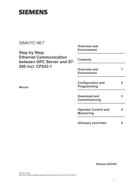
<strong>SIMATIC</strong> <strong>NET</strong><br />
<strong>Step</strong> <strong>by</strong> <strong>Step</strong>:<br />
<strong>Ethernet</strong> <strong>Communication</strong><br />
<strong>between</strong> <strong>OPC</strong> Server and S7-<br />
200 incl. CP243-1<br />
Manual<br />
<strong>Step</strong> <strong>by</strong> <strong>Step</strong>:<br />
<strong>Ethernet</strong> <strong>Communication</strong> <strong>between</strong> <strong>OPC</strong> Server and S7-200 incl. CP243-1<br />
Overview and<br />
Environment<br />
Contents<br />
Overview and<br />
Environment<br />
Configuration and<br />
Programming<br />
Download and<br />
Commissioning<br />
Operator Control and<br />
Monitoring<br />
Glossary and Index 5<br />
Release 02/2003<br />
1<br />
1<br />
2<br />
3<br />
4
Classification of Safety-Related Notices<br />
!<br />
!<br />
!<br />
This document contains notices which you should observe to ensure your own<br />
personal safety, as well as to protect the product and connected equipment. These<br />
notices are highlighted in the manual <strong>by</strong> a warning triangle and are marked as follows<br />
according to the level of danger:<br />
Danger<br />
indicates that death or severe personal injury will result if proper precautions are not<br />
taken.<br />
Warning<br />
indicates that death or severe personal injury can result if proper precautions are not<br />
taken.<br />
Caution<br />
with warning triangle indicates that minor personal injury can result if proper<br />
precautions are not taken.<br />
Caution<br />
without warning triangle indicates that damage to property can result if proper<br />
precautions are not taken.<br />
Notice<br />
indicates that an undesirable result or status can result if the relevant notice is<br />
ignored.<br />
Note<br />
highlights important information on the product, using the product, or part of the<br />
documentation that is of particular importance and that will be of benefit to the user.<br />
Copyright Siemens AG, 1998 to 2003, All rights reserved<br />
The reproduction, transmission or use of this document or its contents is<br />
not permitted without express written authority. Offenders will be liable for<br />
damages. All rights, including rights created <strong>by</strong> patent grant or registration<br />
of a utility or design, are reserved.<br />
Siemens AG<br />
Bereich Automatisierungs- und Antriebstechnik<br />
Geschäftsgebiet Industrie-Automatisierungssysteme<br />
Postfach 48 48, D-90327 Nürnberg<br />
Disclaimer<br />
We have checked the contents of this manual for agreement with the<br />
hardware described. Since deviations cannot be precluded entirely, we<br />
cannot guarantee full agreement. However, the data in this manual are<br />
reviewed regularly and any necessary corrections included in subsequent<br />
editions. Suggestions for improvement are welcomed.<br />
© Siemens AG 1998 to 2003<br />
Technical data subject to change.<br />
Siemens Aktiengesellschaft Printed in the Federal Republic of Germany 2
Trademarks<br />
<strong>SIMATIC</strong>®, <strong>SIMATIC</strong> <strong>NET</strong>®, SINEC® and <strong>SIMATIC</strong> <strong>NET</strong> Networking for Industry ®<br />
are registered trademarks of Siemens AG.<br />
Third parties using for their own purposes any other names in this document which<br />
refer to trademarks might infringe upon the rights of the trademark owners.<br />
Safety Instructions Regarding your Product<br />
Qualified Personnel<br />
Before you use the product described here, read the safety instructions below<br />
thoroughly.<br />
Only qualified personnel should be allowed to install and work on this equipment.<br />
Qualified persons are defined as persons who are authorized to commission, to<br />
ground, and to tag circuits, equipment, and systems in accordance with established<br />
safety practices and standards.<br />
Correct Usage of Hardware Products<br />
Please note the following instructions regarding the correct usage of hardware<br />
products:<br />
Caution<br />
This device and its components may only be used for the applications described in the<br />
catalog or the technical description, and only in connection with devices or<br />
components from other manufacturers which have been approved or recommended<br />
<strong>by</strong> Siemens.<br />
This product can only function correctly and safely if it is transported, stored, set up,<br />
and installed correctly, and operated and maintained as recommended.<br />
Before you use the supplied sample programs or programs you have written yourself,<br />
make certain that no injury to persons nor damage to equipment can result in your<br />
plant or process.<br />
EU Directive: Do not start up until you have established that the machine on which<br />
you intend to run this component complies with the directive 89/392/EEC<br />
<strong>Step</strong> <strong>by</strong> <strong>Step</strong>:<br />
<strong>Ethernet</strong> <strong>Communication</strong> <strong>between</strong> <strong>OPC</strong> Server and S7-200 incl. CP243-1<br />
3
Correct Usage of Software Products<br />
Prior to Startup<br />
Please note the following instructions regarding the correct usage of software<br />
products:<br />
Caution<br />
This software may only be used for the applications described in the catalog or the<br />
technical description, and only in connection with software products, devices, or<br />
components from other manufacturers which have been approved or recommended<br />
<strong>by</strong> Siemens.<br />
Before you use the supplied sample programs or programs you have written yourself,<br />
make certain that no injury to persons nor damage to equipment can result in your<br />
plant or process.<br />
Prior to startup, please note the following warning:<br />
Caution<br />
Prior to startup you must observe the notes in the relevant documentation. For<br />
ordering data of the documentation please refer to catalogs or contact your local<br />
SIEMENS representative.<br />
<strong>Step</strong> <strong>by</strong> <strong>Step</strong>:<br />
<strong>Ethernet</strong> <strong>Communication</strong> <strong>between</strong> <strong>OPC</strong> Server and S7-200 incl. CP243-1<br />
4
Preface<br />
Purpose of the Manual<br />
Aims<br />
The Package<br />
<strong>Step</strong> <strong>by</strong> <strong>Step</strong>:<br />
<strong>Ethernet</strong> <strong>Communication</strong> <strong>between</strong> <strong>OPC</strong> Server and S7-200 incl. CP243-1<br />
Preface<br />
This manual supports you when creating user programs and configurations in the<br />
<strong>OPC</strong> environment. The activities involved in creating a program and the required<br />
configuration work are presented in the form of a sequential series of steps. The<br />
configurations used are created with the basic software <strong>SIMATIC</strong> STEP 7 or NCM<br />
PC.<br />
This manual serves as a reference work for configuration and communication with<br />
<strong>OPC</strong> components.<br />
This manual should help you to expand the components described and to integrate<br />
them in your program.<br />
We assume that you are thoroughly familiar with your programs and development<br />
environment.<br />
This sample project consists of the following parts:<br />
● Documentation commissioning, documentation Excel<br />
● Microsoft Excel file incl. VBA implementation as example<br />
● MicroWIN project file for download<br />
● SimaticNet <strong>OPC</strong> project file for observing variables<br />
Validity of this Manual<br />
This manual applies the following software versions:<br />
5
● <strong>SIMATIC</strong> MicroWin V3.2 + SP1 or higher<br />
● <strong>SIMATIC</strong> <strong>NET</strong> S7 <strong>OPC</strong> Server is part of the SOFT<strong>NET</strong> S7/Windows 6.0<br />
package of Industrial <strong>Ethernet</strong><br />
Baugruppen MLFB<br />
SimaticNet S7-<strong>OPC</strong> Server 6GK1704-1CW60-3AA0<br />
Simatic S7-224 (DC-Version)<br />
Simatic S7-224 (Relais-Version)<br />
<strong>Step</strong> <strong>by</strong> <strong>Step</strong>:<br />
<strong>Ethernet</strong> <strong>Communication</strong> <strong>between</strong> <strong>OPC</strong> Server and S7-200 incl. CP243-1<br />
6ES7 214-1AD22-0XB0<br />
6ES7 214-1BD22-0XB0<br />
Simatic CP243-1 6GK7 243-1EX00-0XE0<br />
Required Documentation<br />
Preface<br />
The following documentation contains additional information on the MicroWIN basic<br />
software of the <strong>SIMATIC</strong> S7-200 programmable controller and can be obtained<br />
from your local Siemens office.<br />
Topic Document Order Number<br />
S7-200 Dokumentation Automation System S7-200<br />
• System Manual<br />
Basic information on the <strong>OPC</strong><br />
interface and installation and<br />
commissioning of the<br />
<strong>SIMATIC</strong> <strong>NET</strong> <strong>OPC</strong> Server.<br />
Industrial <strong>Communication</strong><br />
with <strong>SIMATIC</strong> <strong>NET</strong><br />
• User Manual<br />
Orientation in the General Documentation Landscape<br />
6ES7 298-8FA22-8BH0<br />
6GK1 971-1GA00-0AA1<br />
To set up the S7 controller and to prepare for operation, you require the following<br />
documentation:<br />
● Automation System S7-200, System Manual<br />
Structure of the Documentation<br />
The <strong>SIMATIC</strong> <strong>NET</strong> Documentation includes the following:<br />
● Manual<br />
● Product information<br />
● Installation instructions<br />
● Readme.txt files on the data medium of the software product<br />
6
Finding Your Way Through the Manual<br />
<strong>Step</strong> <strong>by</strong> <strong>Step</strong>:<br />
<strong>Ethernet</strong> <strong>Communication</strong> <strong>between</strong> <strong>OPC</strong> Server and S7-200 incl. CP243-1<br />
Preface<br />
To help you to locate specific information quickly, the manual includes the following<br />
tools:<br />
● At the start of the manual, you will find a full table of contents and a list of<br />
figures and tables contained in the manual.<br />
● In the chapters, you will see a brief overview of the contents of the sections in<br />
the left margin.<br />
● After the appendix, there is a glossary that defines the most important technical<br />
terms used in the manual.<br />
● At the back of the manual, there is a detailed index that allows you to locate<br />
information quickly.<br />
Documentation on Programming<br />
CD-ROM<br />
The appendix includes a list of the documentation you require to program and<br />
commission the S7 controller. You will also find a list of technical books on the<br />
topic of programmable controllers.<br />
You can also order the entire <strong>SIMATIC</strong> S7 documentation as a collection on CD-<br />
ROM.<br />
Personnel Qualification Requirements<br />
Only qualified personnel should be allowed to install and work on this equipment.<br />
Qualified personnel as referred to in the operating instructions or in the warning<br />
notes are defined as persons who are familiar with the installation, assembly,<br />
startup and operation of this product and who possess the relevant qualifications<br />
for their work, for example:<br />
● Training in or authorization for connecting up, grounding or labeling circuits and<br />
devices or systems in accordance with current standards in safety technology;<br />
● Training in or authorization for the maintenance and use of suitable safety<br />
equipment in accordance with current standards in safety technology;<br />
● First aid qualification.<br />
7
Further Support<br />
WhotoContact<br />
License<br />
Certification<br />
<strong>Step</strong> <strong>by</strong> <strong>Step</strong>:<br />
<strong>Ethernet</strong> <strong>Communication</strong> <strong>between</strong> <strong>OPC</strong> Server and S7-200 incl. CP243-1<br />
Preface<br />
If you have further questions on <strong>SIMATIC</strong> products, please contact your local<br />
Siemens office or representative. You will find the addresses in the catalogs, on the<br />
Internet and in CompuServe (go autforum).<br />
If you have technical questions about using the software and your problem is not<br />
dealt with in the documentation or in the integrated help system, please contact<br />
your Siemens representative or dealer.<br />
You will find the addresses:<br />
● In the "Readme.rtf" file in the main folder of the <strong>SIMATIC</strong> <strong>NET</strong> CD<br />
● Internet http://www.siemens.de/simatic-net<br />
● In Catalog IK PI<br />
Note that you can only use the samples described on this CD if you have valid<br />
licenses for the software required.<br />
Note<br />
You can obtain demonstration versions of the required software products for test or<br />
demonstration purposes and to familiarize yourself with the functions.<br />
The products and systems listed in this document are manufactured and marketed<br />
using a quality management system complying with DIN ISO 9001 and certified <strong>by</strong><br />
DQS (certificate registration no. 2613). The DQS certificate is recognized in all<br />
IQNet countries (Reg. No.: 2613).<br />
Standards and Approvals<br />
The S7 controllers meet the requirements and criteria of IEC 1131, Part 2. The S7<br />
controllers meet the requirements for the CE Mark. CSA, UL and FM approvals<br />
have been obtained for the S7 controllers.<br />
You will find more detailed information on the approvals and standards in the<br />
appendix ....<br />
8
Contents<br />
<strong>Step</strong> <strong>by</strong> <strong>Step</strong>:<br />
<strong>Ethernet</strong> <strong>Communication</strong> <strong>between</strong> <strong>OPC</strong> Server and S7-200 incl. CP243-1<br />
Contents<br />
1 Overview and Environment ...................................................... 10<br />
1.1 Schematic of the Environment .................................................... 11<br />
1.2 General Description .................................................................... 12<br />
1.3 Function Diagram........................................................................ 14<br />
1.4 Required Software ...................................................................... 15<br />
1.5 Required Hardware ..................................................................... 16<br />
1.6 Suitability for a Different Hardware Configuration ....................... 17<br />
2 Configuration and Programming ............................................. 18<br />
2.1 PC Station................................................................................... 19<br />
2.2 PLC Station................................................................................. 29<br />
2.2.1 Parameters of Subroutine (ETH0_CTRL) ....................................................... 34<br />
2.2.2 Cyclic Program (Main).................................................................................... 35<br />
3 Download and Commissioning................................................ 36<br />
3.1 Overview ..................................................................................... 37<br />
3.2 PC Station................................................................................... 38<br />
3.3 PLC Station................................................................................. 39<br />
4 Operator Control and Monitoring ............................................ 40<br />
4.1 Overview ..................................................................................... 41<br />
4.2 <strong>OPC</strong> Client (<strong>OPC</strong> Scout)............................................................. 42<br />
4.3 MicroWin (Chart Status).............................................................. 44<br />
5 Glossary and Index ................................................................... 45<br />
9
Overview and Environment<br />
In this chapter the sample plant and the functional principles of the environment<br />
are described. Additional the required hard- and software will be listed.<br />
<strong>Step</strong> <strong>by</strong> <strong>Step</strong>:<br />
<strong>Ethernet</strong> <strong>Communication</strong> <strong>between</strong> <strong>OPC</strong> Server and S7-200 incl. CP243-1<br />
1<br />
10
1.1 Schematic of the Environment<br />
Block Diagram<br />
<strong>Step</strong> <strong>by</strong> <strong>Step</strong>:<br />
<strong>Ethernet</strong> <strong>Communication</strong> <strong>between</strong> <strong>OPC</strong> Server and S7-200 incl. CP243-1<br />
Overview and Environment<br />
The following figure shows the components of the sample plant in principle:<br />
Figure 1-1 Block Diagram<br />
Environment<br />
PLC-Station<br />
CPU<br />
S7-200<br />
<strong>Ethernet</strong>-CP<br />
CP 243-1<br />
PC-Station<br />
Industrial <strong>Ethernet</strong><br />
SimaticNet<br />
<strong>OPC</strong> Scout<br />
SimaticNet<br />
<strong>OPC</strong> Server<br />
<strong>Ethernet</strong>-NIC<br />
(e.g..CP1613)<br />
The controller consists of S7-200 PLC including the <strong>Ethernet</strong> communication<br />
processor (CP243-1). Via <strong>Ethernet</strong> (TP: Twisted-Pair) the controller is connected to<br />
the PC (Personal Computer). Inside the PC an <strong>Ethernet</strong> adapter (e.g. 3Com,<br />
CP1613 or others) is connected through its driver to SimaticNet <strong>OPC</strong> Server, which<br />
provides the data. The <strong>OPC</strong> Scout, an <strong>OPC</strong> Client that is shipped with SimaticNet,<br />
displays the data from the <strong>OPC</strong> Server.<br />
Note<br />
Using a direct connection <strong>between</strong> two <strong>Ethernet</strong> communication devices, a socalled<br />
Cross Cable is required.<br />
11
Overview and Environment<br />
1.2 General Description<br />
PLC Station<br />
PC Station<br />
When using the CP243-1 in an S7-200 environment the S7-Protocoll over <strong>Ethernet</strong><br />
is supported. The S7-Protocoll includes different services for communication. The<br />
so-called Variable services (Put/Get) are used in this example. Here the S7-200<br />
acts as the passive communication partner, meaning the S7-200 awaits the<br />
connection request and responds on Put-Requests (write data into the PLC) or<br />
responds on Get-Request (read data from the PLC). The S7-200 is passive and<br />
reacts on active requests, thus the functionality is called a server. Inside the S7-<br />
200 a passive S7-connection must be configured.<br />
The PC supports the S7-Protocoll over <strong>Ethernet</strong>. Here the protocol is executed on<br />
the network interface controller (e.g. CP1613) and the S7-<strong>OPC</strong>Server provides the<br />
data from the PLC. The <strong>OPC</strong> Client (<strong>OPC</strong> Scout) starts the <strong>OPC</strong> Server and the<br />
server runs the S7-Protocoll services (Put/Get) on the NIC. The active call of<br />
services is described as client functionality.<br />
<strong>Communication</strong> Relations<br />
The S7 <strong>OPC</strong> Server provides, with respect to the <strong>OPC</strong> Client, a server interface<br />
compliant to the dedicated <strong>OPC</strong> Standard. With respect to the PLC the <strong>OPC</strong><br />
Server acts as S7 Client and the PLC serves data as S7 Server.<br />
Figure 1-2 Client – Server Relations<br />
<strong>OPC</strong> Client<br />
(<strong>OPC</strong> Scout)<br />
<strong>OPC</strong> Server<br />
(SimaticNet)<br />
S7 Client<br />
(Sapi S7, aktive)<br />
<strong>OPC</strong> function<br />
(e.g. SyncWrite)<br />
S7 function<br />
(e.g. Put)<br />
S7 Server<br />
(S7-200, passive)<br />
<strong>Step</strong> <strong>by</strong> <strong>Step</strong>:<br />
<strong>Ethernet</strong> <strong>Communication</strong> <strong>between</strong> <strong>OPC</strong> Server and S7-200 incl. CP243-1<br />
PC Station<br />
PLC Station<br />
12
Overview and Environment<br />
Connection Type<br />
For communication <strong>between</strong> PC and controller this example uses the S7 Protocol<br />
(Put/Get services) on TCP/IP. Between the two devices a S7 Connection must be<br />
established. When communicating to <strong>OPC</strong> Server, S7-200 are always passive,<br />
thus the PC-Station actively establishes the connection. The S7 Connection is<br />
configured using NetPro (Network Projection Tool as part of NCM software<br />
package).<br />
Note<br />
Booth communication partners need information about the connection. The single<br />
sided specified S7 Connection must be loaded into the PC-Station. The<br />
configuration will not be loaded into the PLC using NetPro. However, the<br />
connection (also single sided specified) must be configured and loaded into the<br />
S7-200.<br />
<strong>Step</strong> <strong>by</strong> <strong>Step</strong>:<br />
<strong>Ethernet</strong> <strong>Communication</strong> <strong>between</strong> <strong>OPC</strong> Server and S7-200 incl. CP243-1<br />
13
Overview and Environment<br />
1.3 Function Diagram<br />
The following diagram shows the principle function of this example regarding a<br />
writing call to the PLC.<br />
<strong>OPC</strong> Client <strong>OPC</strong> Server CP-243-1<br />
Prepare Write<br />
Request<br />
Evaluate Result<br />
>> Continue<br />
Call SyncWrite<br />
Return SyncWrite<br />
Figure 1-3 Function Diagram<br />
Pass to S7<br />
Protocoll<br />
Update Cache<br />
Pass to <strong>OPC</strong><br />
Call Put<br />
Return Put<br />
<strong>Step</strong> <strong>by</strong> <strong>Step</strong>:<br />
<strong>Ethernet</strong> <strong>Communication</strong> <strong>between</strong> <strong>OPC</strong> Server and S7-200 incl. CP243-1<br />
Data Buffer<br />
pass to PLC<br />
backplane<br />
finish<br />
S7-200-Station<br />
Cyclic<br />
Call ETHO<br />
14
Overview and Environment<br />
1.4 Required Software<br />
Operating System<br />
<strong>SIMATIC</strong><br />
To run this example the following software packages are required.<br />
● Microsoft Windows 2000 Professional SP3 or Windows XP Professional SP1<br />
● SimaticNet CD 7/02, PC-Software V6.0 for Windows 2000 or SimaticNet CD<br />
7/02, PC-Software V6.1 for Windows XP<br />
This software package includes drivers for the communication processor CP1613<br />
and other <strong>Ethernet</strong> cards (NIC), das S7 Protocol and the S7 <strong>OPC</strong> Server including<br />
the <strong>OPC</strong> Scout.<br />
● <strong>SIMATIC</strong> NCM S7 IE V5.2 or <strong>SIMATIC</strong> STEP 7 V5.2<br />
This software package includes configuration software HWKonfig and NetPro with<br />
the required Hardware Catalog.<br />
● <strong>SIMATIC</strong> STEP 7 MicroWin V3.2 SP1<br />
This software package includes programming- and configuration tool for S7-200<br />
controllers.<br />
<strong>Step</strong> <strong>by</strong> <strong>Step</strong>:<br />
<strong>Ethernet</strong> <strong>Communication</strong> <strong>between</strong> <strong>OPC</strong> Server and S7-200 incl. CP243-1<br />
15
Overview and Environment<br />
1.5 Required Hardware<br />
PC Station<br />
PLC Station<br />
Miscellaneous<br />
IBM PC including <strong>Ethernet</strong> Card (e.g. <strong>Communication</strong> Processor CP1613)<br />
<strong>SIMATIC</strong> S7-224 Controller including <strong>Ethernet</strong> <strong>Communication</strong> Processor CP243-1<br />
<strong>Ethernet</strong> Hub and 2x <strong>Ethernet</strong> Cable with RJ45 connector, so-called patch cable or<br />
1x Cross Cable for direct connection devices.<br />
<strong>Step</strong> <strong>by</strong> <strong>Step</strong>:<br />
<strong>Ethernet</strong> <strong>Communication</strong> <strong>between</strong> <strong>OPC</strong> Server and S7-200 incl. CP243-1<br />
16
Overview and Environment<br />
1.6 Suitability for a Different Hardware Configuration<br />
Important<br />
The samples relate to specific hardware configurations. These must exist to ensure<br />
problem-free operation.<br />
If you want to use a different configuration, adaptations will be necessary. (See<br />
also the notes below)<br />
Note<br />
Using a different CPU (e.g.: CPU 222)<br />
If you want to use a different CPU, you only need to run the <strong>Ethernet</strong>-Assistant as<br />
part of <strong>Step</strong>7-MicroWin again and the Module-Command-Byte must be changed.<br />
Using a different <strong>Ethernet</strong> card in the PC<br />
If you want to use a different PCI adapter from the CP1613, you only need to<br />
replace the adapter in the hardware configuration (HWKonfig). When using third<br />
party NIC the CP „IE General“ must be selected.<br />
<strong>Step</strong> <strong>by</strong> <strong>Step</strong>:<br />
<strong>Ethernet</strong> <strong>Communication</strong> <strong>between</strong> <strong>OPC</strong> Server and S7-200 incl. CP243-1<br />
17
Configuration and Programming<br />
In this chapter the configuration of the PC Station and the programming of the<br />
Controller is shown in form of a <strong>Step</strong>-<strong>by</strong>-<strong>Step</strong> description.<br />
<strong>Step</strong> <strong>by</strong> <strong>Step</strong>:<br />
<strong>Ethernet</strong> <strong>Communication</strong> <strong>between</strong> <strong>OPC</strong> Server and S7-200 incl. CP243-1<br />
2<br />
18
2.1 PC Station<br />
General<br />
<strong>Step</strong>-<strong>by</strong>-<strong>Step</strong><br />
<strong>Step</strong> <strong>by</strong> <strong>Step</strong>:<br />
<strong>Ethernet</strong> <strong>Communication</strong> <strong>between</strong> <strong>OPC</strong> Server and S7-200 incl. CP243-1<br />
Configuration and Programming<br />
After placing the <strong>Ethernet</strong> adapter (e.g. CP1613) in the PC Station, the SimaticNet<br />
PC Software V6.x must be installed. Installing the card, the SimaticNet Software<br />
including the required license is described in a different document. Refer to the<br />
notes in the product manual and related product information including the read me<br />
files.<br />
Note<br />
Regarding this documentation fault free placement and fault free installation of<br />
SimaticNet PC Software and NCM PC Software is assumed.<br />
The following steps describe the configuration and set up of connections. Important<br />
dialogs are illustrated.<br />
19
Figure 2-1 <strong>Step</strong> 1<br />
<strong>Step</strong> Description<br />
<strong>Step</strong> <strong>by</strong> <strong>Step</strong>:<br />
<strong>Ethernet</strong> <strong>Communication</strong> <strong>between</strong> <strong>OPC</strong> Server and S7-200 incl. CP243-1<br />
Configuration and Programming<br />
1 The <strong>Ethernet</strong> adapter must be switched into „Configured mode“ to be<br />
used with the <strong>OPC</strong> Server. Using Start ���� Simatic ���� SimaticNet ����<br />
Settings ���� Configuration Console the <strong>Ethernet</strong> <strong>Communication</strong><br />
Processor is selected and inside „Modules“ under „General“ the<br />
operating mode is switched to „Configured mode“.<br />
20
Figure 2-2 <strong>Step</strong> 3<br />
<strong>Step</strong> Description<br />
<strong>Step</strong> <strong>by</strong> <strong>Step</strong>:<br />
<strong>Ethernet</strong> <strong>Communication</strong> <strong>between</strong> <strong>OPC</strong> Server and S7-200 incl. CP243-1<br />
Configuration and Programming<br />
2 For the local PC-Station a connection must be configured. Using Start<br />
���� Simatic ���� SimaticNet ���� Settings ���� Commissioning Wizard the<br />
wizard for configuring the local PC Station is started.<br />
3 In the second dialog of the wizard the “PC Station Wizard” is started <strong>by</strong><br />
pressing the button.<br />
21
Figure 2-3 <strong>Step</strong> 4<br />
<strong>Step</strong> Description<br />
<strong>Step</strong> <strong>by</strong> <strong>Step</strong>:<br />
<strong>Ethernet</strong> <strong>Communication</strong> <strong>between</strong> <strong>OPC</strong> Server and S7-200 incl. CP243-1<br />
Configuration and Programming<br />
4 The option „Change local settings“ is selected and must be<br />
acknowledged <strong>by</strong> pressing the “Next >” button. In the following dialog<br />
the option “Edit network and connection configuration” must be<br />
selected confirmed with the “Finish” button.<br />
22
Figure 2-4 <strong>Step</strong> 5<br />
<strong>Step</strong> Description<br />
<strong>Step</strong> <strong>by</strong> <strong>Step</strong>:<br />
<strong>Ethernet</strong> <strong>Communication</strong> <strong>between</strong> <strong>OPC</strong> Server and S7-200 incl. CP243-1<br />
Configuration and Programming<br />
5 The local PC Station is opened in the network and connection<br />
configuration tool NetPro. A connection of type “S7-connection” must<br />
be created. Therefore a double click in the connection list of the <strong>OPC</strong><br />
Server application is required.<br />
23
Figure 2-5 <strong>Step</strong> 6<br />
<strong>Step</strong> Description<br />
<strong>Step</strong> <strong>by</strong> <strong>Step</strong>:<br />
<strong>Ethernet</strong> <strong>Communication</strong> <strong>between</strong> <strong>OPC</strong> Server and S7-200 incl. CP243-1<br />
Configuration and Programming<br />
6 When inserting the new connection the connection partner is marked<br />
as “unspecified”, because the S7-200 Station (S7 server) is not part of<br />
the local project (locprj), that is representing the PC Station..<br />
24
Figure 2-6 <strong>Step</strong> 7<br />
<strong>Step</strong> Description<br />
<strong>Step</strong> <strong>by</strong> <strong>Step</strong>:<br />
<strong>Ethernet</strong> <strong>Communication</strong> <strong>between</strong> <strong>OPC</strong> Server and S7-200 incl. CP243-1<br />
Configuration and Programming<br />
7 The properties dialog of the S7 connection needs the IP-Address of the<br />
partner device (here CP 243-1).<br />
Note<br />
The IP-Addresses shown in the Figure are examples and can be different.<br />
25
Figure 2-7 <strong>Step</strong> 8<br />
<strong>Step</strong> Description<br />
<strong>Step</strong> <strong>by</strong> <strong>Step</strong>:<br />
<strong>Ethernet</strong> <strong>Communication</strong> <strong>between</strong> <strong>OPC</strong> Server and S7-200 incl. CP243-1<br />
Configuration and Programming<br />
8 By pressing the button „Address Details...“ the dialog for setting the<br />
connection resources is shown up. The resources of the PC Station are<br />
pre selected <strong>by</strong> NetPro, but for the unspecified partner (S7 200) the<br />
resource must be typed in (here 10.00).<br />
26
Figure 2-8 <strong>Step</strong> 9<br />
<strong>Step</strong> Description<br />
<strong>Step</strong> <strong>by</strong> <strong>Step</strong>:<br />
<strong>Ethernet</strong> <strong>Communication</strong> <strong>between</strong> <strong>OPC</strong> Server and S7-200 incl. CP243-1<br />
Configuration and Programming<br />
9 After closing all properties dialogs the new configuration must be<br />
complied using “Save and Compile”. Than the S7 connection must be<br />
loaded into the PC Station using PLC ���� Download ���� Selected<br />
Stations<br />
Note<br />
After downloading the PC Station a yellow exclamation mark flashes in the down<br />
right in the taskbar. This indicates a new diagnostic message in the Station<br />
Configuration Editor stating a successful restart of the <strong>OPC</strong> Server and <strong>Ethernet</strong><br />
adapter as well as the station manager. Opening the Configuration Editor is<br />
interpreted as confirmation and the yellow exclamation mark disappears.<br />
Note<br />
In the case of a faulty download the diagnostic messages of the Station<br />
Configuration Editor will reference the cause of failure (e.g. wrong subnet mask).<br />
27
Figure 2-9 <strong>Step</strong> 10<br />
<strong>Step</strong> Description<br />
<strong>Step</strong> <strong>by</strong> <strong>Step</strong>:<br />
<strong>Ethernet</strong> <strong>Communication</strong> <strong>between</strong> <strong>OPC</strong> Server and S7-200 incl. CP243-1<br />
Configuration and Programming<br />
10 After confirmation of all following steps of the Commissioning Wizard<br />
using the buttons “Next >” and “Finish” the Configuration Console<br />
opens up automatically. Here the selection of protocols should be set to<br />
the actually used ones only.<br />
Note<br />
Depending on the selection of protocols the address space of the <strong>OPC</strong> Server can<br />
look different.<br />
28
2.2 PLC Station<br />
General<br />
<strong>Step</strong> <strong>by</strong> <strong>Step</strong><br />
<strong>Step</strong> <strong>by</strong> <strong>Step</strong>:<br />
<strong>Ethernet</strong> <strong>Communication</strong> <strong>between</strong> <strong>OPC</strong> Server and S7-200 incl. CP243-1<br />
Configuration and Programming<br />
After installing the <strong>Communication</strong> Processor CP243-1 in the PLC Station, a<br />
passive S7 connection must be configured. When communication to the <strong>OPC</strong><br />
Server the S7-200 must always be configured as S7 Server, additionally the S7-<br />
200 will always be the passive communication partner.<br />
The installation of the <strong>Communication</strong> Processor, the wiring and commissioning is<br />
described in an additional document. Refer to the stated notes and the related<br />
product information.<br />
Note<br />
Regarding this documentation a fault free installation, wiring and commissioning of<br />
the <strong>Communication</strong> Processor CP 243-1 is assumed.<br />
The following steps describe the configuration of connections and programming of<br />
the CPU. Important dialogs are illustrated.<br />
29
Figure 2-10 <strong>Step</strong> 3<br />
<strong>Step</strong> Description<br />
<strong>Step</strong> <strong>by</strong> <strong>Step</strong>:<br />
<strong>Ethernet</strong> <strong>Communication</strong> <strong>between</strong> <strong>OPC</strong> Server and S7-200 incl. CP243-1<br />
Configuration and Programming<br />
1 From <strong>Step</strong>7-Microwin “<strong>Ethernet</strong> Wizard is started. This can be done<br />
using the menu bar Tools ���� <strong>Ethernet</strong> Wizard or directly using the<br />
Navigation Bar (left side).<br />
2 The module position is set in the second dialog of the Wizard. The<br />
default position “0” is located directly next to the CPU, all other<br />
positions increase from there on.<br />
3 The IP Address and the Subnet mask is set in the third dialog of the<br />
Wizard.<br />
Note<br />
The IP-Addresses shown in the Figure are examples and can be different.<br />
Note<br />
The BOOTP Server for dynamically assigning the IP-Address should not be<br />
selected because configuration of the <strong>OPC</strong> Server’s connection (PC Station)<br />
expects a fixed IP Address.<br />
30
Figure 2-11 <strong>Step</strong> 4<br />
<strong>Step</strong> Description<br />
<strong>Step</strong> <strong>by</strong> <strong>Step</strong>:<br />
<strong>Ethernet</strong> <strong>Communication</strong> <strong>between</strong> <strong>OPC</strong> Server and S7-200 incl. CP243-1<br />
Configuration and Programming<br />
4 To calculate the Command Byte all output <strong>by</strong>tes (QB), that are located<br />
before the CP243-1, must be added. The next following (not taken)<br />
<strong>by</strong>te will be the Command Byte. E.g. the onboard output <strong>by</strong>tes of CPU<br />
224 use QB0 and QB1, the next unused Command Byte will be QB2.<br />
Additionally the number of connections is set, to be configured during<br />
the following dialogs.<br />
31
Figure 2-12 <strong>Step</strong> 5<br />
<strong>Step</strong> Description<br />
<strong>Step</strong> <strong>by</strong> <strong>Step</strong>:<br />
<strong>Ethernet</strong> <strong>Communication</strong> <strong>between</strong> <strong>OPC</strong> Server and S7-200 incl. CP243-1<br />
Configuration and Programming<br />
5 The required properties are set for the requested connection. The S7-<br />
200 runs as server and responds to connection requests of the <strong>OPC</strong><br />
Server (PC Station). Additionally the local properties of the connection<br />
(CP243-1) are set to the IP-Address from which connect requests will<br />
be accepted (here the IP of the PC Station must be typed in). Within<br />
the remote properties of the communication partner the TSAP is<br />
defined (here “10.11” compare NetPro S7 connection Properties ����<br />
Address Details)<br />
Note<br />
The settings of the IP-Address and TSAP must be identically to the settings made<br />
during the connection configuration in NetPro (PC Station).<br />
32
Figure 2-13 <strong>Step</strong> 7<br />
<strong>Step</strong> Description<br />
<strong>Step</strong> <strong>by</strong> <strong>Step</strong>:<br />
<strong>Ethernet</strong> <strong>Communication</strong> <strong>between</strong> <strong>OPC</strong> Server and S7-200 incl. CP243-1<br />
Configuration and Programming<br />
6 After finishing the connection configuration the required memory must<br />
be reserved to avoid overwriting of configuration data.<br />
7 The configuration data is stored within the V-memory. Memory area of<br />
correct size must be provided. The Wizard can suggest unused<br />
memory.<br />
<strong>Step</strong> Description<br />
8 During the next step a subroutine (ETH0_CTRL) is generated and will<br />
be available in the engineering environment.<br />
9 The subroutine (ETH0_CTRL) must be called once during each cycle<br />
(Main). The routine initializes the CP243-1 and provides the error<br />
codes.<br />
33
2.2.1 Parameters of Subroutine (ETH0_CTRL)<br />
Figure 2-14 Subroutine<br />
Input parameter EN<br />
<strong>Step</strong> <strong>by</strong> <strong>Step</strong>:<br />
<strong>Ethernet</strong> <strong>Communication</strong> <strong>between</strong> <strong>OPC</strong> Server and S7-200 incl. CP243-1<br />
Configuration and Programming<br />
Permanently set to “1” (SM0.0), to excetute the subroutine in every cycle.<br />
Output parameter CP_Ready<br />
1 = CP is ready to operate, 0 = CP not ready to operate.<br />
Output parameter Ch_Ready<br />
Data type Word, each individual bit of the lower <strong>by</strong>te is dedicated to a certain<br />
channel (connection). E.g.bit x.0 � connection 0. The value of each bit indicates<br />
that the connection is established and ready for this channel or not. High <strong>by</strong>te is<br />
not used yet.<br />
Output parameter Fehler<br />
Data type Word, provides an error code regarding the cause of the fault.<br />
34
2.2.2 Cyclic Program (Main)<br />
ExtractofAWLCode<br />
<strong>Step</strong> <strong>by</strong> <strong>Step</strong>:<br />
<strong>Ethernet</strong> <strong>Communication</strong> <strong>between</strong> <strong>OPC</strong> Server and S7-200 incl. CP243-1<br />
Configuration and Programming<br />
The following extract of code shows the principle operation of the subroutine to<br />
demonstrate the cyclic function call with the required parameter set.<br />
Network 1 //CP initialize<br />
LD Immer_ein<br />
CALL ETH0_CTRL, CP_Ready, Channel_Ready, Error_CTRL<br />
35
Download and Commissioning<br />
This chapter describes the download of the configuration and program of all<br />
required components and the steps for commissioning.<br />
<strong>Step</strong> <strong>by</strong> <strong>Step</strong>:<br />
<strong>Ethernet</strong> <strong>Communication</strong> <strong>between</strong> <strong>OPC</strong> Server and S7-200 incl. CP243-1<br />
3<br />
36
Download and Commissioning<br />
3.1 Overview<br />
General<br />
Block Diagram<br />
The so-called download describes the process to provide configuration information<br />
for the dedicated device. Using an engineering tool (Setp7, HWKonfig, NetPro) a<br />
configuration is created. The configuration data includes information about the IP-<br />
Address as well as connection information. In addition system blocks including e.g.<br />
TSAPs are generated. This system configuration data is transmitted to the device<br />
during the “download” of the station.<br />
The following figure shows the devices and their configuration tools as used in this<br />
example.<br />
CPU 224<br />
Figure 3-1 Download<br />
<strong>Step</strong> 7- MicroWin<br />
<strong>Ethernet</strong> Wizard<br />
S7-connection<br />
<strong>Step</strong> <strong>by</strong> <strong>Step</strong>:<br />
<strong>Ethernet</strong> <strong>Communication</strong> <strong>between</strong> <strong>OPC</strong> Server and S7-200 incl. CP243-1<br />
<strong>Step</strong> 7<br />
HWKonfig / NetPro<br />
load load<br />
incl.<br />
information on:<br />
<strong>OPC</strong><br />
Server<br />
CP 243-1<br />
192.168.147.120 192.168.147.100<br />
<strong>Ethernet</strong><br />
adapter<br />
TSAP 10.00<br />
TSAP 11.10<br />
37
Download and Commissioning<br />
3.2 PC Station<br />
General<br />
Local Project<br />
The PC Station consists of <strong>Ethernet</strong> adapter and <strong>OPC</strong> Server. After installing the<br />
SimaticNet PC Software the configuration tools HWKonfig (Hardware<br />
Configuration) and NetPro (Network Configuration) are available. The<br />
Commissioning Wizard guides through the different steps and launches the<br />
configuration tool.<br />
For the PC Station automatically a local project (<strong>Step</strong>7 project) is generated that<br />
consists of PC Station representing the local computer. This <strong>Step</strong>7 project (locprj)<br />
includes exactly one rack of type “Simatic PC Station” and this rack resides exactly<br />
one application of type “<strong>OPC</strong> Server” (usually in slot 1). If the <strong>Ethernet</strong> adapter was<br />
set to “configured mode”, the rack hosts a communication processor of type “IE<br />
General” (usually in slot 5).<br />
Hardware Configuration (HWKonfig)<br />
The hardware configuration is generated and, if required, changed using the tool<br />
HWKonfig. Within the object properties of a device e.g. “IE-General” the IP-<br />
Address can be defined and the subnet mask is set. The object properties of the<br />
“<strong>OPC</strong> Server” are used to change specific protocol settings. However, the default<br />
settings of the S7 protocol must not be changed for this example. By pressing the<br />
button “Save and Compile” the system data is generated and with “Download to<br />
Module” this data is loaded into the device. The “Access Point” of the application<br />
<strong>Step</strong>7 (S7ONLINE) must be set to “PC internal (local)”. A detailed description can<br />
be found in the online help files related to SimaticNet PC Software.<br />
Network configuration (NetPro)<br />
The network configuration is generated using the tool NetPro. When selecting the<br />
application “<strong>OPC</strong> Server” additional connections can be added to the connection<br />
list. The properties of a connection can be changed e.g. the connection can be<br />
renamed, the local and remote P-Address can be set and the TSAPs are defined.<br />
All this properties characterize a unique connection. The “Access Point” of the<br />
application <strong>Step</strong>7 (S7ONLINE) must be set to “PC internal (local)”. A detailed<br />
description can be found in the online help files related to SimaticNet PC Software.<br />
<strong>Step</strong> <strong>by</strong> <strong>Step</strong>:<br />
<strong>Ethernet</strong> <strong>Communication</strong> <strong>between</strong> <strong>OPC</strong> Server and S7-200 incl. CP243-1<br />
38
Download and Commissioning<br />
3.3 PLC Station<br />
General<br />
S7-Project<br />
<strong>Ethernet</strong> Wizard<br />
The PLC Station is build from CPU (224) and <strong>Communication</strong> Processor (CP 243-<br />
1). After installation of <strong>Step</strong>7MicroWin software (Version 3.2+SP1 upwards) the<br />
<strong>Ethernet</strong> Wizard is available as configuration tool. The Wizard guides through the<br />
required steps and generates the subroutine.<br />
The S7-Project is generated <strong>by</strong> MicroWin. Besides the PLC program the project<br />
contains information about the used hardware (e.g. CPU type). From CPU S7-222<br />
upwards connection the CP 243-1 is supported.<br />
The <strong>Ethernet</strong> Wizard is used for configuration and settings regarding connection<br />
properties. The information is stored in a reserved memory area and the finally<br />
generated subroutine (ETH0_CTRL) accesses the configuration data. The<br />
subroutine initializes the <strong>Communication</strong> Processor and transfers the data from the<br />
CPU to the CP and vice versa. Thus the subroutine must be called cyclic (Main);<br />
the routine is downloaded together with the other part of the program. The<br />
download can be done through the PPI-cable, or through the <strong>Ethernet</strong> CP itself<br />
(once it has an IP-Address). A detailed description can be found in the online help<br />
of the <strong>Ethernet</strong> Wizard.<br />
<strong>Step</strong> <strong>by</strong> <strong>Step</strong>:<br />
<strong>Ethernet</strong> <strong>Communication</strong> <strong>between</strong> <strong>OPC</strong> Server and S7-200 incl. CP243-1<br />
39
Operator Control and Monitoring<br />
In this chapter the possibilities for accessing process data are described.<br />
<strong>Step</strong> <strong>by</strong> <strong>Step</strong>:<br />
<strong>Ethernet</strong> <strong>Communication</strong> <strong>between</strong> <strong>OPC</strong> Server and S7-200 incl. CP243-1<br />
4<br />
40
4.1 Overview<br />
General<br />
Block Diagram<br />
Regarding this example process data can be set (forced) and monitored on two<br />
different ways.<br />
In <strong>Step</strong> 7 MicroWin a chart is generated. The variables in that table are updated<br />
online through the PPI cable or through the <strong>Ethernet</strong> connection. Using the chart<br />
status single data points can be set.<br />
The <strong>OPC</strong> Client (<strong>OPC</strong> Scout) shipped with the software package SimaticNet PC<br />
Software the <strong>OPC</strong> Server is started and connected, through <strong>Ethernet</strong> the chosen<br />
variables are monitored. Using <strong>OPC</strong> Scout data points can be written as well.<br />
In the following diagram the possibilities of accessing process data are shown<br />
(simplified illustration).<br />
<strong>Step</strong> 7-<br />
MicroWin<br />
(Chart Status)<br />
ONLINE alternatively<br />
ONLINE over <strong>Ethernet</strong><br />
COM<br />
Port<br />
Figure 4-1 Control and monitoring<br />
CPU 224 CP 243-1<br />
<strong>Step</strong> <strong>by</strong> <strong>Step</strong>:<br />
<strong>Ethernet</strong> <strong>Communication</strong> <strong>between</strong> <strong>OPC</strong> Server and S7-200 incl. CP243-1<br />
SimaticNet<br />
<strong>OPC</strong> Client<br />
(<strong>OPC</strong> Scout)<br />
<strong>OPC</strong><br />
Server<br />
<strong>Ethernet</strong><br />
adapter<br />
PPI cable <strong>Ethernet</strong><br />
41
4.2 <strong>OPC</strong> Client (<strong>OPC</strong> Scout)<br />
General<br />
Figure 4-2 <strong>Step</strong> 3<br />
For operator control and monitoring the <strong>OPC</strong> Client sipped with SimaticNet PC<br />
Software is used. More detailed description of the <strong>OPC</strong> Client can be found in the<br />
online help of SimaticNet Software.<br />
To access data of an <strong>OPC</strong> Server the client has to start the server (connect). The<br />
client must at least add one group and than add items in that group. If granted <strong>by</strong><br />
the access rights the client than can access the data of the server.<br />
Note<br />
Any other <strong>OPC</strong> Client can be used instead of <strong>OPC</strong> Scout, however, it must be<br />
compatible to the specification <strong>OPC</strong> Data Access 2.x.<br />
<strong>Step</strong> Description<br />
1 The <strong>OPC</strong> Scout is launched with Start ���� Simatic ���� SimaticNet ����<br />
Industrial <strong>Ethernet</strong> ���� SOFT<strong>NET</strong> Industrial <strong>Ethernet</strong>���� <strong>OPC</strong> Scout<br />
2 To connect to SimaticNet <strong>OPC</strong> Server the ProgID (<strong>OPC</strong>.SimaticNet)<br />
must be selected and double clicked.<br />
3 At least one group must be created. Therefore the dedicated node<br />
“New Group” must be double clicked in the tree.<br />
<strong>Step</strong> <strong>by</strong> <strong>Step</strong>:<br />
<strong>Ethernet</strong> <strong>Communication</strong> <strong>between</strong> <strong>OPC</strong> Server and S7-200 incl. CP243-1<br />
42
Figure 4-3 <strong>Step</strong> 4<br />
<strong>Step</strong> Description<br />
4 To add variables (<strong>OPC</strong> Items) an additional window (<strong>OPC</strong> Navigator) is<br />
opened <strong>by</strong> double clicking the group. Browsing the <strong>OPC</strong> Server the<br />
items are selected and taken over into the right hand item list <strong>by</strong><br />
clicking the “arrow” button. Finishing with “OK” the tags are added to<br />
the group and can be monitored.<br />
5 On right mouse button in the “Value” column the “Write” dialog shows<br />
up.<br />
Note<br />
The window of <strong>OPC</strong> Navigators shows all variables that are known <strong>by</strong> the <strong>OPC</strong><br />
Server. The known address space of the Server can be extended using “New<br />
Definition” node in the tree. The operator must type in the correct syntax for the<br />
variable to be successfully added.<br />
<strong>Step</strong> <strong>by</strong> <strong>Step</strong>:<br />
<strong>Ethernet</strong> <strong>Communication</strong> <strong>between</strong> <strong>OPC</strong> Server and S7-200 incl. CP243-1<br />
43
4.3 MicroWin (Chart Status)<br />
General<br />
For operator control and monitoring with <strong>Step</strong>7 MicroWin the so called “Chart<br />
Status” is used. This table is created within the project connects online (e.g. usually<br />
through PPI-cable) to the CPU.<br />
<strong>Step</strong> Description<br />
1 The PPI cable must be connected to the active CPU.<br />
2 In the opened S7 project „Chart Status“ is launched with the button in<br />
the function bar.<br />
3 The symbolic name or the direct address of the favored variable must<br />
be prompted in the “Address” column.<br />
Note<br />
The status bar in MicroWin shows whether the table is active or not. If online the<br />
used bus, transmission rate and status of CPU must be shown correctly.<br />
<strong>Step</strong> <strong>by</strong> <strong>Step</strong>:<br />
<strong>Ethernet</strong> <strong>Communication</strong> <strong>between</strong> <strong>OPC</strong> Server and S7-200 incl. CP243-1<br />
44
Glossary and Index<br />
Client Demanding services and data<br />
COM Port Serial interface of the PC<br />
CP <strong>Communication</strong> Processor<br />
CPU Central Processing Unit<br />
MicroWIN Engineering tool for S7-200 controllers<br />
NetPro Engineering tool for Simatic Network connections<br />
OLE Object Linking and Embedding<br />
<strong>OPC</strong> OLE for Process Control<br />
PC Personal Computer (IBM PC)<br />
PLC Programmable Logic Controller<br />
PPI Point to Point Interconnection<br />
Server Providing services and data<br />
<strong>SIMATIC</strong> Siemens automation systems<br />
SimaticNet Network components for Siemens automation systems<br />
TSAP Transport Service Access Point<br />
<strong>Step</strong> <strong>by</strong> <strong>Step</strong>:<br />
<strong>Ethernet</strong> <strong>Communication</strong> <strong>between</strong> <strong>OPC</strong> Server and S7-200 incl. CP243-1<br />
5<br />
45