AC Tech SCF Series Drives Users Manual - CTi Automation
AC Tech SCF Series Drives Users Manual - CTi Automation
AC Tech SCF Series Drives Users Manual - CTi Automation

You also want an ePaper? Increase the reach of your titles
YUMPU automatically turns print PDFs into web optimized ePapers that Google loves.
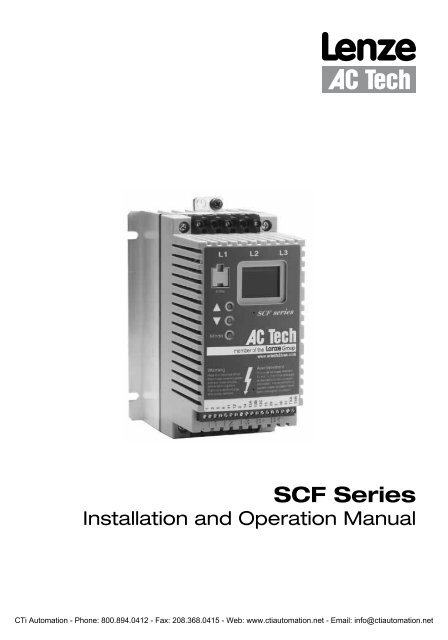
<strong>SCF</strong> <strong>Series</strong><br />
Installation and Operation <strong>Manual</strong><br />
<strong>CTi</strong> <strong>Automation</strong> - Phone: 800.894.0412 - Fax: 208.368.0415 - Web: www.ctiautomation.net - Email: info@ctiautomation.net
THE <strong>SCF</strong> SUB-MICRO DRIVE<br />
ELECTRONIC<br />
PROGRAMMING<br />
MODULE (EPM)<br />
PROGRAMMING<br />
BUTTONS<br />
OUTPUT (MOTOR)<br />
TERMINALS<br />
INPUT POWER<br />
TERMINALS<br />
Safety Information<br />
3-DIGIT LED<br />
DISPLAY<br />
CONTROL<br />
TERMINAL<br />
STRIP<br />
DC BUS<br />
TERMINALS<br />
All safety information given in these Operating Instruction have the same layout:<br />
Signal Word! (characterizes the severity of the danger)<br />
Note (describes the danger and informs on how to proceed)<br />
Icon Signal Words<br />
Warning of DANGER! Warns of impending danger.<br />
hazardous<br />
electrical<br />
voltage<br />
Consequences if disregarded:<br />
Death or severe injuries.<br />
Warning of<br />
a general<br />
danger<br />
Warning of<br />
damage to<br />
equipment<br />
WARNING! Warns of potential, very hazardous situations.<br />
Consequences if disregarded:<br />
Death or severe injuries.<br />
STOP! Warns of potential damage to material and<br />
equipment.<br />
Consequences if disregarded:<br />
Damage to the controller/drive or its environment.<br />
Information Note Designates a general, useful note.<br />
If you observe it, handling the controller/drive<br />
system is made easier.<br />
<strong>CTi</strong> <strong>Automation</strong> - Phone: 800.894.0412 - Fax: 208.368.0415 - Web: www.ctiautomation.net - Email: info@ctiautomation.net
Table of Contents<br />
1.0 GENERAL ........................................................................................2<br />
2.0 <strong>SCF</strong> DIMENSIONS ..........................................................................4<br />
3.0 <strong>SCF</strong> MODEL DESIGNATION CODE ...............................................7<br />
4.0 <strong>SCF</strong> SPECIFICATIONS ...................................................................8<br />
5.0 <strong>SCF</strong> RATINGS .................................................................................9<br />
6.0 INSTALLATION ..............................................................................11<br />
7.0 INPUT <strong>AC</strong> POWER REQUIREMENTS ..........................................12<br />
8.0 POWER WIRING ...........................................................................15<br />
9.0 <strong>SCF</strong> POWER WIRING DIAGRAM .................................................16<br />
10.0 CONTROL WIRING .......................................................................17<br />
11.0 <strong>SCF</strong> CONTROL WIRING DIAGRAMS ...........................................20<br />
12.0 INITIAL POWER UP AND MOTOR ROTATION ............................25<br />
13.0 PROGRAMMING THE <strong>SCF</strong> DRIVE ...............................................26<br />
14.0 PARAMETER MENU .....................................................................30<br />
15.0 DESCRIPTION OF PARAMETERS ...............................................33<br />
16.0 TROUBLESHOOTING ...................................................................48<br />
17.0 <strong>SCF</strong> DISPLAY MESSAGES ...........................................................50<br />
APPENDIX A - THROUGH-HOLE MOUNT OPTION ....................52<br />
APPENDIX B - PI SETPOINT CONTROL OPTION .......................56<br />
SF01U 1<br />
<strong>CTi</strong> <strong>Automation</strong> - Phone: 800.894.0412 - Fax: 208.368.0415 - Web: www.ctiautomation.net - Email: info@ctiautomation.net
1.0 GENERAL<br />
1.1 PRODUCTS COVERED IN THIS MANUAL<br />
This manual covers the Lenze <strong>AC</strong> <strong>Tech</strong> <strong>SCF</strong> <strong>Series</strong> Variable Frequency Drive.<br />
1.2<br />
WARRANTY<br />
Lenze <strong>AC</strong> <strong>Tech</strong> Corporation warrants the <strong>SCF</strong> <strong>Series</strong> <strong>AC</strong> motor control to be free of defects<br />
in material and workmanship for a period 24 months from date of shipment from Lenze <strong>AC</strong><br />
<strong>Tech</strong>'s factory. If an <strong>SCF</strong> motor control, under normal use, becomes defective within the<br />
stated warranty time period, contact Lenze <strong>AC</strong> <strong>Tech</strong>'s Service Department for instructions on<br />
obtaining a warranty replacement unit. Lenze <strong>AC</strong> <strong>Tech</strong> Corporation reserves the right to make<br />
the final determination as to the validity of a warranty claim, and sole obligation is to repair<br />
or replace only components which have been rendered defective due to faulty material or<br />
workmanship. No warranty claim will be accepted for components which have been damaged<br />
due to mishandling, improper installation, unauthorized repair and/or alteration of the product,<br />
operation in excess of design specifications or other misuse, or improper maintenance.<br />
Lenze <strong>AC</strong> <strong>Tech</strong> Corporation makes no warranty that its products are compatible with any<br />
other equipment, or to any specific application, to which they may be applied and shall not be<br />
held liable for any other consequential damage or injury arising from the use of its products.<br />
This warranty is in lieu of all other warranties, expressed or implied. No other person,<br />
firm or corporation is authorized to assume, for Lenze <strong>AC</strong> <strong>Tech</strong> Corporation, any other<br />
liability in connection with the demonstration or sale of its products.<br />
1.4 RECEIVING<br />
Inspect all cartons for damage which may have occurred during shipping. Carefully unpack<br />
equipment and inspect thoroughly for damage or shortage. Report any damage to carrier and/or<br />
shortages to supplier. All major components and connections should be examined for damage<br />
and tightness, with special attention given to PC boards, plugs, knobs and switches.<br />
1.5 SAFETY INFORMATION<br />
GENERAL<br />
Some parts of Lenze <strong>AC</strong> <strong>Tech</strong> controllers can be electrically live and some surfaces can be hot.<br />
Non-authorized removal of the required cover, inappropriate use, and incorrect installation or<br />
operation creates the risk of severe injury to personnel or damage to equipment.<br />
All operations concerning transport, installation, and commissioning as well as maintenance<br />
must be carried out by qualified, skilled personnel who are familiar with the installation,<br />
assembly, commissioning, and operation of variable frequency drives and the application for<br />
which it is being used.<br />
INSTALLATION<br />
Ensure proper handling and avoid excessive mechanical stress. Do not bend any components<br />
and do not change any insulation distances during transport, handling, installation or<br />
maintenance.<br />
2 SF01U<br />
<strong>CTi</strong> <strong>Automation</strong> - Phone: 800.894.0412 - Fax: 208.368.0415 - Web: www.ctiautomation.net - Email: info@ctiautomation.net
Do not touch any electronic components or contacts. This drive contains electrostatically<br />
sensitive components, which can easily be damaged by inappropriate handling. Static control<br />
precautions must be adhered to during installation, testing, servicing and repairing of this<br />
drive and associated options. Component damage may result if proper procedures are not<br />
followed.<br />
This drive has been tested by Underwriters Laboratory (UL) and is an approved component<br />
in compliance with UL508 Safety Standard.<br />
• Suitable for use on a circuit as described in Section 7.0 of this manual.<br />
• Use minimum 75 °C copper wire only.<br />
Warnings! • Shall be installed in a pollution degree 2 macro-environment.<br />
This drive must be installed and configured in accordance with both national and international<br />
standards. Local codes and regulations take precedence over recommendations provided in<br />
this and other Lenze <strong>AC</strong> <strong>Tech</strong> documentation.<br />
The <strong>SCF</strong> drive is considered a component for integration into a machine or process. It is neither<br />
a machine nor a device ready for use in accordance with European directives (reference<br />
machinery directive and electromagnetic compatibility directive). It is the responsibility of the<br />
end user to ensure that the machine meets the applicable standards.<br />
ELECTRICAL CONNECTION<br />
When working on live drive controllers, applicable national safety regulations must be<br />
observed.<br />
The electrical installation must be carried out according to the appropriate regulations (e.g.<br />
cable cross-sections, fuses, protective earth [PE] connection). While this document does make<br />
recommendations in regards to these items, national and local codes must be adhered to.<br />
The documentation contains information about installation in compliance with EMC (shielding,<br />
grounding, filters and cables). These notes must also be observed for CE-marked controllers.<br />
The manufacturer of the system or machine is responsible for compliance with the required<br />
limit values demanded by EMC legislation.<br />
APPLICATION<br />
The drive must not be used as a safety device for machines where there is a risk of personal injury<br />
or material damage. Emergency Stops, over-speed protection, acceleration and deceleration<br />
limits, etc must be made by other devices to ensure operation under all conditions.<br />
The drive does feature many protection devices which are aimed at protecting the drive<br />
and the driven equipment by generating a fault and shutting the drive and motor down by<br />
removing power. Mains power variances can also result in shutdown of the drive. When the<br />
fault condition disappears or is cleared, the drive can be configured to automatically restart,<br />
it is the responsibility of the user and/or OEM and/or integrator to ensure that the drive is<br />
configured for safe operation.<br />
1.6 CUSTOMER MODIFICATION<br />
Lenze <strong>AC</strong> <strong>Tech</strong> Corporation, its sales representatives and distributors, welcome the opportunity<br />
to assist our customers in applying our products. Many customizing options are available to aid<br />
in this function. Lenze <strong>AC</strong> <strong>Tech</strong> Corporation cannot assume responsibility for any modifications<br />
not authorized by its engineering department<br />
SF01U 3<br />
<strong>CTi</strong> <strong>Automation</strong> - Phone: 800.894.0412 - Fax: 208.368.0415 - Web: www.ctiautomation.net - Email: info@ctiautomation.net
2.0 <strong>SCF</strong> DIMENSIONS<br />
H<br />
D<br />
HP kW<br />
INPUT<br />
VOLTAGE<br />
MODEL H W D P R<br />
0.25 0.18 208 / 240 SF203Y 5.75 (146) 2.88 (73) 3.94 (100) 0.80 (20) 4.37 (111)<br />
0.5 0.37<br />
1 0.75<br />
1.5 1.1<br />
2 1.5<br />
W<br />
R<br />
P<br />
S<br />
Dia. Slot<br />
Mounting Tab Detail<br />
If R < 6.30" (160)<br />
S = 0.19" (5)<br />
T = 0.38" (10)<br />
U = 0.18" (5)<br />
V = 0.66" (17)<br />
If R = 6.30" (160)<br />
S = 0.28" (7)<br />
T = 0.50" (13)<br />
U = 0.24" (6)<br />
V = 0.90" (23)<br />
208 / 240 SF205Y 5.75 (146) 2.88 (73) 3.94 (100) 0.80 (20) 4.37 (111)<br />
400 / 480 SF405 5.75 (146) 2.88 (73) 3.94 (100) 0.80 (20) 4.37 (111)<br />
208 / 240 SF210Y 5.75 (146) 2.88 (73) 4.74 (120) 1.60 (41) 4.37 (111)<br />
208 / 240 SF210 5.75 (146) 2.88 (73) 4.74 (120) 1.60 (41) 4.37 (111)<br />
400 / 480 SF410 5.75 (146) 2.88 (73) 4.74 (120) 1.60 (41) 4.37 (111)<br />
480 / 590 SF510 5.75 (146) 2.88 (73) 4.74 (120) 1.60 (41) 4.37 (111)<br />
208 / 240 SF215Y 5.75 (146) 3.76 (96) 5.24 (133) 1.90 (48) 4.37 (111)<br />
208 / 240 SF215 5.75 (146) 2.88 (73) 5.74 (146) 2.60 (66) 4.37 (111)<br />
400 / 480 SF415 5.75 (146) 2.88 (73) 5.74 (146) 2.60 (66) 4.37 (111)<br />
208 / 240 SF220Y 5.75 (146) 3.76 (96) 6.74 (171) 3.40 (86) 4.37 (111)<br />
208 / 240 SF220 5.75 (146) 2.88 (73) 5.74 (146) 2.60 (66) 3.06 (78)<br />
400 / 480 SF420 5.75 (146) 2.88 (73) 5.74 (146) 2.60 (66) 4.37 (111)<br />
480 / 590 SF520 5.75 (146) 2.88 (73) 5.74 (146) 2.60 (66) 4.37 (111)<br />
4 SF01U<br />
<strong>CTi</strong> <strong>Automation</strong> - Phone: 800.894.0412 - Fax: 208.368.0415 - Web: www.ctiautomation.net - Email: info@ctiautomation.net<br />
T<br />
U<br />
V
HP kW<br />
3 2.2<br />
5 3.7<br />
7.5 5.5<br />
10 7.5<br />
15 11<br />
20 15<br />
25 18.5<br />
INPUT<br />
VOLTAGE<br />
MODEL H W D P R<br />
208 / 240 SF230Y 5.75 (146) 3.76 (96) 6.74 (171) 3.40 (86) 3.25 (83)<br />
208 / 240 SF230 5.75 (146) 2.88 (73) 5.74 (146) 2.60 (66) 3.06 (78)<br />
400 / 480 SF430 5.75 (146) 2.88 (73) 5.74 (146) 2.60 (66) 3.06 (78)<br />
480 / 590 SF530 5.75 (146) 3.76 (96) 6.74 (171) 3.40 (86) 4.37 (111)<br />
208 / 240 SF250Y 7.75 (197) 5.02 (128) 7.18 (182) 3.40 (86) 4.81 (122)<br />
208 / 240 SF250 5.75 (146) 3.76 (96) 6.74 (171) 3.40 (86) 3.25 (83)<br />
400 / 480 SF450 5.75 (146) 3.76 (96) 6.74 (171) 3.40 (86) 3.25 (83)<br />
480 / 590 SF550 5.75 (146) 3.76 (96) 6.74 (171) 3.40 (86) 3.25 (83)<br />
208 / 240 SF275 7.75 (197) 5.02 (128) 7.18 (182) 3.40 (86) 4.81 (122)<br />
400 / 480 SF475 7.75 (197) 5.02 (128) 7.18 (182) 3.40 (86) 4.81 (122)<br />
480 / 590 SF575 7.75 (197) 5.02 (128) 7.18 (182) 3.40 (86) 4.81 (122)<br />
208 / 240 SF2100 7.75 (197) 5.02 (128) 7.18 (182) 3.40 (86) 4.81 (122)<br />
400 / 480 SF4100 7.75 (197) 5.02 (128) 7.18 (182) 3.40 (86) 4.81 (122)<br />
480 / 590 SF5100 7.75 (197) 5.02 (128) 7.18 (182) 3.40 (86) 4.81 (122)<br />
208 / 240 SF2150 9.75 (248) 6.68 (170) 8.00 (203) 3.60 (91) 6.30 (160)<br />
400 / 480 SF4150 9.75 (248) 6.68 (170) 8.00 (203) 3.60 (91) 6.30 (160)<br />
480 / 590 SF5150 9.75 (248) 6.68 (170) 8.00 (203) 3.60 (91) 6.30 (160)<br />
208 / 240 SF2200 9.75 (248) 6.68 (170) 8.00 (203) 3.60 (91) 6.30 (160)<br />
400 / 480 SF4200 9.75 (248) 6.68 (170) 8.00 (203) 3.60 (91) 6.30 (160)<br />
480 / 590 SF5200 9.75 (248) 6.68 (170) 8.00 (203) 3.60 (91) 6.30 (160)<br />
400 / 480 SF4250 9.75 (248) 6.68 (170) 8.00 (203) 3.60 (91) 6.30 (160)<br />
480 / 590 SF5250 9.75 (248) 6.68 (170) 8.00 (203) 3.60 (91) 6.30 (160)<br />
30 22 400 / 480 SF4300 9.75 (248) 6.68 (170) 8.00 (203) 3.60 (91) 6.30 (160)<br />
SF01U 5<br />
<strong>CTi</strong> <strong>Automation</strong> - Phone: 800.894.0412 - Fax: 208.368.0415 - Web: www.ctiautomation.net - Email: info@ctiautomation.net
2.1 <strong>SCF</strong> THROUGH-HOLE MOUNT DIMENSIONS<br />
H<br />
HP kW<br />
1 0.75<br />
1.5 1.1<br />
2 1.5<br />
3 2.2<br />
5 3.7<br />
7.5 5.5<br />
W<br />
INPUT<br />
VOLTAGE<br />
6 SF01U<br />
<strong>CTi</strong> <strong>Automation</strong> - Phone: 800.894.0412 - Fax: 208.368.0415 - Web: www.ctiautomation.net - Email: info@ctiautomation.net<br />
D<br />
MODEL H W D P<br />
208 / 240 SF210YF 7.72 (196) 6.80 (173) 4.55 (116) 1.20 (30)<br />
208 / 240 SF210F 7.72 (196) 6.80 (173) 4.55 (116) 1.20 (30)<br />
400 / 480 SF410F 7.72 (196) 6.80 (173) 4.55 (116) 1.20 (30)<br />
480 / 590 SF510F 7.72 (196) 6.80 (173) 4.55 (116) 1.20 (30)<br />
208 / 240 SF215YF 7.72 (196) 6.80 (173) 4.75 (121) 1.20 (30)<br />
208 / 240 SF215F 7.72 (196) 6.80 (173) 4.55 (116) 1.20 (30)<br />
400 / 480 SF415F 7.72 (196) 6.80 (173) 4.55 (116) 1.20 (30)<br />
208 / 240 SF220YF 7.72 (196) 6.80 (173) 4.75 (121) 1.20 (30)<br />
208 / 240 SF220F 7.72 (196) 6.80 (173) 4.55 (116) 1.20 (30)<br />
400 / 480 SF420F 7.72 (196) 6.80 (173) 4.55 (116) 1.20 (30)<br />
480 / 590 SF520F 7.72 (196) 6.80 (173) 4.55 (116) 1.20 (30)<br />
208 / 240 SF230YF 7.72 (196) 8.54 (217) 5.30 (135) 1.75 (44)<br />
208 / 240 SF230F 7.72 (196) 8.54 (217) 5.10 (130) 1.75 (44)<br />
400 / 480 SF430F 7.72 (196) 8.54 (217) 5.10 (130) 1.75 (44)<br />
480 / 590 SF530F 7.72 (196) 8.54 (217) 5.30 (135) 1.75 (44)<br />
208 / 240 SF250YF 9.59 (244) 11.14 (283) 7.65 (194) 3.60 (91)<br />
208 / 240 SF250F 7.72 (196) 8.54 (217) 6.30 (160) 2.75 (70)<br />
400 / 480 SF450F 7.72 (196) 8.54 (217) 6.30 (160) 2.75 (70)<br />
480 / 590 SF550F 7.72 (196) 8.54 (217) 6.30 (160) 2.75 (70)<br />
208 / 240 SF275F 11.59 (294) 11.14 (283) 7.65 (194) 3.60 (91)<br />
400 / 480 SF475F 9.59 (244) 11.14 (283) 7.65 (194) 3.60 (91)<br />
480 / 590 SF575F 9.59 (244) 11.14 (283) 7.65 (194) 3.60 (91)<br />
P
HP kW<br />
10 7.5<br />
15 11<br />
20 15<br />
25 18.5<br />
INPUT<br />
VOLTAGE<br />
MODEL H W D P<br />
208 / 240 SF2100F 15.59 (396) 11.14 (283) 7.65 (194) 3.60 (91)<br />
400 / 480 SF4100F 11.59 (294) 11.14 (283) 7.65 (194) 3.60 (91)<br />
480 / 590 SF5100F 11.59 (294) 11.14 (283) 7.65 (194) 3.60 (91)<br />
208 / 240 SF2150F 18.09 (459) 11.14 (283) 8.29 (211) 3.60 (91)<br />
400 / 480 SF4150F 15.59 (396) 11.14 (283) 8.29 (211) 3.60 (91)<br />
480 / 590 SF5150F 15.59 (396) 11.14 (283) 8.29 (211) 3.60 (91)<br />
400 / 480 SF4200F 18.09 (459) 11.14 (283) 8.29 (211) 3.60 (91)<br />
480 / 590 SF5200F 18.09 (459) 11.14 (283) 8.29 (211) 3.60 (91)<br />
400 / 480 SF4250F 28.50 (724) 10.34 (263) 8.39 (213) 3.70 (94)<br />
480 / 590 SF5250F 28.50 (724) 10.34 (263) 8.39 (213) 3.70 (94)<br />
NOTE: Refer to Appendix A for mounting template dimensions for the Through-hole Mount option.<br />
3.0 <strong>SCF</strong> MODEL DESIGNATION CODE<br />
The <strong>SCF</strong> model number gives a full description of the basic drive unit (see example below).<br />
EXAMPLE: SF210Y (<strong>SCF</strong> <strong>Series</strong>, 208/240 Vac, 1 HP, single or three phase input)<br />
SF 2 10 Y<br />
<strong>Series</strong>:<br />
SF = <strong>SCF</strong> <strong>Series</strong> Variable Speed <strong>AC</strong> Motor Drive<br />
Input Voltage:<br />
2 = 208/240 Vac (For 208, 230, and 240 Vac; 50 or 60 Hz)<br />
4 = 400/480 Vac (For 380, 415, 440, 460 and 480 Vac; 50 or 60 Hz)<br />
5 = 480/590 Vac (For 440, 460, 480, 575 and 600 Vac; 50 or 60 Hz)<br />
Rating:<br />
03 = ¼ HP (0.20 kW) 30 = 3 HP (2.2 kW) 200 = 20 HP (15 kW)<br />
05 = ½ HP (0.37 kW) 50 = 5 HP (4.0 kW) 250 = 25 HP (18.5 kW)<br />
10 = 1 HP (0.75 kW) 75 = 7½ HP (5.5 kW) 300 = 30 HP (22 kW)<br />
15 = 1½ HP (1.1 kW) 100 = 10 HP (7.5 kW)<br />
20 = 2 HP (1.5 kW) 150 = 15 HP (11 kW)<br />
Input Phase:<br />
Y = Single or three phase input.<br />
No character indicates three phase input only<br />
Mounting Style:<br />
F = Through-hole mount with special heatsink<br />
F1 = Through-hole mount without heatsink (customer supplies heatsink)<br />
No character indicates panel or DIN rail mounting<br />
Application Specific Options:<br />
P = PI (setpoint control) software<br />
V = High Frequency Output - up to 1000 Hz<br />
SF01U 7<br />
<strong>CTi</strong> <strong>Automation</strong> - Phone: 800.894.0412 - Fax: 208.368.0415 - Web: www.ctiautomation.net - Email: info@ctiautomation.net
4.0 <strong>SCF</strong> SPECIFICATIONS<br />
Storage Temperature -20° to 70° C<br />
Ambient Operating Temperature 0° to 50° C (derate 2.5% per °C above 50°)<br />
Ambient Humidity < 95% (non-condensing)<br />
Maximum Altitude 3300 ft (1000 m) above sea level (derate 5% per additional 3300 ft)<br />
Input Line Voltages 208/240 Vac, 400/480 Vac, 480/590 Vac<br />
Input Voltage Tolerance +10%, -15%<br />
Input Frequency Tolerance 48 to 62 Hz<br />
Output Wave Form Sine Coded PWM<br />
Output Frequency 0 - 240 Hz (consult factory for higher output frequencies)<br />
Carrier Frequency 4 kHz to 10 kHz (over 6 kHz requires derating; see parameter P02)<br />
Service Factor 1.00 (up to 6 kHz carrier; derate above 6 kHz; see parameter P02)<br />
Efficiency Up to 98%<br />
Power Factor (displacement) 0.96 or better<br />
Overload Current Capacity 150% for 60 seconds, 180% for 30 seconds<br />
Speed Reference Follower 0-10 VDC, 4-20 mA<br />
Control Voltage 15 VDC<br />
Power Supply for Auxiliary Relays 50 mA at 12 VDC<br />
Analog Output 0 - 10 VDC or 2 - 10 VDC: Proportional to frequency and load<br />
Digital Outputs Open-collector outputs: 50 mA at 30 VDC<br />
8 SF01U<br />
<strong>CTi</strong> <strong>Automation</strong> - Phone: 800.894.0412 - Fax: 208.368.0415 - Web: www.ctiautomation.net - Email: info@ctiautomation.net
5.0 <strong>SCF</strong> RATINGS<br />
MODEL<br />
NUMBER<br />
(NOTE 1)<br />
FOR MOTORS<br />
RATED<br />
HP kW<br />
INPUT<br />
PHASE<br />
INPUT (50-60 Hz) OUTPUT HEAT LOSS<br />
CURRENT<br />
(AMPS)<br />
POWER<br />
(kVA)<br />
CURRENT<br />
(AMPS)<br />
(WATTS)<br />
(NOTE 5)<br />
SF200Y SERIES (NOTE 2) 208 / 240 Vac 0 - 200 / 230 Vac STD THRU<br />
SF203Y 0.25 0.20 1 3.6 / 3.2 0.76 1.6 / 1.4 19 N/A<br />
SF203Y 0.25 0.20 3 1.9 / 1.7 0.71 1.6 / 1.4 19 N/A<br />
SF205Y 0.5 0.37 1 5.4 / 4.7 1.2 2.5 / 2.2 26 N/A<br />
SF205Y 0.5 0.37 3 3.1 / 2.7 1.1 2.5 / 2.2 26 N/A<br />
SF210Y 1 0.75 1 10.6 / 9.2 2.2 4.8 / 4.2 49 18<br />
SF210Y 1 0.75 3 5.8 / 5.1 2.1 4.8 / 4.2 49 18<br />
SF215Y 1.5 1.1 1 13.9 / 12.0 2.9 6.9 / 6.0 82 23<br />
SF215Y 1.5 1.1 3 8.0 / 6.9 2.9 6.9 / 6.0 82 23<br />
SF220Y 2 1.5 1 14.8 / 12.9 3.1 7.8 / 6.8 86 26<br />
SF220Y 2 1.5 3 9.1 / 7.9 3.2 7.8 / 6.8 86 26<br />
SF230Y 3 2.2 1 19.7 / 17.1 4.1 11.0 / 9.6 130 29<br />
SF230Y 3 2.2 3 12.4 / 10.8 4.4 11.0 / 9.6 130 29<br />
SF250Y 5 3.7 1 29 / 26 6.1 17.5 / 15.2 212 40<br />
SF250Y 5 3.7 3 19.6 / 17.1 7.1 17.5 / 15.2 212 40<br />
SF200 SERIES (NOTE 2) 208 / 240 Vac 0 - 200 / 230 Vac<br />
SF210 1 0.75 3 5.8 / 5.1 2.1 4.8 / 4.2 41 11<br />
SF215 1.5 1.1 3 8.0 / 6.9 2.9 6.9 / 6.0 69 13<br />
SF220 2 1.5 3 9.1 / 7.9 3.3 7.8 / 6.8 78 15<br />
SF230 3 2.2 3 12.4 / 10.8 4.5 11.0 / 9.6 117 20<br />
SF250 5 3.7 3 19.6 / 17.1 7.1 17.5 / 15.2 187 22<br />
SF275 7.5 5.5 3 28 / 25 10.3 25 / 22 286 31<br />
SF2100 10 7.5 3 34 / 32 13.1 30 / 28 379 39<br />
SF2150 15 11 3 54 / 48 20.0 48 / 42 476 51<br />
SF2200 20 15 3 65 / 61 25.4 58 / 54 648 N/A<br />
NOTE 1: See Section 3.0 for model number breakdown.<br />
NOTE 2: The higher current ratings are for 208 Vac input and the lower current ratings are for 240 Vac input.<br />
NOTE 5: STD = standard unit; THRU = through-hole mount unit. Values are worst-case (not typical) for 6kHz carrier<br />
frequency at full speed and full load.<br />
SF01U 9<br />
<strong>CTi</strong> <strong>Automation</strong> - Phone: 800.894.0412 - Fax: 208.368.0415 - Web: www.ctiautomation.net - Email: info@ctiautomation.net
MODEL<br />
NUMBER<br />
(NOTE 1)<br />
FOR MOTORS<br />
RATED<br />
HP kW<br />
INPUT<br />
PHASE<br />
INPUT (50-60 Hz) OUTPUT HEAT LOSS<br />
CURRENT<br />
(AMPS)<br />
POWER<br />
(kVA)<br />
CURRENT<br />
(AMPS)<br />
(WATTS)<br />
(NOTE 5)<br />
SF400 SERIES (NOTE 3) 400 / 480 Vac 0 - 400 / 460 Vac STD THRU<br />
SF405 0.5 0.37 3 1.6 / 1.4 1.1 1.3 / 1.1 26 N/A<br />
SF410 1 0.75 3 2.9 / 2.5 2.1 2.4 / 2.1 40 12<br />
SF415 1.5 1.1 3 4.0 / 3.6 3.0 3.4 / 3.0 56 13<br />
SF420 2 1.5 3 4.6 / 4.0 3.3 3.9 / 3.4 67 14<br />
SF430 3 2.2 3 6.2 / 5.4 4.5 5.5 / 4.8 100 19<br />
SF450 5 3.7 3 9.8 / 8.6 7.1 8.7 / 7.6 168 22<br />
SF475 7.5 5.5 3 14.2 / 12.4 10.3 12.6 / 11.0 254 29<br />
SF4100 10 7.5 3 18.1 / 15.8 13.1 16.1 / 14.0 310 37<br />
SF4150 15 11 3 27 / 24 20.0 24 / 21 390 42<br />
SF4200 20 15 3 35 / 31 25.8 31 / 27 530 57<br />
SF4250 25 18.5 3 44 / 38 31.6 39 / 34 648 72<br />
SF4300 30 22 3 52 / 45 37.4 46 / 40 770 N/A<br />
SF500 SERIES (NOTE 4) 480 / 590 Vac 0 - 460 / 575 Vac<br />
SF510 1 0.75 3 2.2 / 2.0 1.9 / 2.0 1.9 / 1.7 40 12<br />
SF520 2 1.5 3 4.0 / 3.5 3.3 / 3.6 3.4 / 3.0 67 13<br />
SF530 3 2.2 3 4.7 / 4.7 3.9 / 4.8 4.2 / 4.2 100 14<br />
SF550 5 3.7 3 7.4 / 7.4 6.1 / 7.5 6.6 / 6.6 168 19<br />
SF575 7.5 5.5 3 11.2 / 11.2 9.3 / 11.4 9.9 / 9.9 254 29<br />
SF5100 10 7.5 3 13.7 / 13.7 11.4 / 14.0 12.2 / 12.2 310 37<br />
SF5150 15 11 3 22 / 22 18.3 / 22.5 19.0 / 19.0 390 42<br />
SF5200 20 15 3 27 / 27 22.4 / 27.6 24 / 24 530 57<br />
SF5250 25 18.5 3 31 / 31 25.8 / 31.7 27 / 27 648 72<br />
NOTE 1: See Section 3.0 for model number breakdown.<br />
NOTE 3: The higher current ratings are for 400 Vac input and the lower current ratings are for 480 Vac input.<br />
NOTE 4: The higher current ratings are for 480 Vac input and the lower current ratings are for 590 Vac input.<br />
NOTE 5: STD = standard unit; THRU = through-hole mount unit. Values are worst-case (not typical) for 6kHz carrier<br />
frequency at full speed and full load.<br />
10 SF01U<br />
<strong>CTi</strong> <strong>Automation</strong> - Phone: 800.894.0412 - Fax: 208.368.0415 - Web: www.ctiautomation.net - Email: info@ctiautomation.net
6.0 INSTALLATION<br />
NOTE<br />
<strong>SCF</strong> <strong>Series</strong> drives are intended for inclusion within other equipment, by<br />
professional electrical installers according to EN 61000-3-2. They are not<br />
intended for stand-alone operation<br />
WARNING!<br />
<strong>Drives</strong> must NOT be installed where subjected to adverse environmental<br />
conditions such as: combustible, oily, or hazardous vapors or dust; excessive<br />
moisture or dirt; vibration; excessive ambient temperatures. Consult Lenze<br />
<strong>AC</strong> <strong>Tech</strong> for more information on the suitability of a drive to a particular<br />
environment.<br />
<strong>SCF</strong> models are suitable for UL pollution degree 2 environment only, and MUST be installed in<br />
an electrical enclosure which will provide complete mechanical protection and will maintain the<br />
internal temperature within the drive’s ambient operating temperature rating. All drive models<br />
MUST be mounted in a vertical position for proper heatsink cooling.<br />
Maintain a minimum spacing around the drive of at least 1 inch (25 mm) on each side and<br />
2 inches (50 mm) on the top and bottom for units rated up to 5 HP (3.7 kW). For units rated<br />
7.5 - 30 HP (5.5 - 22 kW), maintain at least 2 inches (50 mm) on each side and 4 inches (100<br />
mm) on the top and bottom. Allow more spacing if the drive is mounted next to other heatproducing<br />
equipment. Do not mount drives above other drives or heat producing equipment.<br />
Fans or blowers should be used to insure proper cooling in tight quarters.<br />
In order to properly size an enclosure, the heat generated by the drive(s) must be known. Refer<br />
to the HEAT LOSS columns in Section 5.0 - <strong>SCF</strong> RATINGS. The STD column is for standard<br />
units, and the THRU column is for through-hole mount units (drives with the through-hole<br />
mount option still generate some heat inside the enclosure that must be taken into account).<br />
An enclosure manufacturer can then determine the required enclosure size based on the total<br />
heat generated inside the enclosure (from the drive(s) and other heat sources), the maximum<br />
allowable temperature inside the enclosure, the maximum ambient temperature outside the<br />
enclosure, and the enclosure properties.<br />
The <strong>SCF</strong> <strong>Series</strong> is UL approved for solid state motor overload protection. Therefore, a separate<br />
thermal overload relay is not required for single motor applications.<br />
6.1 INSTALLATION AFTER A LONG PERIOD OF STORAGE<br />
STOP!<br />
Severe damage to the drive can result if it is operated after a long period of<br />
storage or inactivity without reforming the DC bus capacitors!<br />
If input power has not been applied to the drive for a period of time exceeding three years<br />
(due to storage, etc), the electrolytic DC bus capacitors within the drive can change internally,<br />
resulting in excessive leakage current. This can result in premature failure of the capacitors<br />
if the drive is operated after such a long period of inactivity or storage.<br />
In order to reform the capacitors and prepare the drive for operation after a long period of<br />
inactivity, apply input power to the drive for 8 hours prior to actually operating the motor.<br />
SF01U 11<br />
<strong>CTi</strong> <strong>Automation</strong> - Phone: 800.894.0412 - Fax: 208.368.0415 - Web: www.ctiautomation.net - Email: info@ctiautomation.net
6.2 EXPLOSION PROOF APPLICATIONS<br />
Explosion proof motors that are not rated for inverter use lose their certification when used<br />
for variable speed. Due to the many areas of liability that may be encountered when dealing<br />
with these applications, the following statement of policy applies:<br />
“Lenze <strong>AC</strong> <strong>Tech</strong> Corporation inverter products are sold with no warranty of fitness for a<br />
particular purpose or warranty of suitability for use with explosion proof motors. Lenze <strong>AC</strong> <strong>Tech</strong><br />
Corporation accepts no responsibility for any direct, incidental or consequential loss, cost, or<br />
damage that may arise through the use of its <strong>AC</strong> inverter products in these applications. The<br />
purchaser expressly agrees to assume all risk of any loss, cost, or damage that may arise<br />
from such application."<br />
7.0 INPUT <strong>AC</strong> POWER REQUIREMENTS<br />
DANGER!<br />
Hazard of electrical shock! Capacitors retain charge after power is removed.<br />
Disconnect incoming power and wait until the voltage between terminals B+<br />
and B- is 0 VDC before servicing the drive.<br />
The input voltage must match the nameplate voltage rating of the drive. Voltage fluctuation<br />
must not vary by greater than 10% overvoltage or 15% undervoltage.<br />
NOTE<br />
<strong>Drives</strong> with dual input voltage ratings must be programmed for the proper<br />
supply voltage (refer to Parameter 01 - LINE VOLTAGE SELECTION in<br />
Section 15.0 - DESCRIPTION OF PARAMETERS).<br />
The drive is suitable for use on a circuit capable of delivering not more than 5,000 RMS<br />
symmetrical amperes at 5 HP (3.7 kW) and below, and 18,000 RMS symmetrical amperes at<br />
7.5 HP (5.5 kW) and above, at the drive’s rated voltage.<br />
If the kVA rating of the <strong>AC</strong> supply transformer is greater than 10 times the input kVA rating<br />
of the drive(s), an isolation transformer or 2-3% input line reactor must be added to the line<br />
side of the drive(s).<br />
Three phase voltage imbalance must be less than 2.0% phase to phase. Excessive phase to<br />
phase imbalance can cause severe damage to the drive’s power components.<br />
Motor voltage should match line voltage in normal applications. The drive’s maximum output<br />
voltage will equal the input voltage. Use extreme caution when using a motor with a voltage<br />
rating which is different from the input line voltage.<br />
12 SF01U<br />
<strong>CTi</strong> <strong>Automation</strong> - Phone: 800.894.0412 - Fax: 208.368.0415 - Web: www.ctiautomation.net - Email: info@ctiautomation.net
7.1 INPUT VOLTAGE RATINGS<br />
SF200 <strong>Series</strong> drives are rated for 208/240 Vac, three phase, 50-60 Hz input. The drive will<br />
function with input voltages of 208 to 240 Vac (+ 10%, - 15%), at 48 to 62 Hz.<br />
SF200Y <strong>Series</strong> drives are rated for 208/240 Vac, single or three phase, 50-60 Hz input. The<br />
drive will function with input voltage of 208 to 240 Vac (+10%, -15%), at 48 to 62 Hz.<br />
SF400 <strong>Series</strong> drives are rated for 400/480 Vac three phase, 50-60 Hz input. The drive will<br />
function with input voltages of 400 to 480 Vac (+ 10%, - 15%), at 48 to 62 Hz.<br />
SF500 <strong>Series</strong> drives are rated for 480/590 Vac, three phase, 50-60 Hz input, and will function<br />
with input voltages of 480 to 590 Vac (+ 10%, - 15%), at 48 to 62 Hz.<br />
NOTE<br />
Parameter 01 - LINE VOLTAGE SELECTION must be programmed<br />
according to the applied input voltage. See Section 15.0 - DESCRIPTION<br />
OF PARAMETERS.<br />
7.2 INPUT FUSING AND DISCONNECT REQUIREMENTS<br />
A circuit breaker or a disconnect switch with fuses must be provided in accordance with the<br />
National Electric Code (NEC) and all local codes. Refer to the following tables for proper fuse/<br />
circuit breaker ratings and wire sizes.<br />
INPUT FUSE & CIRCUIT BREAKER RATINGS<br />
208/240 Vac, 1 phase 208/240 Vac, 3 phase 400/480 Vac, 3 phase 480/590 Vac, 3 phase<br />
MODEL RATING MODEL RATING MODEL RATING MODEL RATING<br />
SF203Y 10 A SF203Y 10 A<br />
SF205Y 10 A SF205(Y) 10 A SF405 10 A<br />
SF210Y 15 A SF210(Y) 10 A SF410 10 A SF510 10 A<br />
SF215Y 20 A SF215(Y) 12 / 10 A SF415 10 A<br />
SF220Y 25 / 20 A SF220(Y) 15 / 12 A SF420 10 A SF520 10 A<br />
SF230Y 30 / 25 A SF230(Y) 20 / 15 A SF430 10 A SF530 10 A<br />
SF250Y 45 / 40 A SF250(Y) 30 / 25 A SF450 15 A SF550 12 A<br />
SF275 45 / 40 A SF475 20 A SF575 20 A<br />
SF2100 50 / 50 A SF4100 30 / 25 A SF5100 20 A<br />
SF2150 80 / 75 A SF4150 40 / 35 A SF5150 30 A<br />
SF2200 100 / 90 A SF4200 50 / 45 A SF5200 40 A<br />
SF4250 70 / 60 A SF5250 45 A<br />
SF4300 80 / 70 A<br />
NOTE<br />
• Applicable national and local electrical codes take precedence over<br />
recommendations in these tables.<br />
• Use UL Class CC fast-acting, current limiting type fuses. Select fuses with low<br />
I 2 T values, rated at 200,000 AIC. Recommended fuses are Bussman<br />
KTK-R, JJN, and JJS. Similar fuses with equivalent ratings by other<br />
manufacturers may also be acceptable.<br />
SF01U 13<br />
<strong>CTi</strong> <strong>Automation</strong> - Phone: 800.894.0412 - Fax: 208.368.0415 - Web: www.ctiautomation.net - Email: info@ctiautomation.net
WARNING!<br />
This product can cause a DC current in the protective conductor. Where a<br />
residual current device (RCD) is used for protection in case of direct or indirect<br />
contact, only an RCD of Type B is allowed on the supply side of this product.<br />
Otherwise, another protective measure shall be applied, such as separation<br />
from the environment by double or reinforced insulation, or isolation from the<br />
supply system by a transformer.<br />
Observe the following when using RCDs:<br />
1. Only install the RCD between the supply mains and drive controller.<br />
2. The RCD can be activated by:<br />
- capacitive leakage currents between the cable screens during operation<br />
(especially with long, screened motor cables)<br />
- connecting several drives to the mains at the same time<br />
- additional RFI filters<br />
7.3 INPUT WIRE SIZE REQUIREMENTS<br />
WIRE SIZE REQUIREMENTS<br />
208/240 Vac, 1 phase 208/240 Vac, 3 phase 400/480 Vac, 3 phase 480/590 Vac, 3 phase<br />
MODEL AWG mm2 MODEL AWG mm2 MODEL AWG mm2 MODEL AWG mm2 SF203Y 14 2.5 SF203Y 14 2.5<br />
SF205Y 14 2.5 SF205Y 14 2.5 SF405 14 2.5<br />
SF210Y 12 4.0 SF210(Y) 14 2.5 SF410 14 2.5 SF510 14 2.5<br />
SF215Y 12 4.0 SF215(Y) 14 2.5 SF415 14 2.5<br />
SF220Y 10 6.0 SF220(Y) 12 4.0 SF420 14 2.5 SF520 14 2.5<br />
SF230Y 10 6.0 SF230(Y) 10 6.0 SF430 14 2.5 SF530 14 2.5<br />
SF250Y 8 6.0 SF250(Y) 10 10 SF450 14 2.5 SF550 14 2.5<br />
SF275 10 10 SF475 12 4.0 SF575 14 2.5<br />
SF2100 8 10 SF4100 10 6.0 SF5100 12 4.0<br />
SF2150 6 16 SF4150 8 10 SF5150 10 6.0<br />
SF2200 4 25 SF4200 8 10 SF5200 8 10<br />
SF4250 6 16 SF5250 8 10<br />
SF4300 6 16<br />
7.4 INSTALLATION <strong>AC</strong>CORDING TO EMC REQUIREMENTS<br />
The <strong>SCF</strong> <strong>Series</strong> can be installed to meet the European standards for Electromagnetic<br />
Compatibility (EMC) requirements. These requirements govern the permissible electromagnetic<br />
emissions and immunity, both radiated and conducted, of a drive system.<br />
The EMC requirements apply to the final installation in its entirety, not to the individual<br />
components used. Because every installation is different, the recommended installation should<br />
follow these guidelines as a minimum. Additional equipment (such as ferrite core absorbers<br />
on power conductors) or alternative wiring practices may be required to meet conformance<br />
in some installations.<br />
14 SF01U<br />
<strong>CTi</strong> <strong>Automation</strong> - Phone: 800.894.0412 - Fax: 208.368.0415 - Web: www.ctiautomation.net - Email: info@ctiautomation.net
Filter: The input to the drive (or group of drives) must include a filter to reduce the electrical<br />
noise reflected back to the <strong>AC</strong> Line. The SCM can be installed to meet the industrial standards<br />
set by the EU, EN 61800-3 for conducted emissions and EN 55011 for radiated emissions to<br />
class A compliance when installed with an appropriately installed external line filter.<br />
EMC<br />
Compliance with EN 61800-3/A11<br />
Installation: Shielded cable must be used for all control and power cables<br />
and exposed wiring must be kept as short as possible.<br />
A Screen clamps<br />
B Control cable<br />
C Low-capacitance motor cable<br />
(core/core < 75 pF/m, core/screen < 150 pF/m)<br />
D Electrically conductive mounting plate<br />
E Filter<br />
8.0 POWER WIRING<br />
DANGER!<br />
Hazard of electrical shock! Capacitors retain charge after power is removed.<br />
Disconnect incoming power and wait until the voltage between terminals B+<br />
and B- is 0 VDC before servicing the drive.<br />
Note drive input and output current ratings and check applicable electrical codes for required<br />
wire type and size, grounding requirements, over-current protection, and incoming power<br />
disconnect, before wiring the drive. Size conservatively to minimize voltage drop.<br />
Refer to Section 9.0 - <strong>SCF</strong> POWER WIRING DIAGRAM for information on torque and wire<br />
stripping requirements for power wiring.<br />
Input fusing and a power disconnect switch or contactor MUST be wired in series with terminals<br />
L1, L2, and L3 for three phase input models. For 208/240 Vac single phase input models, use<br />
terminals L1 and L2. This disconnect must be used to power down the drive when servicing,<br />
or when the drive is not to be operated for a long period of time, but should not be used to<br />
start and stop the motor.<br />
Repetitive cycling of a disconnect or input contactor (more than once every two minutes)<br />
may cause damage to the drive.<br />
8.1 WIRING FOR SINGLE PHASE OR THREE PHASE INPUT<br />
If the drive is rated for single and three phase input (SF200Y models), wire to terminals L1 and<br />
L2 for single phase input, or wire to terminals L1, L2, and L3 for three phase input.<br />
If the drive is rated for three phase input, wire the input to terminals L1, L2, and L3.All three<br />
power output wires, from terminals T1, T2, and T3 to the motor, must be kept tightly bundled<br />
and run in a separate conduit away from all other power and control wiring.<br />
SF01U 15<br />
<strong>CTi</strong> <strong>Automation</strong> - Phone: 800.894.0412 - Fax: 208.368.0415 - Web: www.ctiautomation.net - Email: info@ctiautomation.net
It is not recommended to install contactors or disconnect switches between the drive and motor.<br />
Operating such devices while the drive is running can potentially cause damage to the drive's<br />
power components. If such a device is required, it should only be operated when the drive is<br />
in a STOP state. If there is potential for the device to be opened while the drive is running, the<br />
drive must be programmed for COAST to stop (see Parameter 4 - STOP METHOD), and an<br />
auxiliary contact on the device must be interlocked with the drive's run circuit. This will give<br />
the drive a stop command at the same time the device opens, and will not allow the drive to<br />
start again until the device is closed.<br />
9.0 <strong>SCF</strong> POWER WIRING DIAGRAM<br />
THREE PHASE INPUT<br />
(SF200, SF200Y, SF400,<br />
AND SF500 SERIES)<br />
L1 L2 L3<br />
0.25 - 5 HP<br />
(0.37 - 3.7 kW)<br />
4.5 lb-in / 0.5 Nm<br />
0.24 in / 6 mm<br />
7.5 - 10 HP<br />
(5.5 - 7.5 kW)<br />
10 lb-in / 1.2 Nm<br />
0.35 in / 9 mm<br />
SINGLE PHASE INPUT<br />
(SF200Y SERIES)<br />
L1 L2 L3<br />
15 - 30 HP<br />
(11 - 22 kW)<br />
18 lb-in / 2.0 Nm<br />
0.5 in / 13 mm<br />
OUTPUT (ALL SERIES)<br />
T1 T2 T3 B- B+<br />
3 PHASE<br />
<strong>AC</strong> MOTOR<br />
+<br />
DC BUS<br />
VOLTAGE<br />
STOP!<br />
DO NOT connect incoming <strong>AC</strong> power to output terminals T1, T2, T3, or<br />
terminals B+, B-! Severe damage to the drive will result.<br />
NOTE<br />
• WIRE AND GROUND IN <strong>AC</strong>CORDANCE WITH NEC OR CEC, AND ALL<br />
APPLICABLE LOCAL CODES.<br />
• Motor wires MUST be run in a separate steel conduit away from control<br />
wiring and incoming <strong>AC</strong> power wiring.<br />
• Do not install contactors between the drive and the motor without consulting<br />
<strong>AC</strong> <strong>Tech</strong>nology for more information. Failure to do so may result in drive<br />
damage.<br />
• Use only UL and CSA listed and approved wire.<br />
• Minimum wire voltage rating is 300 V for 120, 208, and 240 Vac systems,<br />
and 600 V for 400 and 480 Vac systems.<br />
• Wire gauge must be based on a minimum of 125% of the rated input/output<br />
current of the drive, and a minimum 75°C insulation rating. Use copper<br />
wire only.<br />
16 SF01U<br />
<strong>CTi</strong> <strong>Automation</strong> - Phone: 800.894.0412 - Fax: 208.368.0415 - Web: www.ctiautomation.net - Email: info@ctiautomation.net
10.0 CONTROL WIRING<br />
10.1 CONTROL WIRING VS. POWER WIRING<br />
External control wiring MUST be run in a separate conduit away from all other input and output<br />
power wiring. If control wiring is not kept separate from power wiring, electrical noise may be<br />
generated on the control wiring that will cause erratic drive behavior. Use twisted wires or<br />
shielded cable grounded at the drive chassis ONLY. Recommended control wire is Belden<br />
8760 (2-wire) or 8770 (3-wire), or equivalent.<br />
NOTE<br />
Control terminals provide basic isolation (insulation per EN 61800-5-1).<br />
Protection against contact can only be assured by additional measures e.g.<br />
supplemental insulation.<br />
Strip off 0.20 to 0.25 inches (5 to 6 mm) of insulation for control wiring, and torque the terminals<br />
to 2 lb-in (0.2 Nm). Be careful not to overtorque the terminals, as this will cause damage to<br />
the terminal strip. This is not covered under warranty and can only be repaired by replacing<br />
the control board.<br />
10.2 TB-2: CIRCUIT COMMON<br />
The TB-2 terminals are used as circuit common for the start/stop, forward/reverse, input<br />
select, local/remote, analog input, and analog output functions. There are three TB-2 terminals<br />
available on the terminal strip, and they are all internally connected to each other on the main<br />
control board. If necessary TB-2 may be connected to chassis ground.<br />
NOTE<br />
TB-2 must be connected to chassis ground when using serial<br />
communications.<br />
10.3 SURGE SUPPRESION ON RELAYS<br />
Current and voltage surges and spikes in the coils of contactors, relays, solenoids, etc, near<br />
or connected to the drive, can cause erratic drive operation. Therefore, a snubber circuit<br />
should be used on coils associated with the drive. For <strong>AC</strong> coils, snubbers should consist of<br />
a resistor and a capacitor in series across the coil. For DC coils, a free-wheeling or flyback<br />
diode should be placed across the coil. Snubbers are typically available from the manufacturer<br />
of the device.<br />
10.4 START/STOP CONTROL<br />
There are various control schemes that allow for 2-wire and 3-wire Start/Stop circuits. Refer<br />
to the wiring diagrams in Section 11.0 - <strong>SCF</strong> CONTROL WIRING DIAGRAMS<br />
10.5 SPEED REFERENCE SIGNALS<br />
The drive allows for three analog speed reference inputs:<br />
SPEED POT Connect the wiper of a speed pot to terminal TB-5, and connect the high and<br />
low end leads to terminals TB-6 and TB-2, respectively. The speed pot can<br />
be 2.5kΩ up to 10kΩ.<br />
0-10 VDC Wire the positive to terminal TB-5 and the negative to terminal TB-2. TB-5<br />
input impedance is 120 kilohms.<br />
4-20 mA Wire the positive to terminal TB-25 and the negative to terminal TB-2. TB-25<br />
input impedance is 100 ohms.<br />
SF01U 17<br />
<strong>CTi</strong> <strong>Automation</strong> - Phone: 800.894.0412 - Fax: 208.368.0415 - Web: www.ctiautomation.net - Email: info@ctiautomation.net
10.6 SPEED REFERENCE SELECTION<br />
If an analog speed reference input is used to control the drive speed, terminal TB-13A, 13B,<br />
or 13C (Parameter 10, 11, or 12) may be programmed as the input select for the desired<br />
analog input signal. When that TB-13 terminal is then closed to TB-2, the drive will follow the<br />
selected analog speed reference input.<br />
If an analog speed reference input is not selected on the terminal strip using TB-13A, 13B,<br />
or 13C, speed control will default to STANDARD mode, which is governed by the setting of<br />
Parameter 05 - STANDARD SPEED SOURCE. The STANDARD SPEED SOURCE can be<br />
the � and � buttons on the front of the drive, PRESET SPEED #1 (Parameter 31), a 0-10<br />
VDC signal, or a 4-20 mA signal.<br />
0 - 10 VDC and 4 - 20 mA INPUT SIGNALS<br />
TB-13A, TB-13B, and TB-13C can all be programmed to select a 0-10 VDC or 4-20 mA analog<br />
speed reference input.<br />
PRESET SPEEDS<br />
TB-13A can be programmed to select PRESET SPEED #1, TB-13B to select PRESET SPEED<br />
#2, and TB-13C to select PRESET SPEED #3. There are a total of seven preset speeds, which<br />
are activated by different combinations of contact closures between TB-13A, 13B, 13C and<br />
TB-2. Refer to Parameters 31-37 in Section 15.0 - DESCRIPTION OF PARAMETERS.<br />
JOG<br />
TB-13B can be programmed to select either JOG FORWARD or JOG REVERSE. The Jog<br />
speed is set by PRESET SPEED #2. Close TB-13B to TB-2 to JOG, and open the contact<br />
to STOP.<br />
WARNING!<br />
When operating in JOG mode, the STOP terminal (TB-1) and the STOP key<br />
(on the optional remote keypad) WILL NOT stop the drive. To stop the drive,<br />
remove the JOG command.<br />
JOG REVERSE will operate the drive in reverse rotation even if ROTATION<br />
DIRECTION (Parameter 17) is set to FORWARD ONLY<br />
NOTE<br />
If the drive is commanded to JOG while running, the drive will enter JOG<br />
mode and run at PRESET SPEED #2. When the JOG command is removed,<br />
the drive will STOP.<br />
MOTOR OPERATED POT (MOP) / FLOATING POINT CONTROL<br />
TB-13B and TB-13C are used for this function, which controls the drive speed using contacts<br />
wired to the terminal strip. Program TB-13B for DECREASE FREQ (05), and program TB-<br />
13C for INCREASE FREQ (05). Closing TB-13B to TB-2 will cause the speed setpoint to<br />
decrease until the contact is opened. Closing TB-13C to TB-2 will cause the speed setpoint<br />
to increase until the contact is opened. The INCREASE FREQ function will only operate while<br />
the drive is running.<br />
18 SF01U<br />
<strong>CTi</strong> <strong>Automation</strong> - Phone: 800.894.0412 - Fax: 208.368.0415 - Web: www.ctiautomation.net - Email: info@ctiautomation.net
NOTE<br />
If TB-13A, TB-13B, and TB-13C are all programmed to select speed references,<br />
and two or three of the terminals are closed to TB-2, the higher terminal has<br />
priority and will override the others. For example, if TB-13A is programmed<br />
to select 0-10VDC, and TB-13C is programmed to select PRESET SPEED<br />
#3, closing both terminals to TB-2 will cause the drive to respond to PRESET<br />
SPEED #3, because TB-13C overrides TB-13A.<br />
The exception to this is the MOP function, which requires the use of TB-13B<br />
and TB-13C. This leaves TB-13A to be used for some other function. If TB-<br />
13A is programmed for a speed reference, and TB-13A is closed to TB-2,<br />
TB-13A will override the MOP function.<br />
10.7 ANALOG OUTPUT SIGNALS<br />
Terminal TB-30 can provide a 0-10 VDC or a 2-10 VDC signal proportional to output frequency<br />
or load, and TB-31 can provide the same signals proportional to load only. The 2-10 VDC<br />
signal can be converted to a 4-20 mA signal using a resistor in series with the signal such<br />
that the total load resistance is 500 Ohms. Refer to Parameters 08 and 09 in Section 15.0<br />
- DESCRIPTION OF PARAMETERS.<br />
NOTE<br />
These analog output signals cannot be used with “loop-powered” devices that<br />
derive power from a 4-20 mA signal.<br />
10.8 DRIVE STATUS DIGITAL OUTPUTS<br />
There are two open-collector outputs at terminals TB-14 and TB-15. The open-collector circuits<br />
are current-sinking types rated at 30 VDC and 50 mA maximum.<br />
The open-collector outputs can be programmed to indicate any of the following: RUN, FAULT,<br />
INVERSE FAULT, FAULT LOCKOUT, AT SPEED, ABOVE PRESET SPEED #3, CURRENT<br />
LIMIT, AUTO SPEED MODE, and REVERSE. Refer to Parameters 06 and 13 in Section 15.0<br />
- DESCRIPTION OF PARAMETERS.<br />
The diagram below illustrates how the 12 VDC power supply at TB-11 can be used with the<br />
open- collector output to drive an external relay:<br />
<strong>SCF</strong> TERMINAL STRIP<br />
TB-11<br />
TB-14<br />
DIODE SNUBBER<br />
(1N4148 or Equivalent)<br />
RELAY COIL<br />
SF01U 19<br />
<strong>CTi</strong> <strong>Automation</strong> - Phone: 800.894.0412 - Fax: 208.368.0415 - Web: www.ctiautomation.net - Email: info@ctiautomation.net
11.0 <strong>SCF</strong> CONTROL WIRING DIAGRAMS<br />
11.1 <strong>SCF</strong> TERMINAL STRIP<br />
Shown below is the terminal strip on the main control board, along with a brief description of<br />
the function of each terminal.<br />
1 2 5 6 11 12 2 14 13A 13B 13C 15 25 2 30 31 TXA TXB<br />
STOP<br />
CIRCUIT COMMON<br />
The TB-2 terminals are internally connected to each other<br />
0-10 VDC SPEED REFERENCE INPUT<br />
10 VDC SUPPLY FOR SPEED POT<br />
12 VDC SUPPLY (50 mA MAX)<br />
START<br />
CIRCUIT COMMON<br />
OPEN-COLLECTOR OUTPUT<br />
TB-13A FUNCTION SELECT<br />
TB-13B FUNCTION SELECT<br />
NOTE<br />
The function of terminals TB-13A, TB-13B, TB-13C, TB-14, TB-15, TB-30,<br />
and TB-31 are dependent on the programming of certain parameters. Refer<br />
to Section 15.0 - DESCRIPTION OF PARAMETERS.<br />
Additional information on operating the drive from the terminal strip can be found in Section<br />
10.0. The following diagrams provide a quick reference to wire the drive for the most common<br />
configurations.<br />
20 SF01U<br />
<strong>CTi</strong> <strong>Automation</strong> - Phone: 800.894.0412 - Fax: 208.368.0415 - Web: www.ctiautomation.net - Email: info@ctiautomation.net<br />
TB-13C FUNCTION SELECT<br />
OPEN-COLLECTOR OUTPUT<br />
4-20 mA SPEED REFERENCE INPUT<br />
CIRCUIT COMMON<br />
0-10 OR 2-10 VDC OUTPUT: FREQ. OR LOAD<br />
0-10 OR 2-10 VDC OUTPUT: LOAD<br />
RS-485 SERIAL<br />
COMMUNICATIONS
11.2 TWO-WIRE START/STOP CONTROL<br />
Shown below is the wiring diagram for a typical two-wire start/stop control scheme, using one<br />
maintained contact (such as that from a PLC) for RUN and STOP commands.<br />
1 2 5 6 11 12 2 14 13A 13B 13C 15 25 2 30 31 TXA TXB<br />
STOP<br />
COMMON<br />
0-10 VDC INPUT<br />
MAINTAINED<br />
RUN/STOP<br />
CONT<strong>AC</strong>T<br />
The TB-2 terminals are internally connected to each other<br />
FORWARD<br />
COMMON<br />
REVERSE<br />
0-10 VDC or 4-20 mA SELECT<br />
NOTE<br />
• Close TB-1 to TB-2 to RUN, and open TB-1 to TB-2 to STOP<br />
• If reverse direction is also required, ROTATION DIRECTION (Parameter<br />
17) must be set to FORWARD AND REVERSE (02), and TB-13A<br />
(Parameter 10) must be set to START REVERSE (06). If reverse<br />
direction is not required, TB-12 must be wired directly to TB-2.<br />
• For 0-10 VDC or 4-20 mA speed control, use one of the following<br />
methods:<br />
- Program one of the TB-13 terminals (13A, 13B, or 13C) for 0-10<br />
VDC (02) or 4-20 mA (03). When that TB-13 terminal is closed to<br />
TB-2, the drive will respond to the selected speed reference signal.<br />
If that TB-13 terminal is not closed to TB-2, the drive will respond to<br />
the speed control source selected in Parameter 05 - STANDARD<br />
SPEED SOURCE. This method must be used if it is necessary to<br />
toggle between two speed sources.<br />
- Program Parameter 05 - STANDARD SPEED SOURCE for 0-10 VDC<br />
(03) or 4-20 mA (04). This method is preferable if only one speed<br />
source is required, as this method leaves the TB-13 terminals free to<br />
be used for other functions.<br />
SF01U 21<br />
<strong>CTi</strong> <strong>Automation</strong> - Phone: 800.894.0412 - Fax: 208.368.0415 - Web: www.ctiautomation.net - Email: info@ctiautomation.net<br />
4-20 mA INPUT<br />
COMMON
11.3 ALTERNATE TWO-WIRE START/STOP CONTROL<br />
Shown below is the wiring diagram for an alternate two-wire start/stop control scheme,<br />
using one maintained contact for RUN FORWARD and another maintained contact for RUN<br />
REVERSE.<br />
1 2 5 6 11 12 2 14 13A 13B 13C 15 25 2 30 31 TXA TXB<br />
STOP<br />
COMMON<br />
0-10 VDC INPUT<br />
The TB-2 terminals are internally connected to each other<br />
RUN FWD<br />
COMMON<br />
RUN REV<br />
0-10 VDC or 4-20 mA SELECT<br />
NOTE<br />
• For this control scheme, TB-13A MUST be set to RUN REVERSE (05),<br />
even if REVERSE direction is not required. Refer to Parameter 10 - TB13A<br />
FUNCTION<br />
• Close TB-12 to TB-2 to RUN, and open TB-12 to TB-2 to STOP<br />
• If reverse direction is also required, ROTATION DIRECTION (Parameter<br />
17) must be set to FORWARD AND REVERSE (02). Close TB-13A to<br />
TB-2 to RUN in REVERSE, and open TB-13A to TB-2 to STOP. If TB-12<br />
and TB-13A are closed to TB-2, the drive will STOP<br />
• For 0-10 VDC or 4-20 mA speed control, use one of the following<br />
methods:<br />
- Program one of the TB-13 terminals (13A, 13B, or 13C) for 0-10<br />
VDC (02) or 4-20 mA (03). When that TB-13 terminal is closed to<br />
TB-2, the drive will respond to the selected speed reference signal.<br />
If that TB-13 terminal is not closed to TB-2, the drive will respond to<br />
the speed control source selected in Parameter 05 - STANDARD<br />
SPEED SOURCE. This method must be used if it is necessary to<br />
toggle between two speed sources.<br />
- Program Parameter 05 - STANDARD SPEED SOURCE for 0-10 VDC<br />
(03) or 4-20 mA (04). This method is preferable if only one speed<br />
source is required, as this method leaves the TB-13 terminals free to<br />
be used for other functions.<br />
22 SF01U<br />
<strong>CTi</strong> <strong>Automation</strong> - Phone: 800.894.0412 - Fax: 208.368.0415 - Web: www.ctiautomation.net - Email: info@ctiautomation.net<br />
4-20 mA INPUT<br />
COMMON
11.4 THREE-WIRE START/STOP CONTROL<br />
Shown below is the wiring diagram for a typical three-wire start/stop control scheme, using<br />
momentary contacts (such as pushbuttons) for START and STOP commands.<br />
1 2 5 6 11 12 2 14 13A 13B 13C 15 25 2 30 31 TXA TXB<br />
STOP<br />
COMMON<br />
0-10 VDC INPUT<br />
MOMENTARY<br />
STOP CONT<strong>AC</strong>T<br />
The TB-2 terminals are internally connected to each other<br />
FORWARD<br />
COMMON<br />
REVERSE<br />
MOMENTARY<br />
START CONT<strong>AC</strong>T<br />
0-10 VDC or 4-20 mA SELECT<br />
NOTE<br />
• Momentarily close TB-12 to TB-2 to START the drive, and momentarily<br />
open TB-1 to TB-2 to STOP the drive.<br />
• If reverse direction is also required, ROTATION DIRECTION (Parameter<br />
17) must be set to FORWARD AND REVERSE (02), and TB-13A<br />
(Parameter 10) must be set to START REVERSE (06). If the FWD/REV<br />
switch is changed while the drive is running, the drive will not change<br />
direction until the START button is pushed. If reverse direction is not<br />
required, the other side of the START pushbutton must be wired<br />
directly to TB-12.<br />
• For 0-10 VDC or 4-20 mA speed control, use one of the following<br />
methods:<br />
- Program one of the TB-13 terminals (13A, 13B, or 13C) for 0-10<br />
VDC (02) or 4-20 mA (03). When that TB-13 terminal is closed to<br />
TB-2, the drive will respond to the selected speed reference signal.<br />
If that TB-13 terminal is not closed to TB-2, the drive will respond to<br />
the speed control source selected in Parameter 05 - STANDARD<br />
SPEED SOURCE. This method must be used if it is necessary to<br />
toggle between two speed sources.<br />
- Program Parameter 05 - STANDARD SPEED SOURCE for 0-10 VDC<br />
(03) or 4-20 mA (04). This method is preferable if only one speed<br />
source is required, as this method leaves the TB-13 terminals free to<br />
be used for other functions.<br />
SF01U 23<br />
<strong>CTi</strong> <strong>Automation</strong> - Phone: 800.894.0412 - Fax: 208.368.0415 - Web: www.ctiautomation.net - Email: info@ctiautomation.net<br />
4-20 mA INPUT<br />
COMMON
11.5 SPEED POT AND PRESET SPEED CONTROL<br />
Shown below is the wiring for SPEED POT and/or PRESET SPEED control, and either a<br />
two-wire or three-wire start/stop circuit:<br />
1 2 5 6 11 12 2 14 13A 13B 13C 15 25 2 30 31 TXA TXB<br />
STOP<br />
COMMON<br />
0-10 VDC INPUT<br />
The TB-2 terminals are internally connected to each other<br />
10 VDC SUPPLY<br />
START<br />
2.5k - 10kΩ<br />
PRESET SPEED SELECT<br />
PRESET SPEED SELECT<br />
NOTE<br />
• Program the PRESET SPEEDS (Parameters 31-37) to the desired<br />
values.<br />
• PRESET SPEED #2 (04), and TB-13C (Parameter 12) to PRESET SPEED<br />
#3 (04). To select a preset speed, close the appropriate TB-13 terminal(s)<br />
to TB-2 (refer to Parameters 31-37 for the Preset Speed Activation<br />
table).<br />
• If reverse rotation is also required, TB-13A cannot be used as a PRESET<br />
SPEED SELECT. TB-13A must be programmed to select RUN REVERSE<br />
(05) or START REVERSE (06), leaving only TB-13B and TB-13C to select<br />
preset speeds.<br />
• For speed pot control, program Parameter 05 - STANDARD SPEED<br />
SOURCE for 0-10 VDC (03). If none of the preset speeds are selected<br />
(all of the TB-13 terminals are open), the drive will respond to the speed<br />
pot.<br />
24 SF01U<br />
<strong>CTi</strong> <strong>Automation</strong> - Phone: 800.894.0412 - Fax: 208.368.0415 - Web: www.ctiautomation.net - Email: info@ctiautomation.net<br />
PRESET SPEED SELECT<br />
COMMON
12.0 INITIAL POWER UP AND MOTOR ROTATION<br />
Apply input power<br />
Display flashes parameter<br />
version (300-399)<br />
Display then reads "- - -"<br />
DANGER!<br />
Hazard of electrical shock! Wait three minutes after disconnecting incoming<br />
power before servicing drive. Capacitors retain charge after power is<br />
removed.<br />
STOP!<br />
• DO NOT connect incoming <strong>AC</strong> power to output terminals T1, T2, and<br />
T3 or terminals B+, B-! Severe damage to the drive will result. Do not<br />
continuously cycle input power to the drive more than once every two<br />
minutes. Damage to the drive will result.<br />
• Severe damage to the drive can result if it is operated after a long period<br />
of storage or inactivity without reforming the DC bus capacitors! See<br />
Section 6.1.<br />
Before attempting to operate the drive, motor, and driven equipment, be sure all procedures<br />
pertaining to installation and wiring have been properly followed.<br />
Disconnect the driven load from the motor. Verify that the drive input terminals (L1, L2, and<br />
L3) are wired to the proper input voltage per the nameplate rating of the drive.<br />
Energize the incoming power line. The LED display will flash a three digit number (312 in the<br />
example below) that identifies the parameter version contained in the drive. The display should<br />
then read “- - -”, which indicates that the drive is in a STOP condition. This is shown below:<br />
Follow the following procedure to check the motor rotation. This procedure assumes that<br />
the drive has been powered up for the first time, and that none of the parameters have been<br />
changed.<br />
1. Use the � button to decrease the speed setpoint to 00.0 Hz. The left decimal point will<br />
illuminate as the speed setpoint is decreased. If the � button is held down, the speed<br />
setpoint will decrease by tenths of Hz until the next whole Hz is reached, and then it will<br />
decrease by one Hz increments. Otherwise, each push of the � button will decrease the<br />
speed setpoint by a tenth of a Hz.<br />
Once 00.0 Hz is reached, the display will toggle between “00.0” and “- - -”, which indicates<br />
that the drive is in a STOP condition with a speed setpoint of 00.0 Hz.<br />
2. Give the drive a START command. This can be done using one of several wiring methods<br />
described in Section 11.0 - <strong>SCF</strong> CONTROL WIRING DIAGRAMS. Once the START<br />
command is issued, the display will read “00.0”, indicating that the drive is in a RUN<br />
condition with a speed setpoint of 00.0 Hz.<br />
SF01U 25<br />
<strong>CTi</strong> <strong>Automation</strong> - Phone: 800.894.0412 - Fax: 208.368.0415 - Web: www.ctiautomation.net - Email: info@ctiautomation.net
3. Use the � button to increase the speed setpoint until the motor starts to rotate. The left<br />
decimal point will light as the speed setpoint is increased. If the � button is held down, the<br />
speed setpoint will increase by tenths of Hz until the next whole Hz is reached, and then it<br />
will increase by one Hz increments. Otherwise, each push of the button will increase the<br />
speed setpoint by a tenth of a Hz.<br />
4. If the motor is rotating in the wrong direction, give the drive a STOP command and remove<br />
power from the drive. Wait three minutes for the bus capacitors to discharge, and swap<br />
any two of the motor wires connected to T1, T2, and T3.<br />
NOTE<br />
The drive is phase insensitive with respect to incoming line voltage. This<br />
means that the drive will operate with any phase sequence of the incoming<br />
three phase voltage. Therefore, to change the motor rotation, the phases must<br />
be swapped at the drive output terminals or at the motor.<br />
13.0 PROGRAMMING THE <strong>SCF</strong> DRIVE<br />
The drive may be programmed by one of three methods: using the three buttons and 3-digit<br />
LED display on the front of the drive, programming the Electronic Programming Module (EPM)<br />
using the optional EPM Programmer, and through a serial link using serial communications.<br />
This section describes programming the drive using the buttons and display, which are shown<br />
below:<br />
Mode<br />
Press Mode<br />
Display reads "00"<br />
BUTTONS DISPLAY<br />
To enter the PROGRAM mode to access the parameters, press the Mode button. This will<br />
activate the PASSWORD prompt (if the password has not been disabled). The display will<br />
read “00” and the upper right-hand decimal point will be blinking, as shown below:<br />
Upper right decimal point blinks<br />
26 SF01U<br />
<strong>CTi</strong> <strong>Automation</strong> - Phone: 800.894.0412 - Fax: 208.368.0415 - Web: www.ctiautomation.net - Email: info@ctiautomation.net
Use the � and � buttons to scroll to the password value (the factory default password is “225”)<br />
and press the Mode button. Once the correct password value is entered, the display will read<br />
"P01", which indicates that the PROGRAM mode has been accessed at the beginning of the<br />
parameter menu (P01 is the first parameter). This is shown below:<br />
Use � and � to scroll to the password<br />
value<br />
Press Mode to enter password<br />
Parameter menu is accessed at the<br />
first parameter<br />
NOTE<br />
If the display flashes “Er”, the password was incorrect, and the process to<br />
enter the password must be repeated.<br />
Use the � and � buttons to scroll to the desired parameter number. In the example below,<br />
Parameter 19 is being displayed, which is the <strong>AC</strong>CELERATION TIME of the drive:<br />
Use � and � to scroll to the desired<br />
parameter number (the example is<br />
Parameter 19 - <strong>AC</strong>CELERATION<br />
TIME)<br />
Once the desired parameter number is found, press the Mode button to display the present<br />
parameter setting. The upper right-hand decimal point will begin blinking, indicating that the<br />
present parameter setting is being displayed, and that it can be changed by using the � and<br />
� buttons.<br />
Press Mode to display present<br />
parameter setting (example setting<br />
is 20.0)<br />
Upper right decimal point blinks<br />
Use � and � to change setting<br />
(example setting changed to 30.0)<br />
Press Mode to store new setting<br />
SF01U 27<br />
<strong>CTi</strong> <strong>Automation</strong> - Phone: 800.894.0412 - Fax: 208.368.0415 - Web: www.ctiautomation.net - Email: info@ctiautomation.net
Pressing the Mode will store the new setting and also exit the PROGRAM mode. To change<br />
another parameter, press the Mode key again to re-enter the PROGRAM mode (the parameter<br />
menu will be accessed at the parameter that was last viewed or changed before exiting). If<br />
the Mode key is pressed within two minutes of exiting the PROGRAM mode, the password<br />
is not required access the parameters. After two minutes, the password must be entered in<br />
order to access the parameters again.<br />
13.1 SETTING VALUES IN TENTHS OF UNITS ABOVE 100<br />
Parameter settings and the keypad speed command can always be adjusted in tenths of unit<br />
increments from 0.0 to 99.9. Above 100 however, values can be set in whole units or tenths<br />
of units, depending on the setting of Parameter 16 - UNITS EDITING.<br />
If Parameter 16 - UNITS EDITING is set to WHOLE UNITS (02), parameter values and the<br />
keypad speed command can only be adjusted by whole unit increments above 100. For<br />
example, Parameter 19 - <strong>AC</strong>CELERATION TIME could not be set to 243.7 seconds. It could<br />
only be set to 243 or 244 seconds. Likewise, the keypad speed command (set using the �<br />
and � buttons) could not be set to 113.4 Hz. It could only be set to 113 or 114 Hz.<br />
If, however, Parameter 16 - UNITS EDITING is set to TENTHS OF UNITS (01), parameter<br />
values and the keypad speed command can be adjusted in tenths of unit increments up to a<br />
value of 1000 (above 1000, whole unit increments only). Each push of the � or � button will<br />
adjust the value by one tenth of a unit. If the � or � button is pressed and held, the value<br />
will increment by tenths of units until the next whole unit is reached, and then the value will<br />
increment by whole units.<br />
When a value above 100 is being adjusted by tenths of units, the value is shifted to the left<br />
by one digit so that the tenths portion of the value can be displayed. This results in the first<br />
digit (reading from left to right) of the value disappearing from the display. Also, the lower<br />
decimal point will blink to indicate that the actual value is above 100. Once the value is no<br />
longer being adjusted, the value will shift back to the right and the tenths portion of the value<br />
will disappear.<br />
In the example below, Parameter 19 - <strong>AC</strong>CELERATION TIME is presently set to 243.0 seconds,<br />
and is being increased to 243.7 seconds.<br />
Go to Parameter 19 and press Mode to<br />
see present setting ("243" seconds)<br />
Upper right decimal point blinks<br />
Press � button to see tenths portion<br />
Value shifts to the left ("2" disappears)<br />
Upper right decimal point and lower<br />
decimal point blink<br />
Press � button to scroll up to "43.7"<br />
Press Mode to store new value<br />
28 SF01U<br />
<strong>CTi</strong> <strong>Automation</strong> - Phone: 800.894.0412 - Fax: 208.368.0415 - Web: www.ctiautomation.net - Email: info@ctiautomation.net
13.2 ELECTRONIC PROGRAMMING MODULE (EPM)<br />
Every <strong>SCF</strong> <strong>Series</strong> drive has an Electronic Programming Module (EPM) installed on the main<br />
control board. The EPM stores the user’s parameter settings and special OEM default settings<br />
(if programmed). The EPM is removable, allowing it to be installed in another drive for quick<br />
set-up. For example, if a drive is being replaced with a new one, the EPM can be taken out<br />
of the first drive and installed in the new drive. Downtime is minimized because the new drive<br />
does not require programming - it is ready to run when the EPM is installed.<br />
The <strong>SCF</strong> <strong>Series</strong> drive contains two or three sets of parameter values, depending on whether<br />
the drive has been programmed with optional OEM default settings. The first set of values<br />
is the factory default settings, which are permanently stored on the main control board and<br />
cannot be changed. The second set of values is the user settings, which are stored in the<br />
EPM. When the drive leaves the factory, the user settings are the same as the factory default<br />
settings, but the user settings can be changed to configure the drive for a particular application.<br />
The optional third set of values is the OEM default settings, which are also stored in the EPM.<br />
OEM default settings are typically used in cases where many drives are used for the same<br />
application, which requires that all of the drives have the same parameter settings. The OEM<br />
default settings cannot be changed without the optional EPM Programmer. The drive can<br />
be programmed to operate according to the user settings or the OEM default settings (see<br />
Parameter 48 in Section 15.0).<br />
NOTE<br />
The drive will not operate without the EPM installed. The drive will display<br />
“F1” if the EPM is missing or damaged.<br />
STOP!<br />
Do not remove the EPM while power is applied to the drive. Damage to the<br />
EPM and/or drive may result.<br />
An EPM Programmer is available as an option from Lenze <strong>AC</strong> <strong>Tech</strong>, which has the ability to<br />
quickly and easily program many SC <strong>Series</strong> drives for the same configuration. Once a “master”<br />
EPM is programmed with the desired parameter settings, the EPM Programmer can copy<br />
those settings to other EPMs, allowing many drives to be configured very quickly. Please<br />
consult the EPM Programmer Instruction <strong>Manual</strong> or contact the factory for more information.<br />
If the OEM settings in the EPM become corrupted, the drive will operate normally, until an<br />
attempt is made to perform a RESET OEM using Parameter 48 - PROGRAM SELECTION.<br />
The drive will then flash “GF” to indicate that the OEM settings are no longer valid. This will<br />
require that the EPM be re-programmed using the optional EPM Programmer.<br />
If the OEM settings and the user settings are both corrupted, the drive will display “GF”<br />
immediately and the drive will require a RESET 60 or RESET 50 using Parameter 48<br />
- PROGRAM SELECTION. Once the RESET is performed, the parameters can then be<br />
programmed individually to match the OEM default settings. This will allow the drive to<br />
operate as if it were in OEM mode, even though it is actually operating in USER mode. Refer<br />
to Parameter 48 in Section 15.0 - DESCRIPTION OF PARAMETERS.<br />
NOTE<br />
The drive will also display “GF” if a RESET OEM or OPERATE WITH OEM<br />
SETTINGS is attempted when the EPM does not contain OEM defaults.<br />
SF01U 29<br />
<strong>CTi</strong> <strong>Automation</strong> - Phone: 800.894.0412 - Fax: 208.368.0415 - Web: www.ctiautomation.net - Email: info@ctiautomation.net
14.0 PARAMETER MENU<br />
NOTE: If the drive is equipped with the PI option, please refer to Appendix B for additional<br />
parameter information.<br />
NO. PARAMETER NAME RANGE OF ADJUSTMENT<br />
F<strong>AC</strong>TORY<br />
DEFAULT<br />
(NOTE 1)<br />
01 LINE VOLTAGE HIGH (01), LOW (02) HIGH (01)<br />
02 CARRIER FREQUENCY 4kHz (01), 6 kHz (02), 8 kHz (03), 10 kHz (04) 6 kHz (02)<br />
03 START METHOD<br />
04 STOP METHOD<br />
05<br />
06<br />
13<br />
STANDARD<br />
SPEED SOURCE<br />
TB-14 OUTPUT<br />
TB-15 OUTPUT<br />
08 TB-30 OUTPUT<br />
09 TB-31 OUTPUT<br />
10<br />
11<br />
TB-13A FUNCTION<br />
SELECT<br />
TB-13B FUNCTION<br />
SELECT<br />
NORMAL (01), START ON POWER UP (02),<br />
START WITH DC BRAKE (03),<br />
AUTO RESTART WITH DC BRAKE (04),<br />
FLYING RESTART 1 (05),<br />
FLYING RESTART 2 (06),<br />
FLYING RESTART 3 (07)<br />
COAST (01), COAST WITH DC BRAKE (02),<br />
RAMP (03), RAMP WITH DC BRAKE (04)<br />
KEYPAD (01), PRESET #1 (02),<br />
0-10 VDC (03), 4-20 mA (04)<br />
NONE (01), RUN (02), FAULT (03),<br />
INVERSE FAULT (04), FAULT LOCKOUT (05),<br />
AT SET SPEED (06), ABOVE PRESET #3 (07),<br />
CURRENT LIMIT (08), AUTO SPEED (09),<br />
REVERSE (10)<br />
NONE (01), 0-10 VDC FREQ (02),<br />
2-10 VDC FREQ (03), 0-10 VDC LOAD (04),<br />
2-10 VDC LOAD (05)<br />
NONE (01), 0-10 VDC LOAD (02)<br />
2-10 VDC LOAD (03), DYNAMIC BRAKING (04)<br />
NONE (01), 0-10 VDC (02), 4-20 mA (03),<br />
PRESET SPEED #1 (04),RUN REVERSE (05),<br />
START REVERSE (06), EXTERNAL FAULT (07),<br />
REMOTE KEYPAD (08), DB FAULT (09),<br />
AUXILIARY STOP (10), <strong>AC</strong>CEL/DECEL #2 (11)<br />
NONE (01), 0-10 VDC (02), 4-20 mA (03),<br />
PRESET SPEED #2 (04), DECREASE FREQ (05),<br />
JOG FORWARD (06), JOG REVERSE (07)<br />
AUXILARY STOP (08)<br />
NORMAL (01)<br />
COAST (01)<br />
KEYPAD (01)<br />
NONE (01)<br />
NONE (01)<br />
NONE (01)<br />
NONE (01)<br />
NONE (01)<br />
NOTE 1: Factory defaults are shown for a 60 Hz base frequency. See Parameter 48 for 50 Hz base frequency.<br />
30 SF01U<br />
<strong>CTi</strong> <strong>Automation</strong> - Phone: 800.894.0412 - Fax: 208.368.0415 - Web: www.ctiautomation.net - Email: info@ctiautomation.net
NO. PARAMETER NAME RANGE OF ADJUSTMENT<br />
12<br />
TB-13C FUNCTION<br />
SELECT<br />
NONE (01), 0-10 VDC (02), 4-20 mA (03),<br />
PRESET SPEED #3 (04), INCREASE FREQ (05),<br />
EXTERNAL FAULT (06), REMOTE KEYPAD (07),<br />
DB FAULT (08), <strong>AC</strong>CEL/DECEL #2 (09)<br />
F<strong>AC</strong>TORY<br />
DEFAULT<br />
(NOTE 1)<br />
NONE (01)<br />
13 TB-15 OUTPUT (SEE PARAMETER 6 - TB-14 OUTPUT) NONE (01)<br />
14 CONTROL<br />
15 SERIAL LINK<br />
16 UNITS EDITING<br />
17 ROTATION<br />
TERMINAL STRIP ONLY (01),<br />
REMOTE KEYPAD ONLY (02),<br />
TERMINAL STRIP OR REMOTE KEYPAD (03)<br />
DISABLE (01)<br />
9600, 8, N, 2 WITH TIMER (02),<br />
9600, 8, N, 2 WITHOUT TIMER (03),<br />
9600, 8, E, 1 WITH TIMER (04),<br />
9600, 8, E, 1 WITHOUT TIMER (05),<br />
9600, 8, O, 1 WITH TIMER (06),<br />
9600, 8, O, 1 WITHOUT TIMER (07)<br />
TENTHS OF UNITS M(01)<br />
WHOLE UNITS (02)<br />
FORWARD ONLY (01),<br />
FORWARD AND REVERSE (02)<br />
TERMINAL STRIP<br />
ONLY (01)<br />
9600, 8, N, 2<br />
WITH TIMER (02)<br />
WHOLE<br />
UNITS (02)<br />
FORWARD<br />
ONLY (01)<br />
19 <strong>AC</strong>CELERATION TIME 0.1 - 3600.0 SEC 20.0 SEC<br />
20 DECELERATION TIME 0.1 - 3600.0 SEC 20.0 SEC<br />
21 DC BRAKE TIME 0.0 - 3600.0 SEC 0.0 SEC<br />
22 DC BRAKE VOLTAGE 0.0 - 30.0 % 0.00%<br />
23 MINIMUM FREQUENCY 0.0 - MAXIMUM FREQUENCY 0.0 Hz<br />
24 MAXIMUM FREQUENCY MINIMUM FREQ - 240.0 Hz (NOTE 2) 60.0 Hz<br />
25 CURRENT LIMIT 30 - 180% (NOTE 3) 180%<br />
26 MOTOR OVERLOAD 30 - 100 % 100%<br />
27 BASE FREQUENCY 25.0 - 500.0 Hz (NOTE 4) 60.0 Hz<br />
28 FIXED BOOST 0.0 - 30.0 % 1.0 %<br />
29 <strong>AC</strong>CEL BOOST 0.0 - 20.0 % 0.0 %<br />
30 SLIP COMPENSATION 0.0 - 5.0 % 0.0 %<br />
NOTE 1: Factory defaults are shown for a 60 Hz base frequency. See Parameter 48 for 50 Hz base frequency.<br />
NOTE 2: Maximum setting is 999.9 Hz on drives with High Output Frequency option. Consult the factory.<br />
NOTE 3: If LINE VOLTAGE is set to LOW, maximum setting is 150%.<br />
NOTE 4: Maximum setting is 1300.0 Hz (factory default is 999.9) on drives with High Output Frequency option.<br />
Consult the factory.<br />
SF01U 31<br />
<strong>CTi</strong> <strong>Automation</strong> - Phone: 800.894.0412 - Fax: 208.368.0415 - Web: www.ctiautomation.net - Email: info@ctiautomation.net
NO. PARAMETER NAME RANGE OF ADJUSTMENT<br />
F<strong>AC</strong>TORY<br />
DEFAULT<br />
(NOTE 1)<br />
31-37 PRESET SPEEDS 0.0 - MAXIMUM FREQUENCY 0.0 Hz<br />
38 SKIP BANDWIDTH 0.0 - 10.0 Hz 0.0 Hz<br />
39 SPEED SCALING 0.0 - 6500.0 0.0<br />
40 FREQUENCY SCALING 3.0 - 2000.0 Hz 60.0 Hz<br />
41 LOAD SCALING 10 - 200 % 200 %<br />
42 <strong>AC</strong>CEL/DECEL #2 0.1 - 3600.0 SEC 20.0 SEC<br />
43 SERIAL ADDRESS 1 - 247 1<br />
44 PASSWORD 000 - 999 225<br />
47 CLEAR HISTORY MAINTAIN (01), CLEAR (02) MAINTAIN (01)<br />
48 PROGRAM SELECTION<br />
USER SETTINGS (01), OEM SETTINGS (02),<br />
RESET OEM (03), RESET 60 (04),<br />
RESET 50 (05), TRANSLATE (06)<br />
USER<br />
SETTINGS (01)<br />
50 FAULT HISTORY (VIEW-ONLY) (N/A)<br />
51 SOFTWARE CODE (VIEW-ONLY) (N/A)<br />
52 DC BUS VOLTAGE (VIEW-ONLY) (N/A)<br />
53 MOTOR VOLTAGE (VIEW-ONLY) (N/A)<br />
54 LOAD (VIEW-ONLY) (N/A)<br />
55 0-10 VDC INPUT (VIEW-ONLY) (N/A)<br />
56 4-20 mA INPUT (VIEW-ONLY) (N/A)<br />
57 TB STRIP STATUS (VIEW-ONLY) (N/A)<br />
58 KEYPAD STATUS (VIEW-ONLY) (N/A)<br />
59 TB-30 OUTPUT (VIEW-ONLY) (N/A)<br />
60 TB-31 OUTPUT (VIEW-ONLY) (N/A)<br />
NOTE 1: Factory defaults are shown for a 60 Hz base frequency. See Parameter 48 for 50 Hz base frequency.<br />
32 SF01U<br />
<strong>CTi</strong> <strong>Automation</strong> - Phone: 800.894.0412 - Fax: 208.368.0415 - Web: www.ctiautomation.net - Email: info@ctiautomation.net
15.0 DESCRIPTION OF PARAMETERS<br />
P01 LINE VOLTAGE SELECTION<br />
This calibrates the drive for the actual applied input voltage, and can be set to HIGH (01) or<br />
LOW (02). Refer to the table below for the proper setting depending on the input voltage.<br />
MODEL<br />
RATED INPUT<br />
VOLTAGE<br />
SF200Y 208 / 240 Vac<br />
SF200 208 / 240 Vac<br />
SF400 400 / 480 Vac<br />
SF500 480 / 590 Vac<br />
INPUT<br />
PHASE<br />
APPLIED INPUT<br />
VOLTAGE<br />
PARAMETER<br />
SETTING<br />
1 or 3 220 - 240 Vac HIGH (01)<br />
1 or 3 200 - 208 Vac LOW (02)<br />
3 220 - 240 Vac HIGH (01)<br />
3 200 - 208 Vac LOW (02)<br />
3 440 - 480 Vac HIGH (01)<br />
3 380 - 415 Vac LOW (02)<br />
3 575 - 600 Vac HIGH (01)<br />
3 460 - 480 Vac LOW (02)<br />
NOTE<br />
If this parameter is changed while the drive is running, the new value will not<br />
take effect until the drive is stopped.<br />
P02 CARRIER FREQUENCY<br />
This sets the switching rate of the output IGBT’s. Increasing the carrier frequency will result in<br />
less audible motor noise. Available settings are: 4 kHz, 6 kHz, 8 kHz, and 10 kHz.<br />
PARAMETER<br />
SETTING<br />
CARRIER<br />
FREQUENCY<br />
MAXIMUM OUTPUT<br />
FREQUENCY (NOTE 1)<br />
AMBIENT OR OUTPUT<br />
DERATE (NOTE 2)<br />
01 4 kHz 240.0 Hz (400.0 Hz) 50 C or 100%<br />
02 6 kHz 240.0 Hz (600.0 Hz) 50 C or 100%<br />
03 8 kHz 240.0 Hz (999.9 Hz) 43 C or 92%<br />
04 10 kHz 240.0 Hz (999.9 Hz) 35 C or 82%<br />
NOTE<br />
• For drives with the High Output Frequency option, the carrier frequency also<br />
determines the maximum output frequency (shown in parenthesis).<br />
• The <strong>SCF</strong> drive is fully rated up to 6 kHz carrier frequency. If the 8 kHz or<br />
10 kHz carrier frequency is selected, the drive’s ambient temperature rating<br />
OR output current rating must be de-rated to the value shown in the table<br />
above.<br />
• If this parameter is changed while the drive is running, the change will not<br />
take effect until the drive is stopped. Therefore, the allowable maximum<br />
frequency for drives with the High Output Frequency option (see NOTE 1) will<br />
not change if the carrier frequency is changed while the drive is running.<br />
SF01U 33<br />
<strong>CTi</strong> <strong>Automation</strong> - Phone: 800.894.0412 - Fax: 208.368.0415 - Web: www.ctiautomation.net - Email: info@ctiautomation.net
P03 START METHOD<br />
WARNING!<br />
Automatic starting of equipment may cause damage to equipment and/or<br />
injury to personnel! Automatic start should only be used on equipment that<br />
is inaccessible to personnel.<br />
01 NORMAL: The drive will start when the appropriate contact is closed on the terminal strip,<br />
or by pressing the START key on the optional remote keypad. See Parameter 14.<br />
02 START ON POWER UP: The drive will automatically start upon application of input<br />
power.<br />
03 START WITH DC BRAKE: When a START command is given, the drive will apply DC<br />
BRAKE VOLTAGE (Parameter 22) for the duration of DC BRAKE TIME (Parameter 21)<br />
prior to starting the motor to ensure that the motor is not turning.<br />
04 AUTO RESTART WITH DC BRAKING: Upon a START command, after a fault, or upon<br />
application of power, the drive will apply DC BRAKE VOLTAGE (Parameter 22) for the<br />
duration of DC BRAKE TIME (Parameter 21) prior to starting (or restarting) the motor.<br />
05 FLYING RESTART 1: LOW performance. Slowest synchronization and lowest current<br />
level. This setting results in the smoothest synchronization.<br />
06 FLYING RESTART 2: MEDIUM performance. Faster synchronization and higher current<br />
level. This setting allows faster synchronization while retaining smoothness.<br />
07 FLYING RESTART 3: HIGH performance. Fastest synchronization and highest current<br />
level. This setting allows the fastest synchronization, but sacrifices smoothness.<br />
The FLYING RESTART 1 - 3 settings allow the drive to start into a spinning load after a fault<br />
or upon application of input power. They differ in the time required to find the motor and the<br />
amount of current required to synchronize with it. The faster the drive attempts to find the<br />
motor, the more current is required.<br />
When programmed for auto-restart (settings 04-07), the drive will attempt three restarts after<br />
a fault. The interval between restart attempts is 15 seconds for setting 04, and 2 seconds for<br />
settings 05, 06 and 07. During the interval between restart attempts, the display will read “SP” to<br />
indicate Start Pending. If all three restart attempts fail, the drive will trip into FAULT LOCKOUT<br />
(displayed “LC”) and require a manual reset. Refer to Section 16.0 - TROUBLESHOOTING.<br />
NOTE<br />
Settings 02 and 04 - 07 require a two-wire start/stop circuit to operate. The<br />
RUN contact must remain closed for the power-up start and auto-restart<br />
functions to operate.<br />
34 SF01U<br />
<strong>CTi</strong> <strong>Automation</strong> - Phone: 800.894.0412 - Fax: 208.368.0415 - Web: www.ctiautomation.net - Email: info@ctiautomation.net
P04 STOP METHOD<br />
01 COAST TO STOP: When a STOP command is given, the drive shuts off the output to<br />
the motor, allowing it to coast freely to a stop.<br />
02 COAST WITH DC BRAKE: When a stop command is given, the drive will activate DC<br />
braking (after a delay of up to 2 seconds, depending on frequency) to help decelerate the<br />
load. Refer to Parameters: 21 - DC BRAKE TIME, and 22 - DC BRAKE VOLTAGE.<br />
03 RAMP TO STOP: When a stop command is given, the drive will decelerate the motor to<br />
a stop at the rate determined by Parameter 20 - DECELERATION TIME.<br />
04 RAMP WITH DC BRAKE: When a stop command is given, the drive will decelerate the<br />
motor down to 0.2 Hz (at the rate set by Parameter 20 - DECELERATION TIME) and<br />
then activate DC braking according to the settings of Parameters 21 - DC BRAKE TIME<br />
and 22 - DC BRAKE VOLTAGE. This is used to bring the load to a final stop, as the<br />
motor may still be turning slightly after the drive stops.<br />
P05 STANDARD SPEED SOURCE<br />
This selects the speed reference source when the drive is in STANDARD speed mode. The<br />
following speed references can be selected:<br />
01 KEYPAD: Use the � and � buttons to scroll to the desired speed.<br />
02 PRESET SPEED #1: The drive will operate at the frequency set into Parameter 31.<br />
03 0 - 10 VDC: The drive will respond to a 0-10 VDC signal wired to TB-2 and TB-5.<br />
04 4 - 20 mA: The drive will respond to a 4-20 mA signal wired to TB-2 and TB-25.<br />
P06 TB-14 OPEN COLLECTOR OUTPUT<br />
This selects the status indication for the open-collector output at TB-14. The terms “open” and<br />
“close” refer to the state of the internal transistor that activates the circuit. When the transistor<br />
is “closed”, TB-14 is at the same potential as TB-2, allowing current to flow.<br />
01 NONE: Disables the open-collector output.<br />
02 RUN: Closes upon a START command. Opens if the drive is in a STOP state, the drive<br />
faults, or input power is removed. DC braking is considered a STOP state.<br />
03 FAULT: Closes if there is no fault condition. Opens if the drive faults, or input power is<br />
removed.<br />
04 INVERSE FAULT: Closes if the drive faults. Opens if there is no fault condition.<br />
05 FAULT LOCKOUT: Closes when input power is applied. Opens if three restart attempts<br />
are unsuccessful, or if input power is removed.<br />
06 AT SET SPEED: Closes if the drive is within + 0.5 Hz of the speed setpoint.<br />
07 ABOVE PRESET SPEED #3: Closes if the output frequency exceeds the PRESET SPEED<br />
#3 setting. Opens if the output frequency is equal to or less than PRESET SPEED #3<br />
(Parameter 33).<br />
SF01U 35<br />
<strong>CTi</strong> <strong>Automation</strong> - Phone: 800.894.0412 - Fax: 208.368.0415 - Web: www.ctiautomation.net - Email: info@ctiautomation.net
08 CURRENT LIMIT: Closes if the output current exceeds the CURRENT LIMIT setting.<br />
Opens if the output current is equal to or less than CURRENT LIMIT (see Parameter<br />
25).<br />
09 AUTOMATIC SPEED MODE: Closes if an AUTOMATIC (terminal strip) speed reference<br />
is active. Opens if a STANDARD (Parameter 5) speed reference is active.<br />
10 REVERSE: Closes when reverse rotation is active. Opens when forward rotation is active.<br />
(see Parameter 17 - ROTATION DIRECTION).<br />
P08 TB-30 ANALOG OUTPUT<br />
Terminal TB-30 can be used as an analog output proportional to either output frequency or<br />
load. FREQUENCY SCALING (Parameter 40) or LOAD SCALING (Parameter 41) can be<br />
used to scale the output signal.<br />
01 NONE<br />
02 0-10 VDC FREQ<br />
03 2-10 VDC FREQ<br />
04 0-10 VDC LOAD<br />
05 2-10 VDC LOAD<br />
NOTE<br />
The 2-10 VDC signal can be converted to a 4-20 mA signal by connecting<br />
a resistor in series with the signal such that the total load resistance is 500<br />
Ohms. However, this output cannot be used with devices that derive power<br />
from a 4-20 mA signal.<br />
P09 TB-31 ANALOG OUTPUT<br />
Terminal TB-31 can be used as an analog output proportional to load, or as the control signal<br />
to activate the optional external Dynamic Braking module. LOAD SCALING (Parameter 41)<br />
can be used to scale the output signal when TB-31 is used as an analog output proportional<br />
to load.<br />
01 NONE<br />
02 0-10 VDC LOAD<br />
03 2-10 VDC LOAD<br />
04 DYNAMIC BRAKING: TB-31 becomes the “trigger” that activates the optional external<br />
Dynamic Braking module. Refer to the instructions included with the Dynamic Braking<br />
option.<br />
NOTE<br />
The 2-10 VDC signal can be converted to a 4-20 mA signal by connecting<br />
a resistor in series with the signal such that the total load resistance is 500<br />
Ohms. However, this output cannot be used with devices that derive power<br />
from a 4-20 mA signal.<br />
36 SF01U<br />
<strong>CTi</strong> <strong>Automation</strong> - Phone: 800.894.0412 - Fax: 208.368.0415 - Web: www.ctiautomation.net - Email: info@ctiautomation.net
P10 TB-13A FUNCTION SELECT<br />
This selects the function of terminal TB-13A. Closing TB-13A to TB-2 (or opening in the case of<br />
settings 7 and 10) activates the selected function. The following functions can be selected:<br />
01 NONE: Disables the TB-13A function.<br />
02 0-10 VDC: Selects a 0-10 VDC signal (at TB-5) as the AUTO speed reference input.<br />
03 4-20 mA: Selects a 4-20 mA signal (at TB-25) as the AUTO speed reference input.<br />
04 PRESET SPEED #1: Selects PRESET SPEED #1 as the AUTO speed reference. The<br />
drive will operate at the frequency programmed into Parameter 31.<br />
05 RUN REVERSE: Close TB-13A to TB-2 to RUN in the reverse direction, and open to<br />
STOP. This setting forces TB-12 to act as RUN FWD, requiring a maintained contact to<br />
RUN in the forward direction. TB-1 must be closed to TB-2 for this function to operate.<br />
06 START REVERSE: Momentarily close TB-13A to TB-2 to START the drive in the reverse<br />
direction. Momentarily open TB-1 to TB-2 to STOP. This setting forces TB-12 to act as<br />
START FWD, requiring a momentary contact to START in the forward direction.<br />
07 EXTERNAL FAULT: Sets TB-13A as a normally closed external fault input. If TB-13A is<br />
open with respect to TB-2, the drive will fault.<br />
08 REMOTE KEYPAD: Selects the optional remote keypad as the control source. Refer to<br />
Parameter 14 - CONTROL.<br />
09 DB FAULT: Sets TB-13A as a dynamic braking fault input when using the optional dynamic<br />
braking module. When this input is activated by the dynamic braking module, the drive<br />
will trip into a "dF" fault and the motor will coast to a stop. Refer to the manual included<br />
with the Dynamic Braking option.<br />
10 AUXILIARY STOP: When TB-13A is opened with respect to TB-2, the drive will decelerate<br />
to a STOP (even if STOP METHOD is set to COAST) at the rate set into Parameter 42<br />
- <strong>AC</strong>CEL/DECEL #2.<br />
11 <strong>AC</strong>CEL/DECEL #2: Selects the acceleration and deceleration time programmed into<br />
Parameter 42 - <strong>AC</strong>CEL/DECEL #2.<br />
NOTE<br />
In order for the RUN REVERSE and START REVERSE functions to operate,<br />
Parameter 17 - ROTATION DIRECTION must be set to FORWARD AND<br />
REVERSE (02).<br />
SF01U 37<br />
<strong>CTi</strong> <strong>Automation</strong> - Phone: 800.894.0412 - Fax: 208.368.0415 - Web: www.ctiautomation.net - Email: info@ctiautomation.net
P11 TB-13B FUNCTION SELECT<br />
This selects the function of terminal TB-13B. Closing TB-13B to TB-2 (or opening in the case<br />
of setting 08) activates the selected function. The following functions can be selected:<br />
01 NONE: Disables the TB-13B function.<br />
02 0-10 VDC: Selects a 0-10 VDC signal (at TB-5) as the AUTO speed reference input.<br />
03 4-20 mA: Selects a 4-20 mA signal (at TB-25) as the AUTO speed reference input.<br />
04 PRESET SPEED #2: Selects PRESET SPEED #2 as the AUTO speed reference. The<br />
drive will operate at the frequency programmed into Parameter 32.<br />
05 DECREASE FREQUENCY: Decreases the speed setpoint when using the MOP function.<br />
Refer to Section 10.6.<br />
06 JOG FORWARD: Jog in the forward direction. In this mode, the drive will JOG at the<br />
speed programmed into Parameter 32 - PRESET SPEED #2.<br />
07 JOG REVERSE: Jog in the reverse direction. In this mode, the drive will JOG at the<br />
speed programmed into Parameter 32 - PRESET SPEED #2.<br />
WARNING!<br />
When operating in JOG mode, the STOP terminal (TB-1), the AUXILIARY<br />
STOP function (see setting 08), and the STOP key on the optional remote<br />
keypad WILL NOT stop the drive. To stop the drive, remove the JOG<br />
command.<br />
JOG REVERSE will operate the drive in reverse rotation even if ROTATION<br />
DIRECTION (Parameter 17) is set to FORWARD ONLY.<br />
08 AUXILIARY STOP: When TB-13B is opened with respect to TB-2, the drive will decelerate<br />
to a STOP (even if STOP METHOD is set to COAST) at the rate set into Parameter 42<br />
- <strong>AC</strong>CEL/DECEL #2.<br />
NOTE<br />
If the drive is commanded to JOG while running, the drive will enter JOG<br />
mode and run at PRESET SPEED #2. When the JOG command is removed,<br />
the drive will STOP.<br />
38 SF01U<br />
<strong>CTi</strong> <strong>Automation</strong> - Phone: 800.894.0412 - Fax: 208.368.0415 - Web: www.ctiautomation.net - Email: info@ctiautomation.net
P12 TB-13C FUNCTION SELECT<br />
This selects the function of terminal TB-13C. Closing TB-13C to TB-2 (or opening in the case<br />
of setting 06) activates the selected function. The following functions can be selected:<br />
01 NONE: Disables the TB-13C function.<br />
02 0-10 VDC: Selects a 0-10 VDC signal (at TB-5) as the AUTO speed reference input.<br />
03 4-20 mA: Selects a 4-20 mA signal (at TB-25) as the AUTO speed reference input.<br />
04 PRESET SPEED #3: Selects PRESET SPEED #3 as the AUTO speed reference. The<br />
drive will operate at the frequency programmed into Parameter 33.<br />
05 INCREASE FREQUENCY: Increases the speed setpoint when using the MOP function.<br />
Refer to Section 10.6.<br />
06 EXTERNAL FAULT: Sets TB-13C as a normally closed external fault input. If TB-13C is<br />
open with respect to TB-2, the drive will fault.<br />
07 REMOTE KEYPAD: Selects the optional remote keypad as the control source. Refer to<br />
Parameter 14 - CONTROL.<br />
08 DB FAULT: Sets TB-13C as a dynamic braking fault input when using the optional dynamic<br />
braking module. When this input is activated by the dynamic braking module, the drive<br />
will trip into a "dF" fault and the motor will coast to a stop. Refer to the manual included<br />
with the Dynamic Braking option.<br />
09 <strong>AC</strong>CEL/DECEL #2: Selects the acceleration and deceleration time programmed into<br />
Parameter 42 - <strong>AC</strong>CEL/DECEL #2.<br />
P13 TB-15 OPEN COLLECTOR OUTPUT<br />
This selects the status indication for the open-collector output at TB-15, and has the same<br />
selections as Parameter 6 - TB-14 OPEN COLLECTOR OUTPUT.<br />
P14 CONTROL<br />
This selects the source of START/STOP and direction commands.<br />
01 TERMINAL STRIP ONLY: The drive will only respond to START/STOP and direction<br />
commands from the terminal strip.<br />
02 REMOTE KEYPAD ONLY: The drive will only respond to START/STOP and direction<br />
commands from the optional remote keypad.<br />
03 TERMINAL STRIP OR REMOTE KEYPAD: Terminal TB-13A or TB-13C can be used to<br />
select terminal strip control or remote keypad control. See Parameters 10 and 12.<br />
NOTE<br />
The STOP button on the optional remote keypad is always active as long as<br />
the serial link remains intact.<br />
SF01U 39<br />
<strong>CTi</strong> <strong>Automation</strong> - Phone: 800.894.0412 - Fax: 208.368.0415 - Web: www.ctiautomation.net - Email: info@ctiautomation.net
P15 SERIAL LINK<br />
This parameter configures the drive for serial communications. The options are listed by<br />
baud rate, number of data bits, parity, number of stop bits, and whether the watchdog timer<br />
is enabled or disbabled.<br />
The watchdog timer will stop the drive after 10 seconds of no serial activity to safeguard against<br />
a failed serial link. During set-up or troubleshooting, it may be useful to disable the watchdog<br />
timer, but is it not recommended to run normally without the watchdog timer.<br />
WARNING!<br />
Automatic starting of equipment may cause damage to equipment and/or<br />
injury to personnel! Automatic start should only be used on equipment that<br />
is inaccessible to personnel.<br />
01 DISABLED: Disables the serial link<br />
02 9600, 8, N, 2 - ENABLED WITH TIMER<br />
03 9600, 8, N, 2 - ENABLED WITHOUT TIMER<br />
04 9600, 8, E, 1 - ENABLED WITH TIMER<br />
05 9600, 8, E, 1 - ENABLED WITHOUT TIMER<br />
06 9600, 8, O, 1 - ENABLED WITH TIMER<br />
07 9600, 8, O, 1 - ENABLED WITHOUT TIMER<br />
P16 UNITS EDITING<br />
This allows parameter and keypad speed editing in whole units or tenths of units above 100.<br />
Below 100, the value can always be changed by tenths of units.<br />
01 TENTHS OF UNITS: The value can always be changed by tenths of units (up to a value<br />
of 1000). If the � or � button is pressed and held, the value will change by tenths of<br />
units until the next whole unit is reached, and then the value will change by whole units.<br />
Refer to Section 13.1.<br />
02 WHOLE UNITS: The value can be changed by tenths of units until 99.9 is reached.<br />
Above 99.9, the value will change in whole unit increments only. Below a value of 100, if<br />
the � or � button is pressed and held, the value will change by tenths of units until the<br />
next whole unit is reached, and then the value will change by whole units.<br />
P17 ROTATION DIRECTION<br />
01 FORWARD ONLY: The drive will only allow rotation in the forward direction. However,<br />
JOG REVERSE (see Parameter 11) will still operate even if FORWARD ONLY is<br />
selected.<br />
02 FORWARD AND REVERSE: The drive will allow rotation in both directions.<br />
P19 <strong>AC</strong>CELERATION TIME<br />
This parameter sets the acceleration rate for all of the speed reference sources (keypad, speed<br />
pot, 4-20 mA, 0-10 VDC, jog, MOP, and preset speeds). This setting is the time to accelerate<br />
from 0 Hz to the BASE FREQUENCY (Parameter 27).<br />
40 SF01U<br />
<strong>CTi</strong> <strong>Automation</strong> - Phone: 800.894.0412 - Fax: 208.368.0415 - Web: www.ctiautomation.net - Email: info@ctiautomation.net
P20 DECELERATION TIME<br />
This parameter sets the deceleration rate for all of the speed reference sources (keypad, speed<br />
pot, 4-20 mA, 0-10 VDC, jog, MOP, and preset speeds). This setting is the time to decelerate<br />
from BASE FREQUENCY to 0 Hz. If the drive is set for COAST TO STOP (setting 01 or 02 in<br />
Parameter 04), this parameter will have no effect when a STOP command is given.<br />
P21 DC BRAKE TIME<br />
This determines the length of time that the DC braking voltage is applied to the motor. The<br />
DC BRAKE TIME should be set to the lowest value that provides satisfactory operation in<br />
order to minimize motor heating.<br />
P22 DC BRAKE VOLTAGE<br />
This sets the magnitude of the DC braking voltage, in percentage of the nominal DC Bus<br />
voltage (DC Bus = input <strong>AC</strong> voltage X 1.414). The point at which the DC braking is activated<br />
depends on the selected STOP METHOD (Parameter 04):<br />
If COAST WITH DC BRAKE is selected, the DC braking is activated after a time delay of up<br />
to 2 seconds, depending on the output frequency at the time of the STOP command. In this<br />
case, the DC braking is the only force acting to decelerate the load.<br />
If RAMP WITH DC BRAKE is selected, braking is activated when the output frequency reaches<br />
0.2 Hz. In this case, the drive decelerates the load to a near stop and the DC braking is used<br />
to bring the load to a final stop.<br />
P23 MINIMUM FREQUENCY<br />
This sets the minimum output frequency of the drive for all speed reference sources except<br />
the PRESET SPEEDS (Parameters 31-37).<br />
When using a 0-10 VDC or 4-20 mA analog speed reference signal, this parameter also sets<br />
the drive speed that corresponds to the minimum analog input (0 VDC or 4 mA).<br />
NOTE<br />
If this parameter is changed while the drive is running, the new value will not<br />
take effect until the drive is stopped.<br />
P24 MAXIMUM FREQUENCY<br />
This sets the maximum output frequency of the drive for all speed reference sources, and is used<br />
with MINIMUM FREQUENCY (Parameter 23) to define the operating range of the drive.<br />
When using a 0-10 VDC or 4-20 mA analog speed reference signal, this parameter also sets<br />
the drive speed that corresponds to the maximum analog input (10 VDC or 20 mA).<br />
NOTE<br />
• On drives equipped with the High Output Frequency option, this parameter<br />
can be set up to 999.9 Hz, depending on carrier frequency (parameter 02).<br />
• If this parameter is changed while the drive is running, the new value will<br />
not take effect until the drive is stopped.<br />
SF01U 41<br />
<strong>CTi</strong> <strong>Automation</strong> - Phone: 800.894.0412 - Fax: 208.368.0415 - Web: www.ctiautomation.net - Email: info@ctiautomation.net
P25 CURRENT LIMIT<br />
This sets the maximum allowable output current of the drive. The maximum setting is either<br />
180% or 150%, depending on whether LINE VOLTAGE SELECTION (Parameter 01) is set<br />
to HIGH or LOW.<br />
The drive will enter current limit when the load demands more current than the CURRENT<br />
LIMIT setting. When this happens, the drive will reduce the output frequency in an attempt to<br />
reduce the output current. When the overload condition passes, the drive will accelerate the<br />
motor back up to the speed setpoint.<br />
P26 MOTOR OVERLOAD<br />
The <strong>SCF</strong> <strong>Series</strong> is UL approved for solid state motor overload protection, and therefore does<br />
not require a separate thermal overload relay for single motor applications.<br />
The drive contains an adjustable thermal overload circuit that protects the motor from excessive<br />
overcurrent. This circuit allows the drive to deliver up to 150% current for one minute. If the<br />
overload circuit “times out”, the drive will trip into an OVERLOAD fault (displayed as "PF").<br />
MOTOR OVERLOAD should be set to the ratio (in percent) of the motor current rating to the<br />
drive current rating in order to properly protect the motor. See the example below.<br />
Example: A 3 HP, 480 Vac drive with a 4.8 Amp rating is operating a 2 HP motor with a<br />
current rating of 3.4 Amps. Dividing the motor current rating by the drive current rating yields<br />
71% (3.4 / 4.8 = 0.71 = 71%), so this parameter should be set to 71%.<br />
P27 BASE FREQUENCY<br />
The BASE FREQUENCY determines the V/Hz ratio by setting the output frequency at which<br />
the drive will output full voltage to the motor. In most cases, the BASE FREQUENCY should<br />
be set to match the motor’s rated frequency.<br />
Example: A 460 Vac, 60 Hz motor requires a V/Hz ratio of 7.67 (460 V / 60 Hz = 7.67 V/Hz)<br />
to produce full torque. Setting the BASE FREQUENCY to 60 Hz causes the drive to output full<br />
voltage (460 Vac) at 60 Hz, which yields the required 7.67 V/Hz. Output voltage is proportional<br />
to output frequency, so the 7.67 V/Hz ratio is maintained from 0 - 60 Hz, allowing the motor to<br />
produce full torque from 2 Hz (below 2 Hz there is less torque due to slip) up to 60 Hz.<br />
NOTE<br />
If this parameter is changed while the drive is running, the new value will not<br />
take effect until the drive is stopped.<br />
P28 FIXED BOOST<br />
FIXED BOOST increases starting torque by increasing the output voltage when operating<br />
below half of the base frequency, which increases the V/Hz ratio (see diagram below). For<br />
better out-of-the-box performance, <strong>SCF</strong> <strong>Series</strong> drives are shipped with a setting that is different<br />
from the factory default, as seen in the table below. If a factory reset is performed, FIXED<br />
BOOST will default to 1.0 %.<br />
42 SF01U<br />
<strong>CTi</strong> <strong>Automation</strong> - Phone: 800.894.0412 - Fax: 208.368.0415 - Web: www.ctiautomation.net - Email: info@ctiautomation.net
HP DEFAULT HP DEFAULT<br />
0.25 - 1 5.3% 10 2.4%<br />
1.5 - 2 4.4% 15 2.2%<br />
3 3.6% 20 2.0%<br />
5 3.0% 25 1.8%<br />
7.5 2.7% 30 1.6%<br />
P29 <strong>AC</strong>CELERATION BOOST<br />
Full<br />
Output<br />
Volts<br />
V/Hz Ratio<br />
Affected By<br />
Fixed Boost<br />
1/2 Base<br />
Frequency<br />
"Normal"<br />
Linear V/Hz<br />
Ratio<br />
Base<br />
Frequency<br />
<strong>AC</strong>CELERATION BOOST helps accelerate high-inertia loads. During acceleration, the output<br />
voltage is increased to increase motor torque. Once the motor reaches the new speed setpoint,<br />
the boost is turned off and the output voltage returns to the normal value.<br />
P30 SLIP COMPENSATION<br />
SLIP COMPENSATION is used to counteract changes in motor speed (slip) caused by changes<br />
in load. In a standard <strong>AC</strong> induction motor, the shaft speed decreases as load increases, and<br />
increases as load decreases. By increasing or decreasing the output frequency in response<br />
to an increasing or decreasing load, the slip is counteracted and speed is maintained. Most<br />
standard NEMA B motors have a 3% slip rating.<br />
P31-P37 PRESET SPEED #1 - #7<br />
Preset speeds are activated by contact closures between TB-2 and TB-13A, 13B, and 13C. The<br />
TB-13 terminals must be programmed as preset speed selects using Parameters 10-12.<br />
NOTE<br />
• Preset speeds can operate below the frequency defined by the minimum<br />
frequency parameter (Parameter 23). The range of adjustment for the<br />
preset speeds is from 0 Hz to the maximum frequency (Parameter 24).<br />
• When a TB-13 terminal is programmed for a function other than a preset<br />
speed select, it is considered OPEN for the table above.<br />
Refer to the table below for activation of the preset speeds using the TB-13 terminals.<br />
SPEED # TB - 13A TB - 13B TB - 13C<br />
1 CLOSED OPEN OPEN<br />
2 OPEN CLOSED OPEN<br />
3 OPEN OPEN CLOSED<br />
4 CLOSED CLOSED OPEN<br />
5 CLOSED OPEN CLOSED<br />
6 OPEN CLOSED CLOSED<br />
7 CLOSED CLOSED CLOSED<br />
Preset Speed #6 and #7 can also be used as skip frequencies to restrict the drive from operating<br />
at frequencies that cause vibration in the system as described in Parameter 38.<br />
SF01U 43<br />
<strong>CTi</strong> <strong>Automation</strong> - Phone: 800.894.0412 - Fax: 208.368.0415 - Web: www.ctiautomation.net - Email: info@ctiautomation.net
P38 SKIP BANDWIDTH<br />
The <strong>SCF</strong> drive has two skip frequencies that can be used to lock out critical frequencies that<br />
cause mechanical resonance in the system. Once SKIP BANDWIDTH is set to a value other<br />
than 0.0 Hz, the skip frequencies are enabled. When the skip frequency function is enabled,<br />
PRESET SPEED #6 and #7 are used as the skip frequencies. SKIP BANDWIDTH sets the<br />
range above the skip frequencies that the drive will not operate within.<br />
Example: The critical frequency is 23 Hz, and it is desired to skip a frequency range of 3 Hz<br />
above and below the critical frequency (therefore the skip range is 20 to 26 Hz). PRESET<br />
SPEED #6 or #7 would be set to 20 Hz, and the SKIP BANDWIDTH would be set to 6.0 Hz.<br />
If the drive is running at a speed below the skip range, and it is given a speed command<br />
that is within the skip range, the drive will accelerate to the start of the skip range (20 Hz<br />
in the example) and run at that speed until the speed command is greater than or equal to<br />
the "top" of the skip range. The drive will then accelerate through the skip range to the new<br />
speed. Likewise, if the drive is running at a speed above the skip range, and it is given a<br />
speed command that is within the skip range, the drive will decelerate to the "top" of the skip<br />
range (26 Hz in the example) and run at that speed until the speed command is less than or<br />
equal to the "bottom" of the skip range. The drive will then decelerate through the skip range<br />
to the new speed.<br />
NOTE<br />
PRESET SPEEDS #6 and #7 can still be used as preset speeds even if they<br />
are also being used as skip frequencies.<br />
P39 SPEED SCALING<br />
This scales the display to indicate speed or user units other than frequency. This parameter<br />
should be set to the desired display value when the drive output is 60 Hz. The highest setting<br />
is 6500, and the highest value that can be displayed is 6553.6.<br />
Example: A machine produces 175 parts per hour when the motor is running at 60 Hz. Setting<br />
the SPEED SCALING to 175 will calibrate the drive's display to read 175 when the motor is<br />
running at 60 Hz. This is a linear function, so at 30 Hz the display would read 87.5, and at<br />
120 Hz, the display would read 350.<br />
NOTE<br />
If SPEED SCALING is set such that the maximum displayable value (6553.6)<br />
is exceeded, the display will flash "9999" to indicate that the value is out of<br />
range. For example, if SPEED SCALING is set to 6000, the drive will display<br />
6000 when it is running at 60 Hz. If the speed is increased past 65.5 Hz (at<br />
65.5 Hz, the scaled value would be 6550), the display will flash "9999" because<br />
a scaled value above 6553.6 cannot be displayed.<br />
P40 FREQUENCY SCALING<br />
This scales the analog output signal at TB-30 when it is configured for a frequency output. This<br />
setting is the output frequency that is indicated when the output signal measures 10 VDC.<br />
Example: A 0-5 VDC signal is required to indicate 0-60 Hz. Setting this parameter to 120 Hz<br />
would yield 10 VDC at 120 Hz, and 5 VDC at 60 Hz. If the drive only operates up to 60 Hz,<br />
the output signal at TB-30 is limited to the desired 0-5 VDC.<br />
44 SF01U<br />
<strong>CTi</strong> <strong>Automation</strong> - Phone: 800.894.0412 - Fax: 208.368.0415 - Web: www.ctiautomation.net - Email: info@ctiautomation.net
P41 LOAD SCALING<br />
This scales the analog output signal at TB-30 and/or TB-31 when they are configured for a<br />
load output. This setting is the load (in %) that is indicated when the output signal measures<br />
10 VDC.<br />
Example: A 0-10 VDC signal is required to indicate 0-150% load. Setting this parameter to<br />
150% will yield 10 VDC at 150% load.<br />
P42 <strong>AC</strong>CEL / DECEL #2<br />
This parameter sets the second acceleration and deceleration rate of the drive. To activate<br />
this acceleration and deceleration rate, use terminal TB-13A, TB-13B or T-13C. TB-13A and<br />
TB-13B can be set to AUXILIARY STOP which will cause the drive to decelerate to a stop<br />
according to the time programmed in this parameter. TB-13C can be set to <strong>AC</strong>CEL/DECEL<br />
#2, which causes the drive to accelerate and decelerate according to the time programmed<br />
in this parameter.<br />
P43 SERIAL ADDRESS<br />
If a serial link is being used to communicate with multiple drives, each drive must be given a<br />
different address (from 1 to 247) so that an individual drive in the network can be accessed.<br />
P44 PASSWORD<br />
This allows the PASSWORD to be changed to any number between 000 and 999. Setting<br />
PASSWORD to 000 disables the password function.<br />
NOTE<br />
The factory default password is 225<br />
P47 CLEAR FAULT HISTORY<br />
01 MAINTAIN: Maintains the FAULT HISTORY (Parameter 50) entries for<br />
troubleshooting.<br />
02 CLEAR: Erases the FAULT HISTORY (Parameter 50) entries.<br />
P48 PROGRAM SELECTION<br />
This is used to select whether the drive will operate according to the user settings or the optional<br />
OEM default settings, and to reset the parameters to default settings. Refer to Section 13.2.<br />
01 OPERATE WITH USER SETTINGS: The drive will operate according to the user<br />
settings. Operation in USER mode allows the parameter values to be changed to suit<br />
any application.<br />
02 OPERATE WITH OEM DEFAULTS: The drive will operate according to the optional OEM<br />
default settings, which configure the drive for a specific application. When operating in<br />
OEM mode, the parameter values can be viewed, but not changed. If an attempt is made<br />
to change a parameter setting, the display will flash “GE”. If the drive is not programmed<br />
with OEM default settings, the display will flash “GF” if this option is selected.<br />
03 RESET OEM: Resets the user parameters to the OEM default settings. If the drive is<br />
not programmed with OEM default settings, the display will flash “GF” if this option is<br />
selected.<br />
SF01U 45<br />
<strong>CTi</strong> <strong>Automation</strong> - Phone: 800.894.0412 - Fax: 208.368.0415 - Web: www.ctiautomation.net - Email: info@ctiautomation.net
04 RESET 60: Resets the user parameters to the factory defaults for a 60 Hz base<br />
frequency.<br />
05 RESET 50: Resets the user parameters to the factory defaults for a 50 Hz base frequency.<br />
Parameters 24, 27, and 40 will reset to 50.0 Hz.<br />
06 TRANSLATE: If an EPM from a drive with a previous parameter version is installed<br />
in a new drive, the new drive will function like the previous version drive, but none of<br />
the parameter settings can be changed ("cE" will be displayed if this is attempted).<br />
The TRANSLATE function converts the EPM to the new parameter version so that the<br />
parameters can be changed, but it also retains the old parameter settings so the new<br />
drive will operate like the old drive without having to re-program all of the parameters.<br />
NOTE<br />
• If the user parameters are reset to the OEM defaults (using the RESET<br />
OEM option), and then OPERATE WITH USER SETTINGS is selected,<br />
the USER settings will be the same as the OEM default settings. This<br />
allows the drive to operate as if it was in OEM mode, but the parameter<br />
values can be changed. This is useful if some of the OEM default settings<br />
need to be fine-tuned for proper operation. The new parameter values are<br />
not actually stored as new OEM default settings however; they are simply<br />
stored as new USER settings. Therefore, if the parameters are reset to<br />
the OEM defaults again, the parameters that were changed will be reset<br />
to their “old” value. The optional EPM Programmer is required to change<br />
OEM default settings. Refer to Section 13.2.<br />
• Only the TRANSLATE (06) function can be performed while the drive is<br />
running. The display will flash "Er" if an attempt is made to select any<br />
other function while the drive is running.<br />
P50 FAULT HISTORY<br />
The FAULT HISTORY stores the last eight faults that tripped the drive. Refer to Section 16.0<br />
- TROUBLESHOOTING for a list of the faults and possible causes.<br />
Use the � and � buttons to scroll through the fault entries. The far left digit of the display will<br />
be the fault number and the remaining two digits will be the fault code. The faults are stored<br />
from newest to oldest, with the first fault shown being the most recent.<br />
The display will read “_ _” if the FAULT HISTORY does not contain any fault messages.<br />
P51 SOFTWARE VERSION<br />
This displays the software version number for the control board software. This information is<br />
useful when contacting the factory for programming or troubleshooting assistance.<br />
The software version is displayed in two parts which alternate. The first part is the software<br />
version, and the second part is the revision number. For example, if the display shows "64-"<br />
and "-02", this indicates that the drive contains the second revision of version 64 software.<br />
P52 DC BUS VOLTAGE<br />
This displays the DC bus voltage in percent of nominal. Nominal DC bus voltage is determined<br />
by multiplying the drive’s nameplate input voltage rating by 1.4.<br />
P53 MOTOR VOLTAGE<br />
This displays the output voltage in percent of the drive’s nameplate output voltage rating.<br />
46 SF01U<br />
<strong>CTi</strong> <strong>Automation</strong> - Phone: 800.894.0412 - Fax: 208.368.0415 - Web: www.ctiautomation.net - Email: info@ctiautomation.net
P54 MOTOR LOAD<br />
This displays the motor load in percent of the drive’s output current rating.<br />
P55 0-10 VDC ANALOG INPUT<br />
This displays the level of the 0-10 VDC analog input signal at TB-5. A reading of 100% indicates<br />
a 10 VDC input at TB-5.<br />
P56 4-20 mA ANALOG INPUT<br />
This displays the level of the 4-20 mA analog input signal at TB-25. A reading of 20% indicates<br />
a 4 mA input at TB-25, and a reading of 100% indicates a 20 mA input at TB-25.<br />
P57 TERMINAL STRIP STATUS<br />
This indicates the status of several terminals using the vertical segments of the LED display.<br />
An illuminated segment indicates that the particular terminal is closed with respect to TB-2.<br />
The CHARGE RELAY is not a terminal, and should always be illuminated. See the diagram<br />
below:<br />
TB-1<br />
TB-12<br />
TB-13A<br />
TB-13B<br />
TB-13C<br />
TB-14<br />
TB-15<br />
CHARGE<br />
RELAY<br />
P58 KEYPAD AND PROTECTION STATUS<br />
This indicates the status of the buttons on the keypad, and the status of the protective circuitry<br />
in the drive, using the horizontal segments of the LED. An illuminated segment indicates that the<br />
corresponding button is pressed, or the protective circuit is active. See the diagram below:<br />
�<br />
�<br />
Mode<br />
FCLIM<br />
OUTPUT<br />
FAULT<br />
FCLIM is an abbreviation for Fast Current Limit<br />
P59-P60 TB-30 and TB-31 ANALOG OUTPUT<br />
This displays the level of the analog output signals at TB-30 (Parameter 59) and TB-31<br />
(Parameter 60). A reading of 100% indicates that the output is 10 VDC.<br />
SF01U 47<br />
<strong>CTi</strong> <strong>Automation</strong> - Phone: 800.894.0412 - Fax: 208.368.0415 - Web: www.ctiautomation.net - Email: info@ctiautomation.net
16.0 TROUBLESHOOTING<br />
To aid in troubleshooting, Parameters 50 through 60 can be accessed without entering the<br />
PASSWORD. Simply press the Mode button twice to “skip” over the PASSWORD prompt, and<br />
“P50” will be displayed to indicate that the parameter menu has been entered and Parameter<br />
50 (FAULT HISTORY) can be viewed. The � and � buttons can then be used to scroll from<br />
Parameter 50 to Parameter 60. Once the desired parameter is found, press the Mode button<br />
to view its “contents”. When finished, press Mode to exit the parameter menu. An example<br />
is shown below:<br />
Press Mode once<br />
Display reads "00"<br />
Upper right decimal point blinks<br />
Press Mode again<br />
Display reads "P50" (FAULT HISTORY)<br />
Use � and � to scroll to the desired<br />
parameter number<br />
(In this example Parameter 54 has been<br />
selected, which is MOTOR LOAD)<br />
Press Mode to view parameter<br />
contents (77 = 77% LOAD)<br />
Upper right decimal point blinks<br />
Press Mode again to exit<br />
In the example above, Parameter 54 - MOTOR LOAD is being viewed. The “77” in the example<br />
indicates that the load on the motor is 77% of the output current rating of the drive.<br />
48 SF01U<br />
<strong>CTi</strong> <strong>Automation</strong> - Phone: 800.894.0412 - Fax: 208.368.0415 - Web: www.ctiautomation.net - Email: info@ctiautomation.net
The table below lists the fault conditions that will cause the drive to shut down, as well as some<br />
possible causes. Please contact the factory for more information on troubleshooting faults.<br />
FAULT MESSAGES<br />
FAULT DESCRIPTION & POSSIBLE CAUSES<br />
AF High Temperature Fault: Ambient temperature is too high; Cooling fan has failed (if equipped).<br />
CF<br />
Control Fault: A blank EPM, or an EPM with corrupted data has been installed. Perform a factory<br />
reset using Parameter 48 - PROGRAM SELECTION.<br />
cF<br />
dF<br />
EF<br />
Incompatibility Fault: An EPM with an incompatible parameter version has been installed.<br />
Either exchange the EPM, or perform a factory reset (Parameter 48) to change the parameter version<br />
of the EPM to match the parameter version of the drive.<br />
Dynamic Braking Fault: The drive has sensed that the dynamic braking resistors are overheating and<br />
shuts down to protect the resistors.<br />
External Fault: TB-13A and/or TB-13C is set as an External Fault input and TB-13A and/or TB-13C is<br />
open with respect to TB-2. Refer to Parameter 10 or 12.<br />
GF Data Fault: User data and OEM defaults in the EPM are corrupted.<br />
HF<br />
High DC Bus Voltage Fault: Line voltage is too high; Deceleration rate is too fast; Overhauling load.<br />
For fast deceleration or overhauling loads, dynamic braking may be required.<br />
JF Serial Fault: The watchdog timer has timed out, indicating that the serial link has been lost.<br />
LF Low DC Bus Voltage Fault: Line voltage is too low.<br />
OF<br />
PF<br />
Output Transistor Fault: Phase to phase or phase to ground short circuit on the output; Failed output<br />
transistor; Boost settings are too high; Acceleration rate is too fast.<br />
Current Overload Fault: VFD is undersized for the application; Mechanical problem with the driven<br />
equipment.<br />
SF Single-phase Fault: Single-phase input power has been applied to a three-phase drive.<br />
UF<br />
Start Fault: Start command was present when the drive was powered up. Must wait 2 seconds after<br />
power-up to apply Start command if START METHOD is set to NORMAL.<br />
F1 EPM Fault: The EPM is missing or damaged.<br />
F2 - F9, Fo Internal Faults: The control board has sensed a problem - consult factory.<br />
To clear a fault, issue a STOP command, either on the terminal strip, or using the STOP button<br />
on the optional remote keypad. The fault will only clear if the condition that caused the fault has<br />
passed. For example, if the drive trips on a LOW DC BUS VOLTAGE FAULT (LF) due to low<br />
input voltage, the fault cannot be cleared until the input voltage returns to a normal level.<br />
If the drive is programmed to automatically restart after a fault (see Parameter 03), the drive<br />
will attempt to restart three times after a fault (the drive will not restart after CF, cF, GF, F1,<br />
F2-F9, or Fo faults). If all three restart attempts are unsuccessful, the drive will trip into FAULT<br />
LOCKOUT (LC), which requires a manual reset as described above.<br />
SF01U 49<br />
<strong>CTi</strong> <strong>Automation</strong> - Phone: 800.894.0412 - Fax: 208.368.0415 - Web: www.ctiautomation.net - Email: info@ctiautomation.net
17.0 <strong>SCF</strong> DISPLAY MESSAGES<br />
The following describes the various displays and messages that can appear on the <strong>SCF</strong><br />
drive.<br />
17.1 SPEED DISPLAY<br />
If the drive is in a STOP state (indicated by "- - -" on the display), and the commanded speed<br />
is changed, the display will show the commanded speed, and the upper left decimal point will<br />
turn on solid. About five seconds after a change is made, the display will begin to alternate<br />
between the commanded speed value and the "- - -" display. If the Mode button is pressed,<br />
the display will stop alternating and show the "- - -" display only.<br />
When the drive is given a START command, the displayed speed will start increasing as the<br />
drive accelerates up to the commanded speed. If the commanded speed is changed while the<br />
drive is running, the display will show the commanded speed rather than the actual speed,<br />
until the actual speed reaches the commanded speed.<br />
If the commanded speed is changed faster than the drive can accelerate or decelerate, the<br />
upper left decimal point will blink to indicate that the the drive is accelerating or decelerating to<br />
the new speed. Once the actual speed reaches the commanded speed, the upper left decimal<br />
point will turn on solid for 5 seconds and then turn off to indicate that the commanded speed<br />
has been reached, and that the display is now showing the actual speed.<br />
17.2 CHANGING THE SPEED REFERENCE SOURCE<br />
When the speed source is changed while the drive is running, the display will flash the message<br />
for the new speed source to indicate that the new speed source is active. Also, if the drive is<br />
being controlled from a speed source other than the � and � buttons (0-10 VDC, 4-20 mA,<br />
etc), and one of the � or � buttons is pressed, the display will flash the present speed source<br />
message to indicate that the � and � buttons are invalid.<br />
Example 1: The drive is running and the present speed source is the keypad. TB-13A is<br />
programmed to select a 4-20 mA signal as the speed source. When TB-13A is closed to TB-2,<br />
the display will flash “EI” to indicate that the speed source has changed to the 4-20 mA signal.<br />
If the contact between TB-13A and TB-2 is opened, the display will flash “CP” to indicate that<br />
the speed source has changed back to the � and � buttons.<br />
Example 2: The speed source is a 0-10 VDC signal. If the � or � button is pushed, the<br />
display will flash “EU” to indicate that the present speed source is the 0-10 VDC signal and<br />
that the � and � buttons are invalid.<br />
Refer to the table below for the possible speed reference source displays:<br />
50 SF01U<br />
<strong>CTi</strong> <strong>Automation</strong> - Phone: 800.894.0412 - Fax: 208.368.0415 - Web: www.ctiautomation.net - Email: info@ctiautomation.net
SPEED SOURCE DISPLAYS<br />
DISPLAY DESCRIPTION<br />
CP CONTROL PAD: Speed is set using the � and � buttons on the front of the drive<br />
EI EXTERNAL CURRENT: Speed source is a 4-20 mA signal wired to TB-25 and TB-2.<br />
EU EXTERNAL VOLTAGE: Speed source is a 0-10 VDC signal wired to TB-5 and TB-2.<br />
JG JOG: The drive is in Jog mode, and the speed is set by Preset Speed #2 (Parameter 32).<br />
OP<br />
MOP (Motor Operated Pot): Contacts wired to TB-13B and TB-13C are used to increase and decrease<br />
the drive speed.<br />
Pr1 - Pr7 PRESET SPEEDS #1-7: Speed is set by the indicated Preset Speed (Parameters 31-37).<br />
NOTE<br />
The speed source displays will flash when the speed reference source is<br />
changed while the drive is running to indicate that the new speed reference<br />
source is active.<br />
17.3 STATUS AND WARNING MESSAGES<br />
STATUS AND WARNING MESSAGES<br />
DISPLAY DESCRIPTION<br />
br DC BRAKING: The DC braking circuit is activated.<br />
cE<br />
CL<br />
"cE" will be displayed if an EPM from a drive with a previous parameter version is installed into a new<br />
drive, and an attempt is made to change any parameter settings. The parameters cannot be changed<br />
until the Translate function is performed (parameter 48, setting 06).<br />
CURRENT LIMIT: The output current has exceeded the CURRENT LIMIT setting (Parameter P25) and<br />
the drive is reducing the output frequency to reduce the output current. If the drive remains in CUR-<br />
RENT LIMIT for too long, it can trip into a CURRENT OVERLOAD fault (PF).<br />
Er ERROR: Invalid data has been entered or an invalid command was attempted.<br />
GE<br />
GF<br />
“GE” will be displayed if an attempt is made to change the OEM default settings when the drive is<br />
operating in the OEM mode (see Parameter 48).<br />
If “GF” is displayed when a RESET OEM is attempted, it indicates that the OEM defaults in the EPM are<br />
corrupted. If “GF” is displayed upon power-up, it indicates that the OEM defaults and the user settings<br />
in the EPM are corrupted. Refer to Section 13.1.<br />
LC FAULT LOCKOUT: The drive has failed three restart attempts and requires a manual reset.<br />
SE<br />
SERIAL: The optional remote keypad is active as the user interface instead of the buttons on the front<br />
of the drive. See Parameter 14 - CONTROL.<br />
SP START PENDING: “SP” blinks during the interval between restart attempts.<br />
DECEL OVERRIDE: The drive has stopped decelerating to avoid tripping into an HF fault due to regenerative<br />
energy from the motor.<br />
SF01U 51<br />
<strong>CTi</strong> <strong>Automation</strong> - Phone: 800.894.0412 - Fax: 208.368.0415 - Web: www.ctiautomation.net - Email: info@ctiautomation.net
APPENDIX A - THROUGH-HOLE MOUNT OPTION<br />
The Through-Hole Mount option for the <strong>SCF</strong> drive allows the drive to be mounted with the<br />
heatsink outside of the enclosure for better heat dissipation. This is done by using a special<br />
heatsink that mounts to the outside of the enclosure. The drive (which has a flat plate instead<br />
of a heatsink) is mounted to the heatsink from the inside of the enclosure. This requires<br />
cutting a hole in the enclosure that is slightly smaller than the heatsink. Up to NEMA 4X can<br />
be achieved with this option. Panel cutout and mounting hole dimensions are provided below<br />
for the different drive sizes.<br />
NOTE<br />
The temperature inside the enclosure must be maintained at 50 C or less,<br />
and the ambient temperature outside of the enclosure must be 40 C or less.<br />
Refer to Section 5.0 - <strong>SCF</strong> RATINGS for heat loss information.<br />
THROUGH-HOLE DRAWING FOR MODELS UP TO 10 HP (7.5 kW)<br />
E<br />
E<br />
0.22 (5.6)<br />
0.95 (24)<br />
F<br />
F<br />
0.95 (24)<br />
A B<br />
J K<br />
J<br />
0.63 (16)<br />
PANEL<br />
CUTOUT<br />
B<br />
TOP<br />
MOUNTING<br />
HOLES (#8)<br />
Cutout view above is shown from the drive side (inside) of the panel.<br />
C<br />
W<br />
0.63<br />
(16)<br />
0.24 (6)<br />
HEATSINK<br />
52 SF01U<br />
<strong>CTi</strong> <strong>Automation</strong> - Phone: 800.894.0412 - Fax: 208.368.0415 - Web: www.ctiautomation.net - Email: info@ctiautomation.net<br />
A<br />
K<br />
H
THROUGH-HOLE MOUNT DIMENSIONS FOR MODELS UP TO 10 HP (7.5 kW)<br />
HP<br />
(kW)<br />
1<br />
(0.75)<br />
1.5<br />
(1.1)<br />
2<br />
(1.5)<br />
3<br />
(2.2)<br />
5<br />
(3.7)<br />
7.5<br />
(5.5)<br />
10<br />
(7.5)<br />
MODEL H W A B C E F J K<br />
SF210YF 7.72 6.80 2.76 2.76 6.00 2.69 N / A N / A N / A<br />
SF210F 7.72 6.80 2.76 2.76 6.00 2.69 N / A N / A N / A<br />
SF410F 7.72 6.80 2.76 2.76 6.00 2.69 N / A N / A N / A<br />
SF510F 7.72 6.80 2.76 2.76 6.00 2.69 N / A N / A N / A<br />
SF215YF 7.72 6.80 2.76 2.76 6.00 2.69 N / A N / A N / A<br />
SF215F 7.72 6.80 2.76 2.76 6.00 2.69 N / A N / A N / A<br />
SF415F 7.72 6.80 2.76 2.76 6.00 2.69 N / A N / A N / A<br />
SF220YF 7.72 6.80 2.76 2.76 6.00 2.69 N / A N / A N / A<br />
SF220F 7.72 6.80 2.76 2.76 6.00 2.69 N / A N / A N / A<br />
SF420F 7.72 6.80 2.76 2.76 6.00 2.69 N / A N / A N / A<br />
SF520F 7.72 6.80 2.76 2.76 6.00 2.69 N / A N / A N / A<br />
SF230YF 7.72 8.54 3.80 3.46 7.74 2.69 N / A 1.72 1.75<br />
SF230F 7.72 8.54 3.80 3.46 7.74 2.69 N / A 1.72 1.75<br />
SF430F 7.72 8.54 3.80 3.46 7.74 2.69 N / A 1.72 1.75<br />
SF530F 7.72 8.54 3.80 3.46 7.74 2.69 N / A 1.72 1.75<br />
SF250YF 9.59 11.14 5.06 4.60 10.14 3.63 N / A 2.32 2.32<br />
SF250F 7.72 8.54 3.80 3.46 7.74 2.69 N / A 1.72 1.75<br />
SF450F 7.72 8.54 3.80 3.46 7.74 2.69 N / A 1.72 1.75<br />
SF550F 7.72 8.54 3.80 3.46 7.74 2.69 N / A 1.72 1.75<br />
SF275F 11.59 11.14 5.06 4.60 10.14 4.63 2.31 2.32 2.32<br />
SF475F 9.59 11.14 5.06 4.60 10.14 3.63 N / A 2.32 2.32<br />
SF575F 9.59 11.14 5.06 4.60 10.14 3.63 N / A 2.32 2.32<br />
SF2100F 15.59 11.14 5.06 4.60 10.14 6.63 3.31 1.94 2.32<br />
SF4100F 11.59 11.14 5.06 4.60 10.14 4.63 2.31 2.32 2.32<br />
SF5100F 11.59 11.14 5.06 4.60 10.14 4.63 2.31 2.32 2.32<br />
The N/A indication for dimensions F, J, and K indicate that the heatsinks for these models<br />
have fewer mounting holes than shown in the drawing.<br />
For mm, multiply inches listed above by 25.4.<br />
SF01U 53<br />
<strong>CTi</strong> <strong>Automation</strong> - Phone: 800.894.0412 - Fax: 208.368.0415 - Web: www.ctiautomation.net - Email: info@ctiautomation.net
THROUGH-HOLE DRAWING FOR 15 HP (11 kW) AND 20 HP (15 kW) MODELS<br />
This drawing applies to the following models only: SF2150F, SF4150F, SF5150F, SF4200F,<br />
and SF5200F.<br />
E<br />
E<br />
L<br />
M<br />
M<br />
F<br />
F<br />
1.04<br />
(26)<br />
1.04<br />
(26)<br />
2.24<br />
(57)<br />
0.63 (16)<br />
(left & right)<br />
PANEL<br />
CUTOUT<br />
2.24<br />
(57)<br />
TOP<br />
MOUNTING<br />
HOLES (#8)<br />
1.00 (25)<br />
(top & bottom)<br />
10.14 (258)<br />
11.14 (283)<br />
2.24<br />
(57)<br />
2.24<br />
(57)<br />
1.04<br />
(26)<br />
1.04<br />
(26)<br />
0.24 (6)<br />
HEATSINK<br />
THROUGH-HOLE CUTOUT DIMENSIONS FOR 15 HP (11 kW) & 20 HP (15 kW)<br />
MODELS<br />
HP (kW) MODEL H E F L M<br />
15<br />
(11)<br />
20<br />
(15)<br />
SF2150F 18.09 (459) 6.03 (153) 3.02 (77) 0.50 (13) 2.52 (64)<br />
SF4150F 15.59 (396) 6.63 (168) 3.31 (84) 0.22 (5.6) 0.95 (24)<br />
SF5150F 15.59 (396) 6.63 (168) 3.31 (84) 0.22 (5.6) 0.95 (24)<br />
SF4200F 18.09 (459) 6.03 (153) 3.02 (77) 0.50 (13) 2.52 (64)<br />
SF5200F 18.09 (459) 6.03 (153) 3.02 (77) 0.50 (13) 2.52 (64)<br />
54 SF01U<br />
<strong>CTi</strong> <strong>Automation</strong> - Phone: 800.894.0412 - Fax: 208.368.0415 - Web: www.ctiautomation.net - Email: info@ctiautomation.net<br />
H
THROUGH-HOLE MOUNT DRAWING FOR 25 HP (18.5 kW) MODELS<br />
This drawing applies to SF4250F and SF5250F models only.<br />
1.00 (25)<br />
3.00 (76)<br />
3.00 (76)<br />
3.00 (76)<br />
3.00 (76)<br />
3.00 (76)<br />
3.00 (76)<br />
3.00 (76)<br />
3.00 (76)<br />
2.50 (64)<br />
3.00<br />
(76)<br />
1.50<br />
(38)<br />
0.75 (19)<br />
2.50<br />
(64)<br />
PANEL<br />
CUTOUT<br />
TOP<br />
MOUNTING<br />
HOLES (#10)<br />
10.34 (263)<br />
0.75 (19)<br />
0.50 (13)<br />
28.50 (724)<br />
HEATSINK<br />
SF01U 55<br />
<strong>CTi</strong> <strong>Automation</strong> - Phone: 800.894.0412 - Fax: 208.368.0415 - Web: www.ctiautomation.net - Email: info@ctiautomation.net<br />
2.50<br />
(64)<br />
1.50<br />
(38)<br />
1.34<br />
(34)
APPENDIX B - PI SETPOINT CONTROL OPTION<br />
The following describes the PI Setpoint Control software option for the <strong>SCF</strong> drive. This software<br />
option has additional parameters compared to the standard <strong>SCF</strong> drive. Also, some of the<br />
parameters found in the standard drive have changed in the PI version.<br />
PI Setpoint Control allows the <strong>SCF</strong> drive to maintain a process setpoint, such as PSI or CFM,<br />
without using an external controller. When PI is activated the <strong>SCF</strong> will operate in a closed-loop<br />
fashion, automatically adjusting the motor speed to maintain the process setpoint.<br />
PI setpoint control requires feedback from the process in order to compare the actual process<br />
value to the setpoint. The difference between this value and the setpoint is called the error.<br />
The <strong>SCF</strong> drive will increase or decrease the motor speed in an attempt to minimize the error.<br />
By constantly adjusting the motor speed, the PI control will drive the process toward the<br />
setpoint. Refer to the PI block diagram below:<br />
SETPOINT<br />
P<br />
Error I Speed<br />
Command<br />
Process Variable<br />
Feedback<br />
Motor<br />
PROCESS<br />
VARIABLE<br />
(PSI, CFM, etc)<br />
B.1 DIRECT <strong>AC</strong>TING vs. REVERSE <strong>AC</strong>TING SYSTEMS<br />
The PI function must be set to match the type of system that it will control. A direct (or normal)<br />
acting system requires an increase in motor speed if the process variable decreases. A reverse<br />
acting system requires a decrease in motor speed if the process variable decreases. Parameter<br />
61 - PI MODE must be programmed to the setting that matches the system (normal or reverse<br />
acting) and also the type of feedback signal that is used (0-10 VDC or 4-20 mA).<br />
B.2 FEEDB<strong>AC</strong>K DEVICES<br />
A transducer or transmitter is required to monitor the process variable and provide feedback<br />
to the PI unit in order to compare the process value with the desired setpoint. A transducer<br />
outputs a signal corresponding to a fixed range of the process variable. A transmitter provides<br />
offset and gain adjustments to allow the output signal to be adjusted to correspond to different<br />
ranges of the process variable. Typical output signals for transducers and transmitters are<br />
0-10 VDC or 4-20 mA.<br />
NOTE<br />
If a 4-20 mA signal is used for feedback, and the signal is lost, the drive<br />
will display "FL" to indicate the lost signal. The signal is considered lost if it<br />
drops below 2 mA.<br />
56 SF01U<br />
<strong>CTi</strong> <strong>Automation</strong> - Phone: 800.894.0412 - Fax: 208.368.0415 - Web: www.ctiautomation.net - Email: info@ctiautomation.net
B.3 SETPOINT REFERENCES<br />
The following references can be used to adjust the process setpoint:<br />
1. Keypad (� and � buttons)<br />
2. 0-10 VDC signal (from speed pot or other source)<br />
3. 4-20 mA signal<br />
4. Preset Setpoints (using Preset Speeds #4 and #5)<br />
5. MOP (using terminals 13B and 13C)<br />
NOTE<br />
The setpoint reference and the PI feedback cannot be the same signal. If the<br />
drive is mistakenly programmed so that the setpoint reference is the same as the<br />
feedback reference, the setpoint reference will default to the � and � buttons.<br />
B.4 ADDITIONS TO THE STANDARD PARAMETER MENU<br />
NO. PARAMETER NAME RANGE OF ADJUSTMENT<br />
06<br />
13<br />
TB-14 OUTPUT<br />
TB-15 OUTPUT<br />
MIN ALARM (11), MAX ALARM (12),<br />
MIN/MAX ALARM (13), INV MIN ALARM (14),<br />
INV MAX ALARM (15), INV MIN/MAX ALARM (16)<br />
F<strong>AC</strong>TORY<br />
DEFAULT<br />
HIGH (01)<br />
10 TB-13A FUNCTION KEYPAD SETPOINT (12) NONE (01)<br />
11 TB-13B FUNCTION KEYPAD SETPOINT (09) NONE (01)<br />
12 TB-13C FUNCTION KEYPAD SETPOINT (10) NONE (01)<br />
45 SPD AT MIN SIGNAL MINIMUM FREQ - 999.0 Hz 0.0 Hz<br />
46 SPD AT MAX SIGNAL MINIMUM FREQ - 999.0 Hz 60.0 Hz<br />
61 PI MODE<br />
OFF (01)<br />
NORMAL 4-20 mA (02), NORMAL 0-10 VDC (03)<br />
REVERSE 4-20 mA (04), REVERSE 0-10 VDC (05)<br />
OFF (01)<br />
62 MIN FEEDB<strong>AC</strong>K 0.0 - 999.0 0.0<br />
63 MAX FEEDB<strong>AC</strong>K 0.0 - 999.0 100.0<br />
64 PROPORTIONAL GAIN 0.0 - 99.9% 5.0%<br />
65 INTEGRAL GAIN 0.0 - 99.9 SEC 0.0 SEC<br />
66 PI <strong>AC</strong>CEL/DECEL 0.0 - 999.0 SEC 20.0 SEC<br />
67 MIN ALARM 0.0 - 999.0 0.0<br />
68 MAX ALARM 0.0 - 999.0 0.0<br />
69 0-10 VDC FEEDB<strong>AC</strong>K (VIEW ONLY) (N/A)<br />
70 4-20 mA FEEDB<strong>AC</strong>K (VIEW ONLY) (N/A)<br />
71 <strong>AC</strong>TUAL FREQUENCY (VIEW ONLY) (N/A)<br />
74 ANALOG INPUT FILTER 1-1000 2<br />
75 SLEEP THRESHOLD 0.0 - 360 Hz 0.0 Hz<br />
76 SLEEP DELAY 0.0 - 300 SEC 30.0 SEC<br />
77 SLEEP BANDWIDTH MIN FEEDB<strong>AC</strong>K - MAX FEEDB<strong>AC</strong>K 0.0<br />
SF01U 57<br />
<strong>CTi</strong> <strong>Automation</strong> - Phone: 800.894.0412 - Fax: 208.368.0415 - Web: www.ctiautomation.net - Email: info@ctiautomation.net
B.5 DESCRIPTION OF PI PARAMETERS<br />
P10 TB-13A FUNCTION SELECT<br />
12 KEYPAD SETPOINT: This option has been added so that the � and � buttons on the<br />
front of the drive can be used as the PI setpoint reference source. Closing TB-13A to<br />
TB-2 will enable the PI mode and the � and � buttons can be used to select the desired<br />
process setpoint.<br />
P11 TB-13B FUNCTION SELECT<br />
09 KEYPAD SETPOINT: This option has been added so that the � and � buttons on the<br />
front of the drive can be used as the PI setpoint reference source. Closing TB-13B to<br />
TB-2 will enable the PI mode and the � and � buttons can be used to select the desired<br />
process setpoint.<br />
P12 TB-13C FUNCTION SELECT<br />
10 KEYPAD SETPOINT: This option has been added so that the � and � buttons on the<br />
front of the drive can be used as the PI setpoint reference source. Closing TB-13C to<br />
TB-2 will enable the PI mode and the � and � buttons can be used to select the desired<br />
process setpoint.<br />
P61 PI MODE<br />
This parameter must be set to match the type of system and the type of feedback signal<br />
used. A direct acting system is one that requires the motor speed to increase as the feedback<br />
signal decreases, while a reverse acting system requires the motor speed to decrease as the<br />
feedback signal decreases.<br />
01 DISABLED Disables the PI function to allow standard drive operation.<br />
02 NORMAL 4-20 mA Enables the PI function for a direct-acting system with a 4-20<br />
mA feedback signal.<br />
03 NORMAL 0-10 VDC Enables the PI function for a direct-acting system with a 0-10<br />
VDC feedback signal.<br />
04 REVERSE 4-20 mA Enables the PI function for a reverse-acting system with a 4-20<br />
mA feedback signal.<br />
05 REVERSE 0-10 VDC Enables the PI function for a reverse-acting system with a 0-10<br />
VDC feedback signal.<br />
When PI is disabled, the drive will operate in an OPEN LOOP mode, responding directly to<br />
a speed reference source selected using STANDARD SPEED SOURCE (Parameter 05) or<br />
terminals TB-13A, 13B, and/or 13C).<br />
P62 MIN FEEDB<strong>AC</strong>K<br />
This parameter should be set to the value of the process variable that corresponds to the<br />
minimum transducer feedback signal (0 VDC or 4 mA). See the example below.<br />
P63 MAX FEEDB<strong>AC</strong>K<br />
This parameter should be set to the value of the process variable that corresponds to the<br />
maximum transducer feedback signal (10 VDC or 20 mA). See the example below.<br />
58 SF01U<br />
<strong>CTi</strong> <strong>Automation</strong> - Phone: 800.894.0412 - Fax: 208.368.0415 - Web: www.ctiautomation.net - Email: info@ctiautomation.net
Example: A 0-100 psi transducer outputs 4 mA at 0 psi and 20 mA at 100 psi. Set MIN<br />
FEEDB<strong>AC</strong>K to 0, and set MAX FEEDB<strong>AC</strong>K to 100. The setpoint will then be adjustable<br />
between 0 and 100.<br />
NOTE<br />
If a reverse-acting feedback device is being used, MIN FEEDB<strong>AC</strong>K should<br />
be set to the maximum process value, and MAX FEEDB<strong>AC</strong>K should be set<br />
to the minimum process value.<br />
P64 PROPORTIONAL GAIN<br />
The Proportional Gain setting represents the speed command output (in % of maximum speed)<br />
that results from each 1% of error.<br />
P65 INTEGRAL GAIN<br />
The Integral Gain setting represents the ramp rate of the speed command output (in % of<br />
maximum speed per second) that results from each 1% of error.<br />
P66 PI <strong>AC</strong>CEL/DECEL<br />
When the PI unit attempts to respond to a sudden step change in setpoint, the result can<br />
be unstable operation. This parameter acts like a "filter" and ramps the setpoint from the old<br />
value to the new value over a programmable period of time to smooth the PI unit's response.<br />
If PI <strong>AC</strong>CEL/DECEL is set to 0.0 seconds, it is effectively disabled.<br />
P67 MIN ALARM<br />
This parameter represents the process value that the feedback signal must fall below to<br />
activate the MIN ALARM output (see Parameters 6 and 13).<br />
P68 MAX ALARM<br />
This parameter represents the process value that the feedback signal must exceed to activate<br />
the MAX ALARM output (see Parameters 6 and 13).<br />
NOTE<br />
The MIN ALARM function can be used to start and stop the drive based on<br />
the level of the PI feedback signal. This is done by wiring a 2-wire start/stop<br />
circuit through the drive's open-collector output, and setting the open-collector<br />
output for MIN ALARM (see Parameters 6 and 13). When the signal drops<br />
below the MIN ALARM setting, the open-collector output will de-energize,<br />
which will stop the drive. When the signal is equal to or greater than the MIN<br />
ALARM setting, the open-collector output will energize and start the drive.<br />
P69 0-10 VDC FEEDB<strong>AC</strong>K<br />
This can be used to monitor the PI feedback when using a 0-10 VDC feedback signal. The displayed<br />
value will be scaled according to the MIN and MAX FEEDB<strong>AC</strong>K parameters (62 and 63).<br />
P70 4-20 mA FEEDB<strong>AC</strong>K<br />
This can be used to monitor the PI feedback when using a 4-20 mA feedback signal. The displayed<br />
value will be scaled according to the MIN and MAX FEEDB<strong>AC</strong>K parameters (62 and 63).<br />
P71 <strong>AC</strong>TUAL FREQUENCY<br />
This can be used to monitor the actual output frequency of the drive (or the scaled version of<br />
this if P39 is not set to "0") when operating in PI mode, as the normal display is scaled to PI<br />
units according to the MIN and MAX FEEDB<strong>AC</strong>K parameters.<br />
SF01U 59<br />
<strong>CTi</strong> <strong>Automation</strong> - Phone: 800.894.0412 - Fax: 208.368.0415 - Web: www.ctiautomation.net - Email: info@ctiautomation.net
P74 ANALOG INPUT FILTER<br />
This adjusts the filter on the analog input terminals (TB-5 and TB-25) to reduce the effect of any<br />
electrical noise that may be present on the analog input signals. This filter works both in PI mode<br />
and standard speed control mode. It should be set to the lowest value that yields acceptable<br />
performance, as setting it too high may cause the drive to react too slowly to signal changes.<br />
The range of adjustment is 1 to 1000, which actually corresponds to 0.01 to 10.0 seconds.<br />
P75 SLEEP THRESHOLD<br />
The PI option has a Sleep Mode function that allows the drive to cease operation when<br />
system demand falls below a preset level. This is to prevent the the motor from operating at<br />
low speeds for long periods of time.<br />
When the commanded speed falls below the SLEEP THRESHOLD setting for the defined<br />
SLEEP DELAY time (see P76 below), the drive will "go to sleep" and the motor will stop.<br />
The drive will remain "sleeping" until the it is commanded to operate at a speed that is 2 Hz<br />
above the SLEEP THRESHOLD, at which point it will "wake up" and ramp the motor up to<br />
the commanded speed.<br />
NOTE<br />
• While the drive is in Sleep Mode, the display will read "SLP".<br />
• If the drive's commanded speed goes below the SLEEP THRESHOLD,<br />
the SLEEP DELAY timer will start to count down. If the commanded speed<br />
equals or exceeds the SLEEP THRESHOLD before the SLEEP DELAY<br />
times out, the SLEEP DELAY timer will be reset.<br />
• If the drive is in a Stop state, and the commanded speed is below the<br />
SLEEP THRESHOLD, the drive will immediately go to sleep upon a Start<br />
command, bypassing the SLEEP DELAY.<br />
P76 SLEEP DELAY<br />
This sets the amount of time the drive must operate below the SLEEP THRESHOLD (see P75<br />
above) before the drive "goes to sleep" and brings the motor to zero speed.<br />
Example: SLEEP THRESHOLD is set to 15 Hz and SLEEP DELAY is set to 60 seconds. If the<br />
drive operates below 15 Hz for 60 seconds, the drive will go to sleep and the motor will stop.<br />
The drive will display "SLP", and the drive will remain sleeping until the drive is commanded<br />
to a speed equal to or greater than 17 Hz. At this point, the drive will wake up and and ramp<br />
the motor up to the commanded speed. This example assumes that SLEEP BANDWIDTH<br />
(P77) is set to 0.<br />
P77 SLEEP BANDWIDTH<br />
This allows the PI feedback signal to determine when the drive should "wake up" when<br />
operating in Sleep Mode. In process systems that utilize Integral Gain (see P65), the drive<br />
may cycle in and out of Sleep Mode more often than desired, due to the Integral function of<br />
the PID algorithm.<br />
When SLEEP BANDWIDTH is used, the feedback signal must change by the programmed<br />
amount before the drive will wake up.<br />
Example: In a normal-acting system, the PI setpoint is 50 PSI, SLEEP THRESHOLD is set<br />
to 20 Hz, and SLEEP BANDWIDTH is set to 5 PSI. The drive will enter Sleep Mode when the<br />
commanded speed drops below 20 Hz for the time defined in SLEEP DELAY. The drive will<br />
wake up when the feedback signal drops below 45 PSI (50 PSI setpoint minus 5 PSI bandwidth<br />
= 45 PSI), even if the commanded speed is still below 20 Hz.<br />
60 SF01U<br />
<strong>CTi</strong> <strong>Automation</strong> - Phone: 800.894.0412 - Fax: 208.368.0415 - Web: www.ctiautomation.net - Email: info@ctiautomation.net
B.6 DESCRIPTION OF OTHER PARAMETERS<br />
In addition to the PI feature, two parameters have been added, and additional options have<br />
been added to the open-collector status outputs:<br />
P06/P13 TB-14 / TB-15 OUTPUT<br />
Three more options have been added to the open-collector outputs:<br />
11 MIN ALARM: Opens when the feedback signal falls below the MIN ALARM setting.<br />
12 MAX ALARM: Opens when the feedback signal exceeds the MAX ALARM setting.<br />
13 MIN/MAX ALARM: Opens when the feedback signal falls below the MIN ALARM setting<br />
or exceeds the MAX ALARM setting.<br />
14 INV MIN ALARM: Opens when the feedback signal exceeds the MIN ALARM setting.<br />
15 INV MAX ALARM: Opens when the feedback signal falls below the MAX ALARM<br />
setting.<br />
16 INV MIN/MAX ALARM: Opens when the feedback signal is within the range defined by<br />
the MIN ALARM and MAX ALARM.<br />
P45 SPEED AT MIN SIGNAL<br />
This sets the speed at which the drive will run when it receives the minimum speed reference<br />
signal (0 VDC or 4 mA). This is used in conjunction with SPEED AT MAX SIGNAL (Parameter<br />
46) to define the speed range of the drive when following an analog speed reference signal.<br />
P46 SPEED AT MAX SIGNAL<br />
This sets the speed at which the drive will run when it receives the maximum speed reference<br />
signal (10 VDC or 20 mA). This is used in conjunction with SPEED AT MIN SIGNAL (Parameter<br />
45) to define the speed range of the drive when following an analog speed reference signal.<br />
NOTE<br />
If SPEED AT MIN SIGNAL is set higher than the SPEED AT MAX SIGNAL, the<br />
drive will react inversely to the speed reference signal. Therefore, as the speed<br />
reference signal increases, the drive speed will decrease, and vice-versa.<br />
SF01U 61<br />
<strong>CTi</strong> <strong>Automation</strong> - Phone: 800.894.0412 - Fax: 208.368.0415 - Web: www.ctiautomation.net - Email: info@ctiautomation.net
B.7 <strong>SCF</strong> SERIES PI CONTROL WIRING EXAMPLES<br />
The following diagrams illustrate the most common PI control configurations. The wiring and<br />
corresponding parameter settings are given. In these examples, TB-13A is used to select the<br />
setpoint reference (TB-13B or TB-13C could also be used for this function). The examples<br />
show a 2-wire start/stop circuit.<br />
Example 1: Keypad Setpoint and 4-20 mA Feedback<br />
1 2 5 6 11 12 2 14 13A 13B 13C 15 25 2<br />
Start/Stop<br />
Contact<br />
Keypad Setpoint Select<br />
(PI Mode Enable/Disable)<br />
4-20 mA<br />
Feedback<br />
- Set PI MODE (Parameter 61) to NORMAL 4-20 mA (02) or REVERSE 4-20 mA (04)<br />
depending on the system. Refer to section B.1 to determine whether the system is normal<br />
or reverse acting.<br />
- Set TB-13A FUNCTION SELECT (Parameter 10) to KEYPAD SETPOINT (12).<br />
- Close TB-13A to TB-2 to put the drive into PI mode. The � and � buttons can then be<br />
used to adjust the PI setpoint.<br />
- Open TB-13A to TB-2 to disable PI mode and control speed directly by the method<br />
selected in STANDARD SPEED SOURCE (Parameter 05). For example, if Parameter<br />
5 is set to 0-10 VDC, a speed pot could be used for manual speed control when the PI<br />
mode is disabled. See Note 2 below for more information.<br />
NOTE<br />
• When TB-13A is closed to TB-2, the drive's display will flash "PIC" to<br />
indicate the drive is in PI Control mode. When TB-13A is opened, the<br />
display will flash "SPd" to indicate the drive is in Speed Control mode.<br />
• The PI setpoint reference or manual speed control reference and the PI<br />
feedback cannot be the same signal. If the drive is mistakenly programmed<br />
so that the reference signal is the same as the feedback signal, the<br />
reference will default to the � and � buttons. For example, if PI MODE<br />
(parameter 61) is set to NORMAL 0-10 VDC, the feedback signal must<br />
be 0-10 VDC, so a 0-10 VDC signal cannot be used as the PI setpoint<br />
reference or manual speed control reference.<br />
62 SF01U<br />
<strong>CTi</strong> <strong>Automation</strong> - Phone: 800.894.0412 - Fax: 208.368.0415 - Web: www.ctiautomation.net - Email: info@ctiautomation.net
Example 2: Speed Pot Setpoint and 4-20 mA Feedback<br />
1 2 5 6 11 12 2 14 13A 13B 13C 15 25 2<br />
Start/Stop<br />
Contact<br />
Speed Pot<br />
Speed Pot Setpoint Select<br />
(PI Mode Enable/Disable)<br />
4-20 mA<br />
Feedback<br />
- Set PI MODE (Parameter 61) to NORMAL 4-20 mA (02) or REVERSE 4-20 mA (04)<br />
depending on the system. Refer to section B.1 to determine whether the system is normal<br />
or reverse acting.<br />
- Set TB-13A FUNCTION SELECT (Parameter 10) to 0-10 VDC (02).<br />
- Close TB-13A to TB-2 to put the drive into PI mode. The Speed Pot can then be used<br />
to adjust the PI setpoint.<br />
- Open TB-13A to TB-2 to disable PI mode and control speed directly by the method<br />
selected in STANDARD SPEED SOURCE (Parameter 05). For example, if Parameter<br />
5 is set to 0-10 VDC, a speed pot could be used for manual speed control when the PI<br />
mode is disabled. In this case, one speed pot would serve two purposes: adjusting the<br />
setpoint when PI mode is enabled, and adjusting the motor speed directly when PI mode<br />
is disabled. See Note 2 below for more information.<br />
NOTE<br />
• When TB-13A is closed to TB-2, the drive's display will flash "PIC" to<br />
indicate the drive is in PI Control mode. When TB-13A is opened, the<br />
display will flash "SPd" to indicate the drive is in Speed Control mode.<br />
• The PI setpoint reference or manual speed control reference and the PI<br />
feedback cannot be the same signal. If the drive is mistakenly programmed<br />
so that the reference signal is the same as the feedback signal, the<br />
reference will default to the � and � buttons. For example, if PI MODE<br />
(parameter 61) is set to NORMAL 0-10 VDC, the feedback signal must<br />
be 0-10 VDC, so a 0-10 VDC signal cannot be used as the PI setpoint<br />
reference or manual speed control reference.<br />
SF01U 63<br />
<strong>CTi</strong> <strong>Automation</strong> - Phone: 800.894.0412 - Fax: 208.368.0415 - Web: www.ctiautomation.net - Email: info@ctiautomation.net
B.8 TUNING THE PI CONTROL<br />
Once the PI control is configured properly, it needs to be tuned in order to maintain the process<br />
setpoint. First, set the Integral Gain (Parameter 65) to zero, and increase the Proportional<br />
Gain (Parameter 64) until the system becomes unstable, then lower the gain until the system<br />
stabilizes again. Set the Proportional Gain about 15% less than that value that stabilizes<br />
the system. If only Proportional Gain is used, and the system is operating in a steady-state<br />
condition (setpoint is fixed and process variable has settled to a fixed value), there will always<br />
be a certain amount of error in the system. This is called the steady-state error.<br />
Integral Gain (Parameter 65) is used to force the steady-state error to zero by increasing the<br />
output speed command with respect to time. Over time, the error will be forced to zero because<br />
the Integral term will continue to change the speed command, even after the Proportional<br />
term reaches steady state and no longer affects the speed command. The Integral Gain<br />
affects the rate of rise of the output speed command from the Integral term. Small amounts<br />
of Integral Gain can cause large changes in PI performance, so care must be taken when<br />
adjusting Integral Gain. Too much Integral Gain will result in overshoots, especially if large<br />
step changes in error occur.<br />
The other parameter setting that affects the response of the PI control is Parameter 66 - PI<br />
<strong>AC</strong>CEL/DECEL. This sets the acceleration and deceleration rate of the setpoint reference<br />
into the PI unit. When the setpoint changes, this function will “filter” the input to the PI unit<br />
by ramping the setpoint reference from the previous value to the new value. This will help<br />
prevent overshoots that can occur when the PI control attempts to respond to step changes<br />
in setpoint, resulting in smoother operation. If PI <strong>AC</strong>CEL/DECEL is set to 0.0 seconds, it is<br />
effectively disabled.<br />
B.9 ADDITIONAL STATUS DISPLAYS<br />
The PI option contains additional messages that may appear on the display:<br />
PI OPTION DISPLAYS<br />
DISPLAY DESCRIPTION<br />
<strong>AC</strong>P AUTO CONTROL PAD: The s and t buttons are used to adjust the setpoint in PI mode.<br />
nCP<br />
FL<br />
SLP<br />
MANUAL CONTROL PAD: The s and t buttons are used for manual speed control when PI<br />
mode is enabled but the drive is operating in open-loop mode.<br />
FOLLOWER LOST: If a 4-20 mA signal is used as a speed reference, PI setpoint reference,<br />
or PI feedback, and the signal drops below 2 mA, the drive will trip and display “FL” to<br />
indicate that the signal is lost.<br />
SLEEP MODE: The drive is in Sleep Mode. The motor is at zero speed. The drive will wake<br />
up when system demand requires a motor speed above SLEEP THRESHOLD (P75).<br />
64 SF01U<br />
<strong>CTi</strong> <strong>Automation</strong> - Phone: 800.894.0412 - Fax: 208.368.0415 - Web: www.ctiautomation.net - Email: info@ctiautomation.net