

PLDS PWM4-cH 100105 e - MD engineering GmbH
PLDS PWM4-cH 100105 e - MD engineering GmbH
PLDS PWM4-cH 100105 e - MD engineering GmbH

You also want an ePaper? Increase the reach of your titles
YUMPU automatically turns print PDFs into web optimized ePapers that Google loves.
<strong>MD</strong>FUNC series Preliminary V<strong>100105</strong><br />
<strong>PWM4</strong>-<strong>cH</strong><br />
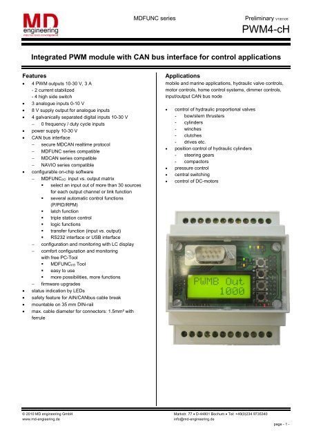
Integrated PWM module with CAN bus interface for control applications<br />
Features<br />
• 4 PWM outputs 10-30 V, 3 A<br />
- 2 current stabilized<br />
- 4 high side switch<br />
• 3 analogue inputs 0-10 V<br />
• 8 V supply output for analogue inputs<br />
• 4 galvanically separated digital inputs 10-30 V<br />
− 0 frequency / duty cycle inputs<br />
• power supply 10-30 V<br />
• CAN bus interface<br />
− secure <strong>MD</strong>CAN realtime protocol<br />
− <strong>MD</strong>FUNC series compatible<br />
− <strong>MD</strong>CAN series compatible<br />
− NAVIO series compatible<br />
• configurable on-chip software<br />
− <strong>MD</strong>FUNCI/O input vs. output matrix<br />
� select an input out of more than 30 sources<br />
for each output channel or link function<br />
� several automatic control functions<br />
(P/PID/RPM)<br />
� latch function<br />
� triple station control<br />
� logic functions<br />
� transfer function (input vs. output)<br />
� RS232 interface or USB interface<br />
− configuration and monitoring with LC display<br />
− comfort configuration and monitoring<br />
with free PC-Tool<br />
� <strong>MD</strong>FUNCI/O Tool<br />
� easy to use<br />
� more possibilities, more functions<br />
− firmware upgrades<br />
• status indication by LEDs<br />
• safety feature for AIN/CANbus cable break<br />
• mountable on 35 mm DIN-rail<br />
• max. cable diameter for connectors: 1.5mm² with<br />
ferrule<br />
Applications<br />
mobile and marine applications, hydraulic valve controls,<br />
motor controls, home control systems, dimmer controls,<br />
input/output CAN bus node<br />
• control of hydraulic proportional valves<br />
- bow/stern thrusters<br />
- cylinders<br />
- winches<br />
- clutches<br />
- drives etc.<br />
• position control of hydraulic cylinders<br />
- steering gears<br />
- compactors<br />
• pressure control<br />
• central switching<br />
• control of DC-motors<br />
© 2010 <strong>MD</strong> <strong>engineering</strong> <strong>GmbH</strong> Markstr. 77 • D-44801 Bochum • Tel: +49(0)234 9735340<br />
www.md-engieering.de info@md-<strong>engineering</strong>.de<br />
page - 1 -
Description<br />
The <strong>MD</strong>FUNC-<strong>PWM4</strong><strong>cH</strong> unit is a pre-programmed and<br />
easy to use I/O module to control proportional functions<br />
with PWM outputs. Up to 4 inductive (e.g. coils) or non<br />
inductive loads can be controlled proportionally. Two of the<br />
outputs are current controlled (up to 3 A) with an<br />
adjustable deviance (less than 5 mA are possible). The<br />
automatic PI-control offers a fast step response.<br />
Additionally a dither signal can be added to avoid sliding<br />
friction.<br />
Three analogue, four digital inputs and a CAN-interface are<br />
available. The <strong>MD</strong>FUNC-<strong>PWM4</strong>H uses the new<br />
<strong>MD</strong>FUNCI/O-engine, which offers more powerful<br />
possibilities for creating your control application. Functions<br />
like multiple station control, network control or positioning<br />
control are pre-programmed and easily accessible. The<br />
onboard LC-display has multiple language support<br />
(English, German, Dutch), offers monitoring functions and<br />
the possibility to change module parameters. For<br />
configuring the module more comfortable, the new PC-Tool<br />
<strong>MD</strong>FUNCI/O is available at the support site. A PC can be<br />
connected via RS232 serial port or via USB (hardware<br />
option).<br />
Furthermore internal data can be displayed on the CANbus<br />
and multiple units can be linked to a network.<br />
Connection diagram<br />
GND<br />
1<br />
AIN Supply<br />
8 V Out<br />
VCC MAIN 12 V/24 V<br />
Analog In<br />
AIN C<br />
GND<br />
AIN B<br />
VCC MAIN 12 V/24 V<br />
LCD<br />
AIN A<br />
GND PWM D<br />
RS 232<br />
or USB<br />
CAN H<br />
PWM D<br />
2 3 4 5 6 7 8 9 10 11 12<br />
CAN<br />
CAN L<br />
PWM<br />
Vin<br />
GND DIN<br />
Run<br />
ESC<br />
OK<br />
UP<br />
DOWN<br />
Digital In<br />
13 14 15 16 17 18 19 20 21 22 23 24<br />
GND PWM C<br />
CAN GND<br />
PWM C<br />
GND PWM B<br />
DIN D<br />
PWM B<br />
DIN C<br />
GND PWM A<br />
DIN B<br />
PWM B<br />
PWM A<br />
PWM A<br />
DIN D DIN C DIN B DIN A<br />
DIN A<br />
<strong>MD</strong>FUNC series Preliminary V<strong>100105</strong><br />
<strong>PWM4</strong>-<strong>cH</strong><br />
Connector description<br />
supply<br />
1,3 GND main system and<br />
analogue input ground<br />
2,4 VCC MAIN main system supply<br />
inputs<br />
analogue inputs<br />
16,15,14 AIN A/B/C analogue inputs<br />
digital inputs<br />
24,23,22,21 DIN A/B/C/D digital inputs<br />
20 GND DIN digital ground<br />
CAN-Bus (I/O)<br />
17,18 CANH,CANL CAN bus connectors<br />
19 CAN GND CAN bus ground<br />
outputs<br />
13 AIN Supply 8V supply for passive<br />
analogue devices: e.g.<br />
joysticks, potentiometers<br />
etc.<br />
12,10 PWM A,B PWM outputs<br />
8,6 PWM C,D PWM outputs<br />
(current controlled)<br />
11,9,7,5 GND PWM<br />
A,B,C,D<br />
PWM ground<br />
Button description<br />
UP/DOWN switch through current menu /<br />
in/decrease a value<br />
OK jump in submenu / select value for<br />
edit / accept edited value<br />
ESC jump out of submenu / cancel value edit<br />
Software assignments<br />
Output A free, calculation channel<br />
Output B free, calculation channel<br />
Output C free, calculation channel<br />
Output D free, calculation channel<br />
Output E free, calculation channel<br />
© 2010 <strong>MD</strong> <strong>engineering</strong> <strong>GmbH</strong> Markstr. 77 • D-44801 Bochum • Tel: +49(0)234 9735340<br />
www.md-engieering.de info@md-<strong>engineering</strong>.de<br />
page - 2 -
Electrical Characteristics<br />
(Tenv = 25° C)<br />
<strong>MD</strong>FUNC series Preliminary V<strong>100105</strong><br />
<strong>PWM4</strong>-<strong>cH</strong><br />
Power supply<br />
Symbol Parameter min typ. max. abs max. Unit<br />
VIn system power supply voltage DC 10 12/24 30 40 V<br />
IIn @ 12 V system current (with LCD) 300 mA<br />
IIn @ 24 V system current (with LCD) 150 mA<br />
Tenv environment temperature -10 25 50 60 °C<br />
PWM A/B/C/D<br />
• high side switches<br />
Symbol Parameter min typ. max. abs max. Unit<br />
Vcc,PWM PWM-stage supply voltage DC 10 12/24 30 40 V<br />
ICC,PWM (both PWM-stage supply current - - 9 13 A<br />
inputs connected)<br />
IPWM A/B/C current per channel 20 - 3000 5000 mA<br />
ton<br />
turn on- switching time 3<br />
- 140 - - µs<br />
turn off- switching time 3<br />
- 70 - - µs<br />
toff<br />
Ron impedance during “on state” - 30 50 - mΩ<br />
fPWM,A/B 1<br />
frequency range channel A and B 1 - 2000 - Hz<br />
fPWM,C 2<br />
frequency range channel C 15 - 1950 - Hz<br />
1 resolution: 1 Hz<br />
2 six frequencies available: 15 Hz, 66 Hz, 122 Hz, 244 Hz, 488 Hz, 1950 Hz<br />
3 10 % VCC,PWM to 90 % VCC,PWM (@VCC,PWM = 13 V)<br />
Digital Inputs A/B/C/D<br />
• inputs galvanically separated<br />
Symbol Parameter min typ. max. abs max. Unit<br />
VDIN,H voltage for high level 3.5 12/24 28 32 V<br />
VDIN,L voltage for low level -0.5 0 2.5 - V<br />
tS,DIN turn on/off time (sample time) - 1 3 - ms<br />
IDIN @ 24 V current per channel 1.0 1 11.0 2 12 - mA<br />
1 @VDIN = 3.5 V<br />
2 optocoupler: 5.5 mA, LED: 5.5 mA<br />
Analog Inputs A/B/C<br />
• averaged values<br />
• overvoltage protected input<br />
Symbol Parameter min typ. max. abs max. Unit<br />
VAIN analog input voltage 0 - 10 11 V<br />
RAIN input impedance 50 4<br />
94 110 - kΩ<br />
fSample internal register update frequency - 400 - - Hz<br />
4 input impedance decreases, when VAIN is higher than 11.2 V<br />
© 2010 <strong>MD</strong> <strong>engineering</strong> <strong>GmbH</strong> Markstr. 77 • D-44801 Bochum • Tel: +49(0)234 9735340<br />
www.md-engieering.de info@md-<strong>engineering</strong>.de<br />
page - 3 -
AIN supply output<br />
• Vsup,AIN = 8 V<br />
• Isup,AIN,max = 90 mA<br />
• output not galvanically separated<br />
CAN bus interface<br />
• galvanically separated<br />
• connectors with CANH and CANL<br />
• max. bus length: 40 m..1000 m<br />
• selectable CAN bus speed: 50, 125, 250, 500, 1000 kBit/s<br />
• blinking RUN-LED and blinking antenna symbol on LCD, when bus OK<br />
• 3 free 16 bit inputs (<strong>MD</strong>CAN protocol)<br />
• 3 free 8 bit inputs (<strong>MD</strong>CAN protocol)<br />
• <strong>MD</strong>CAN protocol output (10 Hz):<br />
- analog inputs A/B/C<br />
- digital inputs (A/B/C/D)<br />
- frequency input (DINA)<br />
- latch status results (A/B/C/D/E)<br />
- output channels (A/B/C/D/E)<br />
RS232 connection<br />
<strong>MD</strong>FUNC series Preliminary V<strong>100105</strong><br />
<strong>PWM4</strong>-<strong>cH</strong><br />
• not galvanically separated<br />
ATTENTION when using PC with grounded outlet power supply GNDPC must have the same potential as GNDPWM3.<br />
If the difference is more than 100 mV you can damage the AOUT2 and your PC. Best use a laptop powered by battery.<br />
• SUB-D 9 pin male connector on board<br />
• connect common zero modem cable to port (also possible with “USB/RS232” adapter)<br />
• data connection: 57600,8,N,1<br />
USB connection<br />
• not galvanically separated<br />
ATTENTION when using PC with grounded outlet power supply GNDPC must have the same potential as GNDPWM3.<br />
If the difference is more than 100 mV you can damage the AOUT2 and your PC. Best use a laptop powered by battery.<br />
• Mini-USB connector 5 pin on board<br />
• USB 1.1 standard<br />
• connect AOUT2 with common Mini-USB cable to your PC<br />
• on board USB/RS232 adapter, device will appear as COM-port on your PC<br />
• RS232 data connection: 57600,8,N,1<br />
• driver for free download<br />
© 2010 <strong>MD</strong> <strong>engineering</strong> <strong>GmbH</strong> Markstr. 77 • D-44801 Bochum • Tel: +49(0)234 9735340<br />
www.md-engieering.de info@md-<strong>engineering</strong>.de<br />
page - 4 -
Setup Program: <strong>MD</strong>FUNC-I/O Tool Version 2.3<br />
<strong>MD</strong>FUNC series Preliminary V<strong>100105</strong><br />
<strong>PWM4</strong>-<strong>cH</strong><br />
• more possibilities, better overview<br />
• easy user interface<br />
• free input-output combinations<br />
• inputs from local analogue inputs, digital inputs, CAN bus inputs or system outputs for feedback<br />
• Boolean operations, latch function<br />
• CAN bus inputs/outputs<br />
• Input vs. Output transfer function<br />
• Ramp functions with gain and offset limitation<br />
• monitor functions<br />
• load/save settings from/to file<br />
• special functions: automatic control, multiple station control<br />
• Requirements:<br />
• Win2000/XP<br />
• CPU with 600 MHz or higher<br />
• COM port or USB port<br />
© 2010 <strong>MD</strong> <strong>engineering</strong> <strong>GmbH</strong> Markstr. 77 • D-44801 Bochum • Tel: +49(0)234 9735340<br />
www.md-engieering.de info@md-<strong>engineering</strong>.de<br />
page - 5 -
Package dimensions (in mm)<br />
Order codes<br />
<strong>PWM4</strong><strong>cH</strong> with RS232 connector<br />
<strong>MD</strong>FUNC-<strong>PWM4</strong><strong>cH</strong>-RS232-LCD<br />
<strong>PWM4</strong><strong>cH</strong> with USB-connector<br />
<strong>MD</strong>FUNC-<strong>PWM4</strong><strong>cH</strong> -USB-LCD<br />
RS232-PC connection cable<br />
<strong>MD</strong>CABLE-RS232-ZERO<br />
USB-PC connection cable<br />
<strong>MD</strong>CABLE-MiniUSB<br />
<strong>MD</strong>FUNC series Preliminary V<strong>100105</strong><br />
<strong>PWM4</strong>-<strong>cH</strong><br />
Please ask for special device programming, other CAN protocol stacks or our “low cost solutions” (e.g. not galvanically separated or no LCD).<br />
Support<br />
Get datasheets, drivers, firmware, software and examples from:<br />
www.md-<strong>engineering</strong>.de<br />
© 2010 <strong>MD</strong> <strong>engineering</strong> <strong>GmbH</strong> Markstr. 77 • D-44801 Bochum • Tel: +49(0)234 9735340<br />
www.md-engieering.de info@md-<strong>engineering</strong>.de<br />
page - 6 -
