future - Schulze Elektronik GmbH
future - Schulze Elektronik GmbH
future - Schulze Elektronik GmbH

You also want an ePaper? Increase the reach of your titles
YUMPU automatically turns print PDFs into web optimized ePapers that Google loves.
operating instructions v30 and higher date of issue: 12 JUN 2002<br />
<strong>future</strong> with shpa (super high performance algorithm)<br />
speed controller for brushless and sensorless motors<br />
6<br />
5<br />
4<br />
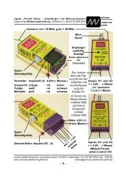
Key to illustration:<br />
1 Receiver cable, 3-pin:<br />
- = negative . . . . . . . . black or brown<br />
+ = positive . . . . . . . . red<br />
p = pulse . . . . . . . . . white or orange<br />
2 Battery connection neg (-) . black<br />
3 Battery connectin pos. (+) . red Reverse use:<br />
4 Motor connection a . . . . . red . . . . . . . . . . . blue, black<br />
5 Motor connection b . . . . . white, yellow . . . . . . white, yellow<br />
6 Motor connection c . . . . . blue, black . . . . . . . red<br />
- 1 -<br />
schulze<br />
elektronik<br />
gmbh<br />
Please note the following guidelines, which apply when you are connecting the<br />
motor and reversing its direction of rotation:<br />
1) The controller can be used with sensorless and sensor-controlled motors. If your motor<br />
is sensor-controlled, the 5-pin connector is not used.<br />
2) The three motor cables can be connected in any order.<br />
3) To reverse the direction of rotation you have to swap over two of the three motor<br />
cables; we recommend that you swap the two outer wires.<br />
Unfortunately the colour coding of the motor windings may not apply consistently to the<br />
sensor-controlled and sensorless types.<br />
Note: for right-hand rotation, Plettenberg motors should be connected as the colour code shows.<br />
Mostly <strong>future</strong>s should be connected with the cooling plate facing the outside of the fuselage.<br />
schulze elektronik gmbh • prenzlauer weg 6 D-64331 weiterstadt fon: 06150/1306-5, fax: 1306-99<br />
internet: http://www.schulze-elektronik.com e-mail: mail@schulze-elektronik.com<br />
2<br />
3<br />
1
Dear customer,<br />
Congratulations on your choice of a <strong>future</strong> speed controller, which is a micro-computer controlled<br />
unit developed and manufactured entirely in Germany, designed for brushless and sensorless<br />
3-phase rotary current motors.<br />
All models of the <strong>future</strong> are amongst the world’s smallest, lightest and most capable speed controllers.<br />
<strong>future</strong> controllers have the most intelligent, comprehensive software, which means that this<br />
speed controller (or governor) is capable of operating virtually any brushless motor currently on<br />
the market with optimum efficiency.<br />
The ips (intelligent programming system) which is a standard feature of the -bo/ -Ko/ -be versions<br />
of the <strong>future</strong>, makes it as simple as possible to configure the controller to match any radio<br />
control system.<br />
The transmitter stick travel settings of the special types (<strong>future</strong> -H) are pre-set and fixed.<br />
The integral motor connector system is a feature of all <strong>future</strong> controllers up from 35A nominal<br />
current, and makes it possible to remove the unit for servicing, or for fitting in another model,<br />
simply by unplugging the cables - no soldering is required.<br />
This operating instruction is only valid for types from software version 30 and higher (non volatile<br />
setting of motor mode and operating mode).<br />
Contents<br />
Chapter Subject Page<br />
1 Warning notes, cautions . . . . . . . . . . . . . . . . . . . . . 3<br />
2 Ensuring safe, trouble free operation . . . . . . . . . . . . . . 4<br />
3 Intended applications and common highlights . . . . . . . . . 5<br />
4 Protective circuits . . . . . . . . . . . . . . . . . . . . . . . . . 6<br />
5 Monitor displays . . . . . . . . . . . . . . . . . . . . . . . . . . 7<br />
6 Installing and connecting the unit . . . . . . . . . . . . . . . . 7<br />
7 Connector systems and mounting instructions, servos . . . . 8<br />
8 Using the controller for the first time . . . . . . . . . . . . . . 10-19<br />
8.1 ips - the intelligent programming system ips 30 . . . . . . . . . 10<br />
8.2 Symbols and terminology . . . . . . . . . . . . . . . . . . . . . 11<br />
8.3 Notes on changing motor timing and switching frequency . . . . 11<br />
8.4.1 <strong>future</strong>-bo/ -Ko/ -be . . . . . . . . . . . . . . . . . . . . . . . . . 12<br />
8.4.1.1 Configurating of the Operating Mode (<strong>future</strong>-bo/ -Ko/ -be) . . . . . 13<br />
8.4.1.2 Available Motor Modes of the <strong>future</strong>-bo/ -Ko/ -be . . . . . . . . . 14<br />
8.4.1.3 Configuration of the Motor Mode (<strong>future</strong>-bo/ -Ko/ -be). . . . . . . . 15<br />
8.4.2 <strong>future</strong>-He/ -Ho. . . . . . . . . . . . . . . . . . . . . . . . . . . . 16<br />
8.4.2.1 Configurating of the Operating Mode (<strong>future</strong>-Ho/ -He) . . . . . . . 17<br />
8.4.2.2 Available Motor Modes of the <strong>future</strong>-Ho/ -He . . . . . . . . . . . 18<br />
8.4.2.3 Configuration of the Motor Mode (<strong>future</strong>-Ho/ -He) . . . . . . . . . 19<br />
9 Tips . . . . . . . . . . . . . . . . . . . . . . . . . . . . . . . . . 20<br />
10 Legal matters . . . . . . . . . . . . . . . . . . . . . . . . . . . 23<br />
11 Specifications . . . . . . . . . . . . . . . . . . . . . . . . . . 24<br />
12 Product overview . . . . . . . . . . . . . . . . . . . . . . . . . 25<br />
- 2 -
1 Warning notes, cautions<br />
Electric motors fitted with propellers are dangerous<br />
and require proper care for safe operation.<br />
Keep well clear of the propeller at all<br />
times when the battery pack is connected.<br />
Technical defects of an electrical or mechanical<br />
nature may result in unintended motor<br />
runs; loose parts may cause serious personal<br />
injuriy and/or property damage.<br />
The CE-certificate on the speed controller<br />
does not absolve you from taking proper care<br />
when handling the system!<br />
Speed controllers are exclusively for use in<br />
RC models. Their use in man-carrying aircraft<br />
is prohibited.<br />
Speed controllers are not protected against<br />
reverse polarity (+ terminal and - terminal reversed).<br />
Connecting the battery pack to the<br />
motor leads of the controller will almost certainly<br />
cause irreparable damage.<br />
Electronic equipment is sensitive to humidity.<br />
Speed controllers which have got wet may<br />
not function properly even after thorough drying.<br />
You should send them back to us for<br />
cleaning and testing.<br />
Do not use speed controllers in conjunction<br />
with a power supply connected to the mains.<br />
Energy reversal can occur when the motor<br />
slows down and stops, and this may damage<br />
the power supply or cause an over-voltage<br />
condition which could damage the controller.<br />
Never disconnect the flight pack while the<br />
motor is running, as this could cause damage<br />
on a speed controller.<br />
Please take care when switching off the receiver<br />
battery: depending on the receiver you<br />
are using, it may send an incorrect throttle<br />
signal to the <strong>future</strong> at this moment, which<br />
could then cause the motor to burst into life<br />
unexpectedly.<br />
If you are using a <strong>future</strong> with BEC system:<br />
a) On no account connect a separate receiver<br />
battery or an electronic battery switch (two<br />
receiver batteries), as this may cause damage<br />
to the speed controller and could cause<br />
current to flow from the receiver battery to<br />
the motor.<br />
- 3 -<br />
b) If you want to use a separate receiver battery<br />
cut through the + wire in the receiver cable,<br />
or pull it out of the connector if possible.<br />
However, for greater protection against motor-inducted<br />
interference it is always better to<br />
use a speed controller with an opto-coupler.<br />
Protect the speed controller from mechanical<br />
loads, vibration, dirt and contamination.<br />
Keep the cables to the motor as short as<br />
possible (max. length = 10 cm / 4”).<br />
Do not exceed the maximum stated length of<br />
cable between battery and <strong>future</strong> (max.<br />
length: 20 cm / 7...8"). The wiring inside the<br />
battery pack must also be as short as possible.<br />
Use in-line soldered “stick” packs.<br />
For the same reason, use a clamp-type amperemeter,<br />
not a series meter with shunt resistor.<br />
Never leave the flight battery connected<br />
when ...<br />
... the model is not in use and/or<br />
... the battery pack is being charged.<br />
Although some speed controllers feature a<br />
separate On/Off switch, this does not isolate<br />
it completely from the battery.<br />
Speed controllers can only function properly<br />
if they are in full working condition. The protective<br />
and monitoring circuits can also only<br />
work if the speed controller is in good operating<br />
condition.<br />
In the case of motor failure (e.g.short circuits<br />
in the windings) the over-temperature sensor<br />
in the controllers may react too slowly to prevent<br />
damage. Switch the motor off immediately<br />
to prevent permanent damage to the<br />
speed controller.<br />
Note: Please remember that the monitoring<br />
circuits are unable to detect every abnormal<br />
operating condition, such as a short between<br />
the motor cables. Note also that a stalled motor<br />
will only trip the current limiter if the motor's<br />
stall current is well above the controller's<br />
peak current. For example, if you are using<br />
an 80 A controller in conjunction with a 20<br />
A motor, the current monitor will not detect an<br />
excessive current even when the motor is<br />
stalled.
2 Ensuring safe, trouble-free operation<br />
Use only compatible connectors. A 2 mm pin<br />
cannot provide reliable contact in a 2.5 mm<br />
socket. The same applies with 2mm goldcontact<br />
pins and 2 mm tin-plated sockets.<br />
Please also remember that ...<br />
... the wiring of your RC-components must be<br />
checked regularly for loose wires, oxidation,<br />
or damaged insulation, especially when using<br />
a BEC system.<br />
... your receiver and the aerial must be at<br />
least 3 cm (>1") away from motor, speed<br />
controller and high-current cables. For example,<br />
the magnetic fields around the high-current<br />
cables can cause interference to the receiver.<br />
... all high-current cables must be as short as<br />
possible. Maximum length between flight<br />
pack and speed controller should not exceed<br />
20 cm (7"), between speed controller and<br />
motor: 10 cm (4").<br />
... all high-current cables longer than 5 cm<br />
(2") must be twisted together. This applies in<br />
particular to the motor power cables, which<br />
are very powerful sources of radiated interference.<br />
... in model aircraft: half of the receiver aerial's<br />
length should be routed along the fuselage,<br />
the other half should be allowed to trail<br />
freely (take care not to tread on it). Do not attach<br />
the end of the aerial to the fin!<br />
... in model boats: half of the receiver aerial's<br />
length should be deployed inside the hull<br />
above the waterline, the other half should be<br />
threaded into a small tube mounted upright.<br />
Every time you intend to use the power<br />
system - before you turn on the receiver -<br />
make sure that ...<br />
... no one else is using the same frequency<br />
(identical channel number).<br />
... your transmitter is switched on and the<br />
throttle stick is (as a rule) in the STOP position<br />
(exceptions see Section 9).<br />
Carry out a range check before each flight.<br />
Ask an assistand to hold the model aircraft<br />
and set the throttle stick to the half throttle<br />
position. Collapse the transmitter aerial.<br />
Walk away from the model to the distance<br />
- 4 -<br />
stated by the RC system manufacturer (this<br />
might be a distance of about 50-60 m = 200').<br />
Make sure that you still have full control of<br />
the system at this range.<br />
As a general rule: receiver interference is<br />
more likely to occur when using a controller<br />
with BEC system, as these units do not feature<br />
an opto-coupler with its optical link.<br />
When Ni-Cd batteries approach the end of<br />
their charge, voltage falls drastically and<br />
quickly. The <strong>future</strong> detects this and reduces<br />
power to the motor automatically. This should<br />
leave sufficient energy to bring your model<br />
safely back home. However, if you use a<br />
small number of cells of high internal resistance<br />
and operate at high motor currents, the<br />
controller may reduce power before the pack<br />
is discharged. You can eliminate this problem<br />
by using low resistance straps to connect the<br />
cells, or use the direct cell-to-cell soldering<br />
technique (“sticks”) and short, heavy-gauge<br />
wire if you assemble your own batteries.<br />
Your receiver also benefits from the stability<br />
of the voltage supplied from the battery by a<br />
BEC system. If the BEC voltage is stable, the<br />
receiver is less liable to suffer interference.<br />
The CE symbol is your guarantee that the<br />
unit meets all the relevant interference emission<br />
and rejection regulations when it is in<br />
use.<br />
If you encounter problems operating the <strong>future</strong><br />
controller, please note that many problems<br />
are due to an unsuitable combination of<br />
receiving system components, or an inadequate<br />
installation in the model.
3 Intended applications<br />
Highlights common to all units:<br />
Better than 250-step resolution over the<br />
whole control range for extremely fine<br />
speed control.<br />
“Auto-arm” function and “power on reset”<br />
“ips 30” (intelligent programming system)<br />
with no pots! The speed controller automatically<br />
configures itself every time to the stick<br />
travel when you switch your receiver on respectively<br />
you connect your battery pack.<br />
The brake can also be disabled in the same<br />
way if required.<br />
“ips” also includes a special setup variant for<br />
geared motor systems. Fixed stick travel between<br />
braking point and full-throttle point,<br />
softstart for throttle and brake. It is normally<br />
essential to apply full-throttle at the start of<br />
the flight. This variant only learns one stick<br />
position (brake point) when in use. Fine-tuning<br />
the system to match the transmitter’s stick<br />
travel is still possible, but must be done by<br />
adjusting the travel at the transmitter.<br />
During the configuration process the motor<br />
acts as a loudspeaker to give you audible<br />
confirmation of the procedure.<br />
All <strong>future</strong> types with shpa include a timing<br />
and/or pulse frequency adjustment facility,<br />
which enables you to make adjustments<br />
without additional cables or push-buttons.<br />
This feature allows us to cater more accurately<br />
for the different magnetic field geometries<br />
and flux concepts employed by the<br />
various motor manufacturers. This function<br />
also lets you offset the maximum efficiency<br />
point to suit your particular application.<br />
Use with Tango/Samba motors: set the<br />
pulse frequency of your <strong>future</strong> to 38 kHz.<br />
You may find that your power system operates<br />
at higher efficiency set to 19 kHz,<br />
but this is below the pulse frequency<br />
which the manufacturer approves for<br />
these motors (to avoid invalidating the<br />
warranty).<br />
- 5 -<br />
Niedervolt-Typen:<br />
<strong>future</strong>-45bo: This controller is primarily<br />
designed for use in electric gliders or all<br />
purposes with non excessive half throtle<br />
use. 6 to 17 Ni-Cd / Ni-MH cells.<br />
<strong>future</strong>-45be: Identical to the <strong>future</strong>-45bo,<br />
but with the addition of a BEC system.<br />
That’s why can be used with 6 - 12 cells.<br />
<strong>future</strong>-45Ko: The controller for longer durating<br />
half throttle as used in sport models,<br />
aerobatic models or ducted fan models.<br />
Batt. range 6 - 17 cells; finned heatsink.<br />
<strong>future</strong>-45He/Ho: Steller für Hubschrauber<br />
mit langdauerndem Start-Sanftlauf. Regler-<br />
oder Stellerbetrieb möglich. 6-10 Ni-<br />
Cd/Ni-MH Zellen in der ...He Version, bei<br />
...Ho bis 17 Zellen; Rippenkühlkörper; feste<br />
Knüppelpositionen für Leerlauf und<br />
Vollgas.<br />
<strong>future</strong>-58bo: This version can be used<br />
with 7 to 17 Ni-Cd cells in any model<br />
where the capacity of the 45A version is<br />
marginal, and where the 90A type would<br />
represent a sledgehammer to crack a nut.<br />
With its improved efficiency it is also a<br />
good choice in models where cooling can<br />
be problematic. The intended applications<br />
therefore include small hotliners and small<br />
ducted-fan models.<br />
High voltage types:<br />
<strong>future</strong>-35bo: The controller for high cell<br />
numbers, for example as used in ductedfan<br />
models. Battery range 16 - 30 cells;<br />
finned heat-sink.<br />
<strong>future</strong>-35Ho: Controller for helicopters<br />
with long durating initial softstart. 16-30<br />
Ni-Cd / Ni-MH cells; cooling rips; fixed<br />
stick positions for neutral and full throttle.<br />
Normal speed controller and constant rpm<br />
use. Autorotation use.<br />
<strong>future</strong>-55bo: The high-current controller<br />
for high cell count. Batt. range 16...30<br />
cells; finned heat-sink.
4 Protective circuits<br />
Note: the monitor circuits are effective, but<br />
they cannot detect every possible operating<br />
condition.<br />
Temperature monitor:<br />
The temperature monitor switches off the motor.<br />
You can reset the unit using the "autoarm"<br />
function (throttle stick to stop for about<br />
2 sec.) If the motor windings are shortcircuited<br />
the temperature monitor<br />
reacts too slowly to prevent damage.<br />
Switch the motor off immediately<br />
to avoid permanent damage<br />
to the speed controller.<br />
Voltage monitor:<br />
As soon as the voltage of the drive battery<br />
falls back to the 5V threshold the motor is<br />
throttled back.<br />
If the situation which caused the controller to<br />
throttle back continues for more than a short<br />
time, the unit switches the motor off.<br />
Of course, you can re-start the motor again<br />
briefly by moving the throttle stick back to<br />
"stop" for about 2 seconds to re-arm the system.<br />
If you use a <strong>future</strong> with opto-coupler you retain<br />
full control of the model until the receiver<br />
battery is flat;<br />
if you use a <strong>future</strong> with BEC system the<br />
power system and the model remain fully<br />
controllable until the last usable energy in the<br />
flight pack is exhausted. We can not predict<br />
how long you can still control your model with<br />
the residual battery charge as this depends<br />
on many parameters such as the number of<br />
cells in the pack, the cell type, actual motor<br />
current and the way you control your model.<br />
The only solution is for you to time the period<br />
yourself with the model on the ground. If the<br />
voltage monitor trips, i.e. the motor starts to<br />
throttle back without your intervention, you<br />
should stop the motor at once with the throttle<br />
stick in any case so that you have the<br />
maximum possible reserve of power.<br />
Current monitor:<br />
Our <strong>future</strong> controllers feature a current monitor<br />
circuit which trips when the current rises<br />
above the specified maximum value. If the<br />
motor is stalled, the motor is throttled back.<br />
- 6 -<br />
This means, that a motor which draws an excessive<br />
current will never reach full-throttle,<br />
and the current may stay below the specified<br />
maximum value. If <strong>future</strong> is some seconds in<br />
current limiting mode, it will disarm itself<br />
(switching off the motor).<br />
Maximum speed monitor:<br />
If maximum rotational speed of the motor will<br />
exceed, <strong>future</strong> throttles down. In this state<br />
do not use longer then 1 second.<br />
<strong>future</strong> bo or ko types cut off instantly.<br />
Because of this: Do not run motor without<br />
airscrew.<br />
Minimum speed monitor:<br />
To ensure that the controller detects the rotor<br />
position reliably, this series of <strong>future</strong> types<br />
sets a defined minimum rotational speed. If<br />
the rotor speed falls below this value continuously,<br />
the controller switches the motor off.<br />
You can over-ride the reset with the “autoarm”<br />
function (throttle stick to stop for about<br />
2 sec). This protective function can cause the<br />
motor to be reluctant to start up if its torque<br />
limit is exceeded. If you are using one of the<br />
...bo types with V03 software the only time<br />
you may notice this is when you first start the<br />
motor after changing the battery. In this case<br />
a propeller one step smaller in diameter must<br />
be used. If this should happen, check that the<br />
maximum permissible motor current is not exceeded.<br />
Receiver signal monitor:<br />
If the receiver signal fails, or the signal is<br />
longer or shorter than the usual range of values,<br />
the smart controller reverts to hold mode<br />
for about 300 milliseconds before switching<br />
to disarmed mode.<br />
This warning function enables you to eliminate<br />
receiver interference before you actually<br />
lose your model, perhaps by modifying the<br />
installation or changing the radio control<br />
components<br />
Reverse polarity protection:<br />
These speed controllers are not<br />
protected against reversed polarity!<br />
Watchdog:<br />
If this circuit is tripped the speed controller<br />
stops working briefly and then reverts to normal<br />
operation.
5 Monitor displays<br />
The <strong>future</strong> is fitted with LEDs to indicate its<br />
operating status „disarmed“, „neutral“ or<br />
„brake enabled“.<br />
However, when the unit is being configured<br />
the set stick end-points are (in dependence<br />
6 Installation, connections<br />
Installing in the fuselage:<br />
Velcro (hoop and loop) tape is the ideal<br />
method of mounting the controller in the fuselage.<br />
Do not pack the <strong>future</strong> in foam as this<br />
may lead to a heat buildt-up in the controller.<br />
Receiver connection:<br />
Connect the receiver cable attached to the<br />
<strong>future</strong> to the receiver servo output corresponding<br />
to the throttle stick on the transmitter<br />
(or a switch if that is your preference).<br />
The <strong>future</strong> receives its control signal via this<br />
receiver socket.<br />
If you use a <strong>future</strong> with BEC system and one<br />
receiver cable, power is supplied to the receiver<br />
via the same cable. If the <strong>future</strong> has<br />
two receiver cables, please connect the twocore<br />
cable to the receiver socket to which the<br />
receiver battery would normally be connected,<br />
or to any other vacant receiver socket.<br />
Check regularly especially in this case that<br />
the receiver cable is undamaged and firmly<br />
seated at the <strong>future</strong>.<br />
On no account connect a separate receiver<br />
battery or an electronic battery switch (two<br />
receiver batteries), as this may cause damage<br />
to the speed controller.<br />
Length of connecting cables:<br />
Power-connection battery <strong>future</strong>:<br />
Do not exceed the maximum stated length of<br />
cable between battery and <strong>future</strong><br />
(max. length: 20 cm / 7...8”), otherwise<br />
the speed controller may<br />
be damaged. This rule still applies<br />
even if your power system features a retractable<br />
(folding) motor, or your model necessarily<br />
includes a long battery cable!!! Battery<br />
packs which are assembled in a zig-zag pattern<br />
also produce ”long cable” effects; use in-<br />
- 7 -<br />
of the used <strong>future</strong>-type or ips-mode) confirmed<br />
by a beep from the motor or a barely<br />
reciptible "blip" in full-throttle position when<br />
normal using with activated brake.<br />
line soldered packs exclusively. It is essential<br />
to use polarized gold-plated-contact connectors<br />
- fitting any other type of connector invalidates<br />
the warranty.<br />
Connectors which do not have a polarised<br />
insulator can be made safe (i.e. polarised) by<br />
soldering the <strong>future</strong>’s positive battery wire to<br />
a socket, and the <strong>future</strong>’s negative wire to a<br />
plug.<br />
We recommend that you choose your connectors<br />
from our selection in Section 8 - fitting<br />
any other type of connector invalidates<br />
the warranty.<br />
Power-connection <strong>future</strong> motor:<br />
The cables to the motor should be kept as<br />
short as possible to avoid interferences to<br />
your reiceiver. Long cables tend to act as<br />
aerials and radiate interference; they also<br />
add unnecessary weight (see also section 2).<br />
Cut down the existing motor cables to a<br />
length of no more than 10 cm. Do not extend<br />
the motor cables except in exceptional cases;<br />
although this generally does not harm to the<br />
<strong>future</strong> itself.<br />
Locate the cables with the pp35 plugs supplied<br />
with the controller (plugged into the <strong>future</strong>),<br />
and solder them to the motor cables.<br />
See separate sheet (page 1) for details of cable<br />
configuration.<br />
Avoid pulling on the motor cables; we recommend<br />
that you secure the three motor plugs<br />
with glass-reinforced tape to prevent them<br />
being pulled out.
7 Connector systems and mounting instructions<br />
7.1 3.5 mm gold-contact connector system (pp35); max. load > 80A<br />
+ red plug wide sleeve narrow socket + red ( akku)<br />
battery <strong>future</strong><br />
- black socket narrow sleeve wide plug - black ( akku)<br />
Caution: remove locating lug from battery cable. Do not remove lug from any cables<br />
attached to controllers or charge leads!<br />
Manufacturer’s information: the pp35 plug is very short, and this presents the<br />
danger that the spring contact could lose its resilience due to excessive heat<br />
build-up during the soldering process. You can side-step the problem by keeping<br />
the temperature below 200°C as follows: either remove the contact carefully<br />
before soldering, or simply push the plug into a piece of wet fine-grain sponge<br />
for soldering, or plug it in a 3.5 mm hole of a copper-block.<br />
Fit the connectors in the order shown above; the contacts are pressed in as follows:<br />
a. Place plastic sleeve vertically on table, grip end up.<br />
b. Push contact down into sleeve.<br />
c. Place 2.5 mm wide screwdriver blade on top of cable solder joint inside sleeve.<br />
d. Tap screwdriver to press contact into sleeve until latch engages.<br />
7.2 4 mm gold-contact connector system (CT 4, also CT 2); max. load > 80A<br />
+ red sleeve wide plug socket sleeve narrow red ( akku)<br />
battery <strong>future</strong><br />
- black sleeve narrow socket plug sleeve wide black ( akku)<br />
Fit the connectors in the order shown above; the contacts are pressed in as follows:<br />
a. Rest plastic sleeve on vice jaws with cables hanging down.<br />
b. Close vice jaws until cables are just free to move.<br />
c. Fit plug into socket and tap into sleeve until latch engages.<br />
d. Fit socket onto plug and tap into sleeve until latch engages.<br />
- 8 -
7.3 MPX gold-contact connector system (green or red); max. load ~30A<br />
+ red heat-shrink socket plug heat-shrink + red ( akku)<br />
battery <strong>future</strong><br />
- black heat-shrink socket plug heat-shrink -black ( akku)<br />
Fit the connectors in the order shown above; the contacts are soldered as follows:<br />
a. To center the contacts fit plug and socket together before soldering.<br />
b. Tin all 6 exposed contacts of plug or socket.<br />
c. Fit cable end into triangle of contacts, solder to all three contacts.<br />
d. Position heat-shrink sleeve and shrink over joint.<br />
7.4 2.0 / 2.5 mm gold-contact connector system; max. load ~30A<br />
+ red socket sleeve narrow sleeve wide plug + red ( akku)<br />
+ Code +<br />
battery <strong>future</strong><br />
- black socket sleeve narrow sleeve wide plug -black ( akku)<br />
Fit the connectors in the order shown above; the contacts are pressed in as follows:<br />
a. Place plastic sleeve vertically on table, grip end up.<br />
b. Push contact down into sleeve.<br />
c. Place 2.5mm wide screwdriver blade on top of cable solder joint inside sleeve.<br />
d. Tap screwdriver to press contact into sleeve until latch engages.<br />
7.5 Suitable servos for BEC operation (selection)<br />
DYMOND D 60<br />
FUTABA 5102<br />
GRAUPNER C261, C341, C351, C3041, C3321<br />
MEGATECH MTC FX200<br />
ROBBE FS40 #8433<br />
VOLZ Microstar, Wingstar, Zip<br />
- 9 -
8 Initial use<br />
8.1 ips, the intelligent programming system<br />
for configuring the <strong>future</strong> to suit your application<br />
In general terms: in its standard form (mode 1 = default mode) the <strong>future</strong> works with all<br />
motors known to us, i.e. without you having to make any adjustments to it!<br />
If you have a transmitter with adjustable servo travel we recommend that you set throttle-servo<br />
to normal full travel, i.e. +/- 100%. Adjust Multiplex servo center pulse width to 1.5 ms<br />
(= -22% center or use UNI-Mode).<br />
The ips30 consists of three components:<br />
a) Configuring the controller’s Operating Mode (i.e. the application) and<br />
b) configuring the controller’s Motor Mode (i.e. the motor to be used) and<br />
c) matching the controller automatically to the transmitter’s stick travel.<br />
Points a) and b) are explained in the following pages. Point c) includes two different procedures,<br />
one of which (c1) is also explained on the following pages:<br />
The procedure for matching the controller to the stick travel is basically the same as before,<br />
when using the controller for the first time, and is fully automatic in operation:<br />
c1) For normal applications use the standard procedure: 1. Transmitter to Stop, 2. Switch on<br />
receiver, 3. Connect flight pack / drive battery (<strong>future</strong> confirms “motor mode” with 1…6<br />
beeps, waits 2 seconds, confirms “operating mode” with 1…4 two-tone beeps, then learns<br />
the Stop position, confirms this with a single beep and arms itself), 4. Hold model in launch /<br />
start position, 5. Apply full-throttle (<strong>future</strong> learns full-throttle point, confirms with brief drop<br />
in motor speed), 6. Launch / start model.<br />
This process configures both the brake point and the full-throttle point, so that full stick<br />
travel is always available, giving fine control of motor speed.<br />
c2) If the brief drop in motor speed at full-throttle (confirming the learned full-throttle position) is<br />
disturbing or annoying, or if you don’t wish to apply full-throttle at launch, use this alternative<br />
procedure: set the throttle stick to full-throttle before you switch on the receiving system<br />
and connect the flight pack / drive battery. The <strong>future</strong> beeps for motor mode, emits two-tone<br />
beeps for operating mode, then confirms “full throttle position learned” with a double beep.<br />
Now move the transmitter stick to Stop, and the <strong>future</strong> emits a single beep (i.e. brake<br />
position learned, <strong>future</strong> armed). You can now start or launch the model using any throttle<br />
position.<br />
The helicopter programs do not provide a means for the user to configure the stick travels, i.e. both<br />
the idle and full-throttle positions are fixed.<br />
If you want to exploit full transmitter stick travel to vary the rotational speed of your helicopter, we<br />
recommend that you reduce the servo travel slightly at the transmitter. Caution: reducing it too<br />
far will prevent you obtaining full throttle and/or the Stop position (controller will not be armed).<br />
If your <strong>future</strong> beeps twice (double beep = full throttle position) when the transmitter stick is at<br />
the brake position, you must reverse the throttle channel using your transmitter’s servo reverse<br />
function. If you neglect to do this, the <strong>future</strong> will be armed (single beep) at the transmitter’s<br />
full-throttle setting, and run at full-throttle at the stop setting, which is not recommended!<br />
The next pages includes instructions on operating your speed controller. There you will discover<br />
that the <strong>future</strong> emits a certain number of beeps when you connect the power battery; the<br />
number of beeps varies according to the set modes. This is how the <strong>future</strong> tells you the<br />
part-load switching frequency and timing and the Operating Mode which are currently set on<br />
your particular controller. The range of adjustment facilities varies according to controller<br />
type (wing aircraft or helicopter), and they are described in full in the section covering the<br />
use of the controller.<br />
Once the <strong>future</strong> is configured, the “Operating Modes” and the “Motor Modes” are stored in the<br />
unit until you change them again, i.e. they are not lost when you disconnect the battery.<br />
- 10 -
8.2 Symbols and terminology<br />
Stick: The throttle stick on the transmitter<br />
Neutral position (self neutralising stick)<br />
Idle position (position where the motor just barely runs) or stop position (brake).<br />
Brake position or idle position<br />
Position of the throttle stick where the motor stops or just barely runs.<br />
Full-throttle position<br />
100% voltage passed to the motor.<br />
Wait (0.5 seconds)<br />
Audible indicators:<br />
These indicators are only audible when a motor is attached, as the motor<br />
itself acts as the loudspeaker.<br />
Single beep<br />
Double beep<br />
Duotone<br />
Momentary interruption in running (inverse beep)<br />
- 11 -<br />
�<br />
�������<br />
8.3 Notes on changing motor timing and switching frequency<br />
��<br />
The general rule is: the harder the timing, the higher the current at which maximum<br />
efficiency occurs. However, optimum timing also varies according to the design<br />
of the motor. For this reason we state recommended timings for each motor<br />
type. Within certain limits, it is also possible to adjust the motor to suit a particular<br />
aircraft propeller or boat propeller by modifying the timing.<br />
When selecting the switching frequency the general rule is this: the lower the motor’s<br />
inductivity, the higher the switching frequency should be. Increasing the<br />
switching frequency reduces non-linearity in the current flow in part-load mode,<br />
but at the same time causes a rise in eddy current losses in the motor and<br />
switching losses in the controller. The simplest method is to try out different<br />
switching frequencies, and select the one at which the motor and the <strong>future</strong><br />
heat up the least.<br />
Mode 1 is the standard mode. As a rule <strong>future</strong> is shipped in this mode.<br />
���
8.4.1 Operating the <strong>future</strong> -bo/ -Ko/ -be from v30<br />
a Receiver off (flight battery disconnected)<br />
b Set throttle stick to brake position<br />
c Switch transmitter on<br />
d Switch receiver on (connect flight battery)<br />
e <strong>future</strong> shows Motor Mode with single tone beep(s)<br />
f waits 2 seconds<br />
g <strong>future</strong> shows Operating Mode with duotone beep(s)<br />
h waits 2 seconds, learns and confirms brake position with<br />
a single tone beep and is now armed!<br />
i Hold model in launch position, keep clear of danger area<br />
around propeller!<br />
j Move throttle quickly to full-throttle position and ...<br />
... leave it there for about 1/2 second. Motor is already running<br />
- as with a conventional speed controller<br />
k <strong>future</strong> confirms full-throttle position by interrupting the motor<br />
run very briefly - a barely perceptible "blip"<br />
l The <strong>future</strong> is completely configured and the model can be<br />
flown<br />
- 12 -<br />
TXon<br />
RXon<br />
�(�.. �)<br />
��(��.. ��)<br />
Also see „Configuration of the Operating Mode“ in chapter 8.4.1.1<br />
and of the „Motor Mode“ chapter 8.4.1.2 resp. 8.4.1.3<br />
�<br />
���
8.4.1.1 Configuration of the Operating Mode<br />
<strong>future</strong> -bo/-be/-Ko, from v30<br />
a Switch transmitter on<br />
b Switch receiver on (<strong>future</strong> with opto coupler)<br />
c Set transmitter stick to full throttle position (> 1,67 ms)<br />
d Connect Drive-/Flight battery<br />
e <strong>future</strong> confirms with Motor Mode-,<br />
old Operating Mode- and „full throttle learned-“beep(s)<br />
f Wait for duotone beep (10 s)<br />
g Move throttle stick to stop position (< 1,40 ms) within 1.5 seconds<br />
h Wait for duotone beep (1.5 s)<br />
i Move throttle stick to half throttle position (1,41 ... 1,67 ms) within 1.5 seconds<br />
j Wait for duotone beeps<br />
This beep means: ”Caution, count signals” (i.e. with your fingers)<br />
k Wait for 2 sec, after that first double beep sounds (1, brake enabled)<br />
To select mode 1: after that instantly go to o<br />
l Wait for 2 sec, after that second double beep sounds (2, brake disabled)<br />
To select mode 2: after that instantly go to o<br />
m Wait for 2 sec, after that third double beep sounds (3,belt drive, brake enabled)<br />
To select mode 3: after that instantly go to o<br />
n Wait for 2 sec, after that fourth double beep sounds (4, belt drive, no brake)<br />
To select mode 4: after that instantly go to o<br />
o Move throttle stick to stop position instantly (within 1.5 seconds)<br />
p <strong>future</strong> waits 2 seconds, then repeats the stored “Motor Mode”<br />
q <strong>future</strong> waits 2 seconds, then repeats the stored “Operating Mode”<br />
and continues with p until the flight battery is disconnected.<br />
Note: If the number of the maximum possible Operating Modes (4) is exceeded, the<br />
mode change is invalid. This means: if you wait longer than 2 seconds after the four<br />
double beeps, or if you fail to observe the time sequence described above, the Operating<br />
Mode change is invalid.<br />
The old Operating Mode is still valid.<br />
- 13 -<br />
�����(���..����)<br />
TXon<br />
RXon<br />
BATTon<br />
�(�..��)<br />
��<br />
���<br />
���<br />
�������<br />
��<br />
��<br />
��<br />
��<br />
<<br />
�(�.. �)<br />
����(��.. ��)
8.4.1.2 Motor Modes of <strong>future</strong> -bo/ -be/ -Ko from v30<br />
Motor Mode 1: Hard timing, 9.6 kHz, 1 beep (�)<br />
- Maximum efficiency at highest power and rotational speed<br />
- Optimum for all Bittner, Köhler, Ikarus and Plettenberg motors and all other<br />
motors when maximum rotational speed is needed<br />
Motor Mode 2: Soft timing, 9.6 kHz, 2 beeps (��)<br />
- Motor efficiency is set to lower motor currents<br />
(e. g. for long duration flights with helicopters)<br />
- Recommended when changing from a Lehner to a <strong>Schulze</strong> speed controller<br />
with a given motor. The rotational speeds coincide more closely with the manufacturers’<br />
stated figures<br />
- Optimum for all Astro, Aveox, Hacker, Kontronik and Lehner motors<br />
- Not for Köhler, Ikarus, LRK and Plettenberg motors<br />
Motor Mode 3: Hard timing, 19 kHz, 3 beeps (���)<br />
- Maximum efficiency at highest power and rotational speed<br />
- Optimum for all Bittner, Ikarus, Köhler, LRK and Plettenberg motors and all<br />
other motors when maximum rotational speed is needed<br />
Motor Mode 4: Soft timing, 19 kHz, 4 beeps (����)<br />
- Motor efficiency is set to lower motor currents<br />
(e. g. for long duration flights with helicopters)<br />
- Recommended when changing from a Kontronik or a Lehner to a <strong>Schulze</strong><br />
speed controller with a given motor. The rotational speeds coincide more<br />
closely with the manufacturers’ stated figures<br />
- Optimum for all Hacker, Kontronik and Lehner motors<br />
- Not for Ikarus, Köhler, LRK and Plettenberg motors<br />
Motor Mode 5: Hard timing, 38 kHz, 5 beeps (�����)<br />
- Maximum efficiency at highest power and rotational speed<br />
- Optimum for all Tango and Samba motors when maximum rotational speed<br />
is needed<br />
Motor Mode 6: Soft timing, 38 kHz, 6 beeps (������)<br />
- Motor efficiency is set to lower motor currents<br />
- Recommended when changing from a Kontronik to a <strong>Schulze</strong> speed controller<br />
with a given motor<br />
- With Hacker, Kontronik and Lehner motors the rotational speeds coincide<br />
more closely with the manufacturers’ stated figures<br />
- Optimum for all Hacker, Kontronik (BL and Fun) and Lehner motors with very<br />
low winds (fewer than 7 turns)<br />
- Optimum for all Tango and Samba motors when long motor run times are required<br />
- Not for Ikarus, Köhler, LRK and Plettenberg motors<br />
- 14 -
8.4.1.3 Configuration of the Motor Mode<br />
<strong>future</strong> -bo/-be/-Ko, from v30<br />
a Switch transmitter on<br />
b Switch receiver on (<strong>future</strong> with opto coupler)<br />
c Set transmitter stick to full throttle position (> 1,67 ms)<br />
d Connect Drive-/Flight battery<br />
e <strong>future</strong> confirms with Motor Mode-,<br />
old Operating Mode- and „full throttle learned-“beep(s)<br />
f Wait for duotone beep (10 s)<br />
g Move throttle stick to stop position (< 1,40 ms) within 1.5 seconds<br />
h Wait for duotone beep (1.5 s)<br />
i Move throttle stick to full throttle position (> 1,67 ms) within 1.5 seconds<br />
j Wait for duotone beeps<br />
This beep means: ”Caution, count signals” (i.e. with your fingers)<br />
k Wait for 2 sec, after that first single beep sounds (Motor Mode 1)<br />
To select mode 1: after that instantly go to q<br />
l Wait for 2 sec, after that second single beep sounds (Motor Mode 2)<br />
To select mode 2: after that instantly go to q<br />
m Wait for 2 sec, after that third single beep sounds (Motor Mode 3)<br />
To select mode 3: after that instantly go to q<br />
n,o,p etc. up to Motor Mode 4 ... 6<br />
To select Motor Mode 4, 5 or 6 instantly go to q<br />
q Move throttle stick to stop position instantly (within 1.5 seconds)<br />
r <strong>future</strong> waits 2 seconds, then repeats the stored “Motor Mode”<br />
s <strong>future</strong> waits 2 seconds, then repeats the stored “Operating Mode”<br />
and continues with r until the flight battery is disconnected.<br />
Note: If the number of the maximum possible Motor Modes (6) is exceeded, the<br />
mode change is invalid. This means: if you wait longer than 2 seconds after the six<br />
single beeps, or if you fail to observe the time sequence described above, the Motor<br />
Mode change is invalid.<br />
The old Motor Mode is still valid.<br />
- 15 -<br />
�����(���..����)<br />
TXon<br />
RXon<br />
BATTon<br />
�(�..��)<br />
��<br />
���<br />
���<br />
���<br />
�<br />
�<br />
�<br />
..... �<br />
<<br />
�(�.. �)<br />
����(��.. ��)
8.4.2 Operating the <strong>future</strong> -Ho/ -He from v30<br />
a Receiver off (flight battery disconnected)<br />
b Set throttle stick to „minimum pitch“ position<br />
(c) Only in speed governor mode (low- or high rpm):<br />
Set switch resp. slider to „motor stop“ position<br />
d Switch transmitter on<br />
e Switch receiver on (connect flight battery)<br />
f <strong>future</strong> shows Motor Mode with single tone beep(s)<br />
g waits 2 seconds<br />
h <strong>future</strong> shows Operating Mode with duotone beep(s)<br />
i waits 2 seconds, confirms idle position with<br />
a single tone beep and is now armed!<br />
j Place model in launch position, keep clear of danger area<br />
around rotor blades etc.!<br />
(k) Only in speed governor mode (low- or high rpm):<br />
Set switch resp. move slider quickly in direction ‘hoover<br />
throttle’ up to the desired rotational speed.<br />
l Move pitch lever in direction „hoovering“,<br />
the helicopter can be flown<br />
- 16 -<br />
TXon<br />
RXon<br />
�(�.. �)<br />
��(��.. ��)<br />
Also see „Configuration of the Operating Mode“ in chapter 8.4.2.1<br />
and of the „Motor Mode“ chapterl 8.4.2.2 bzw 8.4.2.3<br />
�
8.4.2.1 Configuration of the Operating Mode<br />
bei <strong>future</strong> -Ho/ -He, ab v30<br />
a Switch transmitter on<br />
b Switch receiver on (<strong>future</strong> with opto coupler)<br />
c Set transmitter stick to full throttle position (> 1,67 ms)<br />
d Connect Drive-/Flight battery<br />
e <strong>future</strong> confirms with Motor Mode- and<br />
old Operating Mode- beep(s)<br />
f Wait for duotone beep (10 s)<br />
g Move throttle stick to stop position (< 1,15 ms) within 1.5 seconds<br />
h Wait for duotone beep (1.5 s)<br />
i Move throttle stick to half throttle position (1,16 ... 1,67 ms) within 1.5 seconds<br />
j Wait for duotone beeps<br />
This beep means: ”Caution, count signals” (i.e. with your fingers)<br />
k Wait for 2 sec, after that first double beep sounds (1, normal controller)<br />
To select mode 1: after that instantly go to n<br />
l Wait for 2 sec, after that second double beep sounds (2, low rpm governor)<br />
To select mode 2: after that instantly go to n<br />
m Wait for 2 sec, after that third double beep sounds (3, high rpm governor)<br />
To select mode 3: after that instantly go to n<br />
n Move throttle stick to stop position instantly (within 1.5 seconds)<br />
o <strong>future</strong> waits 2 seconds, then repeats the stored “Motor Mode”<br />
p <strong>future</strong> waits 2 seconds, then repeats the stored “Operating Mode”<br />
and continues with o until the flight battery is disconnected.<br />
Note: If the number of the maximum possible Operating Modes (3) is exceeded, the mode<br />
change is invalid. This means: if you wait longer than 2 seconds after the four double beeps, or<br />
if you fail to observe the time sequence described above, the Operating Mode change is invalid.<br />
The old Operating Mode is still valid.<br />
- 17 -<br />
TXon<br />
RXon<br />
BATTon<br />
�(�..��) �����(���..����)<br />
���<br />
���<br />
�������<br />
��<br />
��<br />
��<br />
<<br />
�(�.. �)<br />
����(��.. ��)
8.4.2.2 Motor Modes of <strong>future</strong> -Ho/ -He from v30<br />
Motor Mode 1: Hard timing, 9.6 kHz, 1 beep (�)<br />
- Maximum efficiency at highest power and rotational speed<br />
- Optimum for all Bittner, Köhler, Ikarus and Plettenberg motors and all other<br />
motors when maximum rotational speed is needed<br />
Motor Mode 2: Soft timing, 9.6 kHz, 2 beeps (��)<br />
- Motor efficiency is set to lower motor currents<br />
(e. g. for long duration flights with helicopters)<br />
- Recommended when changing from a Lehner to a <strong>Schulze</strong> speed controller<br />
with a given motor. The rotational speeds coincide more closely with the manufacturers’<br />
stated figures<br />
- Optimum for all Astro, Aveox, Hacker, Kontronik and Lehner motors<br />
- Not for Köhler, Ikarus, LRK and Plettenberg motors<br />
Motor Mode 3: Hard timing, 19 kHz, 3 beeps (���)<br />
- Maximum efficiency at highest power and rotational speed<br />
- Optimum for all Bittner, Ikarus, Köhler, LRK and Plettenberg motors and all<br />
other motors when maximum rotational speed is needed<br />
Motor Mode 4: Soft timing, 19 kHz, 4 beeps (����)<br />
- Motor efficiency is set to lower motor currents<br />
(e. g. for long duration flights with helicopters)<br />
- Recommended when changing from a Kontronik or a Lehner to a <strong>Schulze</strong><br />
speed controller with a given motor. The rotational speeds coincide more<br />
closely with the manufacturers’ stated figures<br />
- Optimum for all Hacker, Kontronik and Lehner motors<br />
- Not for Ikarus, Köhler, LRK and Plettenberg motors<br />
Motor Mode 5: Hard timing, 38 kHz, 5 beeps (�����)<br />
- Maximum efficiency at highest power and rotational speed<br />
- Optimum for all Tango and Samba motors when maximum rotational speed<br />
is needed<br />
Motor Mode 6: Soft timing, 38 kHz, 6 beeps (������)<br />
- Motor efficiency is set to lower motor currents<br />
- Recommended when changing from a Kontronik to a <strong>Schulze</strong> speed controller<br />
with a given motor<br />
- With Hacker, Kontronik and Lehner motors the rotational speeds coincide<br />
more closely with the manufacturers’ stated figures<br />
- Optimum for all Hacker, Kontronik (BL and Fun) and Lehner motors with very<br />
low winds (fewer than 7 turns)<br />
- Optimum for all Tango and Samba motors when long motor run times are required<br />
- Not for Ikarus, Köhler, LRK and Plettenberg motors<br />
- 18 -
8.4.2.3 Configuration of the Motor Mode<br />
<strong>future</strong> -Ho/ -He, from v30<br />
a Switch transmitter on<br />
b Switch receiver on (<strong>future</strong> with opto coupler)<br />
c Set transmitter stick to full throttle position (> 1,67 ms)<br />
d Connect Drive-/Flight battery<br />
e <strong>future</strong> confirms with Motor Mode-,<br />
old Operating Mode- and „full throttle learned-“beep(s)<br />
f Wait for duotone beep (10 s)<br />
g Move throttle stick to stop position (< 1,40 ms) within 1.5 seconds<br />
h Wait for duotone beep (1.5 s)<br />
i Move throttle stick to full throttle position (> 1,67 ms) within 1.5 seconds<br />
j Wait for duotone beeps<br />
This beep means: ”Caution, count signals” (i.e. with your fingers)<br />
k Wait for 2 sec, after that first single beep sounds (Motor Mode 1)<br />
To select mode 1: after that instantly go to q<br />
l Wait for 2 sec, after that second single beep sounds (Motor Mode 2)<br />
To select mode 2: after that instantly go to q<br />
m Wait for 2 sec, after that third single beep sounds (Motor Mode 3)<br />
To select mode 3: after that instantly go to q<br />
n,o,p etc. up to Motor Mode 4 ... 6<br />
To select Motor Mode 4, 5 or 6 instantly go to q<br />
q Move throttle stick to stop position instantly (within 1.5 seconds)<br />
r <strong>future</strong> waits 2 seconds, then repeats the stored “Motor Mode”<br />
s <strong>future</strong> waits 2 seconds, then repeats the stored “Operating Mode”<br />
and continues with r until the flight battery is disconnected.<br />
Note: If the number of the maximum possible Motor Modes (6) is exceeded, the mode change is<br />
invalid. This means: if you wait longer than 2 seconds after the six single beeps, or if you fail to<br />
observe the time sequence described above, the Motor Mode change is invalid.<br />
The old Motor Mode is still valid.<br />
- 19 -<br />
�����(���..����)<br />
TXon<br />
RXon<br />
BATTon<br />
�(�..��)<br />
��<br />
���<br />
���<br />
���<br />
�<br />
�<br />
�<br />
..... �<br />
<<br />
�(�.. �)<br />
����(��.. ��)
9 Tips & Common<br />
9.1 Rotational speeds<br />
<strong>future</strong> speed governors and controllers generally produce higher rotational speeds<br />
than Kontronik controllers. In order to maintain the same load on the motor, this requires<br />
a change to a motor pinion around 8% smaller (i.e. around 1 - 2 teeth) when<br />
you switch to the <strong>future</strong>, otherwise you will overload the motor.<br />
This applies not to Plettenberg or Köhler motors. Depending on the construction of<br />
the motor they will run about 2% faster only.<br />
9.2 Start-up problems, controller / governor faults<br />
We have now established that the usual cause of unreliable motor start-up problems<br />
is poor contact in the connectors.<br />
Inadequate contact can result in faults due to excessive voltage, especially when the<br />
high-voltage versions of the <strong>future</strong> are used, because the high resistance of the<br />
connectors prevents the voltage being passed back into the battery at mid-range<br />
settings, and especially during braking. Examples of poor practice:<br />
Solder between the contact segments of the plug<br />
- Remedy: solder on a brand-new plug.<br />
Resin (electronic solder flux) under the contact segments of the plug<br />
- Remedy: remove flux residues with meths or contact cleaner.<br />
Over-long leads between battery and <strong>future</strong><br />
- Remedy: shorten to permissible length (chapter 6).<br />
Lack of spring pressure in the contact segments<br />
- Remedy: solder on brand-new plugs, and be sure to cool the segments when<br />
soldering.<br />
Poor-quality connectors. Oxidised sockets (black inside), discoloured gold plating (greenish or grey).<br />
- Remedy: use high-quality plugs and sockets from a brand-name manufacturer<br />
- Remedy: don’t use cheap goods from the Far East<br />
- Remedy: contact segments should be made of copper-beryllium - no mild steel<br />
contacts!<br />
9.3 Overheating motors<br />
If you are using a Graupner Carbon 70, Hacker, Kontronik BL or Simprop motor,<br />
never shorten the winding wires which project from the motor. The strands are coated<br />
with high-temperature lacquer, and it is impossible to solder through this material.<br />
To obtain a sound soldered joint you must mechanically remove the lacquer coating<br />
all round each individual strand. Any strands which are not soldered or fractured<br />
cause an increase in current flow through each remaining wire, and this in turn causes<br />
a lower efficiency and increase in motor temperature.<br />
9.4 Interferences<br />
We regognized some interference in combination with certain types of motors. These<br />
interferences occurs in combinations with different manufacturers of controllers.<br />
- 20 -
9.5 Multi-motor operation<br />
In general terms we do not recommend operating multiple motors with a <strong>future</strong>.<br />
From some of our customers we have heard that this certainly works with some (but<br />
not all) Aveox, Hacker and Lehner motors, provided that the currents do not exceed<br />
the permissible maximum values for the speed controller concerned. However, we<br />
cannot guarantee that both motors will rotate over the full load range.<br />
It is never permissible to run more than one Plettenberg motor connected to a single<br />
<strong>future</strong>: you must use a separate <strong>future</strong> for each motor. However, you can certainly<br />
power both controllers from a single drive battery - short cables and inline (end<br />
to end) soldered batteries required!<br />
9.6 Helicopter use<br />
9.6.1 Common to helicopter use<br />
Fixed stick positions: idle (off)=1,1 ms, full throttle=1,9 ms<br />
slow initial startup up to 10 seconds<br />
9.6.2 Speed ranges, showed for 4-pole motors<br />
Low rpm: Slider at 1,15 ms = 3966 rpm; at 1,9 ms = 28935 rpm<br />
High rpm: Slider at 1,15 ms = 7931 rpm; at 1,9 ms = 57870 rpm<br />
9.6.3 Under voltage<br />
As soon as the voltage of the drive battery is not high enough the motor is throttled<br />
back first. Later <strong>future</strong> is switched off.<br />
9.6.4 Pre set rotor speed<br />
To provide finer control of the pre-set rotor speed, set up the slider channel on<br />
the transmitter so that the full-throttle end-point correspondends to the maximum<br />
rotor speed you ever need (e. g. for aerobatics). You can achieve this by<br />
reducing servo travel, and/or adjusting the neutral point if necessary. It is usual<br />
to use a 3-position toggle switch (motor off / hover / cruise) if you wish to use fixed<br />
rotational speeds.<br />
The reduced servo travel normally does not affect initialisation of the high rpm<br />
mode.<br />
9.6.5 Unknown pole count of the motor<br />
To find out the low rpm or high rpm “stick operating mode” do as follows: Start<br />
in low rpm mode. If the maximum rotor speed is good for cruise, you found the<br />
right mode. Otherwise use high rpm “stick operating mode”.<br />
9.6.6 Auto rotation:<br />
If the slider channel is moved back to minimum speed by a mixer (not to the<br />
“motor stopped” position, but to about 1.18 ms (Graupner=-80%)), the integral<br />
soft-start designed for manual speed changes is reduced to the point where an<br />
- 21 -
auto-rotation can be interrupted quickly by suddenly (autorotation switch, no<br />
soft start) opening the throttle again. If you preselect the “motor stopped” position<br />
(less then 1.1 ms) for autorotation, it will be nearly impossible to interrupt autorotation<br />
by means of the 10 second soft start.<br />
9.6.7 Note: Fixed stick positions means: idle (off) = 1.1 ms, full throttle = 1.9 ms. If<br />
you are using a Graupner RC system this equates to +/- 100% stick travel. If<br />
you find that you cannot arm the controller reliably, the solution is to increase<br />
servo travel to about 105%...110%.<br />
In speed regulator mode the full throttle setting on a slider should be different -<br />
according to the maximum rotational speed you require - and must not be necessarily<br />
100%.<br />
Important: If you are using the <strong>future</strong> as a normal speed controller in your helicopter,<br />
you must connect the <strong>future</strong>’s servo cable to the receiver output which<br />
produces the throttle curve set on the transmitter when you operate the collective<br />
pitch control.<br />
If you are using the <strong>future</strong> as a speed regulator (governor), you must not connect<br />
the controller to the receiver channel which produces the throttle curve. Instead<br />
connect it to a channel which is controlled directly by a slider or rotary<br />
control on the transmitter, i.e. a channel not affected every time by the collective<br />
pitch control. If you ignore this, motor speed will change every time you give<br />
a collective pitch command.<br />
9.6.8 Helicopter motors (efficiency / temperature)<br />
For helicopter applications the motor’s maximum efficiency should be around<br />
15 A, and not at the maximum currents which can occur briefly in aerobatics.<br />
9.6.9 Rotational speed fluctuations in governor mode<br />
- The first step is to test the <strong>future</strong> in standard speed controller mode (not<br />
speed regulator mode). Test it if the air is not smooth. If tail oscillation occur, the<br />
gyro is incorrectly set up, and/or the tail rotor servo is too slow, and/or the tail<br />
rotor control mechanism and/or the helicopter chassis is not rigid enough. There<br />
must be absolutely no play in the sliding sleeve linkage, the blades, the ballraces<br />
in the sleeve and in the tail rotor blades.<br />
- If the transmission includes a belt drive, especially in the main rotor system,<br />
the belt must be adaquately tensioned.<br />
- Receiver interference may affect the nominal rotor speed, and cause fluctuations in<br />
rotational speed. In “normal controller” mode this interference is not usually detectable.<br />
Please use a schulze-alpha or a PCM-receiver.<br />
- Please mount the gyro on the tailboom, not in or on the chassis.<br />
- 22 -
10 Legal matters<br />
10.1 Warranty conditions<br />
All schulze products are 100% dynamically tested<br />
by using a battery and a motor. We do not simulate<br />
tests.<br />
If your unit develops a problem, please return it to<br />
schulze or to the importer. Include a description<br />
of the problem. Please be careful and precise,<br />
and list the battery voltage and capacity, motor<br />
type, conditions under which failure occured etc.<br />
A note saying “doesn't work” does not help us<br />
much, and it may lead to waisted time in troubleshooting.<br />
Before returning the unit for repair,<br />
please test it “one more time” carefully. If we find<br />
that the controller is operating correctly, whether it<br />
is under warranty or not, we will make a charge<br />
for our lost time.<br />
Warranty claims are processed according to our<br />
current General Conditions of Business, which are<br />
enclosed in our price list or our web page.<br />
The warranty does not cover consequent damage<br />
or damage due to incompetent usage, such as:<br />
damage caused by moisture, by soldering cables<br />
using an acid-based flux (especially relating to<br />
speed controllers), or due to the use of nonpolarised<br />
connectors. This means that you have<br />
to ship your controllers to us originally as used<br />
(particularly do not remove the plug system on the<br />
leads!). When a brushless controller has a need<br />
to repair it is often necessary to send it to us<br />
together with the battery pack, the motor and the<br />
airscrew. The warranty does also not cover those<br />
controllers which are not used with those connectors<br />
(of the fitting current) shown in our operating<br />
instructions and/or those connectors which can not<br />
serve the reliable function e.g. by dirt.<br />
One further note:<br />
If a problem arises with a schulze device, send it<br />
straight back to us or our authorized representative<br />
(see catalogue); don’t attempt to repair it!<br />
This allows us to repair it as quickly as possible,<br />
as we can detect warranty defects without any<br />
doubt and thus keep costs low. You can also be<br />
certain that we will fit genuine replacement parts<br />
which are a perfect match to your device. (Very<br />
few hobby shops are equipped to analyze and repair<br />
surface-mount printed circuit boards.)<br />
We reserve the right to refuse repair to units<br />
which have been modified or “improved” by unauthorized<br />
“experts”. You also have the comfort of a<br />
properly repaired unit with a renewed warranty.<br />
The warranty period of repaired devices is applicable<br />
only to the repair. This period is shorter than<br />
the warranty period of a new product (See general<br />
conditions of business).<br />
- 23 -<br />
10.2 Liability limits / compensation<br />
We at <strong>Schulze</strong> <strong>Elektronik</strong> <strong>GmbH</strong> are unable to<br />
monitor methods of installation and operation, and<br />
have no control over how you fit, use and maintain<br />
the devices we produce. For this reason we<br />
accept no liability for loss, damage or costs which<br />
arise from the incorrect or incompetent use of our<br />
products, or are connected with that use in any<br />
way.<br />
In so far as the law allows, our obligation in respect<br />
of compensation, regardless of the legal<br />
grounds, is limited to the invoice value of that<br />
quantity of goods which was immediately involved<br />
in the event which caused the damage. This does<br />
not apply if legally binding regulations oblige us to<br />
accept unlimited liability in a particular case, or if<br />
deliberate or gross negligence can be proved on<br />
our part.<br />
10.3 CE certification<br />
The products described in this manual are manufactured<br />
in accordance with all specific and mandatory<br />
European CE guidelines:<br />
EMI 89/336/EEC, 91/263/EEC and 92/31/EEC.<br />
The products have been tested according to the<br />
following norms:<br />
EMI-emissions: EN 50 081-1:1992<br />
EMI-resistance: EN 50 082-1:1992 or<br />
EN 50 082-2:1995<br />
The design and construction of our products comply<br />
with the requirements for safe operation.<br />
EMI emissions were tested under realistic conditions,<br />
i.e. using suitable motors close to the maximum<br />
allowed currents. The use of resistors instead<br />
of motors do not create maximum emission<br />
levels.<br />
Further testing is carried out to ensure adequate<br />
EMI resistance against emissions from other apparatus.<br />
The RF signals used for these tests are<br />
similar to those produced by mobile telephones<br />
and RC transmitters.<br />
We wish to point out again that our products are<br />
tested under realistic conditions for the most dangerous<br />
scenario: exposed to the field of a powerful<br />
transmitter, the motor must not start while you<br />
are working on the model.<br />
Problems involving our products are most likely<br />
caused by unsuitable combinations of radio components<br />
or improper installations.<br />
10.4 Connection to Tango and Samba motors<br />
We do not recommend that you operate these<br />
motors with <strong>future</strong> controllers, as this may invalidate<br />
the warrantee. However, in technical terms<br />
there is no problem, provided that you set the appropriate<br />
frequency.
11 Specifications<br />
Key to the product summary on the next page (in Chapter 12).<br />
Weight: Excluding - including cables<br />
Current rating: Nominal current / maximum current:<br />
The excess current level lies above the maximum current value for each unit.<br />
The nominal current value is the continous current at full throttle at which the <strong>future</strong> can<br />
be operated when connected to a 2 Ah battery (1 Ah for -18be, -25be, -20He; 1250 mAh -<br />
80Fo).<br />
Throttle, brake: Internal resistance of the MOSFETs, based on data sheet values (25°C /<br />
10 V gate voltage). At 125°C the resistance is about 40% higher. For this reason you<br />
should always provide an effective flow of cooling air over the <strong>future</strong> to prevent it getting<br />
too hot.<br />
Pulse times:<br />
General: Allowed range: 0.8 ms ... 2.5 ms, cycle time: 10 ... 30 ms.<br />
Gearbox-mode: Brake point
12 Product overview<br />
Type Current Ni-Cd Size Weight Cable Thrott. Brake Rot.Sp. Version Special features<br />
unit [A] [cells] [mm] [g] [mm2 ] [m�] [m�] [min-1 ]<br />
Common Airplane:<br />
<strong>future</strong>-18be 18/24 6-10 50*25*10 16-21 1.5 6.5+7 6.5/3 63000 19i 15 FETs,BEC5V/1.5A<br />
<strong>future</strong>-25be 25/33 6-10 50*25*12 18-23 1.5 4+4.7 4/3 63000 19i 15 FETs,BEC5V/1.5A<br />
<strong>future</strong>-45bo 45/60 6-17 74*24*12 25-35 2.5 2.2*2 2.2/3 63000 30a 36 FETs, w.cool.plate<br />
<strong>future</strong>-45be 45/60 6-12 74*24*17 32-42 2.5 2.2*2 2.2/3 63000 30a BEC 5V / 3A “ “<br />
<strong>future</strong>-45Ko 45/60 6-17 74*24*14 28-38 2.5 2.2*2 2.2/3 63000 30a 36 FETs, w.cool.rips<br />
<strong>future</strong>-58bo 58/77 7-17 74*24*12 25-35 2.5 1.4*2 1.4/3 63000 30a 36 FETs, w.cool.plate<br />
<strong>future</strong>-35bo 35/45 16-30 81*24*14 28-38 2.5 4.0*2 4.0/3 63000 30a 36 FETs, w.cool.rips<br />
<strong>future</strong>-55bo 55/70 16-30 81*24*19 37-50 2.5 2.0*2 2.0/3 63000 30a 72 FETs, w.cool.rips<br />
Contest (FAI-sailplane):<br />
<strong>future</strong>-88Fo 88/130 7-17 74*24*14 27-44 4.0 0.7*2 0,7/3 120000 18b 36 FETs, w.cool.plate<br />
<strong>future</strong>-111Fo 111/148 7-17 74*24*16 33-50 4.0 0.7*2 0.7/3 120000 18b 72 FETs, no cool. plate<br />
<strong>future</strong>-80Fo 80/110 16-28 81*24*19 38-50 2.5 2.0*2 2.0/3 120000 18b 72 FETs, w.cool.rips<br />
<strong>future</strong>-102Fo<br />
Pylon:<br />
102/136 16-24 81*24*19 37-57 4.0 0.8*2 0.8/3 120000 18b 72 FETs, w.cool.rips<br />
<strong>future</strong>-70Po 70/120 7-10 69*24*10 21-31 2.5 1.4*2 1.4/3 120000 18b 36 FETs, thin, leightw.<br />
<strong>future</strong>-88Po 88/130 7-10 69*24*11 24-41 4.0 0.7*2 0.7/3 120000 18b 36 FETs, thin, leightw.<br />
Helicopter: Allowed servo type:<br />
<strong>future</strong>-18Le 18/24 6-10 50*25*10 16-21 1,5 6,5+7 - 63000 18L BEC5V/1,5A - C261<br />
<strong>future</strong>-18He 18/24 6- 8 50*25*10 16-21 1,5 6,5+7 - 63000 18h BEC5V/1,5A - C261<br />
<strong>future</strong>-20Le 20/33 6-10 50*25*12 18-23 1,5 4+4.7 - 63000 18L BEC,cool.plate<br />
<strong>future</strong>-20He 20/33 6- 8 50*25*14 20-25 1.5 4+4.7 - 63000 18h BEC,cool.rips - C261<br />
<strong>future</strong>-45Ho 45/60 6-17 74*24*14 28-38 2.5 2.2*2 - 63000 30f 36 FETs, w.cool.rips<br />
<strong>future</strong>-45He 45/60 6-10 74*24*17 32-44 2.5 2.2*2 - 63000 30f BEC 5V/3A, w.cool.rips<br />
<strong>future</strong>-35Ho<br />
Car:<br />
35/45 16-30 81*24*14 29-39 2.5 4.0*2 - 63000 30f 36 FETs, w.cool.rips<br />
<strong>future</strong>-58Co 58/77 6-10 69*24*18 36-46 2.5 1.4*2 1.4/3 63000 15e 36 FETs, w.cool.rips<br />
<strong>future</strong>-58Ce 58/77 6-10 69*24*21 43-55 2.5 1.4*2 1.4/3 63000 15e BEC 5.7V/3A, cool.rips<br />
<strong>future</strong>-88Co 88/130 6-10 69*24*18 36-53 4,0 0,7*2 0,7/3 63000 15e 36 FETs, m.Rippen-Kk<br />
<strong>future</strong>-88Ce 88/130 6-10 69*24*21 43-62 4,0 0,7*2 0,7/3 63000 15e BEC 5,7V/3A, m.R.-Kk<br />
<strong>future</strong>-102Co<br />
Boat (Water):<br />
102/136 16-24 81*24*31 56-73 4,0 0,8*2 0,8/3 63000 15e 72 FETs, m.Rippen-Kk<br />
<strong>future</strong>-45Wo 56/65 6-17 74*24*18 44-54 2.5 2.2*2 - 63000 16w 36 FETs, w.cool.tubes<br />
<strong>future</strong>-45We 56/65 6-12 74*24*24 46-58 2.5 2,2*2 - 63000 16w BEC 5V/3A,w.cool.tub.<br />
<strong>future</strong>-62Wo 62/82 7-22 74*24*18 44-54 2.5 1.5*2 - 63000 16w 36 FETs, w.cool.tubes<br />
<strong>future</strong>-88Wo 88/130 7-17 74*24*14 29-46 4.0 0.7*2 - 63000 16w 36 FETs, w.cool.plate<br />
<strong>future</strong>-105Wo 105/130 7-17 74*24*18 41-58 4.0 0.7*2 - 63000 16w 36 FETs, w.cool.tubes<br />
<strong>future</strong>-157Wo 157/209 7-17 74*24*16 33-50 4,0 0,3*2 - 63000 16w 72 FETs, w.cool.plate<br />
<strong>future</strong>-35Wo 42/50 16-30 81*24*18 41-51 2.5 4.0*2 - 63000 16w 36 FETs, w.cool.tubes<br />
<strong>future</strong>-55Wo 65/80 16-30 81*24*23 53-63 2.5 2.0*2 - 63000 16w 72 FETs, w.cool.tubes<br />
<strong>future</strong>-102Wo 102/136 16-24 81*24*16 40-57 4,0 0,8*2 - 63000 16w 72 FETs, w.cool.plate<br />
- 25 -