catalogue - Düker GmbH & Co KGaA
catalogue - Düker GmbH & Co KGaA
catalogue - Düker GmbH & Co KGaA
- TAGS
- catalogue
- kgaa
- www.dueker.de

You also want an ePaper? Increase the reach of your titles
YUMPU automatically turns print PDFs into web optimized ePapers that Google loves.
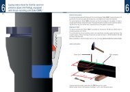
Laying instructions for ductile cast iron<br />
pressure pipes and fittings, equipped<br />
with thrust-resisting joint <strong>Düker</strong> SMU<br />
2446<br />
Dimensions L1 and L2 in mm<br />
DN<br />
40<br />
L1 Standard socket 161<br />
Long socket 200<br />
L 2<br />
169<br />
208<br />
Block strapping Gasket Gliding ring Locking ring Screw ring<br />
L 1 L 2<br />
L 1<br />
164<br />
203<br />
Insert Screw ring, locking ring, gliding ring and gasket in this sequence behind the centre punch<br />
marking L 2. Lubricate the pipe end, face of gasket, gliding ring and locking ring as well as the<br />
face and the screw thread of the screw ring with the lubricant supplied by the pipe manufacturer.<br />
Insert pipe end into the socket, centre it and check the installation depth L 1.<br />
Do not remove lifting gear yet.<br />
50<br />
L 2<br />
172<br />
211<br />
L 1<br />
170<br />
209<br />
65<br />
L 2<br />
178<br />
217<br />
Impress gasket with inserting device evenly into the socket (centering). Push gliding ring and<br />
locking ring until the gliding ring touches the gasket. Screw down screw ring with a hammer or<br />
ram as tighten as there is no turning of the screw ring possible anymore.<br />
100 mm<br />
Block strapping<br />
Check the correct installation depth:<br />
Block strapping must be within L2 ± 3 mm.<br />
After installation of the connection in centrical position, pipes can be deviated<br />
DN 80 – 200 up to 3 ° and<br />
DN 250 – 400 up to 2 °<br />
6245