catalogue - Düker GmbH & Co KGaA
catalogue - Düker GmbH & Co KGaA
catalogue - Düker GmbH & Co KGaA
- TAGS
- catalogue
- kgaa
- www.dueker.de

Create successful ePaper yourself
Turn your PDF publications into a flip-book with our unique Google optimized e-Paper software.
6 Laying<br />
230<br />
instructions for ductile cast iron<br />
pressure pipes, fittings and valves, equipped<br />
with thrust-resisting joint Novo SIT ®<br />
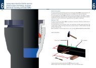
1. Cleaning inside the socket, particularly the TYTON ® -groove.<br />
2. Insert gasket (TYTON ® -ring) by deflecting and squeezing, so that the gasket is firmly bedded<br />
in its seating. The inner part of the inserted TYTON ® -ring should be slightly lubricated.<br />
3. Insert Novo SIT ® -ring into the pre-chamber.<br />
4. Cleaning of spigot-end, slightly lubricate and insert concentrically into the socket until it<br />
touches the TYTON ® -ring.<br />
5. Suitable tackles to push the spigot evenly into the socket have to be employed, f.e. laying tool<br />
V 300 D acc. to the illustration.<br />
Deviation should be avoided.<br />
Important:<br />
Changes of circumferential directions have to be arranged before connecting (f.e. installation<br />
of outlets, tees a.s.o.).<br />
Laying device V 300 D<br />
Alternately moving of levers<br />
draws spigot into the socket<br />
Locking<br />
Attention:<br />
After connecting both parts, the locking of the segments has to be accomplished by moving the<br />
levers in the opposite direction.<br />
The exact position of the TYTON ® -ring has to be tested with suitable gauge between the<br />
segments on the whole circumference.<br />
Gauge<br />
Note:<br />
Deviation of the installed thrust resisting joint is possible as follows:<br />
up to DN 400 – 3 °<br />
up to DN 700 – 2 °<br />
up to DN 800 – 1 °<br />
A pipe with 6 m length and 1° deflection deviates approx. 10 cm off the neutral pipe axis.<br />
Dismantling of thrust resisting joints<br />
Segment marking dots<br />
Push the spigot completely into the socket. Adjust dismantling blade to the outside diameter of the<br />
spigot, insert the blade into the hammering device, lubricate the blade slightly on both sides and drive<br />
the blades on all segments marking dots into the socket.<br />
Use pipe laying tool or dismantling collar to remove the sections from each other.<br />
Plates<br />
6231