catalogue - Düker GmbH & Co KGaA
catalogue - Düker GmbH & Co KGaA
catalogue - Düker GmbH & Co KGaA
- TAGS
- catalogue
- kgaa
- www.dueker.de

Create successful ePaper yourself
Turn your PDF publications into a flip-book with our unique Google optimized e-Paper software.
FITTINGS AND VALVES<br />
Fittings,<br />
Flanged pipes and<br />
Valves<br />
made of Ductile Cast Iron ( GGG )<br />
Index: (click with mouse)<br />
Fittings, flanged pipes and<br />
valves made of<br />
ductile cast iron (GGG)<br />
<strong>Düker</strong> in general<br />
Preamble<br />
The complete product range<br />
–> Index<br />
Location plan<br />
Flag / Addresses<br />
We designed the electronic version of our product <strong>catalogue</strong> user-friendly.<br />
In addition to useful information you will find the complete product range<br />
of <strong>Düker</strong> “fittings and valves”.<br />
To see each detailed information, please click within the index on the<br />
desired category.<br />
To get back to the Index please click on the blue area (chapter) at the top margin.<br />
http://www.dueker.de
4<br />
© 09.2011 E<br />
�<br />
Back to summary<br />
Hauptstraße 39–41, 63846 Laufach, Germany<br />
All rights reserved, including copying as a whole or in part.<br />
Differences in dimensions and weights and in the illustrations are possible.<br />
In the interest of technical progress, we reserve the right to implement changes and<br />
improvements to the products without previous announcement.<br />
<strong>Düker</strong> <strong>GmbH</strong> & <strong>Co</strong>. <strong>KGaA</strong><br />
Hauptstraße 39–41, 63846 Laufach, Germany<br />
Phone: + 49 60 93 / 87 -0<br />
Telefax: + 49 60 93 / 87 -246<br />
e-mail: info@dueker.de<br />
Internet: http://www.dueker.de<br />
Member of<br />
FGR / EADIPS-Group<br />
5
6<br />
�<br />
Back to summary<br />
<strong>Düker</strong> <strong>GmbH</strong> & <strong>Co</strong>. <strong>KGaA</strong><br />
In 1469, official documents mentioned a mine which was the origin of <strong>Düker</strong>.<br />
The foundry, enamelling works and mechanical construction are comprising a production area<br />
exceeding 80.000 sq. metres with approx. 700 employees.<br />
At Laufach / Spessart and Karlstadt / Main we are manufacturing products, used in:<br />
Drainage technology<br />
• Hubless drainage pipe systems<br />
• couplings for hubless drainage pipe systems<br />
Underground construction<br />
• pressure pipes<br />
• fittings and<br />
• valves<br />
Chemical industry<br />
Acid proof glass lined …<br />
• pipes<br />
• valves<br />
• special valves and<br />
• column<br />
Foundry engineering<br />
• centrifugal casting machines for all kinds of pipes and bushes<br />
• cokeless cupola furnaces and<br />
• complete foundry equipment<br />
Jobbing foundry<br />
• serial parts as well as individual castings in various cast iron qualities<br />
(GG + GGG), raw cast, machined or as finished product.<br />
7
8<br />
�<br />
Back to summary<br />
How to find <strong>Düker</strong> …<br />
9
10<br />
�<br />
Back to summary<br />
We keep on moving …<br />
Dear customer,<br />
dear business friends,<br />
we are glad to present you the new edition of our product <strong>catalogue</strong> for fittings,<br />
flanged pipes and valves made of ductile cast iron for underground construction.<br />
In addition to quality and reliability as well as to the extension and specifying<br />
of our product range we always assist you with planning, service and individual<br />
customer care.<br />
You can always depend on <strong>Düker</strong> consultants, technicians and designing engineers<br />
regarding questions, particular tasks and demands. Of course we also appreciate<br />
your incitations and criticism.<br />
Demand us – give us a call!<br />
Sales manager<br />
Phone: +49 (0) 60 93 / 87 – 0<br />
11
12<br />
To page down within the categories<br />
please use the navigation bar<br />
of the acrobat-reader as well.<br />
Index<br />
Description <strong>Co</strong>de Page<br />
1 Ductile cast iron (GGG) flanged pipes and fittings<br />
acc. to ISO 2531, DIN EN 545 and<br />
manufacturer’s standard 21<br />
1.1 Socket joints 23<br />
TYTON ® -socket joint TYT 25<br />
Screw-gland socket joint S MU 26<br />
Bolted-gland socket joint STB 27<br />
Mechanical joint socket and glands 28<br />
Rotatable flanges 29<br />
1.2 Restrained socket joints<br />
made of ductile cast iron 31<br />
TYTON ® -socket joint<br />
with Tyton SIT ® 33<br />
TYTON ® -socket joint<br />
with TYTON SIT PLUS ® ( TSP ® ) 34<br />
Novo-socket joint<br />
with Novo SIT ® 35<br />
Restrained socket joints for plastic pipelines<br />
with Novo GRIP ® III 36<br />
Screw-gland socket joints<br />
with <strong>Düker</strong>-thrust resisting joint SMU 37<br />
with <strong>Düker</strong> SPEZIAL 38<br />
1.3 Flanged joints acc. to DIN EN 1092-2 41<br />
Flanged joints PN 10 42 – 43<br />
Flanged joints PN 16 44 – 45<br />
Flanged joints PN 25 46 – 47<br />
Flanged joints PN 40 48 – 49<br />
13
14<br />
Index<br />
Description <strong>Co</strong>de Page<br />
Hexagonal screws for flanges PN 10 and PN 16 50<br />
Hexagonal screws for flanges PN 25 and PN 40 51<br />
Flat gaskets for flanges 52<br />
Arrangement of boltholes 53<br />
1.4 Ductile cast iron (GGG) flanged pressure pipes 55<br />
1.4.1 Pressure pipes with cast-on flanges FFG 57 – 59<br />
1.4.2 Weight of pressure pipes with cast-on flanges FFG 61 – 63<br />
1.5 Ductile cast iron (GGG) fittings 65<br />
Information about ductile cast iron fittings 67<br />
Marking for ductile cast iron fittings 68 – 69<br />
Flanged sockets type a) E 70 – 71<br />
Flanged sockets type b) EU 72 – 73<br />
Flanged spigots F 74<br />
<strong>Co</strong>llars U 75<br />
Single socket bends 90° MQ 76<br />
Double socket bends 90° MMQ 77<br />
Single socket bends 45° MK 45 78<br />
Double socket bends 45° MMK 45 79<br />
Single socket bends 30° MK 30 80<br />
Double socket bends 30° MMK 30 81<br />
Single socket bends 22 1/2 ° MK 22 82<br />
Double socket bends 22 1/2 ° MMK 22 83<br />
Single socket bends 11 1/4 ° MK 11 84<br />
Double socket bends 11 1/4 ° MMK 11 85<br />
Double socket tees with flanged branch MMA 86 – 91<br />
All socket tees MMB 92 – 96<br />
Double socket pieces with 45° socket branch MMC 97 – 98<br />
Index<br />
Description <strong>Co</strong>de Page<br />
… Ductile cast iron (GGG) fittings<br />
Double socket tapers MMR 99 – 101<br />
Single socket tees with spigot and flanged branch A 102 – 103<br />
Single socket tees with spigot and socket branch B 104<br />
Double flanged bends 90° Q 105<br />
Double flanged duckfoot bends 90° N 106<br />
Double flanged bends 45° FFK 45 107<br />
Double flanged bends 30° FFK 30 108<br />
Double flanged bends 22 1/2 ° FFK 22 109<br />
Double flanged bends 11 1/4 ° FFK 11 110<br />
All flanged tees T 111 – 116<br />
Double flanged pieces with 45° flanged branch FFC 117 – 119<br />
All flanged cross tees TT 120 – 122<br />
Double flanged tapers concentric FFR 123 – 125<br />
Double flanged tapers excentric FFRe 126 – 127<br />
Single flange bell 128 – 129<br />
Blank flanges X 130 – 131<br />
Blank flanges with tap hole XG 132 – 133<br />
Pipe caps with TYTON ® -socket O 134 – 135<br />
<strong>Co</strong>nversion flanges DN 80 4/8 holes 136<br />
Flanged socket duckfoot bends 90° EN 137<br />
Double socket duckfoot bends 90° with Novo-sockets MMN / MMNR 138<br />
Plugs for screw-gland and TYTON ® -sockets P 139<br />
Screw rings for plugs 140<br />
Screw plugs for screw-gland socket PX 141<br />
Double flanged hatchboxes 142<br />
15
16<br />
Index<br />
Description <strong>Co</strong>de Page<br />
1.6 Ductile cast iron (GGG) special fittings 143 – 145<br />
Single socket pieces with angled branch 45 ° C<br />
Socket-spigot tapers R<br />
Flanged socket bends 90 ° EQ<br />
2 Ductile cast iron (GGG) fittings<br />
for plastic pipelines (KS-fittings) 147<br />
Remarks 149<br />
Flanged sockets E-KS 150<br />
Flanged spigots F-KS 151<br />
Flanged socket duckfoot bends 90° EN-KS 152<br />
Double socket tees with flanged branch MMA-KS 153 – 154<br />
All socket tees MMB-KS 155<br />
Double socket tapers MMR-KS 156<br />
Double sockets with internal threaded branch MMI-KS 157 – 158<br />
3 Inside and outside protection 159<br />
Cement mortar/enamel 161<br />
Epoxy resin/special coatings 161<br />
4 Accessories 163<br />
Laying tool for pipes, fittings and valves with<br />
TYTON ® -socket V 300 D 165<br />
Hook wrench for screw-gland joints 166<br />
5 Valves 167<br />
Gate valves resilient seated for water and gas<br />
– Type 4004 with flanges 170 – 171<br />
– Type 2004 with flanges 172 – 173<br />
Index<br />
Description <strong>Co</strong>de Page<br />
… Gate valves resilient seated for water and gas<br />
– Type 4004 with Novo-sockets 174 – 175<br />
– Type 4004 with screw-gland sockets 176 – 177<br />
– Type 4004 with Novo-socket and spigot 178 – 179<br />
– Type 2004 with flange and socket 180 – 181<br />
– Type 4004 for PE-HD-connection 182 – 183<br />
– Type 4004 with rotatable flanges 184 – 185<br />
– Type 1004 for PE-HD-connection 186 – 187<br />
– Type 1004 with pipe threads 188 – 189<br />
– Type 1004 with flange / PE-HD-connection 190 – 191<br />
– Type 1004 with internal thread / PE-HD-connection 192 – 193<br />
Gate valves resilient seated for gas<br />
– Type 3004 with weld-on ends 194 – 195<br />
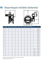
Butterfly valves with flanges and sliding crank gear 196 – 199<br />
Butterfly valves with Novo-sockets and<br />
sliding crank gear 200 – 201<br />
Underground hydrants<br />
– Type 304 / 305 with flange 202 – 203<br />
– Type 393 S for push-in connection 204 – 205<br />
17
18<br />
Index<br />
Description <strong>Co</strong>de Page<br />
Pillar hydrants<br />
– Type 494 206 – 207<br />
– Type 495 with valve head 208 – 209<br />
– Type 501, adjustable 210 – 211<br />
Duckfoot bends 90 ° with Novo-sockets 212<br />
<strong>Co</strong>llars with Novo-sockets 213<br />
All spigot tees and single socket tees<br />
for gate valves with socket connection 214 – 215<br />
Tapping sleeves<br />
– TOP (for top mounting) and<br />
– TOPsi (for side mounting) 216 – 217<br />
– TOP with PE-HD-connection 218 – 219<br />
Tapping clamp Fig. 88 and 89 220<br />
Clamping bands for tapping clamps type 88 and 89<br />
and for tapping valves “TOP” and “TOPsi” 221<br />
Flap valves 222 – 223<br />
Operating T-keys for valves 224<br />
Index<br />
Description <strong>Co</strong>de Page<br />
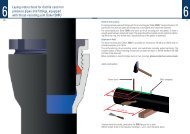
6 Laying instructions for thrust-resisting joints<br />
Mounting instructions for flanges 225<br />
6.1 Laying instructions for thrust-resisting joints<br />
Laying instructions for ductile cast iron pressure pipes<br />
and fittings with thrust resisting joint …<br />
227<br />
– Novo SIT ® 228 – 231<br />
– Tyton SIT ® 232 – 235<br />
– TYTON SIT PLUS ® ( TSP ® ) 236 – 241<br />
– SMU 242 – 245<br />
– <strong>Düker</strong> SPEZIAL<br />
… Laying instructions for thrust-resisting joints<br />
Laying instructions for ductile cast iron pressure pipes<br />
and fittings to connect with plastic pipes with thrust<br />
resisting joint …<br />
246 – 249<br />
– Novo GRIP ® III 250 – 253<br />
6.2 Assembly instructions for pressure pipes<br />
and fittings with flanges<br />
Assembly instructions for pressure pipes<br />
255<br />
and fittings with flanges 257 – 259<br />
19
20<br />
�<br />
Back to summary<br />
1<br />
Ductile cast iron (GGG)<br />
flanged pipes and fittings<br />
1<br />
– ISO 2531 and DIN EN 545<br />
– Manufacturer’s standard
22<br />
�<br />
Back to summary<br />
1.1<br />
Socket joints<br />
for pipes and fittings<br />
made of ductile cast iron ( GGG )<br />
1.1
24<br />
TYTON ® -socket joints ( TYT )<br />
acc. to DIN 28 603<br />
Socket for fittings<br />
Socket Dimensions for flanged and weights sockets and collars Socket for pipes<br />
Dimensions in mm Weight in kg ≈ socket<br />
Flanged<br />
DN ø d1 ø D t Pipes Fittings sockets<br />
80<br />
100<br />
125<br />
150<br />
200<br />
250<br />
300<br />
350<br />
400<br />
450*<br />
500<br />
600<br />
700<br />
800<br />
900<br />
1000<br />
1200<br />
98<br />
118<br />
144<br />
170<br />
222<br />
274<br />
326<br />
378<br />
429<br />
480<br />
532<br />
635<br />
738<br />
842<br />
945<br />
1048<br />
1255<br />
* acc. to manufacturer’s standard<br />
141<br />
161<br />
188<br />
215<br />
271<br />
324<br />
381<br />
434<br />
489<br />
541,5<br />
598<br />
707<br />
825<br />
935<br />
1042<br />
1150<br />
1368<br />
84<br />
88<br />
91<br />
94<br />
100<br />
105<br />
110<br />
110<br />
110<br />
120<br />
120<br />
120<br />
150<br />
160<br />
175<br />
185<br />
215<br />
3,4<br />
4,3<br />
5,7<br />
7,1<br />
10,3<br />
14,2<br />
18,6<br />
23,7<br />
29,3<br />
37,8<br />
42,8<br />
59,3<br />
79,1<br />
102,6<br />
129,9<br />
161,3<br />
—<br />
2,8<br />
3,3<br />
4,5<br />
5,6<br />
8,0<br />
11,1<br />
14,3<br />
17,1<br />
20,8<br />
27,6<br />
31,7<br />
42,3<br />
71,2<br />
95,4<br />
150,3<br />
186,9<br />
250,0<br />
2,4<br />
3,1<br />
4,0<br />
4,9<br />
7,1<br />
9,7<br />
12,5<br />
15,2<br />
18,6<br />
24,3<br />
27,6<br />
36,2<br />
59,1<br />
79,8<br />
122,7<br />
152,1<br />
193,0<br />
Gasket<br />
0,13<br />
0,16<br />
0,19<br />
0,22<br />
0,37<br />
0,48<br />
0,67<br />
0,77<br />
1,09<br />
1,40<br />
1,60<br />
2,29<br />
4,00<br />
5,20<br />
6,50<br />
8,00<br />
9,50<br />
125
1 Screw-gland<br />
26<br />
socket joints ( SMU ) PN 16 1)<br />
acc. to DIN 28 601<br />
Socket for fittings<br />
Bolted-gland socket joints ( STB ) PN 16 1)<br />
acc. to DIN 28 602<br />
Socket for flanged sockets and collars Socket for pipes Socket for pipes and fittings Socket for flanged sockets<br />
Dimensions and weights<br />
Dimensions and weights<br />
Dimensions in mm Weight in kg ≈ socket<br />
Dimensions in mm Weight in kg ≈ socket<br />
Flanged Screw Gliding<br />
Flanged Bolted-<br />
Hammer<br />
DN<br />
40<br />
ø d1 56<br />
ø D<br />
101<br />
t<br />
74<br />
Pipes<br />
—<br />
Fittings<br />
1,4<br />
sockets<br />
1,3<br />
ring<br />
0,84<br />
ring<br />
0,05<br />
Gasket<br />
0,06<br />
DN ø d1 ø D t ø d2 l n Pipes Fittings<br />
sockets<br />
collars<br />
gland<br />
ring Gasket<br />
head<br />
screws<br />
50 66 113 77 — 1,8 1,6 0,90 0,06 0,08<br />
100* 118 235 116 M 20 80 4 — — — 2,7 0,10 0,24<br />
65 82 129 80 — 2,2 1,9 1,30 0,06 0,10<br />
150* 170 290 118 M 20 80 8 — — — 4,0 0,20 0,24<br />
80 98 146 84 3,4 2,8 2,4 1,40 0,07 0,12<br />
200* 222 345 121 M 20 80 8 — — — 5,0 0,27 0,24<br />
100 118 166 88 4,3 3,3 3,1 1,90 0,08 0,15<br />
250* 274 400 124 M 20 80 8 — — — 6,0 0,50 0,24<br />
125 144 197 91 5,7 4,5 4,0 3,00 0,10 0,19<br />
300* 326 460 127 M 20 90 8 — — 18,7 7,1 0,60 0,27<br />
150 170 224 94 7,1 5,6 4,9 3,20 0,11 0,23<br />
350* 378 515 129 M 20 90 12 — 26,6 22,9 9,6 0,70 5,5<br />
200 222 280 100 10,3 8,0 7,1 4,50 0,17 0,36<br />
400* 429 570 132 M 20 90 12 29,3 32,2 27,6 10,6 0,80 5,5<br />
250 274 336 106 14,2 11,1 9,7 6,30 0,21 0,50<br />
450* 480 625 135 M 20 100 12 42,8 45,3 38,7 13,0 1,00 6,0<br />
300 326 391 110 18,6 14,3 12,5 8,10 0,30 0,66<br />
500 532 680 138 M 20 100 16 42,8 45,3 38,7 15,0 1,00 7,7<br />
350 378 450 113 23,7 18,6 16,2 10,50 0,35 0,84<br />
600 635 790 143 M 20 100 16 59,3 61,2 52,2 20,9 1,50 7,7<br />
400 429 503 116 29,3 22,2 19,5 13,50 0,40 1,05<br />
700 738 900 149 M 20 110 20 79,1 80,0 67,9 27,2 1,90 10,0<br />
450* 480 572 164 — —<br />
25,00 0,60 1,50<br />
800 842 1010 154 M 20 110 24 102,6 101,0 85,4 34,1 2,30 12,0<br />
500* 532 626 174 — — 28,5 31,50 0,87 1,85<br />
900 945 1125 160 M 20 120 24 129,9 128,0 108,4 44,0 2,80 12,0<br />
1000 1048 1250 165 M 24 120 24 161,3 162,9 138,7 57,0 3,30 13,0<br />
1200 1255 1450 176 M 24 130 28 237,9 232,4 196,5 75,0 3,80 18,0<br />
* acc. to manufacturer’s standard 1) higher pressures on request<br />
* acc. to manufacturer’s standard 1) higher pressures on request<br />
127
281 Mechanical joint socket and glands<br />
Dimensions and weights<br />
DN<br />
80<br />
100<br />
125*<br />
150<br />
200<br />
250<br />
300<br />
350*<br />
400*<br />
450*<br />
500*<br />
600*<br />
ø d1<br />
mm<br />
98<br />
118<br />
144<br />
170<br />
222<br />
274<br />
326<br />
378<br />
429<br />
480<br />
532<br />
635<br />
ø d2<br />
mm<br />
22<br />
22<br />
22<br />
22<br />
22<br />
22<br />
22<br />
22<br />
22<br />
27<br />
27<br />
27<br />
All dimensions are in mm * in preparation<br />
ø d3<br />
mm<br />
101<br />
121<br />
147<br />
173<br />
225<br />
277<br />
329<br />
381<br />
432<br />
483<br />
535<br />
638<br />
t<br />
mm<br />
90<br />
92<br />
95<br />
98<br />
104<br />
104<br />
105<br />
108<br />
110<br />
113<br />
115<br />
120<br />
Weight gland<br />
kg<br />
2,7<br />
3,4<br />
3,6<br />
5,0<br />
6,0<br />
6,9<br />
8,7<br />
11,3<br />
12,0<br />
16,5<br />
19,5<br />
26,0<br />
Rotatable flanges<br />
Dimensions and weights<br />
DN PN<br />
ø D<br />
mm<br />
80 10/16 200<br />
100 10/16 220<br />
125* 10/16 250<br />
150 10/16 285<br />
200 10 340<br />
16 340<br />
250 10 395<br />
16 400<br />
300 10 455<br />
16 455<br />
350* 10 505<br />
16 520<br />
400* 10 565<br />
16 580<br />
450* 10 615<br />
16 640<br />
500* 10 670<br />
16 715<br />
600* 10 780<br />
16 840<br />
All dimensions are in mm * in preparation<br />
a<br />
mm<br />
23<br />
23<br />
24,5<br />
26<br />
29<br />
29<br />
32<br />
32<br />
36<br />
36<br />
39<br />
39<br />
42<br />
42<br />
45<br />
45<br />
48<br />
48<br />
55<br />
55<br />
c<br />
mm<br />
3<br />
3<br />
3<br />
3<br />
3<br />
3<br />
3<br />
3<br />
4<br />
4<br />
4<br />
4<br />
4<br />
4<br />
4<br />
4<br />
4<br />
4<br />
5<br />
5<br />
ø K<br />
mm<br />
160<br />
180<br />
210<br />
240<br />
295<br />
295<br />
350<br />
355<br />
400<br />
410<br />
460<br />
470<br />
515<br />
525<br />
565<br />
585<br />
620<br />
650<br />
725<br />
770<br />
Weight flange<br />
kg<br />
2,0<br />
2,2<br />
3,0<br />
4,2<br />
6,2<br />
6,2<br />
8,4<br />
7,6<br />
10,8<br />
11,0<br />
14,6<br />
14,2<br />
16,8<br />
18,2<br />
15,2<br />
18,2<br />
18,2<br />
29,0<br />
129
30<br />
1.2<br />
Restrained socket joints<br />
made of ductile cast iron<br />
1.2
32<br />
TYTON ® -socket joints<br />
with Tyton SIT ®<br />
Dimensions and weights<br />
DN<br />
80<br />
100<br />
125<br />
150<br />
200<br />
250<br />
300<br />
400<br />
Number of<br />
retaining<br />
segments<br />
4<br />
5<br />
5<br />
7<br />
10<br />
15<br />
20<br />
30<br />
allowable<br />
operating pressure<br />
PFA<br />
16<br />
16<br />
16<br />
16<br />
16<br />
10<br />
10<br />
10<br />
Deflection<br />
max.<br />
3 °<br />
3 °<br />
3 °<br />
3 °<br />
3 °<br />
3 °<br />
3 °<br />
3 °<br />
Assembling acc. laying instruction for thrust-resisting joint Tyton SIT ® , page 232 – 235<br />
Weight in kg ≈<br />
Tyton SIT ® -<br />
gasket<br />
0,17<br />
0,19<br />
0,23<br />
0,27<br />
0,45<br />
0,60<br />
0,92<br />
1,58<br />
133
1 TYTON<br />
34<br />
® -socket joints<br />
with TYTON SIT PLUS ®<br />
Dimensions and weights<br />
DN<br />
80<br />
100<br />
125<br />
150<br />
200<br />
250<br />
300<br />
350<br />
400<br />
500<br />
600<br />
Number of<br />
retaining<br />
segments<br />
4<br />
5<br />
5<br />
7<br />
10<br />
15<br />
20<br />
25<br />
28<br />
35<br />
42<br />
allowable<br />
operating pressure<br />
PFA<br />
32<br />
32<br />
25<br />
25<br />
25<br />
25<br />
25<br />
25<br />
16<br />
16<br />
10<br />
Deflection<br />
max.<br />
3 °<br />
3 °<br />
3 °<br />
3 °<br />
3 °<br />
3 °<br />
3 °<br />
3 °<br />
2 °<br />
2 °<br />
2 °<br />
Assembling acc. laying instruction for thrust-resisting joint TYTON SIT PLUS ® , page 236 – 241<br />
Weight in kg ≈<br />
TYTON SIT PLUS ® -<br />
gasket<br />
0,14<br />
0,16<br />
0,20<br />
0,23<br />
0,45<br />
0,60<br />
0,95<br />
1,25<br />
1,50<br />
2,30<br />
3,00<br />
Novo-socket joints<br />
with Novo SIT ®<br />
allowable<br />
operating<br />
pressure<br />
DN d1 D t PFA<br />
80 98 141 119 25<br />
100 118 161 123<br />
125 140 188 126<br />
150 170 215 129<br />
200 222 271 138<br />
250 274 324 143<br />
300 326 381 152<br />
350 378 434 154<br />
400 429 505 154<br />
450 480 572 164<br />
500 532 598 168<br />
600 635 707 168<br />
700 738 824 205<br />
800 842 934 217<br />
1)<br />
25 1)<br />
25 1)<br />
25 1)<br />
25 1)<br />
25 1)<br />
25 1)<br />
16 2)<br />
16 2)<br />
16 2)<br />
16 2)<br />
16 2)<br />
10 2)<br />
10 3)<br />
Dimensions and weights<br />
Dimensions in mm Weight in kg ≈<br />
Novo<br />
Deflection Pre-chamber<br />
max.<br />
3 ° 1,2<br />
3 ° 1,4<br />
3 ° 1,8<br />
3 ° 2,1<br />
3 ° 3,1<br />
3 ° 4,8<br />
3 ° 5,7<br />
3 ° 6,4<br />
3 ° 8,3<br />
3 ° 9,5<br />
2 ° 12,0<br />
2 ° 16,6<br />
2 ° 29,5<br />
1 ° 36,6<br />
Assembling acc. laying instruction for thrust-resisting joint Novo SIT ® , page 228 – 231<br />
1) up to PN 40 on request 2) up to PN 25 on request 3) up to PN 16 on request<br />
Novo SIT ®<br />
ring<br />
0,15<br />
0,20<br />
0,25<br />
0,35<br />
0,65<br />
0,80<br />
1,00<br />
1,30<br />
1,50<br />
2,00<br />
2,50<br />
3,00<br />
3,50<br />
3,60<br />
135
136<br />
Restrained socket joints<br />
for plastic-pipelines<br />
with Novo GRIP ® III<br />
DN<br />
80<br />
100<br />
125<br />
150<br />
200<br />
Locking-ring<br />
Dimensions and weights<br />
ø d1 90<br />
110<br />
140<br />
160<br />
225<br />
<strong>Co</strong>mpression-ring<br />
Dimensions in mm<br />
t<br />
119<br />
123<br />
126<br />
129<br />
138<br />
Gasket (GKS)<br />
Assembling acc. laying instruction for thrust-resisting joint Novo GRIP ® III, page 250 – 253<br />
allowable operating pressure<br />
PFA<br />
10 / 16<br />
10 / 16<br />
10 / 16<br />
10 / 16<br />
10 / 16<br />
Screw-gland socket joints<br />
with DÜKER thrust-resisting joint SMU DN 40 – DN 65<br />
Dimensions and weights<br />
allowable operating pressure<br />
DN<br />
PFA<br />
40*<br />
16<br />
50*<br />
16<br />
65*<br />
16<br />
Deflection<br />
max.<br />
3 °<br />
3 °<br />
3 °<br />
Assembling acc. laying instruction for thrust-resisting joint SMU, page 242 – 245<br />
Weight in kg ≈<br />
locking ring<br />
0,075<br />
0,100<br />
0,140<br />
137
381<br />
Screw-gland socket joints<br />
with thrust-resisting joint <strong>Düker</strong> SPEZIAL<br />
DN 80 – DN 400<br />
Dimensions and weights<br />
DN<br />
80<br />
100<br />
125<br />
150<br />
200<br />
250<br />
300<br />
400<br />
DN 80 – 250 Locking ring<br />
DN 300 – 400 Segment ring<br />
allowable<br />
operating pressure<br />
PFA<br />
16<br />
16<br />
16<br />
16<br />
16<br />
16<br />
16<br />
16<br />
Deflection<br />
max.<br />
3 °<br />
3 °<br />
3 °<br />
3 °<br />
3 °<br />
2 °<br />
2 °<br />
2 °<br />
Weight in kg ≈<br />
SPEZIAL-screw ring and<br />
Locking ring<br />
Segment ring<br />
0,22<br />
—<br />
0,26<br />
—<br />
0,31<br />
—<br />
0,37<br />
—<br />
0,52<br />
—<br />
0,67<br />
—<br />
—<br />
10,35<br />
—<br />
16,00<br />
Assembling acc. laying instruction for thrust-resisting joint <strong>Düker</strong> SPEZIAL, page 246 – 249<br />
1.3<br />
Flanged joints<br />
acc. to DIN EN 1092-2<br />
1.3<br />
resp. ISO 7005-2
40<br />
Flanged joints from PN 10 up to PN 40<br />
acc. to DIN EN 1092-2<br />
141
142<br />
Flanged joints PN 10<br />
acc. to DIN EN 1092-2<br />
Flanged joints PN 10<br />
acc. to DIN EN 1092-2<br />
Dimensions and weights PN 10<br />
DN<br />
40<br />
50<br />
65<br />
80<br />
100<br />
125<br />
150<br />
200<br />
250<br />
300<br />
350<br />
400<br />
450<br />
500<br />
600<br />
700<br />
800<br />
900<br />
1000<br />
1200<br />
Pipe<br />
ø d1 56<br />
66<br />
82<br />
98<br />
118<br />
144<br />
170<br />
222<br />
274<br />
326<br />
378<br />
429<br />
480<br />
532<br />
635<br />
738<br />
842<br />
945<br />
1048<br />
1255<br />
* n = number of bolt holes<br />
Dimensions in mm<br />
Flange Neck Raised face<br />
ø D C ø K n* ø L ø N h ø d f<br />
150 19,0 110 4 19 70 39,0 84 3<br />
165 19,0 125 4 19 84 40,0 99 3<br />
185 19,0 145 4 19 104 41,5 118 3<br />
200 19,0 160 8 19 120 43,0 132 3<br />
220 19,0 180 8 19 140 45,0 156 3<br />
250 19,0 210 8 19 170 47,5 184 3<br />
285 19,0 240 8 23 190 50,0 211 3<br />
340 20,0 295 8 23 246 55,0 266 3<br />
400 22,0 350 12 23 298 60,0 319 3<br />
455 24,5 400 12 23 348 65,0 370 4<br />
505 24,5 460 16 23 408 70,0 429 4<br />
565 24,5 515 16 28 456 75,0 480 4<br />
615 25,5 565 20 28 502 80,0 530 4<br />
670 26,5 620 20 28 559 85,0 582 4<br />
780 30,0 725 20 31 658 95,0 682 5<br />
895 32,5 840 24 31 772 105,0 794 5<br />
1015 35,0 950 24 34 876 115,0 901 5<br />
1115 37,5 1050 28 34 976 125,0 1001 5<br />
1230 40,0 1160 28 37 1080 135,0 1112 5<br />
1455 45,0 1380 32 41 1292 155,0 1328 5<br />
Weight<br />
in kg ≈<br />
1,7<br />
2,1<br />
2,6<br />
2,8<br />
3,3<br />
4,0<br />
5,0<br />
6,9<br />
9,8<br />
13,0<br />
14,7<br />
17,2<br />
20,0<br />
23,2<br />
32,8<br />
44,3<br />
58,8<br />
69,6<br />
87,6<br />
121,0<br />
143
1 Flanged<br />
44<br />
joints PN 16<br />
acc. to DIN EN 1092-2<br />
Flanged joints PN 16<br />
acc. to DIN EN 1092-2<br />
Dimensions and weights PN 16<br />
DN<br />
40<br />
50<br />
65<br />
80<br />
100<br />
125<br />
150<br />
200<br />
250<br />
300<br />
350<br />
400<br />
450<br />
500<br />
600<br />
700<br />
800<br />
900<br />
1000<br />
1200<br />
Pipe<br />
ø d1 56<br />
66<br />
82<br />
98<br />
118<br />
144<br />
170<br />
222<br />
274<br />
326<br />
378<br />
429<br />
480<br />
532<br />
635<br />
738<br />
842<br />
945<br />
1048<br />
1255<br />
* n = number of bolt holes<br />
Dimensions in mm<br />
Flange Neck Raised face<br />
ø D C ø K n* ø L ø N h ø d f<br />
150 19,0 110 4 19 70 39,0 84 3<br />
165 19,0 125 4 19 84 40,0 99 3<br />
185 19,0 145 4 19 104 41,5 118 3<br />
200 19,0 160 8 19 120 43,0 132 3<br />
220 19,0 180 8 19 140 45,0 156 3<br />
250 19,0 210 8 19 170 47,5 184 3<br />
285 19,0 240 8 23 190 50,0 211 3<br />
340 20,0 295 12 23 246 55,0 266 3<br />
400 22,0 355 12 28 296 60,0 319 3<br />
455 24,5 410 12 28 350 65,0 370 4<br />
520 26,5 470 16 28 410 70,0 429 4<br />
580 28,0 525 16 31 458 75,0 480 4<br />
640 30,0 585 20 31 516 80,0 548 4<br />
715 31,5 650 20 34 576 85,0 609 4<br />
840 36,0 770 20 37 690 95,0 720 5<br />
910 39,5 840 24 37 760 105,0 794 5<br />
1025 43,0 950 24 41 862 115,0 901 5<br />
1125 46,5 1050 28 41 962 125,0 1001 5<br />
1255 50,0 1170 28 44 1076 135,0 1112 5<br />
1485 57,0 1390 32 50 1282 155,0 1328 5<br />
Weight<br />
in kg ≈<br />
1,7<br />
2,1<br />
2,6<br />
2,8<br />
3,3<br />
4,0<br />
5,0<br />
6,7<br />
9,4<br />
12,6<br />
17,5<br />
22,1<br />
30,2<br />
37,4<br />
57,6<br />
57,4<br />
76,8<br />
91,4<br />
127,0<br />
185,0<br />
145
1 Flanged<br />
46<br />
joints PN 25<br />
acc. to DIN EN 1092-2<br />
Flanged joints PN 25<br />
acc. to DIN EN 1092-2<br />
Dimensions and weights PN 25<br />
DN<br />
40<br />
50<br />
65<br />
80<br />
100<br />
125<br />
150<br />
200<br />
250<br />
300<br />
350<br />
400<br />
450<br />
500<br />
600<br />
700<br />
800<br />
900<br />
1000<br />
1200<br />
Pipe<br />
ø d1 56<br />
66<br />
82<br />
98<br />
118<br />
144<br />
170<br />
222<br />
274<br />
326<br />
378<br />
429<br />
480<br />
532<br />
635<br />
738<br />
842<br />
945<br />
1048<br />
1255<br />
* n = number of bolt holes<br />
Dimensions in mm<br />
Flange Neck Raised face<br />
ø D C ø K n* ø L ø N h ø d f<br />
150 19,0 110 4 19 70 39 84 3<br />
165 19,0 125 4 19 84 40 99 3<br />
185 19,0 145 8 19 104 41,5 118 3<br />
200 19,0 160 8 19 120 43 132 3<br />
235 19,0 190 8 23 142 45 156 3<br />
270 19,0 220 8 28 162 47,5 184 3<br />
300 20,0 250 8 28 192 50 211 3<br />
360 22,0 310 12 28 252 55 274 3<br />
425 24,5 370 12 31 304 60 330 3<br />
485 27,5 430 16 31 364 65 389 4<br />
555 30,0 490 16 34 418 70 448 4<br />
620 32,0 550 16 37 472 75 503 4<br />
670 34,5 600 20 37 520 80 548 4<br />
730 36,5 660 20 37 580 85 609 4<br />
845 42,0 770 20 41 684 95 720 5<br />
960 46,5 875 24 44 780 105 820 5<br />
1085 51,0 990 24 50 882 115 928 5<br />
1185 55,5 1090 28 50 982 125 1028 5<br />
1320 60,0 1210 28 57 1086 135 1140 5<br />
1530 69,0 1420 32 57 1296 155 1350 5<br />
Weight<br />
in kg ≈<br />
1,7<br />
2,1<br />
2,4<br />
2,8<br />
3,8<br />
4,7<br />
6,0<br />
8,7<br />
13,0<br />
17,7<br />
25,4<br />
33,2<br />
40,2<br />
47,2<br />
71,5<br />
90,0<br />
123,0<br />
149,0<br />
201,0<br />
285,0<br />
147
481<br />
Flanged joints PN 40<br />
acc. to DIN EN 1092-2<br />
Flanged joints PN 40<br />
acc. to DIN EN 1092-2<br />
Dimensions and weights PN 40<br />
DN<br />
40<br />
50<br />
65<br />
80<br />
100<br />
125<br />
150<br />
200<br />
250<br />
300<br />
350<br />
400<br />
450<br />
500<br />
600<br />
Pipe<br />
ø d1 56<br />
66<br />
82<br />
98<br />
118<br />
144<br />
170<br />
222<br />
274<br />
326<br />
378<br />
429<br />
480<br />
532<br />
635<br />
ø D<br />
150<br />
165<br />
185<br />
200<br />
235<br />
270<br />
300<br />
375<br />
450<br />
515<br />
580<br />
660<br />
685<br />
755<br />
890<br />
* n = number of bolt holes<br />
Dimensions in mm<br />
Flange Neck Raised face<br />
C ø K n* ø L ø N h ø d f<br />
19,0 110 4 19 70 39,0 84 3<br />
19,0 125 4 19 84 40,0 99 3<br />
19,0 145 8 19 104 41,5 118 3<br />
19,0 160 8 19 120 43,0 132 3<br />
19,0 190 8 23 142 45,0 156 3<br />
23,5 220 8 28 162 47,5 184 3<br />
26,0 250 8 28 192 50,0 211 3<br />
30,0 320 12 31 254 55,0 284 3<br />
34,5 385 12 34 312 60,0 345 3<br />
39,5 450 16 34 378 65,0 409 4<br />
44,0 510 16 37 432 70,0 465 4<br />
48,0 585 16 41 498 75,0 535 4<br />
49,0 610 20 41 522 80,0 560 4<br />
52,0 670 20 44 576 85,0 615 4<br />
58,0 795 20 50 686 95,0 735 5<br />
Weight<br />
in kg ≈<br />
1,7<br />
2,1<br />
2,4<br />
2,8<br />
3,8<br />
5,9<br />
8,0<br />
14,0<br />
23,5<br />
33,5<br />
43,0<br />
62,0<br />
57,0<br />
82,0<br />
124,0<br />
149
1 Hexagonal<br />
50<br />
screws for flanges<br />
PN 10 and PN 16<br />
acc. to DIN EN 1092-2<br />
PN 10<br />
PN 16<br />
Dimensions in mm Dimensions in mm<br />
DN ø d1 l1* l2** number ø d1 l1* l2** number<br />
40 M 16 80 80 4 M 16 80 80 4<br />
50 M 16 80 80 4 M 16 80 80 4<br />
65 M 16 80 80 4 M 16 80 80 4<br />
80 M 16 80 80 8 M 16 80 80 8<br />
100 M 16 80 80 8 M 16 80 80 8<br />
125 M 16 80 80 8 M 16 80 80 8<br />
150 M 20 80 90 8 M 20 80 90 8<br />
200 M 20 80 90 8 M 20 80 90 12<br />
250 M 20 90 90 12 M 24 90 100 12<br />
300 M 20 90 90 12 M 24 100 100 12<br />
350 M 20 90 90 16 M 24 100 110 16<br />
400 M 24 100 100 16 M 27 110 110 16<br />
450 M 24 100 110 20 M 27 110 120 20<br />
500 M 24 100 110 20 M 30 120 120 20<br />
600 M 27 110 120 20 M 33 130 140 20<br />
700 M 27 120 120 24 M 33 140 150 24<br />
800 M 30 130 130 24 M 36 150 160 24<br />
900 M 30 130 140 28 M 36 160 160 28<br />
1000 M 33 140 150 28 M 39 170 180 28<br />
1200 M 36 160 160 32 M 45 190 200 32<br />
l1* = Screw length for connection with one washer l2** = Screw length for connection with two washers<br />
Hexagonal screws for flanges<br />
PN 25 and PN 40<br />
acc. to DIN EN 1092-2<br />
DN<br />
40<br />
50<br />
65<br />
80<br />
100<br />
125<br />
150<br />
200<br />
250<br />
300<br />
350<br />
400<br />
450<br />
500<br />
600<br />
700<br />
800<br />
900<br />
1000<br />
1200<br />
ø d1 M 16<br />
M 16<br />
M 16<br />
M 16<br />
M 20<br />
M 24<br />
M 24<br />
M 24<br />
M 27<br />
M 27<br />
M 30<br />
M 33<br />
M 33<br />
M 33<br />
M 36<br />
M 39<br />
M 45<br />
M 45<br />
M 52<br />
M 52<br />
PN 25<br />
PN 40<br />
Maße in mm Maße in mm<br />
l1*<br />
80<br />
80<br />
80<br />
80<br />
80<br />
90<br />
90<br />
90<br />
100<br />
110<br />
120<br />
130<br />
130<br />
140<br />
150<br />
170<br />
180<br />
190<br />
210<br />
230<br />
l2**<br />
80<br />
80<br />
80<br />
80<br />
90<br />
90<br />
90<br />
100<br />
110<br />
110<br />
120<br />
130<br />
130<br />
140<br />
150<br />
170<br />
190<br />
200<br />
210<br />
230<br />
Anzahl je<br />
Verbindung<br />
4<br />
4<br />
8<br />
8<br />
8<br />
8<br />
8<br />
12<br />
12<br />
16<br />
16<br />
16<br />
20<br />
20<br />
20<br />
24<br />
24<br />
28<br />
28<br />
32<br />
ø d1 M 16<br />
M 16<br />
M 16<br />
M 16<br />
M 20<br />
M 24<br />
M 24<br />
M 27<br />
M 30<br />
M 30<br />
M 33<br />
M 36<br />
M 36<br />
M 39<br />
M 45<br />
l1*<br />
80<br />
80<br />
80<br />
80<br />
80<br />
100<br />
100<br />
110<br />
120<br />
140<br />
150<br />
160<br />
160<br />
170<br />
190<br />
Not specified<br />
in EN 1092-2<br />
l2**<br />
80<br />
80<br />
80<br />
80<br />
90<br />
100<br />
110<br />
120<br />
130<br />
140<br />
150<br />
170<br />
170<br />
180<br />
200<br />
Special stipulations: M16 x 80: Thread length min. 44 mm, M20 x 90: Thread length min. 52 mm,<br />
M24 x 100/110: Thread length min. 60 mm;<br />
l1* = Screw length for connection with one washer l2** = Screw length for connection with two washers<br />
Anzahl je<br />
Verbindung<br />
4<br />
4<br />
8<br />
8<br />
8<br />
8<br />
8<br />
12<br />
12<br />
16<br />
16<br />
16<br />
20<br />
20<br />
20<br />
151
1 Flat<br />
52<br />
gaskets for Flanges<br />
acc. to DIN EN 1514-1, type IBC<br />
Dimensions for gaskets with steel inlay.<br />
Arrangement of bolt holes<br />
Dimensions and weights Number of bolts<br />
ø D 1<br />
ø D 2<br />
s<br />
DIN EN 1092-2<br />
DN<br />
PN 10<br />
PN 16<br />
DN PN 10<br />
40<br />
49<br />
92<br />
4<br />
40<br />
4<br />
50<br />
61<br />
107<br />
4<br />
50<br />
4<br />
65<br />
77<br />
127<br />
4<br />
65<br />
4<br />
80<br />
90<br />
142<br />
4<br />
80<br />
8<br />
100<br />
115<br />
162<br />
5<br />
100<br />
8<br />
125<br />
141<br />
192<br />
5<br />
125<br />
8<br />
150<br />
169<br />
218<br />
5<br />
150<br />
8<br />
200<br />
220<br />
273<br />
6<br />
200<br />
8<br />
250<br />
274<br />
328<br />
330<br />
6<br />
250<br />
12<br />
300<br />
325<br />
378<br />
385<br />
6<br />
300<br />
12<br />
350<br />
368<br />
438<br />
445<br />
7<br />
350<br />
16<br />
400<br />
420<br />
490<br />
497<br />
7<br />
400<br />
16<br />
500<br />
520<br />
595<br />
618<br />
7<br />
450<br />
20<br />
600<br />
620<br />
695<br />
735<br />
7<br />
500<br />
20<br />
700<br />
720<br />
810<br />
805<br />
8<br />
600<br />
20<br />
800<br />
820<br />
915<br />
910<br />
8<br />
700<br />
24<br />
900<br />
920<br />
1015<br />
1005<br />
8<br />
800<br />
24<br />
1000<br />
1020<br />
1120<br />
1110<br />
8<br />
900<br />
28<br />
1200<br />
1220<br />
1340<br />
8<br />
1000<br />
28<br />
1200<br />
32<br />
DIN EN 1092-2<br />
PN 16<br />
4<br />
4<br />
4<br />
8<br />
8<br />
8<br />
8<br />
12<br />
12<br />
12<br />
16<br />
16<br />
20<br />
20<br />
20<br />
24<br />
24<br />
28<br />
28<br />
32<br />
DIN EN 1092-2<br />
PN 25<br />
4<br />
4<br />
8<br />
8<br />
8<br />
8<br />
8<br />
12<br />
12<br />
16<br />
16<br />
16<br />
20<br />
20<br />
20<br />
24<br />
24<br />
24<br />
28<br />
32<br />
DIN EN 1092-2<br />
PN 40<br />
4<br />
4<br />
8<br />
8<br />
8<br />
8<br />
8<br />
12<br />
12<br />
16<br />
16<br />
16<br />
20<br />
20<br />
20<br />
—<br />
—<br />
—<br />
—<br />
—<br />
Each flange has got a number of bolt holes divisible by 4.<br />
The bolt holes at the flanges are arranged in symmetrical manner to the two main axes so that no hole<br />
is positioned on the axes.<br />
153
54<br />
1.4<br />
Ductile cast iron ( GGG )<br />
flanged pressure pipes<br />
1.4
56<br />
1.4.1<br />
1.4.1<br />
Pressure pipes with<br />
cast-on flanges
58<br />
Pressure pipes with cast-on flanges<br />
FFG-pipes<br />
Dimensions and weights<br />
DN<br />
40<br />
50<br />
65<br />
80<br />
100<br />
125<br />
150<br />
200<br />
250<br />
300<br />
350<br />
400<br />
450<br />
500<br />
600<br />
700<br />
800<br />
900<br />
1000<br />
1200<br />
Dimensions in mm<br />
e L max.<br />
7,0 1000<br />
7,0 1000<br />
7,0 1000<br />
7,0 2000<br />
7,2 2000<br />
7,5 2000<br />
7,8 2000<br />
8,4 2000<br />
9,0 2000<br />
9,6 2000<br />
10,2 2000<br />
10,8 2000<br />
11,4 2000<br />
12,0 2000<br />
13,2 2000<br />
14,4 2000<br />
15,6 2000<br />
16,8 2000<br />
18,0 2000<br />
20,4 1000<br />
1 m pipe<br />
without flange<br />
6,9<br />
10,7<br />
11,0<br />
16,1<br />
20,4<br />
26,4<br />
32,4<br />
46,1<br />
61,3<br />
78,1<br />
96,5<br />
116,2<br />
132,8<br />
160,6<br />
211,3<br />
268,5<br />
332,1<br />
401,7<br />
477,7<br />
565,2<br />
PN 10<br />
1,7<br />
2,1<br />
2,6<br />
2,8<br />
3,3<br />
4,0<br />
5,0<br />
6,9<br />
9,8<br />
13,0<br />
14,7<br />
17,2<br />
—<br />
23,2<br />
32,8<br />
44,3<br />
58,5<br />
69,6<br />
87,6<br />
121,0<br />
Weight in kg ≈<br />
one flange<br />
PN 16 PN 25<br />
1,7 1,7<br />
2,1 2,1<br />
2,6 2,6<br />
2,8 2,8<br />
3,3 3,8<br />
4,0 4,7<br />
5,0 6,0<br />
6,7 8,7<br />
9,4 13,0<br />
12,6 17,7<br />
17,5 25,4<br />
22,1 33,2<br />
— —<br />
37,4 47,2<br />
57,6 68,0<br />
57,4 90,0<br />
76,8 123,0<br />
91,4 149,0<br />
127,0 201,0<br />
185,0 285,0<br />
159
60<br />
1.4.2<br />
Weight of pressure pipes<br />
with cast-on flanges<br />
61
63<br />
1<br />
DN<br />
80<br />
100<br />
125<br />
150<br />
200<br />
250<br />
300<br />
350<br />
400<br />
500<br />
600<br />
700<br />
800<br />
900<br />
1000<br />
1200<br />
100<br />
7,6<br />
8,6<br />
10,6<br />
13,2<br />
18,4<br />
25,5<br />
34,0<br />
—<br />
—<br />
—<br />
—<br />
—<br />
—<br />
—<br />
—<br />
—<br />
200<br />
9,2<br />
10,7<br />
13,3<br />
16,5<br />
23,0<br />
32,0<br />
41,5<br />
48,5<br />
57,5<br />
78,5<br />
108,0<br />
—<br />
—<br />
—<br />
—<br />
—<br />
300<br />
10,8<br />
12,7<br />
15,9<br />
19,7<br />
27,5<br />
38,0<br />
49,5<br />
58,5<br />
69,5<br />
94,5<br />
129,0<br />
169,0<br />
—<br />
—<br />
—<br />
—<br />
400<br />
12,4<br />
14,8<br />
18,6<br />
23,0<br />
32,0<br />
44,0<br />
57,0<br />
68,0<br />
81,0<br />
111,0<br />
150,0<br />
196,0<br />
250,0<br />
300,0<br />
366,0<br />
468,0<br />
500<br />
14,1<br />
16,8<br />
21,0<br />
26,0<br />
37,0<br />
50,5<br />
65,0<br />
77,5<br />
92,5<br />
127,0<br />
171,0<br />
223,0<br />
284,0<br />
340,0<br />
414,0<br />
525,0<br />
600<br />
15,7<br />
18,8<br />
24,0<br />
29,5<br />
41,5<br />
56,5<br />
73,0<br />
87,5<br />
104,0<br />
143,0<br />
192,0<br />
250,0<br />
317,0<br />
380,0<br />
462,0<br />
581,0<br />
700<br />
17,3<br />
21,0<br />
26,5<br />
32,5<br />
46,0<br />
62,5<br />
80,5<br />
97,0<br />
116,0<br />
159,0<br />
214,0<br />
276,0<br />
350,0<br />
420,0<br />
510,0<br />
638,0<br />
800<br />
18,9<br />
23,0<br />
29,0<br />
36,0<br />
50,5<br />
68,5<br />
88,5<br />
107,0<br />
127,0<br />
175,0<br />
235,0<br />
303,0<br />
383,0<br />
461,0<br />
557,0<br />
694,0<br />
900<br />
20,5<br />
25,0<br />
32,0<br />
39,0<br />
55,5<br />
75,0<br />
96,5<br />
116,0<br />
139,0<br />
191,0<br />
256,0<br />
330,0<br />
416,0<br />
501,0<br />
605,0<br />
751,0<br />
1000<br />
22,0<br />
27,0<br />
34,5<br />
42,5<br />
60,0<br />
81,0<br />
104,0<br />
126,0<br />
151,0<br />
207,0<br />
277,0<br />
357,0<br />
450,0<br />
541,0<br />
653,0<br />
807,0<br />
Weight in kg ≈<br />
Length L in mm<br />
Further lengths are available on request.<br />
Weight of pressure pipes<br />
with cast-on flanges PN 10<br />
FFG-pipes<br />
62
64<br />
1.5<br />
Ductile cast iron ( GGG )<br />
fittings<br />
1.5<br />
acc. to ISO 2531<br />
and DIN EN 545<br />
Further fittings acc. to<br />
DIN 28 650 resp.<br />
manufacturer’s standard
66<br />
Information about<br />
ductile cast iron fittings<br />
Ductile cast iron fittings will be delivered as follows:<br />
with TYTON ® -socket<br />
with TYTON ® -socket and pre-chamber for thrust resisting joint Novo SIT ®<br />
with screw-gland socket joint<br />
with bolted-gland socket joint<br />
with flanges<br />
Ductile cast iron socket fittings with TYTON ® -sockets ( flangeless ) for use in potable water pipelines are<br />
designed for working pressures as given in EN 545 Annex A.3 and EN 545 Table A.1 for wallthickness class K9.<br />
Ductile cast iron fittings with screw-gland or bolted-gland sockets for use in potable water pipelines are<br />
designed for working pressures up to 16 bar. Higher pressures on request.<br />
Ductile cast iron fittings with one flange or more, for the use in potable water pipelines are designed for working<br />
pressures as given in EN 545 Annex A.3 and EN 545 Table A.2.<br />
The working pressure has to be mentioned in orders, because the flange dimensions of these fittings are varying<br />
depending of the nominal pressures rates.<br />
Ductile cast iron fittings for the use in sewerage pipelines are designed for working pressures up to 6 bar, as<br />
given in EN 598 Clause 1 ( Scope ). Higher pressures on request.<br />
Ductile cast iron fittings for the use in gas pipelines are designed for working pressures up to 16 bar, as given<br />
in EN 969 Clause 1 ( Scope ).<br />
> All indicated weights are valid for fittings with cement-mortar linings <<br />
<strong>Co</strong>ating: see chapter 3 “Inside- and outside protection”.<br />
167
1 Marking<br />
68<br />
for<br />
ductile cast iron fittings<br />
The German manufacturers, joining the “Fachgemeinschaft Gusseiserne Rohre” (FGR) mark all ductile cast iron<br />
products manufactured by them with the label “FGR”, which is equivalent to a quality mark. In addition, fittings are<br />
marked with the DVGW-sign, nominal diameter, the casting day and bends with the respective angles in degrees.<br />
Flanged fittings are bearing a cast-on or stamped indication of the nominal pressure ranges PN 10 up to PN 40. All<br />
socket fittings are not marked with the nominal pressure range. The material “ductile cast iron” is characterised by<br />
3 dots ( l l l), arranged in a triangle symbol, positioned on the exterior surface of the fittings.<br />
In special cases, further indications may be provided.<br />
169
1 70<br />
Flanged sockets<br />
Dimensions and weights<br />
DN<br />
40*<br />
50*<br />
65*<br />
80<br />
100<br />
125<br />
150<br />
200<br />
250<br />
300<br />
350<br />
400<br />
450<br />
500<br />
600<br />
700<br />
800<br />
Lu<br />
100<br />
150<br />
600<br />
150<br />
150<br />
600<br />
600<br />
1000<br />
130<br />
250<br />
600<br />
135<br />
600<br />
135<br />
600<br />
140<br />
600<br />
145<br />
600<br />
150<br />
600<br />
800<br />
600<br />
600<br />
600<br />
600<br />
600<br />
600<br />
1000<br />
* acc. to manufacturer’s standard<br />
e<br />
7,0<br />
7,0<br />
7,0<br />
7,0<br />
7,0<br />
7,0<br />
7,0<br />
7,0<br />
7,2<br />
7,2<br />
7,2<br />
7,5<br />
7,5<br />
7,8<br />
7,8<br />
8,4<br />
8,4<br />
9,0<br />
9,0<br />
9,6<br />
9,6<br />
9,6<br />
10,2<br />
10,8<br />
11,4<br />
12,0<br />
13,2<br />
14,4<br />
15,6<br />
Weight in kg ≈<br />
with TYTON<br />
PN 10<br />
5,9<br />
6,0<br />
11,0<br />
8,0<br />
10,5<br />
17,0<br />
17,5<br />
25,5<br />
10,3<br />
14,0<br />
17,0<br />
14,6<br />
26,0<br />
16,7<br />
28,5<br />
23,0<br />
40,0<br />
33,5<br />
61,5<br />
40,0<br />
96,0<br />
100,0<br />
128,0<br />
135,0<br />
194,0<br />
163,0<br />
270,0<br />
453,0<br />
603,0<br />
® -socket<br />
PN 16<br />
5,9<br />
6,0<br />
11,0<br />
8,0<br />
10,5<br />
17,0<br />
17,5<br />
25,5<br />
10,3<br />
14,0<br />
17,0<br />
14,6<br />
26,0<br />
16,7<br />
28,5<br />
23,0<br />
40,0<br />
33,5<br />
61,5<br />
40,0<br />
96,0<br />
100,0<br />
130,0<br />
140,0<br />
203,0<br />
176,0<br />
295,0<br />
466,0<br />
621,0<br />
171
1 72<br />
Flanged sockets<br />
Dimensions and weights<br />
Dimensions in mm<br />
DN Lu z<br />
40* 76<br />
50* 78<br />
65* 80<br />
80 130<br />
100 130<br />
125 135<br />
150 135<br />
200 140<br />
250 145<br />
2)<br />
Length of balance<br />
Tol.<br />
50 ± 30<br />
50 ± 30<br />
50 ± 30<br />
86 ± 40<br />
87 ± 40<br />
91 ± 40<br />
92 ± 40<br />
97 ± 40<br />
102 ± 40<br />
e<br />
7,0<br />
7,0<br />
7,0<br />
7,0<br />
7,2<br />
7,5<br />
7,8<br />
8,4<br />
9,0<br />
with screw-gland<br />
socket<br />
PN 10 PN 16<br />
4,3 4,3<br />
5,4 5,4<br />
6,0 6,0<br />
8,4 8,4<br />
10,5 10,5<br />
13,2 13,2<br />
16,0 16,0<br />
21,6 21,6<br />
31,5 31,5<br />
with<br />
TYTON<br />
PN 10<br />
—<br />
—<br />
—<br />
8,6<br />
10,5<br />
14,5<br />
16,0<br />
24,0<br />
32,5<br />
® Weight in kg ≈<br />
-socket<br />
1)<br />
PN 16<br />
—<br />
—<br />
—<br />
8,6<br />
10,5<br />
14,5<br />
16,0<br />
24,0<br />
32,5<br />
* acc. to manufacturer’s standard<br />
1) without screw- or bolted-gland rings<br />
2) Nominal dimension for laying. If flanged sockets are applied as dismantling pieces,<br />
the moving-tolerance has to be fixed on 10 mm.<br />
Mechanical joint types on request.<br />
with bolted-gland<br />
socket<br />
PN 10 PN 16<br />
— —<br />
— —<br />
— —<br />
— —<br />
— —<br />
— —<br />
— —<br />
— —<br />
— —<br />
➜<br />
Flanged sockets<br />
DN Lu z<br />
300 150<br />
350 155<br />
400 160<br />
450 165<br />
500 170<br />
600 180<br />
700 190<br />
800 200<br />
900 210<br />
1000 220<br />
1200 240<br />
l<br />
2)<br />
Dimensions in mm<br />
with screw-gland with<br />
Length of balance<br />
socket TYTON<br />
Tol. e PN 10 PN 16 PN 10<br />
107 ± 40 9,6 41,0 41,0 45,0<br />
112 ± 40 10,2 50,0 51,0 54,0<br />
117 ± 40 10,8 56,5 62,0 66,0<br />
122 ± 40 11,4 91,0 92,0 77,0<br />
127 ± 40 12,0 — — 95,5<br />
137 ± 40 13,2 — — 122,5<br />
147 ± 40 14,4 — — 176,6<br />
157 ± 40 15,6 — — 242,0<br />
167 ± 40 16,8 — — 281,0<br />
177 ± 40 18,0 — — 340,0<br />
197 ± 40 20,4 — — 536,0<br />
® Weight in kg ≈<br />
with bolted-gland<br />
-socket socket<br />
1)<br />
PN 16 PN 10 PN 16<br />
45,0 — —<br />
58,0 — —<br />
70,0 70,5 74,0<br />
91,0 88,0 95,0<br />
109,0 103,0 119,0<br />
145,5 142,0 163,5<br />
160,0 194,0 207,0<br />
262,0 189,0 208,0<br />
278,0 242,0 263,0<br />
355,0 320,0 370,0<br />
600,0 — —<br />
1)<br />
without screw- or bolted-gland rings<br />
2)<br />
Nominal dimension for laying. If flanged sockets are applied as dismantling pieces,<br />
the moving-tolerance has to be fixed on 10 mm.<br />
Mechanical joint types on request.<br />
173
1 74<br />
Flanged spigots – F<br />
Dimensions and weights<br />
Dimensions in mm Weight in kg ≈<br />
DN ø d1 L L´ e PN 10 PN 16 PN 25<br />
40* 56 300 200 7,0 5,5 5,5 —<br />
50* 66 300 200 7,0 6,2 6,2 —<br />
65* 82 400 200 7,0 9,5 9,5 —<br />
80 98 350 215 7,0 8,5 8,5 8,5<br />
100 118 360 215 7,2 10,5 10,5 13,5<br />
125 144 370 220 7,5 14,0 14,0 17,5<br />
150 170 380 225 7,8 17,5 17,5 18,5<br />
200 222 400 230 8,4 25,5 25,5 35,1<br />
250 274 420 240 9,0 39,5 39,5 49,0<br />
300 326 440 250 9,6 47,6 47,6 58,0<br />
350 378 460 260 10,2 62,1 65,9 70,0<br />
400 429 480 270 10,8 80,5 88,6 106,4<br />
450 480 500 280 11,4 132,0 149,0 150,0<br />
500 532 520 290 12,0 121,0 140,4 146,3<br />
600 635 560 310 13,2 193,3 208,9 228,0<br />
700 738 600 330 14,4 229,5 227,0 —<br />
800 842 600 330 15,6 314,3 320,0 395,3<br />
900 945 600 330 16,8 357,0 384,0 —<br />
1000 1048 600 330 18,0 380,0 — —<br />
1200 1255 600 330 20,4 462,0 526,0 —<br />
* acc. to manufacturer’s standard<br />
PN 40<br />
—<br />
—<br />
—<br />
8,5<br />
15,0<br />
18,0<br />
26,5<br />
40,0<br />
59,5<br />
73,4<br />
92,5<br />
131,8<br />
—<br />
169,0<br />
—<br />
—<br />
—<br />
—<br />
—<br />
—<br />
<strong>Co</strong>llars – U<br />
Dimensions and weights<br />
DN<br />
40<br />
50<br />
65<br />
80<br />
100<br />
125<br />
150<br />
200<br />
250<br />
300<br />
350<br />
400<br />
450<br />
500<br />
600<br />
700<br />
800<br />
900<br />
1000<br />
1200<br />
ø d<br />
67<br />
78<br />
93<br />
109<br />
130<br />
156<br />
183<br />
235<br />
288<br />
340<br />
393<br />
445<br />
498<br />
550<br />
655<br />
760<br />
865<br />
970<br />
1075<br />
1285<br />
Dimensions in mm<br />
Lu<br />
155<br />
155<br />
155<br />
160<br />
160<br />
165<br />
165<br />
170<br />
175<br />
180<br />
185<br />
190<br />
195<br />
200<br />
210<br />
220<br />
230<br />
240<br />
250<br />
270<br />
e<br />
7,0<br />
7,0<br />
7,0<br />
7,0<br />
7,2<br />
7,5<br />
7,8<br />
8,4<br />
9,0<br />
9,6<br />
10,2<br />
10,8<br />
11,4<br />
12,0<br />
13,2<br />
14,4<br />
15,6<br />
16,8<br />
18,0<br />
20,4<br />
Weight in kg ≈ 1)<br />
DIN 28 601<br />
with screw-gland sockets<br />
7,0<br />
8,5<br />
11,0<br />
8,1<br />
9,7<br />
12,5<br />
15,2<br />
23,2<br />
31,3<br />
38,5<br />
49,5<br />
63,2<br />
87,0<br />
123,1<br />
—<br />
—<br />
—<br />
—<br />
—<br />
—<br />
DIN 28 602<br />
with bolted-gland sockets<br />
—<br />
—<br />
—<br />
—<br />
14,5<br />
—<br />
24,8<br />
30,0<br />
37,5<br />
51,0<br />
65,0<br />
73,5<br />
97,0<br />
122,1<br />
167,4<br />
216,0<br />
256,7<br />
313,0<br />
421,2<br />
558,0<br />
Operating pressures see page 67 1) without screw- or bolted-gland rings Mechanical joint types on request.<br />
175
1 Single<br />
76<br />
socket bends 90° – MQ<br />
acc. to manufacturer’s standard<br />
Dimensions and weights<br />
DN<br />
40<br />
50<br />
65<br />
80<br />
100<br />
125<br />
150<br />
200<br />
250<br />
300<br />
350<br />
400<br />
500<br />
600<br />
700<br />
800<br />
L<br />
200<br />
300<br />
370<br />
312<br />
333<br />
374<br />
419<br />
491<br />
583<br />
660<br />
580<br />
625<br />
715<br />
805<br />
900<br />
1080<br />
Dimensions in mm<br />
Lu<br />
60,0<br />
150,0<br />
215,0<br />
102,4<br />
123,0<br />
148,8<br />
174,5<br />
226,0<br />
280,0<br />
330,0<br />
410,0<br />
430,0<br />
550,0<br />
645,0<br />
720,0<br />
800,0<br />
e<br />
7,0<br />
7,0<br />
7,0<br />
7,0<br />
7,2<br />
7,5<br />
7,8<br />
8,4<br />
9,0<br />
9,6<br />
10,2<br />
10,8<br />
12,0<br />
13,2<br />
14,4<br />
15,6<br />
with screw-gland<br />
socket<br />
9,5<br />
11,0<br />
15,0<br />
8,0<br />
10,8<br />
16,1<br />
23,8<br />
43,2<br />
70,0<br />
96,0<br />
—<br />
—<br />
—<br />
—<br />
—<br />
—<br />
Operating pressures see page 67 1) without screw- or bolted-gland ring<br />
Weight in kg ≈ 1)<br />
with<br />
TYTON ® -socket<br />
—<br />
—<br />
—<br />
9,0<br />
11,2<br />
18,4<br />
25,4<br />
43,8<br />
76,1<br />
83,2<br />
139,0<br />
186,3<br />
235,4<br />
314,0<br />
473,0<br />
644,5<br />
with bolted-gland<br />
socket<br />
—<br />
—<br />
—<br />
—<br />
—<br />
—<br />
—<br />
—<br />
—<br />
—<br />
150,0<br />
156,0<br />
225,0<br />
325,0<br />
482,0<br />
651,0<br />
Double socket bends 90° – MMQ<br />
Dimensions and weights<br />
DN<br />
40*<br />
50*<br />
65*<br />
80<br />
100<br />
125<br />
150<br />
200<br />
250<br />
300<br />
350*<br />
400*<br />
450*<br />
500*<br />
600*<br />
700*<br />
800*<br />
900*<br />
1000*<br />
1200*<br />
Dimensions in mm<br />
Lu<br />
60,0<br />
150,0<br />
85,0<br />
100,0<br />
125,0<br />
150,0<br />
175,0<br />
225,0<br />
280,0<br />
330,0<br />
410,0<br />
430,0<br />
457,0<br />
550,0<br />
645,0<br />
720,0<br />
800,0<br />
950,0<br />
1050,0<br />
1205,0<br />
e<br />
7,0<br />
7,0<br />
7,0<br />
7,0<br />
7,2<br />
7,5<br />
7,8<br />
8,4<br />
9,0<br />
9,6<br />
10,2<br />
10,8<br />
11,4<br />
12,0<br />
13,2<br />
14,4<br />
15,6<br />
16,8<br />
18,0<br />
20,4<br />
with screw-gland<br />
sockets<br />
8,0<br />
10,5<br />
14,0<br />
8,6<br />
10,5<br />
15,1<br />
19,2<br />
31,3<br />
54,0<br />
69,8<br />
—<br />
—<br />
—<br />
—<br />
—<br />
—<br />
—<br />
—<br />
—<br />
—<br />
Weight in kg ≈ 1)<br />
with<br />
TYTON ® -sockets<br />
—<br />
—<br />
—<br />
8,5<br />
11,0<br />
16,2<br />
20,5<br />
32,4<br />
52,9<br />
72,4<br />
104,8<br />
128,0<br />
208,0<br />
214,4<br />
314,3<br />
480,0<br />
650,0<br />
869,0<br />
1060,0<br />
1600,0<br />
with<br />
bolted-gland sockets<br />
—<br />
—<br />
—<br />
—<br />
—<br />
—<br />
—<br />
—<br />
—<br />
—<br />
—<br />
—<br />
187,0<br />
262,0<br />
357,0<br />
198,0<br />
662,0<br />
—<br />
—<br />
—<br />
Operating pressures see page 67 1) without screw- or bolted-gland rings * acc. to manufacturer’s standard<br />
Mechanical joint types on request.<br />
177
1 Single<br />
78<br />
socket bends 45° – MK 45<br />
acc. to manufacturer’s standard<br />
Dimensions in mm Weight in kg ≈ 1)<br />
Dimensions and weights<br />
DN<br />
40<br />
50<br />
65<br />
80<br />
100<br />
125<br />
150<br />
200<br />
250<br />
300<br />
350<br />
400<br />
450<br />
500<br />
600<br />
700<br />
800<br />
L<br />
210<br />
252<br />
303<br />
265<br />
274<br />
301<br />
331<br />
374<br />
300<br />
315<br />
345<br />
368<br />
420<br />
405<br />
529<br />
610<br />
625<br />
Lu<br />
135<br />
174<br />
223<br />
55<br />
65<br />
76<br />
87<br />
109<br />
130<br />
155<br />
175<br />
200<br />
220<br />
240<br />
285<br />
380<br />
375<br />
e<br />
7,0<br />
7,0<br />
7,0<br />
7,0<br />
7,2<br />
7,5<br />
7,8<br />
8,4<br />
9,0<br />
9,6<br />
10,2<br />
10,8<br />
11,4<br />
12,0<br />
13,2<br />
14,4<br />
15,6<br />
with screw-gland<br />
socket<br />
7,5<br />
10,0<br />
14,5<br />
7,0<br />
9,8<br />
14,9<br />
19,4<br />
31,3<br />
42,0<br />
56,2<br />
68,0<br />
93,0<br />
106,0<br />
—<br />
—<br />
—<br />
—<br />
Operating pressures see page 67 1) without screw- or bolted-gland ring<br />
with<br />
TYTON ® -socket<br />
—<br />
—<br />
—<br />
8,4<br />
10,8<br />
16,2<br />
20,5<br />
33,5<br />
44,3<br />
59,4<br />
68,0<br />
91,0<br />
106,0<br />
187,0<br />
250,5<br />
441,0<br />
—<br />
with bolted-gland<br />
socket<br />
—<br />
—<br />
—<br />
—<br />
—<br />
—<br />
—<br />
—<br />
—<br />
—<br />
79,0<br />
105,0<br />
—<br />
143,0<br />
265,0<br />
—<br />
—<br />
Double socket bends 45 ° – MMK 45<br />
Dimensions and weights<br />
DN<br />
40*<br />
50*<br />
65*<br />
80<br />
100<br />
125<br />
150<br />
200<br />
250<br />
300<br />
350<br />
400<br />
450<br />
500<br />
600*<br />
700*<br />
800*<br />
900<br />
1000<br />
1200<br />
Dimensions in mm<br />
Lu<br />
138,0<br />
145,0<br />
50,0<br />
55,0<br />
65,0<br />
75,0<br />
85,0<br />
110,0<br />
130,0<br />
155,0<br />
175,0<br />
200,0<br />
220,0<br />
240,0<br />
370,0<br />
380,0<br />
370,0<br />
415,0<br />
460,0<br />
550,0<br />
e<br />
7,0<br />
7,0<br />
7,0<br />
7,0<br />
7,2<br />
7,5<br />
7,8<br />
8,4<br />
9,0<br />
9,6<br />
10,2<br />
10,8<br />
11,4<br />
12,0<br />
13,2<br />
14,4<br />
15,6<br />
16,8<br />
18,0<br />
20,4<br />
with screw-gland<br />
sockets<br />
8,0<br />
8,5<br />
5,6<br />
7,1<br />
9,2<br />
12,3<br />
16,3<br />
24,5<br />
34,5<br />
48,5<br />
70,2<br />
93,9<br />
—<br />
—<br />
—<br />
—<br />
—<br />
—<br />
—<br />
—<br />
Weight in kg ≈ 1)<br />
with<br />
TYTON ® -sockets<br />
—<br />
—<br />
—<br />
8,3<br />
10,3<br />
14,5<br />
18,9<br />
25,9<br />
38,9<br />
55,1<br />
81,0<br />
91,3<br />
139,9<br />
145,8<br />
196,6<br />
312,1<br />
496,8<br />
578,0<br />
768,0<br />
1100,0<br />
Operating pressures see page 67 1) without screw- or bolted-gland rings * acc. to manufacturer’s standard<br />
Mechanical joint types on request.<br />
with bolted-gland<br />
sockets<br />
—<br />
—<br />
—<br />
—<br />
—<br />
—<br />
—<br />
—<br />
—<br />
—<br />
81,0*<br />
106,0*<br />
—<br />
180,4<br />
300,2<br />
—<br />
—<br />
—<br />
—<br />
—<br />
179
1 Single<br />
80<br />
socket bends 30° – MK 30<br />
acc. to manufacturer’s standard<br />
Dimensions and weights<br />
DN<br />
40<br />
50<br />
65<br />
80<br />
100<br />
125<br />
150<br />
200<br />
250<br />
300<br />
350<br />
400<br />
500<br />
600<br />
700<br />
800<br />
L<br />
201<br />
243<br />
298<br />
253<br />
260<br />
283<br />
309<br />
345<br />
270<br />
280<br />
295<br />
308<br />
335<br />
412<br />
480<br />
510<br />
Dimensions in mm Weight in kg ≈ 1)<br />
Lu<br />
126<br />
165<br />
218<br />
44<br />
50<br />
57<br />
65<br />
80<br />
95<br />
110<br />
125<br />
140<br />
170<br />
200<br />
250<br />
260<br />
e<br />
7,0<br />
7,0<br />
7,0<br />
7,0<br />
7,2<br />
7,5<br />
7,8<br />
8,4<br />
9,0<br />
9,6<br />
10,2<br />
10,8<br />
12,0<br />
13,2<br />
14,4<br />
15,6<br />
with<br />
screw-gland socket<br />
7,5<br />
10,0<br />
14,5<br />
7,4<br />
10,1<br />
14,0<br />
18,6<br />
29,2<br />
36,7<br />
48,0<br />
57,0<br />
71,0<br />
—<br />
—<br />
—<br />
—<br />
Operating pressures see page 67 1) without screw- or bolted-gland ring<br />
with<br />
TYTON ® -socket<br />
—<br />
—<br />
—<br />
7,4<br />
10,8<br />
15,1<br />
20,0<br />
30,8<br />
38,9<br />
52,9<br />
56,0<br />
76,5<br />
107,0<br />
178,0<br />
286,0<br />
350,0<br />
with<br />
bolted-gland socket<br />
—<br />
—<br />
—<br />
—<br />
—<br />
—<br />
—<br />
—<br />
—<br />
—<br />
64,0<br />
80,0<br />
120,0<br />
185,0<br />
—<br />
—<br />
Double socket bends 30° – MMK 30<br />
acc. to DIN 28 650<br />
Dimensions and weights<br />
DN<br />
40*<br />
50*<br />
65*<br />
80<br />
100<br />
125<br />
150<br />
200<br />
250<br />
300<br />
350<br />
400<br />
450<br />
500<br />
600<br />
700*<br />
800<br />
900<br />
1000<br />
1200<br />
Dimensions in mm<br />
Lu<br />
103<br />
107<br />
113<br />
45<br />
50<br />
55<br />
65<br />
80<br />
95<br />
110<br />
125<br />
140<br />
255<br />
170<br />
200<br />
250<br />
260<br />
290<br />
320<br />
380<br />
e<br />
7,0<br />
7,0<br />
7,0<br />
7,0<br />
7,2<br />
7,5<br />
7,8<br />
8,4<br />
9,0<br />
9,6<br />
10,2<br />
10,8<br />
11,4<br />
12,0<br />
13,2<br />
14,4<br />
15,6<br />
16,8<br />
18,0<br />
20,4<br />
with<br />
screw-gland sockets<br />
8,0<br />
10,0<br />
13,0<br />
6,8<br />
9,7<br />
11,6<br />
15,7<br />
23,8<br />
31,3<br />
45,9<br />
63,7<br />
84,8<br />
—<br />
—<br />
—<br />
—<br />
—<br />
—<br />
—<br />
—<br />
Weight in kg ≈ 1)<br />
with<br />
TYTON ® -sockets<br />
—<br />
—<br />
—<br />
7,8<br />
9,9<br />
14,3<br />
18,4<br />
23,8<br />
34,6<br />
52,4<br />
74,5<br />
89,1<br />
145,0<br />
123,7<br />
166,9<br />
286,2<br />
370,0<br />
496,0<br />
652,0<br />
1020,0<br />
with<br />
bolted-gland sockets<br />
—<br />
—<br />
—<br />
—<br />
—<br />
—<br />
—<br />
—<br />
—<br />
—<br />
74,0*<br />
94,0*<br />
—<br />
145,5<br />
193,0<br />
—<br />
—<br />
—<br />
—<br />
—<br />
Operating pressures see page 67 1) without screw- or bolted-gland rings * acc. to manufacturer’s standard<br />
181
1 Single<br />
82<br />
socket bends 22 1 /2° – MK 22<br />
acc. to manufacturer’s standard<br />
Dimensions and weights<br />
DN<br />
40<br />
50<br />
65<br />
80<br />
100<br />
125<br />
150<br />
200<br />
250<br />
300<br />
350<br />
400<br />
500<br />
600<br />
700<br />
800<br />
L<br />
179<br />
240<br />
232<br />
248<br />
253<br />
274<br />
299<br />
331<br />
260<br />
265<br />
270<br />
278<br />
300<br />
357<br />
420<br />
455<br />
Dimensions in mm Weight in kg ≈ 1)<br />
Lu<br />
142<br />
162<br />
152<br />
38<br />
43<br />
49<br />
55<br />
66<br />
75<br />
90<br />
100<br />
110<br />
135<br />
155<br />
190<br />
205<br />
e<br />
7,0<br />
7,0<br />
7,0<br />
7,0<br />
7,2<br />
7,5<br />
7,8<br />
8,4<br />
9,0<br />
9,6<br />
10,2<br />
10,8<br />
12,0<br />
13,2<br />
14,4<br />
15,6<br />
with screw-gland<br />
socket<br />
7,5<br />
10,0<br />
12,0<br />
7,0<br />
9,2<br />
13,5<br />
17,3<br />
27,0<br />
36,0<br />
47,5<br />
53,0<br />
65,0<br />
—<br />
—<br />
—<br />
—<br />
Operating pressures see page 67 1) without screw- or bolted-gland rings<br />
with<br />
TYTON ® -socket<br />
—<br />
—<br />
—<br />
8,1<br />
9,7<br />
15,1<br />
18,4<br />
29,2<br />
37,8<br />
50,2<br />
52,0<br />
76,7<br />
97,0<br />
163,0<br />
336,0<br />
460,0<br />
with bolted-gland<br />
socket<br />
—<br />
—<br />
—<br />
—<br />
—<br />
—<br />
—<br />
—<br />
—<br />
—<br />
60,0<br />
74,0<br />
110,0<br />
185,0<br />
—<br />
—<br />
Double socket bends 22 1 /2° – MMK 22<br />
Dimensions and weights<br />
Dimensions in mm<br />
Weight in kg ≈ 1)<br />
Operating pressures see page 67 1) with screw-gland with<br />
DN<br />
Lu<br />
e<br />
sockets TYTON<br />
40* 87,0<br />
7,0<br />
7,5<br />
50* 90,0<br />
7,0<br />
9,5<br />
65* 35,0<br />
7,0 12,5<br />
80 40,0<br />
7,0<br />
4,9<br />
100 45,0<br />
7,2<br />
8,6<br />
125 50,0<br />
7,5 11,5<br />
150 55,0<br />
7,8 14,6<br />
200 65,0<br />
8,4 21,0<br />
250 75,0<br />
9,0 30,5<br />
300 90,0<br />
9,6 42,1<br />
350 100,0 10,2<br />
62,1<br />
400 110,0 10,8<br />
74,5<br />
500 135,0 12,0<br />
—<br />
600 155,0 13,2<br />
—<br />
700* 190,0 14,4<br />
—<br />
800* 195,0 15,6<br />
—<br />
900 220,0 16,8<br />
—<br />
1000 240,0 18,0<br />
—<br />
1200 285,0 20,4<br />
—<br />
without screw- or bolted-gland rings * acc. to manufacturer’s standard<br />
® with bolted-gland<br />
-sockets sockets<br />
—<br />
—<br />
—<br />
—<br />
—<br />
—<br />
7,8 —<br />
9,6 —<br />
13,5 —<br />
17,8 —<br />
22,7 —<br />
33,5 —<br />
50,8 —<br />
67,0 70,0*<br />
83,2 88,0*<br />
112,9 127,0<br />
154,4 179,0<br />
194,4 —<br />
311,0 —<br />
422,0 —<br />
593,0 —<br />
820,0 —<br />
183
1 Single<br />
84<br />
socket bends 11 1 /4° – MK 11<br />
acc. to manufacturer’s standard<br />
Dimensions and weights<br />
DN<br />
40<br />
50<br />
65<br />
80<br />
100<br />
125<br />
150<br />
200<br />
250<br />
300<br />
350<br />
400<br />
500<br />
600<br />
700<br />
800<br />
L<br />
175<br />
171<br />
187<br />
240<br />
243<br />
261<br />
284<br />
311<br />
255<br />
260<br />
235<br />
238<br />
250<br />
287<br />
340<br />
375<br />
Dimensions in mm<br />
Lu<br />
83<br />
131<br />
67<br />
30<br />
33<br />
36<br />
40<br />
46<br />
50<br />
60<br />
65<br />
70<br />
85<br />
95<br />
110<br />
125<br />
e<br />
7,0<br />
7,0<br />
7,0<br />
7,0<br />
7,2<br />
7,5<br />
7,8<br />
8,4<br />
9,0<br />
9,6<br />
10,2<br />
10,8<br />
12,0<br />
13,2<br />
14,4<br />
15,6<br />
with screw-gland<br />
socket<br />
6,5<br />
8,5<br />
11,5<br />
7,1<br />
9,2<br />
12,4<br />
16,7<br />
24,8<br />
33,5<br />
44,0<br />
47,0<br />
56,0<br />
—<br />
—<br />
—<br />
—<br />
Weight in kg ≈ 1)<br />
with<br />
TYTON ® -socket<br />
—<br />
—<br />
—<br />
7,6<br />
9,8<br />
14,0<br />
18,0<br />
27,0<br />
37,8<br />
47,0<br />
46,0<br />
66,9<br />
83,2<br />
163,0<br />
249,0<br />
286,0<br />
with bolted-gland<br />
socket<br />
—<br />
—<br />
—<br />
—<br />
—<br />
—<br />
—<br />
—<br />
—<br />
—<br />
54,0<br />
65,0<br />
95,0<br />
185,0<br />
258,0<br />
292,0<br />
Double socket bends 11 1 /4° – MMK 11<br />
Dimensions and weights<br />
Operating pressures see page 67 1) without screw- or bolted-gland ring Operating pressures see page 67 1) without screw- or bolted-gland rings * acc. to manufacturer’s standard<br />
DN<br />
40*<br />
50*<br />
65*<br />
80<br />
100<br />
125<br />
150<br />
200<br />
250<br />
300<br />
350<br />
400<br />
450<br />
500<br />
600<br />
700*<br />
800<br />
900<br />
1000<br />
1200<br />
Lu<br />
63,0<br />
65,0<br />
68,0<br />
30,0<br />
35,0<br />
35,0<br />
40,0<br />
45,0<br />
50,0<br />
60,0<br />
65,0<br />
70,0<br />
70,0<br />
85,0<br />
95,0<br />
110,0<br />
125,0<br />
120,0<br />
130,0<br />
150,0<br />
Dimensions in mm<br />
e<br />
7,0<br />
7,0<br />
7,0<br />
7,0<br />
7,2<br />
7,5<br />
7,8<br />
8,4<br />
9,0<br />
9,6<br />
10,2<br />
10,8<br />
11,4<br />
12,0<br />
13,2<br />
14,4<br />
15,6<br />
16,8<br />
18,0<br />
20,4<br />
with screw-gland<br />
sockets<br />
7,0<br />
9,0<br />
11,5<br />
6,5<br />
8,1<br />
10,6<br />
13,4<br />
20,5<br />
28,1<br />
38,3<br />
49,7<br />
67,5<br />
—<br />
—<br />
—<br />
—<br />
—<br />
—<br />
—<br />
—<br />
Weight in kg ≈ 1)<br />
with<br />
TYTON ® -sockets<br />
7,6<br />
8,6<br />
13,0<br />
16,7<br />
21,1<br />
30,2<br />
45,4<br />
62,1<br />
73,4<br />
92,5<br />
86,4<br />
125,3<br />
196,0<br />
294,3<br />
350,0<br />
506,0<br />
650,0<br />
with bolted-gland<br />
sockets<br />
—<br />
—<br />
—<br />
—<br />
—<br />
—<br />
—<br />
64,0*<br />
79,0*<br />
—<br />
120,5<br />
158,0<br />
164,0<br />
283,0<br />
—<br />
—<br />
—<br />
185
1 Double<br />
86<br />
socket tees with flanged branch – MMA<br />
Dimensions and weights<br />
Dimensions in mm<br />
DN 1<br />
40*<br />
50*<br />
65*<br />
DN 2<br />
40<br />
40<br />
50<br />
40<br />
50<br />
65<br />
Lu l u<br />
155 140<br />
170 150<br />
170 150<br />
190 165<br />
190 165<br />
190 165<br />
e 1<br />
7,0<br />
7,0<br />
7,0<br />
7,0<br />
7,0<br />
7,0<br />
e 2<br />
7,0<br />
7,0<br />
7,0<br />
7,0<br />
7,0<br />
7,0<br />
with screw-gland<br />
sockets<br />
10,5<br />
12,5<br />
13,5<br />
16,0<br />
16,5<br />
18,0<br />
Weight in kg ≈ 1)<br />
with bolted-gland<br />
sockets<br />
Operating pressures see page 67 1) without screw- or bolted-gland ring * acc. manufacturer’s standard<br />
Mechanical joint types on request.<br />
—<br />
—<br />
—<br />
—<br />
—<br />
—<br />
with<br />
TYTON ® -sockets<br />
—<br />
—<br />
—<br />
—<br />
—<br />
—<br />
➜<br />
Double socket tees with flanged branch – MMA<br />
DN 1<br />
80<br />
100<br />
125<br />
150<br />
DN 2 Lu l u<br />
40* 170 155<br />
50* 170 160<br />
65* 170 160<br />
80 170 165<br />
40* 190 170<br />
50* 190 170<br />
65* 190 175<br />
80* 190 175<br />
100 190 180<br />
40* 195 185<br />
50* 195 185<br />
80* 195 190<br />
100 195 195<br />
125 225 200<br />
40* 195 195<br />
50* 195 200<br />
80* 195 205<br />
100 195 210<br />
125* 255 220<br />
150 255 220<br />
Dimensions in mm<br />
e 1<br />
7,0<br />
7,2<br />
7,5<br />
7,8<br />
Operating pressures see page 67 1) without screw rings * acc. manufacturer’s standard<br />
Mechanical joint types on request.<br />
e 2<br />
7,0<br />
7,0<br />
7,0<br />
7,0<br />
7,0<br />
7,0<br />
7,0<br />
7,0<br />
7,2<br />
7,0<br />
7,0<br />
7,0<br />
7,2<br />
7,5<br />
7,0<br />
7,0<br />
7,0<br />
7,2<br />
7,5<br />
7,8<br />
with screw-gland<br />
sockets<br />
11,8<br />
13,0<br />
12,5<br />
15,1<br />
13,0<br />
14,0<br />
15,0<br />
16,2<br />
17,4<br />
17,3<br />
17,5<br />
18,9<br />
20,5<br />
22,1<br />
21,6<br />
22,7<br />
23,8<br />
24,8<br />
28,0<br />
30,8<br />
Weight in kg ≈ 1)<br />
with bolted-gland<br />
sockets<br />
—<br />
—<br />
—<br />
—<br />
—<br />
—<br />
—<br />
—<br />
—<br />
—<br />
—<br />
—<br />
—<br />
—<br />
—<br />
—<br />
—<br />
—<br />
—<br />
—<br />
with<br />
TYTON ® -sockets<br />
13,0<br />
13,0<br />
13,5<br />
14,0<br />
14,9<br />
15,7<br />
16,9<br />
17,5<br />
18,6<br />
19,4<br />
20,0<br />
21,6<br />
22,7<br />
24,3<br />
23,8<br />
24,3<br />
25,9<br />
27,0<br />
31,3<br />
32,9<br />
187<br />
➜
1 Double<br />
88<br />
socket tees with flanged branch – MMA<br />
DN 1<br />
200<br />
250<br />
300<br />
350<br />
DN 2 Lu lu<br />
40* 200 230<br />
50* 200 230<br />
80* 200 235<br />
100 200 240<br />
125* 255 250<br />
150 255 250<br />
200 315 260<br />
40* 200 265<br />
80* 200 265<br />
100 200 270<br />
150 260 280<br />
200 315 290<br />
250 375 300<br />
80* 205 295<br />
100 205 300<br />
150 260 310<br />
200 320 320<br />
250* 430 330<br />
300 435 340<br />
80* 205 325<br />
100 205 330<br />
150* 325 340<br />
200 325 350<br />
250* 495 360<br />
300* 495 370<br />
350 495 380<br />
Dimensions in mm<br />
e 1<br />
8,4<br />
9,0<br />
9,6<br />
10,2<br />
Operating pressures see page 67 1) without screw rings * acc. to manufacturer’s standard<br />
Mechanical joint types on request.<br />
e 2<br />
7,0<br />
7,0<br />
7,0<br />
7,2<br />
7,5<br />
7,8<br />
8,4<br />
7,0<br />
7,0<br />
7,2<br />
7,8<br />
8,4<br />
9,0<br />
7,0<br />
7,2<br />
7,8<br />
8,4<br />
9,0<br />
9,6<br />
7,0<br />
7,2<br />
7,8<br />
8,4<br />
9,0<br />
9,6<br />
10,2<br />
with screw-gland<br />
sockets<br />
27,8<br />
30,0<br />
31,3<br />
32,4<br />
37,0<br />
38,9<br />
46,4<br />
36,0<br />
40,0<br />
42,0<br />
52,4<br />
53,5<br />
62,5<br />
51,8<br />
52,9<br />
65,9<br />
72,4<br />
89,0<br />
90,7<br />
63,0<br />
62,0<br />
82,0<br />
89,5<br />
101,0<br />
114,0<br />
119,0 / 122,0<br />
Weight in kg ≈ 1)<br />
with bolted-gland<br />
sockets<br />
—<br />
—<br />
—<br />
—<br />
—<br />
—<br />
—<br />
—<br />
—<br />
—<br />
—<br />
—<br />
—<br />
—<br />
—<br />
—<br />
—<br />
—<br />
—<br />
—<br />
—<br />
—<br />
—<br />
—<br />
—<br />
—<br />
with<br />
TYTON ® -sockets<br />
30,8<br />
31,3<br />
32,9<br />
34,0<br />
41,0<br />
43,2<br />
49,7<br />
45,4<br />
48,0<br />
48,1<br />
56,2<br />
60,5<br />
75,6<br />
58,9<br />
60,5<br />
70,7<br />
70,0<br />
91,8<br />
95,6<br />
73,4<br />
73,4<br />
89,1<br />
97,2<br />
98,0<br />
114,0<br />
119,0 / 125,0<br />
➜<br />
Double socket tees with flanged branch – MMA<br />
DN 1<br />
400<br />
400*<br />
450*<br />
DN 2 Lu lu<br />
80* 210 355<br />
100 210 360<br />
150 270 370<br />
200 325 380<br />
250* 440 390<br />
300 440 400<br />
350* 560 415<br />
400 560 420<br />
80 210 355<br />
100 210 360<br />
150 270 370<br />
200 325 380<br />
300 440 400<br />
400 560 420<br />
80 215 390<br />
100 215 390<br />
150 270 400<br />
200 300 410<br />
250 450 420<br />
300 450 430<br />
350 560 450<br />
400 560 450<br />
450 620 460<br />
Dimensions in mm<br />
e 1<br />
10,8<br />
10,8<br />
11,4<br />
Operating pressures see page 67 1) without screw rings * acc. to manufacturer’s standard<br />
Mechanical joint types on request.<br />
e 2<br />
7,0<br />
7,2<br />
7,8<br />
8,4<br />
9,0<br />
9,6<br />
10,2<br />
10,8<br />
7,0<br />
7,2<br />
7,8<br />
8,4<br />
9,6<br />
10,8<br />
7,0<br />
7,2<br />
7,8<br />
8,4<br />
9,0<br />
9,6<br />
10,2<br />
10,8<br />
11,4<br />
with screw-gland<br />
sockets<br />
79,9<br />
81,0<br />
93,4<br />
109,0<br />
118,5<br />
125,5<br />
147,0 / 150,0<br />
158,0 / 172,0<br />
—<br />
—<br />
—<br />
—<br />
—<br />
—<br />
—<br />
—<br />
—<br />
—<br />
—<br />
—<br />
—<br />
—<br />
—<br />
Weight in kg ≈ 1)<br />
with bolted-gland<br />
sockets<br />
—<br />
—<br />
—<br />
—<br />
—<br />
—<br />
—<br />
—<br />
94,0<br />
95,0<br />
104,0<br />
114,0<br />
139,0<br />
164,0 / 169,0<br />
—<br />
—<br />
—<br />
—<br />
—<br />
—<br />
—<br />
—<br />
—<br />
with<br />
TYTON ® -sockets<br />
92,9<br />
94,0<br />
105,8<br />
113,9<br />
115,0<br />
132,3<br />
147,0 / 150,0<br />
177,0 / 170,0<br />
—<br />
—<br />
—<br />
—<br />
—<br />
—<br />
110,0<br />
110,0<br />
128,0<br />
132,0<br />
145,5<br />
161,5<br />
220,0 / 226,0<br />
230,0 / 236,0<br />
260,0 / 267,0<br />
189<br />
➜
1 Double<br />
90<br />
socket tees with flanged branch – MMA<br />
DN 1<br />
500<br />
600<br />
700<br />
DN 2 Lu lu<br />
80* 215 415<br />
100 215 420<br />
150 330 430<br />
200 330 440<br />
300* 450 460<br />
400 565 480<br />
500 680 500<br />
80* 340 475<br />
100*<br />
150*<br />
340<br />
340<br />
470<br />
480<br />
200 340 500<br />
300* 460 520<br />
400 570 540<br />
500* 800 550<br />
600 800 580<br />
80* 345 510<br />
100*<br />
150*<br />
345<br />
345<br />
510<br />
520<br />
200 345 525<br />
250* 575 535<br />
300* 575 540<br />
350* 575 555<br />
400 575 555<br />
500* 925 570<br />
600* 925 585<br />
700 925 600<br />
Dimensions in mm<br />
e 1<br />
12,0<br />
13,2<br />
14,4<br />
Operating pressures see page 67 1) without screw-rings * acc. to manufacturer’s standard<br />
Mechanical joint types on request.<br />
e 2<br />
7,0<br />
7,2<br />
7,8<br />
8,4<br />
9,6<br />
10,8<br />
12,0<br />
7,0<br />
7,2<br />
7,8<br />
8,4<br />
9,6<br />
10,8<br />
12,0<br />
13,2<br />
7,0<br />
7,2<br />
7,8<br />
8,4<br />
9,0<br />
9,6<br />
10,2<br />
10,8<br />
12,0<br />
13,2<br />
14,4<br />
with screw-gland<br />
sockets<br />
—<br />
—<br />
—<br />
—<br />
—<br />
—<br />
—<br />
—<br />
—<br />
—<br />
—<br />
—<br />
—<br />
—<br />
—<br />
—<br />
—<br />
—<br />
—<br />
—<br />
—<br />
—<br />
—<br />
—<br />
—<br />
—<br />
Weight in kg ≈ 1)<br />
with bolted-gland<br />
sockets<br />
110,7<br />
110,7<br />
130,0<br />
140,4<br />
174,4<br />
215,0 / 220,0<br />
244,0<br />
182,5<br />
183,6<br />
189,0<br />
187,6<br />
233,8<br />
286,0 / 256,5<br />
340,0 / 336,4<br />
361,0 / 386,0<br />
266,0<br />
278,0<br />
263,0<br />
262,0<br />
287,0<br />
381,0<br />
276,0 / 279,0<br />
381,0 / 392,0<br />
468,0 / 482,0<br />
599,0 / 523,0<br />
550,0 / 563,0<br />
with<br />
TYTON ® -sockets<br />
103,0<br />
104,0<br />
138,0<br />
140,0<br />
156,0<br />
188,0 / 193,0<br />
222,0 / 236,0<br />
169,0<br />
170,0<br />
174,0<br />
178,0<br />
210,0<br />
240,0 / 245,0<br />
315,0 / 330,0<br />
323,0 / 339,0<br />
248,0<br />
260,0<br />
263,0<br />
266,0<br />
269,0<br />
340,0<br />
258,0 / 261,0<br />
363,0 / 374,0<br />
450,0 / 464,0<br />
481,0 / 505,0<br />
532,0 / 545,0<br />
➜<br />
Double socket tees with flanged branch – MMA<br />
DN 1<br />
800<br />
900<br />
1000<br />
1200<br />
DN 2 Lu lu<br />
80* 350 570<br />
100* 350 570<br />
150* 350 580<br />
200 350 585<br />
250* 580 590<br />
300* 580 600<br />
350* 580 615<br />
400 580 615<br />
500* 1045 630<br />
600 1045 645<br />
800 1045 675<br />
80* 355 630<br />
100* 635<br />
150* 640<br />
200 645<br />
250* 645<br />
300* 590 660<br />
400 675<br />
600 1170 705<br />
700* 720<br />
900 750<br />
150* 360 700<br />
200 360 705<br />
250* 380 710<br />
400 595 735<br />
600 1290 765<br />
1000 1290 825<br />
600 840 885<br />
800 1070 915<br />
1000 1300 945<br />
Dimensions in mm<br />
e 1<br />
15,6<br />
16,8<br />
18,0<br />
18,0<br />
18,0<br />
18,0<br />
20,4<br />
20,4<br />
20,4<br />
Operating pressures see page 67 1) without screw-rings * acc. manufacturer’s standard<br />
Mechanical joint types on request.<br />
e 2<br />
7,0<br />
7,2<br />
7,8<br />
8,4<br />
9,0<br />
9,6<br />
10,2<br />
10,8<br />
12,0<br />
13,2<br />
15,6<br />
7,0<br />
7,2<br />
7,8<br />
8,4<br />
9,0<br />
9,6<br />
10,8<br />
13,2<br />
14,4<br />
16,8<br />
7,8<br />
8,4<br />
9,0<br />
10,8<br />
13,2<br />
18,0<br />
13,2<br />
15,6<br />
18,0<br />
with screw-gland<br />
sockets<br />
—<br />
—<br />
—<br />
—<br />
—<br />
—<br />
—<br />
—<br />
—<br />
—<br />
—<br />
—<br />
—<br />
—<br />
—<br />
—<br />
—<br />
—<br />
—<br />
—<br />
—<br />
—<br />
—<br />
—<br />
—<br />
—<br />
—<br />
—<br />
—<br />
—<br />
Weight in kg ≈ 1)<br />
with bolted-gland<br />
sockets<br />
319,0<br />
339,9<br />
322,9<br />
298,0<br />
433,0<br />
408,2<br />
432,0 / 435,0<br />
/ 429,8<br />
/ 685,8<br />
/ 685,8<br />
755,0 / 755,0<br />
—<br />
—<br />
—<br />
—<br />
—<br />
—<br />
—<br />
—<br />
—<br />
—<br />
—<br />
—<br />
—<br />
—<br />
—<br />
—<br />
—<br />
—<br />
—<br />
with<br />
TYTON ® -sockets<br />
307,0<br />
324,0<br />
332,0<br />
342,0<br />
415,0<br />
431,0<br />
420,0 / 423,0<br />
398,0 / 437,0<br />
614,0 / 628,0<br />
630,0 / 640,0<br />
716,0 / 743,0<br />
400,0<br />
470,0<br />
472,0<br />
/ 540,0<br />
475,0 /<br />
/ 561,0<br />
567,0 / 572,0<br />
810,0 / 820,0<br />
/ 868,0<br />
930,0 / 898,0<br />
/ 650,0<br />
561,0 /<br />
691,0 /<br />
639,0 / 644,0<br />
1162,0 /<br />
1205,0 / 1248,0<br />
/ 1688,0<br />
/ 1428,0 l<br />
191
1 All<br />
92<br />
socket tees – MMB<br />
Dimensions and weights<br />
DN 1<br />
40*<br />
50*<br />
65*<br />
80<br />
100<br />
DN 2<br />
40<br />
40<br />
50*<br />
40<br />
50<br />
65*<br />
40*<br />
50*<br />
65*<br />
80<br />
40*<br />
50*<br />
65*<br />
80*<br />
100<br />
Lu<br />
156<br />
170<br />
170<br />
190<br />
190<br />
190<br />
170<br />
170<br />
170<br />
170<br />
190<br />
190<br />
190<br />
190<br />
190<br />
Dimensions in mm<br />
lu<br />
78<br />
83<br />
85<br />
90<br />
92<br />
95<br />
80<br />
80<br />
80<br />
85<br />
90<br />
90<br />
90<br />
95<br />
95<br />
Operating pressures see page 67 1) without screw-rings * acc. to manufacturer’s standard<br />
Mechanical joint types on request.<br />
e 1<br />
7,0<br />
7,0<br />
7,0<br />
7,0<br />
7,0<br />
7,2<br />
e 2<br />
7,0<br />
7,0<br />
7,0<br />
7,0<br />
7,0<br />
7,0<br />
7,0<br />
7,0<br />
7,0<br />
7,0<br />
7,0<br />
7,0<br />
7,2<br />
with screw-gland<br />
sockets<br />
11,0<br />
12,5<br />
13,5<br />
16,0<br />
17,0<br />
18,0<br />
10,1<br />
10,5<br />
11,0<br />
13,0<br />
11,7<br />
12,5<br />
13,0<br />
14,6<br />
14,9<br />
Weight in kg ≈ 1)<br />
with<br />
TYTON ® -sockets<br />
—<br />
—<br />
—<br />
—<br />
—<br />
—<br />
10,8<br />
11,9<br />
—<br />
14,0<br />
14,0<br />
15,1<br />
13,0<br />
15,1<br />
17,0<br />
➜<br />
All socket tees – MMB<br />
DN 1<br />
125<br />
150<br />
200<br />
250*<br />
DN 2<br />
40*<br />
50*<br />
80*<br />
100<br />
125<br />
40*<br />
50*<br />
80*<br />
100<br />
125*<br />
150<br />
40*<br />
50*<br />
65<br />
80<br />
100<br />
125*<br />
150<br />
200<br />
80<br />
100<br />
125<br />
150<br />
200<br />
250<br />
Lu<br />
195<br />
195<br />
195<br />
195<br />
225<br />
195<br />
195<br />
195<br />
195<br />
255<br />
255<br />
200<br />
200<br />
200<br />
200<br />
200<br />
255<br />
255<br />
315<br />
200<br />
200<br />
200<br />
260<br />
315<br />
375<br />
Dimensions in mm<br />
lu<br />
100<br />
105<br />
105<br />
110<br />
110<br />
115<br />
115<br />
120<br />
120<br />
125<br />
125<br />
140<br />
140<br />
140<br />
145<br />
145<br />
145<br />
150<br />
155<br />
170<br />
175<br />
175<br />
180<br />
185<br />
190<br />
e 1<br />
7,5<br />
7,8<br />
8,4<br />
9,0<br />
e 2<br />
7,0<br />
7,0<br />
7,0<br />
7,2<br />
7,5<br />
7,0<br />
7,0<br />
7,0<br />
7,2<br />
7,5<br />
7,8<br />
7,0<br />
7,0<br />
7,0<br />
8,1<br />
8,4<br />
8,8<br />
9,1<br />
9,8<br />
7,0<br />
7,2<br />
7,5<br />
7,8<br />
8,4<br />
9,0<br />
with screw-gland<br />
sockets<br />
16,2<br />
16,5<br />
16,6<br />
18,1<br />
19,4<br />
19,4<br />
20,0<br />
22,7<br />
22,7<br />
25,0<br />
27,0<br />
25,5<br />
26,5<br />
28,0<br />
30,8<br />
31,9<br />
35,0<br />
37,8<br />
40,0<br />
38,0<br />
38,9<br />
43,0<br />
44,5<br />
51,5<br />
61,0<br />
Operating pressures see page 67 1) without screw-rings * acc. to manufacturer’s standard<br />
Mechanical joint types on request.<br />
Weight in kg ≈ 1)<br />
with<br />
TYTON ® -sockets<br />
18,4<br />
18,5<br />
20,5<br />
21,6<br />
23,2<br />
22,7<br />
22,5<br />
24,8<br />
25,4<br />
30,2<br />
30,8<br />
30,2<br />
31,3<br />
28,0<br />
38,4<br />
31,9<br />
37,8<br />
42,1<br />
45,9<br />
45,4<br />
46,4<br />
46,4<br />
51,8<br />
56,2<br />
65,9<br />
193<br />
➜
1 All<br />
94<br />
socket tees – MMB<br />
DN 1<br />
300*<br />
350*<br />
400*<br />
DN 2<br />
50<br />
65<br />
80<br />
100<br />
125<br />
150<br />
200<br />
250<br />
300<br />
80<br />
100<br />
200<br />
250<br />
300<br />
350<br />
80<br />
100<br />
150<br />
200<br />
250<br />
300<br />
400<br />
Lu<br />
205<br />
205<br />
205<br />
205<br />
205<br />
320<br />
320<br />
430<br />
430<br />
205<br />
205<br />
325<br />
495<br />
495<br />
495<br />
210<br />
210<br />
270<br />
440<br />
440<br />
440<br />
560<br />
Dimensions in mm<br />
lu<br />
195<br />
195<br />
195<br />
200<br />
200<br />
200<br />
205<br />
210<br />
215<br />
220<br />
220<br />
240<br />
245<br />
250<br />
260<br />
245<br />
245<br />
250<br />
260<br />
265<br />
270<br />
285<br />
Operating pressures see page 67 1) without screw-rings * acc. to manufacturer’s standard<br />
Mechanical joint types on request.<br />
e 1<br />
9,6<br />
10,2<br />
10,8<br />
e 2<br />
7,0<br />
7,0<br />
7,0<br />
7,2<br />
7,5<br />
7,8<br />
8,4<br />
9,0<br />
9,6<br />
7,0<br />
7,2<br />
8,4<br />
10,5<br />
9,6<br />
10,2<br />
7,0<br />
7,2<br />
7,8<br />
8,4<br />
9,0<br />
9,6<br />
10,8<br />
with screw-gland<br />
sockets<br />
44,0<br />
44,5<br />
50,0<br />
47,0<br />
55,0<br />
59,4<br />
61,0<br />
74,0<br />
81,0<br />
74,0<br />
79,0<br />
91,0<br />
103,0<br />
115,0<br />
128,0<br />
83,5<br />
86,5<br />
94,0<br />
100,0<br />
108,0<br />
122,0<br />
145,0<br />
Weight in kg ≈ 1)<br />
with<br />
TYTON ® -sockets<br />
44,0<br />
44,5<br />
56,7<br />
58,3<br />
58,4<br />
62,4<br />
66,4<br />
82,1<br />
92,1<br />
74,0<br />
79,0<br />
88,0<br />
118,8<br />
126,4<br />
125,0<br />
95,5<br />
93,4<br />
94,0<br />
111,8<br />
118,8<br />
123,7<br />
175,5<br />
➜<br />
All socket tees – MMB<br />
DN 1<br />
450*<br />
500*<br />
600*<br />
DN 2<br />
80<br />
100<br />
150<br />
200<br />
250<br />
300<br />
350<br />
400<br />
450<br />
80<br />
100<br />
125<br />
150<br />
200<br />
250<br />
300<br />
350<br />
400<br />
500<br />
125<br />
150<br />
200<br />
250<br />
300<br />
350<br />
400<br />
500<br />
600<br />
Lu<br />
215<br />
215<br />
330<br />
330<br />
450<br />
450<br />
560<br />
560<br />
620<br />
215<br />
215<br />
215<br />
330<br />
330<br />
450<br />
450<br />
565<br />
565<br />
680<br />
340<br />
340<br />
340<br />
460<br />
460<br />
570<br />
570<br />
800<br />
800<br />
Dimensions in mm<br />
lu<br />
270<br />
270<br />
280<br />
280<br />
290<br />
290<br />
305<br />
320<br />
380<br />
295<br />
295<br />
295<br />
305<br />
305<br />
315<br />
320<br />
330<br />
335<br />
350<br />
345<br />
345<br />
365<br />
365<br />
365<br />
375<br />
380<br />
390<br />
400<br />
Operating pressures see page 67 1) without screw-rings * acc. to manufacturer’s standard<br />
Mechanical joint types on request.<br />
e 1<br />
11,4<br />
12,0<br />
13,2<br />
e 2<br />
7,0<br />
7,2<br />
7,8<br />
8,4<br />
9,0<br />
9,6<br />
10,2<br />
10,8<br />
11,4<br />
7,0<br />
7,2<br />
7,5<br />
7,8<br />
8,4<br />
9,0<br />
9,6<br />
10,2<br />
10,8<br />
12,0<br />
7,5<br />
7,8<br />
8,4<br />
9,0<br />
9,6<br />
10,2<br />
10,8<br />
12,0<br />
13,2<br />
with screw-gland<br />
sockets<br />
—<br />
—<br />
—<br />
—<br />
—<br />
—<br />
—<br />
—<br />
—<br />
—<br />
—<br />
—<br />
—<br />
—<br />
—<br />
—<br />
—<br />
—<br />
—<br />
—<br />
—<br />
—<br />
—<br />
—<br />
—<br />
—<br />
—<br />
—<br />
Weight in kg ≈ 1)<br />
with<br />
TYTON ® -sockets<br />
110,0<br />
110,0<br />
128,0<br />
146,5<br />
155,0<br />
162,5<br />
174,0<br />
180,0<br />
185,0<br />
128,0<br />
131,0<br />
134,0<br />
136,0<br />
145,0<br />
155,0<br />
170,0<br />
183,0<br />
195,0<br />
233,3<br />
189,0<br />
197,0<br />
205,0<br />
222,0<br />
231,0<br />
236,0<br />
245,0<br />
325,0<br />
340,0<br />
195<br />
➜
961 All socket tees – MMB<br />
DN 1<br />
700*<br />
800*<br />
900*<br />
1000*<br />
1200*<br />
DN 2<br />
150<br />
200<br />
250<br />
300<br />
400<br />
500<br />
600 2)<br />
700<br />
125<br />
300<br />
400<br />
600<br />
700<br />
800<br />
500<br />
600<br />
900<br />
600<br />
800<br />
900<br />
900<br />
1200<br />
Lu<br />
345<br />
345<br />
575<br />
575<br />
575<br />
925<br />
925<br />
925<br />
350<br />
580<br />
580<br />
1045<br />
1045<br />
1045<br />
1170<br />
1170<br />
1170<br />
1290<br />
1290<br />
1290<br />
1300<br />
1525<br />
Dimensions in mm<br />
lu<br />
395<br />
400<br />
410<br />
415<br />
425<br />
435<br />
430<br />
455<br />
475<br />
470<br />
480<br />
490<br />
500<br />
520<br />
535<br />
540<br />
610<br />
640<br />
660<br />
680<br />
760<br />
760<br />
e 1<br />
14,4<br />
15,6<br />
16,8<br />
18,0<br />
20,4<br />
e 2<br />
7,8<br />
8,4<br />
9,0<br />
9,6<br />
10,8<br />
12,0<br />
13,2<br />
14,4<br />
7,5<br />
9,6<br />
10,8<br />
13,2<br />
14,4<br />
15,6<br />
12,0<br />
13,2<br />
16,8<br />
13,2<br />
15,6<br />
16,8<br />
16,8<br />
20,4<br />
with screw-gland<br />
sockets<br />
—<br />
—<br />
—<br />
—<br />
—<br />
—<br />
—<br />
—<br />
—<br />
—<br />
—<br />
—<br />
—<br />
—<br />
—<br />
—<br />
—<br />
—<br />
—<br />
—<br />
—<br />
—<br />
Weight in kg ≈ 1)<br />
with<br />
TYTON ® -sockets<br />
253,0<br />
264,0<br />
275,0<br />
370,0<br />
355,0<br />
445,0<br />
545,0<br />
497,0<br />
408,0<br />
490,0<br />
520,0<br />
760,0<br />
805,0<br />
820,0<br />
500,0<br />
525,0<br />
850,0<br />
1028,0<br />
1102,0<br />
1115,0<br />
1285,0<br />
1589,0<br />
Operating pressures see page 67 1) without screw-rings * acc. to manufacturer’s standard<br />
Mechanical joint types on request. Operating pressures see page 67<br />
l<br />
Double socket pieces with 45 ° socket branch – MMC<br />
acc. to manufacturer’s standard<br />
Dimensions and weights<br />
DN 1<br />
80<br />
100<br />
125<br />
150<br />
200<br />
250<br />
300<br />
DN 2<br />
80<br />
80<br />
100<br />
100<br />
125<br />
80<br />
100<br />
150<br />
100<br />
150<br />
200<br />
100<br />
150<br />
200<br />
250<br />
100<br />
150<br />
200<br />
250<br />
300<br />
Lu<br />
270<br />
300<br />
300<br />
350<br />
350<br />
380<br />
380<br />
380<br />
500<br />
500<br />
500<br />
600<br />
500<br />
500<br />
600<br />
700<br />
450<br />
450<br />
700<br />
700<br />
lu<br />
Dimensions in mm<br />
z e1 200 200 7,0<br />
250 250 7,2<br />
250 250<br />
250 250 7,5<br />
250 250<br />
300 300 7,8<br />
300 300<br />
300 300<br />
360 360 8,4<br />
380 380<br />
380 380<br />
395 395 9,0<br />
400 395<br />
400 430<br />
460 460<br />
430 430 9,6<br />
470 430<br />
470 500<br />
500 500<br />
525 525<br />
e 2<br />
7,0<br />
7,0<br />
7,2<br />
7,2<br />
7,5<br />
7,0<br />
7,2<br />
7,8<br />
7,2<br />
7,8<br />
8,4<br />
7,2<br />
7,8<br />
8,4<br />
9,0<br />
7,2<br />
7,8<br />
8,4<br />
9,0<br />
9,6<br />
with TYTON ® Weight in kg ≈<br />
-sockets<br />
22,0<br />
25,0<br />
30,0<br />
40,0<br />
41,0<br />
33,0<br />
36,0<br />
39,0<br />
56,2<br />
62,0<br />
65,0<br />
67,0<br />
71,0<br />
101,0<br />
120,0<br />
89,6<br />
93,4<br />
95,0<br />
128,0<br />
142,6<br />
197<br />
➜
Double socket pieces with 45 ° socket branch – MMC<br />
acc. to manufacturer’s standard<br />
981<br />
DN 1<br />
350<br />
400<br />
500<br />
600<br />
700<br />
800<br />
DN 2<br />
150<br />
200<br />
250<br />
300<br />
350<br />
100<br />
125<br />
150<br />
200<br />
300<br />
400<br />
100<br />
150<br />
200<br />
250<br />
300<br />
400<br />
500<br />
150<br />
200<br />
250<br />
300<br />
400<br />
500<br />
600<br />
200<br />
300<br />
400<br />
500<br />
600<br />
700<br />
600<br />
800<br />
Lu<br />
700<br />
700<br />
700<br />
700<br />
880<br />
440<br />
440<br />
440<br />
640<br />
850<br />
850<br />
450<br />
450<br />
740<br />
740<br />
740<br />
850<br />
1040<br />
750<br />
750<br />
750<br />
750<br />
1150<br />
1210<br />
1210<br />
575<br />
925<br />
925<br />
1080<br />
1380<br />
1380<br />
1250<br />
1550<br />
Operating pressures see page 67<br />
lu<br />
Dimensions in mm<br />
z e1 470 470 10,2<br />
510 510<br />
530 530<br />
570 610<br />
690 760<br />
480 440 10,8<br />
490 450<br />
490 450<br />
570 580<br />
650 700<br />
650 650<br />
590 515 12,0<br />
590 515<br />
620 550<br />
640 620<br />
720 680<br />
720 750<br />
845 845<br />
750 620 13,2<br />
750 620<br />
775 680<br />
800 740<br />
800 765<br />
920 915<br />
985 975<br />
825 675 14,4<br />
885 810<br />
940 890<br />
1020 990<br />
1070 1055<br />
1140 1140<br />
1150 1110 15,6<br />
1275 1275<br />
e 2<br />
7,8<br />
8,4<br />
9,0<br />
9,6<br />
10,2<br />
7,2<br />
7,5<br />
7,8<br />
8,4<br />
9,6<br />
10,8<br />
7,2<br />
7,8<br />
8,4<br />
9,0<br />
9,6<br />
10,8<br />
12,0<br />
7,8<br />
8,4<br />
9,0<br />
9,6<br />
10,8<br />
12,0<br />
13,2<br />
8,4<br />
9,6<br />
10,8<br />
12,0<br />
13,2<br />
14,4<br />
13,2<br />
15,6<br />
Weight in kg ≈<br />
with TYTON ® -sockets<br />
153,0<br />
160,0<br />
172,0<br />
177,0<br />
195,0<br />
131,0<br />
138,0<br />
141,0<br />
159,0<br />
181,0<br />
209,0<br />
167,0<br />
177,0<br />
220,0<br />
231,0<br />
237,0<br />
266,0<br />
385,0<br />
240,0<br />
245,0<br />
250,0<br />
260,0<br />
400,0<br />
482,0<br />
506,0<br />
298,0<br />
433,0<br />
445,0<br />
635,0<br />
693,0<br />
750,0<br />
745,0<br />
1013,0<br />
l<br />
Double socket tapers – MMR<br />
Dimensions and weights<br />
DN 1<br />
50*<br />
65*<br />
80<br />
100<br />
DN 2<br />
40<br />
40<br />
50<br />
40*<br />
50<br />
65*<br />
40*<br />
50*<br />
65*<br />
80<br />
Lu<br />
200<br />
200<br />
200<br />
200<br />
110<br />
200<br />
150<br />
150<br />
120<br />
90<br />
Dimensions in mm<br />
Operating pressures see page 67 1) without screw-rings * acc. to manufacturer’s standard<br />
Mechanical joint types on request.<br />
e 1<br />
7,0<br />
7,0<br />
7,0<br />
7,2<br />
e 2<br />
7,0<br />
7,0<br />
7,0<br />
7,0<br />
7,0<br />
7,0<br />
7,0<br />
7,0<br />
7,0<br />
7,0<br />
with screw-gland<br />
sockets<br />
7,8<br />
7,8<br />
10,5<br />
13,5<br />
5,4<br />
15,2<br />
14,0<br />
7,6<br />
7,0<br />
8,1<br />
Weight in kg ≈ 1)<br />
with<br />
TYTON ® -sockets<br />
—<br />
—<br />
—<br />
—<br />
—<br />
—<br />
—<br />
—<br />
—<br />
9,2<br />
199<br />
➜
1 Double<br />
100<br />
socket tapers – MMR<br />
DN 1<br />
125<br />
150<br />
175<br />
200<br />
250<br />
300<br />
DN 2<br />
65*<br />
80<br />
100<br />
65<br />
80<br />
100<br />
125<br />
150<br />
80<br />
100<br />
125<br />
150<br />
175<br />
80<br />
100<br />
125<br />
150<br />
200<br />
80<br />
100<br />
150<br />
200<br />
250<br />
Lu<br />
170<br />
140<br />
100<br />
180<br />
190<br />
150<br />
100<br />
200<br />
280<br />
250<br />
200<br />
150<br />
200<br />
300<br />
300<br />
300<br />
250<br />
150<br />
300<br />
300<br />
350<br />
250<br />
150<br />
Dimensions in mm Weight in kg ≈ 1)<br />
Operating pressures see page 67 1) without screw-rings * acc. to manufacturer’s standard<br />
Mechanical joint types on request.<br />
e 1<br />
7,5<br />
7,8<br />
8,1<br />
8,4<br />
9,0<br />
9,6<br />
e 2<br />
7,0<br />
7,0<br />
7,2<br />
7,0<br />
7,0<br />
7,2<br />
7,5<br />
7,8<br />
7,0<br />
7,2<br />
7,5<br />
7,8<br />
8,1<br />
7,0<br />
7,2<br />
7,5<br />
7,8<br />
8,4<br />
7,0<br />
7,2<br />
7,8<br />
8,4<br />
9,0<br />
with screw-gland<br />
sockets<br />
9,6<br />
9,9<br />
9,8<br />
14,0<br />
12,3<br />
13,4<br />
12,6<br />
36,5<br />
25,9<br />
18,3<br />
17,5<br />
17,8<br />
30,0<br />
33,0<br />
29,0<br />
26,5<br />
28,0<br />
30,2<br />
29,5<br />
55,1<br />
41,0<br />
37,8<br />
36,7<br />
with<br />
TYTON ® -sockets<br />
—<br />
11,3<br />
11,8<br />
13,0<br />
15,1<br />
15,7<br />
15,7<br />
—<br />
22,7<br />
20,5<br />
22,7<br />
22,1<br />
—<br />
33,0<br />
29,0<br />
31,3<br />
34,6<br />
34,6<br />
29,5<br />
36,2<br />
50,2<br />
43,2<br />
43,7<br />
➜<br />
Double socket tapers – MMR<br />
DN 1<br />
350<br />
400<br />
450<br />
500<br />
600<br />
700<br />
800<br />
900<br />
1000<br />
1200<br />
DN 2<br />
150<br />
200<br />
250<br />
300<br />
200<br />
250<br />
300<br />
350<br />
300<br />
350*<br />
400<br />
250<br />
300<br />
350*<br />
400*<br />
450<br />
300<br />
350<br />
400*<br />
500*<br />
400<br />
500*<br />
600*<br />
500<br />
600<br />
700<br />
700<br />
800<br />
800<br />
900<br />
1000<br />
Lu<br />
500<br />
360<br />
260<br />
160<br />
400<br />
360<br />
260<br />
160<br />
500<br />
500<br />
160<br />
500<br />
500<br />
500<br />
500<br />
500<br />
500<br />
600<br />
500<br />
500<br />
500<br />
500<br />
500<br />
500<br />
480<br />
280<br />
480<br />
280<br />
480<br />
280<br />
480<br />
Dimensions in mm Weight in kg ≈ 1)<br />
Operating pressures see page 67 1) without screw-rings * acc. to manufacturer’s standard<br />
Mechanical joint types on request.<br />
e 1<br />
10,2<br />
10,8<br />
11,4<br />
12,0<br />
13,2<br />
14,4<br />
15,6<br />
16,8<br />
16,8<br />
18,0<br />
18,0<br />
20,4<br />
e 2<br />
7,8<br />
8,4<br />
9,0<br />
9,6<br />
8,4<br />
9,0<br />
9,6<br />
10,2<br />
9,6<br />
10,2<br />
10,8<br />
9,0<br />
9,6<br />
10,2<br />
10,8<br />
12,0<br />
9,6<br />
10,2<br />
10,8<br />
12,0<br />
10,8<br />
12,0<br />
13,2<br />
12,0<br />
13,2<br />
14,4<br />
14,4<br />
15,6<br />
15,6<br />
16,8<br />
18,0<br />
with screw-gland<br />
sockets<br />
78,0<br />
48,0<br />
47,0<br />
45,0<br />
79,9<br />
73,5<br />
68,0<br />
70,0<br />
139,3<br />
129,0<br />
156,6<br />
101,0<br />
133,0<br />
150,0<br />
139,5<br />
267,0<br />
—<br />
—<br />
—<br />
—<br />
—<br />
—<br />
—<br />
—<br />
—<br />
—<br />
—<br />
—<br />
—<br />
—<br />
—<br />
with<br />
TYTON ® -sockets<br />
78,0<br />
48,0<br />
47,0<br />
45,0<br />
65,0<br />
73,5<br />
68,0<br />
70,0<br />
120,0<br />
129,0<br />
75,0<br />
127,4<br />
134,0<br />
143,6<br />
150,7<br />
155,0<br />
157,0<br />
184,0<br />
185,8<br />
186,8<br />
296,0<br />
341,5<br />
252,5<br />
275,0<br />
288,0<br />
296,0<br />
382,0<br />
347,0<br />
476,0<br />
652,0<br />
1101<br />
l
1 Single<br />
102<br />
socket tees with flanged branch – A<br />
acc. to manufacturer’s standard<br />
Dimensions and weights<br />
DN 1<br />
40<br />
50<br />
80<br />
100<br />
DN 2<br />
40<br />
40<br />
50<br />
40<br />
50<br />
80<br />
40<br />
50<br />
65<br />
80<br />
100<br />
Lu<br />
400<br />
400<br />
400<br />
400<br />
400<br />
400<br />
400<br />
400<br />
400<br />
400<br />
400<br />
l<br />
150<br />
150<br />
150<br />
180<br />
180<br />
180<br />
200<br />
200<br />
200<br />
200<br />
200<br />
Dimensions in mm<br />
z<br />
78<br />
85<br />
85<br />
106<br />
106<br />
106<br />
120<br />
120<br />
120<br />
120<br />
120<br />
Operating pressures see page 67 1) without screw-ring<br />
e 1<br />
7,0<br />
7,0<br />
7,0<br />
7,2<br />
e 2<br />
7,0<br />
7,0<br />
7,0<br />
7,0<br />
7,0<br />
7,0<br />
7,0<br />
7,2<br />
with screwgland<br />
socket<br />
10,0<br />
10,5<br />
12,0<br />
12,3<br />
13,0<br />
15,1<br />
15,7<br />
15,5<br />
16,0<br />
17,8<br />
18,7<br />
Weight in kg ≈ 1)<br />
with<br />
TYTON ® -socket<br />
—<br />
—<br />
—<br />
12,3<br />
13,0<br />
15,7<br />
16,2<br />
15,5<br />
16,0<br />
18,4<br />
18,8<br />
➜<br />
Single socket tees with flanged branch – A<br />
acc. to manufacturer’s standard<br />
DN 1<br />
125<br />
150<br />
200<br />
300<br />
400<br />
1000<br />
DN 2<br />
40<br />
50<br />
80<br />
100<br />
125<br />
40<br />
50<br />
80<br />
100<br />
125<br />
150<br />
50<br />
80<br />
100<br />
150<br />
200<br />
80<br />
100<br />
150<br />
400<br />
600<br />
Lu<br />
425<br />
425<br />
425<br />
425<br />
425<br />
450<br />
450<br />
450<br />
450<br />
450<br />
450<br />
600<br />
600<br />
600<br />
600<br />
600<br />
800<br />
800<br />
800<br />
1000<br />
1770<br />
l<br />
190<br />
190<br />
190<br />
195<br />
200<br />
205<br />
205<br />
205<br />
210<br />
210<br />
210<br />
240<br />
240<br />
250<br />
275<br />
300<br />
300<br />
300<br />
300<br />
450<br />
825<br />
Dimensions in mm<br />
z<br />
112<br />
112<br />
112<br />
112<br />
112<br />
128<br />
128<br />
128<br />
128<br />
128<br />
128<br />
190<br />
190<br />
190<br />
240<br />
240<br />
260<br />
260<br />
260<br />
330<br />
645<br />
Operating pressures see page 67 1) without screw-ring<br />
e 1<br />
7,5<br />
7,8<br />
8,4<br />
9,6<br />
10,8<br />
18,0<br />
e 2<br />
7,0<br />
7,0<br />
7,0<br />
7,2<br />
7,5<br />
7,0<br />
7,0<br />
7,0<br />
7,2<br />
7,5<br />
7,8<br />
7,0<br />
7,0<br />
7,2<br />
7,8<br />
8,4<br />
7,0<br />
7,2<br />
7,8<br />
10,8<br />
12,0<br />
with screwgland<br />
socket<br />
17,5<br />
18,0<br />
20,0<br />
21,6<br />
26,0<br />
24,8<br />
24,0<br />
26,4<br />
25,0<br />
28,5<br />
30,4<br />
46,0<br />
50,0<br />
55,0<br />
58,0<br />
64,8<br />
119,5<br />
121,0<br />
126,5<br />
186,0<br />
—<br />
Weight in kg ≈ 1)<br />
with<br />
TYTON ® -socket<br />
17,5<br />
18,0<br />
22,5<br />
23,5<br />
26,0<br />
23,0<br />
24,0<br />
28,0<br />
29,2<br />
28,5<br />
30,4<br />
46,0<br />
55,0<br />
51,0<br />
58,0<br />
60,0<br />
119,5<br />
121,0<br />
126,5<br />
186,0<br />
1160,0<br />
1103<br />
l
1 Single<br />
104<br />
socket tees with socket branch – B<br />
acc. to manufacturer’s standard<br />
Dimensions and weights<br />
DN 1<br />
40<br />
80<br />
100<br />
150<br />
DN 2<br />
40<br />
80<br />
80<br />
100<br />
80<br />
100<br />
125<br />
Lu<br />
400<br />
400<br />
400<br />
400<br />
450<br />
450<br />
450<br />
lu<br />
Dimensions in mm<br />
z e1 105 132 7,0<br />
86 106 7,0<br />
95 120 7,2<br />
95 120<br />
120 128 7,8<br />
120 128<br />
125 128<br />
Operating pressures see page 67 1) without screw-rings<br />
e 2<br />
7,0<br />
7,0<br />
7,0<br />
7,2<br />
7,0<br />
7,2<br />
7,5<br />
Weight in kg ≈ 1)<br />
8,5<br />
14,0<br />
15,0<br />
16,0<br />
25,0<br />
45,0<br />
28,0<br />
Double flanged bends 90° – Q<br />
Dimensions and weights<br />
Dimensions in mm<br />
DN L e<br />
40* 140 7,0<br />
50* 150 7,0<br />
65* 165 7,0<br />
80 165 7,0<br />
100 180 7,2<br />
125 200 7,5<br />
150 220 7,8<br />
200 260 8,4<br />
250 350 9,0<br />
300 400 9,6<br />
350 450 10,2<br />
400 500 10,8<br />
450 550 11,4<br />
500 600 12,0<br />
600 700 13,2<br />
700 800 14,4<br />
800 900 15,6<br />
900 1000 16,8<br />
1000 1100 18,0<br />
1200 1300 20,4<br />
* acc. to manufacturer’s standard<br />
PN 10<br />
5,5<br />
7,5<br />
10,2<br />
10,2<br />
12,9<br />
18,9<br />
29,3<br />
36,2<br />
58,3<br />
82,1<br />
102,1<br />
144,7<br />
234,0<br />
266,0<br />
370,0<br />
539,0<br />
774,0<br />
745,0<br />
1010,0<br />
—<br />
Weight in kg ≈<br />
PN 16 PN 25<br />
5,5 5,5<br />
7,5 7,5<br />
10,2 10,2<br />
10,2 11,0<br />
12,9 12,9<br />
22,0 22,0<br />
29,2 33,5<br />
36,2 45,9<br />
58,3 81,0<br />
82,1 116,6<br />
111,2 155,0<br />
157,7 217,0<br />
234,0 241,0<br />
277,5 305,0<br />
404,0 346,0<br />
420,0 575,0<br />
720,0 672,0<br />
836,0 —<br />
1099,0 —<br />
1463,0 —<br />
PN 40<br />
5,5<br />
7,5<br />
10,2<br />
11,0<br />
12,9<br />
23,2<br />
33,5<br />
53,0<br />
101,0<br />
144,2<br />
199,0<br />
284,0<br />
308,0<br />
375,0<br />
458,0<br />
—<br />
—<br />
—<br />
—<br />
—<br />
1105
1061 Double flanged duckfoot bends 90° – N<br />
Dimensions and weights<br />
Dimensions in mm<br />
DN L c d e<br />
40* — — — —<br />
50* 150 90 150 7,0<br />
65* 165 99 165 7,0<br />
80 165 110 180 7,0<br />
100 180 125 200 7,2<br />
125 200 140 225 7,5<br />
150 220 160 250 7,8<br />
200 260 190 300 8,4<br />
250 350 225 350 9,0<br />
300 400 255 400 9,6<br />
350 450 290 450 10,2<br />
400 500 320 500 10,8<br />
450 550 355 550 11,4<br />
500 600 385 600 12,0<br />
600 700 450 700 13,2<br />
700* 800 480 800 16,0<br />
800* 900 540 900 19,0<br />
900 1000 645 1000 16,8<br />
1000 1100 710 1000 18,0<br />
1200 1300 845 1300 20,4<br />
PN 10<br />
10,5<br />
10,5<br />
16,0<br />
15,7<br />
18,9<br />
27,0<br />
34,6<br />
55,6<br />
84,0<br />
117,7<br />
137,0<br />
263,5<br />
—<br />
374,8<br />
538,9<br />
752,0<br />
926,0<br />
—<br />
—<br />
2311,0<br />
Base borehole on request. * acc. to manufacturer’s standard<br />
Weight in kg ≈<br />
PN 16 PN 25<br />
10,5 10,5<br />
10,5 10,5<br />
16,0 16,0<br />
15,7 15,7<br />
18,9 25,4<br />
27,0 22,7<br />
38,9 31,0<br />
55,6 48,5<br />
84,0 80,5<br />
117,7 114,0<br />
142,0 154,8<br />
248,0 209,0<br />
295,0 309,0<br />
311,0 335,0<br />
482,0 506,0<br />
705,0 769,0<br />
970,0 1086,0<br />
— —<br />
1626,0 —<br />
— —<br />
PN 40<br />
10,5<br />
10,5<br />
16,0<br />
15,7<br />
25,4<br />
23,9<br />
35,5<br />
60,0<br />
101,0<br />
145,0<br />
201,0<br />
277,0<br />
395,0<br />
402,0<br />
612,0<br />
—<br />
—<br />
—<br />
—<br />
—<br />
Double flanged bends 45° – FFK 45<br />
Dimensions and weights<br />
Dimensions in mm<br />
DN L e<br />
40* 140 7,0<br />
50* 150 7,0<br />
65* 165 7,0<br />
80 130 7,0<br />
100 140 7,2<br />
200 7,2<br />
125 150 7,5<br />
150 160 7,8<br />
200 180 8,4<br />
250 350 9,0<br />
300 400 9,6<br />
350 298 10,2<br />
400 324 10,8<br />
450 350 11,4<br />
500 375 12,0<br />
600 426 13,2<br />
700 478 14,4<br />
800 529 15,6<br />
900 581 16,8<br />
1000 632 18,0<br />
1200 750 20,4<br />
Short length acc. to manufacturer’s standard<br />
350*<br />
400*<br />
500*<br />
215<br />
243<br />
290<br />
10,5<br />
11,0<br />
12,0<br />
PN 10<br />
7,0<br />
9,0<br />
12,0<br />
10,3<br />
12,6<br />
—<br />
17,5<br />
21,6<br />
32,4<br />
60,9<br />
90,2<br />
96,1<br />
117,2<br />
150,0<br />
185,8<br />
288,0<br />
489,0<br />
403,0<br />
—<br />
727,9<br />
—<br />
64,0<br />
85,0<br />
129,0<br />
Weight in kg ≈<br />
PN 16 PN 25<br />
7,0 7,0<br />
9,0 9,0<br />
12,0 12,0<br />
10,3 10,3<br />
12,6 —<br />
—<br />
20,0<br />
17,5 17,5<br />
21,6 33,0<br />
32,4 34,0<br />
60,9 101,0<br />
90,2 87,5<br />
102,6 111,0<br />
129,1 191,3<br />
150,0 180,0<br />
235,4 259,2<br />
347,0 292,0<br />
481,0 392,0<br />
442,0 535,0<br />
480,0 —<br />
685,0 1099,0<br />
— —<br />
69,0<br />
94,5<br />
157<br />
85,5<br />
114,5<br />
178,0<br />
PN 40<br />
7,0<br />
9,0<br />
12,0<br />
10,3<br />
—<br />
20,0<br />
18,3<br />
24,5<br />
41,5<br />
83,0<br />
118,0<br />
141,0<br />
196,0<br />
248,0<br />
264,0<br />
397,0<br />
—<br />
—<br />
—<br />
—<br />
—<br />
115,5<br />
184,5<br />
246,0<br />
1107<br />
* acc. to manufacturer’s standard
Double flanged bends 30° – FFK 30<br />
acc. to manufacturer’s standard<br />
1081<br />
Dimensions and weights<br />
Dimensions in mm<br />
DN L e<br />
40 140 7,0<br />
50 150 7,0<br />
65 165 7,0<br />
80 130 7,0<br />
100 140 7,2<br />
200 7,2<br />
125 150 7,5<br />
150 160 7,8<br />
200 180 8,4<br />
250 210 9,0<br />
300 255 9,5<br />
350 165 10,2<br />
400 183 10,8<br />
450 255 11,4<br />
500 220 12,0<br />
600 309 13,2<br />
700 346 14,4<br />
800 383 15,6<br />
900 420 16,8<br />
1000 455 18,0<br />
1200 530 20,4<br />
PN 10<br />
7,0<br />
9,0<br />
12,0<br />
10,0<br />
13,7<br />
—<br />
15,7<br />
22,7<br />
35,1<br />
47,5<br />
68,0<br />
70,2<br />
85,9<br />
143,0<br />
129,5<br />
230,0<br />
360,0<br />
439,6<br />
—<br />
—<br />
—<br />
Weight in kg ≈<br />
PN 16 PN 25<br />
7,0 7,0<br />
9,0 9,0<br />
12,0 12,0<br />
10,0 10,0<br />
13,7 —<br />
— 18,0<br />
15,7 18,0<br />
22,7 22,0<br />
35,1 33,0<br />
44,0 90,0<br />
68,0 73,0<br />
71,0 88,0<br />
82,5 104,5<br />
153,0 183,0<br />
157,5 205,0<br />
289,0 289,0<br />
386,0 416,0<br />
529,0 623,0<br />
— —<br />
— 1018,0<br />
— —<br />
PN 40<br />
7,0<br />
9,0<br />
12,0<br />
10,0<br />
—<br />
18,0<br />
21,0<br />
25,0<br />
42,0<br />
65,0<br />
100,0<br />
142,0<br />
172,5<br />
251,0<br />
275,0<br />
298,0<br />
—<br />
—<br />
—<br />
—<br />
—<br />
Double flanged bends 22 1 /2 ° – FFK 22<br />
acc. to manufacturer’s standard<br />
Dimensions and weights<br />
Dimensions in mm<br />
DN L e<br />
40 140 7,0<br />
50 150 7,0<br />
65 165 7,0<br />
80 130 7,0<br />
100 140 7,2<br />
200 7,2<br />
125 150 7,5<br />
150 160 7,8<br />
200 180 8,4<br />
250 210 9,0<br />
300 255 9,6<br />
350 140 10,2<br />
400 153 10,8<br />
450 209 11,4<br />
500 185 12,0<br />
600 254 13,2<br />
700 284 14,4<br />
800 314 15,6<br />
900 375 16,8<br />
1000 410 18,0<br />
1200 467 20,4<br />
PN 10<br />
7,0<br />
9,0<br />
12,0<br />
10,7<br />
13,6<br />
—<br />
17,2<br />
22,1<br />
34,6<br />
48,6<br />
68,6<br />
63,7<br />
80,5<br />
135,0<br />
125,8<br />
203,0<br />
327,0<br />
418,0<br />
—<br />
—<br />
—<br />
Weight in kg ≈<br />
PN 16 PN 25<br />
7,0 7,0<br />
9,0 9,0<br />
12,0 12,0<br />
10,7 10,7<br />
13,6 —<br />
— 18,0<br />
17,2 29,0<br />
22,1 22,0<br />
34,6 33,5<br />
48,6 48,5<br />
68,6 72,0<br />
64,8 78,0<br />
95,6 97,5<br />
145,0 183,0<br />
137,0 175,0<br />
245,0 247,0<br />
360,0 369,0<br />
448,0 558,0<br />
— —<br />
— —<br />
— —<br />
PN 40<br />
7,0<br />
9,0<br />
12,0<br />
10,7<br />
—<br />
18,0<br />
21,0<br />
25,0<br />
42,5<br />
65,5<br />
99,0<br />
132,0<br />
165,5<br />
251,0<br />
345,0<br />
268,0<br />
—<br />
—<br />
—<br />
—<br />
—<br />
1109
Double flanged bends 11<br />
1101 1 /4 ° – FFK 11<br />
acc. to manufacturer’s standard<br />
Dimensions and weights<br />
Dimensions in mm<br />
DN L e<br />
40 140 7,0<br />
50 150 7,0<br />
65 165 7,0<br />
80 130 7,0<br />
100 140 7,2<br />
200 7,2<br />
125 150 7,5<br />
150 160 7,8<br />
200 180 8,4<br />
250 210 9,0<br />
300 255 9,6<br />
350 105 10,2<br />
400 113 10,8<br />
450 144 11,4<br />
500 135 12,0<br />
600 174 13,2<br />
700 194 14,4<br />
800 213 15,6<br />
900 280 16,8<br />
1000 310 18,0<br />
1200 346 20,4<br />
PN 10<br />
7,0<br />
9,0<br />
12,0<br />
10,6<br />
13,7<br />
—<br />
17,2<br />
23,2<br />
34,6<br />
47,0<br />
69,1<br />
57,2<br />
71,8<br />
108,0<br />
106,9<br />
170,0<br />
265,0<br />
321,8<br />
—<br />
—<br />
—<br />
Weight in kg ≈<br />
PN 16 PN 25<br />
7,0 7,0<br />
9,0 9,0<br />
12,0 12,0<br />
10,6 10,6<br />
13,7 —<br />
— 12,9<br />
17,2 18,0<br />
23,2 22,0<br />
34,6 54,5<br />
47,0 48,0<br />
69,1 69,5<br />
53,0 70,0<br />
72,5 89,5<br />
118,0 145,0<br />
140,8 137,0<br />
222,5 229,0<br />
292,0 370,0<br />
396,0 490,0<br />
397,5 —<br />
— —<br />
— —<br />
PN 40<br />
7,0<br />
9,0<br />
12,0<br />
10,6<br />
—<br />
12,9<br />
21,0<br />
25,0<br />
39,0<br />
65,0<br />
96,5<br />
138,5<br />
168,5<br />
213,5<br />
237,5<br />
260,5<br />
—<br />
—<br />
—<br />
—<br />
—<br />
All flanged tees – T<br />
Dimensions and weights<br />
Dimensions in mm<br />
DN 1 DN 2 L l e1 40 40 280 140 7,0<br />
50 40 300 145 7,0<br />
50<br />
150<br />
65 40 330 153 7,0<br />
50<br />
158<br />
65<br />
165<br />
80 40* 330 155 7,0<br />
50<br />
160<br />
65<br />
160<br />
80<br />
165<br />
100 40* 360 170 7,2<br />
50<br />
170<br />
65<br />
170<br />
80<br />
175<br />
100<br />
180<br />
125 40* 400 185 7,5<br />
50*<br />
185<br />
65<br />
185<br />
80<br />
190<br />
100<br />
195<br />
125<br />
200<br />
* acc. to manufacturer’s standard<br />
e 2<br />
7,0<br />
7,0<br />
7,0<br />
7,0<br />
7,0<br />
7,0<br />
7,0<br />
7,0<br />
7,0<br />
7,0<br />
7,0<br />
7,0<br />
7,0<br />
7,0<br />
7,2<br />
7,0<br />
7,0<br />
7,0<br />
7,0<br />
7,2<br />
7,5<br />
PN 10<br />
10,5<br />
12,0<br />
12,5<br />
15,0<br />
15,5<br />
16,5<br />
14,7<br />
15,7<br />
16,4<br />
17,0<br />
17,8<br />
18,7<br />
19,4<br />
20,2<br />
21,3<br />
23,8<br />
24,3<br />
24,8<br />
25,4<br />
27,0<br />
28,1<br />
Weight in kg ≈<br />
PN 16 PN 25<br />
— —<br />
— —<br />
— —<br />
— —<br />
— —<br />
— —<br />
14,7 14,7<br />
15,7 15,7<br />
16,4 16,4<br />
17,0 17,0<br />
17,8 17,2<br />
18,7 22,7<br />
19,4 20,4<br />
20,2 24,5<br />
21,3 22,0<br />
23,8 22,5<br />
24,3 23,0<br />
24,8 24,0<br />
25,4 30,0<br />
27,0 26,0<br />
28,1 32,5<br />
PN 40<br />
—<br />
—<br />
—<br />
—<br />
—<br />
—<br />
14,7<br />
15,7<br />
16,4<br />
17,0<br />
17,2<br />
22,7<br />
18,6<br />
24,5<br />
22,0<br />
24,0<br />
24,5<br />
25,5<br />
26,0<br />
28,5<br />
31,0<br />
1111<br />
➜
➜<br />
➜<br />
1 All flanged tees – T<br />
112<br />
1<br />
All flanged tees – T<br />
* acc. to manufacturer’s standard<br />
DN 1<br />
150<br />
175<br />
200<br />
250<br />
300<br />
DN 2<br />
40<br />
50*<br />
65<br />
80<br />
100<br />
125<br />
150<br />
80<br />
100<br />
150<br />
40<br />
50<br />
65<br />
80<br />
100<br />
125<br />
150<br />
200<br />
50<br />
65<br />
80*<br />
100<br />
125<br />
150*<br />
200<br />
250<br />
40<br />
50<br />
65<br />
80*<br />
100<br />
125<br />
150*<br />
200<br />
250*<br />
300<br />
L<br />
440<br />
550<br />
520<br />
700<br />
800<br />
l<br />
195<br />
200<br />
200<br />
205<br />
210<br />
215<br />
220<br />
215<br />
220<br />
230<br />
220<br />
225<br />
230<br />
235<br />
240<br />
245<br />
250<br />
260<br />
255<br />
260<br />
265<br />
275<br />
280<br />
300<br />
325<br />
350<br />
275<br />
280<br />
285<br />
290<br />
300<br />
305<br />
325<br />
350<br />
375<br />
400<br />
e 1<br />
7,8<br />
8,1<br />
8,4<br />
9,0<br />
9,6<br />
e 2<br />
7,0<br />
7,0<br />
7,0<br />
7,0<br />
7,2<br />
7,5<br />
7,8<br />
7,0<br />
7,2<br />
7,8<br />
7,0<br />
7,0<br />
7,0<br />
7,0<br />
7,2<br />
7,5<br />
7,8<br />
8,4<br />
7,0<br />
7,0<br />
7,0<br />
7,2<br />
7,5<br />
7,8<br />
8,4<br />
9,0<br />
7,0<br />
7,0<br />
7,0<br />
7,0<br />
7,2<br />
7,5<br />
7,8<br />
8,4<br />
9,0<br />
9,6<br />
PN 10<br />
29,7<br />
30,8<br />
31,3<br />
31,9<br />
32,4<br />
34,6<br />
32,2<br />
58,0<br />
60,0<br />
64,0<br />
45,4<br />
45,4<br />
45,4<br />
47,4<br />
47,5<br />
50,0<br />
51,3<br />
51,8<br />
68,0<br />
64,0<br />
74,0<br />
75,0<br />
75,0<br />
78,3<br />
88,7<br />
91,8<br />
95,5<br />
96,0<br />
97,0<br />
120,6<br />
104,2<br />
113,0<br />
108,0<br />
114,0<br />
121,0<br />
131,0<br />
PN 16<br />
29,7<br />
30,8<br />
31,3<br />
31,9<br />
32,4<br />
34,6<br />
36,2<br />
58,0<br />
60,0<br />
64,0<br />
45,4<br />
45,4<br />
45,4<br />
47,4<br />
47,5<br />
50,0<br />
51,3<br />
51,8<br />
68,0<br />
64,0<br />
74,0<br />
75,0<br />
75,0<br />
78,3<br />
88,7<br />
91,8<br />
95,5<br />
96,0<br />
97,0<br />
120,6<br />
104,2<br />
103,0<br />
108,0<br />
114,0<br />
121,0<br />
131,0<br />
PN 25<br />
29,0<br />
35,5<br />
30,5<br />
41,6<br />
42,1<br />
33,5<br />
49,1<br />
—<br />
—<br />
—<br />
56,5<br />
61,5<br />
64,0<br />
57,5<br />
58,5<br />
61,0<br />
54,0<br />
77,5<br />
97,0<br />
69,0<br />
78,0<br />
103,0<br />
75,5<br />
110,7<br />
94,0<br />
121,0<br />
105,5<br />
106,0<br />
107,0<br />
108,0<br />
158,0<br />
111,0<br />
116,0<br />
130,0<br />
129,0<br />
194,0<br />
PN 40<br />
33,0<br />
40,0<br />
34,5<br />
45,9<br />
35,5<br />
38,0<br />
58,3<br />
—<br />
—<br />
—<br />
68,5<br />
73,5<br />
74,0<br />
68,5<br />
75,1<br />
73,0<br />
80,0<br />
94,0<br />
97,0<br />
89,0<br />
114,0<br />
123,1<br />
95,5<br />
128,5<br />
119,0<br />
130,0<br />
139,5<br />
140,0<br />
141,0<br />
142,0<br />
143,0<br />
145,0<br />
179,5<br />
164,0<br />
174,0<br />
188,0<br />
Weight in kg ≈<br />
Dimensions in mm<br />
113<br />
* acc. to manufacturer’s standard<br />
DN 1<br />
350<br />
400<br />
450<br />
DN 2<br />
65<br />
80<br />
100<br />
125<br />
150<br />
200<br />
250<br />
300<br />
350<br />
80*<br />
100<br />
125<br />
150*<br />
200<br />
250*<br />
300*<br />
350<br />
400<br />
80<br />
100<br />
150<br />
200<br />
250<br />
300<br />
350<br />
400<br />
450<br />
L<br />
850<br />
900<br />
950<br />
l<br />
315<br />
320<br />
325<br />
325<br />
325<br />
325<br />
325<br />
425<br />
425<br />
350<br />
350<br />
350<br />
350<br />
350<br />
350<br />
450<br />
450<br />
450<br />
375<br />
375<br />
375<br />
375<br />
375<br />
375<br />
475<br />
475<br />
475<br />
e 1<br />
10,2<br />
10,8<br />
11,4<br />
e 2<br />
7,0<br />
7,0<br />
7,2<br />
7,5<br />
7,8<br />
8,4<br />
9,0<br />
9,6<br />
10,2<br />
7,0<br />
7,2<br />
7,5<br />
7,8<br />
8,4<br />
9,0<br />
9,6<br />
10,2<br />
10,8<br />
7,0<br />
7,2<br />
7,8<br />
8,4<br />
9,0<br />
9,6<br />
10,2<br />
10,8<br />
11,4<br />
PN 10<br />
124,0<br />
131,2<br />
130,1<br />
131,8<br />
135,0<br />
137,7<br />
137,7<br />
154,4<br />
150,6<br />
167,4<br />
170,6<br />
171,2<br />
157,0<br />
192,2<br />
185,8<br />
196,0<br />
198,2<br />
198,5<br />
230,0<br />
249,5<br />
232,0<br />
242,0<br />
248,0<br />
282,0<br />
290,0<br />
292,0<br />
313,0<br />
PN 16<br />
120,0<br />
128,0<br />
140,4<br />
129,0<br />
150,1<br />
149,0<br />
145,0<br />
151,5<br />
151,0<br />
180,4<br />
185,8<br />
170,5<br />
169,0<br />
192,2<br />
185,8<br />
200,3<br />
223,6<br />
225,0<br />
243,0<br />
244,0<br />
265,0<br />
258,0<br />
269,0<br />
282,0<br />
309,0<br />
312,0<br />
347,0<br />
PN 25<br />
136,0<br />
167,4<br />
173,0<br />
145,0<br />
147,0<br />
160,0<br />
162,0<br />
172,0<br />
192,0<br />
186,0<br />
187,0<br />
192,0<br />
192,0<br />
213,8<br />
207,0<br />
228,0<br />
240,0<br />
254,0<br />
—<br />
—<br />
—<br />
—<br />
—<br />
—<br />
—<br />
—<br />
—<br />
PN 40<br />
180,0<br />
181,0<br />
183,0<br />
189,0<br />
202,0<br />
210,0<br />
216,0<br />
222,0<br />
249,0<br />
253,0<br />
254,0<br />
258,0<br />
262,0<br />
277,0<br />
283,0<br />
308,0<br />
330,0<br />
356,0<br />
—<br />
—<br />
—<br />
—<br />
—<br />
—<br />
—<br />
—<br />
—<br />
Weight in kg ≈<br />
Dimensions in mm
➜<br />
➜<br />
1141 All flanged tees – T<br />
115<br />
1<br />
All flanged tees – T<br />
* acc. to manufacturer’s standard * acc. to manufacturer’s standard<br />
DN 1<br />
500<br />
600<br />
700<br />
DN 2<br />
80<br />
100<br />
125<br />
150<br />
200<br />
250*<br />
300*<br />
350<br />
400<br />
450<br />
500<br />
80<br />
100<br />
125<br />
150*<br />
200<br />
250<br />
300<br />
350<br />
400<br />
450<br />
500*<br />
600<br />
100*<br />
150*<br />
200<br />
250*<br />
300*<br />
350*<br />
400<br />
500*<br />
600*<br />
700<br />
L<br />
1000<br />
1100<br />
650<br />
870<br />
1200<br />
l<br />
400<br />
400<br />
400<br />
400<br />
400<br />
400<br />
500<br />
500<br />
500<br />
500<br />
500<br />
450<br />
450<br />
450<br />
450<br />
450<br />
450<br />
550<br />
550<br />
550<br />
550<br />
550<br />
550<br />
525<br />
525<br />
525<br />
555<br />
555<br />
555<br />
555<br />
600<br />
600<br />
600<br />
e 1<br />
12,0<br />
13,2<br />
14,4<br />
e 2<br />
7,0<br />
7,2<br />
7,5<br />
7,8<br />
8,4<br />
9,0<br />
9,6<br />
10,2<br />
10,8<br />
11,4<br />
12,0<br />
7,0<br />
7,2<br />
7,5<br />
7,8<br />
8,4<br />
9,0<br />
9,6<br />
10,2<br />
10,8<br />
11,4<br />
12,0<br />
13,2<br />
7,2<br />
7,8<br />
8,4<br />
9,0<br />
9,6<br />
10,2<br />
10,8<br />
12,0<br />
13,2<br />
14,4<br />
PN 10<br />
233,5<br />
236,5<br />
250,6<br />
243,5<br />
260,3<br />
271,1<br />
277,0<br />
295,4<br />
286,2<br />
282,0<br />
311,0<br />
358,0<br />
373,7<br />
307,0<br />
386,6<br />
319,4<br />
395,8<br />
392,0<br />
374,0<br />
380,0<br />
385,0<br />
395,0<br />
413,0<br />
325,0<br />
326,0<br />
355,3<br />
401,0<br />
404,0<br />
411,0<br />
490,9<br />
570,8<br />
572,4<br />
635,0<br />
PN 16<br />
234,0<br />
265,0<br />
260,0<br />
273,5<br />
291,6<br />
278,0<br />
285,0<br />
303,0<br />
346,7<br />
319,0<br />
317,5<br />
389,0<br />
408,5<br />
356,0<br />
388,0<br />
417,9<br />
386,0<br />
440,6<br />
427,0<br />
434,0<br />
443,0<br />
460,0<br />
513,0<br />
351,0<br />
352,0<br />
393,1<br />
429,0<br />
432,0<br />
441,0<br />
467,0<br />
563,0<br />
658,8<br />
622,0<br />
PN 25<br />
281,0<br />
305,6<br />
285,0<br />
288,0<br />
292,0<br />
298,0<br />
305,0<br />
325,0<br />
356,4<br />
354,0<br />
356,6<br />
374,0<br />
375,0<br />
378,0<br />
380,0<br />
410,0<br />
416,0<br />
444,0<br />
460,0<br />
507,1<br />
476,0<br />
493,0<br />
480,0<br />
473,0<br />
474,0<br />
486,0<br />
519,0<br />
524,0<br />
537,0<br />
566,0<br />
675,0<br />
704,0<br />
726,0<br />
PN 40<br />
348,0<br />
349,0<br />
353,0<br />
362,0<br />
362,0<br />
370,0<br />
391,0<br />
408,0<br />
447,0<br />
458,0<br />
469,0<br />
468,0<br />
469,0<br />
473,0<br />
476,0<br />
502,0<br />
508,0<br />
530,0<br />
574,0<br />
594,0<br />
609,0<br />
623,0<br />
659,0<br />
—<br />
—<br />
—<br />
—<br />
—<br />
—<br />
—<br />
—<br />
—<br />
—<br />
Weight in kg ≈<br />
Dimensions in mm<br />
DN 1<br />
800<br />
900<br />
1000<br />
DN 2<br />
80*<br />
100*<br />
150*<br />
200<br />
250*<br />
300*<br />
350*<br />
400<br />
500*<br />
600<br />
700*<br />
800<br />
100*<br />
200<br />
300*<br />
400<br />
100*<br />
150*<br />
200<br />
300*<br />
400<br />
500*<br />
600<br />
700*<br />
800*<br />
900*<br />
1000<br />
L<br />
690<br />
910<br />
1350<br />
730<br />
950<br />
770<br />
990<br />
1650<br />
l<br />
570<br />
570<br />
580<br />
585<br />
585<br />
600<br />
615<br />
615<br />
630<br />
645<br />
650<br />
675<br />
640<br />
645<br />
660<br />
675<br />
700<br />
705<br />
705<br />
735<br />
735<br />
825<br />
825<br />
825<br />
825<br />
825<br />
825<br />
e 1<br />
15,6<br />
16,8<br />
18,0<br />
e 2<br />
7,0<br />
7,2<br />
7,8<br />
8,4<br />
9,0<br />
9,6<br />
10,2<br />
10,8<br />
12,0<br />
13,2<br />
14,4<br />
15,6<br />
7,2<br />
8,4<br />
9,6<br />
10,8<br />
7,2<br />
7,8<br />
8,4<br />
9,6<br />
10,8<br />
12,0<br />
13,2<br />
14,4<br />
15,6<br />
16,8<br />
18,0<br />
PN 10<br />
426,5<br />
417,5<br />
457,2<br />
468,7<br />
443,0<br />
574,6<br />
514,0<br />
583,2<br />
737,6<br />
694,4<br />
719,0<br />
756,0<br />
702,0<br />
455,0<br />
544,0<br />
552,0<br />
588,0<br />
591,0<br />
681,0<br />
693,0<br />
1010,0<br />
1025,0<br />
1048,0<br />
1075,0<br />
1095,0<br />
1125,0<br />
PN 16<br />
464,5<br />
471,0<br />
428,0<br />
475,0<br />
481,0<br />
545,0<br />
556,0<br />
580,0<br />
738,0<br />
769,0<br />
771,0<br />
760,0<br />
472,0<br />
477,0<br />
566,0<br />
574,0<br />
635,0<br />
667,0<br />
670,0<br />
760,0<br />
774,0<br />
1114,0<br />
1141,0<br />
1161,0<br />
1182,0<br />
1207,0<br />
1245,0<br />
PN 25<br />
556,5<br />
558,0<br />
562,0<br />
570,0<br />
578,0<br />
640,0<br />
653,0<br />
682,0<br />
841,0<br />
872,0<br />
896,0<br />
967,0<br />
588,0<br />
593,0<br />
685,0<br />
596,0<br />
817,0<br />
820,0<br />
915,0<br />
935,0<br />
1284,0<br />
1302,0<br />
1351,0<br />
1398,0<br />
1415,0<br />
1472,0<br />
PN 40<br />
Weight in kg ≈<br />
Dimensions in mm
1 All<br />
116<br />
flanged tees – T<br />
Dimensions in mm<br />
DN 1 DN 2 L l e1 1200 150* 1240 840 20,4<br />
200*<br />
840<br />
250*<br />
840<br />
300*<br />
840<br />
400*<br />
855<br />
500*<br />
870<br />
600<br />
885<br />
700* 1470 900<br />
800<br />
915<br />
900* 1700 930<br />
1000<br />
945<br />
1200* 1900 950<br />
e 2<br />
7,8<br />
8,4<br />
9,0<br />
9,6<br />
10,8<br />
12,0<br />
13,2<br />
14,4<br />
15,6<br />
16,8<br />
18,0<br />
20,4<br />
PN 10<br />
Weight in kg ≈<br />
PN 16 PN 25<br />
1240<br />
1292<br />
PN 40<br />
l<br />
Double flanged piece with 45 ° flanged branch — FFC<br />
acc. to manufacturer’s standard<br />
Dimensions and weights<br />
DN 1<br />
50<br />
65<br />
80<br />
100<br />
125<br />
150<br />
DN 2<br />
50<br />
65<br />
65<br />
80<br />
50<br />
80<br />
100<br />
80<br />
100<br />
125<br />
80<br />
100<br />
150<br />
L*<br />
300<br />
330<br />
360<br />
400<br />
450<br />
500<br />
l1 *<br />
Dimensions in mm<br />
l*<br />
70 230<br />
70 260<br />
90 270<br />
80 280<br />
100 300<br />
100 300<br />
90 310<br />
120 330<br />
100 350<br />
100 350<br />
140 360<br />
125 375<br />
110 390<br />
* acc. to manufacturer’s standard * Depending on the pattern equipment, differences in face-to-face dimensions are possible. Please request.<br />
e 1<br />
7,0<br />
7,0<br />
7,0<br />
7,2<br />
7,5<br />
7,8<br />
e 2<br />
7,0<br />
7,0<br />
7,0<br />
7,0<br />
7,0<br />
7,0<br />
7,2<br />
7,0<br />
7,2<br />
7,5<br />
7,0<br />
7,2<br />
7,8<br />
Weight<br />
in kg ≈<br />
16,0<br />
19,0<br />
20,0<br />
23,0<br />
26,0<br />
28,0<br />
30,0<br />
35,0<br />
37,0<br />
40,0<br />
39,5<br />
42,0<br />
56,5<br />
1117<br />
➜
1 Double<br />
118<br />
flanged piece with 45 ° flanged branch — FFC<br />
acc. to manufacturer’s standard<br />
DN 1<br />
200<br />
250<br />
300<br />
350<br />
400<br />
DN 2<br />
100<br />
125<br />
150<br />
200<br />
100<br />
125<br />
150<br />
200<br />
250<br />
80<br />
100<br />
125<br />
150<br />
200<br />
250<br />
300<br />
100<br />
125<br />
150<br />
200<br />
250<br />
300<br />
350<br />
100<br />
150<br />
200<br />
250<br />
300<br />
350<br />
400<br />
L*<br />
600<br />
700<br />
800<br />
900<br />
1000<br />
l1 *<br />
Dimensions in mm<br />
l* e1 170 430 8,4<br />
180 420<br />
170 430<br />
130 470<br />
250 450 9,0<br />
225 475<br />
200 500<br />
175 525<br />
150 550<br />
320 480 9,6<br />
320 480<br />
320 480<br />
300 500<br />
250 550<br />
180 620<br />
130 670<br />
350 550 10,2<br />
360 540<br />
340 560<br />
300 600<br />
240 660<br />
230 670<br />
200 700<br />
420 580 10,8<br />
420 580<br />
350 650<br />
300 700<br />
250 750<br />
280 720<br />
200 800<br />
e 2<br />
7,2<br />
7,5<br />
7,8<br />
8,4<br />
7,2<br />
7,5<br />
7,8<br />
8,4<br />
9,0<br />
7,0<br />
7,2<br />
7,5<br />
7,8<br />
8,4<br />
9,0<br />
9,6<br />
7,2<br />
7,5<br />
7,8<br />
8,4<br />
9,0<br />
9,6<br />
10,2<br />
7,2<br />
7,8<br />
8,4<br />
9,0<br />
9,6<br />
10,2<br />
10,8<br />
Weight<br />
in kg ≈<br />
68,0<br />
70,0<br />
73,0<br />
82,5<br />
90,0<br />
95,0<br />
102,0<br />
106,5<br />
126,5<br />
140,0<br />
141,0<br />
150,0<br />
145,0<br />
153,0<br />
178,0<br />
183,0<br />
180,0<br />
183,0<br />
186,0<br />
190,0<br />
200,0<br />
220,0<br />
225,0<br />
228,0<br />
230,0<br />
235,0<br />
255,0<br />
275,0<br />
290,0<br />
300,0<br />
* Depending on the pattern equipment, differences in face-to-face dimensions are possible. Please request.<br />
➜<br />
Double flanged piece with 45 ° flanged branch — FFC<br />
acc. to manufacturer’s standard<br />
DN 1<br />
450<br />
500<br />
600<br />
700<br />
800<br />
900<br />
1000<br />
DN 2<br />
250<br />
300<br />
350<br />
400<br />
450<br />
200<br />
250<br />
300<br />
350<br />
400<br />
450<br />
500<br />
200<br />
250<br />
300<br />
350<br />
400<br />
450<br />
500<br />
600<br />
300<br />
350<br />
500<br />
700<br />
400<br />
500<br />
600<br />
800<br />
900<br />
1000<br />
L*<br />
1000<br />
1000<br />
1200<br />
1100<br />
1300<br />
1000<br />
1000<br />
1400<br />
1500<br />
1470<br />
1100<br />
1270<br />
1600<br />
2000<br />
2200<br />
l1 *<br />
Dimensions in mm<br />
l* e1 250 750 11,4<br />
200 800<br />
200 800<br />
150 850<br />
150 850<br />
250 750 12,0<br />
230 770<br />
180 820<br />
200 800<br />
120 880<br />
130 870<br />
350 850<br />
300 800 13,2<br />
250 850<br />
200 900<br />
250 850<br />
100 1000<br />
100 1000<br />
130 970<br />
200 1100<br />
50 950 14,4<br />
30 970<br />
350 1050<br />
350 1150<br />
380 1090 15,6<br />
50 1050<br />
100 1170<br />
300 1300<br />
500 1500 16,8<br />
550 1650 18,0<br />
e 2<br />
9,0<br />
9,6<br />
10,2<br />
10,8<br />
11,4<br />
8,4<br />
9,0<br />
9,6<br />
10,2<br />
10,8<br />
11,4<br />
12,0<br />
8,4<br />
9,0<br />
9,6<br />
10,2<br />
10,8<br />
11,4<br />
12,0<br />
13,2<br />
9,6<br />
10,2<br />
12,0<br />
14,4<br />
10,8<br />
12,0<br />
13,2<br />
15,6<br />
16,8<br />
18,0<br />
Weight<br />
in kg ≈<br />
320,0<br />
335,0<br />
345,0<br />
370,0<br />
380,0<br />
350,0<br />
360,0<br />
380,0<br />
400,0<br />
420,0<br />
440,0<br />
480,0<br />
430,0<br />
445,0<br />
460,0<br />
485,0<br />
520,0<br />
545,0<br />
560,0<br />
650,0<br />
580,0<br />
600,0<br />
680,0<br />
750,0<br />
835,0<br />
750,0<br />
836,0<br />
945,0<br />
1350,0<br />
1820,0<br />
* Depending on the pattern equipment, differences in face-to-face dimensions are possible. Please request.<br />
1119<br />
l
1 All<br />
1<br />
120 121<br />
flanged cross tees – TT<br />
acc. to manufacturer’s standard<br />
Dimensions and weights<br />
DN 1<br />
40<br />
50<br />
65<br />
80<br />
100<br />
125<br />
150<br />
DN 2<br />
40<br />
50<br />
65<br />
80<br />
50<br />
80<br />
100<br />
100<br />
125<br />
50<br />
80<br />
100<br />
125<br />
150<br />
L<br />
280<br />
300<br />
330<br />
330<br />
360<br />
400<br />
440<br />
Dimensions in mm<br />
l e1 140 7,0<br />
150 7,0<br />
165 7,0<br />
165 7,0<br />
175 7,2<br />
175<br />
180<br />
195 7,5<br />
200<br />
200 7,8<br />
205<br />
210<br />
215<br />
220<br />
e 2<br />
7,0<br />
7,0<br />
7,0<br />
7,0<br />
7,0<br />
7,0<br />
7,2<br />
7,2<br />
7,5<br />
7,0<br />
7,0<br />
7,2<br />
7,5<br />
7,8<br />
Weight in kg ≈<br />
PN 10<br />
PN 16<br />
11,0<br />
11,0<br />
15,0<br />
15,0<br />
24,0<br />
24,0<br />
24,0<br />
24,0<br />
25,0<br />
25,0<br />
24,8<br />
24,8<br />
28,6<br />
28,6<br />
35,5<br />
35,5<br />
36,7<br />
36,7<br />
37,0<br />
37,0<br />
45,4<br />
45,4<br />
40,5<br />
40,5<br />
43,0<br />
43,0<br />
48,6<br />
48,6<br />
➜<br />
All flanged cross tees – TT<br />
acc. to manufacturer’s standard<br />
DN 1<br />
200<br />
250<br />
300<br />
350<br />
400<br />
450<br />
DN 2<br />
50<br />
80<br />
100<br />
150<br />
200<br />
80<br />
100<br />
125<br />
150<br />
200<br />
250<br />
80<br />
100<br />
150<br />
200<br />
250<br />
300<br />
100<br />
300<br />
350<br />
80<br />
100<br />
150<br />
200<br />
250<br />
300<br />
350<br />
400<br />
150<br />
450<br />
L<br />
520<br />
700<br />
800<br />
850<br />
900<br />
950<br />
Dimensions in mm<br />
l e1 230 8,4<br />
235<br />
240<br />
250<br />
260<br />
270 9,0<br />
275<br />
275<br />
300<br />
325<br />
350<br />
295 9,6<br />
300<br />
325<br />
350<br />
375<br />
400<br />
325 10,2<br />
425<br />
425<br />
345 10,8<br />
350<br />
350<br />
350<br />
350<br />
450<br />
450<br />
450<br />
375 11,4<br />
375<br />
e 2<br />
7,0<br />
7,0<br />
7,2<br />
7,8<br />
8,4<br />
7,0<br />
7,2<br />
7,5<br />
7,8<br />
8,4<br />
9,0<br />
7,0<br />
7,2<br />
7,8<br />
8,4<br />
9,0<br />
9,6<br />
7,2<br />
9,6<br />
10,2<br />
7,0<br />
7,2<br />
7,8<br />
8,4<br />
9,0<br />
9,6<br />
10,2<br />
10,8<br />
7,8<br />
11,4<br />
Weight in kg ≈<br />
PN 10<br />
PN 16<br />
42,0<br />
42,0<br />
48,0<br />
48,0<br />
54,0<br />
54,0<br />
62,1<br />
62,1<br />
71,3<br />
71,3<br />
102,0<br />
102,0<br />
104,0<br />
104,0<br />
107,0<br />
107,0<br />
111,0<br />
111,0<br />
124,5<br />
124,5<br />
119,3<br />
119,3<br />
135,0<br />
135,0<br />
148,0<br />
148,0<br />
152,0<br />
152,0<br />
177,0<br />
164,0<br />
174,0<br />
174,0<br />
203,0<br />
203,0<br />
136,5<br />
142,5<br />
184,0<br />
190,0<br />
209,0<br />
203,0<br />
164,0<br />
174,0<br />
168,0<br />
178,0<br />
173,0<br />
183,0<br />
177,5<br />
188,0<br />
197,5<br />
193,0<br />
212,0<br />
225,0<br />
234,0<br />
247,0<br />
268,0<br />
273,0<br />
306,0<br />
324,0<br />
314,0<br />
341,0<br />
➜
1 All<br />
122<br />
flanged cross tees – TT<br />
acc. to manufacturer’s standard<br />
DN 1<br />
500<br />
600<br />
700<br />
DN 2<br />
80<br />
150<br />
200<br />
250<br />
300<br />
400<br />
500<br />
150<br />
200<br />
250<br />
300<br />
350<br />
400<br />
500<br />
600<br />
150<br />
200<br />
250<br />
400<br />
500<br />
700<br />
L<br />
1000<br />
1100<br />
650<br />
650<br />
870<br />
870<br />
1200<br />
1200<br />
Dimensions in mm<br />
l e1 400 12,0<br />
400<br />
400<br />
400<br />
500<br />
500<br />
500<br />
450 13,2<br />
450<br />
450<br />
550<br />
550<br />
550<br />
550<br />
550<br />
315 14,4<br />
325<br />
435<br />
555<br />
600<br />
600<br />
e 2<br />
7,0<br />
7,8<br />
8,4<br />
9,0<br />
9,6<br />
10,8<br />
12,0<br />
7,8<br />
8,4<br />
9,0<br />
9,6<br />
10,2<br />
10,8<br />
12,0<br />
13,2<br />
7,8<br />
8,4<br />
9,0<br />
10,8<br />
12,0<br />
14,4<br />
Weight in kg ≈<br />
PN 10<br />
PN 16<br />
232,0<br />
260,0<br />
355,0<br />
383,0<br />
358,0<br />
386,0<br />
362,0<br />
390,0<br />
392,0<br />
420,0<br />
397,0<br />
430,0<br />
365,0<br />
450,0<br />
389,0<br />
381,0<br />
334,0<br />
384,0<br />
339,0<br />
389,0<br />
397,0<br />
447,0<br />
401,0<br />
453,0<br />
406,0<br />
469,0<br />
440,0<br />
503,0<br />
555,0<br />
572,0<br />
—<br />
333,0<br />
—<br />
458,0<br />
—<br />
465,0<br />
479,0<br />
515,0<br />
—<br />
655,0<br />
691,0<br />
729,0<br />
l<br />
Double flanged tapers, concentric – FFR<br />
Dimensions and weights<br />
Dimensions in mm<br />
DN 1 DN 2 L e1 e2 50* 40 200 7,0 7,0<br />
65* 40 200 7,0 7,0<br />
50 200<br />
7,0<br />
80 40* 200 7,0 7,0<br />
50* 200<br />
7,0<br />
65 200<br />
7,0<br />
100 40* 200 7,2 7,0<br />
50* 200<br />
7,0<br />
65* 200<br />
7,0<br />
80 200<br />
7,0<br />
125 50* 200 7,5 7,0<br />
65* 200<br />
7,0<br />
80* 200<br />
7,0<br />
100 200<br />
7,2<br />
150 80* 200 7,8 7,0<br />
100* 200<br />
7,2<br />
125 200<br />
7,5<br />
PN 10<br />
7,2<br />
8,0<br />
9,7<br />
8,1<br />
8,6<br />
9,5<br />
9,1<br />
9,7<br />
—<br />
11,5<br />
—<br />
—<br />
—<br />
13,6<br />
—<br />
—<br />
17,0<br />
Further lengths are available on request. * acc. to manufacturer’s standard<br />
Weight in kg ≈<br />
PN 16 PN 25<br />
7,2 7,2<br />
8,0 8,0<br />
9,7 9,7<br />
8,1 8,1<br />
8,6 8,6<br />
9,5 10,3<br />
9,1 9,1<br />
9,7 9,7<br />
10,8 —<br />
11,5 13,5<br />
15,0 —<br />
13,5 —<br />
12,9 19,4<br />
13,6 18,5<br />
15,4 16,2<br />
16,4 16,4<br />
— 19,0<br />
PN 40<br />
7,2<br />
8,0<br />
9,7<br />
8,1<br />
8,6<br />
11,0<br />
9,1<br />
12,9<br />
14,0<br />
14,0<br />
—<br />
—<br />
19,4<br />
—<br />
19,5<br />
23,8<br />
23,0<br />
1123<br />
➜
1<br />
Double flanged tapers, concentric – FFR<br />
125<br />
1 Double flanged tapers, concentric – FFR<br />
124<br />
➜<br />
DN 1<br />
200<br />
250<br />
300<br />
350<br />
400<br />
450<br />
DN 2<br />
50*<br />
65*<br />
80*<br />
100*<br />
125*<br />
150<br />
80*<br />
100*<br />
125*<br />
150*<br />
200<br />
80*<br />
100*<br />
125*<br />
150*<br />
200*<br />
250<br />
150*<br />
200*<br />
250*<br />
300<br />
200*<br />
250*<br />
300*<br />
350*<br />
400<br />
L<br />
300<br />
300<br />
300<br />
300<br />
300<br />
300<br />
300<br />
300<br />
300<br />
300<br />
300<br />
300<br />
300<br />
300<br />
300<br />
300<br />
300<br />
300<br />
300<br />
300<br />
300<br />
300<br />
300<br />
300<br />
300<br />
300<br />
e 1<br />
8,4<br />
9,0<br />
9,6<br />
10,2<br />
10,8<br />
11,4<br />
e 2<br />
7,0<br />
7,0<br />
7,0<br />
7,2<br />
7,5<br />
7,8<br />
7,0<br />
7,2<br />
7,5<br />
7,8<br />
8,4<br />
7,0<br />
7,2<br />
7,5<br />
7,8<br />
8,4<br />
9,0<br />
7,8<br />
8,4<br />
9,0<br />
9,6<br />
8,4<br />
9,0<br />
9,6<br />
10,2<br />
10,8<br />
PN 10<br />
25,9<br />
—<br />
21,0<br />
23,7<br />
24,8<br />
26,5<br />
27,0<br />
30,0<br />
33,5<br />
35,6<br />
34,0<br />
32,0<br />
37,3<br />
34,6<br />
36,7<br />
40,0<br />
46,0<br />
47,0<br />
51,0<br />
55,6<br />
56,0<br />
54,5<br />
62,0<br />
62,6<br />
74,0<br />
96,7<br />
PN 16<br />
25,9<br />
28,0<br />
21,0<br />
23,7<br />
24,8<br />
26,5<br />
27,0<br />
30,0<br />
33,5<br />
35,6<br />
34,0<br />
32,0<br />
37,3<br />
34,6<br />
36,7<br />
40,0<br />
46,0<br />
—<br />
69,0<br />
51,6<br />
63,2<br />
65,0<br />
75,0<br />
64,8<br />
75,6<br />
99,0<br />
PN 25<br />
—<br />
—<br />
29,1<br />
27,0<br />
—<br />
36,2<br />
—<br />
48,0<br />
—<br />
41,0<br />
44,0<br />
—<br />
53,0<br />
—<br />
—<br />
47,5<br />
88,0<br />
—<br />
—<br />
77,0<br />
72,0<br />
86,4<br />
86,0<br />
106,5<br />
—<br />
PN 40<br />
—<br />
—<br />
36,1<br />
33,0<br />
—<br />
40,5<br />
—<br />
—<br />
—<br />
50,2<br />
58,0<br />
—<br />
—<br />
—<br />
—<br />
84,8<br />
110,0<br />
—<br />
—<br />
100,0<br />
108,0<br />
136,0<br />
130,0<br />
146,0<br />
—<br />
Weight in kg ≈<br />
Dimensions in mm<br />
l<br />
DN 1<br />
500<br />
600<br />
700<br />
800<br />
900<br />
1000<br />
1200<br />
DN 2<br />
250*<br />
300*<br />
350*<br />
400<br />
300*<br />
350*<br />
400*<br />
500<br />
350*<br />
400*<br />
500*<br />
600<br />
400*<br />
500*<br />
600*<br />
700<br />
500*<br />
600*<br />
700*<br />
800<br />
600*<br />
700*<br />
800*<br />
900<br />
1000<br />
L<br />
600<br />
600<br />
600<br />
600<br />
600<br />
600<br />
600<br />
600<br />
600<br />
600<br />
600<br />
600<br />
600<br />
600<br />
600<br />
600<br />
600<br />
600<br />
600<br />
600<br />
600<br />
600<br />
600<br />
600<br />
790<br />
e 1<br />
12,0<br />
13,2<br />
14,4<br />
15,6<br />
16,8<br />
18,0<br />
20,4<br />
e 2<br />
9,0<br />
9,6<br />
10,2<br />
10,8<br />
9,6<br />
10,2<br />
10,8<br />
12,0<br />
10,2<br />
10,8<br />
12,0<br />
13,2<br />
10,8<br />
12,0<br />
13,2<br />
14,4<br />
12,0<br />
13,2<br />
14,4<br />
15,6<br />
13,2<br />
14,4<br />
15,6<br />
16,8<br />
18,0<br />
PN 10<br />
120,0<br />
135,0<br />
149,6<br />
143,0<br />
175,0<br />
162,0<br />
204,7<br />
197,0<br />
251,6<br />
263,0<br />
285,0<br />
315,0<br />
264,5<br />
356,4<br />
361,3<br />
413,0<br />
320,0<br />
357,0<br />
374,0<br />
392,0<br />
372,0<br />
375,0<br />
545,0<br />
550,0<br />
—<br />
PN 16<br />
138,3<br />
159,3<br />
176,0<br />
173,0<br />
221,0<br />
227,0<br />
233,0<br />
238,0<br />
—<br />
—<br />
308,0<br />
346,0<br />
—<br />
389,0<br />
416,0<br />
447,0<br />
398,0<br />
410,0<br />
390,0<br />
432,0<br />
—<br />
427,0<br />
583,0<br />
612,0<br />
824,0<br />
PN 25<br />
—<br />
—<br />
—<br />
185,0<br />
—<br />
—<br />
—<br />
249,0<br />
—<br />
—<br />
—<br />
399,0<br />
—<br />
—<br />
475,0<br />
500,0<br />
—<br />
—<br />
—<br />
536,0<br />
—<br />
540,0<br />
704,0<br />
—<br />
—<br />
PN 40<br />
—<br />
—<br />
—<br />
220,0<br />
—<br />
—<br />
—<br />
321,0<br />
—<br />
—<br />
—<br />
—<br />
—<br />
—<br />
—<br />
—<br />
—<br />
—<br />
—<br />
—<br />
—<br />
—<br />
—<br />
—<br />
—<br />
Weight in kg ≈<br />
Dimensions in mm
1 Double<br />
126<br />
flanged tapers, excentric – FFRe<br />
acc. to manufacturer’s standard<br />
Dimensions and weights<br />
Dimensions in mm<br />
DN 1 DN 2 L e1 e2 50 40 200 7,0 7,0<br />
65 40 200 7,0 7,0<br />
50 200<br />
7,0<br />
80 40 200 7,0 7,0<br />
50 200<br />
7,0<br />
65 200<br />
7,0<br />
100 40 200 7,2 7,0<br />
50 200<br />
7,0<br />
65 200<br />
7,0<br />
80 200<br />
7,0<br />
125 50 200 7,5 7,0<br />
65 200<br />
7,0<br />
80 200<br />
7,0<br />
100 300<br />
7,2<br />
150 50 300 7,8 7,0<br />
80 300<br />
7,0<br />
100 200<br />
7,2<br />
100 300<br />
7,2<br />
125 300<br />
7,5<br />
PN 10<br />
—<br />
—<br />
—<br />
—<br />
—<br />
—<br />
11,5<br />
13,0<br />
12,5<br />
13,5<br />
14,0<br />
15,0<br />
16,0<br />
17,0<br />
21,0<br />
20,0<br />
21,5<br />
18,4<br />
26,5<br />
Weight in kg ≈<br />
PN 16 PN 25<br />
— —<br />
— —<br />
— —<br />
— —<br />
— —<br />
— —<br />
11,5 12,0<br />
13,0 12,5<br />
12,5 13,0<br />
13,5 13,5<br />
14,0 14,6<br />
15,0 15,5<br />
16,0 16,6<br />
17,0 17,6<br />
21,0 22,0<br />
20,0 24,0<br />
21,5 23,0<br />
18,4 25,5<br />
26,5 26,5<br />
PN 40<br />
7,0<br />
8,5<br />
9,0<br />
9,5<br />
10,0<br />
11,0<br />
12,0<br />
12,5<br />
13,0<br />
13,5<br />
16,5<br />
16,8<br />
17,9<br />
18,9<br />
24,0<br />
26,0<br />
25,0<br />
27,5<br />
30,0<br />
➜<br />
Double flanged tapers, excentric – FFRe<br />
acc. to manufacturer’s standard<br />
DN 1<br />
200<br />
250<br />
300<br />
350<br />
400<br />
450<br />
500<br />
DN 2<br />
80<br />
100<br />
125<br />
150<br />
100<br />
125<br />
150<br />
200<br />
100<br />
150<br />
200<br />
250<br />
200<br />
250<br />
250<br />
300<br />
300<br />
150<br />
200<br />
250<br />
300<br />
300<br />
350<br />
250<br />
250<br />
300<br />
350<br />
400<br />
450<br />
Dimensions in mm<br />
L e1 e2 300 8,4 7,0<br />
300<br />
7,2<br />
300<br />
7,5<br />
300<br />
7,8<br />
300 9,0 7,2<br />
300<br />
7,5<br />
300<br />
7,8<br />
300<br />
8,4<br />
300 9,6 7,2<br />
300<br />
7,8<br />
300<br />
8,4<br />
300<br />
9,0<br />
500 10,2 8,4<br />
500<br />
9,0<br />
600<br />
9,0<br />
300<br />
9,6<br />
500<br />
9,6<br />
500 10,8 7,8<br />
600<br />
8,4<br />
500<br />
9,0<br />
500<br />
9,6<br />
600<br />
9,6<br />
500<br />
10,2<br />
600 11,4 9,0<br />
500 12,0 9,0<br />
500<br />
9,6<br />
500<br />
10,2<br />
500<br />
10,8<br />
500<br />
11,4<br />
PN 10<br />
26,0<br />
27,0<br />
32,4<br />
25,4<br />
37,0<br />
42,0<br />
42,0<br />
45,9<br />
42,5<br />
45,0<br />
58,0<br />
55,6<br />
88,0<br />
90,0<br />
98,0<br />
102,0<br />
108,0<br />
88,0<br />
98,0<br />
92,0<br />
113,0<br />
115,0<br />
125,0<br />
113,0<br />
124,0<br />
123,5<br />
130,5<br />
172,0<br />
166,0<br />
Manufacturing of other dimensions and face-to-face lengths possible, too.<br />
Weight in kg ≈<br />
PN 16 PN 25<br />
26,0 28,0<br />
27,0 29,5<br />
28,5 30,5<br />
29,5 31,5<br />
37,0 40,5<br />
38,0 41,5<br />
39,5 44,5<br />
44,0 50,0<br />
42,5 47,0<br />
48,6 61,5<br />
58,0 61,5<br />
55,6 69,5<br />
91,0 105,0<br />
92,5 108,0<br />
103,0 114,0<br />
97,0 108,0<br />
114,0 125,0<br />
97,0 109,0<br />
98,0 117,5<br />
109,0 130,0<br />
112,0 132,0<br />
129,0 141,0<br />
134,0 153,0<br />
125,0 135,0<br />
136,0 149,5<br />
144,0 162,0<br />
151,0 168,0<br />
172,0 204,0<br />
188,0 —<br />
PN 40<br />
34,5<br />
35,5<br />
36,5<br />
38,5<br />
50,5<br />
52,5<br />
53,5<br />
66,0<br />
62,0<br />
84,5<br />
—<br />
97,0<br />
128,0<br />
135,0<br />
141,0<br />
135,0<br />
162,0<br />
145,0<br />
157,5<br />
170,0<br />
191,0<br />
200,0<br />
208,0<br />
182,0<br />
195,0<br />
213,0<br />
217,0<br />
172,0<br />
—<br />
1127<br />
➜<br />
127
Double flanged tapers, excentric – FFRe<br />
acc. to manufacturer’s standard<br />
1281<br />
DN 1<br />
600<br />
700<br />
800<br />
900<br />
1000<br />
DN 2<br />
300<br />
400<br />
500<br />
400<br />
500<br />
600<br />
500<br />
600<br />
700<br />
800<br />
800<br />
Dimensions in mm<br />
L e1 e2 500 13,2 19,6<br />
500<br />
10,8<br />
500<br />
12,0<br />
600 14,4 10,8<br />
600<br />
12,0<br />
600<br />
13,2<br />
600 15,6 12,0<br />
600<br />
13,2<br />
600<br />
14,4<br />
600 16,8 15,6<br />
600 18,0 15,6<br />
PN 10<br />
192,0<br />
207,0<br />
248,4<br />
292,0<br />
320,0<br />
343,0<br />
—<br />
275,0<br />
297,0<br />
—<br />
429,0<br />
Weight in kg ≈<br />
PN 16 PN 25<br />
203,0 222,0<br />
252,0 263,0<br />
264,0 274,0<br />
— —<br />
356,0 —<br />
— —<br />
270,0 —<br />
327,0 —<br />
372,0 477,0<br />
462,0 —<br />
— —<br />
PN 40<br />
298,0<br />
356,0<br />
369,0<br />
—<br />
—<br />
—<br />
—<br />
—<br />
—<br />
—<br />
—<br />
l<br />
Single flange bell<br />
acc. to manufacturer’s standard<br />
Dimensions and weights<br />
DN<br />
40<br />
50<br />
65<br />
80<br />
100<br />
125<br />
150<br />
200<br />
250<br />
300<br />
350<br />
400<br />
450<br />
500<br />
600<br />
700<br />
800<br />
900<br />
1000<br />
1200<br />
1600<br />
ø d<br />
140<br />
140<br />
155<br />
170<br />
190<br />
210<br />
260<br />
300<br />
350<br />
420<br />
550<br />
550<br />
650<br />
680<br />
780<br />
895<br />
1015<br />
1100<br />
1200<br />
1440<br />
1880<br />
Dimensions in mm Weight in kg ≈<br />
h<br />
100<br />
110<br />
115<br />
120<br />
130<br />
145<br />
150<br />
180<br />
200<br />
250<br />
250<br />
250<br />
280<br />
300<br />
300<br />
300<br />
320<br />
390<br />
390<br />
520<br />
550<br />
PN 10<br />
4,0<br />
5,0<br />
7,0<br />
9,0<br />
11,0<br />
14,0<br />
17,0<br />
25,9<br />
32,0<br />
44,0<br />
63,0<br />
74,0<br />
115,0<br />
130,0<br />
175,0<br />
195,0<br />
250,0<br />
270,0<br />
355,0<br />
465,0<br />
780,0<br />
1129
1 Blank<br />
130<br />
flanges – X<br />
DN 25 – 250 DN 300 – 1000<br />
Flangeconnection dimension<br />
acc. to DIN EN 1092–2<br />
Dimensions and weights<br />
Dimensions in mm<br />
e<br />
DN PN 10 PN 16 PN 25<br />
25* 16,0 16,0 16,0<br />
32* 16,0 16,0 16,0<br />
40* 16,0 16,0 16,0<br />
50* 16,0 16,0 16,0<br />
65* 16,0 16,0 16,0<br />
80 16,0 16,0 16,0<br />
100 16,0 16,0 16,0<br />
125 16,0 16,0 16,0<br />
150 16,0 16,0 17,0<br />
175 16,0 16,0 —<br />
200 17,0 17,0 19,0<br />
250 19,0 19,0 21,5<br />
300 20,5 20,5 23,5<br />
350 20,5 22,5 26,0<br />
400 20,5 24,0 28,0<br />
450 21,5 — —<br />
500 22,5 27,5 32,5<br />
600 25,0 31,0 37,0<br />
700 27,5 34,5 —<br />
800 30,0 38,0 —<br />
900 32,5 41,5 —<br />
1000 35,0 45,0 —<br />
1200 45,0 57,0 —<br />
* acc. to manufacturer’s standard<br />
PN 40<br />
16,0<br />
16,0<br />
16,0<br />
16,0<br />
16,0<br />
16,0<br />
16,0<br />
20,5<br />
23,0<br />
—<br />
27,0<br />
31,5<br />
35,5<br />
—<br />
—<br />
—<br />
—<br />
—<br />
—<br />
—<br />
—<br />
—<br />
—<br />
PN 10<br />
1,0<br />
1,8<br />
2,1<br />
2,5<br />
3,0<br />
4,0<br />
4,6<br />
6,0<br />
7,6<br />
9,2<br />
11,4<br />
17,2<br />
25,0<br />
30,5<br />
38,0<br />
67,0<br />
56,0<br />
86,0<br />
127,0<br />
176,0<br />
230,0<br />
334,0<br />
582,0<br />
Weight in kg ≈<br />
PN 16<br />
4,0<br />
4,6<br />
6,0<br />
7,6<br />
9,2<br />
11,4<br />
16,8<br />
24,5<br />
34,5<br />
46,0<br />
91,5<br />
79,0<br />
123,0<br />
174,0<br />
244,0<br />
323,0<br />
480,0<br />
737,0<br />
PN 25<br />
5,0<br />
5,1<br />
6,6<br />
8,6<br />
—<br />
13,6<br />
21,0<br />
31,0<br />
43,5<br />
59,5<br />
—<br />
96,0<br />
147,0<br />
—<br />
—<br />
—<br />
—<br />
—<br />
PN 40<br />
5,0<br />
5,1<br />
8,2<br />
11,4<br />
—<br />
20,0<br />
33,0<br />
51,0<br />
—<br />
—<br />
—<br />
—<br />
—<br />
—<br />
—<br />
—<br />
—<br />
—<br />
1131
1 Blank<br />
132<br />
flanges with threaded bore – XG<br />
acc. to manufacturer’s standard<br />
Dimensions and weights<br />
DN<br />
40<br />
50<br />
65<br />
80<br />
100<br />
125<br />
150<br />
175<br />
200<br />
250<br />
300<br />
350<br />
400<br />
450<br />
500<br />
600<br />
700<br />
800<br />
900<br />
1000<br />
1200<br />
PN<br />
10–40<br />
10–40<br />
10–40<br />
10–40<br />
10–40<br />
10–40<br />
10–40<br />
10–40<br />
10–40<br />
10–40<br />
10–40<br />
R P (DIN 2999)<br />
3/8 – 1 1/2<br />
2<br />
3/8 – 1 1/2<br />
2 – 2 1/2<br />
3/8 – 1 1/2<br />
2 – 2 1/2<br />
3/8 – 1 1/2<br />
2 – 3<br />
3/8 – 1 1/2<br />
2 – 4<br />
3/8 – 1 1/2<br />
2 – 4<br />
3/8 – 1 1/2<br />
2 – 4<br />
3/8 – 1 1/2<br />
2 – 4<br />
3/8 – 1 1/2<br />
2 – 4<br />
3/8 – 1 1/2<br />
2 – 4<br />
3 /8 – 3<br />
PN 10<br />
16,0<br />
36,0<br />
16,0<br />
36,0<br />
16,0<br />
36,0<br />
17,0<br />
36,0<br />
19,0<br />
36,0<br />
20,5<br />
20,5<br />
20,5<br />
20,5<br />
22,5<br />
25,0<br />
27,5<br />
30,0<br />
32,5<br />
35,0<br />
40,0<br />
Dimensions in mm<br />
e<br />
PN 16 PN 25<br />
22,0<br />
27,0<br />
22,0<br />
27,0<br />
22,0<br />
27,0<br />
16,0<br />
30,0<br />
16,0<br />
36,0<br />
16,0 16,0<br />
36,0 36,0<br />
16,0 17,0<br />
36,0 36,0<br />
16,0 —<br />
36,0 —<br />
17,0 19,0<br />
36,0 36,0<br />
19,0 21,5<br />
36,0 36,0<br />
20,5 23,5<br />
22,5 26,0<br />
22,5 26,0<br />
— —<br />
27,5 32,5<br />
31,0 37,0<br />
34,5 —<br />
38,0 —<br />
41,5 —<br />
45,0 —<br />
52,0 —<br />
PN 40<br />
20,5<br />
36,0<br />
23,0<br />
36,0<br />
—<br />
—<br />
27,0<br />
36,0<br />
31,5<br />
36,0<br />
35,5<br />
—<br />
—<br />
—<br />
—<br />
—<br />
—<br />
—<br />
—<br />
—<br />
—<br />
1133
1 Pipe<br />
134<br />
caps with TYTON ® , -screw-gland socket<br />
acc. to manufacturer’s standard<br />
DN 80 – 250 DN 300 – 1200<br />
Dimensions and weights<br />
Dimensions in mm<br />
DN<br />
80<br />
100<br />
125<br />
150<br />
200<br />
250<br />
300<br />
350<br />
400<br />
450<br />
500<br />
600<br />
700<br />
800<br />
900<br />
ø D<br />
146,0<br />
166,0<br />
197,0<br />
224,0<br />
280,0<br />
336,0<br />
391,0<br />
450,0<br />
503,0<br />
541,5<br />
598,0<br />
707,0<br />
824,0<br />
935,0<br />
1042,0<br />
t 1<br />
84<br />
88<br />
91<br />
94<br />
100<br />
105<br />
110<br />
110<br />
110<br />
120<br />
120<br />
120<br />
150<br />
160<br />
175<br />
PN 16<br />
34,4<br />
38,0<br />
41,5<br />
e<br />
PN 25<br />
16,0<br />
16,0<br />
16,0<br />
17,0<br />
19,0<br />
21,5<br />
23,5<br />
26,0<br />
28,0<br />
30,0<br />
32,5<br />
37,0<br />
PN 16<br />
160<br />
220<br />
345<br />
Weight in kg ≈<br />
PN 25<br />
4,5<br />
4,8<br />
6,0<br />
8,0<br />
12,0<br />
19,0<br />
27,0<br />
34,0<br />
45,0<br />
—<br />
73,0<br />
110,0<br />
1135
1 <strong>Co</strong>nversion<br />
136<br />
flange DN 80 4 / 8 holes<br />
acc. to manufacturer’s standard<br />
Dimensions and weights<br />
DN<br />
80<br />
PN<br />
10 / 40<br />
Dimensions in mm Weight in kg ≈<br />
ø D<br />
200<br />
e<br />
27<br />
3,9<br />
Flanged socket duckfoot bends 90° – EN<br />
acc. to DIN 28 650<br />
Dimensions and weights<br />
Dimensions in mm<br />
DN<br />
80<br />
100<br />
150<br />
L 1<br />
165<br />
180<br />
220<br />
1) without screw ring<br />
L 2<br />
145<br />
158<br />
265<br />
c<br />
110<br />
125<br />
160<br />
d<br />
180<br />
200<br />
250<br />
e<br />
7,0<br />
7,2<br />
7,8<br />
with<br />
screw-gland socket<br />
PN 10 / PN 16<br />
14,6<br />
18,4<br />
Weight in kg ≈ 1)<br />
with<br />
TYTON ® -socket<br />
PN 10 / PN 16<br />
15,7<br />
19,0<br />
36,5<br />
1137
Double socket duckfoot bends 90°<br />
with Novo-sockets – MMN / MMNR<br />
acc. to manufacturer’s standard<br />
1381<br />
Dimensions and weights<br />
Dimensions in mm Weight in kg ≈<br />
DN<br />
80<br />
100<br />
150<br />
200<br />
L 1<br />
119<br />
128<br />
157<br />
181<br />
L 2<br />
100<br />
125<br />
150<br />
225<br />
c<br />
110<br />
125<br />
160<br />
190<br />
d<br />
180<br />
200<br />
250<br />
300<br />
e<br />
7,0<br />
7,2<br />
7,8<br />
8,4<br />
Also with 1, 2 or 3 draining bores with thread measured in inches available.<br />
PN 10<br />
13,6<br />
17,8<br />
19,2<br />
30,5<br />
Plugs for screw-gland and TYTON ® -sockets – P<br />
acc. to manufacturer’s standard<br />
Dimensions and weights<br />
Dimensions in mm Weight in kg ≈<br />
DN<br />
40<br />
80<br />
100<br />
125<br />
150<br />
200<br />
250<br />
300<br />
350<br />
400<br />
500<br />
L<br />
82<br />
90<br />
98<br />
103<br />
103<br />
108<br />
120<br />
125<br />
125<br />
125<br />
173<br />
e 1<br />
20<br />
22<br />
23<br />
23<br />
23<br />
23<br />
23<br />
25<br />
25<br />
25<br />
25<br />
e 2<br />
8,0<br />
9,0<br />
9,5<br />
9,5<br />
10,0<br />
11,0<br />
12,0<br />
13,0<br />
14,0<br />
14,5<br />
19,8<br />
with screw-gland socket<br />
PN 10 / PN 16<br />
1,0<br />
3,0<br />
4,0<br />
—<br />
7,5<br />
12,0<br />
18,0<br />
25,5<br />
37,5<br />
46,5<br />
80,0<br />
with TYTON ® -socket<br />
PN 10 / PN 16<br />
—<br />
3,0<br />
4,0<br />
6,0<br />
7,5<br />
12,0<br />
18,0<br />
25,5<br />
37,5<br />
46,5<br />
80,0<br />
1139
1 Screw<br />
140<br />
rings for plugs<br />
acc. to manufacturer’s standard<br />
Dimensions and weights<br />
DN<br />
40<br />
50<br />
80<br />
100<br />
125<br />
150<br />
200<br />
250<br />
300<br />
e<br />
11<br />
11<br />
12<br />
14<br />
14<br />
17<br />
20<br />
22<br />
23<br />
Dimensions in mm Weight in kg ≈<br />
L<br />
65<br />
67<br />
72<br />
75<br />
78<br />
81<br />
86<br />
92<br />
94<br />
PN 10 / PN 16<br />
1,6<br />
1,8<br />
2,9<br />
3,4<br />
4,4<br />
5,5<br />
9,0<br />
13,0<br />
17,5<br />
Screw-rings are needed in conjunction with plugs (plugs for screw-gland sockets)<br />
to close the pipeline.<br />
Screw plugs for screw-gland sockets – PX<br />
acc. to manufacturer’s standard<br />
Dimensions and weights<br />
DN<br />
40<br />
L<br />
97<br />
Dimensions in mm Weight in kg ≈<br />
ø d<br />
56<br />
Rp ( DIN 2999 )<br />
3<br />
/4 – 2<br />
PN 10 / PN 16<br />
2,0<br />
1141
1142<br />
Double flanged hatchbox<br />
acc. to manufacturer’s standard<br />
Dimensions and weights<br />
DN<br />
80<br />
100<br />
125<br />
150<br />
200<br />
250<br />
300<br />
350<br />
400<br />
500<br />
L<br />
500<br />
500<br />
550<br />
550<br />
650<br />
700<br />
750<br />
800<br />
900<br />
900<br />
Dimensions in mm Weight in kg ≈<br />
a x b<br />
250 / 80<br />
250 / 100<br />
300 / 125<br />
300 / 150<br />
300 / 200<br />
350 / 250<br />
400 / 300<br />
500 / 350<br />
550 / 400<br />
550 / 500<br />
e<br />
9,5<br />
10,0<br />
10,5<br />
11,0<br />
12,0<br />
10,5<br />
11,2<br />
11,9<br />
12,6<br />
14,0<br />
PN 10<br />
40<br />
50<br />
70<br />
90<br />
150<br />
200<br />
290<br />
380<br />
450<br />
530<br />
1.6<br />
Ductile cast iron ( GGG )<br />
special fittings<br />
1.6
144<br />
Ductile cast iron ( GGG )<br />
special fittings<br />
• Single socket pieces with angled branch 45° – C<br />
with screw-gland socket – acc. to manufacturer’s standard<br />
• Socket spigot tapers – R<br />
with screw-gland socket – acc. to manufacturer’s standard<br />
• Flanged socket bends 90 ° – EQ<br />
with screw-gland socket – acc. to manufacturer’s standard<br />
For further information please give us a call or contact your specialist dealer.<br />
We look forward to your questions.<br />
<strong>Co</strong>ntact:<br />
Mr. Gerald Werner, Phone: +49 ( 0 ) 60 93 / 87-250 e-mail: gew@dueker.de<br />
Mrs. Tanja Schäfer, Phone: +49 ( 0 ) 60 93 / 87-262 e-mail: tas@dueker.de<br />
Mr. Frank Schüssler, Phone: +49 ( 0 ) 60 93 / 87-253 e-mail: frs@dueker.de<br />
1145
1146<br />
2<br />
2<br />
Ductile cast iron ( GGG ) fittings<br />
for plastic pipelines<br />
acc. to DIN EN 12 842 and<br />
DIN 16 451
148<br />
Remarks for<br />
ductile cast iron fittings for plastic pipelines<br />
These fittings for plastic pipelines are made of ductile cast iron (GGG) and they<br />
are manufactured acc. to DIN EN 12 842.<br />
The flanges of the KS-pieces are acc. to DIN EN 1092-2.<br />
All KS-fittings are delivered with gaskets.<br />
<strong>Co</strong>atings: see chapter 3.<br />
2149
2 Flanged<br />
150<br />
sockets – E-KS<br />
DN<br />
50<br />
65<br />
80<br />
100<br />
125<br />
150<br />
200<br />
250<br />
300<br />
400<br />
A<br />
100<br />
110<br />
120<br />
125<br />
155<br />
150<br />
180<br />
220<br />
235<br />
310<br />
L min<br />
20<br />
14<br />
13<br />
11<br />
18<br />
8<br />
29<br />
36<br />
6<br />
36<br />
ø d1 63<br />
75<br />
90<br />
110<br />
140<br />
160<br />
225<br />
280<br />
315<br />
450<br />
PN 10<br />
3,0<br />
3,8<br />
5,5<br />
6,0<br />
9,0<br />
10,0<br />
18,0<br />
28,0<br />
37,5<br />
72,5<br />
Flanged spigots – F-KS<br />
Dimensions and weights Dimensions and weights<br />
Dimensions in mm Weight in kg ≈<br />
DN<br />
50<br />
65<br />
80<br />
100<br />
125<br />
150<br />
200<br />
250<br />
300<br />
400<br />
L<br />
128<br />
130<br />
135<br />
150<br />
165<br />
170<br />
190<br />
248<br />
264<br />
294<br />
Dimensions in mm Weight in kg ≈<br />
EL<br />
100<br />
105<br />
105<br />
120<br />
130<br />
140<br />
162<br />
219<br />
232<br />
261<br />
ø d<br />
63<br />
75<br />
90<br />
110<br />
140<br />
160<br />
225<br />
280<br />
315<br />
450<br />
PN 10<br />
3,2<br />
4,5<br />
5,0<br />
6,5<br />
9,6<br />
11,0<br />
16,0<br />
27,7<br />
37,2<br />
55,8<br />
2151
2 Flanged<br />
152<br />
socket duckfoot bends 90° – EN-KS<br />
acc. to manufacturer’s standard<br />
Dimensions and weights<br />
Dimensions in mm Weight in kg ≈<br />
DN<br />
80<br />
100<br />
150<br />
L 1<br />
165<br />
180<br />
220<br />
L 2<br />
140<br />
150<br />
145<br />
c<br />
110<br />
125<br />
160<br />
ø d1 90<br />
110<br />
160<br />
d<br />
180<br />
200<br />
250<br />
PN 10<br />
15,6<br />
20,5<br />
36,2<br />
Double socket tees with flanged branch – MMA-KS<br />
Dimensions and weights<br />
DN 1<br />
50<br />
65<br />
80<br />
100<br />
125<br />
DN 2<br />
50<br />
50<br />
65<br />
50<br />
65<br />
80<br />
50<br />
65<br />
80<br />
100*<br />
50*<br />
65*<br />
80<br />
100<br />
125<br />
A<br />
250<br />
265<br />
280<br />
285<br />
300<br />
315<br />
310<br />
325<br />
340<br />
360<br />
335<br />
350<br />
365<br />
385<br />
410<br />
* acc. to manufacturer’s standard<br />
Dimensions in mm<br />
L ø d1 63 63<br />
66 75<br />
81 75<br />
69 90<br />
84 90<br />
99 90<br />
74 110<br />
89 110<br />
104 110<br />
124 110<br />
80 140<br />
95 140<br />
110 140<br />
130 140<br />
135 140<br />
h<br />
140<br />
150<br />
150<br />
160<br />
160<br />
165<br />
170<br />
175<br />
175<br />
180<br />
185<br />
185<br />
190<br />
195<br />
200<br />
Weight in kg ≈<br />
PN 10<br />
6,8<br />
7,8<br />
9,4<br />
9,2<br />
10,4<br />
11,4<br />
10,9<br />
11,9<br />
15,0<br />
15,8<br />
15,9<br />
17,2<br />
18,5<br />
19,5<br />
23,1<br />
2153<br />
➜
2 Double<br />
154<br />
socket tees with flanged branch – MMA-KS<br />
All socket tees – MMB-KS<br />
*<br />
Dimensions in mm<br />
Weight in kg ≈<br />
DN 1 DN 2 A L ø d1 h<br />
PN 10<br />
150 50 360 98 160 205<br />
19,2<br />
65 375 98 160 210<br />
21,0<br />
80 390 116 160 205<br />
20,8<br />
Dimensions and weights<br />
100 410 136 160 210<br />
24,2<br />
Dimensions in mm<br />
Weight in kg ≈<br />
125 435 161 160 215<br />
26,5<br />
DN 1 DN 2 A L ø d1 l1 h ø d2 PN 10<br />
150 460 186 160 220<br />
29,7<br />
50 50 257 70 63 35 128,5 63<br />
4,1<br />
200 80* 455 128 225 235<br />
34,9<br />
65 50 272 73 75 35 134,0 63<br />
5,0<br />
100* 475 148 225 240<br />
37,6<br />
65 283 84 75 45 141,5 75<br />
5,4<br />
125 500 173 225 245<br />
39,8<br />
80 50 292 76 90 50 140,5 63<br />
6,5<br />
150 525 198 225 250<br />
44,7<br />
65 303 87 90 50 148,0 75<br />
7,0<br />
200* 575 248 225 260<br />
51,4<br />
80 216 101 90 55 158,0 90<br />
7,3<br />
250 80 515 140 280 265<br />
48,0<br />
100 50 317 81 110 60 150,0 63<br />
8,7<br />
100 535 160 280 270<br />
52,0<br />
65 328 92 110 60 157,5 75<br />
9,1<br />
150 585 210 280 280<br />
57,6<br />
80* 341 106 110 60 167,7 90 10,5<br />
200 635 260 280 290<br />
65,6<br />
100 360 124 110 65 180,0 110 12,5<br />
250 885 310 280 300<br />
73,6<br />
125 80 366 112 140 75 181,5 90 12,8<br />
300 80 550 152 315 295<br />
58,9<br />
100* 385 130 140 80 193,5 110 14,3<br />
100 570 172 315 300<br />
61,6<br />
125 412 157 140 80 206,0 140 16,0<br />
150 620 222 315 310<br />
71,1<br />
150 80 391 118 160 82 190,0 90 15,3<br />
200* 670 272 315 320<br />
79,4<br />
100 410 136 160 85 202,5 110 18,5<br />
250* 720 322 315 330<br />
89,2<br />
125* 437 163 160 90 115,0 140 20,4<br />
300* 770 372 315 340<br />
93,0<br />
150 455 181 160 95 227,5 160 22,7<br />
400 80* 660 200 450 355<br />
124,7<br />
200 80 456 130 225 115 219,0 90 28,7<br />
100 680 220 450 360<br />
130,5<br />
100 475 148 225 115 231,5 110 30,7<br />
200* 780 320 450 380<br />
168,1<br />
125 502 175 225 120 244,0 140 32,4<br />
400* 980 520 450 420<br />
219,0 l<br />
150 520 193 225 120 256,5 160 39,8<br />
* acc. to manufacturer’s standard<br />
200 578 252 225 130 289,0 225 42,7<br />
2155<br />
acc. to manufacturer’s standard
2 Double<br />
156<br />
socket tapers – MMR-KS<br />
Dimensions and weights<br />
DN 1<br />
65<br />
80<br />
100<br />
125<br />
150<br />
200<br />
250<br />
DN 2<br />
50<br />
50<br />
65<br />
65<br />
80<br />
80<br />
100<br />
100<br />
125<br />
125<br />
150<br />
150<br />
200<br />
A<br />
213,0<br />
229,5<br />
231,5<br />
253,5<br />
257,0<br />
283,0<br />
286,0<br />
307,5<br />
306,5<br />
368,0<br />
371,5<br />
426,5<br />
430,0<br />
Dimensions in mm<br />
L ø d1 20 75<br />
28 90<br />
24 90<br />
36 110<br />
31 110<br />
48 140<br />
41 140<br />
53 160<br />
42 160<br />
77 225<br />
71 225<br />
102 280<br />
79 280<br />
ø d2 63<br />
63<br />
75<br />
75<br />
90<br />
90<br />
110<br />
110<br />
140<br />
140<br />
160<br />
160<br />
225<br />
Weight in kg ≈<br />
PN 10<br />
3,6<br />
4,8<br />
5,5<br />
6,8<br />
7,2<br />
8,3<br />
9,2<br />
11,0<br />
12,1<br />
20,2<br />
21,8<br />
28,8<br />
32,6<br />
Double sockets with internal threaded branch – MMI-KS<br />
Dimensions and weights<br />
Dimensions in mm Weight in kg ≈<br />
DN<br />
50<br />
65<br />
80<br />
100<br />
Rp*<br />
1<br />
1 1 / 4<br />
1 1 / 2<br />
2<br />
1<br />
1 1 / 4<br />
1 1 / 2<br />
2<br />
1<br />
1 1 / 4<br />
1 1 / 2<br />
2<br />
1<br />
1 1 / 4<br />
1 1 / 2<br />
2<br />
* Rp acc. to DIN 2999<br />
A<br />
255<br />
255<br />
255<br />
255<br />
270<br />
270<br />
270<br />
270<br />
290<br />
290<br />
290<br />
290<br />
315<br />
315<br />
315<br />
315<br />
L<br />
68<br />
71<br />
74<br />
79<br />
ø d1 63<br />
63<br />
63<br />
63<br />
75<br />
75<br />
75<br />
75<br />
90<br />
90<br />
90<br />
90<br />
110<br />
110<br />
110<br />
110<br />
h<br />
60<br />
65<br />
85<br />
90<br />
PN 10<br />
3,6<br />
4,3<br />
4,3<br />
4,5<br />
5,0<br />
5,6<br />
5,6<br />
5,8<br />
6,6<br />
7,2<br />
7,2<br />
7,4<br />
8,4<br />
9,0<br />
9,0<br />
9,2<br />
2157<br />
➜
1582 Double sockets with internal threaded branch – MMI-KS<br />
DN<br />
125<br />
150<br />
200<br />
250<br />
300<br />
Rp<br />
1<br />
1 1 / 4<br />
1 1 / 2<br />
2<br />
1<br />
1 1 / 4<br />
1 1 / 2<br />
2<br />
1<br />
1 1 / 4<br />
1 1 / 2<br />
2<br />
2<br />
2<br />
* Rp acc. to DIN 2999<br />
A<br />
340<br />
340<br />
340<br />
340<br />
365<br />
365<br />
365<br />
365<br />
430<br />
430<br />
430<br />
430<br />
490<br />
523<br />
Dimensions in mm Weight in kg ≈<br />
L<br />
85<br />
91<br />
103<br />
115<br />
127<br />
ø d1 140<br />
140<br />
140<br />
140<br />
160<br />
160<br />
160<br />
160<br />
225<br />
225<br />
225<br />
225<br />
280<br />
315<br />
h<br />
105<br />
115<br />
155<br />
180<br />
195<br />
PN 10<br />
10,9<br />
12,5<br />
12,5<br />
12,7<br />
15,1<br />
15,7<br />
15,7<br />
15,9<br />
27,0<br />
27,6<br />
27,6<br />
27,8<br />
41,4<br />
51,2<br />
l<br />
3<br />
3<br />
Inside and outside<br />
protection
160<br />
Inside and outside protection<br />
Flanged pipes and fittings can be supplied with the following coatings and linings:<br />
1. Cement mortar lining<br />
The cement mortar lining is acc. to DVGW-data sheet W 347 and W 270 resp. DIN EN 545<br />
or DIN EN 598<br />
• to avoid corrosion<br />
• to avoid sediments and to advantage the continuous hydraulic features.<br />
2. Enamelled (glass-lined) – lining and coating<br />
Enamel is an effective protection against corrosion, abrasion and incrustation. A non detachable,<br />
chemical bounding to the cast iron avoids corrosion by undercutting. The layer thickness after<br />
application ( temperature ≈ 800 ° ) is between 200 µ and 500 µ.<br />
3. Epoxy resin – lining and coating<br />
The coating is acc. to RAL-GZ 662 with hot melted epoxy powder. The demands of DIN EN 14901<br />
(pressure pipes and fittings) as well as of DIN 30677 T.2 (heavy corrosion protection for valves)<br />
are fulfilled.<br />
4. Special coatings (outside)<br />
Different coatings on request.<br />
3161
162<br />
4<br />
Accessories<br />
4
164<br />
Laying tool V 300 D<br />
for pressure pipes, fittings and gate valves with TYTON ® -sockets<br />
Dimensions and weights<br />
DN<br />
80<br />
100<br />
125<br />
150<br />
200<br />
250<br />
300<br />
400<br />
Lever length<br />
mm<br />
1050<br />
1050<br />
1050<br />
1050<br />
1050<br />
1050<br />
1050<br />
1050<br />
Weight in kg ≈<br />
16,5<br />
17,0<br />
17,5<br />
18,5<br />
21,0<br />
23,5<br />
24,5<br />
26,0<br />
4165
4 Hook<br />
166<br />
wrench<br />
for laying pressure pipes and fittings<br />
with screw-gland joint ( SMU )<br />
Dimensions and weights<br />
DN<br />
40<br />
50<br />
65<br />
80<br />
100<br />
125<br />
150<br />
200<br />
250<br />
300<br />
350<br />
400<br />
500<br />
Weight in kg ≈<br />
2,0<br />
2,1<br />
2,4<br />
2,8<br />
3,2<br />
3,5<br />
3,9<br />
6,8<br />
7,7<br />
9,8<br />
—<br />
13,8<br />
—<br />
5<br />
Valves<br />
5
168<br />
5<br />
– resilient seated for<br />
water and gas<br />
Gate valves<br />
– resilient seated for water<br />
– resilient seated for gas<br />
Butterfly valves<br />
Underground hydrants<br />
Pillar hydrants<br />
Tapping sleeves
Gate valves type 4004<br />
with flanges PN 10 / 16<br />
resilient-seated for water and gas<br />
1705<br />
Design features: Gate valve with a smooth straight-way and non rising stem. Internal<br />
corrosion protection: enamel.<br />
Resilient wedge is vulcanised with elastomer on all sides.<br />
<strong>Co</strong>untersunk and sealed screws between body and bonnet.<br />
Option for Gate valve 4004:<br />
• with hand-wheel<br />
• with stem extension for underground installation – connection acc. to GW 336<br />
• with electrical actuator<br />
Material: Ductile cast iron acc. to DIN EN 1563; stem: stainless steel;<br />
Stem nut: special brass; rubber parts: elastomer in high quality.<br />
Resilient wedge for water: EPDM<br />
Resilient wedge for gas: NBR<br />
Dimensions for flange connection: acc. to DIN EN 1092–2<br />
Face-to-face dimension: acc. to DIN EN 558-1, series 15<br />
Field of application ( water up to 60°; gas acc. to G 260/l )**<br />
Valves for water<br />
Valves for gas<br />
DN PN test-medium water<br />
test-medium test-medium<br />
water air or nitrogen<br />
bar<br />
bar<br />
bar<br />
40 —<br />
body seat<br />
body acc. to DIN 2470<br />
300 10/16 24 21<br />
24 ( DIN 3230, part 5 PG 1–3 )<br />
* special medium on request ** all temperature indications on the following pages are in ° C<br />
Dimensions and weights ( Dimensions in mm )<br />
DN<br />
40<br />
50<br />
65<br />
80<br />
100<br />
125<br />
150<br />
200<br />
200<br />
250<br />
250<br />
300<br />
300<br />
PN<br />
16<br />
16<br />
16<br />
16<br />
16<br />
16<br />
16<br />
10<br />
16<br />
10<br />
16<br />
10<br />
16<br />
FTF<br />
240<br />
250<br />
265<br />
280<br />
300<br />
325<br />
350<br />
400<br />
400<br />
450<br />
450<br />
500<br />
500<br />
h 1<br />
207<br />
233<br />
270<br />
270<br />
295<br />
330<br />
373<br />
462<br />
462<br />
648<br />
648<br />
723<br />
723<br />
ø D<br />
150<br />
165<br />
185<br />
200<br />
220<br />
250<br />
285<br />
340<br />
340<br />
400<br />
400<br />
455<br />
455<br />
ø K<br />
110<br />
125<br />
145<br />
160<br />
180<br />
210<br />
240<br />
295<br />
295<br />
350<br />
355<br />
400<br />
410<br />
Number of<br />
screws<br />
4<br />
4<br />
4<br />
8<br />
8<br />
8<br />
8<br />
8<br />
12<br />
12<br />
12<br />
12<br />
12<br />
ø L<br />
19<br />
19<br />
19<br />
19<br />
19<br />
19<br />
23<br />
23<br />
23<br />
23<br />
28<br />
23<br />
28<br />
a<br />
14<br />
14<br />
17<br />
17<br />
19<br />
19<br />
19<br />
24<br />
24<br />
27<br />
27<br />
27<br />
27<br />
Weight<br />
in kg ≈<br />
12,5<br />
14,7<br />
18,8<br />
17,5<br />
24,6<br />
31,0<br />
40,6<br />
61,5<br />
61,0<br />
113,6<br />
113,0<br />
161,0<br />
160,0<br />
5171
5 Gate<br />
172<br />
valves type 2004<br />
with flanges PN 10 / 16<br />
resilient-seated for water and gas<br />
Design features: Gate valve in short face-to-face dimension with a smooth straightway,<br />
internal stem-thread and non rising stem. Internal corrosion protection: enamel.<br />
Option for Gate valve 2004:<br />
• with hand-wheel<br />
• with stem extension for underground installation – connection acc. to GW 336<br />
• with electrical actuator<br />
Material: Ductile cast iron acc. to DIN EN 1563; stem: stainless steel;<br />
Stem nut: special brass; rubber parts: elastomer in high quality.<br />
Resilient wedge for water: EPDM<br />
Resilient wedge for gas: NBR<br />
Dimensions for flange connection: acc. to DIN EN 1092–2<br />
Face-to-face dimension: acc. to DIN EN 558-1, series 14<br />
Field of application ( water up to 60°; gas acc. to G 260/l )<br />
DN<br />
PN<br />
Valves for water<br />
test-medium water<br />
bar<br />
bar<br />
40 —<br />
body seat<br />
300 10/16 24 21<br />
* special medium on request<br />
Valves for gas<br />
test-medium test-medium<br />
water<br />
bar<br />
air or nitrogen<br />
body acc. to DIN 2470<br />
24 ( DIN 3230, part 5 PG 1–3 )<br />
Dimensions and weights ( Dimensions in mm )<br />
DN<br />
40<br />
50<br />
65<br />
80<br />
100<br />
125<br />
150<br />
200<br />
200<br />
250<br />
250<br />
300<br />
300<br />
PN<br />
16<br />
16<br />
16<br />
16<br />
16<br />
16<br />
16<br />
10<br />
16<br />
10<br />
16<br />
10<br />
16<br />
FTF<br />
140<br />
150<br />
170<br />
180<br />
190<br />
200<br />
210<br />
230<br />
230<br />
250<br />
250<br />
270<br />
270<br />
h 1<br />
207<br />
233<br />
270<br />
270<br />
295<br />
330<br />
373<br />
462<br />
462<br />
648<br />
648<br />
723<br />
723<br />
ø D<br />
150<br />
165<br />
185<br />
200<br />
220<br />
250<br />
285<br />
340<br />
340<br />
400<br />
400<br />
455<br />
455<br />
ø K<br />
110<br />
125<br />
145<br />
160<br />
180<br />
210<br />
240<br />
295<br />
295<br />
350<br />
355<br />
400<br />
410<br />
Number of<br />
screws<br />
4<br />
4<br />
4<br />
8<br />
8<br />
8<br />
8<br />
8<br />
12<br />
12<br />
12<br />
12<br />
12<br />
ø L<br />
19<br />
19<br />
19<br />
19<br />
19<br />
19<br />
23<br />
23<br />
23<br />
23<br />
28<br />
23<br />
28<br />
a<br />
14<br />
14<br />
17<br />
17<br />
19<br />
19<br />
19<br />
24<br />
24<br />
27<br />
27<br />
27<br />
27<br />
Weight<br />
in kg ≈<br />
11,2<br />
13,3<br />
17,0<br />
17,8<br />
22,5<br />
27,8<br />
36,0<br />
54,8<br />
54,4<br />
104,4<br />
104,0<br />
146,7<br />
146,0<br />
5173
5 Gate<br />
174<br />
valves type 4004<br />
with Novo-socket<br />
resilient-seated for water and gas<br />
Design features: Gate valve with a smooth straight-way, internal stem-thread and<br />
non rising stem. Internal corrosion protection: enamel.<br />
Resilient wedge is vulcanised with elastomer on all sides.<br />
<strong>Co</strong>untersunk and sealed screws between body and bonnet.<br />
Option for Gate valve 4004:<br />
• with hand-wheel<br />
• with stem extension for underground installation – connection acc. to GW 336<br />
Material: Ductile cast iron acc. to DIN EN 1563; stem: stainless steel;<br />
Stem nut: special brass; rubber parts: elastomer in high quality.<br />
Resilient wedge for water: EPDM<br />
Resilient wedge for gas: NBR<br />
Push-in socket: acc. to DIN 28 603 with Novo pre-chamber<br />
( manufacturer’s standard )<br />
Spigot: acc. to DIN EN 545<br />
Face-to-face dimension: acc. to DIN EN 558–1, series 13<br />
Field of application ( water up to 60°; gas acc. to G 260/l )<br />
DN<br />
80 —<br />
300<br />
PN<br />
bar<br />
10/16<br />
Valves for water<br />
test-medium water<br />
bar<br />
body seat<br />
24 21<br />
Valves for gas<br />
test-medium test-medium<br />
water<br />
bar<br />
air or nitrogen<br />
body acc. to DIN 2470<br />
24 ( DIN 3230, part 5 PG 1 )<br />
Dimensions and weights ( Dimensions in mm )<br />
DN<br />
80<br />
100<br />
125<br />
150<br />
200<br />
250<br />
300<br />
PN<br />
16<br />
16<br />
16<br />
16<br />
16<br />
16<br />
16<br />
h 1<br />
270<br />
295<br />
330<br />
373<br />
462<br />
648<br />
723<br />
ETE<br />
114<br />
127<br />
140<br />
140<br />
152<br />
165<br />
178<br />
a<br />
17<br />
19<br />
19<br />
19<br />
24<br />
27<br />
27<br />
Weight<br />
in kg ≈<br />
19<br />
24<br />
30<br />
37,5<br />
57<br />
107<br />
151<br />
5175
5 Gate<br />
176<br />
valves type 4004<br />
with screw-gland sockets PN 10/16<br />
resilient seated for water and gas<br />
Design features: Gate valve with a smooth straight-way, internal stem-thread and<br />
non rising stem. Internal corrosion protection: enamel.<br />
Resilient wedge is vulcanised with elastomer on all sides.<br />
<strong>Co</strong>untersunk and sealed screws between body and bonnet.<br />
Option for Gate valve 4004:<br />
• with hand-wheel<br />
• with stem extension for underground installation – connection acc. to GW 336<br />
Material: Ductile cast iron acc. to DIN EN 1563; stem: stainless steel;<br />
Stem nut: special brass; rubber parts: elastomer in high quality.<br />
Resilient wedge for water: EPDM<br />
Resilient wedge for gas: NBR<br />
Screw-gland socket: acc. to DIN 28 601<br />
Face-to-face dimension: acc. to DIN EN 558-1, series 13<br />
Field of application ( water up to 60°; gas acc. to G 260/l )<br />
DN<br />
40 —<br />
200<br />
PN<br />
bar<br />
10/16<br />
Valves for water<br />
test-medium water<br />
bar<br />
body seat<br />
24 21<br />
Valves for gas<br />
test-medium test-medium<br />
water<br />
bar<br />
air or nitrogen<br />
body acc. to DIN 2470<br />
24 ( DIN 3230, part 5 PG 1 )<br />
Dimensions and weights ( Dimensions in mm )<br />
DN PN<br />
40 16<br />
50 16<br />
80 16<br />
100 16<br />
125 16<br />
150 16<br />
200 16<br />
1)<br />
without screw-ring<br />
ø D<br />
150<br />
165<br />
200<br />
220<br />
250<br />
285<br />
340<br />
h 1<br />
207<br />
233<br />
270<br />
295<br />
330<br />
373<br />
462<br />
ETE<br />
106<br />
108<br />
114<br />
127<br />
140<br />
140<br />
152<br />
L<br />
240<br />
250<br />
282<br />
303<br />
322<br />
328<br />
352<br />
a<br />
14<br />
14<br />
17<br />
19<br />
19<br />
19<br />
24<br />
Weight<br />
in kg 1)<br />
10,0<br />
11,8<br />
18,0<br />
22,0<br />
28,0<br />
36,0<br />
53,6<br />
5177
5 Gate<br />
178<br />
valves type 4004<br />
with Novo-socket and spigot<br />
resilient-seated for water and gas<br />
Design features: Gate valve with a smooth straight-way, internal stem-thread and<br />
non rising stem. Internal corrosion protection: enamel.<br />
Resilient wedge is vulcanised with elastomer on all sides.<br />
<strong>Co</strong>untersunk and sealed screws between body and bonnet.<br />
Option for Gate valve 4004:<br />
• with hand-wheel<br />
• with stem extension for underground installation – connection acc. to GW 336<br />
Material: Ductile cast iron acc. to DIN EN 1563; stem: stainless steel;<br />
Stem nut: special brass; rubber parts: elastomer in high quality.<br />
Resilient wedge for water: EPDM<br />
Resilient wedge for gas: NBR<br />
Push-in socket: acc. to DIN 28 603 with Novo pre-chamber<br />
( manufacturer’s standard )<br />
Spigot: acc. to DIN EN 545<br />
Face-to-face dimension: acc. to DIN EN 558–1, series 13<br />
Field of application ( water up to 60°; gas acc. to G 260/l )<br />
DN<br />
80 —<br />
300<br />
PN<br />
bar<br />
10/16<br />
Valves for water<br />
test-medium water<br />
bar<br />
body seat<br />
24 21<br />
Valves for gas<br />
test-medium test-medium<br />
water<br />
bar<br />
air or nitrogen<br />
body acc. to DIN 2470<br />
24 ( DIN 3230, part 5 PG 1 )<br />
Dimensions and weights ( Dimensions in mm )<br />
DN<br />
80<br />
100<br />
125<br />
150<br />
200<br />
250<br />
300<br />
PN<br />
16<br />
16<br />
16<br />
16<br />
16<br />
16<br />
16<br />
ø D1 141<br />
161<br />
188<br />
215<br />
271<br />
324<br />
381<br />
h 1<br />
270<br />
295<br />
330<br />
373<br />
462<br />
648<br />
723<br />
ø D<br />
97<br />
117<br />
143<br />
169<br />
221<br />
274<br />
326<br />
L 1<br />
235<br />
235<br />
290<br />
290<br />
310<br />
310<br />
310<br />
L<br />
410<br />
422<br />
485<br />
490<br />
525<br />
535<br />
550<br />
a<br />
17<br />
19<br />
19<br />
19<br />
24<br />
27<br />
27<br />
Weight<br />
in kg ≈<br />
18,2<br />
22,5<br />
29,3<br />
36,6<br />
56,0<br />
109,0<br />
120,0<br />
5179
5 Gate<br />
180<br />
valves type 2004<br />
with flange / socket PN 10 / 16<br />
resilient-seated for water and gas<br />
Design features: Gate valve in short face-to-face dimension with a smooth straight-way,<br />
internal stem-thread and non rising stem. Internal corrosion protection: enamel.<br />
Resilient wedge is vulcanised with elastomer on all sides.<br />
<strong>Co</strong>untersunk and sealed screws between body and bonnet.<br />
Option for Gate valve 2004:<br />
• with hand-wheel<br />
• with stem extension for underground installation – connection acc. to GW 336<br />
Material: Ductile cast iron acc. to DIN EN 1563; stem: stainless steel;<br />
Stem nut: special brass; rubber parts: elastomer in high quality.<br />
Resilient wedge for water: EPDM<br />
Resilient wedge for gas: NBR<br />
Flange connection: acc. to DIN EN 1092–2<br />
Dimensions for socket connection: acc. to DIN 28 601 ( SMU ) or<br />
DIN 28 603 ( TYTON ® / Novo )<br />
Face-to-face dimension: acc. to DIN EN 558–1, series 14/13<br />
Field of application ( water up to 60°; gas acc. to G 260/l )<br />
DN<br />
80 —<br />
200<br />
PN<br />
bar<br />
10/16<br />
Valves for water<br />
test-medium water<br />
bar<br />
body seat<br />
24 15/21<br />
Valves for gas<br />
test-medium test-medium<br />
water air or nitrogen<br />
bar<br />
body acc. to DIN 2470<br />
24 ( DIN 3230, part 5 PG 1 )<br />
Dimensions and weights ( Dimensions in mm )<br />
DN<br />
80<br />
100<br />
125<br />
150<br />
200<br />
200<br />
PN<br />
16<br />
16<br />
16<br />
16<br />
10<br />
16<br />
FTE<br />
150<br />
160<br />
210<br />
240<br />
295<br />
295<br />
h 1<br />
270<br />
295<br />
330<br />
373<br />
462<br />
462<br />
ø D<br />
200<br />
220<br />
250<br />
285<br />
340<br />
340<br />
ø K<br />
160<br />
180<br />
210<br />
240<br />
295<br />
295<br />
Number of<br />
screws<br />
8<br />
8<br />
8<br />
8<br />
8<br />
12<br />
ø L<br />
19<br />
19<br />
19<br />
23<br />
23<br />
23<br />
a<br />
17<br />
19<br />
19<br />
19<br />
24<br />
24<br />
Weight<br />
in kg ≈<br />
17,8<br />
23,3<br />
29,0<br />
36,5<br />
56,0<br />
55,7<br />
5181
5 Gate<br />
182<br />
valves type 4004<br />
with PE-HD-connection PN 10/16<br />
resilient-seated for water and gas<br />
Design features: Gate valve with a smooth straight-way, internal stem-thread and<br />
non rising stem. Internal corrosion protection: enamel.<br />
Resilient wedge is vulcanised with elastomer on all sides.<br />
<strong>Co</strong>untersunk and sealed screws between body and bonnet.<br />
Option for Gate valve 4004:<br />
• with hand-wheel<br />
• with stem extension for underground installation – connection acc. to GW 336<br />
Material: Ductile cast iron acc. to DIN EN 1563; stem: stainless steel;<br />
Stem nut: special brass; rubber parts: elastomer in high quality.<br />
Resilient wedge for water: EPDM<br />
Resilient wedge for gas: NBR<br />
<strong>Co</strong>nnection: Factory assembled manifolds acc. to DVGW VP 600 with dimensions acc. to<br />
DIN 8074 / 75. Suitable for welding electrically as well as for butt-welding.<br />
Field of application ( water up to 60°; gas acc. to G 260/l )<br />
DN<br />
80 —<br />
200<br />
PN<br />
bar<br />
10/16<br />
Valves for water<br />
test-medium water<br />
bar<br />
body seat<br />
24 10/16<br />
Valves for gas<br />
test-medium test-medium<br />
water<br />
bar<br />
air or nitrogen<br />
body acc. to DIN 2470<br />
24 ( DIN 3230, part 5 PG 1 )<br />
Dimensions and weights ( Dimensions in mm )<br />
DN<br />
80<br />
100<br />
100<br />
125<br />
150<br />
150<br />
200<br />
200<br />
PN<br />
16<br />
16<br />
16<br />
16<br />
16<br />
16<br />
16<br />
16<br />
ø d1<br />
90<br />
110<br />
125<br />
140<br />
160<br />
180<br />
200<br />
225<br />
L<br />
650<br />
710<br />
760<br />
790<br />
840<br />
890<br />
970<br />
960<br />
h 1<br />
268<br />
294<br />
294<br />
330<br />
372<br />
372<br />
460<br />
460<br />
ETE<br />
114<br />
127<br />
127<br />
140<br />
140<br />
140<br />
152<br />
152<br />
a<br />
17<br />
19<br />
19<br />
19<br />
19<br />
19<br />
24<br />
24<br />
Weight<br />
in kg ≈<br />
22,7<br />
30,5<br />
31,0<br />
40,5<br />
55,5<br />
54,8<br />
86,7<br />
85,5<br />
5183
5 Gate<br />
valves type 4004<br />
with rotatable flanges PN 10 / 16<br />
resilient-seated for water<br />
5<br />
184<br />
Design features: Gate valve with a smooth straight- way and non rising stem.<br />
<strong>Co</strong>rrosion protection: enamel. Resilient wedge is vulcanised with elastomer on all sides.<br />
<strong>Co</strong>untersunk and sealed screws between body and bonnet.<br />
Option for Gate valve 4004:<br />
• with hand-wheel<br />
• with stem extension for underground installation – connection acc. to GW 336<br />
• with electrical actuator<br />
Material: Ductile cast iron acc. to DIN EN 1563; stem: stainless steel; Stem nut:<br />
special brass; rubber parts: elastomer in high quality.<br />
Resilient wedge for water: EPDM<br />
Dimensions for flange connection: acc. to DIN EN 1092–2<br />
Face-to-face dimension: acc. to DIN EN 558–1, series 15<br />
185<br />
Field of application ( water up to 60° )**<br />
DN<br />
80 —<br />
200<br />
PN<br />
bar<br />
10/16<br />
Valves for water<br />
test-medium water<br />
bar<br />
body seat<br />
24 21<br />
* special medium on request ** all temperature indications on the following pages are in ° C<br />
Dimensions and weights ( Dimensions in mm )<br />
DN<br />
80<br />
100<br />
125<br />
150<br />
200<br />
200<br />
PN<br />
16<br />
16<br />
16<br />
16<br />
10<br />
16<br />
FTF<br />
280<br />
300<br />
325<br />
350<br />
400<br />
400<br />
h 1<br />
270<br />
295<br />
330<br />
373<br />
462<br />
462<br />
ø D<br />
200<br />
220<br />
250<br />
285<br />
340<br />
340<br />
ø K<br />
160<br />
180<br />
210<br />
240<br />
295<br />
295<br />
Number of<br />
screws<br />
8<br />
8<br />
8<br />
8<br />
8<br />
12<br />
ø L<br />
19<br />
19<br />
19<br />
23<br />
23<br />
23<br />
a<br />
17<br />
19<br />
19<br />
19<br />
24<br />
24<br />
Weight<br />
in kg ≈<br />
20,5<br />
26,0<br />
33,5<br />
44,0<br />
66,0<br />
65,5
5 Gate<br />
186<br />
valves type 1004<br />
with PE-HD-connection<br />
resilient-seated for water and gas<br />
Design features: Gate valve with a smooth straight-way, internal stem-thread and<br />
non rising stem. Internal corrosion protection: enamel.<br />
Resilient wedge is vulcanised with elastomer on all sides.<br />
Stem-square 12 mm.<br />
Option for Gate valve 1004:<br />
• with hand-wheel<br />
• with stem extension for underground installation – connection acc. to GW 336<br />
Material: Ductile cast iron acc. to DIN EN 1563; stem: stainless steel;<br />
Stem nut: special brass; rubber parts: elastomer in high quality.<br />
Resilient wedge for water: EPDM<br />
Resilient wedge for gas: NBR<br />
<strong>Co</strong>nnection: Factory assembled manifolds acc. to DVGW VP 600 with dimensions<br />
measurements acc. to DIN 8074 / 75.<br />
Suitable for welding electrically as well as for butt-welding.<br />
Field of application ( water up to 60°; gas acc. to G 260/l )<br />
DN<br />
25 —<br />
50<br />
PN<br />
bar<br />
10/16<br />
Valves for water<br />
test-medium water<br />
bar<br />
body seat<br />
24 21<br />
Valves for gas<br />
test-medium test-medium<br />
water<br />
bar<br />
air or nitrogen<br />
body acc. to DIN 2470<br />
24 ( DIN 3230, part 5 PG 1–3 )<br />
Dimensions and weights ( Dimensions in mm )<br />
DN<br />
L h1 ø D<br />
25<br />
345 132,5 32<br />
32<br />
371 151,5 40<br />
40<br />
418 151,5 50<br />
50<br />
421 178,5 63<br />
a<br />
13<br />
13<br />
13<br />
13<br />
Weight in kg ≈<br />
3,3<br />
6,0<br />
6,2<br />
8,3<br />
5187
5 Gate<br />
188<br />
valves type 1004<br />
PN 10 / 16<br />
resilient-seated for water and gas<br />
Design features: Gate valve with a smooth straight-way, internal stem-thread and<br />
non rising stem. Internal corrosion protection: enamel.<br />
Resilient wedge is vulcanised with elastomer on all sides.<br />
Stem-square 12 mm.<br />
Option for Gate valve 1004:<br />
• with hand-wheel<br />
• with stem extension for underground installation – connection acc. to GW 336<br />
Material: Ductile cast iron acc. to DIN EN 1563; stem: stainless steel;<br />
Stem nut: special brass; rubber parts: elastomer in high quality.<br />
Resilient wedge for water: EPDM<br />
Resilient wedge for gas: NBR<br />
Dimensions for connection: acc. to DIN 2999–1<br />
Face-to-face dimension: acc. to DIN 3202 part 4, series M4<br />
Field of application ( water up to 60°; gas acc. to G 260/l )<br />
DN<br />
25 —<br />
50<br />
PN<br />
bar<br />
10/16<br />
Valves for water<br />
test-medium water<br />
bar<br />
body seat<br />
24 21<br />
Valves for gas<br />
test-medium test-medium<br />
water<br />
bar<br />
air or nitrogen<br />
body acc. to DIN 2470<br />
24 ( DIN 3230, part 5 PG 1–3 )<br />
DN L h1 SW G<br />
25 105 115,5 46 R 1<br />
32 120 131,5 55 R 1<br />
40 130 126,5 60<br />
50 150 147,0 70<br />
1 / 4<br />
R 1 1 Dimensions and weights ( Dimensions in mm )<br />
/ 2<br />
R 2<br />
T<br />
20<br />
24<br />
27<br />
32<br />
a<br />
13<br />
13<br />
13<br />
13<br />
Weight in kg≈<br />
2,6<br />
3,8<br />
4,5<br />
6,0<br />
5189
5<br />
Gate valves type 1004<br />
with flange / PE-HD connection<br />
resilient-seated for water and gas<br />
5<br />
190<br />
Design features: Gate valve with a smooth straight-way, internal stem-thread and<br />
non rising stem. <strong>Co</strong>rrosion protection: enamel or epoxy. Resilient wedge is vulcanised<br />
with elastomer on all sides.<br />
Stem-square 12mm.<br />
Option for gate valve 1004:<br />
• with hand-wheel<br />
• with stem extension for underground installation – connection acc. to GW 336<br />
Material: Ductile cast iron acc. to DIN EN 1563; stem: stainless steel; Stem nut:<br />
special brass; rubber parts: elastomer in high quality.<br />
Resilient wedge for water: EPDM<br />
191<br />
Resilient wedge for gas: NBR<br />
Field of application ( water up to 60°; gas acc. to G 260/l )<br />
DN<br />
25 —<br />
50<br />
PN<br />
bar<br />
10/16<br />
Valves for water<br />
test-medium water<br />
bar<br />
body seat<br />
24 21<br />
Valves for gas<br />
test-medium test-medium<br />
water<br />
bar<br />
air or nitrogen<br />
body acc. to DIN 2470<br />
24 ( DIN 3230, part 5 PG 1–3 )<br />
Dimensions and weights ( Dimensions in mm )<br />
DN<br />
40<br />
50<br />
L<br />
280<br />
286<br />
h 1<br />
151,5<br />
178,5<br />
FT<br />
70,4<br />
75,4<br />
ø D 1<br />
150<br />
165<br />
K<br />
110<br />
125<br />
L 2<br />
19<br />
19<br />
ø D<br />
50<br />
63<br />
Number of<br />
screws<br />
4<br />
4<br />
a<br />
13<br />
13<br />
Weight<br />
in kg ≈<br />
7,3<br />
9,5
5<br />
Gate valves type 1004<br />
with internal thread / PE-HD connection<br />
resilient-seated for water and gas<br />
5<br />
192<br />
Design features: Gate valve with a smooth straight-way, internal stem-thread and<br />
non rising stem. <strong>Co</strong>rrosion protection: enamel or epoxy. Resilient wedge is vulcanised<br />
with elastomer on all sides.<br />
Stem-square 12mm.<br />
Option for gate valve 1004:<br />
• with hand-wheel<br />
• with stem extension for underground installation – connection acc. to GW 336<br />
Material: Ductile cast iron acc. to DIN EN 1563; stem: stainless steel; Stem nut:<br />
special brass; rubber parts: elastomer in high quality.<br />
Resilient wedge for water: EPDM<br />
193<br />
Resilient wedge for gas: NBR<br />
Field of application ( water up to 60°; gas acc. to G 260/l )<br />
DN<br />
25 —<br />
50<br />
PN<br />
bar<br />
10/16<br />
Valves for water<br />
test-medium water<br />
bar<br />
body seat<br />
24 21<br />
Valves for gas<br />
test-medium test-medium<br />
water<br />
bar<br />
air or nitrogen<br />
body acc. to DIN 2470<br />
24 ( DIN 3230, part 5 PG 1–3 )<br />
Dimensions and weights ( Dimensions in mm )<br />
DN<br />
40<br />
50<br />
L<br />
300<br />
SW 1<br />
95<br />
SW 2<br />
70<br />
h 1<br />
178,5<br />
a<br />
13<br />
l 1<br />
210<br />
ø D<br />
63<br />
t<br />
32<br />
G 2<br />
2"<br />
Weight<br />
in kg ≈<br />
7,4
5 Gate<br />
194<br />
valves type 3004<br />
with weld-on ends PN 10 / 16<br />
resilient-seated for gas<br />
Design features: Gate valve with a smooth straight-way, internal stem-thread and non<br />
rising stem. Internal corrosion protection: enamel.<br />
Resilient wedge is vulcanised with elastomer on all sides.<br />
<strong>Co</strong>untersunk and sealed screws between body and bonnet.<br />
Option for Gate valve 3004:<br />
• with hand-wheel<br />
• with stem extension for underground installation – connection acc. to GW 336<br />
Material: Ductile cast iron acc. to DIN EN 1563 with weld-on pipe piece made of ST<br />
35.8; bonnet: ductile cast iron acc. to DIN EN 1563; ; stem: stainless steel;<br />
stem nut: special brass; rubber parts: elastomer in high quality, coating: polyurethane<br />
15 KW checked or alternative: epoxy resin.<br />
Resilient wedge: NBR<br />
Dimensions for connection: weld-on ends acc. to DIN EN 12627<br />
on both sides<br />
DN<br />
80 —<br />
300<br />
Face-to-face dimension: acc. to DIN 3202 S8<br />
Field of application ( gas acc. to G 260 / I )<br />
PN<br />
bar<br />
10/16<br />
Valves for gas<br />
test-medium test-medium<br />
water air or nitrogen<br />
bar bar<br />
body acc. to DIN 2470<br />
24 ( DIN 3230, part 5 PG 1–3 )<br />
Dimensions and weights ( Dimensions in mm )<br />
DN<br />
40<br />
50<br />
80<br />
100<br />
150<br />
200<br />
250<br />
300<br />
PN<br />
16<br />
16<br />
16<br />
16<br />
16<br />
16<br />
16<br />
16<br />
ø D<br />
48,3<br />
60,3<br />
88,9<br />
114,3<br />
168,3<br />
219,1<br />
273,1<br />
323,9<br />
h 1<br />
206,6<br />
233,6<br />
268,0<br />
294,0<br />
372,0<br />
458,5<br />
648,0<br />
725,0<br />
L<br />
386<br />
420<br />
280<br />
300<br />
350<br />
400<br />
450<br />
500<br />
S<br />
4,0<br />
4,5<br />
5,6<br />
5,6<br />
6,5<br />
7,1<br />
6,3<br />
7,1<br />
a<br />
14<br />
14<br />
17<br />
19<br />
19<br />
24<br />
24<br />
27<br />
Weight<br />
in kg ≈<br />
8,4<br />
10,5<br />
11,8<br />
16,5<br />
27,1<br />
43,5<br />
86,5<br />
130,0<br />
5195
Butterfly valves type 451<br />
with flanges PN 10 / 16 / 25<br />
resilient seated for water and gas<br />
1965<br />
<strong>Co</strong>nstruction: Leak tight, flow optimised disc with double excentric journal. Easy replaceable main-gasket<br />
in one-piece design, adjustable retaining ring.<br />
Shaft bearings maintenance free. Radial sealing of shafts by O-rings.<br />
Open—Close indication on gear box body ( not for buried installation ).<br />
Driving modes:<br />
• with gear box and hand wheel<br />
• with gear box and stem extension for buried installation<br />
• with gear box and electrical actuator<br />
• with part-turn actuator (integrated gear box)<br />
• with pneumatic actuator<br />
Materials: Body and disc: ductile cast iron acc. to DIN EN 1563. Body inside persistent enamelled,<br />
including seat. Disc complete enamelled. Profiled main gasket and shaft sealings high quality elastomer.Retaining<br />
ring up to DN 600: EN-GJS-400-15 ( GGG 40 ), enamelled. Retaining ring DN 700<br />
and over: steel, hot melted epoxy coated or stainless steel. Internal fastenings: stainless steel. Shafts<br />
made of stainless steel with polished surface. Maintenance free bushings made of gunmetal, alternative<br />
stainless steel with PTFE fabric liner.<br />
Main gasket for water: EPDM<br />
Main gasket for gas: NBR<br />
Flanges: acc. to DIN EN 1092–2<br />
Face to face dimension: acc. to DIN EN 558–1, series 14<br />
On request: Face-to-face dimension acc. to DIN EN 558–1, series 15<br />
with or without bypass.<br />
Special materials and design features on customers preference.<br />
Field of application ( water up to 60°; gas acc. to G 260/l )<br />
DN<br />
100<br />
—<br />
1200 1)<br />
PN<br />
bar<br />
10<br />
16<br />
25<br />
Valves for water<br />
test-medium<br />
water<br />
bar bar<br />
body seat<br />
15 10<br />
24 16<br />
40 25<br />
1) DN 800 – 1200, PN 25 only for operating pressure 20 bar<br />
Valves for gas<br />
test-medium test-medium<br />
water air or nitrogen<br />
bar<br />
body body and seat<br />
15 acc. to DIN 2470<br />
24 ( acc. to DIN 3230, part 5 PG 1–3 )<br />
— —<br />
5197
5 Butterfly<br />
198<br />
valves type 451<br />
with flanges PN 10 / 16 / 25<br />
resilient seated for water and gas<br />
Dimensions and weights ( Dimensions in mm )<br />
DN FTF ø D B<br />
100<br />
100<br />
150<br />
150<br />
200<br />
200<br />
250<br />
250<br />
250<br />
300<br />
300<br />
300<br />
350<br />
350<br />
350<br />
400<br />
400<br />
400<br />
500<br />
500<br />
500<br />
600<br />
600<br />
600<br />
700<br />
700<br />
700<br />
PN<br />
bar<br />
10+16<br />
25<br />
10+16<br />
25<br />
10+16<br />
25<br />
10<br />
16<br />
25<br />
10<br />
16<br />
25<br />
10<br />
16<br />
25<br />
10<br />
16<br />
25<br />
10<br />
16<br />
25<br />
10<br />
16<br />
25<br />
10<br />
16<br />
25<br />
190<br />
190<br />
210<br />
210<br />
230<br />
230<br />
250<br />
250<br />
250<br />
270<br />
270<br />
270<br />
290<br />
290<br />
290<br />
310<br />
310<br />
310<br />
350<br />
350<br />
350<br />
390<br />
390<br />
390<br />
430<br />
430<br />
430<br />
220<br />
235<br />
285<br />
300<br />
340<br />
360<br />
395<br />
395<br />
425<br />
455<br />
465<br />
485<br />
505<br />
520<br />
555<br />
565<br />
580<br />
620<br />
670<br />
715<br />
730<br />
780<br />
840<br />
845<br />
895<br />
910<br />
960<br />
120<br />
120<br />
150<br />
150<br />
160<br />
160<br />
180<br />
180<br />
180<br />
200<br />
200<br />
200<br />
225<br />
225<br />
225<br />
250<br />
300<br />
300<br />
300<br />
300<br />
350<br />
400<br />
400<br />
400<br />
400<br />
400<br />
450<br />
h 1<br />
110<br />
110<br />
147<br />
155<br />
175<br />
185<br />
205<br />
205<br />
210<br />
230<br />
230<br />
245<br />
265<br />
265<br />
280<br />
285<br />
295<br />
315<br />
340<br />
360<br />
370<br />
395<br />
425<br />
425<br />
450<br />
460<br />
485<br />
h 2<br />
300<br />
300<br />
300<br />
300<br />
300<br />
380<br />
300<br />
380<br />
380<br />
380<br />
380<br />
380<br />
380<br />
380<br />
400<br />
380<br />
400<br />
400<br />
400<br />
400<br />
570<br />
400<br />
570<br />
745<br />
570<br />
745<br />
745<br />
t 1<br />
108<br />
108<br />
177<br />
177<br />
202<br />
202<br />
248<br />
248<br />
248<br />
263<br />
263<br />
263<br />
308<br />
308<br />
308<br />
328<br />
328<br />
328<br />
370<br />
370<br />
433<br />
445<br />
445<br />
509<br />
549<br />
549<br />
549<br />
t 2<br />
188<br />
188<br />
231<br />
231<br />
256<br />
256<br />
300<br />
300<br />
302<br />
317<br />
317<br />
317<br />
390<br />
390<br />
390<br />
382<br />
410<br />
435<br />
465<br />
465<br />
555<br />
535<br />
575<br />
625<br />
665<br />
665<br />
665<br />
x 1<br />
60<br />
60<br />
60<br />
60<br />
60<br />
65<br />
60<br />
65<br />
65<br />
65<br />
65<br />
65<br />
65<br />
65<br />
100<br />
65<br />
100<br />
100<br />
100<br />
100<br />
150<br />
100<br />
150<br />
150<br />
150<br />
150<br />
150<br />
gear box<br />
type<br />
I<br />
I<br />
I<br />
I A<br />
I A<br />
II A<br />
I A<br />
II A<br />
II A<br />
II A<br />
II A<br />
II A<br />
II A<br />
II A<br />
III<br />
II A<br />
III<br />
III<br />
III<br />
III<br />
IV<br />
III<br />
IV<br />
IV GZ<br />
IV<br />
IV GZ<br />
IV GZ<br />
ø d<br />
200<br />
200<br />
200<br />
200<br />
200<br />
250<br />
200<br />
250<br />
250<br />
250<br />
250<br />
250<br />
250<br />
250<br />
315<br />
250<br />
315<br />
315<br />
350<br />
350<br />
500<br />
350<br />
500<br />
400<br />
500<br />
400<br />
400<br />
Weight<br />
in kg≈<br />
30<br />
31<br />
57<br />
58<br />
72<br />
74<br />
90<br />
90<br />
100<br />
120<br />
120<br />
125<br />
151<br />
151<br />
160<br />
185<br />
203<br />
210<br />
320<br />
320<br />
350<br />
420<br />
463<br />
500<br />
650<br />
665<br />
750<br />
➜<br />
DN<br />
800<br />
800<br />
900<br />
900<br />
1000<br />
1000<br />
1200<br />
1200<br />
PN<br />
bar<br />
10<br />
16<br />
10<br />
16<br />
10<br />
16<br />
10<br />
16<br />
FTF<br />
470<br />
470<br />
510<br />
510<br />
550<br />
550<br />
630<br />
630<br />
ø D<br />
1015<br />
1025<br />
1115<br />
1125<br />
1230<br />
1255<br />
1455<br />
1485<br />
B<br />
450<br />
450<br />
550<br />
550<br />
600<br />
600<br />
700<br />
700<br />
h 1<br />
510<br />
515<br />
560<br />
568<br />
620<br />
630<br />
730<br />
750<br />
h 2<br />
745<br />
745<br />
745<br />
675<br />
745<br />
715<br />
715<br />
715<br />
t 1<br />
594<br />
594<br />
634<br />
634<br />
699<br />
699<br />
828<br />
828<br />
t 2<br />
710<br />
710<br />
750<br />
740<br />
815<br />
805<br />
903<br />
903<br />
x 1<br />
150<br />
150<br />
150<br />
200<br />
150<br />
255<br />
255<br />
255<br />
gear box<br />
type<br />
IV GZ<br />
IV GZ<br />
IV GZ<br />
GS 200 GZ<br />
IV GZ<br />
GS 250 GZ<br />
GS 250 GZ<br />
GS 250 GZ<br />
ø d<br />
400<br />
400<br />
400<br />
400<br />
640<br />
640<br />
640<br />
Weight<br />
in kg≈<br />
902<br />
917<br />
1200<br />
1263<br />
1490<br />
1660<br />
2070<br />
2140<br />
l<br />
5199
5 Butterfly<br />
200<br />
valves type 451<br />
with Novo-sockets for PN 10 / 16 / 25<br />
resilient seated for water<br />
<strong>Co</strong>nstruction: Leak tight, flow optimised disc with double excentric journal. Easy<br />
replaceable main-gasket in one-piece design, adjustable retaining ring. Shaft bearings<br />
maintenance free. Radial sealing of shafts by O-rings.<br />
Open – Close indication on gear box body (not for buried installation).<br />
Driving modes:<br />
• with gear box and hand wheel<br />
• with gear box and stem extension for buried installation<br />
Materials: Body and disc: ductile cast iron acc. to DIN EN 1563. Body inside<br />
persistent enamelled, including seat. Disc complete enamelled. Profiled main gasket and shaft<br />
sealings high quality elastomer. Retaining ring up to DN 500: EN-GJS-400-15 (GGG 40),<br />
enamelled. Internal fastenings: stainless steel. Shafts made of stainless steel with polished<br />
surface. Maintenance free bushings made of gunmetal, alternative stainless steel with<br />
PTFE fabric liner.<br />
Main gasket: EPDM<br />
Sockets: Push-in socket with Novo pre-chamber<br />
acc. to DIN 28 603<br />
Face to face dimension: acc. to DIN EN 558-1, series 13<br />
Field of application ( water up to 60°; gas acc. to G 260/l )<br />
DN<br />
150 —<br />
500<br />
PN<br />
bar<br />
10 / 16 / 25<br />
Valves for water<br />
test-medium water<br />
bar<br />
body seat<br />
24 10 / 16 / 25<br />
Valves for gas<br />
test-medium test-medium<br />
water air or nitrogen<br />
bar<br />
body acc. to DIN 2470<br />
24 ( DIN 3230, part 5 PG 1–3 )<br />
Dimensions and weights ( Dimensions in mm )<br />
DN<br />
L ø D ETE<br />
150<br />
200<br />
250<br />
300<br />
400<br />
500<br />
PN<br />
bar<br />
10/16<br />
25<br />
10/16<br />
25<br />
10/16<br />
25<br />
10/16<br />
25<br />
10/16<br />
25<br />
10/16<br />
25<br />
400<br />
400<br />
430<br />
430<br />
450<br />
450<br />
480<br />
480<br />
480<br />
480<br />
540<br />
540<br />
* acc. to manufacturer’s standard<br />
216<br />
216<br />
271<br />
271<br />
324<br />
324<br />
381<br />
381<br />
489<br />
489<br />
540<br />
540<br />
140<br />
140<br />
152<br />
152<br />
165<br />
165<br />
178<br />
178<br />
172*<br />
172*<br />
205*<br />
205*<br />
t 1<br />
129<br />
129<br />
148<br />
138<br />
143<br />
143<br />
152<br />
152<br />
154<br />
154<br />
168<br />
168<br />
h 2<br />
300<br />
300<br />
300<br />
300<br />
300<br />
300<br />
380<br />
380<br />
380<br />
380<br />
400<br />
400<br />
ø d<br />
20<br />
20<br />
20<br />
20<br />
20<br />
20<br />
20<br />
20<br />
20<br />
20<br />
30<br />
30<br />
Gearbox<br />
type<br />
I<br />
I A<br />
I A<br />
II A<br />
I A<br />
II A<br />
II A<br />
II A<br />
II A<br />
III<br />
III<br />
IV<br />
Weight<br />
in kg≈<br />
41,5<br />
41,5<br />
53,0<br />
63,0<br />
83,0<br />
93,0<br />
97,0<br />
97,0<br />
161,0<br />
195,0<br />
259,0<br />
335,0<br />
5201
Underground fire hydrants PN 16, types 304 / 305<br />
with flange DN 80, acc. to DIN 3221 / DIN EN 1074-6<br />
2025<br />
<strong>Co</strong>nstruction: The underground fire hydrants type 304/305 fulfill in all details the test<br />
procedures and requirements of DIN 3221, DIN 3230 and the DVGW Working-Sheet W 331.<br />
The complete enamelled body is designed as one-piece.<br />
Technical features: The flow-optimised obturator is completely covered by a<br />
vulcanised, high quality elastomer. The design guarantees the function of the automatic drainage<br />
system and the protection against backflow and pressurised water. Operation stem bearing<br />
is maintenance free and equipped with two O-Rings and one additional wiper ring. A rolled<br />
thread provides a high wear resistance. Safety at replacement of the obturator linkage is<br />
warranted by a linkage locking device.<br />
The pipe covering is marked with notches on top of the body.<br />
Materials: Body, bonnet, outlet coupling and outlet cover: ductile cast iron acc. to DIN EN<br />
1563. Stem, linkage and all screws: Stainless steel.<br />
Stem nut and bonnet nut: brass. Obturator made of GGG and all gaskets made of high<br />
quality elastomer.<br />
<strong>Co</strong>ating obturator: PU-Elastomer<br />
<strong>Co</strong>ating ball: EPDM<br />
Application field: Type 304 (Design A) single obturator<br />
Type 305 (Design AD) with additional valve<br />
Flange: DN 80 acc. DIN EN 1092-2<br />
In case of repairings please note our operating instructions!<br />
Field of application (water up to 60°C)<br />
Water – test-pressure<br />
bar<br />
body seat<br />
24 21<br />
Max. operating pressure<br />
bar<br />
16<br />
Dimensions and weights ( Dimensions in mm )<br />
DN<br />
80<br />
Pipe covering<br />
mm<br />
800<br />
1000<br />
1250<br />
1500<br />
H<br />
mm<br />
575<br />
750<br />
1000<br />
1250<br />
Weight in kg ≈<br />
Type 304 Type 305<br />
24,5 25,0<br />
27,5 28,0<br />
31,5 32,0<br />
36,5 37,0<br />
5203
5 Underground<br />
204<br />
fire hydrant PN 16<br />
type 393 S<br />
with spigot DN 80, acc. to DIN 3221<br />
<strong>Co</strong>nstruction: The underground fire hydrant type 393 S fulfills in all details the requirements<br />
and test procedures of the DIN 3221, DIN 3230 and the DVGW workingsheet W 331.<br />
Materials, corrosion protection and technical features correspond with the flanged types.<br />
The spigot can be installed in every TYTON ® / Novo socket DN 80.<br />
Application field: single obturator<br />
Spigot: DN 80 acc. to DIN EN 545<br />
In case of repairings please note our operating instructions !<br />
Field of application (water up to 60°C)<br />
Water – test-pressure<br />
bar<br />
body seat<br />
24 21<br />
Max. operating pressure<br />
bar<br />
16<br />
Dimensions and weights ( Dimensions in mm )<br />
DN<br />
80<br />
Pipe covering<br />
mm<br />
750<br />
1000<br />
1250<br />
1500<br />
H<br />
mm<br />
670<br />
890<br />
1140<br />
1390<br />
Weight in kg ≈<br />
29<br />
33<br />
38<br />
43<br />
5205
5 Pillar<br />
206<br />
fire hydrants type 494<br />
design AUD, PN 16<br />
DN 80 and DN 100, acc. to DIN 3222<br />
<strong>Co</strong>nstruction: The pillar fire hydrant type 494, design AUD with additional check valve<br />
fulfills in all details the requirements and test procedures of the DIN 3222, DIN 3230 and<br />
the DVGW workingsheet W 331.<br />
Flange acc. to DIN EN 1092-2<br />
Technical features: Automatic draining and protection against backflow and pressurised<br />
water, linkage locking device, maintenance free sealing of stem extension.<br />
Materials: Bottom, lower and upper part of pillar and bonnet nut made of ductile cast<br />
iron acc. to DIN EN 1563. Operating cap, outlets and outlet covers: aluminium. Stem, linkage,<br />
drainage plate, all bolts and nuts made of stainless steel. Stem nut, stem bearing support,<br />
lower and upper part of breaking and locking ring made of brass. Seat ring: brass, gummed.<br />
Obturator made of ductile cast iron, gummed and all O-rings made of high quality elastomer.<br />
All rubber parts: EPDM<br />
<strong>Co</strong>rrosion protection:<br />
Inside: Bottom, upper and lower part of pillar with<br />
blue enamel<br />
Outside: Bottom and lower part of pillar: Base enamel plus<br />
epoxy resin coating RAL 3001<br />
Upper part of pillar: base enamel plus polyurethan<br />
spray coating RAL 3001<br />
<strong>Co</strong>louring RAL 3001 = signal-red<br />
In case of repairings please note our operating instructions!<br />
Field of application (water up to 60°C)<br />
Water – test-pressure<br />
bar<br />
body seat<br />
24 21<br />
Max. operating pressure<br />
bar<br />
16<br />
Dimensions and weights ( Dimensions in mm )<br />
Pipe covering<br />
DN mm L1 L2 L3<br />
80 1250 2190 1050 680<br />
80 1500 2440 1050 680<br />
100 1250 2190 1050 680<br />
100 1500 2440 1050 680<br />
L4<br />
—<br />
—<br />
355<br />
355<br />
L5<br />
55<br />
55<br />
55<br />
55<br />
e<br />
—<br />
—<br />
200<br />
200<br />
Weight<br />
in kg ≈<br />
136<br />
147<br />
140<br />
151<br />
5207
5 Pillar<br />
208<br />
fire hydrants type 495<br />
design AFUD, PN 16<br />
DN 100, acc. to DIN 3222<br />
<strong>Co</strong>nstruction: The pillar fire hydrant type 495, design AFUD with additional check valve<br />
fulfills in all details the requirements and test procedures of the DIN 3222, DIN 3230 and<br />
the DVGW workingsheet W 331.<br />
Flange acc. to DIN EN 1092-2.<br />
Technical features: Automatic draining and protection against backflow and pressurised<br />
water, linkage locking device, maintenance free sealing of stem extension.<br />
Materials: Bottom, lower and upper part of pillar, valve head and handwheel made of<br />
ductile cast iron acc. to DIN EN 1563. Outlets and outlet covers: aluminium. Shell of valve<br />
head, stem, linkage, bolts and draining plate made of stainless steel. Stem nut, stem<br />
bearing support, upper and lower part of breaking coupling, sidevalve bonnets and locking<br />
ring: brass. Seat ring and sidevalves: brass, gummed.<br />
Obturator made of ductile cast iron, gummed and all O-rings made of high quality elastomer.<br />
Rubber for obturator, side valves and seat ring: EPDM<br />
<strong>Co</strong>rrosion protection:<br />
Inside: Bottom, lower and upper part of pillar with<br />
blue enamel<br />
Outside: Bottom and lower part of pillar: Base enamel plus<br />
epoxy resin coating RAL 3001<br />
Upper part of pillar: Base enamel plus polyurethan<br />
spray coating RAL 3001<br />
<strong>Co</strong>louring RAL 3001 = signal-red<br />
In case of repairings please note our operating instructions!<br />
Field of application (water up to 60°C)<br />
Water – test-pressure<br />
bar<br />
body seat<br />
24 21<br />
Max. operating pressure<br />
bar<br />
16<br />
Dimensions and weights ( Dimensions in mm )<br />
Pipe covering<br />
DN mm L1 L2 L3<br />
100 1250 2390 1250 950<br />
100 1500 2640 1250 950<br />
L4<br />
355<br />
355<br />
L5<br />
55<br />
55<br />
ø d<br />
400<br />
400<br />
e<br />
200<br />
200<br />
Weight<br />
in kg ≈<br />
185<br />
185<br />
5209
5 Pillar<br />
210<br />
fire hydrants type 501, design AUD, PN 16<br />
DN 100, acc. to DIN 3222<br />
adjustable from 1,10 to 1,60 m soil cover<br />
<strong>Co</strong>nstruction: The pillar fire hydrant type 501, design AUD with additional check valve<br />
fulfills in all details the requirements and test procedures of the DIN 3222, DIN 3230 and<br />
the DVGW workingsheet W 331.<br />
Flange acc. to DIN EN 1092-2.<br />
Technical features: Automatic draining and protection against backflow and pressurised<br />
water, linkage locking device, maintenance free sealing of stem extension.<br />
With breaking device and continuously turnable top.<br />
Check valve: The replacement of the patented check valve obturator can be done easily<br />
by adequate tool.<br />
Materials: Bottom, lower and upper part of pillar and bonnet nut made of ductile cast<br />
iron acc. to DIN EN 1563. Operating cap, outlets and outlet covers: aluminium. Stem, linkage,<br />
all bolts and nuts made of stainless steel. Stem nut, stem bearing support, breaking<br />
coupling made of brass.<br />
Obturator made of brass, gummed and all gaskets made of high quality elastomer.<br />
All rubber parts: EPDM<br />
<strong>Co</strong>rrosion protection: Top inside and outside enamelled blue, optional red,<br />
pillar pipe inside and outside enamelled.<br />
In case of repairings please note our operating instructions !<br />
Field of application (water up to 60°C)<br />
Water – test-pressure<br />
bar<br />
body seat<br />
24 21<br />
Pillar pipe shell: inside and outside enamelled.<br />
Max. operating pressure<br />
bar<br />
16<br />
Dimensions and weights ( Dimensions in mm )<br />
DN<br />
100<br />
* Adjustable every 50 mm<br />
Soil covering *<br />
mm<br />
1100 — 1600<br />
L 1<br />
min. — max.<br />
1970 — 2470<br />
L 2<br />
980<br />
L 3<br />
700<br />
5211
5 Duckfoot<br />
212<br />
bends 90° with Novo-sockets (MMN / MMNR)<br />
acc. to manufactuer’s standard<br />
Material: Ductile cast iron acc. to DIN EN 545<br />
Design features: inside enamelled<br />
Dimensions and weights ( Dimensions in mm )<br />
DN<br />
80<br />
100<br />
150<br />
200<br />
L 1<br />
119<br />
128<br />
157<br />
181<br />
L 2<br />
100<br />
125<br />
150<br />
225<br />
c<br />
110<br />
125<br />
160<br />
190<br />
With 1, 2 or 3 draining bores with thread measured in inches available, too.<br />
With collar for PE-HD-pipes, too.<br />
e<br />
180<br />
200<br />
250<br />
300<br />
d<br />
7,0<br />
7,2<br />
7,8<br />
8,4<br />
Weight in kg ≈<br />
13,6<br />
17,8<br />
19,2<br />
30,5<br />
<strong>Co</strong>llars with Novo-sockets<br />
Material: ductile cast iron acc. to DIN EN 545<br />
Design features: inside enamelled<br />
Special features: one side with screw-gland socket acc. to DIN 28 601<br />
other side with Novo-socket acc. to DIN 28 603<br />
Dimensions and weights ( Dimensions in mm )<br />
DN<br />
80<br />
100<br />
125<br />
150<br />
ø d<br />
109<br />
130<br />
156<br />
183<br />
Lu<br />
160<br />
160<br />
165<br />
165<br />
e<br />
7,0<br />
7,2<br />
7,5<br />
7,8<br />
Weight in kg ≈<br />
10,0<br />
13,5<br />
15,5<br />
22,5<br />
5213
2145<br />
All spigot end tee (IT) and single socket tee (MI)<br />
for gate valves with socket connection<br />
acc. to DIN 28 603 ( TYTON ® ) and Novo ( acc. to manufacturer’s standard )<br />
Material: Ductile cast iron acc. to DIN EN 545<br />
Design features: Inside enamelled<br />
Novo socket acc. to manufacturer’s standard<br />
Dimensions and weights<br />
All spigot end tee Single socket tee<br />
Dimensions in mm Weight<br />
Dimensions in mm Weight<br />
DN 1 DN 2 L1 L2 e1 e2 in kg ≈ DN 1 DN 2 L1 L2 e1 e2 in kg ≈<br />
80 40 540 270 7,0 7,0 12,0 80 80 455 270 7,0 7,0 14,0<br />
50<br />
7,0 12,5<br />
80<br />
7,0 13,0<br />
100 40 550 275 7,2 7,0 12,0 100 80 460 275 7,2 7,0 16,8<br />
50<br />
7,0 13,0<br />
100<br />
7,2 17,0<br />
80<br />
7,0 14,5<br />
100<br />
7,2 15,0<br />
125 40 600 300 7,5 7,0 17,0 125 80 510 300 7,5 7,0 22,5<br />
50<br />
7,0 19,0<br />
100<br />
7,2 23,5<br />
80<br />
7,0 20,0<br />
125<br />
7,5 26,5<br />
100<br />
7,2 21,0<br />
125<br />
7,5 24,0<br />
➜<br />
Dimensions and weights<br />
All spigot end tee Single socket tee<br />
Dimensions in mm Weight<br />
Dimensions in mm<br />
DN 1 DN 2 l1 l2 e1 e2 in kg ≈ DN 1 DN 2 l1 l2 e1 e2 150 40 620 310 7,8 7,0 21,5 150 80 525 310 7,8 7,0<br />
50<br />
7,0 22,5<br />
100<br />
7,2<br />
80<br />
7,0 23,0<br />
125<br />
7,5<br />
100<br />
7,2 24,5<br />
150<br />
7,8<br />
125<br />
7,5 25,0<br />
150<br />
7,8 26,7<br />
200 80 650 325 8,4 7,0 34,0 200 80 550 325 8,4 7,0<br />
100<br />
7,2 35,0<br />
100<br />
7,2<br />
125<br />
7,8 36,0<br />
125<br />
7,5<br />
150<br />
8,4 36,5<br />
150<br />
7,8<br />
200<br />
9,0 38,5<br />
200<br />
8,4<br />
250* 80 870 435 9,0 7,0 45,0 250 100 705 405 9,0 7,2<br />
100<br />
7,2 47,0<br />
150<br />
7,8<br />
150<br />
7,8 48,5<br />
200<br />
8,4<br />
200<br />
8,4 51,5<br />
250<br />
9,0<br />
250<br />
9,0 55,0<br />
300* 80 870 435 9,6 7,0 64,5 300 80 760 435 9,6 7,0<br />
100<br />
7,2 68,0<br />
100<br />
7,2<br />
150<br />
7,8 70,0<br />
150<br />
7,8<br />
200<br />
8,4 72,0<br />
200<br />
8,4<br />
300<br />
9,6 77,0<br />
300<br />
9,6<br />
* acc. to manufacturer’s standard<br />
Weight<br />
in kg ≈<br />
27,0<br />
28,0<br />
29,0<br />
30,0<br />
37,0<br />
38,0<br />
39,0<br />
40,0<br />
43,0<br />
60,0<br />
62,0<br />
65,5<br />
66,0<br />
77,0<br />
82,0<br />
86,0<br />
84,0<br />
103,0<br />
5215<br />
l
5 Tapping<br />
216<br />
valves “TOP“ (vertical drilling)<br />
and “TOPsi“ ( horizontal drilling)<br />
for water PN 16<br />
<strong>Co</strong>nstruction: Tapping valve for mounting on pipes with diameters from DN 80 up to<br />
DN 300. Suitable for tapping under pressure and useable for cast iron- as well as for steeland<br />
asbestos cement pipes.<br />
The clamping bands (Stainless steel, plastic coated) are packed as a unit together with all<br />
necessary accessories and are allocated to the types and diameters of the pipes.<br />
Technic: For tapping under pressure no auxiliary valve is necessary. The resilient flap of<br />
type “TOP“ closes automatically after pulling back the drilling bar.<br />
Maximum drilling diameter: 38 mm<br />
Stem squares: 12 mm<br />
Body inside and outside enamelled or epoxy coated.<br />
Material: Body and plug made of ductile cast iron acc. to DIN EN 1563. Bonnet nut made<br />
of brass. Stem made of stainless steel. Washer made of brass.<br />
Obturator made of brass, gummed; flap made of steel, gummed. All gaskets made of high<br />
quality elastomer.<br />
Rubbering of wedge and flap: EPDM<br />
Outlets: Internal pipe thread acc. to DIN 2999:<br />
Rp 1, Rp 1 1 /4, Rp 1 1 /2, R 2<br />
Types of clamping bands: see page 221<br />
Field of application (water up to 60°C)<br />
Water – test-pressure<br />
bar<br />
body seat<br />
21 16<br />
Max. operating pressure<br />
bar<br />
in case of operating temperature up to 70 °C<br />
16<br />
Dimensions and weights ( Dimensions in mm )<br />
DN<br />
80 –<br />
300<br />
L1<br />
TOP<br />
70,5<br />
73,7<br />
75,5<br />
L<br />
TOPsi<br />
190<br />
190<br />
G<br />
1 1 / 4 "<br />
1 1 / 2 "<br />
2"<br />
Clamping bands and gasket are identical for TOP and TOPsi.<br />
h 1<br />
151,5<br />
151,5<br />
151,5<br />
h 2<br />
247<br />
247<br />
247<br />
t<br />
TOP<br />
21<br />
25<br />
26<br />
<strong>Co</strong>nnection<br />
R 1 1 /4" – R 2 "<br />
t<br />
TOPsi<br />
26<br />
26<br />
<strong>Co</strong>nnection<br />
R 1 1 /4" – R 1 1 /2“<br />
a<br />
13<br />
13<br />
13<br />
Weight in kg ≈<br />
TOP TOPsi<br />
9,0 6,4<br />
8,6 6,3<br />
9,5<br />
5217
5<br />
Tapping valves “TOP“<br />
with PE-HD connection<br />
for water, PN 16<br />
5<br />
218<br />
<strong>Co</strong>nstruction: Tapping valve for mounting on pipes with diameters from DN 80 up to<br />
DN 300. Suitable for tapping under pressure and useable for cast iron- as well as for steel<br />
and asbestos cement pipes.<br />
The clamping bands (stainless steel, plastic coated) are packed as a unit together with all<br />
necessary accessories and are allocated to the types and diameters of the pipes.<br />
Technic: For tapping under pressure no auxiliary valve is necessary. The resilient flap of<br />
type “TOP“ closes automatically after pulling back the drilling bar.<br />
Maximum drilling diameter: 38 mm<br />
Stem squares: 12 mm<br />
Body inside and outside enamelled or epoxy coated.<br />
Material: Body and plug made of ductile cast iron acc. to DIN EN 1563. Bonnet nut<br />
made of brass. Stem made of stainless steel. Washer made of brass. Obturator made of<br />
brass, gummed; flap made of steel, gummed. All gaskets made of high quality elastomer.<br />
Rubbering of wedge and flap: EPDM<br />
219<br />
Outlets: Factory assembled PE-HD manifolds acc. to DVGW VP:<br />
Diameters 32, 40, 50, 63<br />
Field of application (water up to 60°C)<br />
Water – test-pressure<br />
bar<br />
body seat<br />
21 16<br />
Max. operating pressure<br />
bar<br />
in case of operating temperature up to 70 °C<br />
16<br />
Dimensions and weights ( Dimensions in mm )<br />
DN<br />
25<br />
32<br />
40<br />
50<br />
ø D<br />
32<br />
40<br />
50<br />
63<br />
L 1<br />
173<br />
186<br />
210<br />
211<br />
h 1<br />
151,5<br />
151,5<br />
151,5<br />
151,5<br />
h 2<br />
247<br />
247<br />
247<br />
247<br />
a<br />
13<br />
13<br />
13<br />
13<br />
Weight<br />
in kg ≈<br />
8,8<br />
9,2<br />
9,6<br />
11,5
5 Tapping<br />
220<br />
clamp type 88 and 89<br />
for water PN 16<br />
<strong>Co</strong>nstruction: Type 88, Tapping clamp with internal pipe thread acc. to DIN 2999.<br />
Type 89, Tapping clamp with flange outlet DN 40 or DN 50.<br />
Both types are suitable for mounting on pipes with diameters from DN 80 up to DN 300 and useable for cast iron – as<br />
well as for steel – and asbestos cement pipes.<br />
The clamping bands (Stainless steel, plastic coated) are packed as a unit together with all necessary accessories<br />
and are allocated to the types and diameters of the pipes.<br />
Materials: Tapping clamp made of ductile cast iron acc. to DIN EN 1563. <strong>Co</strong>ating: inside and outside hot melt<br />
epoxy powder coating, optional inside enamelled.<br />
Fig. 88 Fig. 89<br />
Field of application (water up to 40 °C; gas acc. to G 260/1)<br />
Water – test-pressure<br />
bar<br />
21<br />
DN<br />
Fig. 88<br />
Weight in kg ≈<br />
output ø d<br />
1" / 1<br />
80 —<br />
300<br />
1 / 4 " 1 1 Dimensions and weights<br />
/ 2 " / 2"<br />
3 3<br />
Available as blank clamp, too.<br />
Max. operating pressure<br />
bar<br />
in case of operating temperature up to 40 °C<br />
16<br />
Fig. 89<br />
Weight in kg ≈<br />
output DN 1<br />
DN 40 DN 50<br />
6,3 7,0<br />
Clamping bands for tapping clamps type 88<br />
and 89 and for tapping valves “TOP“ and “TOPsi“<br />
<strong>Co</strong>nstruction: Flat clamping band for the dimensions DN 80 – 300 and useable for cast iron-, cast iron cement coated<br />
as well as for steel- or asbestos cement pipes PN 12,5.<br />
The clamping bands ( stainless steel, plastics coated ) are packed as a unit together with all necessary accessories and<br />
are allocated to the types and diameters of the pipes.<br />
Material: Flat band with welded on threaded bolts made of stainless steel 1.4301, passivated and powder coated.<br />
Washers made of stainless steel 1.4104. Nuts made of stainless steel 1.4571 with slide coating. Thread protectors made<br />
of plastics. Saddle gaskets made of high quality elastomer.<br />
a = Clamping band for cast iron pipes (bitumen / PE coated)<br />
b = Clamping band for cast iron pipes (cement coated)<br />
c = Clamping band for steel pipes acc. to DIN 2448, series 1<br />
d = Clamping band for steel pipes acc. to DIN 2448, series 3<br />
e = Clamping band for ac pipes PN 12,5 acc. to DIN 19 800<br />
Dimensions ( Dimensions in mm )<br />
DN<br />
80<br />
100<br />
125<br />
150<br />
200<br />
250<br />
300<br />
a<br />
pipe-<br />
outside-ø<br />
98<br />
118<br />
144<br />
170<br />
222<br />
274<br />
326<br />
b<br />
pipe-<br />
outside-ø<br />
106<br />
126<br />
154<br />
180<br />
232<br />
286<br />
338<br />
c<br />
pipe-<br />
outside-ø<br />
88,9<br />
114,3<br />
139,7<br />
168,3<br />
219,1<br />
273,0<br />
323,9<br />
d<br />
pipe-<br />
outside-ø<br />
—<br />
108<br />
—<br />
159<br />
—<br />
—<br />
—<br />
e<br />
pipe-<br />
outside-ø<br />
row a<br />
row a<br />
row b<br />
row b<br />
row b<br />
row b<br />
352<br />
5221
5 Flap<br />
222<br />
valves<br />
Design features: Fig. 125 with flange connection PN 10 / 16, acc. to DIN EN 1092-2<br />
Material: Body and flap: ductile cast iron acc. to DIN EN 1563, inside and outside epoxy-resin coated;<br />
flap shaft: brass; flap sealing: elastomer.<br />
Dimensions and weights<br />
DN<br />
50<br />
65<br />
80<br />
100<br />
125<br />
150<br />
200<br />
250<br />
300<br />
350<br />
400<br />
Face-to-face<br />
dimension<br />
L ≈<br />
210<br />
210<br />
210<br />
250<br />
250<br />
280<br />
300<br />
350<br />
360<br />
390<br />
390<br />
Weight in<br />
kg ≈<br />
5,5<br />
7,6<br />
9,4<br />
13,0<br />
16,0<br />
22,0<br />
35,0<br />
60,0<br />
70,0<br />
92,0<br />
117,0<br />
Fig. 125 with flange connection PN 10 / 16<br />
5223
Operating T-key for valves<br />
Acc. to DIN 3223<br />
2245<br />
Design features: 1. Fig. 101 for hydrants and gate valves up to DN 300 with<br />
square schooner 32 mm<br />
1. Fig. 102 for tapping clamp, tapping gate valve<br />
Material: St 33-1 epoxy-resin coated<br />
Dimensions and weights<br />
Design features<br />
Fig. 101<br />
Fig. 102<br />
Total length<br />
H<br />
mm<br />
1100<br />
750<br />
Weight in kg ≈<br />
6,0<br />
1,7<br />
6<br />
Laying instructions<br />
for thrust-resisting joints<br />
Mounting instructions<br />
for flanges<br />
6
226<br />
6.1<br />
Laying instructions<br />
for thrust-resisting joints<br />
6.1
Laying instructions for ductile cast iron<br />
pressure pipes, fittings and valves, equipped<br />
with thrust-resisting joint Novo SIT<br />
2286 ®<br />
General instructions<br />
For laying pressure pipes, fittings and valves with thrust resisting joint Novo SIT ® “laying<br />
instructions for ductile cast iron pressure pipes and fittings with TYTON ® -joint” should be observed.<br />
Application field<br />
Novo SIT ® -locking rings are available for dimensions DN 80 up to DN 1000 and for nominal<br />
pressures up to<br />
DN 80 — 300 25 bar (on request up to 40 bar)<br />
DN 350 — 600 16 bar (on request up to 25 bar)<br />
DN 700 — 800 10 bar (on request up to 16 bar)<br />
This self-anchoring, thrust resisting socket joint substitutes concrete anchoring blocks.<br />
The suitable number of thrust resisting connections has been laid down in DVGW standard GW 368<br />
and has to be observed.<br />
Before installation in lines for bridges, ducts or river-crossings, please contact our service team.<br />
Figure:<br />
Novo SIT ® -ring with vulcanised<br />
segments made of chromium steel.<br />
Assembling steps<br />
TYTON ® -ring Novo SIT ® -ring<br />
6229
6 Laying<br />
230<br />
instructions for ductile cast iron<br />
pressure pipes, fittings and valves, equipped<br />
with thrust-resisting joint Novo SIT ®<br />
1. Cleaning inside the socket, particularly the TYTON ® -groove.<br />
2. Insert gasket (TYTON ® -ring) by deflecting and squeezing, so that the gasket is firmly bedded<br />
in its seating. The inner part of the inserted TYTON ® -ring should be slightly lubricated.<br />
3. Insert Novo SIT ® -ring into the pre-chamber.<br />
4. Cleaning of spigot-end, slightly lubricate and insert concentrically into the socket until it<br />
touches the TYTON ® -ring.<br />
5. Suitable tackles to push the spigot evenly into the socket have to be employed, f.e. laying tool<br />
V 300 D acc. to the illustration.<br />
Deviation should be avoided.<br />
Important:<br />
Changes of circumferential directions have to be arranged before connecting (f.e. installation<br />
of outlets, tees a.s.o.).<br />
Laying device V 300 D<br />
Alternately moving of levers<br />
draws spigot into the socket<br />
Locking<br />
Attention:<br />
After connecting both parts, the locking of the segments has to be accomplished by moving the<br />
levers in the opposite direction.<br />
The exact position of the TYTON ® -ring has to be tested with suitable gauge between the<br />
segments on the whole circumference.<br />
Gauge<br />
Note:<br />
Deviation of the installed thrust resisting joint is possible as follows:<br />
up to DN 400 – 3 °<br />
up to DN 700 – 2 °<br />
up to DN 800 – 1 °<br />
A pipe with 6 m length and 1° deflection deviates approx. 10 cm off the neutral pipe axis.<br />
Dismantling of thrust resisting joints<br />
Segment marking dots<br />
Push the spigot completely into the socket. Adjust dismantling blade to the outside diameter of the<br />
spigot, insert the blade into the hammering device, lubricate the blade slightly on both sides and drive<br />
the blades on all segments marking dots into the socket.<br />
Use pipe laying tool or dismantling collar to remove the sections from each other.<br />
Plates<br />
6231
Laying instructions for ductile cast iron<br />
pressure pipes, fittings and valves, equipped<br />
with thrust-resisting joint Tyton SIT<br />
2326 ®<br />
General instructions<br />
For laying pressure pipes, fittings and valves with thrust resisting joint Tyton SIT ®<br />
“laying instructions for ductile cast iron pressure pipes and fittings with TYTON ® -joint” should<br />
be observed.<br />
Figure:<br />
After cleaning, the Tyton SIT ®<br />
thrust-resisting ring ( with segments )<br />
has to be deformed acc. to the illustration<br />
an inserted into the socket.<br />
Application field:<br />
Tyton SIT ® -locking rings are available for dimensions DN 80 up to DN 400 Ductile cast iron pipes<br />
with wall thickness k 10 and more.<br />
DN 80 — 200 16 bar<br />
DN 250 — 400 10 bar<br />
This self-anchoring, thrust resisting socket joint substitutes concrete anchoring blocks. The<br />
suitable number of thrust-resisting connections has been laid down in DVGW-standard GW 368<br />
and has to be observed.<br />
Before installation in lines for bridges, ducts or river-crossings, please contact our service team.<br />
Assembling steps<br />
1. Cleaning inside the socket, particularly the TYTON ® -groove.<br />
2. Tyton SIT ® -ring has to be cleaned, deformed acc. to the illustration and inserted into the<br />
socket. Ensure that the S-bend is located between two segments during deformation. The inner<br />
part of the inserted Tyton SIT ® -ring should be slightly lubricated.<br />
3. Cleaning of spigot-end, slightly lubricate and insert concentrically into the socket until it<br />
touches the Tyton SIT ® -ring.<br />
4. Laying tool V 300 D has to be mounted acc. to the illustration, so that both parts can be<br />
pushed together ( see page 230 ).<br />
Deviation should be avoided!<br />
6233
Laying instructions for ductile cast iron<br />
pressure pipes, fittings and valves, equipped<br />
with thrust-resisting joint Tyton SIT<br />
2346 ®<br />
Important: Changes of circumferential directions have to be arranged before connecting (f.e.<br />
installation of outlets, tees a.s.o.).<br />
Laying device V 300 D<br />
Alternately moving of levers<br />
draws spigot into the socket<br />
Locking<br />
Attention:<br />
After connecting both parts, the locking of the segments has to be accomplished by moving the levers<br />
in the opposite direction.<br />
The exact position of the Tyton SIT ® -ring has to be tested with suitable gauge between segments<br />
on the whole circumference.<br />
Gauge<br />
Note:<br />
Deviation of the installed thrust resisting joint is possible up to 3°.<br />
A pipe with 6 m length and 1° deflection deviates approx. 10 cm off the neutral pipe axis.<br />
Dismantling of thrust-resisting joints<br />
Push the spigot completely into the socket.<br />
Adjust dismantling blade to the outside diameter of the spigot, insert the blade into the<br />
hammering device, lubricate the blade slightly on both sides and drive the blades around the<br />
whole circumference into the socket.<br />
Use pipe laying tool of dismantling collar to remove the sections from each other.<br />
In case the blades can not be inserted properly on whole circumference the line has to be cut.<br />
Marking of the installed thrust-resisting joint<br />
Dismantling plate<br />
We supply profiled rubber-rings with blue stripes. Fixing of this marking rings should be in accordance<br />
with the illustration.<br />
6235
6 Laying<br />
236<br />
instructions for ductile cast iron<br />
pressure pipes, fittings and valves, equipped<br />
with thrust-resisting joint TYTON SIT PLUS ®<br />
General instructions<br />
For laying pressure pipes, fittings and valves with thrust-resisting joint TYTON SIT PLUS ® ( TSP ® )<br />
“laying instructions for ductile cast iron pressure pipes and fittings with TYTON ® -joint” as well as<br />
special installation instructions of the pressure pipe manufacturer should be observed.<br />
The TYTON SIT PLUS ® -sealing and locking ring are available for dimensions DN 80 up to<br />
DN 600.<br />
Three basic attributes of the TYTON SIT PLUS ® -ring are:<br />
notch within the sealing-bulge<br />
Joint-construction<br />
inscript: “TYTON SIT PLUS ® “<br />
4 teeth in each segment<br />
TSP ® -ring with stainless steel segments<br />
TYTON ® Marking ring<br />
-socket Cast iron pipe<br />
6237
6 Laying<br />
238<br />
instructions for ductile cast iron<br />
pressure pipes, fittings and valves, equipped<br />
with thrust-resisting joint TYTON SIT PLUS ®<br />
Application field:<br />
DN 80 — 100 32 bar<br />
DN 125 — 350 25 bar<br />
DN 400 — 500 16 bar<br />
DN 600 10 bar<br />
This self-anchoring, thrust-resisting socket joint substitutes concrete anchoring blocks.<br />
The suitable number of thrust-resisting connections has been laid down in DVGW standard GW 368<br />
and has to be observed.<br />
Before installation in lines for bridges, ducts or river-crossings, please contact our service team.<br />
Assembling steps<br />
1. Cleaning inside the socket, particularly the<br />
TYTON ® -groove.<br />
2. TYTON SIT PLUS ® -ring has to be cleaned,<br />
deformed acc. to the illustration and<br />
inserted into the socket. Ensure that the<br />
S-bend is located between two segments<br />
during deformation. The inner part of the<br />
inserted TYTON SIT PLUS ® -ring should<br />
be slightly lubricated.<br />
3. Push the marking ring, labeled with a white<br />
stripe, onto the cast iron pipe.<br />
4. Cleaning of spigot-end, slightly lubricate and<br />
insert concentrically into the socket until it<br />
touches the TSP ® -ring.<br />
5. Laying tool V 300 D has to be mounted acc.<br />
to the illustration, so that both parts can be<br />
pushed together.<br />
Deviation should be avoided!<br />
Important:<br />
Changes of circumferential directions have to be arranged before connecting ( f. e. installation<br />
of outlets, tees a. s. o. ).<br />
Laying device V 300 D<br />
Alternately moving of levers<br />
draws spigot into the socket<br />
Locking<br />
Attention:<br />
After connecting both parts, the locking of the segments has to be accomplished by moving the levers<br />
in the opposite direction. The exact position of the TYTON SIT PLUS ® -ring has to be checked<br />
with suitable gauge between segments on the whole circumference.<br />
Note:<br />
Deviation of the installed thrust-resisting joint is possible up to 3°.<br />
A pipe with 6 m length and 1° deflection deviates approx. 10 cm off the neutral pipe axis.<br />
gauge<br />
6239
6 Laying<br />
240<br />
instructions for ductile cast iron<br />
pressure pipes, fittings and valves, equipped<br />
with thrust-resisting joint TYTON SIT PLUS ®<br />
Marking of the installed thrust-resisting joint<br />
We supply profiled rubber-rings with white stripes. Fixing of this marking rings should be in<br />
accordance to the illustration.<br />
Dismantling of thrust-resisting joints<br />
Dismantling plate<br />
Push the spigot completely into the socket.<br />
Adjust dismantling blade to the outside diameter of the spigot, insert the blade into the hammering<br />
device, lubricate the blade slightly on both sides and drive the blades around the whole circumference<br />
into the socket. Use pipe laying tool or dismantling collar to remove the sections from each other.<br />
In case the blades can not be inserted properly on whole circumference the line has to be cut.<br />
6241
Laying instructions for ductile cast iron<br />
pressure pipes and fittings, equipped<br />
with thrust-resisting joint <strong>Düker</strong> SMU<br />
2426<br />
General instructions:<br />
For laying pressure pipes and fittings with thrust resisting joint <strong>Düker</strong> SMU “laying instructions for<br />
ductile cast iron pressure pipes and fittings with screw-gland joint” should be observed.<br />
The screw-gland joint <strong>Düker</strong> SMU only works as thrust-resisting joint and gasket, if there is<br />
enough space between socket and spigot. The spigot should be inserted into the socket by tightening<br />
the screw-ring. Only by this way a secure pressing of the gasket is garanteed.<br />
Application field:<br />
The thrust-resisting joint <strong>Düker</strong> SMU is available for dimensions DN 40 up to DN 65 and for<br />
nominal pressures up to 16 bar.<br />
This self-anchoring, thrust-resisting socket joint substitutes concrete anchoring blocks. The<br />
suitable number of thrust-resisting connections has been laid down in DVGW-standard GW 368<br />
and have to be observed.<br />
Before installation in lines for bridges, ducts or river-crossings, please contact our service team.<br />
Joint construction<br />
Center punch Block strapping<br />
L 1<br />
L 2<br />
min. 300 mm<br />
Cleaning inside the socket, particularly the SMU-groove for at least<br />
300 mm length. Drive in the clearance markings L 1 and L 2 with the center punch.<br />
6243
Laying instructions for ductile cast iron<br />
pressure pipes and fittings, equipped<br />
with thrust-resisting joint <strong>Düker</strong> SMU<br />
2446<br />
Dimensions L1 and L2 in mm<br />
DN<br />
40<br />
L1 Standard socket 161<br />
Long socket 200<br />
L 2<br />
169<br />
208<br />
Block strapping Gasket Gliding ring Locking ring Screw ring<br />
L 1 L 2<br />
L 1<br />
164<br />
203<br />
Insert Screw ring, locking ring, gliding ring and gasket in this sequence behind the centre punch<br />
marking L 2. Lubricate the pipe end, face of gasket, gliding ring and locking ring as well as the<br />
face and the screw thread of the screw ring with the lubricant supplied by the pipe manufacturer.<br />
Insert pipe end into the socket, centre it and check the installation depth L 1.<br />
Do not remove lifting gear yet.<br />
50<br />
L 2<br />
172<br />
211<br />
L 1<br />
170<br />
209<br />
65<br />
L 2<br />
178<br />
217<br />
Impress gasket with inserting device evenly into the socket (centering). Push gliding ring and<br />
locking ring until the gliding ring touches the gasket. Screw down screw ring with a hammer or<br />
ram as tighten as there is no turning of the screw ring possible anymore.<br />
100 mm<br />
Block strapping<br />
Check the correct installation depth:<br />
Block strapping must be within L2 ± 3 mm.<br />
After installation of the connection in centrical position, pipes can be deviated<br />
DN 80 – 200 up to 3 ° and<br />
DN 250 – 400 up to 2 °<br />
6245
Laying instructions for ductile cast iron pressure pipes and<br />
fittings, equipped with thrust-resisting joint <strong>Düker</strong> SPEZIAL,<br />
particulary for flanged sockets and collars<br />
2466<br />
General instructions:<br />
For laying pressure pipes and fittings with thrust resisting joint <strong>Düker</strong> SPEZIAL “laying instructions for<br />
ductile cast iron pressure pipes and fittings with screw-gland joint” should be observed.<br />
Gasket Gliding ring<br />
Enables mounting without block strapping and the thrust-resisted connection with flanged sockets and<br />
collars. Screw ring and SPEZIAL-Screw ring are delivered in blue-grey colour.<br />
Application field: DN 80 – 400, PN 16<br />
SPEZIAL-Screw ring Screw ring<br />
Element rubber ring<br />
with segments / locking ring<br />
6247
Laying instructions for ductile cast iron pressure pipes and<br />
fittings, equipped with thrust-resisting joint <strong>Düker</strong> SPEZIAL,<br />
particulary for flanged sockets and collars<br />
2486<br />
Assembling steps:<br />
• Clean spigot/s in the area of sealing moves and mark the installation depth.<br />
• Insert screw ring, locking ring/s (DN 80 – 250) or element rubber ring/s (DN 300 + 400), SPEZIAL<br />
screw-ring/s, gliding ring/s (DN 80 – 400, t = 3 mm) and gasket/s (lubricate inside) in this<br />
sequence onto the spigot and pay attention to the correct position (see mounting drawing).<br />
• Lubricate spigot/s, thrust-face/s and outside surface/s of gasket/s, gliding ring/s and locking<br />
ring/s (element rubber ring/s), the thrust-face/s and thread of screw rings as well as sealing<br />
chambers and the thread of the sockets with lubricant.<br />
• Insert spigot into the socket and check the installation depth. In case of installing a collar<br />
lubricate sealing chambers and thread of screw, too and insert them onto a spigot. After the<br />
axial positioning of spigots to each other (avoid deflection and observe installation depth), put<br />
the collar in centre to the spigots and adjust centrical.<br />
• Impress gasket equable into the sealing chambers. Push gliding ring until it touches the gasket.<br />
Screw down screw ring by hand as far as possible and tighten it with the help of a hammer or<br />
ram. Here, avoid the turning of the socket.<br />
In case of installation a collar tighten both sides alternately. The turning of the socket can be<br />
avoided by using a second hook wrench (see illustration). Because of the setting behaviour of<br />
the gasket, a post hammering after 5-10 Minutes is recommended.<br />
• Turn in the locking rings (element rubber rings) until it touches the SPEZIAL screw ring. Insert<br />
the screw rings by hand and tighten them with hammer blows.<br />
• Deflection: After finishing the connection in centrical position, pipes can be deflected up to 3°.<br />
For mounting the connection, the following parts are necessary:<br />
Pos. 1: Screw ring made of ductile cast iron, inside chamfered<br />
Pos. 2: Element rubber-ring with segments made of steel<br />
Pos. 3: gasket<br />
Pos. 4: Special screw ring made of ductile cast iron, with internal- and external screw thread<br />
Pos. 5: Simple gliding ring made of steel<br />
Mounting drawing for collars with thrust-resisting joint <strong>Düker</strong> SPEZIAL<br />
6249
6 Laying<br />
250<br />
instructions for ductile cast iron<br />
pressure pipes, fittings and valves, equipped<br />
with thrust-resisting joint Novo GRIP ® III<br />
Application field:<br />
Novo GRIP ® III-locking rings are available for dimensions DN 90 / 110 / 140 / 160 / 225 and for<br />
nominal pressures up to 16 bar.<br />
This self-anchoring, thrust-resisting socket joint substitutes concrete anchoring blocks.<br />
The suitable number of thrust-resisting connections has been laid down in DVGW-standard GW 368<br />
and have to be observed.<br />
Before installation in lines for bridges, ducts or river-crossings, please contact our service team.<br />
Gasket<br />
Novo GRIP ® III-ring<br />
PE-HD-pipe<br />
Assembling steps<br />
1. Cleaning of socket and spigot.<br />
2. Insert gasket into TYTON ® -chamber.<br />
3. Insert Novo GRIP ® III-ring into pre-chamber.<br />
4. Spigot of pipe has to be rounded and smoothened.<br />
5. Insert stabilising bush completely.<br />
6. Throb spreading wedge into stabilising bush until stretching. Backlog of spreading wedge has to<br />
be cut to justify with the bush.<br />
7. Insert pipe into the socket through Novo GRIP ® III-ring until touching the gasket.<br />
8. <strong>Co</strong>nnect the joint by employing commercial pipe-laying tools.<br />
Please avoid deviation during drawing the spigot into the socket!<br />
Important:<br />
Changes of circumferential directions have to be arranged before connecting.<br />
(f.e. installation of outlets, tees a.s.o.)<br />
Note:<br />
Fittings and valves with a nominal dimension of DN 200 for pipeline diameters of 225 mm haven‘t<br />
got a standard Novo socket! These parts are equipped with an adapted geometry and are marked<br />
with the sign „for PE-HD Pipes“. Please consider this when you order your pipeline components.<br />
6251
6 Laying<br />
252<br />
instructions for ductile cast iron<br />
pressure pipes, fittings and valves, equipped<br />
with thrust-resisting joint Novo GRIP ® III<br />
Gasket (GKS) Novo GRIP ® III-Ring PE-HD-pipe<br />
Dismantling of thrust resisting joints<br />
Gasket (GKS)<br />
Novo GRIP ® III-Ring<br />
1. Draw spigot back until contact at the end of the socket to unlock teeth.<br />
2. Lubricate unlock plates and throb them into the socket with a punching tool.<br />
3. Dismantle by using laying tool or suitable tackle.<br />
Unlock plates<br />
Attention:<br />
Take care of length-differences because of variation in temperature when laying plastic pipes.<br />
E.g. PE-HD pipe length 10 m, D t = 10 °; D l approx. 20 mm.<br />
6253
254<br />
6.2<br />
Assembly instructions for<br />
pressure pipes and fittings<br />
6.2<br />
with flanges
256<br />
Assembly instructions for pressure pipes<br />
and fittings with flanges<br />
6257
6 Assembly<br />
258<br />
instructions for pressure pipes<br />
and fittings with flanges<br />
1. Cleaning of flange, raised face and gasket. Check all parts for proper conditions. Do not use<br />
damaged parts.<br />
2. In case of installation with unprotected screws, especially in soils with corrosion risk, the screw<br />
connections must be protected ( f. e. with bitumous tapes ).<br />
3. Pipes and fittings must be bedded carefully and the filling and compacting of the pipe ditch must<br />
be done carefully as well. Pipes and fittings should never be supported with stones or similar<br />
hard material and must be laid on stonefree base. Rocky base must be covered with min. 15 cm<br />
layer of sand, gravel or split.<br />
4. For flanged pipes and -fittings the general rule for the arrangements of the boltholes is, that no<br />
bolthole is located in the flange axis, which is upright to the pipeline level.<br />
5. Notes for the installation of flanges fittings ( in particular double flanged tapers / FFR ):<br />
To avoid installation failures, special installation marks ( notches ) are cast on at the flanges in<br />
opposite positions. It is necessary to pay attention that these marks are arranged for installation<br />
in vertical or horizontal direction.<br />
Example: Double flanged taper ( FFR ) 350 / 250, PN 10<br />
right wrong<br />
In case of wrong installation and in consequence to the different numbers of boltholes at double<br />
flanged tapers, the connected valves or fittings are bevelled to the vertical axis. Possible deviations<br />
are up to 22,5°, depending on the dimensions.<br />
Attention:<br />
On big dimensions, a deviation is hardly to detect!<br />
Remarks:<br />
Please note, that DVGW-workingsheet GW 368 should be observed.<br />
6259
FITTINGS AND VALVES<br />
DRAINAGE TECHNOLOGY<br />
ENGINEERING<br />
GLASS LINING TECHNOLOGIES<br />
JOBBING FOUNDRY<br />
For further information to our product programme<br />
please look at our web site:<br />
http://www.dueker.de