Lock-N-Load Auto Progressive Case Feeder
Lock-N-Load Auto Progressive Case Feeder
Lock-N-Load Auto Progressive Case Feeder

Create successful ePaper yourself
Turn your PDF publications into a flip-book with our unique Google optimized e-Paper software.
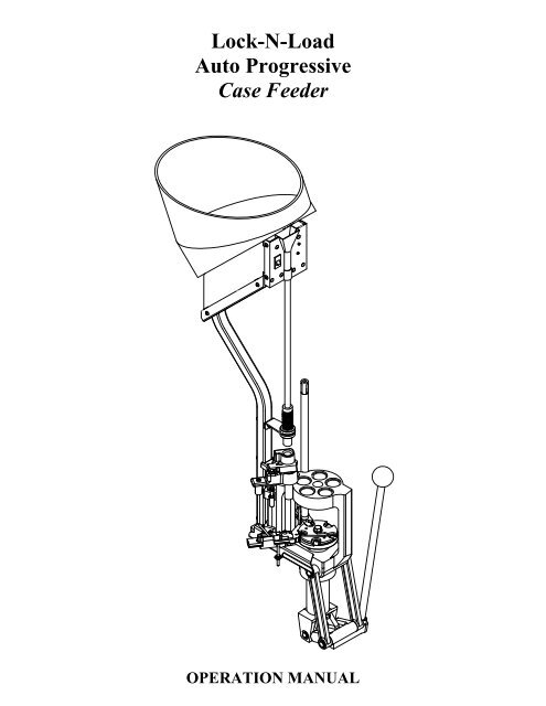
<strong>Lock</strong>-N-<strong>Load</strong><br />
<strong>Auto</strong> <strong>Progressive</strong><br />
<strong>Case</strong> <strong>Feeder</strong><br />
OPERATION MANUAL
Table of Contents<br />
Steps Page<br />
Overview.....................................................................................................................4<br />
List of required hand tools ..........................................................................................4<br />
1: Mounting the <strong>Lock</strong>-N-<strong>Load</strong> <strong>Auto</strong> <strong>Progressive</strong> with <strong>Case</strong> <strong>Feeder</strong> ........................5<br />
2: Changing the sub-plate ..........................................................................................6<br />
3: Assemble the square tubing brackets.....................................................................8<br />
4: Placing the square tubing brackets onto the square tubing....................................9<br />
5: Assemble the square tubing and brackets to the frame of the AP Press................10<br />
6: Assemble the square tubing to the frame of the AP Press.....................................11<br />
7: Adding the case slide onto the sub-plate ...............................................................12<br />
8: Inserting the cam wire into the assembly...............................................................14<br />
9: <strong>Case</strong> escapement bracket assembly .......................................................................15<br />
10: Mounting the Feed tube bracket to the square tubing..........................................16<br />
11: Determine which caliber you are going to be loading.........................................17<br />
12: Installing the V-block to the case slide................................................................18<br />
13: Changing and installing the shell plate.................................................................19<br />
14: Set the timing of the cam wire.............................................................................20<br />
15: Assembling the feed tube end and pivot..............................................................22<br />
16: Placing the feed tube end on the assembly ..........................................................23<br />
17: Selecting the case feed plate for your application ...............................................24<br />
18: Adjusting the push rod.........................................................................................26<br />
Single case operation ..................................................................................................26<br />
Fail-safe mechanism ...................................................................................................26<br />
Maintenance of the <strong>Lock</strong>-N-<strong>Load</strong> A/P <strong>Case</strong> <strong>Feeder</strong>...................................................27<br />
Trouble free operation.................................................................................................27<br />
List of Illustrations<br />
Figures<br />
1. AP with main bracket.............................................................................................5<br />
2. Spent primer tube dismantle/assembly ..................................................................6<br />
3. Square tubing brackets with set screws .................................................................8<br />
4. Square tubing brackets with square tubing ............................................................9<br />
5. Square tubing brackets to AP Frame .....................................................................10<br />
6. Square tubing to AP Frame....................................................................................11<br />
7a. <strong>Case</strong> slide assembly...............................................................................................12<br />
7b. <strong>Case</strong> slide and sub-plate assembly........................................................................12<br />
8. Assembly of cam wire ...........................................................................................14<br />
9. Assembling case escapement bracket on square tubing .......................................15<br />
10. Feed tube mounting bracket to square tubing......................................................16<br />
11. V-block selection .................................................................................................17<br />
12. Inserting the V-block ...........................................................................................18<br />
13. Adjusting the V-block..........................................................................................20<br />
14. Feeding a case......................................................................................................20<br />
15. Cam rod adjustment .............................................................................................21<br />
16. Pivot assembly .....................................................................................................22<br />
17a. Setting the feed tube end (most cases) ...............................................................23<br />
17b. Setting the feed tube end (357 Mag., etc.) ..........................................................23<br />
18. <strong>Case</strong> feed bowl door adjustment..........................................................................25<br />
19. Push rod adjustment.............................................................................................26<br />
2
Table of Contents Cont.<br />
Charts<br />
1. Caliber change over chart ......................................................................................17<br />
2. Shell plate selection chart ......................................................................................19<br />
3. <strong>Case</strong> feed wheel selection chart .............................................................................24<br />
4. Trouble free operation............................................................................................27<br />
5. Bill of Materials .....................................................................................................28<br />
6. Exploded view .......................................................................................................29<br />
3
Hornady<br />
<strong>Lock</strong>-N-<strong>Load</strong> <strong>Auto</strong> <strong>Progressive</strong><br />
Your new AP <strong>Case</strong> <strong>Feeder</strong> has been packaged to insure minimal shifting and damage<br />
during transportation.<br />
Remove all the parts from the shipping box and spread them out over a large flat surface.<br />
Refer to the parts list on pages 28-29 to make sure all necessary parts are identified.<br />
The manual provides step-by-step instructions and suggestions that make set-up and<br />
operation easy and understandable.<br />
• Remember, everything is designed and machined to fit easily together without<br />
modification. If you find that it is necessary to force parts together, stop and<br />
check the instructions and illustrations we have provided.<br />
• 3/8” wrench<br />
• 7/16” wrench<br />
• 9/16” wrench<br />
• 1/8” Allen wrench<br />
• 5/32” Allen wrench<br />
• 3/16” Allen wrench<br />
• Pliers or vise grips<br />
• Small hammer<br />
List of needed hand tools:<br />
4
Step 1: Mounting the <strong>Lock</strong>-N-<strong>Load</strong> <strong>Auto</strong> <strong>Progressive</strong> with <strong>Case</strong> <strong>Feeder</strong><br />
Figure 1: AP with main bracket.<br />
• Your work area should be well lit and have plenty of room for your reloading<br />
accessories. Your Hornady <strong>Lock</strong>-N-<strong>Load</strong> AP should be mounted securely to the<br />
edge of a solid level bench approximately 2 ¼” from the center of holes to the front<br />
edge of the table when using the optional case feeder.<br />
• While facing the bench and using the Main Bracket (#42) for a pattern, mark and<br />
drill the mounting holes. Mount the press using (2) 5/16” bolts that are long enough<br />
to secure the press to the bench with plenty of clearance for the nuts. (Due to<br />
variations of benches we have chosen to not provide these items) We also<br />
recommend using 5/16” flat washers at both ends of the bolts with lock washers on<br />
the bottom side of the table. Washers are required on the two mounting bolts when<br />
using the case feeder system.<br />
• Place the Main Bracket (#42) on the bench and verify that the mounting holes line<br />
up with the holes. Place the Bracket on the underside of the Press Frame. Place one<br />
of the 5/16 bolts through the mounting hole from the top. Place the press and bracket<br />
on the bench, and run the bolt down through the appropriate hole and secure it to the<br />
bench with a nut and washer assembly (finger tight is good for now). Align the<br />
second hole, and using the second bolt, secure it to the bench. Operate the press; to<br />
make sure that the bench does not interfere with it’s operation. If everything is<br />
functioning proper, tighten the nuts on the bolts to finish securing the press and<br />
mounting plate to the bench.<br />
See Figure 1 for details.<br />
5
Step 2: Changing the Sub-Plate.<br />
(This step is necessary only if you are installing the case feeder to an existing<br />
press, with a serial number lower than 07000.) The new Sub-Plate (Part<br />
Number 398309) is sold separately. The new priming system (Part Number<br />
095210) is also sold separately for presses with serial # prior to 07000.<br />
• Raise the Eject Wire (#46) to move it out of the way.<br />
• Use a 9/16” end wrench to remove the bolt holding down the shell plate and<br />
remove the shell plate.<br />
• Remove the case retainer spring.<br />
• Remove the primer feed assembly.<br />
• Unhook the extension spring from the primer slide and remove it from the Sub-<br />
Plate (#44).<br />
• Remove the primer slide from the Sub-Plate.<br />
Figure 2: Spent primer tubes dismantle / assembly.<br />
• Place the spent primer assembly tool in the bottom of the spent primer tube. Take<br />
a pair of pliers or vise grips and clamp onto the spent primer tube approximately<br />
¼” from the end and tap the pliers with a hammer to remove the spent primer<br />
tube. Be careful not to lose the Counter Balance spring.<br />
See Figure 2 for more details.<br />
• Raise the ram to the top of the stroke and “Block” it into place<br />
6
• The Ram can be blocked into place by inserting the handle of a medium sized<br />
screw driver between the “Toggle” and the “Yoke” near the pawls. Be careful not<br />
to put extreme pressure on the Index wheel as you may damage it.<br />
• Use a 5/32” Allen wrench to remove the two screws that secure the Sub-Plate<br />
onto the ram.<br />
• Remove the “Block” and lower the ram and remove the “Sub-Plate”.<br />
• Install the new “Sub-Plate”, raise the ram and replace the “Block” before<br />
installing the screws and tightening them very tight. (Be careful not to strip the<br />
socket or damage the threads.)<br />
• Once again, remove the “Block”, lower the ram and replace all parts in the reverse<br />
order that you removed them.<br />
The instructions thru Step 5 are for a <strong>Lock</strong>-N-<strong>Load</strong> <strong>Auto</strong> <strong>Progressive</strong> Frame without<br />
the new machined bosses on the frame, serial # 07279 and later.<br />
7
Step 3: Assemble the square tubing brackets.<br />
See Figure 3 for more details.<br />
Figure 3: Square tubing bracket with set screws.<br />
• Lay the two Brackets (#45) in front of you along with two 5/16-18 x 5/8 Cup Set<br />
Screws (#35) and two 5/16-18 x 5/8 Cone Point Set Screws (#36).<br />
• Place one Cone Point Set Screw (#36) into the side of the Square Tubing Bracket<br />
(#45) until the point is just flush with the inside surface of the Bracket.<br />
• Place one (#35) Cup Set Screw in the back of the Bracket until the cup point is<br />
just flush with the inside of the Bracket.<br />
• Repeat these steps for the second Bracket.<br />
8
Step 4: Mounting the square tubing brackets on to the square tubing.<br />
See Figure 4 for more details.<br />
Figure 4: Square tubing brackets with square tubing.<br />
• Place the ¼” Flat Washers (#48) on the ¼-20 x 1 ¼” Socket Head Cap Screw<br />
(SHCS) (#47).<br />
• Place one SHCS thru the Square Tubing (#49) and into one of the Square Tubing<br />
Brackets (#45) as shown and tighten finger tight.<br />
• Repeat for the second Bracket.<br />
¼-20 1 ¼” Cap Screw (Full Size)<br />
9
Step 5: Assemble the square tubing and brackets to the frame of the AP Press.<br />
(This step is a preliminary adjustment and will be completed later in the assembly.)<br />
See Figure 5 for more details.<br />
Figure 5: Square tubing brackets to the frame.<br />
• While standing to the left side of the press, (your left), hook the v-section of<br />
bracket to the rib on the corner of the frame.<br />
• Rotate the square tubing with the brackets counter clockwise (CCW) around<br />
the corner of the press. Make sure that the tube rests on the tab of the<br />
mounting bracket.<br />
• Tighten the two (Cone Point) set screws (#36) until about half of the angled<br />
point is past the corner of the rib on the press.<br />
• Tighten the two (Cup Point) set screws (#35) until the square tubing assembly<br />
is secure.<br />
• Finish by tightening the screws (#47) on the Square tubing and bracket<br />
assembly.<br />
• The back of the square tubing should be parallel to the back edge of the frame.<br />
If it is not, you will need to readjust it using the set screws.<br />
• The assembly can be rotated clockwise by loosening the Cone Point screws<br />
(#36) and tightening the Cup Points (#35), and visa versa to rotate it Counter<br />
Clockwise. Complete the installation by tightening the Cup Point Set Screws<br />
(#35).<br />
10
Step 6: Assemble the square tubing to the frame of the AP Press.<br />
(For serial numbers beyond 07279.)<br />
Figure 6: Square tubing to the frame.<br />
• Place the ¼” Flat Washers (#48) on the ¼-20 x 1 ¼” Socket Head Cap Screw<br />
(SHCS) (#47).<br />
• Place one SHCS thru the Square Tubing (#49) and thread into the Frame.<br />
• Repeat for the second Bracket.<br />
• Tighten both screws down using a 3/16” Allen wrench.<br />
¼-20 1 ¼” Cap Screw (Full Size)<br />
11
Step 7: Adding the case slide on to the sub-plate.<br />
See Figure 7b for more details.<br />
Figure 7a: <strong>Case</strong> slide assembly.<br />
• While holding the case slide (#38) upside down in one hand, pull the<br />
cardboard packaging rearward till the front edge bi-sects the foot at the front<br />
of the slide.<br />
See Figure 7a for more details.<br />
Figure 7b: <strong>Case</strong> slide and sub-plate assembly.<br />
• Turn the <strong>Case</strong> Slide (#38) right side up and start the slide onto the rail of the<br />
sub-plate. While holding the end of the cardboard, push the slide onto the rail.<br />
You may need to push up on the bottom of the cardboard while you are<br />
pushing it on the sub-plate.<br />
12
• If now or anytime in the future the guide and spring come out of the slide,<br />
they can be assembled by placing the spring in the relief of the slide and<br />
hooking the relief of the guide onto the end of the spring. Slide the guide<br />
forward and compress the spring until the guide fits into the pocket. You may<br />
need to hold the “guide and spring” into the Slide with your finger as you<br />
slide the assembly back onto the “Sub-Plate.”<br />
13
Step 8: Inserting the cam wire into the assembly.<br />
See figure 8 for more details.<br />
Figure 8: Assembly of cam wire.<br />
• Raise the ram to the top of the stroke.<br />
• Screw one #10-32 Hex Nut (#41) on to the Cam Wire (#43) approximately 1”<br />
from the end.<br />
• Place one of the #10 Flat Washers (#67) onto the Cam Wire (#43).<br />
• From the bottom of the Sub-Plate (#44), slide the non threaded end of the<br />
Cam Wire (#43) through the slot of the Sub-Plate (#44) and through the <strong>Case</strong><br />
Slide (#38).<br />
• Insert the threaded end of the Cam Wire through the hole of the tab on the<br />
Main Bracket (#42).<br />
• Insert the other Flat Washer (#67) and Hex Nut (#41) onto the bottom of the<br />
Cam Wire (#43) and tighten finger tight.<br />
• Lower the ram.<br />
14
Step 9: <strong>Case</strong> escapement bracket assembly.<br />
See Figure 9 for details.<br />
Figure 9: Assembling <strong>Case</strong> escapement bracket on square tubing.<br />
• Put a ¼” Flat Washer (#48) on the ¼-20 X 1 ½” Cap Screw (#70).<br />
• Slide the Cap Screw (#70) thru the Square Tubing and thread the Hex Nut (#26),<br />
on approximately the length of the nut.<br />
• Slip the <strong>Case</strong> Escapement Body (#29) over the Cap Screw so the Hex Nut (#26) is<br />
in the slot on the back of the <strong>Case</strong> Escapement Body. (#29)<br />
• Slip the Cam Wire (#43) into the Cam Wire Support (#31).<br />
• Tighten the Cap Screw (#70) while holding the Bracket level with the top of the<br />
frame.<br />
¼-20 x 1 ½” Cap Screw (Full Size)<br />
15
Step 10: Feed Tube Mounting Bracket to the square tubing.<br />
See Figure 10 for more details.<br />
Figure 10: Feed Tube Mounting Bracket with square tubing.<br />
• Put a ¼” Flat Washer (#48) on a ¼-20 X 1 ½” Cap Screw (#70).<br />
• Slide the Cap Screw (#70) thru the Square Tubing and place the Feed Tube<br />
Mounting Bracket (#16) over the Cap Screw (#70), then insert the Hex Nut (#26)<br />
on the Cap Screw and tighten. Make sure that the top of the Feed Tube Mounting<br />
Bracket (#16) is level. Check with a small level if you are unsure.<br />
¼-20 x 1 ½” Cap Screw (Full Size)<br />
16
Step 11: Determine which cartridge case you are going to be loading.<br />
Chart 1 below shows what parts are needed for different size of cases.<br />
<strong>Case</strong>s Item #'s Required Pg. 28 & 29 Notes<br />
Small Pistol (9mm, 40 S&W, etc..) 66,14,50,52,53 <strong>Case</strong>s smaller than .43" maximum diameters<br />
Large Pistol (.357 Mag., .44 Mag, etc..) 13,15,22 <strong>Case</strong>s larger than .43" maximum diameters<br />
Small Rifle (.223, 22 Hornet) 66,14,50,18,51,52,53 <strong>Case</strong>s smaller than .43" maximum diameters<br />
Large Rifle (243 Win., 45-70 Govt., etc..) 13,15,18,22 <strong>Case</strong>s larger than .43" maximum diameters<br />
Chart 1: Cartridge <strong>Case</strong> change over chart.<br />
If you find that some cases such as the 40 S&W are tight in the Feed Tube –Small (#14),<br />
you may need to use the part of both the large and small feed tubes. For example, 40<br />
S&W could use item numbers 13, 15, 19 and 53.<br />
See figure 11 for more details on selecting the V-Block.<br />
CASES DIAMETERS "X" V-BLOCK # V-BLOCKS P/N:<br />
22 Hornet .27-.30 1 398292<br />
9mm, .223 .37-.39 2 398293<br />
44 Mag. .35-.38 3 398294<br />
30-06 .42-.47 4 398295<br />
458 Win. Mag. .46-.58 5 398296<br />
10mm .41-.44 6 398297<br />
Figure 11: V-Block selection chart.<br />
17
Step 12: Installing the V-Block onto the case slide.<br />
Figure 12: Inserting the V-block.<br />
• With the ram at the bottom of the stroke (idle position), set the V-Block (item<br />
#60-#65) onto the <strong>Case</strong> Slide (#38).<br />
• Place the #10-24 X 1/2 Cap Screw (#59) through the hole of the V-Block and<br />
screw it into the <strong>Case</strong> Slide. Before you tighten the Cap Screw, push the V-Block<br />
back into the <strong>Case</strong> Slide and snug the Cap Screw with your fingers.<br />
18
Step 13: Determine which shell plate is required for your application.<br />
See Chart 2 below to help with this selection.<br />
SHELL PLATE NO. 1 358 Win. 7MM Merrill 38/357/357 Max. SHELL PLATE NO. 14 204 Ruger SHELL PLATE NO. 36<br />
Item No. 392601 9.3x57 Item No. 392614 Item No. 392636<br />
5.6x57 9.3x62 SHELL PLATE NO. 5 SHELL PLATE NO. 7 33 Win. SHELL PLATE NO. 22 32 S&W Long/Short/H&R<br />
22/250 44 <strong>Auto</strong> Mag. Item No. 392605 Item No. 392607 338/378 Wby. Item No. 392622 300 Win. Short Mag<br />
240 Wby. 45 ACP/WM 257 Wby. 6.5 Rem. Mag. 218 Bee 460 Wby. 30 M1 Carbine<br />
243 Win. 260 Rem. 264 Win. Mag. 25/20 Win. 45/70 Govt. 32 ACP SHELL PLATE NO. 40<br />
244/6MM 270 Wby. 32/20 Win. 416 Wby. Item No. 392640<br />
6MM int. SHELL PLATE NO. 2 7MM Rem. Mag. 480/475 Linebaugh SHELL PLATE NO. 26 50 AE<br />
6MM/284 Item No. 392602 7MM Wby. SHELL PLATE NO. 8 Item No. 392626<br />
6MM Br 219 Zipper 300 H&H Item No. 392608 SHELL PLATE NO. 15 35 Remington SHELL PLATE NO. 41<br />
250 Sav. 5.6x52R 300 Win. Mag. 30 Luger Item No. 392615 Item No. 392641<br />
25/06 22 Sav. HP 300 Wby. 9MM Luger 376 Steyr SHELL PLATE NO. 29 45 Schofeild<br />
257 Rbts. 25/35 Win. 300 Re. UI. Mag. 9x18 Makarov Item No. 392629<br />
25/284 30/30 Win. 308 Norma Mag. 38 Super <strong>Auto</strong> SHELL PLATE NO. 16 41 Mag. SHELL PLATE NO. 43<br />
6.5/06 30 Herrett 8MM Rem. Mag. 9x23 Item No. 392616 Item No. 392643<br />
6.5 x 57 32 Win. Spl. 338 Win. Mag. 17 Rem. SHELL PLATE NO. 30 338 Lapua<br />
270 Win. 8.15x46 R 340 Wby. SHELL PLATE NO. 9 17/222 Item No. 392630<br />
7x57 (7MM mau.) 357 Herrett 350 Rem. Mag. Item No. 392609 17/223 6.5x68 SHELL PLATE NO. 44<br />
7MM/08 375 Win. 358 Norma Mag. 38/40 Win. 221 Rem. 8x68 S Item No. 392644<br />
7MM Rem. BR 7x30 Waters 375 H&H 44/40 Win. 222 Rem. 7.5 Swiss 500 S&W<br />
7x64 32/40 416 Rem. Mag. 222 Rem. Mag. 357/44 B&D<br />
7MM Exp/280 458 Win. SHELL PLATE NO. 10 5.6x50 Mag. 44 Spl./44 Mag.<br />
284 Win. SHELL PLATE NO. 3 450 Marlin Item No. 392610 223 Rem.<br />
300 Sav. Item No. 392603 10MM <strong>Auto</strong> 6MM/223 SHELL PLATE NO. 32<br />
308 Win. 22 Hornet SHELL PLATE NO. 6 40 S&W 6x47 Rem. Item No. 392632<br />
30/06 22-K Hornet Item No. 392606 6.5MM TCU 45 Long colt<br />
7.7 Jap. 22 PPC SHELL PLATE NO. 11 7MM TCU 454 Casull<br />
8MM Mau. SHELL PLATE NO. 4 22 RCFM-Jet Item No. 392611 7MM/223 Ingram<br />
8MM /06 Item No. 392304 256 Win. 303 British 7x47 Helm SHELL PLATE NO. 35<br />
8x60 S 220 Swift 6MM PPC 30/40 Krag 380 <strong>Auto</strong> Item No. 392635<br />
35 Whelen 225 Winchester 7.62x39 6MM TCU 6x61 S&H<br />
Chart 2: Shell Plate selection chart.<br />
Changing and installing the shell plate.<br />
(Refer to the operations manual for the AP Press.)<br />
19
Step 14: Setting the timing of the cam wire.<br />
Figure 13: Adjusting the V-block.<br />
• Place a case of the proper size into the shell plate and manually push the <strong>Case</strong><br />
Slide (#38) and V-Block into the case. Loosen the Cap Screw (#59) and<br />
continue to push the <strong>Case</strong> Slide into the case. Tighten the Cap Screw (#59)<br />
with a 3/16” allen wrench.<br />
See Figure 13 for more details.<br />
Figure 14: Feeding a case.<br />
• Raise the ram until the shell plate rotates and place a case (of the proper size)<br />
in-front of the V-Block on the Sub-Plate. Lower the ram so the <strong>Case</strong> Slide<br />
will advance the case into the shell plate.<br />
20
See Figure 13 for more details.<br />
Figure 15: Cam rod adjustment.<br />
If the “Cam Wire” is too high, it will:<br />
1. Not allow the “Shell Plate” to advance. Loosen the upper nut several turns and<br />
pull the wire down.<br />
2. The case will hit the “Shell Plate” before it rotates. Again, loosen the upper nut<br />
and move the wire down, but do this in small increments, as you are close.<br />
If the wire is to low, it will:<br />
1. Not advance the case into the shell plate. Loosen the Lower nut and tighten the<br />
upper one to move the cam down.<br />
Once the timing is correct, snug both nuts to the bracket and make sure the cam is<br />
centered in the Slide. This can be adjusted manually by rotating it around the threaded<br />
end a small amount. Tighten the nuts to complete the timing process. This timing setting<br />
is adequate for all cartridges, and it should not be necessary to make future changes.<br />
21
Step 15: Assembling the feed tube end and pivot.<br />
See Figure 15 for more details.<br />
Figure 16: Pivot Assembly.<br />
• If the maximum case diameter is larger than .43 you will need to use the large<br />
tube (#22). If it is smaller, you will need the small tube (#53). Place the correct<br />
one into the pivot block (#29).<br />
• Place the torsion spring (#23) into the slot in the pivot block (#29), leaving the<br />
long leg on the top side. The spring will only fit one way.<br />
• Set the pivot (#19) on top of the pivot block. Make sure you line up the under cut<br />
on the cam with the torsion spring. The leg of the torsion spring will fit into the<br />
slot on the cam.<br />
• When this fits together the pivot should fit on top of the pivot block. The dowel<br />
pin in the cam will fit into the curved slot on the cam block.<br />
• Then insert the shoulder bolt (#20) into the pivot and into the pivot block and<br />
tighten with an allen wrench.<br />
• Actuate the pivot by hand to make sure it will rotate properly.<br />
• For small rifle cases place the pivot adapter bushing (#51) into the hole of the<br />
pivot adapter. See pg. 25 for more details.<br />
• Place the pivot adapter (#18) on top of the pivot for rifle cases (See pg. 25 for<br />
more details).<br />
22
Step 16: Placing the Feed tube end on the assembly.<br />
17a. 17b.<br />
Figure 17: Setting the Feed tube end.<br />
• Select the tube for your application (#15 or #50), see pages 25 and 26.<br />
• Screw one lock ring on the tube.<br />
• Place it thru the hole on the feed tube mounting bracket. Adjust the height of the<br />
tube to have approximately 1/16” below the bottom of the tube to the case mouth.<br />
(See Figure 16a for more details.) With some cases such as the 357 Mag. it may<br />
be necessary to adjust the tube to where the case mouth sits up inside of the tube<br />
approximately 3/16”. (See Figure 16b for more details.) These are both starting<br />
points, and for your particular case, it may need to be adjusted a little differently.<br />
(Long skinny cases, which are shorter than 1.50” long will not work with the<br />
Pivot Adapter (#18). They may need to be supported at the mouth of the case by<br />
the Feed Tubes (#15 or #50). This will allow the case to feed down the Drop<br />
Tubes (#22 or #53) with out falling over and causing double or triple feeds.<br />
• Screw on the other lock ring.<br />
• Select the proper “Feed Tube” (#13 or #14) and insert it in the top of the “Feed<br />
Tube End” (#15 or #50). If you select The Small Feed Tube (#14), you will have<br />
to use the Plastic Feed Tube Small Bushing (#66), see pages 25 and 26.<br />
(When feeding some cases (such as the 357 Mag.) you may notice that the base of<br />
the case will not fall into the hole of the pivot every-time. The base will ride on the<br />
radius of the pivot hole. You can operate the press with the cases doing this and<br />
when the push rod (#24) starts to rotate the cam, the case will fall into the hole).<br />
23
Small Pistol<br />
<strong>Case</strong> Feed<br />
Wheel<br />
Step 17: Selecting the case feed wheel for your application.<br />
See Chart 3 for more details.<br />
Large Pistol<br />
<strong>Case</strong> Feed<br />
Wheel<br />
Small Rifle <strong>Case</strong><br />
Feed Wheel<br />
Large Rifle <strong>Case</strong> Feed<br />
Wheel Large Rifle Cont. Large Rifle Cont. Large Rifle Cont.<br />
P/N: 095310 P/N: 095312 P/N: 095314 P/N: 095316<br />
9mm 10mm <strong>Auto</strong> 7.62 X 39 6mm Rem. .284 Win. .356 Win. .300 Rem. Saum<br />
9 X 21 .357 Mag. .17 Rem. 6.5mm Rem. Mag. .30 Rem. .358 Win. .300 WSM<br />
.38 Super .357 Rem. Max. .218 Bee 6.5 X 55 Swedish Mauser .30-06 Springfild .375 H&H Mag. .300 Dakota<br />
9 X 18 Makarov .38 Long Colt .222 Rem./Rem Mag. 7mm Mauser (7 X 57) .30-30 Win. .375 Win. .300 Rem. Ultra Mag.<br />
9mm Win Mag .38 Short Colt .223 Rem (5.56mm) 7mm Rem. Mag. .30-40 Krag .38-55 Win. .338 Rem. Ultra Mag.<br />
.30 Luger .38 S&W .30 Carbine 7mm WBY Mag. .300 H&H Mag. .416 Rem. Mag. .340 WBY Mag.<br />
32 ACP .38 Spl. .32-20 Win. 7mm-08 Rem. .300 Savage .416 Rigby .378 WBY Mag.<br />
.32 H&R Mag .41 Rem. Mag. .351 Win Self <strong>Load</strong>ing 7-30 Waters .300 WBY Mag. .444 Marlin .404 Jeffery<br />
.32 Long Colt .44 Spl/Mag. .25-20 Win. 8mm Mauser (8 X 57) .300 Win. Mag. .45-70 Govt. .460 WBY Mag.<br />
.32 Short Colt .45 ACP 8mm Rem. Mag. .303 British .458 Win. Mag. 500 S&W<br />
.32 S&W .45 <strong>Auto</strong> Rim. .22-250 .303 Savage .458 Lott<br />
.32 S&W Long .45 Colt .220 Swift .307 Win. .450 Marlin<br />
.380 <strong>Auto</strong> .45 Win. Mag. .225 Win. .308 Win. .376 Steyr<br />
.22 Hornet .454 Casull .243 Win. .32 Rem. .405 Win.<br />
40 S & W 9 X 25 .25-06 .32 Win. Spl. .240 WBY Mag.<br />
.22 Rem. Jet .25-35 Win. .32-40 Win. .257 WBY Mag.<br />
.256 Win. Mag. .250 Savage .338 Win. Mag. .270 WBY Mag.<br />
.475 Linebaugh .257 Roberts .348 Win. .270 WSM<br />
.480 Ruger .264 Win. Mag. .35 Rem. 7mm Rem Saum<br />
.38-40 Win. .270 Win. .35 Whelen 7mm STW<br />
.44-40 Win. .280 Rem. .350 Rem. 7mm Rem. Ultra Mag.<br />
Chart 3: <strong>Case</strong> feed wheel selection chart.<br />
24
Figure 18: <strong>Case</strong> feed bowl door adjustment.<br />
• Select the <strong>Case</strong> Feed Plate (item #54-57) for your application and place it on the<br />
motor shaft. The clutch on the plate will slip onto the motor shaft fitting flush to<br />
the bottom of the <strong>Case</strong> Feed Bowl (#1).<br />
• Place the O-Ring onto the Feed Tube Large (#13) approximately 2” from one end.<br />
The O-Ring when pushed down on top of the Feed Tube End (#15) will hold the<br />
feed tube into the funnel on the case feed bowl.<br />
• Set the <strong>Case</strong> Feed Bowl (#1) on top of the Square Tubing (#49) while inserting<br />
the Feed Tube (#13 or #14) into the <strong>Case</strong> Feed Funnel Assembly (#8) and plug it<br />
into a power outlet.<br />
• If you are loading rifle cartridges you will need to adjust the <strong>Case</strong> Feed Door<br />
(#37).<br />
• Loosen the ¼” Button Head Cap Screw (#68) and slide the <strong>Case</strong> Feed Door<br />
Adjustment (#37) so the opening is approximately ¾ the length of the case. This<br />
is a preliminary setting. Place a hand-full of cases into the <strong>Case</strong> Feed Bowl (#1).<br />
• Turn the motor on and observe to see if the cases will fall base first. If they do<br />
not, readjust the <strong>Case</strong> Feed Bowl Door Adjustment (#37) until they do with out<br />
hanging up or getting caught.<br />
• Re-tighten the ¼” Button Head Cap Screw (#68).<br />
• To load pistol cases, completely open the <strong>Case</strong> Feed Door Adjustment.<br />
See figure 17 for more details.<br />
25
Step 18: Adjusting the push rod.<br />
Figure 19: Push Rod adjustment.<br />
• Screw the Push Rod Nut (#33) and the Push Rod Lower (#34) onto the Push Rod<br />
(#24) until the Push Rod Lower (#34) bottoms out on the thread.<br />
• Place a case in the hole of the Pivot (#19) and the Escapement Height adjuster<br />
(#18) (if required).<br />
• Raise the ram to the top of the stroke slowly, so the <strong>Case</strong> Slide (#38) will actuate<br />
the Push Rod (#24) and Pivot (#19). The Pivot (#19) should rotate far enough to<br />
drop a case down the Feed tube (#13-14). If it does not, lower the ram just far<br />
enough to take the pressure off of the Push rod (#24). Screw the Push Rod Lower<br />
(#34) down a couple of turns and retry. When the Pivot (#19) is dropping a case<br />
thru the Feed Tube, screw the Push Rod Nut (#33) down on top of the Push Rod<br />
Lower (#34) and tighten with your fingers.<br />
• If the case is falling on top of the V-Block, refer to step Step 5.<br />
Single case operation<br />
(To feed cases singly without using the case feeder.)<br />
• Remove the Push Rod Lower (#34).<br />
This will allow the press to be cycled without dropping cases.<br />
Fail-safe mechanism<br />
The Cam Wire (#43) has a fail-safe mechanism at its top (Cam Wire Support #31). The<br />
Cam Wire Support (#31) holds the Cam Wire (#43) in place. If a malfunction occurs, the<br />
Cam Wire (#43) is able to snap out of the support to prevent damage to the Cam Wire.<br />
26
Maintenance of the <strong>Lock</strong>-N-<strong>Load</strong> A/P <strong>Case</strong> <strong>Feeder</strong><br />
As with all equipment, proper and routine maintenance will provide smooth operation<br />
and a longer life for your reloading press and <strong>Case</strong> <strong>Feeder</strong>. At the end of each reloading<br />
session, wipe off all spilled powder, any dirt, etc., from the press. Check all moving parts<br />
for dirt or spilled powder and remove with a clean rag.<br />
Tips for trouble-Free operation<br />
Problems Solutions Step<br />
<strong>Case</strong>s are hitting the back corner<br />
of the shell plate when feeding<br />
into the shell plate.<br />
Slow timing down or Readjust<br />
V-Block location 13<br />
<strong>Case</strong>s are not feeding into the Speed timing up or<br />
shell plate far enough<br />
Using the wrong V-Block 13<br />
<strong>Case</strong>s are tipping when going into Re-adjust V-Block<br />
the shellplate<br />
location 13<br />
<strong>Case</strong>s are falling on top of the V- Re-adjust the Bracket,<br />
Block<br />
Drop tube is tight against the AP<br />
Square Tubing 5<br />
Frame; will not allow changing of Re-adjust the Bracket,<br />
tubes<br />
Square Tubing 5<br />
<strong>Case</strong>s are falling mouth first out Close the door<br />
of the bowl<br />
adjustment 16<br />
<strong>Case</strong>s are getting caught in the Open the door<br />
open hole on the bowl<br />
The shell plate is hitting the V-<br />
adjustment 16<br />
Block when it's rotating Lower the Cam Wire 13<br />
Chart 4: Trouble free operation.<br />
27
Bill of Materials<br />
Production Part<br />
Production Part<br />
Item No. Number Qty. Description Item No. Number Qty. Description<br />
1 398327 1 CASE FEED BOWL 37 398285 1 CASE FEED DOOR ADJUSTMENT<br />
2 398313 4 10-32 x 3/4 FHSCS 38 398291 1 CASE SLIDE<br />
3 398374 8 10-24 "U" Nut 39 398307 1 CASE SLIDE ROD GUIDE<br />
4 398415 8 #8 x 1/2 SHEET METAL SCREW PAN HEAD PHILIPS 40 398308 1 CASE SLIDE ROD GUIDE SPRING<br />
5 398326 1 MOTOR HOUSING 41 392011 2 10-32 HEX HEAD NUT<br />
6 398375 2 4-40 HEX HEAD LOCK NUT 42 398289 1 MAIN BRACKET<br />
7 398333 1 MICRO SWITCH 43 398299 1 CAM WIRE<br />
8 398369 1 CASE FEED FUNNEL ASSEMBLY 44 398309R 1 SUB-PLATE (ON PRESS OR WITH RETROFIT KIT)<br />
9 398376 1 4-40 X 5/8 BHSCS 45 398287 2 BRACKET, SQ. TUBING<br />
10 398332 2 ROCKER SWITCH 46 398345 1 EJECT WIRE (ON SUB-PLATE #44)<br />
11 398331 1 MOTOR 47 398312 2 1/4-20 X 1.25 SHCS<br />
12 398328 1 MOTOR COVER 48 390128 4 1/4 FLAT WASHER ZINC PLATED<br />
13 398320 1 FEED TUBE - LARGE 49 398284 1 CASE FEED STAND<br />
14 398321 1 FEED TUBE - SMALL 50 398304 1 FEED TUBE END - SMALL<br />
15 398303 1 FEED TUBE END - LARGE 51 398300 1 PIVOT ADAPTER BUSHING<br />
16 398286 1 FEED TUBE MOUNTING BRACKET 52 398301 1 PIVOT BUSHING<br />
17 396440 2 LOCK RING 53 398306 1 DROP TUBE - SMALL<br />
18 398298 1 PIVOT ADAPTER 54* O95310 CASE FEED PLATE- SMALL PISTOL<br />
19 398290 1 PIVOT 55* O95312 CASE FEED PLATE - LARGE PISTOL<br />
20 398310 1 1/4-3/4 SHOULDER BOLT 56* O95314 CASE FEED PLATE - SMALL RIFLE<br />
21 398311 1 3/0 X 3/4 TAPER PIN 57* O95316 CASE FEED PLATE - LARGE RIFEL<br />
22 398305 1 DROP TUBE - LARGE 58 O59100 AP PRESS<br />
23 398288 1 SPRING, TORSION 59 392338 1 10-24 X 1/2 SHCS<br />
24 398317 1 PUSH ROD 60 398293 1 V-BLOCK #1<br />
25 398371 1 PUSH ROD TIP 61 398297 1 V-BLOCK #2<br />
26 390178 2 1/4-20 HEX HEAD NUT 62 398294 1 V-BLOCK #3<br />
27 398349 1 PUSH ROD BUSHING 63 398292 1 V-BLOCK #4<br />
28 398364 1 10 X 1/2 SHEET METAL SCREW PAN HEAD PHILIPS 64 398295 1 V-BLOCK #5<br />
29 398344 1 PIVOT BODY 65 398296 1 V-BLOCK #6<br />
30 398363 1 PUSH ROD SPRING 66 398324 1 PLASTIC FEED TUBE SMALL BUSHING<br />
31 398343 1 CAM WIRE SUPPORT 67 390651 2 3/16" FLAT WASHER SAE<br />
32 398425 1 E CLIP 1/4 68 390410 1 10-24 x 1/4 BHSCS<br />
33 398373 1 PUSH ROD NUT 69 398370 1 CASE FEED BOWL BUSHING<br />
34 398372 1 PUSH ROD LOWER 70 398388 2 1/4-20 X 1.50 SHCS<br />
35 398314 2 5/16 -18 X 5/8 SET SCREW CUP 71 398416 1 O-RING 7/8 OD, 11/16 ID<br />
36 398315 2 5/16 -18 X 5/8 SET SCREW CONE POINT (45 DEG.) 72 398550 6 RIVET POLY BLACK<br />
Chart 5: Bill of Materials.<br />
(“*” Sold Separately) (“Italics” Pre Assembled)<br />
28
(780308, Original, 09/02/04)<br />
30