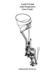
HORNADY 366 AUTO OPERATION MANUAL - Hornady.com
HORNADY 366 AUTO OPERATION MANUAL - Hornady.com
HORNADY 366 AUTO OPERATION MANUAL - Hornady.com

Create successful ePaper yourself
Turn your PDF publications into a flip-book with our unique Google optimized e-Paper software.
<strong>HORNADY</strong><br />
<strong>366</strong> <strong>AUTO</strong><br />
<strong>AUTO</strong>MATIC SHOTSHELL RELOADER<br />
<strong>OPERATION</strong> <strong>MANUAL</strong>
Table of Contents<br />
Steps: Page<br />
Overview......................................................................................3<br />
Standard Loads and Bushings......................................................3<br />
Setting up your <strong>366</strong> Auto.............................................................4<br />
Function and Adjustment.............................................................5<br />
1. Resize and De-Prime (Station 1A) ........................................6<br />
2. De-Prime Only (Station 1) ....................................................7<br />
3. Prime (Station 2) ...................................................................8<br />
4. Powder Drop (Station 3)........................................................9<br />
5. Wad Seating (Station 4) ........................................................10<br />
6. Shot Drop (Station 5) ............................................................11<br />
7. Crimp Starter (Station 6) .......................................................12<br />
8. Crimp (Station 7)...................................................................13<br />
9. Crimp Taper (Station 8) ........................................................14<br />
Adjustment of Auto Advance ......................................................15<br />
Trouble Shooting .........................................................................16<br />
Converting to another Gauge.......................................................19<br />
List of Illustrations<br />
Figures:<br />
1. Function and Adjustment......................................................5<br />
2. Resize and De-Prime.............................................................6<br />
3. De-Prime...............................................................................7<br />
4. Prime.....................................................................................8<br />
5. Powder Drop .........................................................................9<br />
6. Wad Seating..........................................................................10<br />
7. Shot Drop..............................................................................11<br />
8. Crimp Start............................................................................12<br />
9. Crimp ....................................................................................13<br />
10. Taper Crimp.........................................................................14<br />
11. Adjustment of Auto Advanced ............................................15<br />
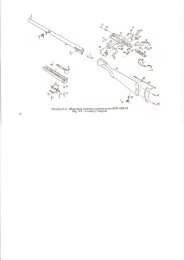
12. Exploded View.....................................................................23<br />
List of Charts<br />
Charts:<br />
1. Powder Bushings ...................................................................20<br />
2. Bill of Materials .....................................................................21<br />
2
SHOTSHELL RELOADER INSTRUCTIONS<br />
To help you load <strong>com</strong>pletely satisfactory ammunition the first time you operate your <strong>366</strong> Auto,<br />
these instructions have detailed steps of operation and adjustment to help in avoiding problems.<br />
To begin loading shot shells, you will need powder, shot, primers and wads, in addition to empty<br />
hulls. Before purchasing any of these <strong>com</strong>ponents, first note what charge the standard bushing<br />
furnished with your loader will throw by weighing your charge. Listed on the label on the outside<br />
of the carton is a powder bushing and shot bushing number which is referenced to a powder weight<br />
and brand, as well as shot amount and type.<br />
STANDARD LOADS AND BUSHINGS<br />
If the referenced powder in not available, refer to the re<strong>com</strong>mended load chart furnished with this<br />
loader. This chart will show the other powder weights and brands it will dispense. It is not to be<br />
taken for a reloading manual. Loading data from the major powder manufactures is furnished,<br />
when available, to help you in getting started. Unless you have experience in shot shell reloading,<br />
ask your dealer to help you pick the best starting <strong>com</strong>bination, or contact <strong>Hornady</strong>’s Reloading<br />
Advisory Center.<br />
IMPORTANT: Never mix powders or use unidentified powder. Do not use smokeless powder<br />
in old firearms until the firearm is certified safe. Do not exceed re<strong>com</strong>mended loads.<br />
Your <strong>366</strong> Auto is a precision machine. It is the only loader to feature full-length resizing with<br />
each stroke, automatic primer feed, swing-out wad guide, three stage crimping with taper-loc for<br />
factory tapered crimp, automatic advance to the next station and automatic ejection with the option<br />
of a gas assisted automatic advance.<br />
This press should give you many years of enjoyable, trouble-free service. Any problems that you<br />
have can generally be corrected by slight adjustments of the dies and punches in each station. If<br />
you are unable to correct the problem, please write us or call:<br />
<strong>Hornady</strong> Mfg. Co.<br />
PO Box 1848<br />
Grand Island, NE 68802-1848<br />
800-338-3220<br />
DO NOT RETURN THE LOADER TO YOUR DEALER.<br />
3
SETTING UP YOUR <strong>366</strong> <strong>AUTO</strong><br />
Mount your <strong>366</strong> Auto securely toward the front of a sturdy bench. All operations of the press are<br />
to a full stop, so the operating handle must clear the bench when in the down position. Since the<br />
shells are ejected down a chute, out the back of the loader, you may want to set your loader up on<br />
riser blocks (010060) to provide access to the <strong>com</strong>pleted shells. An alternate method to catch<br />
finished shells would be to cut a hole in the bench and place a box underneath.<br />
1. Before filling the shot and powder hoppers, turn the measure assembly upside down and<br />
carefully push the charge bar out and check the powder and shot bushing numbers.<br />
2. Your loader was furnished with standard bushings, 12 GA. 1 ⅛ oz. #7 ½ shot, 468 Powder<br />
Bushing; 20GA. ⅞ oz. #9 shot, 393 Powder Bushing; 28 GA. ¾ oz. #9 shot, 303 Powder<br />
Bushing; 410 GA. ½ oz. #9 shot, 291 Powder Bushing but double check to insure you will<br />
dispense the correct weight of powder and shot.<br />
3. While the charge bar is removed or pushed back, check that the measure casting seals<br />
(rubber washers) are in the recess in the measure casting.<br />
4. Reinstall the bushings and push the charge bar back in place. If the powder slide should<br />
drop out of the measure assembly, do not disassemble the measure plate.<br />
5. Replace the powder slide by pressing it in from the side against the detent spring, pull<br />
spring back and fit into slot.<br />
6. Reinstall the measure assembly by tilting the casting as you slip the measure plate and shot<br />
rotor spring under the hold down washer, and the charge bar into the slot of the charge bar<br />
cam.<br />
7. Secure assembly in position with measure attaching bolt.<br />
8. Install the primer tube in the die head casting and fill the primer tray according to<br />
instructions furnished with it. Do not fill the tube at this time.<br />
9. Check the individual stations of the loader for alignment to make sure nothing has loosened<br />
during shipping. Shut off the powder slide (push in) and the shot rotor (pull forward) while<br />
checking each station.<br />
READ THIS SECTION BEFORE ATTEMPTING TO LOAD AMMUNITION!<br />
4
FUNCTION AND ADJUSTMENT<br />
Fig. 1: Function and Adjustment<br />
The following is a detailed description of the operation and adjustment of the <strong>366</strong> Auto<br />
Reloading Press. This press has been pre-adjusted at the factory for Remington STS cases, but<br />
every person has a preference about how the finished product should look, so some changes might<br />
be necessary. The reloader should begin by advancing a single shell through each station to<br />
familiarize himself with the operation and adjustment of each position. The illustrated<br />
discussion which follows shows the <strong>366</strong> with all eight stations filled. Since your first shell will be<br />
the only one in the loader, be sure the shot and powder slides are off at the beginning of the<br />
sequence.<br />
Sort your shot shells by brand and type. Refer to the loading manuals provided for<br />
re<strong>com</strong>mended loads for your shot shells.<br />
5
Step 1: STATION 1A (Resize and Deprime)<br />
Fig. 2: Resize and De-Prime<br />
Place an empty shell in Station 1A, making sure the deprime punch enters the case mouth<br />
and the shell is reasonably centered under the size die (#14). Pull the operating handle (#37) to the<br />
bottom of the stroke. Make sure nothing interferes with the handle reaching bottom. When the<br />
operating handle is pulled, the platen casting (#107) rises until the eccentric arm stop (#111)<br />
contacts the base casting (#100). At this point, the shell should be <strong>com</strong>pletely enclosed in the size<br />
die (#14) and there should be no gap between the size die ring cap (#19) and the platen casting<br />
(#107). When the handle (#37) is returned, the de-prime punch guide (#8) pushes the case from the<br />
die. The expander (#8) is threaded on the deprime bolt (#62) which is forced down by the clevis<br />
link (#13) attached to the head casting (#7). The size die (#14) should size the brass head and rim<br />
to permit the chambering of that shell in any firearm. Properly adjusted, the size die (#14) just<br />
contacts the platen casting (#107). All other dies are set from this adjustment point, but are<br />
designed with all stations full. Interference with the handle (#37) can cause light powder charges<br />
or primers not seated properly. The size die (#14) and the size die ring cap (#19) must be kept tight<br />
at all times.<br />
6
Step 2: STATION ONE (De-prime Only)<br />
Fig. 3: De-Prime<br />
Insert the case in station.<br />
1. Normally, at this time, we would fill the primer tube (#2), but since we are working with a<br />
single shell, drop only one primer from the tray (#1) into the primer tube (#2). Now pull the<br />
handle (#37). As the handle (#37) makes a <strong>com</strong>plete cycle, the shell will automatically<br />
advance to the next station also dropping the primer into the hole in the primer seat pad<br />
(#3). Some individuals may wish to bypass Station 1A but a shell must be in place in<br />
Station 1 before pulling the handle (#37). The shell automatically advances on the return<br />
stroke and if Station 1 is empty, there will be a gap in the reloading sequence.<br />
Primer Drop: Until you are more familiar with your reloader, always return the handle<br />
smoothly and, at first slowly. The primer is dropped when the shell plate (#45) contacts the<br />
plastic primer drop stop unit (#78) at the bottom of the down stroke, and spreads the fingers of<br />
this unit, allowing the primer to slip into the hole provided in the shell plate (#45). At this<br />
point, make sure that the metal portion of the primer feed body (#42) does not make contact<br />
with the shell plate. Such contact will turn a burr on the inside and prevent primers from<br />
falling.<br />
The primer seat pad (#3) is notched to improve the primer drop, but the primer only falls at<br />
the speed of gravity, so the handle (#37) must not be raised too rapidly, or the primer could be<br />
jammed between the shell plate (#45) and the platen casting (#107). Therefore, operate the<br />
handle smoothly, and only as fast as primers will reliably drop into the primer seater pad (#3).<br />
7
Step 3: STATION TW0 (Prime)<br />
Fig. 4: Prime<br />
Pull the handle (#37) through a <strong>com</strong>plete stroke. The primer seating punch (#20) or the<br />
optional spring loaded primer seater punch (010051) will enter the case and push the case<br />
down, over the primer in the primer seating pad (#3). On the return stroke, the primer seating<br />
pad (#3) will push the case back up into position and the shell plate (#45) will advance to the<br />
next position. Before continuing the loading sequence, remove the primed case, to inspect the<br />
primer seat depth. To remove, lift the pawl (#94) from the indexing position and rotate the<br />
shell plate (#45) back to station one and inspect the seated primer. The primer should be flush<br />
with the case head. If the primer is not fully seated, the primer seater punch (#20) must be<br />
adjusted. Different brands of cases have different base wad heights. Replace the case in<br />
position at Station Two. Loosen the primer punch lock nut (#23). Pull the handle (#37) down,<br />
and steadily lower the primer seater punch until you feel the punch start to interfere with the<br />
handle (#37). The primer seating punch (#20) should then be backed up just enough to<br />
eliminate any interference. Your loader was factory set to load the low base wad of the modern<br />
<strong>com</strong>pression formed type cases and may not need any adjustment. The primer seater pad notch<br />
should be on your right as you face the loader.<br />
8
Step 4: STATION THREE (Drop Powder)<br />
Fig. 5: Powder Drop<br />
Before pulling the handle (#37), pull the powder slide (#69) toward you. The spring (#71)<br />
will lock the slide in place in the second slot of powder slide (#69). The powder drop is now<br />
on. During the stroke, the powder bushing will advance to the Powder Drop station.<br />
Normally, we would leave the powder slide on, but since we are taking one shell through each<br />
step, push the powder slide back and shut off the powder. (Do this before pulling the handle<br />
again.)<br />
There is no adjustment to the powder drop, but the drop tube should be kept clean and dry and<br />
must be able to float freely in the head casting. To clean the drop tube, use brake cleaner to<br />
remove all oils.<br />
9
Step 5: STATION FOUR (Wad Seating)<br />
Fig. 6: Wad Seating<br />
Insert a wad in the wad guide (#106A). Pull the operating handle (#37) through a <strong>com</strong>plete<br />
stroke. When the handle (#37) is pulled, the spring (#106B) around the wad guide rod (#105)<br />
turns the wad guide bracket (#101) to align the wad with the case. The unit then rises until the<br />
wad is stopped with the platen casting (#107) by the wad ram (#48). The case continues<br />
upward until the spring fingers (#77) have entered the case mouth, and then pushes the wad<br />
guide (#101) upward until the wad is seated in the case. The spring fingers (#77) have enough<br />
resistance to prevent the wad from going through until the spring fingers (#77) are in the case.<br />
At the <strong>com</strong>pletion of the return stroke, the wad guide bracket (#101) will swing forward for the<br />
next wad to be inserted. The wad guide bracket should have 1/8” clearance above the<br />
shells. The empty shells vary in length so a closer setting would not be beneficial. Be sure the<br />
wad seating ram (#48) is set high enough for the wad to swing into position with out being<br />
folded by early contact with the wad seating ram (#48). Wad pressure is adjusted by raising<br />
or lowering the wad seating ram (#48). Most one-piece plastic wads today will self-adjust<br />
when the shell is crimped. Generally, the wad should be seated to allow 5/8” clearance<br />
between the case mouth and the shot.<br />
10
Step 6: STATION FIVE (Shot Drop)<br />
Fig. 7: Shot Drop<br />
Before pulling the handle (#37), rotate the shot shut-off (#70) backward, turning on the<br />
shot. Now, lower the handle (#37). The shot drop tube (#47) enters the case mouth and then<br />
both case and shot drop tube (#47) rise together to the top of the stroke. In this fashion, all the<br />
shot enters the case without being spilled. No adjustment of this station is possible. Upon<br />
<strong>com</strong>pletion of the stroke, the shells will advance to the next station. Normally, we would leave<br />
the shot drop on, but since we are taking a single shell through the sequence, rotate the shot<br />
rotor (#70) forward to shut off the shot.<br />
11
Step 7: STATION SIX (Crimp Start)<br />
Fig. 8: Crimp Start<br />
As you lower the handle (#37), the shell at Station Six enters the crimp starter (#82). The<br />
plastic body has ridges on the inside to align with the old crimp and restart the folds. The<br />
outside of each crimp starter (#82) has a ridge corresponding with the inside, so if manual<br />
alignment is necessary with damaged crimps, follow these ridges. A hole in the case mouth of<br />
¼” should be left when the shell <strong>com</strong>pletes this station. <strong>Hornady</strong> loaders <strong>com</strong>e with eight<br />
point crimp starter installed, but if you are using another crimp, substitute with either smooth<br />
for paper or six point plastic, included with your loader. The plastic starter unit unthreads from<br />
the rod (#65) extending through the main body. The amount of “start” may be adjusted, but too<br />
much can cause the wall of the case to collapse, producing a defective shell.<br />
12
Step 8: STATION SEVEN (Crimp)<br />
Fig. 9: Crimp<br />
As you pull the handle (#37), the shell in Station Seven will enter the crimp die (#59). The<br />
shell will contact the inside of the die and raise the die body (#59) as it goes up. It will then<br />
contact the crimp plunger (#58) and the crimp will be closed. On the return stroke, the shell<br />
will be pulled from the crimp plunger (#58) but the crimp die (#59) will keep pressure on the<br />
case to retain the proper shape. Since different manufactures’ cases have varying types of<br />
construction, different settings are required for best results. The two-stage die enables the user<br />
to create a reloaded round that has approximately the same tapered mouth as a factory shell.<br />
There are two adjustments to the crimp die assembly (#57, #58, and #59); the larger outer<br />
position adjusts the die body (#59), the threaded bolt through the center of the die adjusts the<br />
crimp plunger (#58). To adjust the die, refer to the number of threads exposed above the large<br />
die body locking nut (#15) as reference points for each brand of case. For Winchester AA type<br />
shells, ten to ten and one half threads should remain above the locking ring (#15); for<br />
Remington Blue Magic and Federal Gold Metal Cases, eleven to thirteen threads should be<br />
exposed. These measurements are approximate and may need adjustment up or down,<br />
depending on the plastic and <strong>com</strong>ponents, but should be correct in most situations. Before<br />
adjusting the crimp the crimp die (#59), the crimp plunger (#58) should be raised a few turns<br />
by loosening lock nut (#15) and turning the crimp die bushing (#57) clock wise. Then, make<br />
the necessary die body (#59) adjustments, and follow by crimping the case. At this point, the<br />
case mouth will not be closed. Lower the crimp plunger (#58) in small increments, each time<br />
recrimping the shell until the final desired crimp depth is obtained. The crimp depth is up to<br />
you, but excessive depth shortens case life, while a crimp that is too shallow will not yield<br />
uniform velocity or good patterns. A good practice is to keep a factory round on hand for<br />
reference<br />
13
Step 9: STATION EIGHT (Taper Crimp)<br />
Fig. 10: Taper Crimp<br />
The taper crimp is a smooth crimp starter (#82) and will taper the finished case better than<br />
factory loads. As the shell at Station Eight enters the taper crimp die (#59), the mouth of the<br />
shell will be “rolled.” On the return stroke, the shells advance, but the shell in Station Eight<br />
contacts a cam in the platen casting (#107), moves to the left, and drops through a hole in the<br />
platen casting (#107) down the chute (#108) to the back.<br />
Adjustment of the taper crimp (#82) is done by loosening the lock nut (#29) and raising or<br />
lowering the taper crimp starter (#82) to obtain the desired taper on the case mouth.<br />
At this point in a normal reloading sequence, you would have a <strong>com</strong>pleted shell at each<br />
station. To begin reloading, go back to the beginning and follow instructions for Step 1<br />
and Step 2, but this time fill the primer tube (#2) when you insert a shell in Station One.<br />
As the shells advance around the loader, remember to turn on the powder and shot when<br />
the shells advance to the positions, and to reinsert a shell at Station One and a wad in the<br />
wad guide after each pull of the handle. You can continue the sequence until all your<br />
empty shells have been reloaded but always remember to check the powder and shot<br />
hoppers (#80) and make sure a primer drops on each stroke. If you refill the primers,<br />
shot and powder after each 100 rounds, you will never load shells without <strong>com</strong>ponents.<br />
14
ADJUSTMENT OF <strong>AUTO</strong> ADVANCE<br />
Fig. 11: Adjustment of Auto Advance<br />
When the operating handle (#37) is pulled all the way up, a spring (#98) swings the pivot<br />
arm (#85) and the advance pawl (#94) to your right. The hook of the pawl rides in the gap<br />
between the shell plate (#45) and the shell plate ring (#110). On the return stroke, the roller on<br />
the base casting (#100) contacts the curve on the pivot arm (#85) and the entire unit is cammed<br />
toward the left, advancing the shells to the next position. The cam bearing (#12) is mounted<br />
off-center on the bolt (#25) so when it is turned, the cam bearing is shifted right or left. If an<br />
adjustment is necessary, loosen the lock nut (#28) and turn the eccentric bolt (#93) with a<br />
screwdriver. It is necessary to hold the eccentric bolt (#93) with the screwdriver when<br />
tightening the nut (#28).<br />
15
TROUBLESHOOTING<br />
Handle will not <strong>com</strong>e to bottom of stroke<br />
Do not force the handle (#37). If you meet with any resistance, shut off the shot and powder<br />
and slowly return the handle (#37) back to normal while unlatching the rotating pawl (#94).<br />
1. Check to see the loader is mounted near the front of the bench, allowing the handle (#37) to<br />
<strong>com</strong>e <strong>com</strong>pletely down.<br />
2. Check to see if the size die body (#14) adjustment has changed or if the size die ring cap<br />
(#19) has loosened.<br />
3. Check that the de-prime punch guide (#8) is threaded all the way up on the size die ejector<br />
bolt (#62).<br />
4. Check to see that you are not seating a second primer on top of an already primed case.<br />
5. Check the primer seater punch (#20) to see if it is adjusted too low. Readjust to seat the<br />
primer when the handle (#37) is depressed.<br />
6. Check to see that you aren’t trying to seat a second wad on top of another and the wad<br />
entered the shell correctly.<br />
7. Check to see that shells are in alignment and the correct shell is in each station.<br />
8. Check for an obstruction inside the shell which would prevent you from depriming or<br />
repriming the case.<br />
9. Check to see that you aren’t trying to load a high base wad shell when you are set up for<br />
low base wads.<br />
10. Check to see if a loaded shell has rolled underneath one of the eccentric arms.<br />
Handle will not turn to normal position on backstroke.<br />
DO NOT FORCE THE HANDLE. Shut off the powder and shot and unlatch the rotating<br />
pawl (#94).<br />
1. Check the clevis link (#13) to see if it is bent and hanging up on the size die eject bolt<br />
(#62). Replace if necessary.<br />
2. Check the primer seater station to see that the primer was fully seated. If not, lower the<br />
primer seater punch (#20).<br />
3. Check to see that the wad is being fully seated and not pulling back up into the wad guide<br />
bracket (#101).<br />
16
4. Check the wad guide bracket (#101) to see that the wad guide return spring (#106B) is<br />
attached and that the bracket is fastened to the wad guide rod (#105).<br />
5. Check the charge bar cam (#9) adjustment to see that it hasn’t slipped.<br />
6. Check for an obstruction, spilled shot, etc., between the shell plate ring (#110) and the<br />
platen casting (#107). If there is, you may need to rotate the pawl (#94) clock wise and<br />
take the shell plate nut (#91) off and lift the shell plate (#45) off the platen (#107) and clean<br />
out the shot. When the shot is cleaned out, replace the <strong>com</strong>ponents in reverse order as you<br />
took them off.<br />
7. Lift each shell up against the shell plate (#45) to see if a primer flange may be catching in a<br />
platen casting (#107) indention.<br />
8. Check to see if the shell plate (#45) is dragging on the shell retainer spring (#63).<br />
9. Check to make sure the primer was fully removed at Station One.<br />
Primers do not drop or drop erratically.<br />
If primers do not drop into the shell plate (#45), or drop erratically, shut off the shot and<br />
powder and unlatch the rotating pawl (#94).<br />
1. Make sure the primer feed body (#42) is adjusted low enough to open the primer stop unit<br />
(#78) which allows a primer to drop.<br />
2. Check alignment of primer feed body (#42) with the shell plate (#45). The taper of the<br />
primer feed body (#42) should enter the chamfer in the shell plate (#45), but not touch.<br />
When there are no shells in the crimp die (#59), pressure on the size die (#14) may tip the<br />
platen casting (#107) enough to cause erratic drop. When possible, make adjustments with<br />
all stations full.<br />
3. Check that the auto advance unit (#83) is fully advancing and stopping in the correct<br />
location.<br />
4. See that the primer feed body (#42) is not burred on the inside, preventing the primers from<br />
dropping freely. If burred, remove with small file.<br />
5. Check the primer feed body (#42) to see that it is not burred on the ends and that it is<br />
straight.<br />
6. Inspect the plastic primer top unit (#78) for flash around the fingers and make sure that the<br />
foot moves freely on the body.<br />
Wads are not seating properly, tearing or tipping.<br />
Shut off the powder and shot and detach the rotating pawl (#94) and return the handle (#37) to<br />
normal position. DO NOT force the handle (#37) back, as it may not be able to move due to the<br />
17
swinging wad guide (#101). You may have to cut the wad in half if it cannot be pushed through<br />
into the case.<br />
1. Check your operation of the tool, making sure you allow enough time for the wad to<br />
correctly align with the ram. The wad guide (#106) should be set to swing out just far<br />
enough for easy insertion of the wad; swinging too far will delay the bracket.<br />
2. Make sure the wad guide bracket (#101) clears the shell by about 1/8” so the spring fingers<br />
(#77) enter the case mouth before the wad starts through.<br />
3. Check shell length; variations may cause the case mouth to catch on the bottom of the wad<br />
guide (#106); preventing it from aligning correctly.<br />
4. Check the E clip (#104), which is about 3” from the bottom of the wad guide rod (#105), to<br />
see if it has slipped or broken off the wad guide rod (#105); it could allow the wad to move<br />
through the spring fingers (#77) before they enter the case mouth.<br />
5. Check the spring fingers (#77) to see if they are broken or weak.<br />
6. Check the shells to see that the case mouth is opened up enough to allow the wad to be<br />
seated. Case mouths which are too tight must be flared open, either by hand or with an<br />
expander in the size die (#14) or de-prime station (#1A).<br />
Crimp is concave or opens after being ejected from die. Crimp not satisfactory in<br />
appearance. Detach the rotating pawl, shut off the powder and shot.<br />
1. If the crimp is concave (sinks):<br />
a. Reduce the wad seating depth to see that the shot <strong>com</strong>es to about 5/8” from the case<br />
mouth in the crimp starter station.<br />
b. Check to see if powder slide is turned on.<br />
c. See if you have correct powder bushing.<br />
d. Make sure the wad length is correct for the case you are loading.<br />
e. Check to see if the shot bushing is correct. Adjust the crimp plunger (#58).<br />
2. If the crimp is bulging open:<br />
a. Check to see if you have seated the wad deep enough.<br />
b. Inspect powder bushing to insure correct powder charge used.<br />
c. Check shot bushing for shot size used.<br />
d. Make sure you have the correct wad length for load being used<br />
18
e. Double-check all <strong>com</strong>ponents to make sure they are the correct ones for the specific<br />
load.<br />
f. Check adjustment of crimp plunger (#58).<br />
3. If the finished shell does not have enough taper in the end or is flared, lower the taper<br />
crimp die (#82) (Station Eight).<br />
4. If crimp isn’t deep enough, turn the crimp plunger (#58) in the final crimp down.<br />
5. If the shell swirls in the center, the plastic shell has elongated or stretched. No adjustment<br />
is generally possible to remove the swirl. This is <strong>com</strong>mon, and was probably in the factory<br />
shell.<br />
6. Check to see that you have the proper crimp starter (#82) installed. Eight point for most<br />
plastic target cases, six point for most plastic hunting loads and smooth for paper cases. If<br />
the case buckles at the mouth or wrinkles after final crimp or during the crimp start, raise<br />
the crimp starter. Also check to insure you have the correct <strong>com</strong>ponents.<br />
Converting to another gauge.<br />
If you purchase a die set for a different gauge, always remember to start installation by<br />
adjusting the full length size die (#14) FIRST! When adjusted properly, the size die should just<br />
contact the platen (#107) at the top of the stroke. Then, install other dies and punches using the<br />
size die (#14) as a guide. Stations should be adjusted by actually reloading a shell. The exception is<br />
the primer seating pad (#3) to ensure seating the primer to the full depth of the primer pocket.<br />
Adjust the wad ram (#46) to provide best crimp (except as noted in sinking crimps or bulging).<br />
By showing you how to “fine tune” and troubleshoot the <strong>366</strong> Auto, we hope to save you<br />
downtime and maximize your reloading enjoyment. Your <strong>366</strong> Auto is a fine progressive<br />
reloader…once the first cycle is <strong>com</strong>pleted; it kicks out a finished shell with every stroke.<br />
ABOUT WADS AND WAD PRESSURE: We re<strong>com</strong>mend the use of 1-piece plastic wads. They<br />
are more convenient, and do not require any specific wad pressure. They need to be seated only<br />
deep enough to obtain a satisfactory crimp.<br />
PLEASE NOTE: Normally, few problems are encountered when reloading shot shells. However,<br />
variations in the powder lot, different brands of primers and other <strong>com</strong>ponents can cause<br />
substantial changes in pressure. <strong>Hornady</strong> Mfg Company has no control over the <strong>com</strong>ponents and<br />
equipment which may be used with this published information; no responsibility is implied or<br />
assumed for modern firearms and does not exceed manufacturer’s pressure re<strong>com</strong>mendations.<br />
Further data may be obtained from:<br />
Hercules Powder Company Dupont Explosive Products Winchester Division<br />
Mr. Don Burton Mr. Don Wenner Mr. Ted Henshaw<br />
910 Market Street Wilmington, DE 1938 Olin Corp.<br />
Wilmington, DE 1939 Shamrock St.<br />
East Alton, IL 62024<br />
19
Powder/Grains<br />
Accurate Nitro 100<br />
IMR 700-X<br />
IMR PB<br />
IMR SR 7625<br />
IMR 800-X<br />
IMR SR 4756<br />
IMR MR 4227<br />
Alliant American Select<br />
Alliant Red Dot<br />
Alliant Green Dot<br />
Alliant Unique<br />
Powder Bushing Chart<br />
Alliant Herco<br />
Alliant Blue Dot<br />
Alliant 2400<br />
Alliant E-3<br />
Alliant 410<br />
20<br />
Hodgdon Clays<br />
10 330 256<br />
11 256 266<br />
12 384 363 266 291 250<br />
13 336 393 378 342 357 - 300 363 330 256 259 363 256<br />
14 <strong>366</strong> 345 363 405 390 354 369 291 266 300 266<br />
15 402 372 <strong>366</strong> 303 423 405 369 381 300 426 390 354 - 384 309 324<br />
16 414 390 390 438 420 381 393 312 438 429 402 <strong>366</strong> 303 291 396 318 330 330<br />
17 420 429 402 381 402 423 453 435 393 405 324 450 441 414 312 300 408 330 342 447 300 345<br />
18 432 441 414 390 414 432 468 447 405 414 <strong>366</strong> 330 465 456 423 390 318 309 420 339 351 456 420 309 417 354<br />
19 444 453 426 402 423 408 447 480 456 414 426 372 339 477 468 435 402 327 318 315 432 348 360 468 432 318 318 429 363<br />
20 456 465 435 414 429 417 456 489 468 423 438 381 483 447 336 330 324 441 357 369 480 444 327 330 438 372<br />
21 468 447 426 438 426 357 468 498 480 435 450 390 459 420 345 339 453 <strong>366</strong> 378 456 336 339 450 381<br />
22 486 456 438 447 435 <strong>366</strong> 510 492 444 462 396 471 429 354 348 462 372 387 504 468 345 348 459 390<br />
23 498 465 444 459 447 519 501 453 471 408 438 363 357 474 381 396 480 351 357 471 402<br />
24 474 453 468 459 513 465 477 414 447 369 363 486 390 405 489 360 363 480<br />
25 486 462 480 471 390 522 474 489 423 507 456 378 369 492 396 498 <strong>366</strong> 369<br />
26 474 489 480 534 483 498 435 468 387 378 405 375 378 420<br />
27 486 489 408 - 492 - 441 480 393 384 414 381 384 426<br />
28 507 414 549 501 513 447 489 402 390 423 387 390 432<br />
29 525 420 558 - 522 459 408 396 429 393 396 441<br />
30 426 510 531 468 414 405 435 402 405 450<br />
31 534 435 - 474 420 411 444 408 411 456<br />
32 525 441 549 483 429 417 450 414 417 462<br />
33 549 534 447 558 489 435 423 459 423 423<br />
34 558 543 453 564 495 441 429 465 429 429<br />
35 549 462 573 501 447 438 471 435 438<br />
36 558 468 - 510 453 444 480 441 444<br />
37 474 588 516 459 450 486 444 450<br />
38 480 594 522 465 492 450 456<br />
39 580 486 531 471 498 459 462<br />
40 588 534 465 468<br />
41 498 534 471 474<br />
42 549 477 480<br />
43 555 483 486<br />
44 561 489 492<br />
Hodgdon International<br />
Hodgdon Universal<br />
Hodgdon HS-6<br />
Hodgdon HS-7<br />
Hodgdon H110<br />
Hodgdon Titewad<br />
Hodgdon Lil' Gun<br />
Hodgdon LGSH<br />
Hodgdon Titegroup<br />
Scot 1000<br />
Solo 1250<br />
Win. 540<br />
Win. 571<br />
Win. 296<br />
Win. Super Target<br />
Win. Super Lite<br />
Win. Super Field
Bill of Material<br />
Item# Qty Part # Description Item# Qty Part # Description<br />
1 1 020003 Assembly 30 2 390100 Guide Post<br />
1 480032 Movable Lid 31 4 390101 Guide Post Bolt<br />
1 398415 Panhead Screw 32 1 398120 Pivot Shaft<br />
1 480034 Knob 33 2 398121 Eccentric Arm<br />
1 480031 Fixed Lid 34 2 390105 Drive Link<br />
1 390633 Spring 35 2 390106 Drive Link Roll Pin<br />
1 480030 Body 36 2 390107 Platen Drive Bolt<br />
1 480033 Rotor 37 1 390657 Operating Handle<br />
2 1 050025 Primer Tube Assembly 38 1 390027 5/8-18 Jam Nut<br />
1 390180 Ferrule 39 1 390119 Bearing Pin<br />
1 290001 Ferrule Tube 40 1 390124 Clevis Rod<br />
3 1 050040 Primer Seater Assembly 41 2 390125 Clevis Rod Bushing<br />
1 370047 Spring 42 1 390126 Primer Feed Body<br />
Measure Plate Hold-Down<br />
1 390069 Screw 10-32 x 1 1/2 43 1 390127 Screw<br />
1 390068 Primer Pad Measure Plate Hold-Down<br />
44 1 390128 Washer<br />
1 390065 Well Nut 45 1 390129 12 Ga. Shell Plate<br />
1 392011 Hex Nut 10-32 1 390141 20 Ga. Shell Plate<br />
1 390086 Locating Pin 1 390147 28 Ga. Shell Plate<br />
4 OBSOLETE 1 392078 410 Ga. Shell Plate<br />
5 1 190003 Measure Casting 46 1 390132 12/16 ga. Powder Drop Tube<br />
6 1 190007 Charge Bar 1 390144 20 Ga. Powder Drop Tube<br />
7 1 190008 Die Head Casting 410/28 Ga. Powder Drop<br />
Deprime Punch Guide, 12<br />
1 390156 Tube<br />
8 1 190033 Ga.<br />
Deprime Punch Guide, 20<br />
47 1 390133 12/16 ga. Shot Drop Tube<br />
1 190035 Ga. 1 390145 20 Ga. Shot Drop Tube<br />
1 190036 Deprime Punch 28 Ga. 1 390157 410/28 Ga. Shot Drop Tube<br />
1 190037 Deprimer Punch 410 Ga. Deprime Punch 20 Ga., 28<br />
47A 1 390155 Ga., & 410 Ga.<br />
9 1 190049 Charge Bar Cam 1 390134 Deprime Punch 12 Ga.<br />
10 OBSOLETE 48 1 390146 12/16 Ga. Wad Ram<br />
11 1<br />
Detent Ball & Spring<br />
380050 Assembly 1 390158 20 Ga., 28 Ga., Wad Ram<br />
12 2 380100 Cam Bearing 1 390152 410 Ga. Wad Ram<br />
13 1 390014 Clevis Link 49 1 390179 Shell Plate Washer<br />
14 1 390019 Shotshell Size Die Body 50 1 390186 Clevis Rod Bolt<br />
15 2 390020 Die Body Lock Nut<br />
Wad Rod Spring 20 Ga., 28<br />
51 2 390187 Set Screw<br />
16 1 390021 Ga. & 410 Ga. 52 1 390188 Measure Attaching Bolt<br />
10-32 x 3/8 Screw (12 Ga.,<br />
17 OBSOLETE 53 3 390095 20 Ga. & 28 Ga.)<br />
Set Screw 10-32 5/8 (410<br />
18 OBSOLETE 53 1 390190 Ga. Qty. 3)<br />
19 1 390029 Size Die Ring Cap 12 Ga. 54 2 390196 Split Washer 3/8<br />
1 390031 Size Die Ring Cap 20 Ga. 55 1 390198 Crimp Die Spring<br />
1 390032 Size Die Ring Cap 28 Ga. 1 392080 410/28 Ga. Crimp Die Spring<br />
1 390033 Size Die Ring Cap 410 Ga. 56 2 390201 Bearing Pin E Clip 7/32<br />
12/16 ga. Primer Seater<br />
Crimp Die Bushing 12 Ga., &<br />
20 1 390038 Punch 57 1 390202 20 Ga.<br />
1 390040 20 Ga. Primer Seater Punch 410/28 Ga. Crimp Die<br />
390203 Bushing<br />
1 390041 28 Ga. Primer Seater Punch<br />
410 Ga. Primer Seater<br />
58 1 390204 Crimp Plunger 12 ga.<br />
1 392076 Punch 390206 20 Ga. Crimp Plunger<br />
21 OBSOLETE 390207 28 Ga. Crimp Plunger<br />
22 OBSOLETE 390208 410 Ga. Crimp Plunger<br />
12 Ga. 2 3/4" Crimp Die<br />
23 3 390087 9/16-18 Lock Nut 59 1 390212 Body<br />
24 2 390089 1/4-20 Hex Lock Nut 390213 12 Ga. 3" Crimp Die Body<br />
20 Ga. 2 3/4" Crimp Die<br />
25 2 390092 1/2-20 x 5/8" Bolt 390215 Body<br />
26 3 390093 Clevis & Cam Bolt 390216 20 Ga. 3" Crimp Die Body<br />
27 4 390098 Poly Hopper Rivet 390217 28 Ga. Crimp Die Body<br />
28 2 390096 1/2-20 Jam Nut 392075 410 Ga. Crimp Die Body<br />
29 3 390097 Lock Nut 3/8-16 60 1 390633 Primer Tube Filler Spring<br />
390178 Lock Nut 28/410 1/4-20 61 2 390066 Push Nut<br />
21
Bill of Material<br />
Item# Qty Part # Description Item# Qty Part # Description<br />
62 1 392053 Size Die Eject Bolt SWING OUT WAD GUIDE PARTS<br />
63 1 392054 Shell Retainer Spring O50036 Assembly (factory installed)<br />
64 2 392055 3/8 Flat Washer 100 1 190050 Base<br />
Swing Out Wad Guide<br />
65 2 392101 Crimp Starter Rod 101 1 190038 Bracket<br />
66 2 392102 Crimp Starter Bushing 102 1 190045 Return Spring Retainer<br />
Primer Feed Rod Roll Pin 1/8<br />
67 1 392103 Measure Plate 103 1 390167 x 1/2<br />
68 1 392104 Measure Plate Spacer 104 1 390120 E Clip 1/4<br />
69 1 392105 Powder Slide 105 1 392035 Wad Guide Rod<br />
70 1 392106 Shot Rotor Slide 106 1 390048 12 Ga. Wad Guide Body<br />
71 1 392107 Powder Slide Spring 390050 20 Ga. Wad Guide Body<br />
72 1 392108 Shot Rotor Slide Spring 390051 28 Ga. Wad Guide Body<br />
73 4 392109 Roll Pin 1/8 X 1/4 390052 410 Ga. Wad Guide Body<br />
74 2 480001 Measure Seals 106A 1 392041 12 ga. Wad Guide Cap<br />
75 1 480003 Plastic Handle Ball 392043 20 Ga. Wad Guide Cap<br />
76 1 480006 Primer Catcher 392044 28 Ga. Wad Guide Cap<br />
77 1 480007 12 Ga. Spring Finger 390047 410 Ga. Wad Guide Cap<br />
480009 20 Ga. Spring Finger 106B 1 392046 Wad Guide Return Spring<br />
480010 28 Ga. Spring Finger SHELL DROP PARTS<br />
480011 410 Ga. Spring Finger Shell Drop Assembly (factory<br />
O50035 installed)<br />
78 1 480028 Stop Unit 107 1 190046 Platen<br />
79 See Accessories 108 1 392052 Shell Chute<br />
Chute Screw 6-32 x 1/4 Pan<br />
80 2 490002 Shot/Powder Hopper Tube 109 3 390182 Head<br />
81 2 490003 Hopper Cap 110 1 392047 12 Ga. Shell Plate Ring<br />
82 1 490500 12 Ga. 8pt. Crimp Starter 1 392049 20 Ga. Shell Plate Ring<br />
490501 12 Ga. 6pt. Crimp Starter 1 392050 28 Ga. Shell Plate Ring<br />
490313 12 Ga. Paper Crimp Starter 1 392079 410 Ga. Shell Plate Ring<br />
490503 20 Ga. 8pt. Crimp Starter 111 1 392038 Eccentric Arm Stop<br />
490504 20 Ga. 6pt. Crimp Starter 112 1 390199 1/4 x 20 by 3/4<br />
490319 20 Ga. Paper Crimp Starter 113 1 390175 1/4 x 20 by 1/2<br />
490509 28 Ga. 6pt. Crimp Starter 114 2 398323 #10 FLAT WASHER<br />
490321 28Ga. Paper Crimper Starter Additional Parts for 410 Ga. Loader Only<br />
490511 410 Ga. 6pt. Crimp Starter 1 190060 Hull Guide (Primer) 410 Ga.<br />
490323 410 Ga. Paper Crimp Starter 1 190061 Hull Guide (Powder) 410 Ga.<br />
490512 10 Ga. 6pt. Crimp Stater Flaring Sleeve, 410 Ga. & 28<br />
1 392077 Ga.<br />
<strong>AUTO</strong>-ADVANCE PARTS 1 390710 Nylon Tip Set Screw 410 Ga.<br />
83 1 O50034 Auto-Advance Assembly 1 480081 O-Ring (Primer) 410 Ga.<br />
84 1 O50041 Pawl Assembly 1 480085 O-Ring (Powder) 410 Ga.<br />
85 1 190043 Pivot Arm 1 390157 Shot Drop Tube 410 Ga.<br />
86 1 380100 SAME AS 12<br />
87 1 390081 1/2" E Clip<br />
88 1 390084 Slotted Pin 1/8 x 1<br />
89 3 390093 Clevis & Cam Bolt<br />
6-32 X 3/4 FH SLTD (410<br />
90 1 390191 Ga.)<br />
91 1 390115 Shell Plate Bolt Nut (elastic)<br />
1 392440 Shell Plate Bolt Nut 410 Ga.<br />
92 2 390125 Clevis Rod Bushing<br />
2 392081 Spacer 410 Ga.<br />
93 1 390777 Eccentric Bolt<br />
94 1 392027 New Style Pawl<br />
1 392083 Pawl 410 Ga.<br />
95 1 392026 Shoulder Bolt<br />
Shoulder Bolt 410 Ga. 1/4 x<br />
1 392082 3/4<br />
96 1 392028 Shell Plate Bolt<br />
97 1 392029 Pawl Spring<br />
98 1 392030 Return Spring<br />
22