VW MKII A2 MK2 Golf Jetta Fox Service Manual - VAGLinks.com
VW MKII A2 MK2 Golf Jetta Fox Service Manual - VAGLinks.com
VW MKII A2 MK2 Golf Jetta Fox Service Manual - VAGLinks.com
You also want an ePaper? Increase the reach of your titles
YUMPU automatically turns print PDFs into web optimized ePapers that Google loves.
1 General information<br />
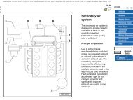
The 1.8 litre, 16-valve engine fitted to GTi<br />
models from October 1986, incorporates<br />
double overhead camshafts, one operating<br />
the exhaust valves and the other the inlet<br />
valves. There are four valves per cylinder<br />
which operate simultaneously in pairs and<br />
provide the engine with a much improved<br />
breathing capability over the 8-valve version,<br />
thus resulting in greater power output. A<br />
single camshaft sprocket is attached to the<br />
exhaust camshaft and a chain and sprocket at<br />
the opposite end of the cylinder head is used<br />
to drive the inlet camshaft (see illustration).<br />
Most overhaul procedures for the 16-valve<br />
engine are basically the same as those<br />
described for the 8-valve engine in Part C of<br />
this Chapter. The following Sections describe<br />
procedures which differ.<br />
2 Timing belt and sprockets -<br />
removal and refitting 3<br />
Besides the timing mark on the camshaft<br />
sprocket referred to in Part C of this Chapter,<br />
Section 9, an additional timing mark is<br />
provided on the outside of the camshaft<br />
sprocket which aligns with a mark on the<br />
valve cover (see illustration). This means that<br />
if the timing belt alone is being renewed, it is<br />
not necessary to remove the valve cover in<br />
order to check the alignment marks.<br />
When fitting the timing belt, it is<br />
re<strong>com</strong>mended that <strong>VW</strong> tool 210 is used to set<br />
the tension accurately as this is more critical<br />
with the DOHC arrangement (see<br />
illustration). Using this tool, the tension<br />
should be set to record a reading of between<br />
13 and 14 on the scale. The tool can be<br />
obtained from a <strong>VW</strong> dealer.<br />
A Camshaft sprocket outer marks<br />
B Camshaft sprocket inner marks<br />
C Crankshaft vibration damper marks<br />
3 Camshafts - removal and<br />
refitting 3<br />
Removal<br />
3.4 TDC timing marks in alignment on camshaft drive chain<br />
sprockets<br />
2.1 Valve timing marks<br />
1 Remove the camshaft sprocket cover.<br />
2 Unbolt and remove the upper section of<br />
inlet manifold.<br />
3 Unbolt and remove the valve cover after<br />
disconnecting the HT leads from the spark<br />
plugs. Remove the main gasket and the<br />
1081 <strong>VW</strong> <strong>Golf</strong> & <strong>Jetta</strong><br />
Engine repair procedures 1.8 litre 16 valve 2D•3<br />
2.2 Adjusting timing belt tension using<br />
<strong>VW</strong> tool 210<br />
central gasket from around the spark plug<br />
locations.<br />
4 Align the timing marks with reference to<br />
Part C of this Chapter, then check also that<br />
the marks on the chain sprockets are aligned<br />
(see illustration).<br />
5 Remove the timing belt and camshaft<br />
sprocket with reference to Part C of this<br />
Chapter.<br />
6 Note the fitted positions of the camshaft<br />
bearing caps, if necessary marking them to<br />
ensure correct refitting (see illustration).<br />
7 Progressively unscrew the nuts and bolts<br />
from the end caps and bearing cap Nos. 1<br />
and 3 on the exhaust camshaft.<br />
8 Progressively unscrew the bolts from<br />
bearing cap Nos. 2 and 4. The exhaust valve<br />
springs will force the exhaust camshaft up as<br />
the bolts are loosened. Remove the bearing<br />
caps keeping them identified for position.<br />
9 Working on the inlet camshaft, progressively<br />
unscrew the nuts and bolts from<br />
the end cap and bearing cap Nos. 5 and 7.<br />
10 Progressively unscrew the bolts from<br />
bearing cap Nos. 6 and 8, then remove all the<br />
caps keeping them identified for position.<br />
11 Lift both camshafts from the cylinder head<br />
then release them from the drive chain.<br />
3.6 Camshaft bearing cap identification<br />
Inset shows recessed corner position (arrowed)<br />
2D


