

VW MKII A2 MK2 Golf Jetta Fox Service Manual - VAGLinks.com
VW MKII A2 MK2 Golf Jetta Fox Service Manual - VAGLinks.com
VW MKII A2 MK2 Golf Jetta Fox Service Manual - VAGLinks.com

You also want an ePaper? Increase the reach of your titles
YUMPU automatically turns print PDFs into web optimized ePapers that Google loves.
and tappet is required. Label the containers 1<br />
to 8, as follows:<br />
Containers 1 and 2 will be No 1 cylinder<br />
exhaust and inlet respectively<br />
Containers 3 and 4 will be No 2 cylinder<br />
exhaust and inlet respectively<br />
Containers 5 and 6 will be No 3 cylinder<br />
inlet and exhaust respectively<br />
Containers 7 and 8 will be No 4 cylinder<br />
inlet and exhaust respectively<br />
5 Note the thickness of all tappet clearance<br />
discs from Nos. 1 to 8 for use during<br />
reassembly.<br />
Hydraulic bucket tappets<br />
6 Lift out the tappets one by one, ensuring<br />
that they are kept in their correct order and<br />
can be returned to their original bores.<br />
7 Place them, cam contact surface down, on<br />
a clean sheet of paper as they are removed.<br />
8 Inspect the tappets for wear (indicated by<br />
ridging on the clean surface), pitting and<br />
cracks.<br />
9 Tappets cannot be repaired and if worn,<br />
must be renewed.<br />
Examination<br />
10 Refer to Section 27 in Part A of this<br />
Chapter whilst noting that on exchange<br />
engines or cylinder heads, the camshaft is<br />
supplied with bearing shells instead of running<br />
directly in the head and bearing caps.<br />
Exchange units supplied by <strong>VW</strong> may have an<br />
undersized camshaft with corresponding<br />
bearing shells. Where this is the case, the<br />
camshaft will have a yellow paint spot on it<br />
and the journal diameter will be 25.75 mm. An<br />
unmarked camshaft supplied with bearing<br />
shells will be of standard size with a journal<br />
diameter of 26.00 mm.<br />
Refitting<br />
11 Refer to Section 12.<br />
11 Cylinder head - removal<br />
All engines<br />
3<br />
1 If the cylinder head is being removed with<br />
the engine out of the vehicle, proceed from<br />
paragraph 17. If the cylinder head is being<br />
removed with the engine in the vehicle, it is<br />
best removed with the inlet and exhaust<br />
manifolds. The manifolds can then be<br />
detached after removal of the cylinder head<br />
but note that a special tool is required to<br />
release (and subsequently reconnect) the<br />
exhaust downpipe-to-manifold flange retaining<br />
clips. A splined key will also be required to<br />
undo and tighten the cylinder head bolts.<br />
2 Disconnect the battery earth lead. Drain the<br />
cooling system, then disconnect the cooling<br />
and heater hoses from the cylinder head.<br />
3 Disconnect the thermoswitch and oil<br />
pressure lead connections.<br />
Engine repair procedures - 1.6 and 1.8 litre 8 valve 2C•11<br />
4 On carburettor models, remove the air<br />
cleaner unit.<br />
5 Disconnect the alternator from the cylinder<br />
head attachment brackets and remove the<br />
drivebelt.<br />
6 If removing the manifolds with the cylinder<br />
head, disconnect the vacuum hose from the<br />
inlet manifold and the accelerator cable (and<br />
choke cable if applicable) from the<br />
carburettor.<br />
7 Disconnect the HT leads from the spark<br />
plugs.<br />
Fuel injection equipped engines<br />
8 Detach the injector lines from the cylinder<br />
head and location clips and fold them back<br />
out of the way.<br />
9 Disconnect the inlet duct at the flexible<br />
hose connection to the throttle valve housing.<br />
10 Detach the vacuum hoses to the throttle<br />
valve housing and at the three-way connector<br />
on the bulkhead side of the cylinder head.<br />
Fold back and secure the hoses out of the<br />
way.<br />
11 Disconnect the auxiliary air valve lead<br />
from the underside of the inlet manifold and<br />
the auxiliary air valve hose to the flexible hose<br />
on the throttle valve housing.<br />
12 Disconnect the servo vacuum hose from<br />
the green connector on the flexible hose on<br />
the throttle housing.<br />
13 If air conditioning is fitted, detach the<br />
hoses from the auxiliary air valve and tube<br />
connections.<br />
14 Detach the MFI hose at the servo hose<br />
valve connection.<br />
15 Detach the wiring connector from the cold<br />
start valve.<br />
All engines<br />
16 Remove the timing cover and valve cover,<br />
then disconnect the timing belt from the<br />
camshaft sprocket.<br />
17 Remove the camshaft.<br />
18 Remove the cylinder head bolts. These<br />
are recessed in the well of the cylinder head<br />
and are socket-head bolts. They must be<br />
removed using the correct splined tool.<br />
19 The cylinder head bolts must be<br />
unscrewed in a progressive manner and in the<br />
reverse sequence to that shown for<br />
tightening.<br />
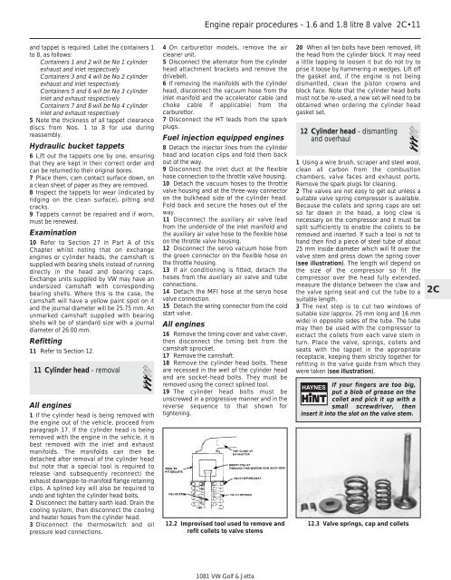
12.2 Improvised tool used to remove and<br />
refit collets to valve stems<br />
1081 <strong>VW</strong> <strong>Golf</strong> & <strong>Jetta</strong><br />
20 When all ten bolts have been removed, lift<br />
the head from the cylinder block. It may need<br />
a little tapping to loosen it but do not try to<br />
prise it loose by hammering in wedges. Lift off<br />
the gasket and, if the engine is not being<br />
dismantled, clean the piston crowns and<br />
block face. Note that the cylinder head bolts<br />
must not be re-used, a new set will need to be<br />
obtained when ordering the cylinder head<br />
gasket set.<br />
12 Cylinder head - dismantling<br />
and overhaul 3<br />
1 Using a wire brush, scraper and steel wool,<br />
clean all carbon from the <strong>com</strong>bustion<br />
chambers, valve faces and exhaust ports.<br />
Remove the spark plugs for cleaning.<br />
2 The valves are not easy to get out unless a<br />
suitable valve spring <strong>com</strong>pressor is available.<br />
Because the collets and spring caps are set<br />
so far down in the head, a long claw is<br />
necessary on the <strong>com</strong>pressor and it must be<br />
split sufficiently to enable the collets to be<br />
removed and inserted. If such a tool is not to<br />
hand then find a piece of steel tube of about<br />
25 mm inside diameter which will fit over the<br />
valve stem and press down the spring cover<br />
(see illustration). The length will depend on<br />
the size of the <strong>com</strong>pressor so fit the<br />
<strong>com</strong>pressor over the head fully extended,<br />
measure the distance between the claw and<br />
the valve spring seat and cut the tube to a<br />
suitable length.<br />
3 The next step is to cut two windows of<br />
suitable size (approx. 25 mm long and 16 mm<br />
wide) in opposite sides of the tube. The tube<br />
may then be used with the <strong>com</strong>pressor to<br />
extract the collets from each valve stem in<br />
turn. Place the valve, springs, collets and<br />
seats with the tappet in the appropriate<br />
receptacle, keeping them strictly together for<br />
refitting in the valve guide from which they<br />
were taken (see illustration).<br />
If your fingers are too big,<br />
put a blob of grease on the<br />
collet and pick it up with a<br />
small screwdriver, then<br />
insert it into the slot on the valve stem.<br />
12.3 Valve springs, cap and collets<br />
2C


