

VW MKII A2 MK2 Golf Jetta Fox Service Manual - VAGLinks.com
VW MKII A2 MK2 Golf Jetta Fox Service Manual - VAGLinks.com
VW MKII A2 MK2 Golf Jetta Fox Service Manual - VAGLinks.com

You also want an ePaper? Increase the reach of your titles
YUMPU automatically turns print PDFs into web optimized ePapers that Google loves.
4 If the indicators do not function correctly, a<br />
series of tests may be done to find which part<br />
of the circuit is at fault.<br />
5 The most <strong>com</strong>mon fault is in the flasher<br />
lamps, defective bulbs and dirty or corroded<br />
contacts or mountings. Check these first, then<br />
test the emergency switch. Remove it from<br />
the circuit and check its operation.<br />
6 If the switch is in good order, refit it and<br />
again turn on the emergency lights. If nothing<br />
happens, then the relay is not functioning<br />
properly and it should be renewed.<br />
7 If the lights function on emergency but not<br />
on operation of the column switch, then the<br />
wiring and column switch are suspect.<br />
10 Warning lamp cluster -<br />
removal and refitting 1<br />
1 Disconnect the battery earth lead.<br />
2 Remove the facia control switches then,<br />
reaching through the vacant switch apertures<br />
in the facia, <strong>com</strong>press the retainers and push<br />
out the warning lamp cluster unit (see<br />
illustration).<br />
3 Disconnect the multi-plug for full cluster<br />
removal.<br />
4 Withdraw the warning light bulbholder from<br />
the cluster and pull free the bulb for<br />
inspection and, if necessary, renewal (see<br />
illustration).<br />
5 Where two or more warning lamp bulbs are<br />
contained in a single mounting plate, the plate<br />
unit <strong>com</strong>plete must be renewed as it is not<br />
possible to renew a single bulb in this<br />
instance.<br />
6 Refit in the reverse order of removal. On<br />
<strong>com</strong>pletion, check the operation of the<br />
switches and warning light bulb(s).<br />
11 Ignition switch/steering<br />
column lock - removal and<br />
refitting<br />
2<br />
This procedure is described in Chapter 10<br />
for removal and refitting of the steering lock.<br />
12.6 Removing indicator switch . . .<br />
12 Combination switches -<br />
removal and refitting 2<br />
1 Remove the steering wheel.<br />
2 Disconnect the battery negative lead.<br />
3 Remove the screws and withdraw the<br />
steering column lower shroud.<br />
4 Remove the three screws securing the<br />
<strong>com</strong>bination switch (see illustration).<br />
5 Disconnect the multi-plugs (see illustration).<br />
6 Rotate the indicator switch clockwise and<br />
withdraw it, noting location of the plastic<br />
retaining arms (see illustration).<br />
7 Withdraw the wiper control switch from the<br />
column. Full removal of the switch of GTi<br />
models will necessitate detaching the<br />
additional wire from its connector under the<br />
dash panel (see illustrations).<br />
Body electrical systems 12•7<br />
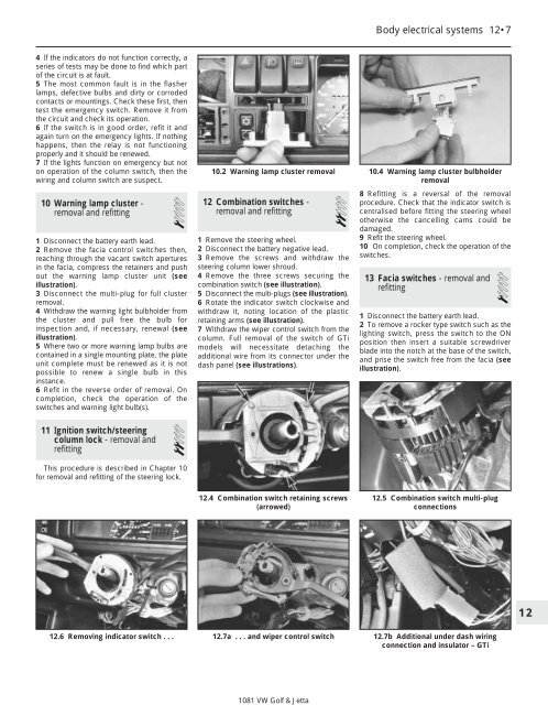
10.2 Warning lamp cluster removal 10.4 Warning lamp cluster bulbholder<br />
removal<br />
12.4 Combination switch retaining screws<br />
(arrowed)<br />
8 Refitting is a reversal of the removal<br />
procedure. Check that the indicator switch is<br />
centralised before fitting the steering wheel<br />
otherwise the cancelling cams could be<br />
damaged.<br />
9 Refit the steering wheel.<br />
10 On <strong>com</strong>pletion, check the operation of the<br />
switches.<br />
13 Facia switches - removal and<br />
refitting 1<br />
1 Disconnect the battery earth lead.<br />
2 To remove a rocker type switch such as the<br />
lighting switch, press the switch to the ON<br />
position then insert a suitable screwdriver<br />
blade into the notch at the base of the switch,<br />
and prise the switch free from the facia (see<br />
illustration).<br />
12.5 Combination switch multi-plug<br />
connections<br />
12.7a . . . and wiper control switch 12.7b Additional under dash wiring<br />
connection and insulator – GTi<br />
1081 <strong>VW</strong> <strong>Golf</strong> & <strong>Jetta</strong><br />
12


