VW MKII A2 MK2 Golf Jetta Fox Service Manual - VAGLinks.com
VW MKII A2 MK2 Golf Jetta Fox Service Manual - VAGLinks.com VW MKII A2 MK2 Golf Jetta Fox Service Manual - VAGLinks.com
5D•4 Starting and charging systems 10.4 Starting motor solenoid wiring connections – 1.3 litre 9 Starting motor - testing 2 Note: The following test was carried out with the starter motor in the vehicle 1 If the starter motor fails to operate, first check the condition of the battery by switching on the headlamps. If they glow brightly, then gradually dim after a few seconds, the battery is in an uncharged condition. 2 If the battery is in good condition, check the wiring connections on the starter for security and also check the earth wire between the gearbox and body. 3 If the starter still fails to turn, use a voltmeter or 12 volt test lamp and leads to check that current is reaching the main terminal (terminal 30) on the starter solenoid. 4 With the ignition switched on and the ignition key in the start position, check that current is reaching the remaining terminals on the solenoid. Also check that an audible click is heard as the solenoid operates indicating that 1 Brushes 2 Brush holder 3 Bush 4 Shims 11.1 Starting motor brush assembly (typical) 5 Circlip 6 Through-bolt 7 End cap the internal contacts are closed and that current is available at the field windings terminal. 5 Failure to obtain current at terminal 50 indicates a faulty ignition switch. 6 If current at the correct voltage is available at the starter motor, yet it does not operate, the unit is faulty and should be removed for further investigation . 10 Starting motor - removal and refitting 3 Removal 1 Disconnect the earth lead from the battery. 2 Jack up the front of the vehicle and support it on axle stands (see “Jacking and vehicle support”). Apply the handbrake. 3 Where a heat deflector plate is fitted, undo the retaining nuts and remove the plate. 4 Identify the wiring for position then disconnect it from the solenoid (see illustration). 5 Where applicable, unbolt and detach the support bracket. 6 For 1.6 and 1.8 litre engines, move the steering fully to the right and if necessary detach the right-hand driveshaft at the gearbox drive flange to allow room for removal of the starter motor. 7 Undo the retaining bolts and withdraw the starter motor. Refitting 8 Refitting is a reversal of removal. Tighten all bolts to the specified torque. 9 Where a support bracket is fitted, do not fully tighten the nuts and bolts until the bracket is correctly located and free of any tension. 1081 VW Golf & Jetta 11 Starting motor - brush renewal 3 1 With the starter motor removed from the vehicle, wipe clean its exterior around the end cover (see illustration). 2 Remove the screws and lift off the end cap, then prise out the circlip and remove the shims whilst noting their fitted positions. 3 Unscrew the through-bolts and remove the end cover. 4 Lift the springs and remove the brushes from their holder. 5 Check each brush for excessive wear and if in doubt, renew the brushes as a set. Compare them with new items if necessary. 6 To renew each brush, crush it with a pair of pliers and then clean its lead. Insert the lead into the new brush and splay out its end. Solder the lead in position but grip the lead next to the brush with long-nosed pliers in order to prevent the solder penetrating the flexible section of the lead. File off any surplus solder. 7 Clean the commutator with a solventmoistened cloth and, if necessary, use fine glass paper to remove any carbon deposits. If the commutator is worn excessively, it cannot be machined and renewal is necessary. 8 Reassembly is a reversal of the dismantling procedure. Note that the unit must be sealed with suitable sealant on the surfaces shown (see illustration). 11.8 Surfaces to be sealed when reassembling starter motor 1 Solenoid securing screws 2 Starter/mounting surface 3 Solenoid joint 4 Starter/end cap joint 5 Through-bolts 6 Shaft cover joint and screws
Chapter 9 Braking system Contents Brake calipers - removal, overhaul and refitting . . . . . . . . . . . . . . . . 3 Brake discs - examination, removal and refitting . . . . . . . . . . . . . . . 4 Brake pads- inspection and renewal . . . . . . . . . . . . . . . . . . . . . . . . . 2 Brake pressure regulator - testing, removal and refitting . . . . . . . . . 10 Footbrake pedal - removal and refitting . . . . . . . . . . . . . . . . . . . . . . 15 General information and precautions . . . . . . . . . . . . . . . . . . . . . . . . 1 Handbrake cables - removal, refitting and adjustment . . . . . . . . . . . 14 Handbrake lever - removal and refitting . . . . . . . . . . . . . . . . . . . . . . 13 Hydraulic pipes and hoses - renewal . . . . . . . . . . . . . . . . . . . . . . . . 11 Degrees of difficulty Easy, suitable for novice with little experience 1 Specifications Fairly easy, suitable for beginner with some experience 2 Fairly difficult, suitable for competent DIY mechanic Brake system Type . . . . . . . . . . . . . . . . . . . . . . . . . . . . . . . . . . . . . . . . . . . . . . . . . . . . Hydraulic, dual circuit, split diagonally, pressure regulator on some models. Disc front brakes. Drum or disc rear brakes. Cable-operated handbrake on rear wheels. Front brakes Disc thickness: New: 1.05 and 1.3 litre . . . . . . . . . . . . . . . . . . . . . . . . . . . . . . . . . . . . . . . . . 10.0 mm 1.6 and 1.8 litre . . . . . . . . . . . . . . . . . . . . . . . . . . . . . . . . . . . . . . . . . . 12.0 mm 1.8 litre with ventilated discs . . . . . . . . . . . . . . . . . . . . . . . . . . . . . . . 20.0 mm Minimum: 1.05 and 1.3 litre . . . . . . . . . . . . . . . . . . . . . . . . . . . . . . . . . . . . . . . . . 8.0 mm 1.6 and 1.8 litre . . . . . . . . . . . . . . . . . . . . . . . . . . . . . . . . . . . . . . . . . . 10.0 mm 1.8 litre with ventilated discs . . . . . . . . . . . . . . . . . . . . . . . . . . . . . . . 18.0 mm Pad thickness: New - excluding backplate: 1.05 and 1.3 litre . . . . . . . . . . . . . . . . . . . . . . . . . . . . . . . . . . . . . . . . . 12.0 mm 1.6 and 1.8 litre . . . . . . . . . . . . . . . . . . . . . . . . . . . . . . . . . . . . . . . . . . 14.0 mm 1.8 litre with ventilated discs . . . . . . . . . . . . . . . . . . . . . . . . . . . . . . . 10.0 mm Minimum - including backplate: All models . . . . . . . . . . . . . . . . . . . . . . . . . . . . . . . . . . . . . . . . . . . . . . 7.0 mm Rear drum brakes Drum internal diameter: New . . . . . . . . . . . . . . . . . . . . . . . . . . . . . . . . . . . . . . . . . . . . . . . . . . . 180.0 mm Maximum . . . . . . . . . . . . . . . . . . . . . . . . . . . . . . . . . . . . . . . . . . . . . . 181.0 mm Drum maximum run-out: Radial - at friction surface . . . . . . . . . . . . . . . . . . . . . . . . . . . . . . . . . . 0.05 mm Lateral - wheel contact surface . . . . . . . . . . . . . . . . . . . . . . . . . . . . . 0.2 mm Lining thickness: Minimum - including shoe . . . . . . . . . . . . . . . . . . . . . . . . . . . . . . . . . 5.0 mm Minimum - excluding shoe . . . . . . . . . . . . . . . . . . . . . . . . . . . . . . . . . 2.5 mm 1081 VW Golf & Jetta 9•1 Hydraulic system - bleeding . . . . . . . . . . . . . . . . . . . . . . . . . . . . . . . 12 Master cylinder - removal and refitting . . . . . . . . . . . . . . . . . . . . . . . 9 Rear brake cylinder - removal, overhaul and refitting . . . . . . . . . . . . 7 Rear brake drum - examination and renovation . . . . . . . . . . . . . . . . 8 Rear brake shoes - inspection and renewal . . . . . . . . . . . . . . . . . . . 6 Rear hub bearings - renewal . . . . . . . . . . . . . . . . . . . . . . . . . . . . . . . 5 Vacuum servo unit - removal and refitting . . . . . . . . . . . . . . . . . . . . . 17 Vacuum servo unit - testing . . . . . . . . . . . . . . . . . . . . . . . . . . . . . . . . 16 3 Difficult, suitable for experienced DIY mechanic 4 Very difficult, suitable for expert DIY or professional 5 9
- Page 115 and 116: 12.5 Cold acceleration enrichment s
- Page 117 and 118: 17 Pressure relief valve - removal,
- Page 119 and 120: Fuel and exhaust systems - K-Jetron
- Page 121 and 122: Chapter 4 Part C: Fuel and exhaust
- Page 123 and 124: 1 To ignition control unit 2 Intake
- Page 125 and 126: 6.3 Throttle valve switch adjustmen
- Page 127 and 128: Chapter 4 Part D: Fuel and exhaust
- Page 129 and 130: 1.0b Mono-Jetronic system inlet man
- Page 131 and 132: distance of 4.0 mm by the operating
- Page 133 and 134: Chapter 4 Part E: Fuel and exhaust
- Page 135 and 136: 3.4 CO analyser and connecting pipe
- Page 137 and 138: feed line attachment to the gravity
- Page 139 and 140: Chapter 4 Part F: Fuel and exhaust
- Page 141 and 142: A Front crankcase ventilation valve
- Page 143 and 144: 12.1 Fuel pump and filter component
- Page 145 and 146: Chapter 5 Part A: Ignition system -
- Page 147 and 148: 1.1b Contact breaker ignition syste
- Page 149 and 150: 7.4 Crankshaft pulley mark (A) timi
- Page 151 and 152: Chapter 5 Part B: Ignition system -
- Page 153 and 154: Ignition system - transistorised ty
- Page 155 and 156: 6.4a TDC blanking plug - manual gea
- Page 157 and 158: 7.5 Vacuum unit removal 7.7 Hall se
- Page 159 and 160: Chapter 5 Part C: Ignition system -
- Page 161 and 162: 6.2 Signal check method from Hall s
- Page 163 and 164: Chapter 5 Part D: Starting and char
- Page 165: 4.3 Battery retaining clamp and bol
- Page 169 and 170: 3 Use an Allen key and unscrew the
- Page 171 and 172: 3.18 Rear brake caliper components
- Page 173 and 174: 4.15 . . . followed by the outer wa
- Page 175 and 176: 13 Refit the hydraulic pipe and tig
- Page 177 and 178: 19 This method is particularly effe
- Page 179 and 180: Chapter 10 Suspension and steering
- Page 181 and 182: 1081 VW Golf & Jetta 1.1 Front susp
- Page 183 and 184: 3.2 Front suspension camber adjustm
- Page 185 and 186: 8.4 Removing rear suspension strut
- Page 187 and 188: 11.3b Removing steering wheel centr
- Page 189 and 190: 14.4 Steering tie-rod bellows and r
- Page 191 and 192: 1081 VW Golf & Jetta Suspension and
- Page 193 and 194: Removal 2 To remove the pump unit,
- Page 195 and 196: Chapter 11 Bodywork and fittings Co
- Page 197 and 198: Repair of rust holes or gashes in b
- Page 199 and 200: hand. A largish screwdriver will ju
- Page 201 and 202: 14 Door trim panel - removal and re
- Page 203 and 204: 15.3 Removing interior door handle
- Page 205 and 206: 22.4 Front bumper bracket securing
- Page 207 and 208: 6 Renew any retaining screw locatio
- Page 209 and 210: 28.9 Sunroof adjustment dimensions
- Page 211 and 212: 31.8 Front seat guide fixing - from
- Page 213 and 214: Chapter 12 Body electrical systems
- Page 215 and 216: k) Never use an ohmmeter of the typ
5D•4 Starting and charging systems<br />
10.4 Starting motor solenoid wiring<br />
connections – 1.3 litre<br />
9 Starting motor - testing<br />
2<br />
Note: The following test was carried out with<br />
the starter motor in the vehicle<br />
1 If the starter motor fails to operate, first<br />
check the condition of the battery by<br />
switching on the headlamps. If they glow<br />
brightly, then gradually dim after a few<br />
seconds, the battery is in an uncharged<br />
condition.<br />
2 If the battery is in good condition, check the<br />
wiring connections on the starter for security<br />
and also check the earth wire between the<br />
gearbox and body.<br />
3 If the starter still fails to turn, use a<br />
voltmeter or 12 volt test lamp and leads to<br />
check that current is reaching the main<br />
terminal (terminal 30) on the starter solenoid.<br />
4 With the ignition switched on and the ignition<br />
key in the start position, check that current is<br />
reaching the remaining terminals on the<br />
solenoid. Also check that an audible click is<br />
heard as the solenoid operates indicating that<br />
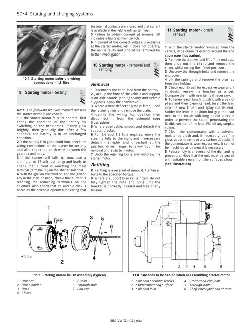
1 Brushes<br />
2 Brush holder<br />
3 Bush<br />
4 Shims<br />
11.1 Starting motor brush assembly (typical)<br />
5 Circlip<br />
6 Through-bolt<br />
7 End cap<br />
the internal contacts are closed and that current<br />
is available at the field windings terminal.<br />
5 Failure to obtain current at terminal 50<br />
indicates a faulty ignition switch.<br />
6 If current at the correct voltage is available<br />
at the starter motor, yet it does not operate,<br />
the unit is faulty and should be removed for<br />
further investigation .<br />
10 Starting motor - removal and<br />
refitting 3<br />
Removal<br />
1 Disconnect the earth lead from the battery.<br />
2 Jack up the front of the vehicle and support<br />
it on axle stands (see “Jacking and vehicle<br />
support”). Apply the handbrake.<br />
3 Where a heat deflector plate is fitted, undo<br />
the retaining nuts and remove the plate.<br />
4 Identify the wiring for position then<br />
disconnect it from the solenoid (see<br />
illustration).<br />
5 Where applicable, unbolt and detach the<br />
support bracket.<br />
6 For 1.6 and 1.8 litre engines, move the<br />
steering fully to the right and if necessary<br />
detach the right-hand driveshaft at the<br />
gearbox drive flange to allow room for<br />
removal of the starter motor.<br />
7 Undo the retaining bolts and withdraw the<br />
starter motor.<br />
Refitting<br />
8 Refitting is a reversal of removal. Tighten all<br />
bolts to the specified torque.<br />
9 Where a support bracket is fitted, do not<br />
fully tighten the nuts and bolts until the<br />
bracket is correctly located and free of any<br />
tension.<br />
1081 <strong>VW</strong> <strong>Golf</strong> & <strong>Jetta</strong><br />
11 Starting motor - brush<br />
renewal 3<br />
1 With the starter motor removed from the<br />
vehicle, wipe clean its exterior around the end<br />
cover (see illustration).<br />
2 Remove the screws and lift off the end cap,<br />
then prise out the circlip and remove the<br />
shims whilst noting their fitted positions.<br />
3 Unscrew the through-bolts and remove the<br />
end cover.<br />
4 Lift the springs and remove the brushes<br />
from their holder.<br />
5 Check each brush for excessive wear and if<br />
in doubt, renew the brushes as a set.<br />
Compare them with new items if necessary.<br />
6 To renew each brush, crush it with a pair of<br />
pliers and then clean its lead. Insert the lead<br />
into the new brush and splay out its end.<br />
Solder the lead in position but grip the lead<br />
next to the brush with long-nosed pliers in<br />
order to prevent the solder penetrating the<br />
flexible section of the lead. File off any surplus<br />
solder.<br />
7 Clean the <strong>com</strong>mutator with a solventmoistened<br />
cloth and, if necessary, use fine<br />
glass paper to remove any carbon deposits. If<br />
the <strong>com</strong>mutator is worn excessively, it cannot<br />
be machined and renewal is necessary.<br />
8 Reassembly is a reversal of the dismantling<br />
procedure. Note that the unit must be sealed<br />
with suitable sealant on the surfaces shown<br />
(see illustration).<br />
11.8 Surfaces to be sealed when reassembling starter motor<br />
1 Solenoid securing screws<br />
2 Starter/mounting surface<br />
3 Solenoid joint<br />
4 Starter/end cap joint<br />
5 Through-bolts<br />
6 Shaft cover joint and screws


