VW MKII A2 MK2 Golf Jetta Fox Service Manual - VAGLinks.com
VW MKII A2 MK2 Golf Jetta Fox Service Manual - VAGLinks.com
VW MKII A2 MK2 Golf Jetta Fox Service Manual - VAGLinks.com
You also want an ePaper? Increase the reach of your titles
YUMPU automatically turns print PDFs into web optimized ePapers that Google loves.
5B•2 Ignition system - transistorised type<br />
1 General information and<br />
precautions<br />
General information<br />
TCI-H system<br />
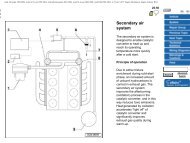
The transistorised (TIC-H) ignition system<br />
functions in a similar manner to that described<br />
in Part A of this Chapter for the contact<br />
breaker system, with the following exceptions.<br />
An electronic sender unit replaces the contact<br />
points and condenser in the distributor and a<br />
remotely-mounted electronic switch unit<br />
controls the coil primary circuit (see<br />
illustrations).<br />
Ignition timing is advanced and retarded<br />
automatically, to ensure that the spark occurs<br />
at just the right instant for the particular load<br />
at the prevailing engine speed.<br />
Ignition advance is controlled both<br />
mechanically and by a vacuum-operated<br />
system. The mechanical governor mechanism<br />
<strong>com</strong>prises two weights, which move out from<br />
the distributor shaft as the engine speed rises<br />
due to centrifugal force. As they move<br />
outwards they rotate the cam relative to the<br />
1 Connector<br />
2 Spark plug<br />
3 HT lead<br />
4 Suppression connector<br />
5 Ignition coil<br />
distributor shaft, and so advance the spark.<br />
The weights are held in position by two light<br />
springs, and it is the tension of the springs<br />
which is largely responsible for correct spark<br />
advancement.<br />
Vacuum control <strong>com</strong>prises a diaphragm,<br />
one side of which is connected via a small<br />
bore pipe to the inlet manifold, and the other<br />
side to the distributor baseplate. Depression<br />
in the inlet manifold, which varies with engine<br />
speed and throttle opening, causes the<br />
diaphragm to move, so moving the baseplate,<br />
and advancing or retarding the spark. A fine<br />
degree of control is achieved by a spring in<br />
the vacuum assembly.<br />
Digifant system<br />
Fitted to the 1.8 litre (code PB and PF)<br />
engine, the Digifant ignition system uses the<br />
TCI-H system described above but in<br />
addition, incorporates a knock sensor which<br />
senses the onset of pre-ignition and retards<br />
ignition timing accordingly. Normal ignition<br />
timing is automatically adjusted by the<br />
Digifant control unit which also controls the<br />
fuel injection system. Because of this, there<br />
are no centrifugal advance weights in the<br />
distributor (see illustration).<br />
1.1a Transistorised ignition system <strong>com</strong>ponents – 1.05 and 1.3 litre engines<br />
6 Terminal (–)<br />
7 Terminal 15 (+)<br />
8 Terminal 4<br />
9 Connectors<br />
10 TCI-H switch unit<br />
11 Connector<br />
12 Heat sink<br />
13 O-ring<br />
14 Distributor<br />
15 Hall sender<br />
1081 <strong>VW</strong> <strong>Golf</strong> & <strong>Jetta</strong><br />
16 Screw<br />
17 Vacuum unit<br />
18 Bearing plate<br />
19 Dust cover<br />
20 Rotor arm<br />
Work procedures are basically as given for<br />
the TIC-H system , except for those described<br />
in the relevant Sections.<br />
Precautions<br />
In addition to the precautions listed in Part<br />
A of this Chapter, note the following:<br />
a) When turning the engine at starter speed<br />
without starting, the HT lead must be<br />
pulled from the centre of the distributor<br />
cap and kept earthed to a suitable part of<br />
the engine or bodywork<br />
b) If the system develops a fault and it is<br />
necessary to tow the vehicle with the<br />
ignition on, the wiring must be<br />
disconnected from the TCI-H switch unit<br />
c) Do not under any circumstances connect<br />
a condenser to the coil terminals<br />
2 Spark plugs - renewal<br />
Refer to Chapter 1, Section 15<br />
21 Carbon brush with<br />
spring<br />
22 Distributor cap<br />
23 Screening ring<br />
24 Earth lead<br />
2


