VW MKII A2 MK2 Golf Jetta Fox Service Manual - VAGLinks.com
VW MKII A2 MK2 Golf Jetta Fox Service Manual - VAGLinks.com
VW MKII A2 MK2 Golf Jetta Fox Service Manual - VAGLinks.com
Create successful ePaper yourself
Turn your PDF publications into a flip-book with our unique Google optimized e-Paper software.
4F•4 Fuel and exhaust systems - Digifant fuel injection<br />
9 Airflow meter - testing<br />
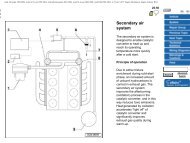
8.1 Fuel injectors and pressure regulator <strong>com</strong>ponents<br />
A Crankcase, ventilation<br />
hose<br />
B Vacuum hose<br />
1 Fuel pressure regulator<br />
2 Bracket<br />
3 Bolt<br />
4 Fuel return hose (blue)<br />
2<br />
1 Disconnect the wiring plug from the airflow<br />
meter (see illustration).<br />
2 Connect an ohmmeter between terminals 1<br />
and 4 and check that the resistance of the<br />
inlet air temperature sender is as shown (see<br />
illustration) according to the ambient air<br />
temperature.<br />
3 Connect the ohmmeter between terminals 3<br />
and 4 and check that the resistance of the<br />
potentiometer is between 0.5 and 1.0 K ohms.<br />
4 Connect the ohmmeter between terminals 2<br />
5 Fuel supply hose (black)<br />
6 Bolt<br />
7 Bracket<br />
8 Crankcase ventilation<br />
pressure regulator valve<br />
9 Connector<br />
10 Temperature sender<br />
11 O-ring<br />
12 Fuel distributor<br />
13 Wiring conduit<br />
14 Clip<br />
15 Plug<br />
16 Injector<br />
17 Insert<br />
and 3 and check that the resistance fluctuates<br />
as the airflow meter plate is moved.<br />
10 Control unit - testing<br />
5<br />
The control unit is located on the left-hand<br />
side of the bulkhead. The ignition must always<br />
be switched off before disconnecting the<br />
plug.<br />
It is not possible to test the control unit<br />
without using the <strong>VW</strong> test appliances. If a fault<br />
is suspected, the unit should be taken to a <strong>VW</strong><br />
dealer.<br />
1081 <strong>VW</strong> <strong>Golf</strong> & <strong>Jetta</strong><br />
11 Overrun cut-off and full<br />
throttle enrichment - testing 2<br />
1 Run the engine until the oil temperature is<br />
at least 80°C (normal operating temperature)<br />
then let the engine idle.<br />
2 <strong>Manual</strong>ly close the full throttle valve switch<br />
2 and hold it closed.<br />
3 Open the throttle until the engine speed is<br />
approximately 2000 rpm. Check that the<br />
engine speed surges, indicating that the<br />
overrun cut-off is functioning.<br />
4 If the engine does not surge, disconnect the<br />
wiring from the temperature sender and<br />
connect a bridging wire between the two<br />
contacts on the plug.<br />
5 Repeat the procedure in paragraphs 2 and<br />
3. If the engine now surges, the temperature<br />
sender is proved faulty. However, if it still<br />
refuses to surge, check the associated wiring<br />
and throttle valve switch 2.<br />
6 If no fault is found, renew the control unit.<br />
12 Fuel pumps - testing<br />
Pre mid 1989<br />
2<br />
1 The main fuel pump is located in the<br />
accumulator housing beneath the rear of the<br />
vehicle. An additional lift pump is located in<br />
the fuel tank, together with the fuel gauge<br />
sender (see illustration).<br />
2 With the engine stopped, have an assistant<br />
switch on the ignition. It should be possible to<br />
hear both pumps running for a short period. If<br />
not, check fuse 5 for continuity and also<br />
check all wiring connections.<br />
3 With the ignition on, disconnect each wire<br />
connector from the pumps and check that<br />
there is a 12 volt supply by using a voltmeter.<br />
4 Should there be no voltage at the pumps<br />
with the ignition switched on, the fuel pump<br />
relay (No 2 on fusebox) may be faulty. This is<br />
best checked by substituting a new relay.<br />
From mid 1989<br />
5 From mid 1989, certain models fitted with<br />
the Digifant system are fitted with a single fuel<br />
pump in the fuel tank rather than the previous<br />
arrangement described above. The pump can<br />
be tested in the same manner as that<br />
described for the previously fitted “in-tank”<br />
dual pump.<br />
6 The fuel pump can be removed in a similar<br />
manner to that described for the fuel gauge<br />
sender unit in Part A of this Chapter, Section<br />
8.


