VW MKII A2 MK2 Golf Jetta Fox Service Manual - VAGLinks.com
VW MKII A2 MK2 Golf Jetta Fox Service Manual - VAGLinks.com
VW MKII A2 MK2 Golf Jetta Fox Service Manual - VAGLinks.com
Create successful ePaper yourself
Turn your PDF publications into a flip-book with our unique Google optimized e-Paper software.
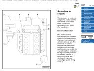
A Front crankcase ventilation<br />
valve<br />
B Vacuum hose connection<br />
from fuel pressure<br />
regulator<br />
C Vacuum hose from air<br />
cleaner temperature<br />
regulator<br />
6.2 Throttle stop adjustment<br />
1 Carrier lever 2 Stop lever<br />
Arrow indicates adjustment screw<br />
5.1 Throttle valve housing <strong>com</strong>ponents<br />
1 Air inlet hose<br />
2 Bolt<br />
3 Idle speed adjustment<br />
4 Throttle valve switch 1<br />
5 Throttle valve switch 2<br />
6 Throttle valve housing<br />
7 Gasket<br />
8 Bracket<br />
9 Bolt<br />
10 Inlet manifold<br />
Fuel and exhaust systems - Digifant fuel injection 4F•3<br />
11 Vacuum hose to brake<br />
servo unit<br />
12 Idle speed stabilisation<br />
control valve<br />
13 Support<br />
14 Gasket<br />
15 Support<br />
16 Bolt<br />
17 Bolt<br />
18 Bracket<br />
1081 <strong>VW</strong> <strong>Golf</strong> & <strong>Jetta</strong><br />
5 Fully open the throttle and align a datum<br />
with 0° on the card. Close the throttle by<br />
approximately 20°, then slowly open it until<br />
switch 2 points close. This should occur at<br />
10° ± 2° before full throttle. If necessary,<br />
adjust the position of switch 2. Note that the<br />
throttle valve lever roller must contact the<br />
sloping part of switch 2.<br />
6 Throttle stop - adjustment<br />
2<br />
1 Throttle stop adjustment is initially set at<br />
the factory and should not be tampered with.<br />
However, if it is accidentally disturbed,<br />
proceed as follows.<br />
2 Back off the adjustment screw until a gap<br />
exists between the carrier lever and stop lever<br />
(see illustration).<br />
3 Turn the adjustment screw until the two<br />
levers just make contact, then continue to turn<br />
it a further half-turn. Tighten the locknut.<br />
4 After making an adjustment, readjust the<br />
throttle valve switches, and the idle speed and<br />
mixture.<br />
7 Fuel pressure regulator -<br />
testing 5<br />
A pressure gauge and adapter is required for<br />
this test. As these will not normally be available<br />
to the home mechanic, it is re<strong>com</strong>mended that<br />
a <strong>VW</strong> dealer carry out the test.<br />
8 Fuel injectors - testing<br />
3<br />
1 Refer to Part B of this Chapter, Section 13,<br />
paragraphs 1 to 3, but in addition, carry out<br />
the following electrical tests (see illustration).<br />
2 Disconnect the wiring plug from the conduit<br />
next to the injectors and connect an<br />
ohmmeter across the terminals on the<br />
conduit. The resistance of all four injectors<br />
should be 3.7 to 5.0 ohms. If any number of<br />
injectors are open-circuited, then the<br />
resistance will be as follows:<br />
One injector open-circuited - 5.0 to 6.7 ohms<br />
Two injectors open-circuited - 7.5 to 10.0<br />
ohms<br />
Three injectors open-circuited - 15.0 to 20.0<br />
ohms<br />
3 If necessary, prise off the conduit and<br />
check that each individual injector has a<br />
resistance of 15.0 to 20.0 ohms.<br />
4 Checking the injector spray patterns cannot<br />
be performed as described in Part B of this<br />
Chapter, due to the position of the fuel<br />
distributor. However, the injectors may be<br />
removed together with the fuel distributor and<br />
wiring conduit, and the engine turned on the<br />
starter for a few seconds. Use a suitable<br />
container to catch the fuel.<br />
4F


