VW MKII A2 MK2 Golf Jetta Fox Service Manual - VAGLinks.com
VW MKII A2 MK2 Golf Jetta Fox Service Manual - VAGLinks.com VW MKII A2 MK2 Golf Jetta Fox Service Manual - VAGLinks.com
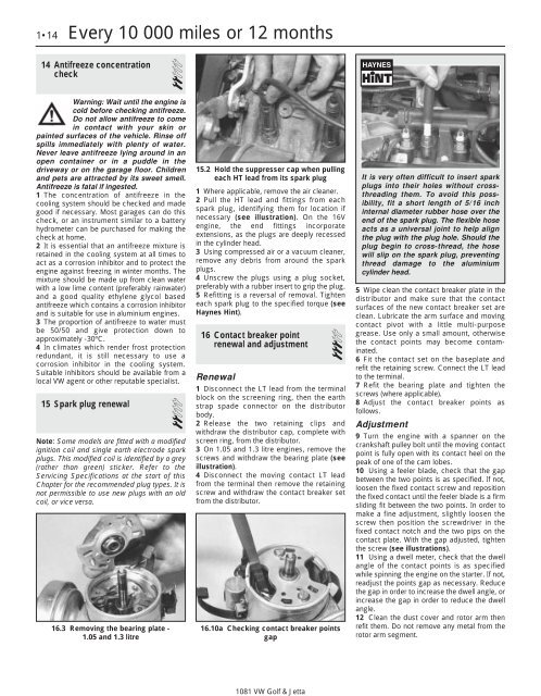
1•14 Every 10 000 miles or 12 months 14 Antifreeze concentration check 2 Warning: Wait until the engine is cold before checking antifreeze. Do not allow antifreeze to come in contact with your skin or painted surfaces of the vehicle. Rinse off spills immediately with plenty of water. Never leave antifreeze lying around in an open container or in a puddle in the driveway or on the garage floor. Children and pets are attracted by its sweet smell. Antifreeze is fatal if ingested. 1 The concentration of antifreeze in the cooling system should be checked and made good if necessary. Most garages can do this check, or an instrument similar to a battery hydrometer can be purchased for making the check at home. 2 It is essential that an antifreeze mixture is retained in the cooling system at all times to act as a corrosion inhibitor and to protect the engine against freezing in winter months. The mixture should be made up from clean water with a low lime content (preferably rainwater) and a good quality ethylene glycol based antifreeze which contains a corrosion inhibitor and is suitable for use in aluminium engines. 3 The proportion of antifreeze to water must be 50/50 and give protection down to approximately -30ºC. 4 In climates which render frost protection redundant, it is still necessary to use a corrosion inhibitor in the cooling system. Suitable inhibitors should be available from a local VW agent or other reputable specialist. 15 Spark plug renewal 2 Note: Some models are fitted with a modified ignition coil and single earth electrode spark plugs. This modified coil is identified by a grey (rather than green) sticker. Refer to the Servicing Specifications at the start of this Chapter for the recommended plug types. It is not permissible to use new plugs with an old coil, or vice versa. 16.3 Removing the bearing plate - 1.05 and 1.3 litre 15.2 Hold the suppresser cap when pulling each HT lead from its spark plug 1 Where applicable, remove the air cleaner. 2 Pull the HT lead and fittings from each spark plug, identifying them for location if necessary (see illustration). On the 16V engine, the end fittings incorporate extensions, as the plugs are deeply recessed in the cylinder head. 3 Using compressed air or a vacuum cleaner, remove any debris from around the spark plugs. 4 Unscrew the plugs using a plug socket, preferably with a rubber insert to grip the plug. 5 Refitting is a reversal of removal. Tighten each spark plug to the specified torque (see Haynes Hint). 16 Contact breaker point renewal and adjustment 3 Renewal 1 Disconnect the LT lead from the terminal block on the screening ring, then the earth strap spade connector on the distributor body. 2 Release the two retaining clips and withdraw the distributor cap, complete with screen ring, from the distributor. 3 On 1.05 and 1.3 litre engines, remove the screws and withdraw the bearing plate (see illustration). 4 Disconnect the moving contact LT lead from the terminal then remove the retaining screw and withdraw the contact breaker set from the distributor. 16.10a Checking contact breaker points gap 1081 VW Golf & Jetta It is very often difficult to insert spark plugs into their holes without crossthreading them. To avoid this possibility, fit a short length of 5/16 inch internal diameter rubber hose over the end of the spark plug. The flexible hose acts as a universal joint to help align the plug with the plug hole. Should the plug begin to cross-thread, the hose will slip on the spark plug, preventing thread damage to the aluminium cylinder head. 5 Wipe clean the contact breaker plate in the distributor and make sure that the contact surfaces of the new contact breaker set are clean. Lubricate the arm surface and moving contact pivot with a little multi-purpose grease. Use only a small amount, otherwise the contact points may become contaminated. 6 Fit the contact set on the baseplate and refit the retaining screw. Connect the LT lead to the terminal. 7 Refit the bearing plate and tighten the screws (where applicable). 8 Adjust the contact breaker points as follows. Adjustment 9 Turn the engine with a spanner on the crankshaft pulley bolt until the moving contact point is fully open with its contact heel on the peak of one of the cam lobes. 10 Using a feeler blade, check that the gap between the two points is as specified. If not, loosen the fixed contact screw and reposition the fixed contact until the feeler blade is a firm sliding fit between the two points. In order to make a fine adjustment, slightly loosen the screw then position the screwdriver in the fixed contact notch and the two pips on the contact plate. With the gap adjusted, tighten the screw (see illustrations). 11 Using a dwell meter, check that the dwell angle of the contact points is as specified while spinning the engine on the starter. If not, readjust the points gap as necessary. Reduce the gap in order to increase the dwell angle, or increase the gap in order to reduce the dwell angle. 12 Clean the dust cover and rotor arm then refit them. Do not remove any metal from the rotor arm segment.
13 Wipe clean the distributor cap and make sure that the carbon brush moves freely against the tension of the spring. Clean the metal segments in the distributor cap but do not scrape away any metal, otherwise the HT spark at the spark plugs will be reduced. Also clean the HT leads and coil tower. 14 Refit the distributor cap and interference screen. 15 Start the engine and check that the dwell angle is as specified, both at idling and higher engine speeds. A decrease in dwell angle at high engine speeds indicates a weak spring on the moving contact points. 16 After making any adjustment to the contact breaker points, check and adjust the ignition timing. 17 Ignition timing check Contact breaker system 3 Note: Accurate ignition timing is only possible using a stroboscopic timing light, although on some models a DC sender unit is located on the top of the gearbox casing and may be Every 10 000 miles or 12 months 1•15 16.10b Adjusting contact breaker points gap 16.10c Two pips and notch (arrowed) for inserting screwdriver when adjusting contact breaker points gap 17.3a Crankshaft pulley mark (A) timing mark (B) and TDC mark (C) (timing cover removed) - 1.3 litre used with a special VW tester to give an instant read-out. However, this tester will not normally be available to the home mechanic. For initial setting-up purposes, the test bulb method can be used but this must always be followed by the stroboscopic timing light method Test bulb method 1 Remove No. 1 spark plug (crankshaft pulley end) and place a thumb over the aperture. 2 Turn the engine in the normal running direction (clockwise viewed from the crankshaft pulley end) until pressure is felt in No. 1 cylinder, indicating that the piston is commencing its compression stroke. Use a spanner on the crankshaft pulley bolt, or engage top gear and pull the vehicle forwards. 3 Continue turning the engine until the line on the crankshaft pulley is aligned with the pointer on the timing cover. If there are no marks on the timing cover, unscrew and remove the DC sensor or blanking plug from the top of the gearbox and align the timing mark (see Specifications) with the timing pointer (see illustrations). 4 Remove the distributor cap and check that the rotor arm is pointing toward the No. 1 HT lead location in the cap. 17.3b TDC timing marks - 1.6 and 1.8 litre A Flywheel/driveplate B Crankshaft pulley 1081 VW Golf & Jetta 5 Connect a 12 volt test bulb between the coil LT negative terminal and a suitable earthing point on the engine. 6 Loosen the distributor clamp retaining bolt. 7 Switch on the ignition. If the bulb is already lit, turn the distributor body slightly clockwise until the bulb goes out. 8 Turn the distributor body anti-clockwise until the bulb just lights up, indicating that the points have just opened. Tighten the clamp retaining bolt. 9 Switch off the ignition and remove the test bulb. 10 Refit the distributor cap and No. 1 spark plug and HT lead. Once the engine has been started, check the timing stroboscopically. Stroboscopic timing light method 11 Run the engine until its normal operating temperature is reached. 12 On 1.05, 1.3 and 1.8 litre fuel injection engines, disconnect and plug the distributor vacuum hose. 13 If there are no timing marks on the timing cover and crankshaft pulley, unscrew and remove the TDC sensor or blanking plug from the top of the gearbox. 14 Connect the timing light in accordance with the manufacturer’s instructions. 17.3c Rotor arm aligned with TDC mark on distributor body – 1.6 and 1.8 litre 1
- Page 1 and 2: Chapter 1 Routine maintenance and s
- Page 3 and 4: CO content (%) 1.05 litre carburett
- Page 5 and 6: The maintenance intervals in this M
- Page 7 and 8: Maintenance - component location 1
- Page 9 and 10: Maintenance - component location 1
- Page 11 and 12: 6 Fluid leakage and engine electric
- Page 13: 9 The engine will turn over more ea
- Page 17 and 18: 18.13 Using a chain wrench to unscr
- Page 19 and 20: 25.3a Bend each brake hose to check
- Page 21 and 22: 32.4b . . . loosen front mounting n
- Page 23 and 24: Chapter 2 Part A: Engine repair pro
- Page 25 and 26: 1.3 litre: Inlet opens . . . . . .
- Page 27 and 28: difficulty is experienced, it may b
- Page 29 and 30: 9 Cylinder head - removal 3 1 If th
- Page 31 and 32: 11 Cylinder head - dismantling and
- Page 33 and 34: 14.13a Withdrawing crankshaft rear
- Page 35 and 36: 21 Crankshaft and bearings - examin
- Page 37 and 38: 29.2 Fitting centre main bearing sh
- Page 39 and 40: 35.9 Camshaft sprocket (later type)
- Page 41 and 42: Chapter 2 Part B: Engine repair pro
- Page 43 and 44: 4.5 Two lengths of metal used to lo
- Page 45 and 46: 9 Oil pump - refitting 3 Refitting
- Page 47 and 48: guide the cylinder head into positi
- Page 49 and 50: Chapter 2 Part C: Engine repair pro
- Page 51 and 52: Stem diameter: Inlet . . . . . . .
- Page 53 and 54: 1 General information The 1.6 and 1
- Page 55 and 56: 26 The engine/gearbox unit is now r
- Page 57 and 58: 9.6 Intermediate sprocket timing ma
- Page 59 and 60: and tappet is required. Label the c
- Page 61 and 62: 13.1 Sump, oil pump and oil filter
- Page 63 and 64: 17 Oil filter - renewal Refer to Ch
1•14 Every 10 000 miles or 12 months<br />
14 Antifreeze concentration<br />
check 2<br />
Warning: Wait until the engine is<br />
cold before checking antifreeze.<br />
Do not allow antifreeze to <strong>com</strong>e<br />
in contact with your skin or<br />
painted surfaces of the vehicle. Rinse off<br />
spills immediately with plenty of water.<br />
Never leave antifreeze lying around in an<br />
open container or in a puddle in the<br />
driveway or on the garage floor. Children<br />
and pets are attracted by its sweet smell.<br />
Antifreeze is fatal if ingested.<br />
1 The concentration of antifreeze in the<br />
cooling system should be checked and made<br />
good if necessary. Most garages can do this<br />
check, or an instrument similar to a battery<br />
hydrometer can be purchased for making the<br />
check at home.<br />
2 It is essential that an antifreeze mixture is<br />
retained in the cooling system at all times to<br />
act as a corrosion inhibitor and to protect the<br />
engine against freezing in winter months. The<br />
mixture should be made up from clean water<br />
with a low lime content (preferably rainwater)<br />
and a good quality ethylene glycol based<br />
antifreeze which contains a corrosion inhibitor<br />
and is suitable for use in aluminium engines.<br />
3 The proportion of antifreeze to water must<br />
be 50/50 and give protection down to<br />
approximately -30ºC.<br />
4 In climates which render frost protection<br />
redundant, it is still necessary to use a<br />
corrosion inhibitor in the cooling system.<br />
Suitable inhibitors should be available from a<br />
local <strong>VW</strong> agent or other reputable specialist.<br />
15 Spark plug renewal<br />
2<br />
Note: Some models are fitted with a modified<br />
ignition coil and single earth electrode spark<br />
plugs. This modified coil is identified by a grey<br />
(rather than green) sticker. Refer to the<br />
Servicing Specifications at the start of this<br />
Chapter for the re<strong>com</strong>mended plug types. It is<br />
not permissible to use new plugs with an old<br />
coil, or vice versa.<br />
16.3 Removing the bearing plate -<br />
1.05 and 1.3 litre<br />
15.2 Hold the suppresser cap when pulling<br />
each HT lead from its spark plug<br />
1 Where applicable, remove the air cleaner.<br />
2 Pull the HT lead and fittings from each<br />
spark plug, identifying them for location if<br />
necessary (see illustration). On the 16V<br />
engine, the end fittings incorporate<br />
extensions, as the plugs are deeply recessed<br />
in the cylinder head.<br />
3 Using <strong>com</strong>pressed air or a vacuum cleaner,<br />
remove any debris from around the spark<br />
plugs.<br />
4 Unscrew the plugs using a plug socket,<br />
preferably with a rubber insert to grip the plug.<br />
5 Refitting is a reversal of removal. Tighten<br />
each spark plug to the specified torque (see<br />
Haynes Hint).<br />
16 Contact breaker point<br />
renewal and adjustment 3<br />
Renewal<br />
1 Disconnect the LT lead from the terminal<br />
block on the screening ring, then the earth<br />
strap spade connector on the distributor<br />
body.<br />
2 Release the two retaining clips and<br />
withdraw the distributor cap, <strong>com</strong>plete with<br />
screen ring, from the distributor.<br />
3 On 1.05 and 1.3 litre engines, remove the<br />
screws and withdraw the bearing plate (see<br />
illustration).<br />
4 Disconnect the moving contact LT lead<br />
from the terminal then remove the retaining<br />
screw and withdraw the contact breaker set<br />
from the distributor.<br />
16.10a Checking contact breaker points<br />
gap<br />
1081 <strong>VW</strong> <strong>Golf</strong> & <strong>Jetta</strong><br />
It is very often difficult to insert spark<br />
plugs into their holes without crossthreading<br />
them. To avoid this possibility,<br />
fit a short length of 5/16 inch<br />
internal diameter rubber hose over the<br />
end of the spark plug. The flexible hose<br />
acts as a universal joint to help align<br />
the plug with the plug hole. Should the<br />
plug begin to cross-thread, the hose<br />
will slip on the spark plug, preventing<br />
thread damage to the aluminium<br />
cylinder head.<br />
5 Wipe clean the contact breaker plate in the<br />
distributor and make sure that the contact<br />
surfaces of the new contact breaker set are<br />
clean. Lubricate the arm surface and moving<br />
contact pivot with a little multi-purpose<br />
grease. Use only a small amount, otherwise<br />
the contact points may be<strong>com</strong>e contaminated.<br />
6 Fit the contact set on the baseplate and<br />
refit the retaining screw. Connect the LT lead<br />
to the terminal.<br />
7 Refit the bearing plate and tighten the<br />
screws (where applicable).<br />
8 Adjust the contact breaker points as<br />
follows.<br />
Adjustment<br />
9 Turn the engine with a spanner on the<br />
crankshaft pulley bolt until the moving contact<br />
point is fully open with its contact heel on the<br />
peak of one of the cam lobes.<br />
10 Using a feeler blade, check that the gap<br />
between the two points is as specified. If not,<br />
loosen the fixed contact screw and reposition<br />
the fixed contact until the feeler blade is a firm<br />
sliding fit between the two points. In order to<br />
make a fine adjustment, slightly loosen the<br />
screw then position the screwdriver in the<br />
fixed contact notch and the two pips on the<br />
contact plate. With the gap adjusted, tighten<br />
the screw (see illustrations).<br />
11 Using a dwell meter, check that the dwell<br />
angle of the contact points is as specified<br />
while spinning the engine on the starter. If not,<br />
readjust the points gap as necessary. Reduce<br />
the gap in order to increase the dwell angle, or<br />
increase the gap in order to reduce the dwell<br />
angle.<br />
12 Clean the dust cover and rotor arm then<br />
refit them. Do not remove any metal from the<br />
rotor arm segment.


