VW MKII A2 MK2 Golf Jetta Fox Service Manual - VAGLinks.com
VW MKII A2 MK2 Golf Jetta Fox Service Manual - VAGLinks.com
VW MKII A2 MK2 Golf Jetta Fox Service Manual - VAGLinks.com
Create successful ePaper yourself
Turn your PDF publications into a flip-book with our unique Google optimized e-Paper software.
4D•4 Fuel and exhaust systems - Mono Jetronic fuel injection<br />
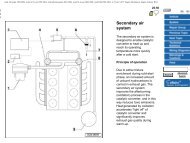
7.5 Injector unit and upper body <strong>com</strong>ponents<br />
1 Screw<br />
2 Injector holder<br />
3 Protector cap<br />
4 O-ring<br />
5 Injector<br />
6 Stud<br />
7 Injector upper body<br />
2 With the engine running at idle speed, look<br />
into the top of the injector unit and check the<br />
fuel spray pattern which should be visible on<br />
the throttle valve.<br />
3 Increase the engine speed to 3000 rpm<br />
then snap shut the throttle and check that the<br />
fuel spray from the injector is momentarily<br />
interrupted. Turn the ignition off and then<br />
check that no more than two drops of fuel per<br />
minute leak from the injector. This indicates<br />
that the overrun cut-off is functioning in a<br />
satisfactory manner.<br />
Removal<br />
4 Remove the inlet duct and manifold.<br />
5 Undo the retaining screw and lift clear the<br />
injector holder and O-ring seal from the top of<br />
the injector. Note its orientation, then grip and<br />
pull the injector from its location in the<br />
housing. Remove the O-ring seals (see<br />
illustration).<br />
8 Gasket<br />
9 Screw<br />
10 Pressure regulator<br />
11 Fuel pipe adapter<br />
12 Seal ring<br />
13 Connector<br />
Refitting<br />
6 Refit in the reverse order of removal. The<br />
O-ring seals must be renewed and lightly<br />
lubricated prior to fitting.<br />
8 Injector unit housing -<br />
removal and refitting 2<br />
Removal<br />
1 Remove the air inlet duct and manifold.<br />
2 Detach the fuel feed and return lines from<br />
their connections on the side of the injector<br />
unit. Allow for fuel spillage as they are<br />
detached and plug the hoses to prevent<br />
further leakage and the ingress of dirt.<br />
3 Disconnect the wiring plugs from their<br />
connections on the injector unit (see<br />
illustration).<br />
1081 <strong>VW</strong> <strong>Golf</strong> & <strong>Jetta</strong><br />
8.3 Injector unit lower body and associated <strong>com</strong>ponents<br />
1 Throttle valve stop screw<br />
2 O-ring<br />
3 Plug<br />
4 Screw<br />
5 Retainer<br />
6 Connector<br />
7 Connector<br />
8 Throttle valve potentiometer<br />
9 Injector lower body<br />
10 Water separator<br />
11 Screw<br />
12 Throttle valve positioner<br />
13 Throttle damper adjuster<br />
screw<br />
14 Throttle damper<br />
15 Bracket<br />
16 Protector grommet (for idle<br />
switch)<br />
17 Idle switch<br />
18 Screw<br />
4 Disconnect the accelerator cable from the<br />
throttle lever at the injector unit.<br />
5 Undo the retaining screws and withdraw<br />
the injector unit housing from the inlet<br />
manifold. Remove the gasket and if damaged<br />
or in doubtful condition, renew it when<br />
refitting the injector unit.<br />
Refitting<br />
6 Refit in the reverse order of removal. Ensure<br />
that the mating faces of the housing and fuel<br />
lines are clean before reconnecting.<br />
9 Throttle damper - adjustment<br />
2<br />
When the throttle valve is in the closed<br />
position, the throttle damper plunger should<br />
be pressed into the damper a minimum


