VW MKII A2 MK2 Golf Jetta Fox Service Manual - VAGLinks.com
VW MKII A2 MK2 Golf Jetta Fox Service Manual - VAGLinks.com
VW MKII A2 MK2 Golf Jetta Fox Service Manual - VAGLinks.com
You also want an ePaper? Increase the reach of your titles
YUMPU automatically turns print PDFs into web optimized ePapers that Google loves.
4D•2 Fuel and exhaust systems - Mono Jetronic fuel injection<br />
1 General information and<br />
precautions<br />
General information<br />
The Mono-Jetronic central fuel injection<br />
system is fitted to the 1.8 litre (code RP)<br />
engine. It is a simplified method of fuel<br />
injection (see illustrations).<br />
Fuel is injected into the inlet manifold by a<br />
single solenoid valve (fuel injector) mounted<br />
centrally in the top of the injector unit housing.<br />
The length of time for which the injector<br />
remains open determines the quantity of fuel<br />
reaching the cylinders for <strong>com</strong>bustion. The<br />
electrical signals which determine the fuel<br />
injector opening duration are calculated by<br />
the Electronic Control Unit (ECU) from<br />
information supplied by its network of<br />
sensors. Fuel pressure is regulated<br />
mechanically.<br />
The signals fed to the ECU include the<br />
following:<br />
a) The engine coolant temperature<br />
b) The engine speed and crankshaft position<br />
- from the distributor<br />
c) The position of the throttle valve plate -<br />
from the throttle position sensor<br />
d) The oxygen content in the exhaust gases<br />
- via a sensor (Lambda probe) in the<br />
exhaust manifold<br />
Using the information gathered from the<br />
various sensors, the ECU sends out signals to<br />
control the system actuators as required.<br />
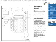
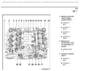
1.0a Mono-Jetronic system <strong>com</strong>ponent location<br />
1 Electronic Control unit (ECU)<br />
2 Connector (throttle valve positioner and<br />
idle switch)<br />
3 Throttle damper<br />
4 Connector (injector and air intake<br />
temperature sender)<br />
5 Throttle valve positioner and idle switch<br />
6 Intake air pre-heater temperature regulator<br />
7 Injector and air temperature sender<br />
8 Fuel pressure regulator<br />
9 Inlet manifold pre-heater<br />
10 Injection timing vacuum control valve<br />
11 Injector<br />
12 Throttle valve potentiometer<br />
13 Water separator (throttle valve<br />
potentiometer)<br />
14 Self diagnosis fault warning lamp<br />
15 Lambda probe connector<br />
16 Activated charcoal filter solenoid valve<br />
17 Activated charcoal filter solenoid valve<br />
18 Injector series resistor<br />
19 Thermoswitch for manifold pre-heater<br />
20 Coolant temperature sender<br />
21 Self diagnosis plug<br />
1081 <strong>VW</strong> <strong>Golf</strong> & <strong>Jetta</strong><br />
The ECU also has a diagnostic function<br />
which can be used in conjunction with special<br />
<strong>VW</strong> test equipment for fault diagnosis. With<br />
the exception of basic checks to ensure that<br />
all relevant wiring and hoses are in good<br />
condition and securely connected, fault<br />
diagnosis should be entrusted to a <strong>VW</strong> dealer.<br />
Basic testing can be carried out on the<br />
system <strong>com</strong>ponents covered in the following<br />
text. More detailed testing can be carried out<br />
by using specialised equipment but this must<br />
be entrusted to a <strong>VW</strong> dealer.<br />
Precautions<br />
Refer to Sections 1 and 2 in Part B of this<br />
Chapter.<br />
2 Air cleaner element - renewal<br />
Refer to Chapter 1, Section 32<br />
1<br />
3 Air inlet duct and manifold -<br />
removal and refitting 2<br />
1 Undo the retaining clips and release the<br />
duct from the manifold and air cleaner.<br />
2 To remove the manifold from the top of the<br />
injector unit housing, detach the hoses from<br />
the temperature sensor unit on the manifold<br />
whilst noting their fitted positions.<br />
3 Undo the retaining bolt and lift the manifold,<br />
together with its gasket, from the top face of<br />
the injector unit.<br />
4 Refit in the reverse order of removal.<br />
4 Air inlet pre-heater - testing<br />
2<br />
1 With the engine cold, detach and remove<br />
the upper section of the air cleaner followed<br />
by the filter element.<br />
2 Check the air flap valve in the base of the<br />
lower section of the air cleaner for freedom of<br />
movement. Ensure that when closed, it shuts<br />
off the warm air passage.<br />
3 Whilst running the engine at idle speed,<br />
check that the flap closes off the cold air<br />
passage.<br />
4 To check that the temperature regulator is<br />
operating correctly, disconnect the two hoses<br />
from it (see illustration), connect them<br />
together and then note if the warm air<br />
passage remains closed off. If this is the case,<br />
the vacuum unit is defective. Where the flap<br />
valve closes off the cold air passage, the<br />
temperature regulator is at fault and in need of<br />
replacement.<br />
5 The position of the flap valve when the<br />
engine is running is dependent on the<br />
temperature of the regulator. When the<br />
temperature is below 35°C, the temperature<br />
regulator should be open and the cold air


