VW MKII A2 MK2 Golf Jetta Fox Service Manual - VAGLinks.com
VW MKII A2 MK2 Golf Jetta Fox Service Manual - VAGLinks.com
VW MKII A2 MK2 Golf Jetta Fox Service Manual - VAGLinks.com
You also want an ePaper? Increase the reach of your titles
YUMPU automatically turns print PDFs into web optimized ePapers that Google loves.
4C•2 Fuel and exhaust systems - K-Jetronic fuel injection - 16 valve engines<br />
1 General information<br />
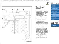
The <strong>com</strong>ponents of the K-Jetronic fuel<br />
injection system fitted to the 1.8 litre 16V<br />
engine are as shown (see illustrations). All<br />
procedures are the same as described in Part<br />
B of this Chapter except for those given in the<br />
following Sections.<br />
1 Union bolt<br />
2 O-rings<br />
3 Bolt<br />
4 Union bolt<br />
5 Union bolt<br />
6 Fuel metering distributor<br />
7 Adjusting shim<br />
8 O-rings<br />
9 Pressure regulator and<br />
relief valve<br />
10 Fuel supply and return<br />
11 Spring<br />
12 Control plunger<br />
13 Plug<br />
14 Mixture (CO content)<br />
adjustment screw<br />
15 Airflow<br />
16 Union nut<br />
17 Injector<br />
18 O-rings<br />
19 Injector insert<br />
20 Gasket<br />
21 Cold start valve<br />
22 Temperature sender<br />
23 Thermotime switch<br />
24 Connector (blue)<br />
25 Connector (brown)<br />
26 Vacuum connection<br />
27 Warm-up valve<br />
28 Connector (grey)<br />
2 Idle speed - adjustment<br />
4<br />
1 Run the engine to normal operating<br />
temperature, then check that all electrical<br />
<strong>com</strong>ponents are switched off. Note that the<br />
electric cooling fan must not be running<br />
during the adjustment procedure.<br />
2 Disconnect the crankcase ventilation hose<br />
(see illustration).<br />
3 Connect a tachometer and an exhaust gas<br />
analyser to the engine.<br />
4 If the injector pipes have been removed and<br />
1081 <strong>VW</strong> <strong>Golf</strong> & <strong>Jetta</strong><br />
refitted just prior to adjustment, run the engine<br />
to 3000 rpm several times then allow it to idle<br />
for at least two minutes.<br />
5 Check that when the ignition is switched<br />
on, the idling stabilisation control valve is<br />
heard to buzz. If not, check the system with<br />
reference to Section 3.<br />
6 Disconnect the wiring plug for the idle<br />
stabilisation system. This is located near the<br />
ignition coil (see illustration).<br />
7 Allow the engine to idle, then check that the<br />
idle speed is 1000 ± 50 rpm. If necessary,<br />
remove the cap and turn the idle speed<br />
adjustment screw as required (see<br />
illustration).<br />
1.0a K-Jetronic fuel injection system <strong>com</strong>ponents – 16v engine


