

VW MKII A2 MK2 Golf Jetta Fox Service Manual - VAGLinks.com
VW MKII A2 MK2 Golf Jetta Fox Service Manual - VAGLinks.com
VW MKII A2 MK2 Golf Jetta Fox Service Manual - VAGLinks.com

Create successful ePaper yourself
Turn your PDF publications into a flip-book with our unique Google optimized e-Paper software.
4 Switch off all electrical consumers, then<br />
pinch the air hose again and adjust idle speed<br />
to that specified. When the correct idle speed<br />
is reached, unclamp the hose. The idle speed<br />
should then increase up to about 1050 rpm at<br />
which point the valve will close and the speed<br />
drop to the specified idle speed setting.<br />
Valve 2 - checking<br />
5 Run the engine at normal idle speed with<br />
the air conditioner switched off. Pinch the air<br />
hose and check that the engine speed<br />
remains the same.<br />
6 Now switch the air conditioning on and<br />
repeat the test. When the hose is pinched, the<br />
engine speed should drop.<br />
7 If the air hose and/or valves Nos. 1 or 2 are<br />
disconnected or removed for any reason, it is<br />
important when refitting to note that the<br />
three-way hose connector large hole must go<br />
to valve No. 2.<br />
7 Idle mixture - adjustment<br />
4<br />
Note: Accurate idle mixture adjustment can<br />
only be made using an exhaust gas analyser<br />
1 The idle CO adjustment screw alters the<br />
height of the fuel metering distributor plunger<br />
relative to the air control plate of the air flow<br />
meter.<br />
2 The screw is accessible by removing the<br />
locking plug from between the air duct scoop<br />
and the fuel metering distributor on the airflow<br />
meter casing (see illustration).<br />
3 Although a special tool is re<strong>com</strong>mended for<br />
this adjustment, it can be made using a long,<br />
thin screwdriver.<br />
4 Ensure that the engine is running under the<br />
same conditions as those necessary for<br />
adjusting the idling speed and that the idling<br />
speed is correct.<br />
5 Connect an exhaust gas analyser to the<br />
tailpipe, as directed by the equipment<br />
manufacturer, and read the CO level.<br />
Fuel and exhaust systems - K-Jetronic fuel injection - 8 valve engines 4B•5<br />
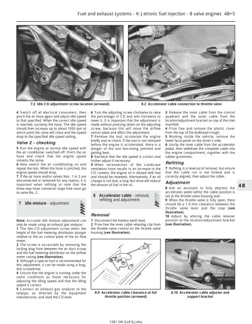
7.2 Idle CO adjustment screw location (arrowed) 8.2 Accelerator cable connection to throttle valve<br />
6 Turn the adjusting screw clockwise to raise<br />
the percentage of CO and anti-clockwise to<br />
lower it. It is important that the adjustment is<br />
made without pressing down on the adjusting<br />
screw, because this will move the airflow<br />
sensor plate and affect the adjustment.<br />
7 Remove the tool, accelerate the engine<br />
briefly and re-check. If the tool is not removed<br />
before the engine is accelerated, there is a<br />
danger of the tool be<strong>com</strong>ing jammed and<br />
getting bent.<br />
8 Recheck that the idle speed is correct and<br />
further adjust if necessary.<br />
9 When reconnection of the crankcase<br />
ventilation hose results in an increase in the<br />
CO content, the engine oil is diluted with fuel<br />
and should be renewed. Alternatively, if an oil<br />
change is not due, a long fast drive will reduce<br />
the amount of fuel in the oil.<br />
8 Accelerator cable - removal,<br />
refitting and adjustment 2<br />
Removal<br />
1 Disconnect the battery earth lead.<br />
2 Prise free the inner cable retaining clip from<br />
the throttle valve control on the throttle valve<br />
housing (see illustration).<br />
8.9 Accelerator cable clearance at full<br />
throttle position (arrowed)<br />
1081 <strong>VW</strong> <strong>Golf</strong> & <strong>Jetta</strong><br />
3 Release the inner cable from the control<br />
quadrant and the outer cable from the<br />
location/adjustment bracket on top of the inlet<br />
manifold.<br />
4 Prise free and remove the plastic cover<br />
from the top of the bulkhead trough.<br />
5 Working inside the vehicle, remove the<br />
lower facia panel on the driver’s side.<br />
6 Unclip the inner cable from the accelerator<br />
pedal, then withdraw the <strong>com</strong>plete cable into<br />
the engine <strong>com</strong>partment, together with the<br />
rubber grommets.<br />
Refitting<br />
7 Refitting is a reversal of removal, but ensure<br />
that the cable run is not kinked and is<br />
correctly aligned, then adjust the cable.<br />
Adjustment<br />
8 Ask an assistant to fully depress the<br />
accelerator pedal whilst the cable position is<br />
set at the throttle valve housing end.<br />
9 When the throttle valve is fully open, there<br />
should be a 1.0 mm clearance between the<br />
throttle valve lever and the stop (see<br />
illustration).<br />
10 Adjust by altering the cable retainer<br />
position at the location/adjustment bracket<br />
(see illustration).<br />
8.10 Accelerator cable adjuster and<br />
support bracket<br />
4B


