VW MKII A2 MK2 Golf Jetta Fox Service Manual - VAGLinks.com
VW MKII A2 MK2 Golf Jetta Fox Service Manual - VAGLinks.com
VW MKII A2 MK2 Golf Jetta Fox Service Manual - VAGLinks.com
Create successful ePaper yourself
Turn your PDF publications into a flip-book with our unique Google optimized e-Paper software.
4B•2 Fuel and exhaust systems - K-Jetronic fuel injection - 8 valve engines<br />
Torque wrench settings Nm lbf ft<br />
Injector insert . . . . . . . . . . . . . . . . . . . . . . . . . . . . . . . . . . . . . . . . . . . . . 20 15<br />
Injector line to injector . . . . . . . . . . . . . . . . . . . . . . . . . . . . . . . . . . . . . . 25 18<br />
Injector line to fuel metering distributor . . . . . . . . . . . . . . . . . . . . . . . . . 10 7<br />
Thermo-time switch . . . . . . . . . . . . . . . . . . . . . . . . . . . . . . . . . . . . . . . . 30 22<br />
System pressure relief valve . . . . . . . . . . . . . . . . . . . . . . . . . . . . . . . . . . 20 15<br />
Cold start valve . . . . . . . . . . . . . . . . . . . . . . . . . . . . . . . . . . . . . . . . . . . . 10 7<br />
Throttle valve housing to manifold . . . . . . . . . . . . . . . . . . . . . . . . . . . . . 20 15<br />
Inlet manifold . . . . . . . . . . . . . . . . . . . . . . . . . . . . . . . . . . . . . . . . . . . . . 25 18<br />
Fuel filter clamp . . . . . . . . . . . . . . . . . . . . . . . . . . . . . . . . . . . . . . . . . . . 10 7<br />
Union bolt at filter (from fuel accumulator) . . . . . . . . . . . . . . . . . . . . . . . 25 18<br />
Union nut at accumulator (to filter) . . . . . . . . . . . . . . . . . . . . . . . . . . . . . 20 15<br />
Union bolt at filter (to metering distributor) . . . . . . . . . . . . . . . . . . . . . . . 20 15<br />
Fuel pump reservoir mounting . . . . . . . . . . . . . . . . . . . . . . . . . . . . . . . . 10 7<br />
Fuel pump non-return valve . . . . . . . . . . . . . . . . . . . . . . . . . . . . . . . . . . 20 15<br />
Fuel pump damper unit . . . . . . . . . . . . . . . . . . . . . . . . . . . . . . . . . . . . . 20 15<br />
Inlet manifold nuts/bolts . . . . . . . . . . . . . . . . . . . . . . . . . . . . . . . . . . . . . 20 15<br />
Exhaust manifold . . . . . . . . . . . . . . . . . . . . . . . . . . . . . . . . . . . . . . . . . . 25 18<br />
Exhaust heat shield . . . . . . . . . . . . . . . . . . . . . . . . . . . . . . . . . . . . . . . . 10 7<br />
Exhaust pipe clamp bolts . . . . . . . . . . . . . . . . . . . . . . . . . . . . . . . . . . . . 40 30<br />
1 General information and<br />
precautions<br />
General information<br />
The principle of the K-Jetronic continuous<br />
injection system is very simple and there are<br />
no specialised electronic <strong>com</strong>ponents. There<br />
is an electrically driven fuel pump and<br />
electrical sensors and switches but these are<br />
no different from those in general use on<br />
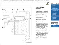
vehicles (see illustration).<br />
The following paragraphs describe the<br />
system and its various elements. Later<br />
Sections describe tests which can be carried<br />
out to ascertain whether a particular unit is<br />
functioning correctly. Repairs are not<br />
generally possible.<br />
The system measures the amount of air<br />
entering the engine and determines the<br />
amount of fuel which needs to be mixed with<br />
the air to give the correct <strong>com</strong>bustion mixture<br />
for the particular conditions of engine<br />
operation. Fuel is sprayed continuously by an<br />
injection nozzle to the inlet port of each<br />
cylinder. This fuel/air mixture is drawn into the<br />
cylinder when the inlet valves open.<br />
1.0 K-Jetronic fuel injection system air intake <strong>com</strong>ponents - 8v engine<br />
1081 <strong>VW</strong> <strong>Golf</strong> & <strong>Jetta</strong><br />
Airflow meter<br />
The airflow meter measures the volume of<br />
air entering the engine and <strong>com</strong>prises an air<br />
funnel with a sensor plate mounted on a lever<br />
which is supported at its fulcrum. The weight<br />
of the airflow sensor plate and its lever are<br />
balanced by a counterweight and the upward<br />
force on the sensor plate is opposed by a<br />
plunger. The plunger, which moves up and<br />
down as a result of the variations in air flow, is<br />
surrounded by a sleeve having vertical slots in<br />
it. The vertical movement of the plunger<br />
uncovers a greater or lesser length of the slots,<br />
which meters fuel to the injection valves.


