

VW MKII A2 MK2 Golf Jetta Fox Service Manual - VAGLinks.com
VW MKII A2 MK2 Golf Jetta Fox Service Manual - VAGLinks.com
VW MKII A2 MK2 Golf Jetta Fox Service Manual - VAGLinks.com

You also want an ePaper? Increase the reach of your titles
YUMPU automatically turns print PDFs into web optimized ePapers that Google loves.
4A•20 Fuel and exhaust systems - carburettor models<br />
17.30 Stage II vacuum unit control<br />
1 Thermo-pneumatic valve<br />
2 Restrictor<br />
3 Straight connection hose<br />
28 Stop the engine by disconnecting the coil<br />
terminal 15, and check that the diaphragm rod<br />
remains in the overrun/cut-off position for a<br />
minimum of five seconds.<br />
29 Reconnect the coil wiring, control valve<br />
plug and hose where applicable. Refit the air<br />
cleaner.<br />
Stage ll vacuum control unit<br />
30 This device is fitted to 1.6 litre manual<br />
gearbox models and 1.8 automatic gearbox<br />
models from August 1984 on. Its function is to<br />
delay the Stage ll opening slightly whilst the<br />
coolant temperature is below 18°C. It<br />
achieves this by venting the vacuum hose via<br />
the thermo-pneumatic valve and the resistor<br />
(see illustration).<br />
31 Check that the straight hose at connection<br />
3 on the thermo-pneumatic valve is not<br />
blocked and check the valve itself by blowing<br />
through it. It should be open at 18°C and close<br />
when the temperature rises above 28°C.<br />
Idle/overrun control valve<br />
32 Entrust this operation to your <strong>VW</strong> dealer as<br />
specialised testing equipment is necessary.<br />
Temperature time valve<br />
33 Entrust this operation to your <strong>VW</strong> dealer<br />
as specialised testing equipment is<br />
necessary.<br />
Slow running and fast idle<br />
34 To check and adjust the slow running<br />
setting, proceed as described in Section 15,<br />
paragraphs 7 to 13 inclusive whilst noting the<br />
following differences:<br />
a) Before making any adjustments, ensure<br />
that the three/four point unit pushrod is in<br />
the idling position with the cold idling<br />
adjusting screw touching the pushrod<br />
b) If adjustment is necessary, turn the idling<br />
speed control valve and CO adjustment<br />
screw (see illustrations), as necessary.<br />
c) Access to the CO adjustment screw is<br />
gained by prising out the tamperproof<br />
plug. If the CO content is difficult to<br />
adjust, remove the adjustment screw and<br />
clean its point, then refit and adjust it<br />
35 On automatic transmission models, the<br />
increased idling speed can be checked and<br />
adjusted as follows. In addition to those<br />
preliminary requirements necessary when<br />
checking the idle speed slow running setting,<br />
the hand brake must be fully applied and<br />
chocks placed against the wheels.<br />
36 When the engine is started, turn on the<br />
fresh air blower (fully), switch on the headlights<br />
(high beam) and the heated rear window. Get<br />
an assistant to sit in the vehicle and depress<br />
the foot brake then select D. Check that the<br />
four point unit diaphragm rod is in the<br />
increased idling position, the fast idle adjuster<br />
screw rests against the diaphragm rod and the<br />
engine increased idle speed is not under that<br />
specified. Adjust if necessary by altering the<br />
regulator valve setting (see illustration).<br />
37 On models fitted with air conditioning, the<br />
procedure for checking the increased idling<br />
speed is similar to that for automatic<br />
17.36 Engine speed regulator valve (1) 17.39a Disconnect and plug vacuum hose<br />
(1) to check/adjust engine fast idle speed<br />
adjustment<br />
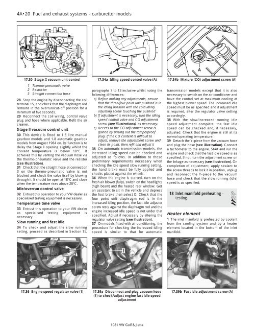
17.34a Idling speed control valve (A) 17.34b Mixture (CO) adjustment screw (A)<br />
1081 <strong>VW</strong> <strong>Golf</strong> & <strong>Jetta</strong><br />
transmission models except that it is also<br />
necessary to switch on the air conditioner and<br />
have the control set at maximum cooling at<br />
the highest blower speed. The increased idle<br />
speed must be as specified and if adjustment<br />
is required, alter the regulator valve setting<br />
accordingly.<br />
38 With the slow/increased running idle<br />
speed adjustment <strong>com</strong>plete, the fast idle<br />
speed can be checked and, if necessary,<br />
adjusted. Check that the engine is still at its<br />
normal operating temperature.<br />
39 Detach the Y-piece from the vacuum hose<br />
and plug the hose (see illustration). Connect<br />
a tachometer to the engine. Start and run the<br />
engine and check that the fast idle speed is as<br />
specified. If not, turn the adjustment screw on<br />
the linkage as necessary (see illustration). On<br />
<strong>com</strong>pletion of adjustment, apply sealant to<br />
the screw threads to lock it in position, unplug<br />
and reconnect the Y-piece to the vacuum<br />
hose and check that the slow running (idle)<br />
speed is as specified.<br />
18 Inlet manifold preheating -<br />
testing 2<br />
Heater element<br />
1 The inlet manifold is preheated by coolant<br />
from the cooling system and by a heater<br />
element located in the bottom of the inlet<br />
manifold.<br />
17.39b Fast idle adjustment screw (A)


