Introduction to Parachute Subsonic Aerodynamics
Introduction to Parachute Subsonic Aerodynamics
Introduction to Parachute Subsonic Aerodynamics

Create successful ePaper yourself
Turn your PDF publications into a flip-book with our unique Google optimized e-Paper software.
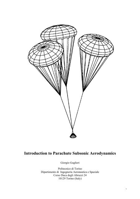
<strong>Introduction</strong> <strong>to</strong> <strong>Parachute</strong> <strong>Subsonic</strong> <strong>Aerodynamics</strong><br />
Giorgio Guglieri<br />
Politecnico di Torino<br />
Dipartimen<strong>to</strong> di Ingegneria Aeronautica e Spaziale<br />
Corso Duca degli Abruzzi 24<br />
10129 Torino (Italy)<br />
1
<strong>Parachute</strong>s<br />
The material presented here will cover a short his<strong>to</strong>rical discussion, a look at structure, general<br />
configuration and then aerodynamics in both steady state and transient phases. In the aerodynamics<br />
sub-section some existing empirical models for drag, deceleration and filling time will be presented.<br />
<strong>Introduction</strong> and His<strong>to</strong>rical Perspective<br />
<strong>Parachute</strong>s have been in use for a long time, as far back as two thousand years the Chinese used<br />
them. Three centuries after Leonardo da Vinci made drawings of parachutes in the fifteenth century<br />
they were being used in flight. However a major miles<strong>to</strong>ne in parachute development had <strong>to</strong> wait<br />
until the 1930’s.<br />
It was at the Flugtechnisches Institut der Technischen Hochschule Stuttgart (FIST) beginning in<br />
1933 that more serious and thoughtful development of parachutes was begun. The purpose of the<br />
research and development that they were undertaking was <strong>to</strong> find the most suitable method of<br />
decelerating an aircraft in-flight and then landing safely. In order <strong>to</strong> achieve this the parachute<br />
needed <strong>to</strong> have reliable and controllable inflation, high drag, low opening shock, stability, simple<br />
design and construction and simple maintenance. To achieve the above characteristics it was found<br />
that increasing the porosity of the canopy gave an increase in stability whilst giving a decrease in<br />
drag. The result of this work was the FIST Ribbon <strong>Parachute</strong>, 1938.<br />
<strong>Parachute</strong> technology has in the past taken the approach of development by evolution, also know as<br />
trial and error. Which is <strong>to</strong> say that flight-testing was the primary method of iterating the design<br />
process and gathering experience. This design philosophy worked very well and many good<br />
parachutes have been born out of this process. However as the flight envelopes and cost of payloads<br />
began <strong>to</strong> grow so did the costs associated with flight-testing. For this reason the time taken for<br />
development had <strong>to</strong> be reduced significantly.<br />
Reduction of development time, as caused by the disappearing availability of flight test time, meant<br />
that a more analytical approach had <strong>to</strong> be adopted. In the case of parachute design this is not such a<br />
simple thing because the fluid dynamics involve separated, unsteady flows that are coupled with the<br />
structural dynamics of a flexible structure. The construction of approximate models was the only<br />
option available. Indeed this still remains the only option available, however over many years of<br />
dedicated research the knowledge of the phenomena involved in parachute aerodynamics has been<br />
steadily improving.<br />
2
Description of <strong>Parachute</strong>s<br />
General <strong>Parachute</strong> Description and Components<br />
The purpose of the parachute is <strong>to</strong> decelerate and provide stability <strong>to</strong> a payload in flight. The<br />
aerodynamic and stability characteristics of the parachute system are governed by the geometry of<br />
the parachute, as such careful consideration is paid <strong>to</strong> this in the design process. S<strong>to</strong>rage should be<br />
efficient in terms of volume and packed weight, as well as allowing a rapid and reliable<br />
deployment. The effects of deployment and opening force are critical in the safe operation of the<br />
parachute and the integrity of the payload. The opening characteristics also feature heavily in the<br />
selection of geometry and other parameters in the design process.<br />
<strong>Parachute</strong>s are in general symmetric about the system axis. This axis passes through the center of<br />
the canopy and the confluence point of the suspension lines. The canopy is the cloth surface that<br />
inflates in order <strong>to</strong> provide the desired lift, drag and stability. The suspension lines transmit the<br />
retarding force from the canopy <strong>to</strong> the payload, either directly or through risers attached below the<br />
confluence point of the suspension lines <strong>to</strong> the body. The point of convergence of all suspension<br />
lines of a parachute is called the confluence point. The position extending below the major diameter<br />
of the inflated canopy <strong>to</strong> the leading edge of the canopy is the skirt. The crown is the region of the<br />
canopy above the major diameter of the inflated shape. The small circular opening at the center of<br />
the crown is called the vent. The apex is the center of the canopy. A general circular parachute<br />
layout is given below in Figure 1. Square parachutes, like the ones used widely in sporting<br />
applications, will not be investigated since the parachutes used for aerospace applications are not of<br />
this type.<br />
<strong>Parachute</strong>s are formed from an even number of gores. The gore length is measured along the center<br />
of the gore from the vent band <strong>to</strong> the skirt band. The simplest gore shape is triangular with a linear<br />
variation of gore width between the vent band and the skirt band. Some parachutes use shaped gores<br />
<strong>to</strong> optimize aerodynamic characteristics and / or minimize material stresses.<br />
The parachute nominal area S0 is the actual three-dimensional canopy constructed surface area. For<br />
most canopy designs, S0 is computed as the sum of the gore areas inclusive of vent area slots, and<br />
their openings within the gore outline. Areas of surfaces such as ribs, flares, panels, or additional<br />
fullness <strong>to</strong> the cloth are also included. Nominal diameter D0 is the diameter of a circle whose area<br />
is S0 .<br />
A second reference dimension of parachutes is the constructed diameter Dc . The constructed<br />
diameter is the diameter of the parachute when projected on a planar surface. For the flat circular<br />
parachute type these is the actual “as-built” diameter of the canopy. Therefore the nominal diameter<br />
is the hypothetical effective diameter, and the constructed diameter concerns the actual dimension<br />
of the parachute.<br />
Aerodynamic forces change the shape of the canopy from its constructed configuration <strong>to</strong> a concave<br />
scalloped con<strong>to</strong>ur when it fills <strong>to</strong> its inflated shape. To characterize the dimensions of the inflated<br />
decelera<strong>to</strong>r in constant-velocity flight requires projecting the area of the inflated canopy on<strong>to</strong> the<br />
plane of the skirt reinforcement. This measured projected area is noted as SP . Projected diameter<br />
DP is defined as the diameter of a circle with area equal <strong>to</strong> the measured projected area.<br />
Two other parameters of the flat circular parachute is the vent opening diameter DV which is<br />
directly proportional <strong>to</strong> the safe deployment of the parachute and the depth of inflated parachute hP<br />
which characterizes the momentum of the air trapped in<strong>to</strong> the concave shape.<br />
3
Figure 1<br />
There are a number of different kinds of parachutes that have been designed for various<br />
applications. The different applications parachutes are typically used for are pilot, drogue,<br />
deceleration, descent, extraction, supersonic drogue and stabilization. A list of parachute type, drag<br />
coefficient and application is given below in Table 1.<br />
4
Figure 2<br />
<strong>Parachute</strong> Type CD General Application<br />
Flat Circular Ribbon 0.45 – 0.50 Pilot, Drogue, Deceleration, Descent<br />
Conical Ribbon 0.50 – 0.55 Pilot, Drogue, Deceleration, Descent<br />
Lifting Conical Ribbon 0.55 – 0.65 Lifting S<strong>to</strong>res (L/D~0.7)<br />
Hemisflo Ribbon 0.30 – 0.46 Supersonic Drogue<br />
Ringslot 0.56 – 0.65 Extraction, Deceleration, Descent<br />
Ringslot / Solid Canopy 0.85 – 0.95 Deceleration, Descent<br />
Ringsail 0.75 – 0.90 Descent<br />
Disk-Gap-Band 0.52 – 0.58 Supersonic Drogue, Descent<br />
Guide Surface (Ribbed) 0.28 – 0.42 Stabilization, Pilot, Drogue, Descent<br />
Guide Surface (Ribless) 0.30 – 0.34 Pilot, Drogue, Descent<br />
Rotafoil 0.85 – 0.99 Drogue<br />
Vortex Ring 1.50 – 1.80 Descent<br />
Table 1<br />
5
Conical Ribbon <strong>Parachute</strong>s<br />
The Conical Ribbon parachute will be dealt with in more detail, the reason being that it is this type<br />
of parachute being widely used for aerospace applications. The conical ribbon parachute makes use<br />
of a shaped gore <strong>to</strong> produce the conical canopy when inflated. The conical ribbon parachute has an<br />
advantage over the flat circular ribbon parachute because it has ≅10% higher drag without a<br />
decrease in stability. So for this reason the conical ribbon parachute is far more widely used in high<br />
performance applications.<br />
As the demands placed on parachutes have risen the need for higher strength <strong>to</strong> weight ratios has<br />
led <strong>to</strong> number of modifications <strong>to</strong> this kind of parachute. One of these modifications is <strong>to</strong> use a<br />
continuous ribbon. Instead of ribbons being separate entities for each gore that are then sewn<br />
<strong>to</strong>gether at the junction between each gore, there is one ribbon that goes the entire way around the<br />
parachute. This method reduces the number of joints and as such makes the parachute stronger for<br />
an equal mass. Another improvement that has been made is <strong>to</strong> align the verticals perpendicular <strong>to</strong><br />
the continuous ribbon thus changing them from verticals <strong>to</strong> mini-radials. This serves <strong>to</strong> lessen any<br />
stress concentrations that occur from the verticals not being aligned at 90° <strong>to</strong> the ribbons. This is<br />
known as “all radial construction”.<br />
To optimise the usage of material in the parachute, areas of high stress concentration are identified.<br />
The breaking strength of the ribbons in these areas are significantly higher than in others. Typically<br />
the ribbons close <strong>to</strong> the apex and leading edge are of the highest breaking strength, with the<br />
remainder of ribbons of lower strength. Also the width of the ribbons may be different throughout<br />
the parachute, this is <strong>to</strong> tailor the amount of load that will be taken at a particular point or for an<br />
aerodynamic purpose.<br />
Discussion of <strong>Parachute</strong> <strong>Aerodynamics</strong><br />
The dynamics of parachutes are complex and difficult <strong>to</strong> model accurately. During both the<br />
inflation process and the terminal descent stage, the dynamics of a parachute are governed by a<br />
coupling between the structural dynamics of the parachute system and the surrounding fluid flow.<br />
Both these dynamic systems must be addressed as a coupled system in order <strong>to</strong> gain a proper<br />
representation of the dynamic system as a whole.<br />
When the parachute is in a steady state the air flowing around the parachute will separate at some<br />
location on the canopy. The shedding of the vortices from the canopy can affect the canopy stability<br />
and cause a periodic motion of both parachute and payload. The wake from a porous parachute<br />
consists of air that flowed around the canopy and air that flowed through the canopy. Generally the<br />
payload - in the speed range of parachute usage - sheds a very turbulent wake. Part of the flow that<br />
is entering the parachute is therefore of a disturbed nature and should be considered regarding the<br />
aerodynamic performance of the parachute. For many high-performance parachutes, this change in<br />
oncoming airflow can be quite significant during the time required for the parachute <strong>to</strong> inflate. The<br />
implication of a rapid deceleration is that second order effects are likely <strong>to</strong> be present.<br />
To summarize, calculation of parachute deployment, inflation, and deceleration requires a solution<br />
<strong>to</strong> the full Navier-S<strong>to</strong>kes equations for a turbulent, separated airflow around and through blunt<br />
bodies. The parachute is also a flexible body having dynamic behavior coupled with the behavior of<br />
the flow which passes through and around it.<br />
6
From the above description it is obvious a full time dependent solution of this system is far from<br />
being feasible. To make a mathematical model that is feasible simplifications must be made. As<br />
long as the model can be validated satisfac<strong>to</strong>rily by experiment, simplification is not seen <strong>to</strong> be a<br />
problem.<br />
Steady State <strong>Parachute</strong> Drag<br />
The aerodynamic drag produced by the parachute decelerates the payload and accelerates the air in<br />
the vicinity of the parachute. The primary source of parachute drag is the pressure differential<br />
across the canopy. The parachute drag, D, is related <strong>to</strong> parachute drag area, CDSP the air density ρ,<br />
and the velocity V.<br />
1 2<br />
D = ρV<br />
C D S P<br />
Equation 1<br />
2<br />
The drag area CDSP of a parachute depends on its type, inflated shape, size, Reynolds number,<br />
Mach number, Froude number, material elasticity, and porosity. Depending on the relative size and<br />
positions of the parachute and its payload, the payload wake may also affect the parachute drag.<br />
Due <strong>to</strong> the absence theoretical methods drag coefficients are generally determined experimentally,<br />
either from captive tests (wind-tunnels) or from free-flight tests (aircraft drop, balloon drop).<br />
Conical Ribbon <strong>Parachute</strong> Drag Coefficient<br />
In an effort <strong>to</strong> understand the steady state flow characteristics of parachutes it is now useful <strong>to</strong> look<br />
at how the drag coefficient is related <strong>to</strong> various parachute parameters.<br />
<strong>Parachute</strong> Shape<br />
Figure 3<br />
7
Figure 3 shows the change in drag coefficient for changing diameter ratio (inflated diameter divided<br />
by constructed diameter). The trend that can be seen in this graph is as expected. Diameter ratio is a<br />
non-dimensional measure of how elongated the parachute is when inflated. Increasing diameter<br />
ratio is associated with a decrease in elongation. As elongation decreases it would be expected that<br />
the flow would separate at a point closer <strong>to</strong> the leading edge and as such produce a larger area of<br />
high pressure differential across the parachute.<br />
Porosity and Suspension Line Length<br />
Figure 4<br />
Figure 4 shows both the effects of porosity and suspension line length ratio on drag coefficient.<br />
Again both these parameters behave with a trend that is expected. Increasing porosity corresponds<br />
<strong>to</strong> a decrease in drag coefficient. This is due <strong>to</strong> the porosity decreasing the pressure differential<br />
across the parachute. The effect of decreasing the suspension line length causes the line angle <strong>to</strong><br />
increase an as a result the inward radial component of the line load becomes larger. When this<br />
happens the diameter that the parachute can open <strong>to</strong> is restricted thus causing a decrease in drag<br />
coefficient.<br />
8
Figure 5<br />
Figure 5 shows the above described effect of suspension line length more clearly over a larger range<br />
of suspension line length ratio.<br />
Reefing<br />
Figure 6<br />
9
The term reefing is used when the diameter of the parachute is restricted, this has the effect of<br />
limiting the drag area of the parachute. The purpose of reefing is <strong>to</strong> limit the opening-shock load on<br />
the parachute. The reefing line may be severed at a latter point <strong>to</strong> then allow the parachute <strong>to</strong> fully<br />
open and provide greater drag. Reefing may be carried out in more than one stage <strong>to</strong> control the<br />
deceleration more closely. A typical payload deceleration is shown below in Figure 6, note should<br />
be taken of the effect of reefing. Reefing is usually performed by a band passing though the skirt<br />
ribbon. The reefing lines are usually released by a pyrotechnic. Reefing also has positive effects on<br />
stability, below in Table 2 the effect of reefing on drag coefficient and static stability can be seen.<br />
Where Dr is the reefed diameter and Dc is the constructed diameter.<br />
Clustering<br />
Dr/Dc CD (for α=0) (dCm/dα) α=0<br />
1.000 0.533 -0.0012<br />
0.466 0.365 -0.0014<br />
0.366 0.280 -0.0052<br />
0.282 0.205 -0.0109<br />
0.172 0.115 -0.0063<br />
Table 2<br />
There are various advantages and disadvantages associated with clustering. Clustered parachutes<br />
open more quickly than a single parachute of the same size, they allow a degree of redundancy, the<br />
same type of parachute may be used for varying payload weights. Clustering of parachutes does<br />
reduce the drag coefficient of canopies. The amount by which the drag coefficient is affected is<br />
related <strong>to</strong> riser length and the number of canopies. Below (Figure 7) the effect of the number of<br />
canopies, for a given riser length, on cluster efficiency fac<strong>to</strong>r is shown. As the number of canopies<br />
increases the efficiency of the cluster decreases.<br />
Figure 7<br />
10
Transient <strong>Aerodynamics</strong><br />
Transient aerodynamics refers <strong>to</strong> the period when time dependant events are taking place. In short<br />
this refers <strong>to</strong> the period when the parachute is inflating.<br />
Snatch Loads<br />
The snatch load is defined as the force imposed on the suspended load by the decelera<strong>to</strong>r <strong>to</strong><br />
accelerate the mass of the decelera<strong>to</strong>r from its velocity at line extension <strong>to</strong> the velocity of the<br />
payload. It should be noted that snatch loads are imposed before inflation, an example of a<br />
measured snatch load can be seen in Figure 6.<br />
Snatch loads have the potential, when excessively large, <strong>to</strong> damage parachute components and<br />
mechanisms. Damage is usually caused as a result of the inertial loads that are generated by such a<br />
shock. Controlling the snatch load can be achieved in a number of ways. One way is <strong>to</strong> pack the<br />
parachute bag in such a way as <strong>to</strong> deploy the lines before the canopy, this means that the canopy is<br />
not able the increase the differential in velocity between the parachute and payload. A second way<br />
of reducing snatch loads is <strong>to</strong> decrease the mass of the parachute, this serves <strong>to</strong> minimise the<br />
amount of mass that must be accelerated. Also reducing the uninflated area or the area of the drogue<br />
or pilot parachute will reduce the snatch load. However changing these parameters could have<br />
unwanted effects on the inflation and deployment of the parachute and as such should be treated<br />
with care.<br />
Canopy Inflation<br />
Upon being pulled free from the deployment bag the parachute will begin <strong>to</strong> inflate. Air flows in<br />
through the opening at the skirt and becomes trapped inside the canopy. The trapped air will rise in<br />
pressure as more air enters the canopy. When the pressure rises above the air pressure outside the<br />
canopy the canopy will begin <strong>to</strong> expand. The rate and extent of expansion is dependant on a number<br />
of things. Expansion rate is restricted by the aerodynamic forces acting on the outside of canopy.<br />
The aerodynamic forces are determined by the instantaneous shape of the canopy. Also effecting<br />
the rate of expansion is the porosity of the canopy and the size of the vent. It can be intuitively seen<br />
that the porosity and vent size have a strong influence on the internal pressure since they dictate<br />
how much air is allowed <strong>to</strong> pass through the canopy. The extent of inflation is dictated by the<br />
diameter of the skirt band ribbon and or the length of reefing lines.<br />
The amount of porosity should not be so excessive so as <strong>to</strong> not allow full inflation. If this is the case<br />
an oscilla<strong>to</strong>ry motion called “squidding” can occur, where the canopy inflates and deflates in a<br />
periodic motion.<br />
Below in Figure 8 a typical inflation sequence can be seen.<br />
11
1.1 <strong>Parachute</strong> stability<br />
Figure 8<br />
Most of the drag generated by a parachute is created by the pressure differential between the<br />
upstream (concave) and downstream (convex) sides of the canopy. The magnitude of the drag ( and<br />
therefore the performance of the parachute) is largely determined by the magnitude and distribution<br />
of pressure differential across the canopy. The canopy pressure distribution also determines the<br />
stability of the canopy, and it must be known in order <strong>to</strong> predict stresses throughout the canopy<br />
material during the inflation process.<br />
The stability of the parachute may affect the motion of payload and the trajec<strong>to</strong>ry of the<br />
payload/parachute system.<br />
The stability of the parachute depends on its canopy configuration, its location behind its payload,<br />
and the interaction of the payload wake with the parachute. <strong>Parachute</strong> aerodynamics considers two<br />
classes of stability. The parachute is considered <strong>to</strong> be statically stable if it returns <strong>to</strong> its equilibrium<br />
position when it is displaced from its equilibrium position. The parachute is considered <strong>to</strong> be<br />
dynamically stable if its aerodynamic moments and forces damp out unsteady motion. A third type<br />
of parachute “stability” involves the constancy of the canopy’s inflated shape rather than the motion<br />
of the parachute with respect <strong>to</strong> its payload. Although this is not stability in the classical sense, the<br />
stability of the inflated shape of the canopy is important for achieving adequate deceleration.<br />
Static stability<br />
A parachute is statically stable at angles-of-attack where the pitching-moment coefficient<br />
C m decreases with increasing angle-of-attack i.e. Cmα αeq<br />
( ) < 0 .<br />
12
It should be noted that the formal mathematical definition of static stability contradicts the common<br />
vocabulary used by parachute research. The flat circular parachutes (solid canopy) meet the formal<br />
mathematical stability criteria for equilibrium at large angles-of-attack. They exhibit limit cycles or<br />
pendulum motions with an amplitude of 25 degrees from the flow direction. Hence, these<br />
parachutes are sometimes considered <strong>to</strong> be “unstable”. In the case of solid flat circular parachutes,<br />
the airflow separates from the leading edge of the hemisphere in alternating vortices. This<br />
alternating flow separation causes large differences in the skirt’s pressure differential on opposite<br />
sides of the canopy, which in turn produce large destabilizing normal forces and large amplitudes of<br />
oscillation. Now, for parachute of this type with geometric porosity, part of the air flows through<br />
the canopy and pushes vortices in the near wake farther downstream behind the canopy. Since more<br />
air passes through the canopy, less air flows around the canopy skirt; hence, the vortices shed at the<br />
skirt are weaker for porous-canopy parachutes than for solid-canopy parachutes. Separation can<br />
occur at each slot in the canopy, rather than only at the skirt. As a result, the air flow separates more<br />
uniformly around the canopy, thereby minimizing the destabilizing alternate flow separation of the<br />
vortex trail. This is the aerodynamic design principle for the stable ribbon and slotted parachute<br />
canopies.<br />
From past systematic analysis, it can also be observed that the static stability increases with<br />
increasing riser length. An example is when the forebody is small relative <strong>to</strong> the parachute diameter,<br />
the destabilizing effect of the wake on the parachute’s static stability is negligible. Problems can be<br />
avoided when small parachutes are used as drogues or payload stabilizers by placing the parachute<br />
far behind the payload. If this is not possible, the strong body wake interaction with a smalldiameter<br />
parachute (at both subsonic and supersonic deployment conditions) requires very careful<br />
design trade-off on type of parachute, suspension line length, permanent reefing, porosity, and gore<br />
shaping. Using a porous canopy and placing it as far behind the payload as practical (10 body<br />
diameters aft of the base is desirable) are perhaps the most effective design strategies for<br />
minimizing wake effects on static stability.<br />
Dynamic stability<br />
A system is dynamically stable when the parachute’s aerodynamic forces and moments decrease the<br />
amplitude of each succeeding oscillation <strong>to</strong>wards zero or <strong>to</strong> a small steady-state amplitude. In<br />
general, achieving acceptable dynamic stability has not been a major problem in high-performance<br />
parachute design. This conclusion is largely due <strong>to</strong> the fact hat high-performance parachutes usually<br />
have high porosity, which gives them excellent static and dynamic stability.<br />
Inflation instabilities<br />
Inflation instabilities can cause a parachute <strong>to</strong> lose drag and <strong>to</strong> develop motions that may fatigue<br />
canopy materials and result in the failure of the parachute (Figure 9). These instabilities are not<br />
related <strong>to</strong> the slope of the pitching moment curve. They are caused by the periodic coupling<br />
between the canopy shape and the unsteady airflow in and around the canopy. At low speeds,<br />
(subsonic interval of 0.7 Mach) inflation instabilities are often called “squidding” and are usually<br />
observed in parachutes whose porosity is so high that inflation becomes marginal. In order <strong>to</strong><br />
understand those instabilities, it is useful <strong>to</strong> begin from the very first inflation stages of the<br />
parachute.<br />
The inflation stages of a circular parachute are easy <strong>to</strong> visualize. After unfurling out of the bag, the<br />
parachute first adopts a rather elongated shape, not dissimilar <strong>to</strong> that of a vertical tube opened at its<br />
lower end. Because of the system's rapid descent, air rushes in through the tube's opening and<br />
accumulates at the apex of the canopy <strong>to</strong> create a high pressure air “bubble”. Steady inflow<br />
continues <strong>to</strong> build up internal pressure, thus allowing the bubble's volume <strong>to</strong> expand horizontally as<br />
13
well as vertically. However, there is more expansion along the vertical than the horizontal. This<br />
process goes on until the bubble is large enough <strong>to</strong> occupy the entire design volume of the<br />
parachute.<br />
The shape of the expanding air bubble being trapped inside the canopy is dictated by the balance of<br />
aerodynamic forces that act in opposite directions along the boundary defined by the parachute's<br />
fabric. The bubble's expansion rate first depends on the pressure differential between the outside<br />
and inside of the parachute. Like for any blunt objects (generic payload) moving through air, wake<br />
turbulence generated on the downwind side of the parachute causes the external pressure <strong>to</strong> be<br />
lower than the internal pressure near the apex.<br />
The faster the parachute, the larger the pressure differential, the faster the inflow in<strong>to</strong> the parachute<br />
and, consequently, the faster the bubble expansion. On the other hand, rapid expansion generates a<br />
large external pressure which squeezes the bubble on its upwind side, thus slowing down the<br />
expansion. Again, this squeezing effect increases with the parachute's descent speed.<br />
The balance between these fac<strong>to</strong>rs (i.e. rapid inflow, low external pressures near the apex and<br />
squeezing force at the lower end) is achieved by the bubble adopting the “optimal” shape and leads<br />
<strong>to</strong> faster expansion along the vertical than the horizontal. Because the parachute/payload system<br />
decelerates during inflation, this balance of pressure inside and outside the parachute is<br />
continuously readjusted as the inflow becomes slower.<br />
Figure 9<br />
On the other hand we need not <strong>to</strong> decelerate very fast, by means, <strong>to</strong> pay extra attention on the<br />
opening forces (aerodynamic forces) acting on our inflated canopy. The opening forces in some<br />
designs may be so large <strong>to</strong> cause the destruction of the parachute itself and <strong>to</strong>tal damage of its<br />
payload. Typically, if a parachute inflates <strong>to</strong>o quickly, little or no deceleration has occurred: the<br />
parachute and its load still travel at very large speeds by the time the parachute has opened, thus<br />
generating a very large amount of drag and consequently a large force on the parachute structures.<br />
14
Reefing devices are used <strong>to</strong> limit - for a given time - the rate of canopy expansion during the early<br />
phase of inflation. With some circular parachutes for example, a line routed around the skirt limits<br />
the inflow and permits early deceleration, until a pyrotechnic device cuts the latter at a preset time<br />
or altitude.<br />
Canopy porosity also plays an important role in establishing the inflation rate. When the <strong>to</strong>tal<br />
porosity is excessive, the radial forces generated by the pressure inside the canopy may not exceed<br />
the inward component of the load in the suspension lines. This results in an oscilla<strong>to</strong>ry motion of<br />
the canopy, which s<strong>to</strong>ps the inflation process. Permanent reefing of the ribbon canopy can eliminate<br />
the subsonic oscillations.<br />
It can be concluded that permanent reefing, extended skirts, improved porosity, and gore shaping<br />
improve subsonic parachute drag, enhance stability, and reduce the maximum opening-shock loads<br />
of ribbon parachutes.<br />
15
Added Mass Approximation<br />
When a parachute passes through the air it drags some of the surrounding with it, this means that<br />
this air must be accelerated from rest up <strong>to</strong> the speed of the parachute. The parachute will also<br />
accelerate some of the air immediately in front and behind. The energy that is required <strong>to</strong> facilitate<br />
this acceleration is taken from the kinetic energy of the payload parachute system.<br />
These fluid inertia effects are taken in<strong>to</strong> account in the equation of motion by the “Added Mass<br />
Approximation”. The idea is that the mass in this equation has a component added <strong>to</strong> take in<strong>to</strong><br />
account the extra mass m a associated with the accelerated air. This can be seen below in Equation<br />
2, where the change in momentum of the payload/parachute system (mass m b) is equal <strong>to</strong> the sum<br />
of the drag force and gravitational force component.<br />
d<br />
dt MV<br />
1<br />
[ ] = −<br />
2 ρV2 CDSP + mbgsinθ Equation 2<br />
M = m a + m b Equation 3<br />
After combining Equations 2 and 3 and then rearranging the following expression for system<br />
acceleration (or deceleration) can be used.<br />
( mb + ma)<br />
dV 1<br />
= −<br />
dt 2 ρV 2 CDSP − V dma<br />
dt + mbgsinθ Equation 4<br />
However for Equation 4 <strong>to</strong> be useful an expression or knowledge of ma(t) must be known. Shown<br />
below is an expression for added mass, similar <strong>to</strong> that for apparent mass, that has been used widely:<br />
ma = ka 4<br />
3 ρπr3 Equation 5<br />
The value of ka, a constant, can be found in various ways. From a purely analytical approach for<br />
example, potential flow around simple geometric shapes can be used. For example Ibrahim used<br />
potential flow solutions for flow around spherical cups (ka=1.068), whereas Klimas used potential<br />
flow solutions for flow around a vortex sheet (ka=0.994). Klimas also calculated values of ka for<br />
porous hemispherical ribbon parachutes. These calculations are useful <strong>to</strong> us because they offer a<br />
usable method of estimating ka. Figure 10 shows the relationship between ka and porosity λ<br />
(ka=1.068 for zero porosity) for hemispherical ribbon parachutes. Using this figure a value for ka at<br />
any porosity can then be estimated.<br />
16
Figure 10<br />
Equation 4 and 5 can then be combined <strong>to</strong> give the following expression for acceleration.<br />
− dV<br />
dt =<br />
1<br />
2 ρV 2 CDS +8kaπr 2 ⎡⎡<br />
1 dr<br />
⎢⎢<br />
⎣⎣<br />
V dt<br />
mb + ka 4<br />
3 πρr3<br />
− 2<br />
ρV<br />
⎤⎤<br />
2<br />
mbgsinθ<br />
⎥⎥<br />
⎦⎦<br />
Equation 6<br />
The significance of fluid inertial effects has been verified by flight tests over the years, one such<br />
example being in 1944. The US Army Corps tested personnel parachutes at varying altitudes for the<br />
same indicated airspeed. The result of this testing showed that opening times and loads increased<br />
with altitude. The reason for this can be seen when it is considered that at increasing altitude the<br />
true airspeed will increase for constant indicated airspeed, as such the inertial effects of the air are<br />
greater.<br />
After comparison with flight test data the added mass approximation tends <strong>to</strong> over estimate the<br />
deceleration that will occur. From a structural design point of view this means that results obtained<br />
from the added mass approximation can be viewed as conservative. This is of course assuming that<br />
the loads in other phases of parachute operation (for example snatch) are not larger. So while the<br />
concept of added mass is only an approximation, the effects of fluid inertia in transient parachute<br />
aerodynamics are significant enough <strong>to</strong> be included in modeling. At present this method of<br />
accounting for the inertial effects of air is the most practical <strong>to</strong>ol available <strong>to</strong> be used in the transient<br />
phase of parachute operation.<br />
Filling Time<br />
Due <strong>to</strong> the complexity involved with the filling process, filling time is not able <strong>to</strong> be calculated by a<br />
purely analytical method. The alternative once again lies with an empirical approach that is<br />
validated by flight test. Knackle worked on ideas presented by French and O’Hara <strong>to</strong> arrive at the<br />
following empirical relation for filling time.<br />
17
t f = 8D 0<br />
V S 0.9<br />
Where D0 is nominal diameter (ft) and VS is velocity at line stretch (ft/s).<br />
Equation 7<br />
It should be noted here that Equation 7 is dimensionally incorrect. This means that the actual<br />
physics of the system are not properly represented. While Equation 7 has been shown <strong>to</strong> provide<br />
reasonably good answers, care should always be taken in using such an equation so that it is not<br />
being used outside the intended range of conditions.<br />
References<br />
Maydew, R.C., Peterson, C.W., “Design and Testing of High-Performance <strong>Parachute</strong>s”, AGARD-<br />
AG-319, 1991<br />
“Deployable Aerodynamic Deceleration Systems”, NASA-SP-8066, 1971<br />
18
Flat circular ribbon parachute<br />
19
Conical ribbon parachute<br />
20
Slanted ribbon lifting parachute<br />
21
Hemisflo parachute<br />
22
Ringslot parachute<br />
23
Ringsail parachute<br />
24
Disk-gap-band parachute<br />
25
Ribless guide surface parachute<br />
26
Rotafoil parachute<br />
27


![[12.06.12] Coordinamento di Aeroporto 2012](https://img.yumpu.com/16337305/1/190x143/120612-coordinamento-di-aeroporto-2012.jpg?quality=85)

![[11.06.10] Lo strato limite turbolento](https://img.yumpu.com/16319523/1/184x260/110610-lo-strato-limite-turbolento.jpg?quality=85)